Loading ...
Loading ...
Loading ...
7
INPUT SECTION
The RD500/1 employs a differential-balanced
input topology that provides the user with a
high degree of input flexibility, while retaining
superior noise rejection. This type of circuit
also allows the RD500/1 to accept high-voltage
inputs from factory source unit outputs without
excessive distortion or noise problems.
Remote
Level
Control
(RBC-1)
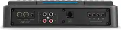
Mono Subwoofer Output
INPUT SECTION
(
L
)
(
R
)
(
L
)
(
R
)
PREOUTS
+12 VDC Ground Remote
You may run a stereo or a mono signal into
the inputs of the amplifier. The amplifier’s input
section automatically sums stereo signals to mono
for the internal amplifier section. The amplifier
will operate with only one input connection but
will require an increase in input sensitivity to
overcome the loss of signal. If a single mono input
signal is used, you may use a “Y-adaptor” to split
the mono signal into both inputs of the amplifier.
If you are feeding only one input and using either
the DC-Offset or Signal Sensing “Turn-On
Mode”, you must use the left-channel input for
the automatic turn-on to operate.
INPUT VOLTAGE RANGE
A wide range of signal input voltages
can be accommodated by the RD500/1’s
input section (200mV – 8V). This wide
range is split up into two sub-ranges,
accessible via the “Input Voltage” switch:
“Low”: for preamp level signals
“High”: for speaker level signals
The “Low” position on the “Input Voltage”
switch selects an input sensitivity range
between 200mV and 2V. This means that the
“Input Sensitivity” rotary control will operate
within that voltage window. If you are using
an aftermarket source unit, with conventional
preamp level outputs, this is the position you
should select.
The “High” position on the “Input Voltage”
switch selects an input sensitivity range between
800mV and 8V for all input channels. This is
useful for certain high-output preamp level
signals as well as speaker-level output from source
units and small amplifiers. To use speaker-level
sources, splice the speaker output wires of the
source unit or small amplifier onto a pair of RCA
cables or plugs or use the JL Audio ECS Speaker
Wire to RCA adaptor (XD-CLRAIC2-SW).
Line output converters are usually not needed
with the RD500/1. If you find that the output
cannot be reduced sufficiently with a direct
speaker level signal applied to the amplifier and
the “Input Voltage” switch in its “High” position,
you may use a line output converter or voltage
divider to reduce the signal level.
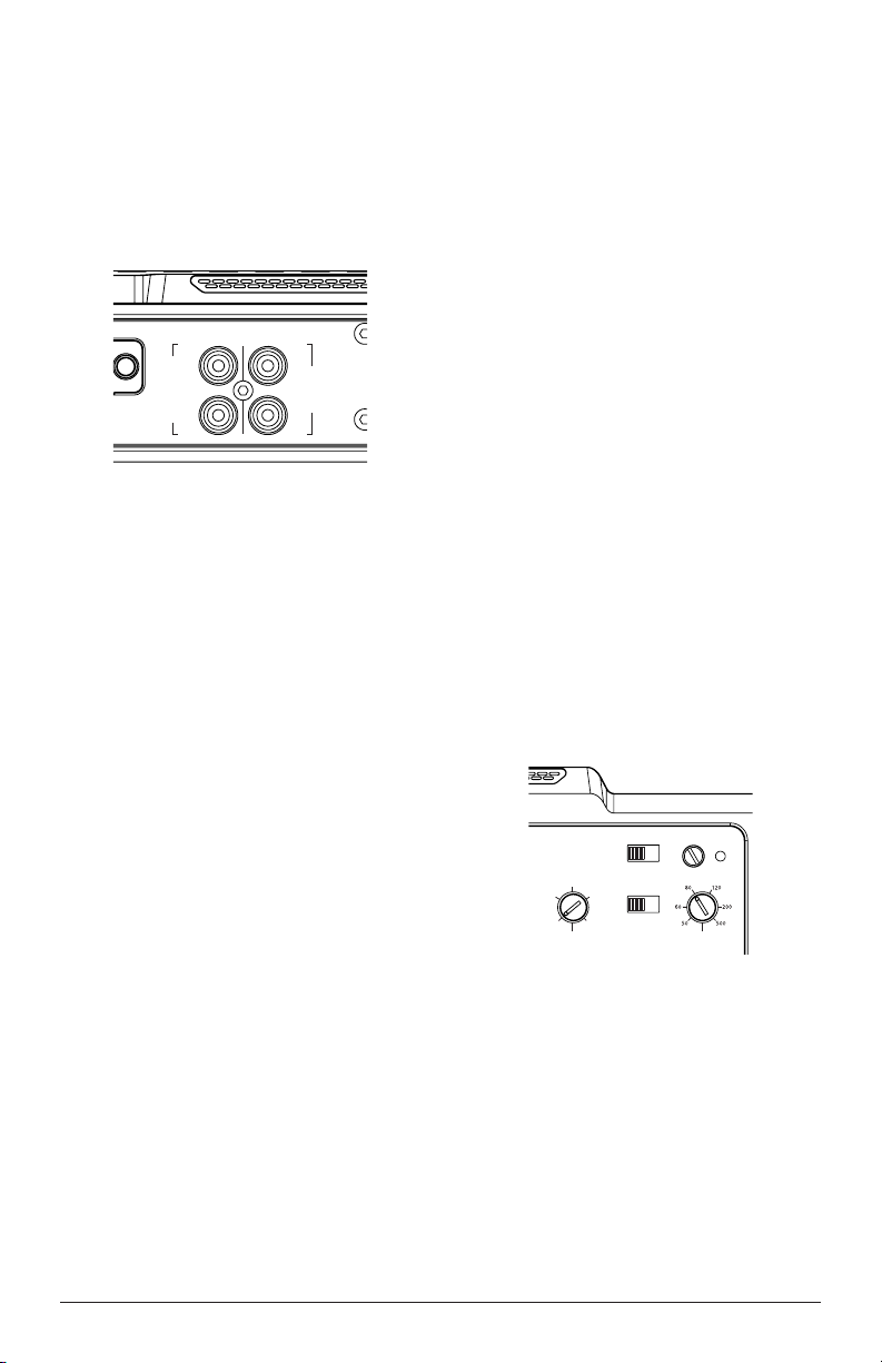
INPUT SENSITIVITY CONTROLS
The control labeled “Input Sensitivity” and
“Clipping” LED are used to match the source
unit’s output voltage to the input stage of the
RD500/1 for maximum clean output. Rotating the
control clockwise will result in higher sensitivity
(louder for a given input voltage). Rotating the
control counter-clockwise will result in lower
sensitivity (quieter for a given input voltage).
+12 VDC Ground
Remote
Input Voltage
Low
|
High
Rem.
|
Oset
|
Signal
Clipping
Turn On Mode
Bass Boost (dB)
LP Filter Freq. (Hz)
Input Sensitivity
Monoblock Subwoofer Amplifier
MONO SUBWOOFER OUPUT
(
L
)
(
R
)
CH. 1
(
L
)
CH. 2
(
R
)
INPUT SECTION
PRE-OUTS
0
+12
+5
+10
+8
To properly set the amplifier for maximum
clean output, please refer to Appendix A (page
12) in this manual. After using this procedure,
you can then adjust the “Input Sensitivity”
levels downward if this is required to achieve the
desired system balance.
Do not increase any “Input Sensitivity”
setting for any channel(s) of any amplifier in the
system beyond the maximum level established
during the procedure outlined in Appendix
A (page 12). Doing so will result in audible
distortion and possible speaker damage.
Loading ...
Loading ...
Loading ...