Loading ...
Loading ...
Loading ...
11
ENGLISH
ELECTRICAL CONNECTION
(Intended only for qualied personnel)
Disconnect the equipment from electrical mains power supply before carry-
ing out any operations on the hood.
Ensure that the wires inside the hood are not disconnected or cut:
in the event of damage, contact your nearest Servicing Department.
Refer to qualied personnel for electrical connections.
Connection must be carried out in compliance with the provisions of law in force.
Before connecting the hood to the electrical mains power supply, check that:
• voltage supply corresponds with what is reported on the data plate located inside the
hood;
• the electrical system is compliant and can withstand the load (see the technical speci-
cations located inside the hood);
• the power supply plug and cable do not come into contact with temperatures exceed-
ing 158°F (70 °C);
• the power supply system is eectively and properly connected to earth in compliance
with regulations in force;
•
the socket used to connect the hood is within reach.
In case of:
• devices tted with cables without a plug: the type of plug to use is a ''standardised'' one.
The wires must be connected as follows: yellow-green for grounding, blue for neutral
and brown for the live. The plug must be connected to an adequate safety socket.
•
xed equipment not provided with a power supply cable and plug, or any other device
that ensures disconnection from the electrical mains, with an opening gap of the con-
tacts that enables total disconnection in overvoltage category III conditions.
Said disconnection devices must be provided in the mains power supply in compliance
with installation regulations.
The cable must not be cut o by the switch.
The Manufacturer declines all responsibility for failure to comply with the safety regulations.
FUMES DISCHARGE
EXTERNAL EXHAUST HOOD SUCTION
In this version the fumes and vapours are discharged outside through
the exhaust pipe.
To this end, the hood outlet tting must be connected via a pipe, to an
external output.
The outlet pipe must have:
• a diameter not less than that of the hood tting.
• a slight slope downwards (drop) in the horizontal sections to prevent condensation from
owing back into the motor.
• the minimum required number of bends.
• the minimum required length to avoid vibrations and reduce the suction performance of
the hood.
You are required to insulate the pipes if it passes through cold environments.
In the presence of motors with 800m
3
/h or higher, a check valve is present to prevent
external air owing back.
ASSEMBLY INSTRUCTIONS
Intended only for qualied personnel
The hood can be installed in various congurations.
The generic assembly steps apply to all installations; for each case, follow
the specic steps provided for the required installation.
OPERATION
WHEN TO TURN ON THE HOOD?
Switch on the hood at least one minute before starting to cook to direct fumes and vapours
towards the suction surface.
After cooking, leave the hood operating until complete extraction of all vapours and odours.
By means of the Timer function, it is possible to set auto switch-o function which will allow
the hood to turn o automatically after 15 minutes of operation.
WHICH SPEED IS TO BE SELECTED?
1st speed: maintains the circulation of clean air with low electricity consumption.
2nd speed: normal conditions of use.
3rd speed: presence of strong odours and vapours.
WHEN SHOULD THE FILTERS BE WASHED OR REPLACED?
The metal lters must be cleaned every 30 hours of operation.
For further details refer to the “MAINTENANCE” section.
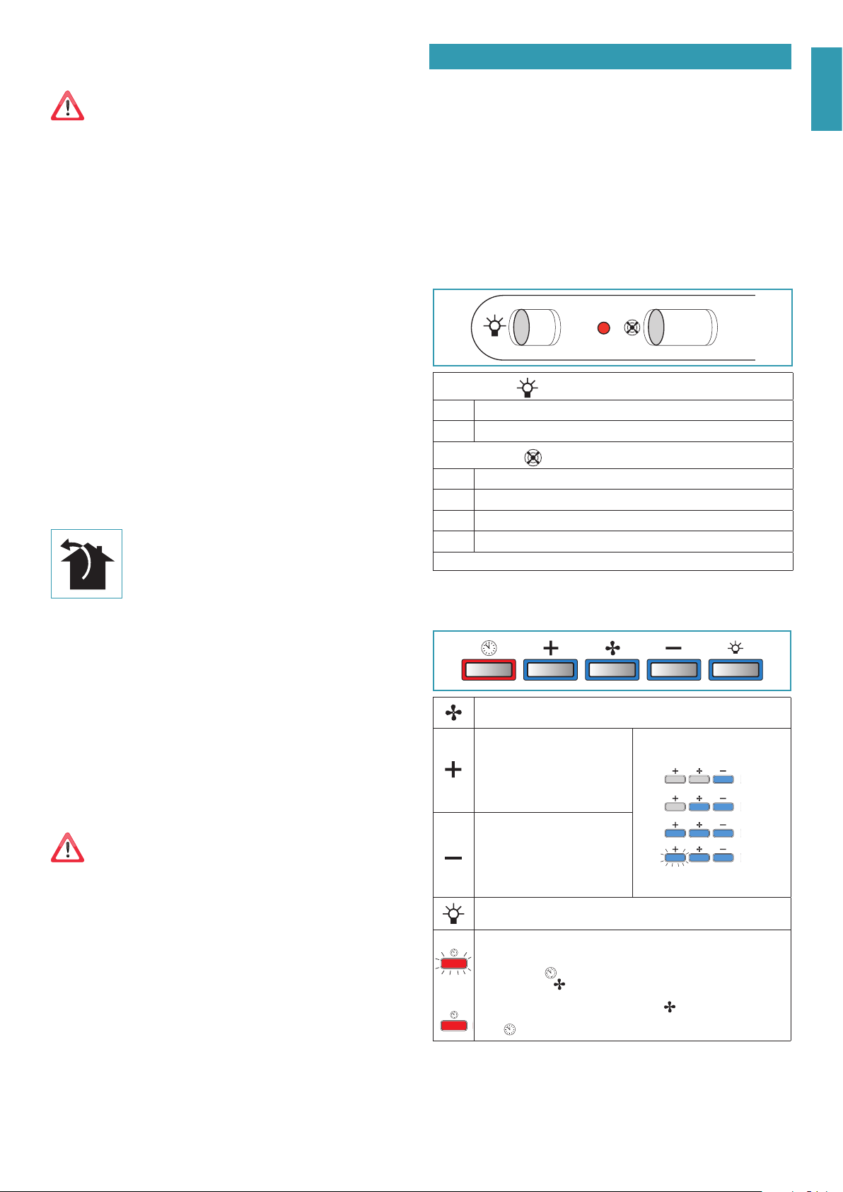
USE OF SLIDER
01 0123
LIGHT SWITCH
0
By placing the slider in position 0, the hood light is o
1
By placing the slider in position 1, the hood light is on
MOTOR SWITCH
0
By placing the slider in position 0, the hood motor is o
1
By placing the slider in position 1, the hood motor is set at minimum speed
2
By placing the slider in position 2, the motor is set at medium speed
3
By placing the slider in position 3, the motor is set at high speed
The motor activation is signalled by the switching on of the red LED on the slider
ELECTRONIC PUSHBUTTON PANEL
Motor ON/OFF
Upon start-up, the speed is that stored at the previous operation.
Increase speed from 1 to 4
Speed 4 is only active for a few min-
utes, then speed 3 activates.
The speeds are indicated by the LEDs
on the keys:
Speed 1
Speed 2
Speed 3
Speed 4
("+" LED ashing)
Reduce speed from 4 to 1
Light on/o
TIMER (red LED ashing)
Auto switch-o after 15 min.
The function deactivates (red LED o) if:
- The TIMER key (
) is pressed again.
- The ON/OFF key (
) is pressed.
FILTER ALARM (red LED steady on with ( ) o)
Anti-grease lter maintenance after approximately 30 hours of operation.
Press (
) the meter for 3 seconds to reset.
Loading ...
Loading ...
Loading ...