BEFORE YOU BEGIN
Read these instructions completely and carefully.
• IMPORTANT — Save these
instructions for local inspector’s use.
•
IMPORTANT — Observe all
governing codes and ordinances.
• Note to Installer – Be sure to leave these
instructions with consumer.
• Note to consumer – Keep these
instructions for future reference.
• Skill level – Installation of this appliance
requires a qualified installer or electrician.
• Proper installation is the responsibility of the
installer.
• Product failure due to improper installation is
not covered under warranty.
FOR YOUR SAFETY:
If you did not receive an anti-tip bracket with your purchase,
call 1.800.626.8774 to receive one at no cost. (In Canada, call
1.800.561.3344.) For installation instructions of the bracket,
visit: www.GEAppliances.com.
(In Canada, www.GEAppliances.ca.)
Installation Instructions
Electric Slide-In Ranges
MATERIALS YOU MAY NEED TOOLS YOU WILL NEED
(UL Listed 40 AMP)
4-Wire Cord 4’ long OR
3-Wire Cord 4’ long
Squeeze Connector
(For Conduit
Installations Only)
1
REMOVE PACKAGING MATERIALS: Failure to remove packaging
materials could result in damage to the appliance. Remove all packing parts from oven,
racks, heating elements and drawer. Also, remove protective film and labels on the outer
door, cooktop and control panel.
Drill with 1/8” Bit
Safety Glasses
Adjustable Wrench
Level
Tin Snips
Tape Measure
Pliers
1/4” Nut Driver
2
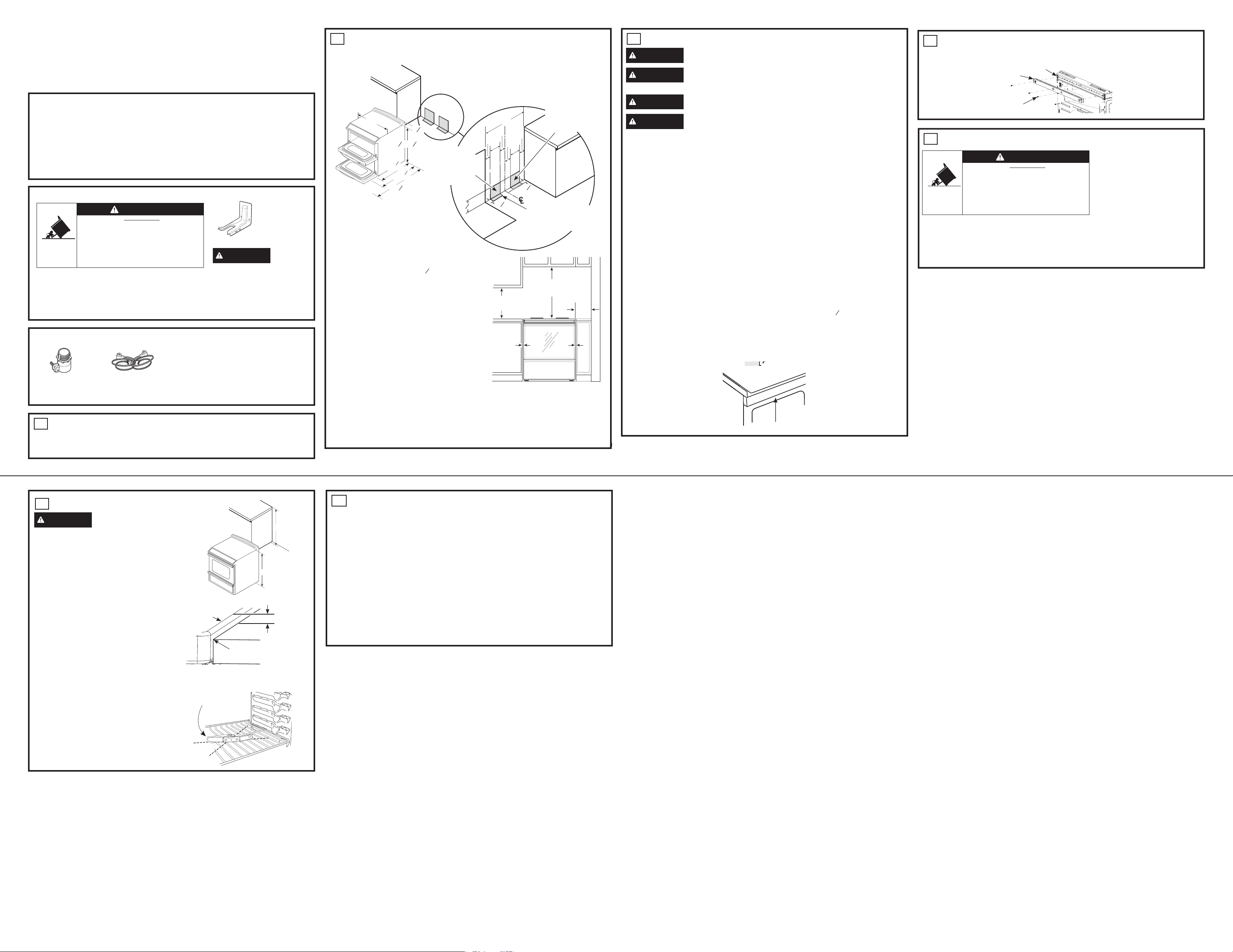
PREPARE THE OPENING (FOR INDOOR USE ONLY)
See illustrations for all rough-in and spacing dimensions. The range may be placed with 0”
clearance (flush) at the back wall and side walls of the cabinet.
NOTE: Use a 4’ power cord to prevent interference with
the storage drawer. Power cords 4
1
2’ to 6’ long may
have to be dressed to allow for proper drawer closing.
MINIMUM DIMENSIONS BETWEEN COOKTOP,
WALLS AND ABOVE THE COOKTOP:
A. Make sure the wall covering, countertop, flooring
and cabinets around the range can withstand the
heat (up to 200°F) generated by the range. 0” to
cabinets below cooktop and at the range back.
B. Allow 30” minimum clearance between surface units
and bottom of unprotected wood or metal cabinet, or
allow a 24” minimum when bottom of wood or metal
cabinet is protected by no less than 1/4” thick flame
retardant millboard covered with not less than No.
28 MSG sheet metal, (.015”), .015” thick stainless
steel, .024” aluminum or .020” copper.
C. This appliance has been approved for 0” spacing to
adjacent surfaces above the cooktop. However, a 6” minimum spacing to surfaces less than 15”
above the cooktop and adjacent cabinet is recommended to reduce exposure to steam, grease
splatter and heat.
To reduce the risk of burns or fire when reaching over hot surface elements, cabinet storage space
above the cooktop should be avoided. If cabinet storage space is to be provided above the cooktop,
the risk can be reduced by installing a range hood that projects at least 5” beyond the front of the
cabinets. Cabinets installed above the cooktop must be no deeper than 16”.
3
ELECTRICAL REQUIREMENTS
WARNING
This appliance must be properly grounded.
WARNING
All new constructions, mobile homes, recreational vehicles and installations
where local codes do not allow grounding through neutral, require a 4-conductor UL-listed range cord.
WARNING
To prevent fire or shock, do not use an extension cord with this appliance.
WARNING
To prevent shock, remove house fuse or open circuit breaker before
beginning installation.
We recommend you have the electrical wiring and hookup of your range connected by a qualified
electrician. After installation, have the electrician show you how to disconnect power from the range.
You must use a single-phase, 120/208 VAC or 120/240 VAC, 60 hertz electrical system. If you
connect to aluminum wiring, properly installed connectors approved for use with aluminum wiring
must be used.
Effective January 1, 1996, the National Electrical Code requires that new construction (not existing)
utilize a 4-conductor connection to an electric range. When installing an electric range in new
construction, mobile home, recreational vehicle, or an area where local codes prohibit grounding
through the neutral conductor, refer to the section on four-conductor branch circuit connections.
Check with your local utilities for electrical codes which apply in your area. Failure to wire your oven
according to governing codes could result in a hazardous condition. If there are no local codes,
your oven must
be wired and fused to meet the National Electrical Code, NFPA No. 70 – latest
edition, available from the National Fire Protection Association.
This appliance must be supplied with the proper voltage and frequency, and connected to an
individual, properly grounded, 40 amp (minimum) branch circuit protected by a circuit breaker or
time-delay fuse.
Use only a 3-conductor or a 4-conductor UL-listed range cord. These cords may be provided with
ring terminals on wire and a strain relief device.
A range cord rated at 40 amps with 125/250 minimum volt range is required. A 50 amp range cord
is not recommended but if used, it should be marked for use with nominal 1
3
8” diameter connection
openings. Care should be taken to center the cable and strain relief within the knockout hole to
keep the edge from damaging the cable.
The rating plate is located on the oven frame or on the side of the drawer frame.
NOTE: Use of automatic, wireless or wired external switches that shut off power to the appliances,
are not recommended for this product.
5
ANTI-TIP DEVICE INSTALLATION
To reduce the risk of tipping the
range, the range must be secured by
a properly installed anti-tip bracket.
See installation instructions shipped
with the bracket for complete details
before attempting to install.
To check if the bracket is installed and
engaged properly, look underneath
the range to see that the rear leveling
leg is engaged in the bracket. On some models, the storage drawer or kick panel can be removed
for easier inspection. If visual inspection is not possible, slide the range forward, confirm the anti-
tip bracket is securely attached to the floor or wall, and slide the range back so the leveling leg is
under the anti-tip bracket. If the range is pulled from the wall for any reason, always repeat this
procedure to verify the range is properly secured by the anti-tip bracket. Never completely remove
the leveling legs or the range will not be secured to the anti-tip bracket.
7
FINAL INSTALLATION CHECKLIST
• Check to make sure the circuit breaker is closed (RESET) or the circuit fuses are replaced.
• Be sure power is in service to the building.
• Check that all packing materials and tape have been removed. This will include tape on metal
panel under control knobs (if applicable), adhesive tape, wire ties, cardboard and protective
plastic. Failure to remove these materials could result in damage to the appliance once the
appliance has been turned on and surfaces have heated.
• Check that the door and drawer are parallel to each other and that both operate smoothly. If they
do not, see the Owner’s Manual for proper replacement.
• Check to make sure that the rear leveling leg is fully inserted into the Anti-Tip bracket and that the
bracket is securely installed.
OPERATION CHECKLIST
• Check that the oven control operates properly. If the oven control does not operate properly,
recheck the wiring connections.
• Be sure all range controls are in the OFF position before leaving the range.
Anti-Tip Bracket
Kit Included
INSTALLATION INSTRUCTION
29-6132 05-17 GEA
CCHS995
WARNING
Before
beginning the installation, switch power
off at service panel and lock the service
disconnecting means to prevent power
from being switched on accidentally.
When the service disconnecting means
cannot be locked, securely fasten a
prominent warning device, such as a
tag, to the service panel.
• A child or adult can tip the range and be killed.
• Install the anti-tip bracket to the wall or floor.
• Engage the range to the anti-tip bracket by sliding the
range back such that the foot is engaged.
• Re-engage the anti-tip bracket if the range is moved.
• Failure to do so can result in death or serious burns
to children or adults.
Tip-Over Hazard
WARNING
A
C
B
A
C
Both
Sides
30”
Install the
outlet box
on either
side of the C
L
36
1
4” ±
1
4”
1
1
8”
43
7
8”
26
7
8
”
w/o handle
29
1
2”
with handle
30”
3”
3”
3”
9”
8”
4”
7
1
2”
2
1
4”
2
1
4”
Recommended
area for
through-the-
Wall connection
of pipe stub and
shut-off valve.
Recommended area
for through-the-floor
connection of pipe stub
and shut-off valve.
Recommended
acceptable
electrical outlet
area. Orient the
electrical receptacle
so the length is
parallel to the floor.
• A child or adult can tip the range and be killed.
• Install the anti-tip bracket to the wall or floor.
• Engage the range to the anti-tip bracket by sliding the
range back such that the foot is engaged.
• Re-engage the anti-tip bracket if the range is moved.
• Failure to do so can result in death or serious burns
to children or adults.
Tip-Over Hazard
WARNING
6
LEVEL THE RANGE
WARNING
Never completely
remove the leveling leg as the range will not
be secured to the anti-tip device properly.
A. Plug in the unit.
B. Measure the height of your countertop at the
rear of the opening (X).
C. Adjust two rear leveling legs so that the rear
of cooktop is at the same height or higher
than the counter (Y).
D. Slide unit into place.
E. Install oven shelves in the oven and position
the range where it will be installed.
F. Check for levelness by placing a spirit
level on one of the oven shelves. Take two
readings—with the level placed diagonally
first in one direction and then the other.
G. Adjust front leveling legs until the range is
level.
H. Look under the un
it and verify that the rear
leg is fully engaged with the anti-tip device. If
not, remove the unit and adjust the height of
the rear leg so that it is properly engaged.
Spirit level
NOTE: Cooktop must be at or above counter.
Cooktop
0” or Greater
Counter
X
Y
Rating plate
DOUBLE OVEN
R
nter
he oven frame or
ireless or wired
r this product.
F
FT
FT
FT
DOUBLEOUBL
4
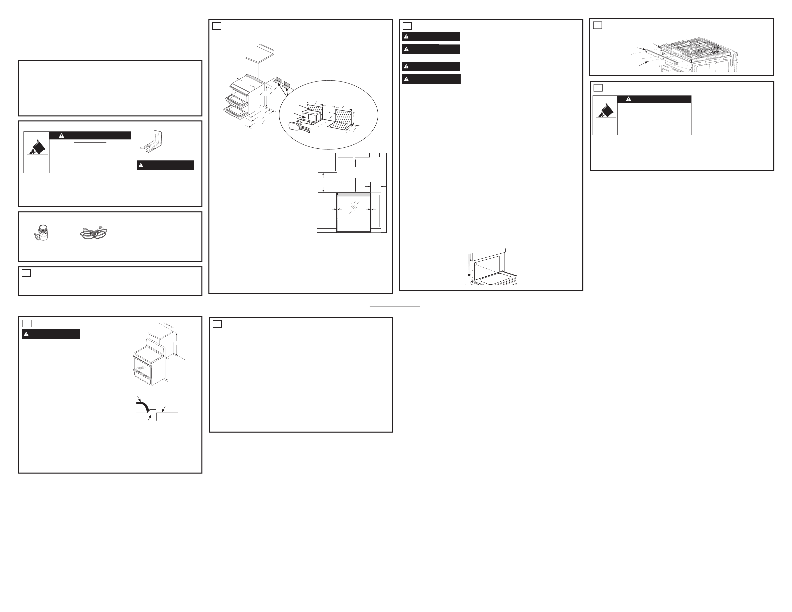
REAR TRIM INSTALLATION
For all installations, install the required rear trim to back of range with 4 screws provided.
Screws
Rear Trim
Back of
Range
Au Canada, appelez au 1-800-626-2000 ou visitez le www.electromenagersge.ca.
AVANT DE COMMENCER
Lisez ces consignes complètement et attentivement.
• IMPORTANT — Gardez ces instructions
pour l’usage de l’inspecteur local.
•
IMPORTANT — Respectez tous les
codes et règlements.
• Remarque pour l’Installateur – Laissez ces
instructions au client.
• Remarque pour le client
– Gardez ces
consignes pour consultation ultérieure.
• Niveau de compétence – Cet appareil doit
être installé par un installateur ou un
• C’est à l’installateur qu’incombe la
responsabilité d’une installation correcte.
• Une panne du produit due à une installation
incorrecte n’est pas couverte par la garantie.
POUR VOTRE SÉCURITÉ :
Si vous n’avez pas reçu un support anti-renversement avec
votre achat, appelez au 1.800.626.8774 pour en recevoir un
sans frais. (Au Canada, appelez au 1.800.561.3344). Pour les
instructions d’installation du support, visitez le :.
www.GEAppliances.com. (Au Canada,
Instructions d’Installation
Cuisinières Électriques Encastrables
MATÉRIAUX DONT VOUS POURRIEZ AVOIR BESOIN OUTILS DONT VOUS AUREZ BESOIN
(40 A homologué UL)
Câble de 4" de long de 4 fils
OU Câble de 4" de long de 3 fils
Embout à Pression
(Seulement pour
l'Installation de Conduits)
1
ENLEVEZ LES MATÉRIAUX D’EMBALLAGE : Ne pas enlever les
matériaux d’emballage pourrait donner lieu à des dommages à l’appareil. Enlevez tous les
morceaux d’emballage du four, des grilles, des éléments de chauffage et du tiroir. De plus,
enlevez la pellicule et les étiquettes protectrices sur la porte extérieure, la surface de cuisson
Perceuse avec Mèche
Lunettes de Sécurité
Clé à Molette
Niveau
Cisailles à Tôle
Ruban à Mesurer
Pince
Tournevis à Écrou
2
PRÉPARER L’OUVERTURE (POUR UTILISATION À L’INTÉRIEUR SEULEMENT)
Voir les illustrations pour toutes les dimensions de base et d’espacement. La cuisinière peut être
placée avec un dégagement de 0" (alignée) au mur arrière et aux murs latéraux des armoires.
NOTE : Utilisez un câble électrique de 4" pour éviter qu’il
ne touche au tiroir de rangement. Les fils électriques de 4½" à
6" de long peuvent devoir être alignés pour permettre que le
DIMENSIONS MINIMALES ENTRE LA SURFACE DE CUISSON,
LES MURS ET AU-DESSUS DE LA SURFACE DE CUISSON :
A. Assurez-vous que les revêtements muraux, les dessus
de comptoir, le revêtement de sol et les armoires autour
de la cuisinière peuvent résister à la chaleur (jusqu’à
200ºF) produite par la cuisinière.
B. Prévoyez un espace minimum de 30" entre la surface
de l’appareil et la partie inférieure sans protection de
l’armoire en bois ou en métal, ou prévoyez un minimum
de 24" lorsque la partie inférieure de l’armoire en bois
ou en métal est protégée par au moins 1/4" d’épaisseur
de polymère retardateur recouvert d’au moins une
feuille de métal MSG No.28, (.015"), .015" d’épaisseur
C.
Cet appareil a été approuvé pour un espacement de 0"
aux surfaces adjacentes au-dessus de la surface de
cuisson. Cependant, un espacement minimal de 6" aux
surfaces de moins de 15" au-dessus de la surface de
Pour réduire le risque de brulures ou d’incendie lorsque vous tendez le bras au-dessus des éléments
de surface chauds, l’espace de rangement des armoires au-dessus de la surface de cuisson devrait
être évité. Si l’espace de rangement des armoires doit être fourni au-dessus de la surface de cuisson,
le risque peut être réduit en installant une hotte afin de projeter d’au moins 5" au-delà du devant des
3
BESOINS ÉLECTRIQUES
AVERTISSEMENT
Cet appareil doit être correctement mis à la terre.
AVERTISSEMENT
Toutes les nouvelles constructions, maisons mobiles, véhicules
mise à la terre par le fil neutre, exigent un branchement à 4 conducteurs homologué UL.
AVERTISSEMENT
Pour éviter les risques d’incendie ou un choc électrique, n’utilisez
AVERTISSEMENT
Pour éviter les chocs électriques, retirez le fusible de la maison ou
Nous vous recommandons de faire raccorder le câblage électrique et la connexion de votre cuisinière
par un électricien qualifié. Après l’installation, demandez à l’électricien de vous montrer comment
Vous devez utiliser un système électrique de conducteur monophasé, 120/208 VAC ou 120/240 VAC
de 60 Hertz. Si vous raccordez à un câblage en aluminium, vous devez utiliser des connecteurs
installés correctement approuvés pour une utilisation avec un câblage en aluminium.
En vigueur depuis le 1er janvier 1996, le Code National Électrique Américain exige que les nouvelles
constructions (non existantes) utilisent un raccord 4 conducteurs à une cuisinière électrique. Lorsque
vous installez une cuisinière électrique dans une nouvelle construction, une maison mobile, un
véhicule récréatif, ou un espace où les codes locaux interdisent la mise à la terre par le fil conducteur
Vérifiez avec votre fournisseur local pour les codes électriques qui s’appliquent dans votre région. Ne
pas raccorder votre four conformément aux codes peut provoquer des conditions hasardeuses. S’il
n’y a pas de codes locaux, votre four doit être raccordé et fusionné pour respecter le Code National
Électrique Américain, NFPA No. 70 – dernière édition, disponible par la National Fire Protection
Cet appareil doit être approvisionné avec le voltage et la fréquence correcte, et raccordé à un circuit
de dérivation individuel de 40 ampères (minimum), correctement mis à la terre, et protégé par un
disjoncteur ou un fusible temporisé.
Utilisez seulement un branchement à 3 ou 4 conducteurs homologué UL. Ces câbles peuvent être
munis de cosses à œillet sur le fil et d’un dispositif de soulagement de la tension.
Un branchement classé à 40 ampères avec un minimum de portée de volts de 125/250 est requis. Un
branchement de 50 ampères n’est pas recommandé mais si utilisé, devrait être marqué pour
utilisation avec des ouvertures de raccord d’un diamètre nominal de 1 3/8". Des précautions devraient
être prises pour centrer le câble et le dispositif de soulagement de la tension à l’intérieur de la
La plaque signalétique est située sur le châssis du four ou sur le côté du châssis du tiroir.
NOTE : L’utilisation d’interrupteurs externes automatiques, sans fils ou connectés qui coupent
l’alimentation aux appareils, n’est pas recommandée pour ce produit.
5
INSTALLATION DU DISPOSITIF ANTI-RENVERSEMENT
Pour réduire le risque de renversement de la
cuisinière, celle-ci doit être fixée par un support
anti-renversement correctement installé. Voir les
les instructions d’installation expédiées avec le
support pour les détails complets avant de
tenter de l’installer.
Pour vérifier si le support est installé et
enclenché correctement, vérifiez sous la
cuisinière pour voir si le pied de nivèlement arrière est enclenché dans le support. Sur certains modèles, le
tiroir de rangement ou le panneau de protection peut être enlevé pour faciliter l’inspection. Si une inspection
visuelle n’est pas possible, glissez la cuisinière vers l’avant, vérifiez que le support anti-renversement soit
fixé fermement au sol ou au mur et glissez la cuisinière vers l’arrière pour que le pied de nivèlement soit
sous le support anti-renversement. Si la cuisinière est éloignée du mur pour une raison quelconque, répétez
toujours cette procédure pour vous assurez que la cuisinière est correctement fixée au support anti-
renversement. N’enlevez jamais entièrement les pieds de nivèlement ou alors la cuisinière ne sera pas
• Un enfant ou un adulte peut renverser la cuisinière et être
• Installez le support anti-renversement au mur ou au sol.
• Enclenchez la cuisinière au support anti-renversement en
glissant la cuisinière vers l’arrière afin que le pied soit
• Réenclenchez le support anti-renversement si la cuisinière
• Le non-respect de cet avertissement peut entrainer la mort
ou des brulures graves aux enfants ou aux adultes.
Danger de Renversement
AVERTISSEMENT
7
LISTE DE VÉRIFICATION D’INSTALLATION FINALE
• Vérifiez, pour vous assurez, que le disjoncteur est fermé (RESET/RÉENCLENCHER) ou que les
• Assurez-vous qu’il y a de l’électricité.
• Vérifiez que tous les matériaux et ruban adhésif ont été retirés. Ceci comprendra le ruban adhésif
sur le panneau en métal sous les boutons de commande (le cas échéant), le ruban adhésif, les
attaches métalliques, le carton et le plastique de protection. Ne pas retirez ces matériaux pourrait
donner lieu à des dommages à l’appareil une fois que l’appareil aura été mis en marche et que les
• Vérifiez que la porte et le tiroir sont parallèles l’un l’autre et que les deux fonctionnent bien. Si non,
voir le Guide de l’Utilisateur pour une pièce de remplacement appropriée.
• Vérifiez, pour vous assurez, que le pied de nivèlement arrière est complètement inséré dans le
support anti-renversement et que le support est installé fermement.
LISTE DE VÉRIFICATION DE FONCTIONNEMENT
• Vérifiez que la commande du four fonctionne correctement. Si la commande du four ne fonctionne
pas correctement, revérifiez le raccord des fils.
• Assurez-vous que les commandes de la cuisinière sont à la position OFF (ÉTEINT) avant de vous
Support
Nécessaire Inclus
INSTRUCTIONS D’INSTALLATION
29-6132 01-17 GEA
CCHS995
AVERTISSEMENT
Avant de commencer l’installation, coupez
l’électricité au panneau de service et
verrouillez les dispositifs de coupure de
courant pour empêcher l’électricité d’être
mise en marche accidentellement. Lorsque
les dispositifs de coupure de courant ne
peuvent être verrouillés, attachez fermement
un dispositif d’avertissement visible, tel
• Un enfant ou un adulte peut renverser la cuisinière et être tué.
• Installez le support anti-renversement au mur ou au sol.
• Enclenchez la cuisinière vers l’arrière afin que le pied soit
• Réenclenchez le support anti-renversement si la cuisinière
• Le non-respect de cet avertisement peut entrainer la mort
ou des brulures graves aux enfants ou aux adultes.
Danger de Renversement
AVERTISSEMENT
A
C
B
A
C
Deux
Côtés
Câble
Mur
Plancher
7”
5”
Prise
Électrique
2
1
4”
7
1
2”
7
1
2”
3
1
2”
C de la cuisinière
L
Installez la
prise électrique
de chaque côté du
C
L
30”
36
1
4” ±
1
4”
1
1
8
43
7
8”
26
7
8”
sans la poignée
29
1
2”
avec la poignée
Plaque signalétique
FOUR DOUBLE
6
NIVELEZ LA CUISINIÈRE
AVERTISSEMENT
N’enlevez
entièrement le pied de nivèlement ou bien la
cuisinière ne sera pas fixée correctement au
A. Branchez l'appareil.
B. Mesurez la hauteur de votre comptoir à
l’arrière de l’ouverture (X).
C. Ajustez les deux pieds de nivèlement arrière
afin que l’arrière de la surface de cuisson soit
à la même hauteur ou plus élevé que le
D. Glissez l’appareil en place.
E. Installez les grilles du four dans le four et
positionnez la cuisinière là où elle sera
F. Vérifiez l’égalité en plaçant un niveau sur une
des grilles du four. Prenez deux lectures –
premièrement avec le niveau placé
diagonalement dans un sens et puis dans
G. Ajustez les pieds de nivèlement avant jusqu’à
ce que la cuisinière soit nivelée.
H. Regardez sous l’appareil et vérifiez que le pi
ed
arrière soit complètement enclenché avec le
dispositif anti-renversement. Si non, retirez
l’appareil et ajustez la hauteur du pied arrière
X
Y
NOTE : La surface de
cuisson doit être à la même
Grille
Surface de cuisson
Comptoir
DR
FT
FT
FT
technicien qualifié.
enclenché.
a été déplacée.
Anti-Renversement
www.GEApplicances.ca).
qu’une étiquette, au panneau de service.
de 1/8”
de 1/4”
et le panneau de configuration.
tiroir ferme correctement.
d’acier inoxydable, .024" d’aluminium ou .020" de cuivre.
cuisson et aux armoires adjacentes est recommandé
pour réduire l’exposition à la vapeur, aux éclaboussures
de graisse et à la chaleur.
armoires. Les armoires installées au-dessus de la surface de cuisson ne doivent être plus profondes
que 16".
récréatifs et installations où les codes locaux ne permettent pas la
pas de rallonge avec cet appareil.
ouvrez le disjoncteur avant de débuter l’installation.
couper l’alimentation de la cuisinière.
neutre, consultez la section sur les raccords de circuit de dérivation à quatre conducteurs.
Association.
débouchure pour empêcher le bord d’endommager le câble.
tué.
enclenché.
a été déplacée.
correctement fixée au support anti-renversement.
jamais
dispositif anti-renversement.
comptoir (Y).
installée.
l’autre.
afin qu’il soit correctement enclenché
hauteur ou plus élevée que le
comptoir.
fusibles ont été remis en place.
surfaces auront chauffées.
éloigner de la cuisinière.
4
INSTALLATION DU COMPLEMENT ARRIÈRE
Pour toute installation, installez le complement arrière requis a l’aide des 4 vis fournis.
Les Vis
Complement
arrière
L’arrière
de cuisinière
Questions? Au Canada, appelez au 1.800.561.3344 ou visitez le www.GEAppliances.ca.