
Loading ...
Loading ...
Loading ...
6
Mr. Heater | Portable Propane Heater Operating Instructions and Owner’s Manual
Figure 6
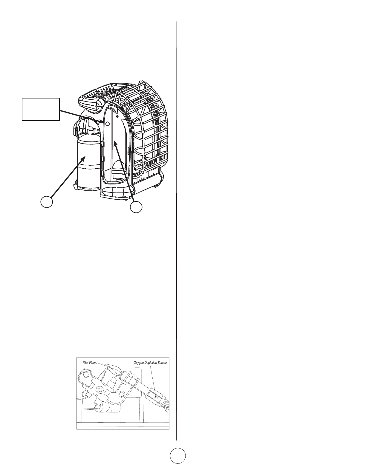
Storage Compartments
The MH12HB has two storage compartments, with access
doors, on the left side of the heater. The pulse light
button is located in the forward compartment (Ref.A).
This compartment can also be used to store small tools or
spare fuel filters (not included).
The rear compartment (Ref.B) can be used to store a
spare 1# tank (not included).
PULSE IGNITION:
The Pulse Ignition Button is located in the front stor-
age compartment (Ref.5).
Unscrew the button cap to install the “AA” battery
(included), with positive end toward the button.
MAINTENANCE:
Always keep the heater area clear and free from combus-
tible materials, gasoline and other flammable vapors and
liquids.
Keep the vent areas (slots in the bottom and the top at the
front and rear of heater) clear at all times.
and without a noticeable flame. A blue flame that rolls out
at the top of the ceramic tile indicates an accumulation of
dust, lint or spider webs inside the casing assembly and
main burner assembly. If the pilot is yellow or the burner
has a noticeable flame, cleaning may be required. Use the
following procedure to inspect the casing assembly and
main burner assembly.
It is necessary to periodically check the burner orifice and
burner venturi tube to make sure they are clear of insects/
nests or spider webs that may accumulate over time. A
clogged tube can lead to a fire.
1 Allow heater to thoroughly cool before performing any
maintenance.
2 Remove disposable 1 lb. cylinder from heater or turn
OFF gas supply at remote cylinder valve, and disconnect
hose from heater.
3 Remove (4) four screws that secure the rear cover to
the Heater.
4 Pivot cover outward from bottom. Release from 2 top
clips. Set aside.
5 Remove (4) four burner retaining screws and fuel line
from burner assembly. Remove burner assembly from
back of housing.
6 Inspect interior of housing for accumulation of dust, lint
or spider webs. If necessary, clean interior housing with
a vacuum cleaner or apply air pressure. Do not damage
any components within the housing assembly when you
are cleaning.
7 Inspect and clean main burner orifice (threaded into
orifice holder). Orifice holder is attached to the burner
assembly venturi with (2) two screws.
8 Inspect and clean pilot (mounted to bracket) by using a
vacuum or apply air pressure through the holes in the
pilot indicated by the arrows in Figure 5.
WARNING: Never use needles, wires, or similar cylin-
drical objects to clean the pilot to avoid damaging the
calibrated orifice that controls the gas flow.
9 Apply air pressure (max. 30 psi.) into ceramic tile of
burner assembly and the venturi tube (ref. item #16) to
remove dust, lint or spider webs.
10 Reassemble main burner orifice holder onto the burner
assembly.
11 Reinstall burner assembly into the heater housing
12 Reinstall fuel line and check for leaks.
13 Install heater back cover.
B
A
Pulse Ignition
Button
Visually inspect the pilot flame and burner periodically dur-
ing use. The pilot flame should be blue in color (not yellow)
and will extend beyond the thermocouple. The flame will
surround the thermocouple just below the tip, see Figure 6.
A slight yellow flame may occur where the pilot flame
and main burner flame meet. The burner should be bright
orange (with a slight blue color around the border, a red-
orange haze that is visible on the ceramic tile is acceptable)
Figure 5
Loading ...
Loading ...
Loading ...