Model #: 43520
EXECUTIVE CHAIR
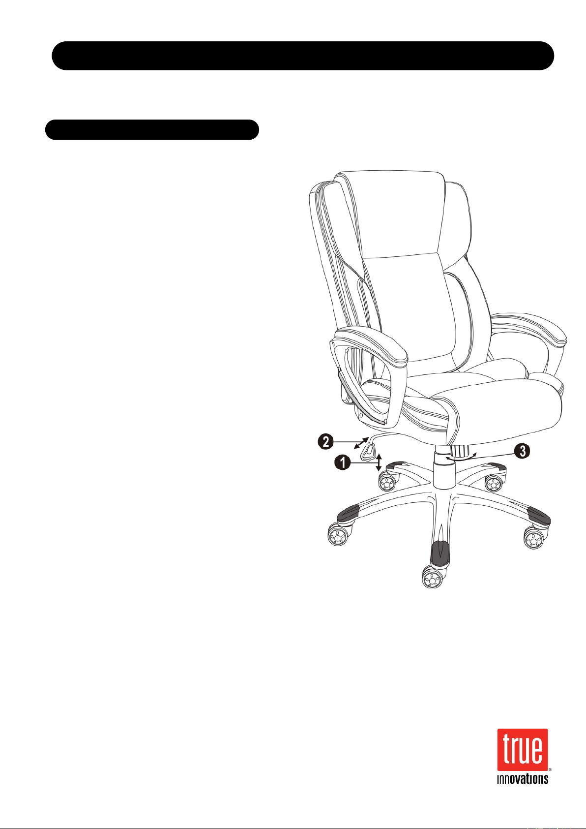
1. To Adjust Seat Height:
While seated, lean forward and reach under the
right side of the chair to find the handle. Lift the
handle and raise your body up slightly to allow the
chair to rise to the desired height. To lower the
seat, lift the handle while seated. The chair will
descend until the handle is released or the chair
reaches the bottom position.
2. To Operate Tilt Lockout:
While seated, reach under the right side of the
chair to find the height adjustment handle. Pull the
handle all the way out (away from the seat plate)
to allow the chair to tilt backwards. To lock the
chair in the upright or vertical position, sit upright
and push the handle in towards the seat plate.
3. To Adjust Tension on The Tilt
Mechanism:
Reach under the front center of the chair, grasp
the round knob and turn counter- clockwise to
make the tilt mechanism firmer (stiffer). To make
the tilt mechanism less firm, turn the knob
clockwise until the desired resistance is found.
OPERATING INSTRUCTIONS
Model #: 43520
EXECUTIVE CHAIR
Part # Description Quantity
1.
2.
3.
4.
5.
6A.
6B.
7.
8.
9.
10.
11.
12.
13.
14.
Casters
5 Star Base
Telescoping Cover
Gas Lift
Seat Plate
Left Arm
Right Arm
Seat Cushion
Back Cushion
1-5/8” Big Screws
7/8” Big Screws
1” Small Screws
1-1/2” Small Screws
Black Plastic Caps
Allen Keys
5
1
1
1
1
1
1
1
1
2
2
6
2
8
2
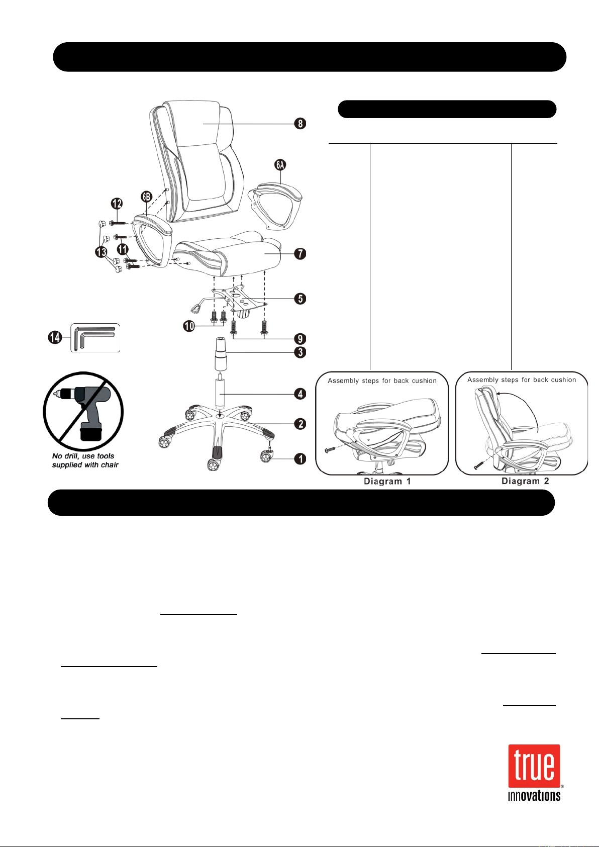
A. Remove all parts from carton and separate them into part number groups as indicated in parts list.
B. To begin assembly, place 5 Star Base (2) upside down and insert Casters (1) into bottom of Base (2).
C. Turn Base (2) right side up on the floor and insert Gas Lift (4) into center hole on Base (2).
D. Place Telescoping Cover (3) over the Gas Lift (4) and rest it on the Base (2).
E. Attach Seat Plate (5) onto the bottom of Seat Cushion (7) (with front of seat plate facing front of seat cushion)
by using 1-5/8" Big Screws (9) in the front holes of Seat Plate (5) and 7/8” Big Screws (10) in the rear holes
of Seat Plate (5) and
tighten screws.
F. Place the assembled Seat Cushion (7) with Seat Plate (5) on top of Gas Lift (4) and press down until fully
engaged.
G. Fasten Arms (6A & 6B) onto sides of Seat Cushion (7) by using 1” Small Screws (11).
Do not tighten
screws completely.
H. Place the Back Cushion (8) flat Between Arms (6A & 6B), and use 1” Small Screws (11) to locate lower
screw holes on both Arms (6A & 6B) & Back Cushion (8) as Diagram 1. Push the Back Cushion (8) up to a
vertical position and attach the Arms (6A & 6B) by using 1-1/2” Small Screws (12) as Diagram 2.
Tighten all
screws.
I. Place the Black Plastic Caps (13) into arm holes once screws have been tightened.
J. Periodically (every 90 days) make sure that the screws are still fully tightened.
ATTENTION: Be certain that all screws are fully tightened before using chair.
PARTS LIST
ASSEMBLY INSTRUCTIONS