Installation Applications
This product is designed for operation in vehicles with 12 volt, negative-ground
electrical systems. Using this product in systems with positive ground and/or
voltages other than 12 volts may result in damage to the product and will void the
warranty. This product is not certified or approved for use in aircraft.
Safety Considerations
• Install this product in a dry, well-ventilated location that does not interfere with your
vehicle’s safety equipment (air bags, seat belt systems, ABS brake systems, etc.).
• Securely mount this product so that it does not come loose in the event of a
collision or sudden jolt to the vehicle.
• Check before drilling to make sure that you will not be drilling into a gas tank,
brake line, wiring harness or other vital vehicle system.
• Do not run system wiring outside or underneath the vehicle. This is an extremely
dangerous practice, which can result in severe damage/injury.
• Use good quality crimp connectors (or solder with heat shrink tubing) when
making connections to a vehicle’s electrical system.
• Take the necessary precautions when making connections to the vehicle’s battery.
• Protect all system wires from sharp metal edges and wear by carefully routing
them, tying them down and using grommets and loom where appropriate.
Failure to do so may result in a dangerous short circuit.
Planning Your Installation
It is important that you take the time to read this manual and that you plan
your installation carefully. It is very easy to damage expensive vehicle systems
in modern automobiles. Never assume that you have found appropriate wires
without consulting a reliable wiring diagram or without performing signal testing
with proper test equipment. If you are uncomfortable or unfamiliar with reading
diagrams or testing signals, please enlist the services of your authorized JL Audio
dealer to perform the installation.
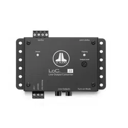
Product Description
The LoC™ 22 is an active two-channel processor engineered
to adapt the outputs from factory audio systems for use
with aftermarket amplifiers and signal processors.
The LoC™ 22 is equipped with the following features:
1. Fully active, all analog circuit design by Bruce Macmillan, handles
powerful factory amplifier outputs, up to 40 volts per channel
2. Differential-balanced input architecture offers noise rejection and
compatibility with most analog outputs from OEM source units and amplifiers
3. Dual range input load switch for maximum compatibility with OEM amplifiers
4. One stereo pair of crystal-clear, line-level RCA output jacks (up to 8V RMS)
5. Automatic turn-on via DC-Offset or Signal-Sensing
6. A dedicated 12V remote turn-on output to activate
aftermarket signal processors or amplifiers (similar to an
aftermarket head unit’s remote turn-on lead)
7. Onboard LED clipping indicator for quick & easy output level setting
What’s Included
(1) LoC™ 22 Line Output Converter
(1) 3-pin Power Connector plug
(1) 4-pin Input plug
(1) User manual
Installation Procedure/Making Connections
The LoC™ 22 uses removable plugs for making power and input signal
connections. Receptacles in each plug accept up to 16 AWG wire. To attach wires,
remove the plugs from the LoC™ 22 and use a small flathead screwdriver to back
out the set screws. Strip 1/4 inch (6 mm) of insulation from the end of each wire
and insert the bare wire into the receptacle, seating it firmly so that no wire is
exposed. While holding each wire in place, tighten the set screw firmly, taking care
not to strip the head of the screw.
Use caution to ensure correct polarity and wire placement of the Power and
Input signal connections.
Make sure to observe proper orientation when inserting the plugs into the
LoC™ 22. Each plug is keyed to fit in one direction only. When inserted
correctly, the set screws should be facing up.
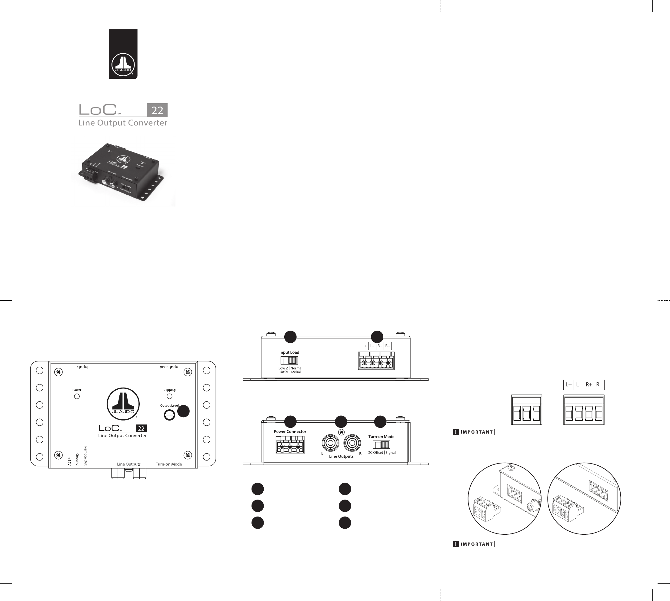
LoC™ 22 Top View LoC™ 22 Input Panel
LoC™ 22 Power Connector / Line Outputs Panel
1
Power Connector
4
Line Outputs
2
Input Connector
5
Turn-on Mode
3
Input Load
6
Output Level
+12V
Ground
Remote Out
1 4 5
3 2
OWNER’S MANUAL
6
Limited Warranty – Electronics (USA)
JL Audio warrants this product to be free of defects in materials and workmanship for a period of two
(2) years from the original date of purchase. This warranty is not transferable and applies only to the
original purchaser from an authorized JL Audio dealer. Should service be necessary under this warranty
for any reason due to manufacturing defect or malfunction, JL Audio will (at its discretion), repair or
replace the defective product with new or remanufactured product at no charge. Damage caused by
the following is not covered under warranty: accident, misuse, abuse, product modification or neglect,
failure to follow installation instructions, unauthorized repair attempts, misrepresentations by the
seller. This warranty does not cover incidental or consequential damages and does not cover the cost
of removing or reinstalling the unit(s). Cosmetic damage due to accident or normal wear and tear is not
covered under warranty.
Warranty is void if the product’s serial number has been removed or defaced.
Any applicable implied warranties are limited in duration to the period of the express warranty as
provided herein beginning with the date of the original purchase at retail, and no warranties, whether
express or implied, shall apply to this product thereafter. Some states do not allow limitations on
implied warranties, therefore these exclusions may not apply to you. This warranty gives you specific
legal rights, and you may also have other rights, which vary from state to state.
If you need service on your JL AUDIO product:
All warranty returns should be sent to JL Audio ’s Electronics Service Facility freight-prepaid through an
authorized JL Audio dealer and must be accompanied by proof of purchase (a copy of the original sales
receipt). Direct returns from consumers or non-authorized dealers will be refused unless specifically
authorized by JL Audio with a valid return authorization number. Warranty expiration on products
returned without proof of purchase will be determined from the manufacturing date code. Coverage
may be invalidated as this date is previous to purchase date. Non-defective items received will be
returned freight-collect. Customer is responsible for shipping charges and insurance in sending the
product to JL Audio. Freight damage on returns is not covered under warranty.
For Service Information in the U.S.A. please call
JL Audio Customer Service:
(954) 443-1100
9:00 AM – 5:30 PM (Eastern Time Zone)
JL Audio, Inc.
10369 North Commerce Pkwy.
Miramar, FL 33025
(Do not send product for repair to this address)
International Warranties:
Products purchased outside the United States of America are covered only
by that country’s distributor and not by JL Audio, Inc.
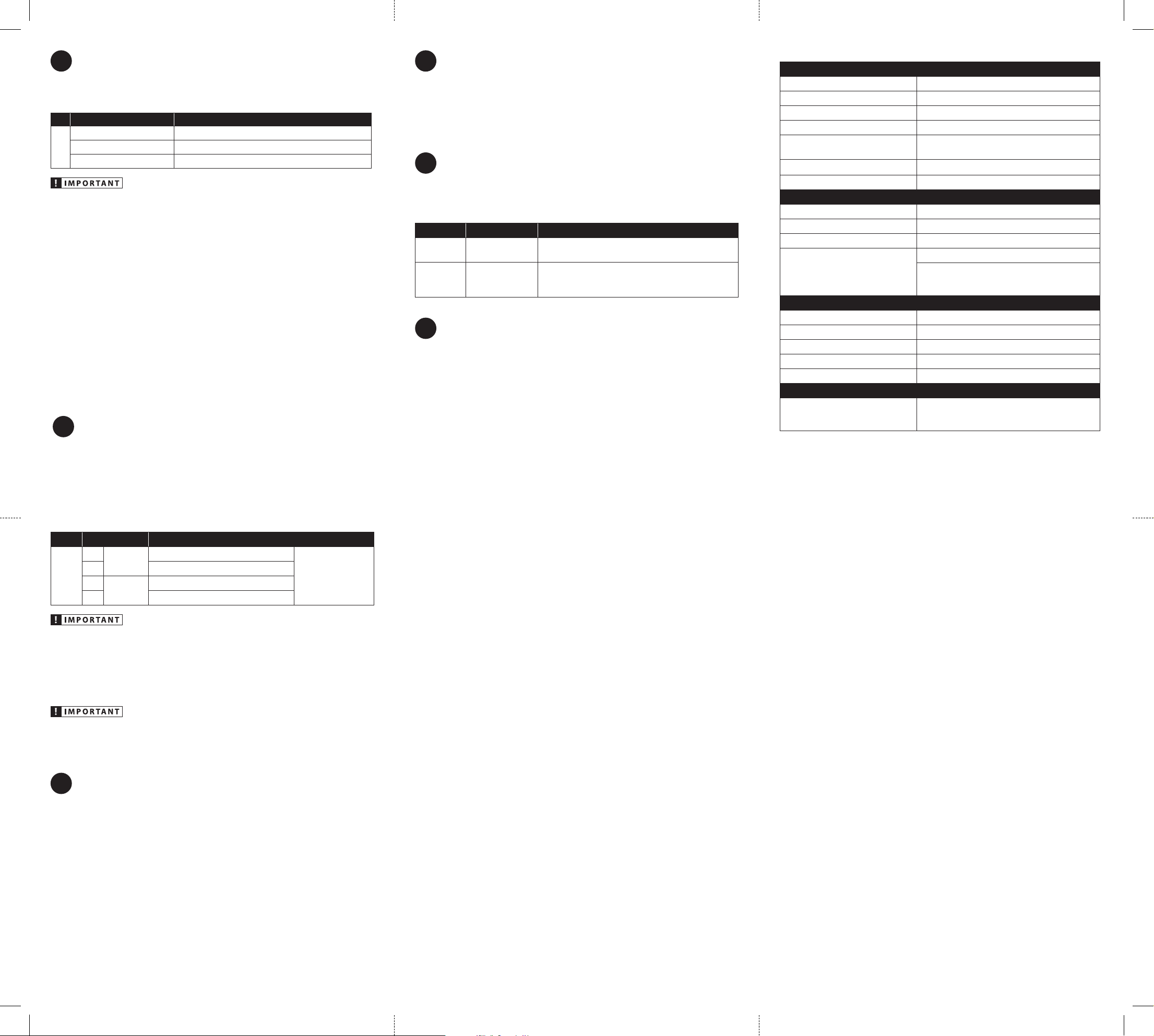
Specifications
Electrical Specications
Power Supply Type Switching, MOSFET PWM, Regulated
Operating Voltage 9 – 16V DC
Standby / Operating Current Draw < 1.6 mA / 0.13 A at 13.8V
Frequency Response 3 Hz - 32 kHz (+0 dB, -1dB)
S/N Ratio @ 2V RMS
Gain at Min: 118 dB
Gain at Max: 103 dB (20 kHz Bandwidth)
Remote Output Capacity 100 mA (maximum)
Recommended Fuse Value / Type 1 A / Fast-Acting, ATO/ATC or similar
OEM Input Section
Number of Input Channels / Type Two / Dierential-Balanced
Input Voltage 40V RMS per channel (maximum)
Input Impedance Normal: 20 kΩ / Low Z: 60 Ω
Turn-On Threshold
DC-Oset: 4.5 V
Signal-Sensing: 5 mV On/3.5 mV O at
1 kHz (Left Input)
Output Section
Number of Output Channels / Type Two / Unbalanced, via RCA Jacks
Max. Unclipped Output 8V RMS
Output Impedance 450 ohms
Gain Range -27.3 dB (full CCW) to +3.2 dB (full CW)
THD + Noise 0.01% at 2V RMS (1kHz)
Dimensions
L x W x H
4.72 in. x 3.04 in. x 1.23 in.
(120 mm x 77 mm x 31 mm)
LoC22-MAN-060418-rev1
1
Power Connector
The LoC™ 22 has a 3-pin “Power Connector” jack located next to the “Line Outputs”.
The Power Connector jack accepts the removable 3-pin plug and is used to make
the following connections:
Plug Connection Description
Power
Connector
+12V Positive (+12V) Power Connection
Ground Negative (GND) Ground Connection
Remote Out Positive (+12V) Turn-On Output
Failure to make safe, tight, high-integrity connections can result in fire and
extensive damage.
1. +12V: Connect this to a constant positive (+12V) source. The internal circuitry
of this connection is equipped with a self-resetting fuse designed to protect
the unit internally. To protect the vehicle and its electrical system from
damage, always install an appropriate fuse within 18 inches (45 cm) of the
+12V connection point. If this is the only device using the connection point,
we recommend using a 1A fuse.
2. Ground: Connect to a clean, solid metal grounding point. Ideally, the +12V
and Ground connections should be run to the same distribution points
that the amplifiers use for their power and ground connections. This will
minimize the possibility of noise in the system.
3. Remote Out: This connection provides a positive (+12V) turn-on voltage
(100 mA limit) to activate other aftermarket signal processors or amplifiers
(similar to an aftermarket head unit’s remote turn-on lead). If your equipment
requires more than 100 mA total for activation, this connection can be used
to trigger a relay to control the equipment in your system.
2
Input Connector
The LoC™ 22 accepts two channels of speaker-level audio output from an OEM
audio source (up to 40 V RMS per channel). Engineered to combat induced cable
noise, the input architecture is set up in a differential-balanced configuration,
making these inputs compatible with virtually any analog audio signal.
Connections are made via a 4-pin plug located on the side of the unit, with the
audio inputs separated in pairs (Left and Right). Refer to the table below when
making connections with your OEM audio source.
Plug Connection Description
Inputs
L+
Ch. 1
input
(+) Positive Left Channel Signal
If the OEM subwoofer
signal is mono (one
ch. only), connect it to
both the left and right
channels, in parallel.
L– (–) Negative Left Channel Signal
R+
Ch. 2
input
(+) Positive Right Channel Signal
R– (–) Negative Right Channel Signal
It is very easy to damage expensive vehicle systems in modern automobiles.
Never assume that you have found appropriate wires without consulting
a reliable wiring diagram or without performing signal testing with safe
test equipment. If you are uncomfortable with reading diagrams or testing
signals, please enlist the services of your authorized JL Audio dealer to
perform the installation.
It is vital to observe the correct electrical polarity of each channel’s input
signal. Failure to do so can result in loss of signal and poor performance.
3
Input Load
Some factory audio amplifiers employ a load detection circuit that looks for a low-
impedance load (expecting a speaker) in order to enable audio output. When a
high-impedance load is connected to these factory amplifiers, the audio outputs
will mute.
After installing the LoC™ 22 and turning on the audio system, if there is no output
from the factory amplifier, change the position of the “Input Load” switch from
the default “Normal” position to the “Low Z” position. This will present a safe and
appropriate load to the factory amplifier and correct the muting behavior. Refer to
the “Output Level” section for additional information.
4
Line Outputs
The LoC™ 22 is equipped with a pair of analog RCA-type, line-level output jacks to
feed audio signals to your aftermarket system. Analog outputs are compatible with
most types of aftermarket signal processors or amplifiers. The level of this output
is configured using the “Output Level” control and “Clipping” LED located on top of
the LoC™22. Refer to the “Output Level” section for additional information.
5
Turn-On Mode
There are two options to activate the LoC™ 22, which can be selected via the
“Turn-on Mode” switch. Refer to the table below for detailed info and decide with
option is best suited for your specific system.
Setting Mode Function
DC Oset
(Preferred)
DC Oset Sensing
(Auto)*
Automatically turns on and o by detecting the
presence of small DC signal in OEM audio outputs.
Signal
Signal Sensing
(Auto)*
Automatically turns on by detecting OEM audio signals
and turns o after signal is removed (varies, depending
on input signal levels).
6
Output Level
The “Output Level” control and “Clipping” LED are used together to assure clean,
unclipped audio output is delivered to your aftermarket amplifiers or signal
processors. Rotating the control clockwise will result in increased output (louder for a
given input voltage). Rotating the control counter-clockwise will result in decreased
output (quieter for a given input voltage). Follow the steps below to adjust the
output level of the LoC™ 22.
Necessary Equipment
CD with a sine-wave test tone recorded at 0 dBfs reference level in the
frequency range to be amplified for that set of channels (50 Hz for subwoofer
channels, 1 kHz for a midrange application). Do not use attenuated test tones
(-10 dB, -20 dB, etc.). If your OEM source unit is not equipped with a CD player,
you may transfer the test tone to a portable media player or thumb drive and
connect to your source unit’s auxiliary input. Make sure to disable any EQ/DSP
modes on your portable media player during level setting.
The Six-Step Procedure
1. Disconnect the RCA cables from the “Line Output” jacks.
2. Turn off or center all processing (bass/treble, loudness, EQ, etc.) on the source
unit. Set the fader control to the center position and set the source unit
volume to ¾ of maximum.
3. Set the “Input Load” switch to “Normal”. Turn the “Output Level” control all
the way down.
4. Verify that you have disconnected the “Line Output” jacks before proceeding.
Play a track with an appropriate sine wave (within the frequency range to be
amplified) at ¾ source unit volume.
5. Slowly increase the “Output Level” control until the “Clipping” LED turns solid
green. This corresponds to 2V RMS output. If you continue to increase the
level, the “Clipping” LED will change to red above 8V RMS, indicating output
clipping. Note: If the LoC™ 22 does not power up at all, this may indicate that
the factory amplifier employs a load detection circuit that looks for a low-
impedance load (expecting a speaker) in order to enable audio output. If there
is no output from the factory amplifier, change the position of the “Input
Load” switch from the default “Normal” position to the “Low Z” position. This
will present a safe and appropriate load to the factory amplifier and correct
the muting behavior.
6. Once you have adjusted the LoC™ 22’s “Output Level” control, reduce the
source unit’s volume to prevent sudden output bursts and reconnect the
“Line Output” jacks. Proceed with adjusting the amplifier’s input sensitivity
controls accordingly.
It will be necessary to re-adjust the “Output Level” control if any of the source
unit’s sound settings are changed after configuring the “Output Level” with this
procedure. This applies to equalizer/tone and balance/fader controls.