Loading ...
Loading ...
Loading ...
PERLICK RESIDENTIAL UNDERCOUNTER INSTALLATION MANUAL
6 | perlick.com/residential
PREPARING THE SPACE
CAUTION
If the unit is to be installed under
a countertop, it is recommended
that the countertop be supported by surrounding
cabinetry and use shims to support countertop
directly above the refrigerated cabinet.
CAUTION
Make sure the oor under the
unit is level with the surrounding
nished oor. Protect a nished oor with plywood,
cardboard, or some other suitable material before
moving the unit into place. Failure to do this may result
in damage to the oor.
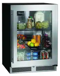
PLACING THE CABINET
To assure maximum performance, fresh air must
be allowed to circulate through the machinery
compartment. Do not place anything in front of the
cabinet that would obstruct air ow at these grilles. Do
not place the unit in an unventilated small room.
N OTICE
Cabinet should be leveled front to
back then side to side
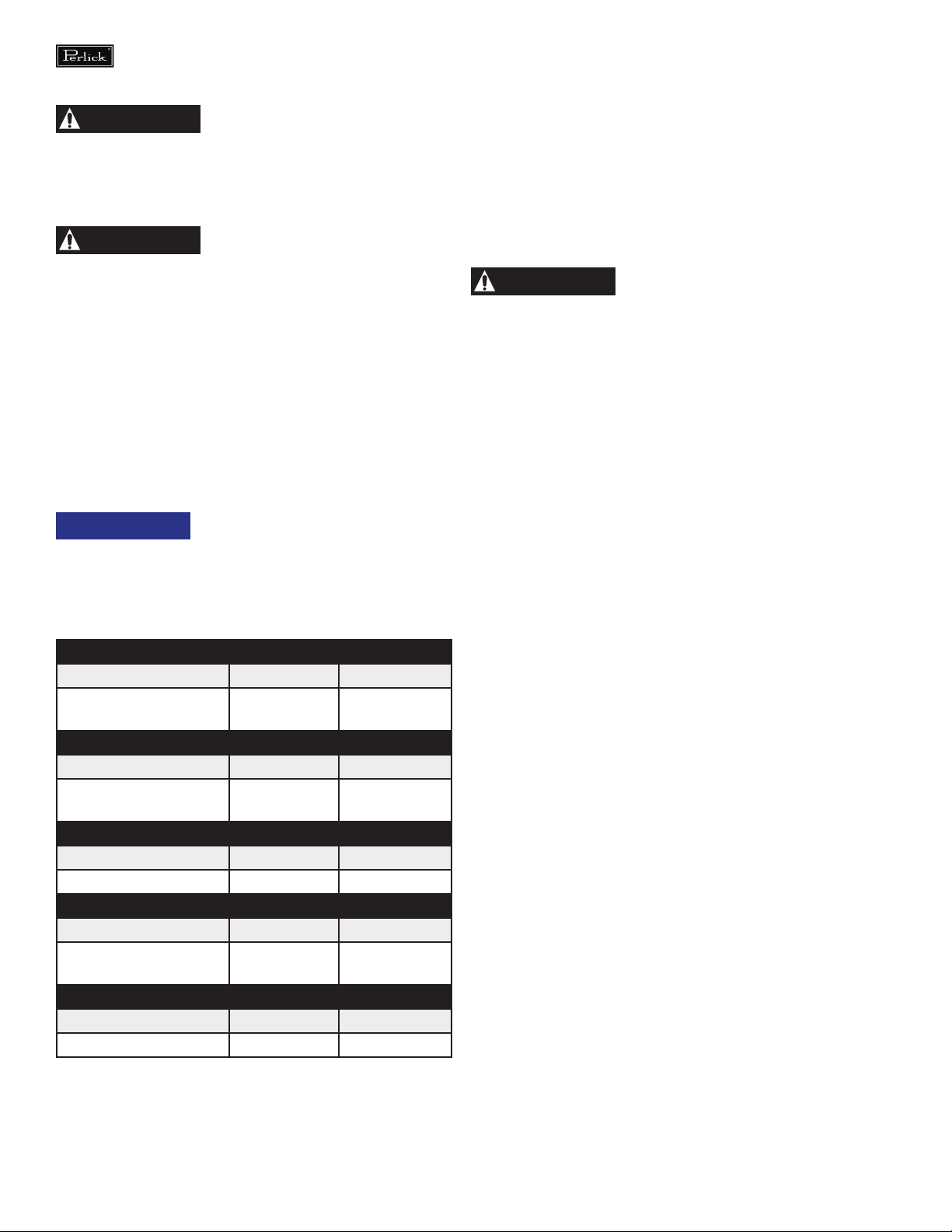
1). Make sure the space opening is correctly sized for
the unit. See chart below for nished rough opening
requirements:
HP15 15” Signature Series
Height Depth Width
34-3/8” minimum,
35-1/2” maximum
24” 15”
HP24 24” Signature Series
Height Depth Width
34-3/8” minimum,
35-1/2” maximum
24” 24”
HH24 Signature Shallow Depth
Height Depth Width
32-1/2” 18” 24”
HC24 24” C-Series
Height Depth Width
34-3/8” minimum,
35-1/2” maximum
24” 24”
HA24 24” ADA-Compliant Series
Height Depth Width
32-1/2” 24” 24”
NOTE: For a cabinet door to open properly, the door must open a
minimum of 90°. Use a minimum 3” ller in corner installations to
assure a full 90° opening. Allow 25” clearance in front of unit for full
door swing and shelf/drawer pull out for all units.
2). Check that the following are level and square:
• Front and interior opening
• Installation opening and oor surface
• Countertop bottom front edge
NOTE: The oor under the unit must be at the same level as the
surrounding nished oor.
CAUTION
To prevent possible damage to
the countertop, do not place
heavy objects on countertop directly over unit.
INSTALLING THE UNIT
1) Plug the unit into the 15 amp grounded electrical
outlet located within the installation opening. With
power applied to the unit, check that the lighting and
cooling functions operate properly. Turn o the power
to the wall outlet at the circuit breaker.
2) With all surfaces in the installation opening square
and level, refer to Figure 4 on page 7 and perform the
following steps to level the unit:
• At the front of the opening, measure from the oor to
the bottom of the front edge of the countertop.
• Measure from the oor surface to the top of the unit
at the rear corners.
• Adjust the unit legs so these two measurements are
equal. Using an adjustable wrench or pliers, turn legs
clockwise to lower the unit or counterclockwise to raise it.
NOTE: Legs should not extend more than 3/4” from the bottom
of the unit.
3) Slide the unit into position in the opening. Make sure
the rear leveling legs slide under the ant-tip brackets.
Push the unit into the opening until the bottom front
edge of the unit is ush with the surrounding cabinetry,
or until the rear legs are tight against the anti-tip
brackets.
4) Shim the front of the unit so the front face is ush
with the surrounding cabinetry. Adjust the front legs to
support the countertop at the shimmed height. Using
an adjustable wrench or pliers, turn the legs clockwise to
lower the unit or counterclockwise to raise it. Countertop
should be resting on top of the unit.
NOTE: Countertop should be resting evenly on entire top of the
unit. Shim if necessary to prevent damage to the countertop.
Loading ...
Loading ...
Loading ...