
Loading ...
Loading ...
Loading ...
10
Indoor Fan Speed Selections - AUTO/HIGH
Unit may be operated in HIGH HEAT, AUTO HEAT,
HIGH COOL or AUTO COOL.
In “AUTO”, the indoor fan will be in low speed for quieter
operation if the room temperature is within 1.8°F of the set
point, or in high speed if the room temperature is more
than 1.8°F away from the set point.
This feature allows the greatest control over the room
temperature while reducing the operating sound level.
Fan Only Setting - HIGH/LOW
The unit provides the option of selecting either HIGH or
LOW speed for Fan Only operation.
Fan Cycle Switch - “SmartFan”
Unique “SmartFan” allows unit to operate in fan continuous
in cooling operation and fan cycle in heating to provide
better guest comfort. This eliminates complaint of cold air
draft during heating operation.
This feature eliminates need of changing fan cycle switch
seasonally.
“SmartFan” settings are controlled by separate fan cycle/
continuous switches for heating and cooling modes.
Automatic Compressor Random Restart
In the event of a power failure all compressors attempting to
restart immediately when power is restored can result in a
power surge that can cause another power interruption.
The microprocessor in the Zoneline units have a random
restart logic system that prevents all units from starting at
the same time.
Rotary Compressor
Smoother operation for quiet, dependable service. GE has
used rotary compressors since 1961.
Compressor Restart Delay
Zonelines are designed to provide a minimum of three
minutes of compressor off time to allow refrigerant
pressures to equalize before restarting, to prevent damage to
compressor.
Zonelines are also designed to provide a minimum of three
minutes of compressor run time to prevent room occupant
disturbance due to short cycling air conditioner.
Freeze Sentinel
™
Detects low room temperature and turns on heater to help
protect against damage by freezing temperature in the room.
Heater automatically turns on at 41°F, warms indoor
thermistor temperature to 46°F, and shuts off.
Freeze Sentinel may be turned off by dip switch on auxiliary
control.
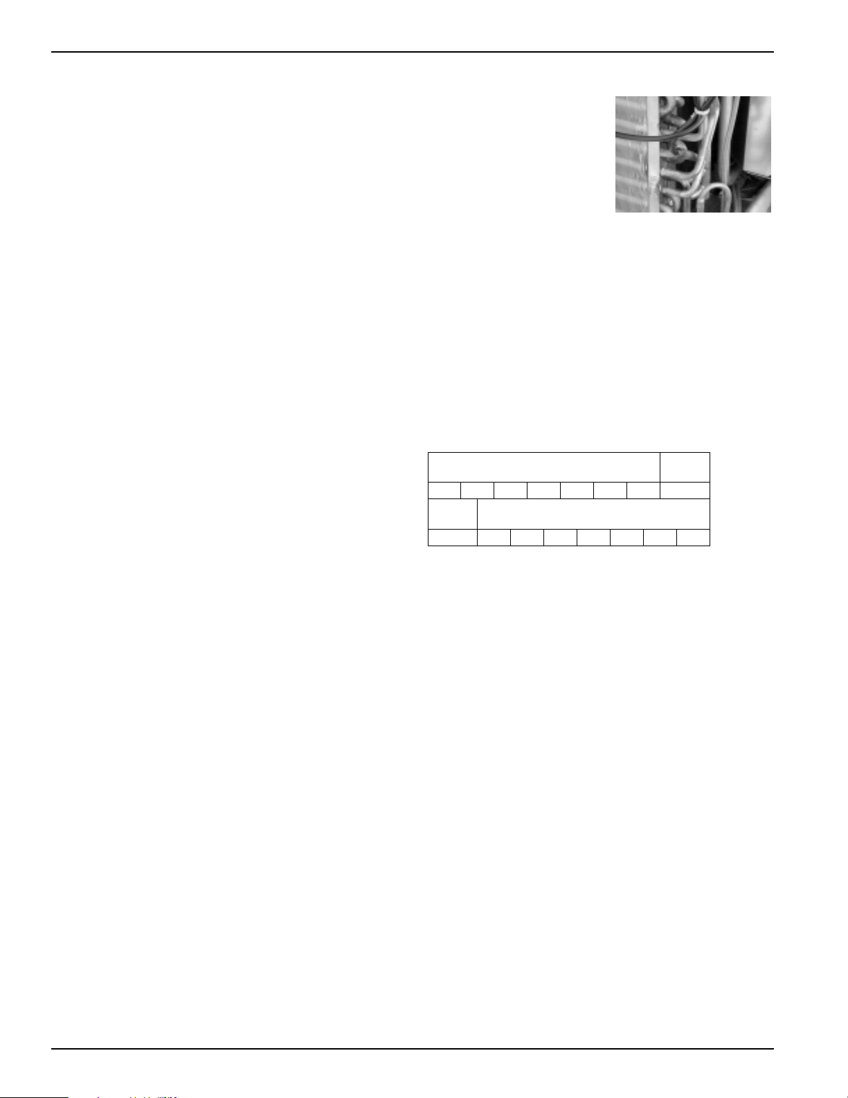
Indoor Coil Frost Control
Prevents indoor coil from
freezing and causing
complaints due to lack of
cooling. Frost can form on the
indoor coil when the unit is
operated in cooling when
outdoor temperatures are low.
The unit automatically shuts
the compressor off until the
indoor coil temperature warms
to the point where frosting will no longer occur.
Transfer Fan Interface
24 VAC terminals are provided to operate a relay to control
a fan mounted in a wall to move conditioned air into
another space. Transfer fans and their controlling relays are
field supplied.
Electronic Temperature Limiting
7 independent programmable heating temperature limits
and 7 independent programmable cooling temperature
limits. Wide selection of limits eliminates need to reset the
limits seasonally.
Limits are set by dip switches on auxiliary control panel.
Remote Control Capability with Wall Mounted
Thermostat
See pages 15 - 18
Central Desk Control Capability
See page 14
Energy Management System Interface With
Load Shedding Option
All units have a switch on the auxiliary control panel to allow
the indoor fan to continue operating if the unit is connected
to an Energy Management System that shuts off compressor
or heater operation. By allowing the indoor fan to run
when the heater or compressor is shut off by the Energy
Management System, the guest is less likely to realize the
operation of the unit has been altered. This helps to reduce
peak energy demand loads without disturbing the room
occupant.
Reversible Indoor Air Louvers
Allows air to be directed into room at 40 or 50 degree angles
to provide better air distribution.
Angle is changed by removing room front and screws
holding louver in place and rotating louver section 180°.
Heating Temperature Limits
Highest
Heat
65 70 72 74 76 78 80 85
Lowest
Cool
Cooling Temperature Limits
60 64 66 68 70 72 74 76
2020 Data Manual 2002 11/7/02 3:19 PM Page 10
Loading ...
Loading ...
Loading ...