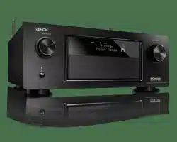

AV SURROUND RECEIVER
AVR-5805CI
OPERATING INSTRUCTIONS
2
2 SAFETY PRECAUTIONS
2 NOTE ON USE / OBSERVATIONS RELATIVES A L’UTILISATION
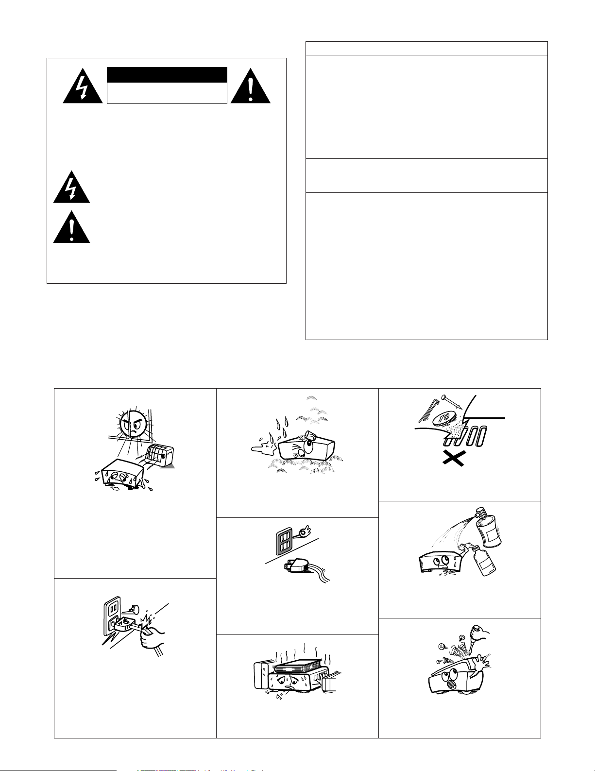
•Avoid high temperatures.
Allow for sufficient heat dispersion when
installed in a rack.
• Eviter des températures élevées
Tenir compte d’une dispersion de chaleur
suffisante lors de l’installation sur une
étagère.
• Handle the power cord carefully.
Hold the plug when unplugging the cord.
• Manipuler le cordon d’alimentation avec
précaution.
Tenir la prise lors du débranchement du
cordon.
• Keep the apparatus free from moisture,
water, and dust.
•Protéger l’appareil contre l’humidité, l’eau et
lapoussière.
• Unplug the power cord when not using the
apparatus for long periods of time.
•Débrancher le cordon d’alimentation lorsque
l’appareil n’est pas utilisé pendant de
longues périodes.
* (For apparatuses with ventilation holes)
• Do not obstruct the ventilation holes.
• Ne pas obstruer les trous d’aération.
• Do not let foreign objects into the apparatus.
• Ne pas laisser des objets étrangers dans l’appareil.
• Do not let insecticides, benzene, and thinner come
in contact with the apparatus.
•Ne pas mettre en contact des insecticides, du
benzène et un diluant avec l’appareil.
• Never disassemble or modify the apparatus
in any way.
• Ne jamais démonter ou modifier l’appareil
d’une manière ou d’une autre.
CAUTION
RISK OF ELECTRIC SHOCK
DO NOT OPEN
CAUTION: TO REDUCE THE RISK OF ELECTRIC SHOCK,
DO NOT REMOVE COVER (OR BACK). NO
USER-SERVICEABLE PARTS INSIDE. REFER
SERVICING TO QUALIFIED SERVICE
PERSONNEL.
The lightning flash with arrowhead symbol, within an
equilateral triangle, is intended to alert the user to the
presence of uninsulated “dangerous voltage” within the
product’s enclosure that may be of sufficient magnitude to
constitute a risk of electric shock to persons.
The exclamation point within an equilateral triangle is intended
to alert the user to the presence of important operating and
maintenance (servicing) instructions in the literature
accompanying the appliance.
WARNING: TO REDUCE THE RISK OF FIRE OR ELECTRIC
SHOCK, DO NOT EXPOSE THIS APPLIANCE
TO RAIN OR MOISTURE.
FCC INFORMATION (For US customers)
1. COMPLIANCE INFORMATION
Product Name: AV Surround Receiver
Model Number: AVR-5805CI
This product complies with Part 15 of the FCC Rules. Operation is subject to
the following two conditions: (1) this product may not cause harmful
interference, and (2) this product must accept any interference received,
including interference that may cause undesired operation.
Denon Electronics (USA), LLC
(a D & M Holdings Company)
100 Corporate Drive
Mahwah, NJ 07430-2041
Tel. (800) 497-8921
2. IMPORTANT NOTICE: DO NOT MODIFY THIS PRODUCT
This product, when installed as indicated in the instructions contained in this
manual, meets FCC requirements. Modification not expressly approved by
DENON may void your authority, granted by the FCC, to use the product.
3. NOTE
This product has been tested and found to comply with the limits for a Class
B digital device, pursuant to Part 15 of the FCC Rules. These limits are
designed to provide reasonable protection against harmful interference in a
residential installation.
This product generates, uses and can radiate radio frequency energy and, if
not installed and used in accordance with the instructions, may cause
harmful interference to radio communications. However, there is no
guarantee that interference will not occur in a particular installation. If this
product does cause harmful interference to radio or television reception,
which can be determined by turning the product OFF and ON, the user is
encouraged to try to correct the interference by one or more of the following
measures:
• Reorient or relocate the receiving antenna.
• Increase the separation between the equipment and receiver.
• Connect the product into an outlet on a circuit different from that to which
the receiver is connected.
• Consult the local retailer authorized to distribute this type of product or an
experienced radio/TV technician for help.
This Class B digital apparatus complies with Canadian ICES-003.
Cet appareil numérique de la classe B est conforme à la norme NMB-003 du
Canada.
3
SAFETY INSTRUCTIONS
1. Read Instructions – All the safety and operating instructions
should be read before the product is operated.
2. Retain Instructions – The safety and operating instructions
should be retained for future reference.
3. Heed Warnings – All warnings on the product and in the
operating instructions should be adhered to.
4. Follow Instructions – All operating and use instructions should
be followed.
5. Cleaning – Unplug this product from the wall outlet before
cleaning. Do not use liquid cleaners or aerosol cleaners.
6. Attachments – Do not use attachments not recommended by
the product manufacturer as they may cause hazards.
7. Water and Moisture – Do not use this product near water – for
example, near a bath tub, wash bowl, kitchen sink, or laundry
tub; in a wet basement; or near a swimming pool; and the like.
8. Accessories – Do not place this product on an unstable cart,
stand, tripod, bracket, or table. The product may fall, causing
serious injury to a child or adult, and serious damage to the
product. Use only with a cart, stand, tripod, bracket, or table
recommended by the manufacturer, or sold with the product.
Any mounting of the product should follow the manufacturer’s
instructions, and should use a
mounting accessory
recommended by the
manufacturer.
9. A product and cart
combination should be
moved with care. Quick
stops, excessive force,
and uneven surfaces may
cause the product and cart
combination to overturn.
10. Ventilation – Slots and openings in the cabinet are provided for
ventilation and to ensure reliable operation of the product and to
protect it from overheating, and these openings must not be
blocked or covered. The openings should never be blocked by
placing the product on a bed, sofa, rug, or other similar surface.
This product should not be placed in a built-in installation such
as a bookcase or rack unless proper ventilation is provided or
the manufacturer’s instructions have been adhered to.
11. Power Sources – This product should be operated only from the
type of power source indicated on the marking label. If you are
not sure of the type of power supply to your home, consult your
product dealer or local power company. For products intended
to operate from battery power, or other sources, refer to the
operating instructions.
12. Grounding or Polarization – This product may be equipped with
a polarized alternating-current line plug (a plug having one blade
wider than the other). This plug will fit into the power outlet
only one way. This is a safety feature. If you are unable to
insert the plug fully into the outlet, try reversing the plug. If the
plug should still fail to fit, contact your electrician to replace your
obsolete outlet. Do not defeat the safety purpose of the
polarized plug.
13. Power-Cord Protection – Power-supply cords should be routed
so that they are not likely to be walked on or pinched by items
placed upon or against them, paying particular attention to
cords at plugs, convenience receptacles, and the point where
they exit from the product.
15. Outdoor Antenna Grounding – If an outside antenna or cable
system is connected to the product, be sure the antenna or
cable system is grounded so as to provide some protection
against voltage surges and built-up static charges. Article 810
of the National Electrical Code, ANSI/NFPA 70, provides
information with regard to proper grounding of the mast and
supporting structure, grounding of the lead-in wire to an
antenna discharge unit, size of grounding conductors, location
of antenna-discharge unit, connection to grounding electrodes,
and requirements for the grounding electrode. See Figure A.
16. Lightning – For added protection for this product during a
lightning storm, or when it is left unattended and unused for
long periods of time, unplug it from the wall outlet and
disconnect the antenna or cable system. This will prevent
damage to the product due to lightning and power-line surges.
17. Power Lines – An outside antenna system should not be
located in the vicinity of overhead power lines or other electric
light or power circuits, or where it can fall into such power lines
or circuits. When installing an outside antenna system,
extreme care should be taken to keep from touching such
power lines or circuits as contact with them might be fatal.
18. Overloading – Do not overload wall outlets, extension cords, or
integral convenience receptacles as this can result in a risk of
fire or electric shock.
19. Object and Liquid Entry – Never push objects of any kind into
this product through openings as they may touch dangerous
voltage points or short-out parts that could result in a fire or
electric shock. Never spill liquid of any kind on the product.
20.
Servicing – Do not attempt to service this product yourself as
opening or removing covers may expose you to dangerous
voltage or other hazards. Refer all servicing to qualified
service personnel.
21.
Damage Requiring Service – Unplug this product from the
wall outlet and refer servicing to qualified service
personnel
under the following conditions:
a) When the power-supply cord or plug is damaged,
b) If liquid has been spilled, or objects have fallen into the
product,
c) If the product has been exposed to rain or water,
d) If the product does not operate normally by following the
operating instructions. Adjust only those controls that are
covered by the operating instructions as an improper
adjustment of other controls may result in damage and will
often require extensive work by a qualified technician to
restore the product to its normal operation,
e) If the product has been dropped or damaged in any way, and
f) When the product exhibits a distinct change in performance
– this indicates a need for service.
22. Replacement Parts – When replacement parts are required, be
sure the service technician has used replacement parts
specified by the manufacturer or have the same characteristics
as the original part. Unauthorized substitutions may result in
fire, electric shock, or other hazards.
23. Safety Check – Upon completion of any service or repairs to this
product, ask the service technician to perform safety checks to
determine that the product is in proper operating condition.
24. Wall or Ceiling Mounting – The product should be mounted to a
wall or ceiling only as recommended by the manufacturer.
25. Heat – The product should be situated away from heat sources
such as radiators, heat registers, stoves, or other products
(including amplifiers) that produce heat.

4
Getting Started
Thank you for choosing the DENON AVR-5805CI AV Surround Receiver. This remarkable component has been engineered to
provide superb surround sound listening with home theater sources such as DVD, as well as providing outstanding high fidelity
reproduction of your favorite music sources.
As this product is provided with an immense array of features, we recommend that before you begin hookup and operation that
you review the contents of this manual before proceeding.
(to be continued on page 6.)
Cable indications
..........................................................................27
The video conversion function
....................................................28
On screen display for component video outputs and
HDMI output
..................................................................................28
Connecting equipment with HDMI terminals
[To convert analog video signals to HDMI signals]
...................29
Connecting a TV tuner
.................................................................30
Connecting a DBS tuner
..............................................................30
Connecting the external inputs (EXT. IN) terminals
.................31
Connecting a video camera or video game
...............................31
Connecting a DVD recorder
.........................................................32
Connecting a VCR
.........................................................................33
Connecting a CD player
...............................................................33
Connecting a turntable
................................................................34
Connecting a CD recorder or MD recorder
................................34
Connecting a tape deck
...............................................................35
DENON LINK connection
.............................................................35
Connecting equipment with HDMI terminals
............................36
Connecting equipment with DVI-D terminals
...........................37
Connecting IEEE1394 devices
......................................................38
Connecting the antenna terminals
.............................................39
Connecting the XM terminal
.......................................................40
Connecting the CONTROL terminal
............................................40
Connecting the TRIGGER OUT terminals
...................................41
Connecting the MULTI ZONE terminals
ZONE2 connections .....................................................................41
Connecting the pre-out terminals
...............................................42
Connecting the power supply cord
............................................42
Contents
Getting Started
Accessories ...................................................................................7
Before using..................................................................................7
Cautions on installation............................................................7
Cautions on handling.................................................................8
Preparing the remote control unit.........................................8
Inserting the batteries...............................................................8
Operating range of the remote control unit.......................9
Part names and functions
Front panel .............................................................................10, 11
Display..........................................................................................12
Remote control unit .....................................................................13
Easy Setup and Operation
Easy to setup flow....................................................................14
Speaker system layout............................................................15
Speaker connections .........................................................16, 17
Connecting a DVD player and TV (Monitor)...............18, 19
Auto Setup / Room EQ ...........................................................20
Connecting a microphone ............................................................21
Turning on the power ...................................................................22
Starting Auto Setup......................................................................22
Extra Setup...................................................................................23
Preliminary measurements ....................................................23, 24
Speaker system measurement ....................................................24
Check of the measurement result ...............................................25
About the error message .............................................................26
Connecting Other Sources
Basic Operation
Playback
Operating the remote control unit ...............................................43
Playing the input source...............................................................44
Turning the sound off temporarily (MUTING)...............................45
Listening over headphones ..........................................................45
Switching the surround speakers ................................................45
Switching between HDMI and DVI-D monitor output .................45
Selection of resolution setting (SCALE) .......................................45
Combining the currently playing sound with the desired
image (VIDEO SELECT)................................................................45
Video on/off..................................................................................45
Checking the currently playing program source, etc. ..................46
Input mode ..........................................................................46 ~ 48
Room EQ function........................................................................48
Surround
Playing modes for different sources ............................................49
Playing audio sources (CDs and DVDs)
2 channel playback modes...........................................................50
THX Surround EX / Home THX Cinema mode
• Playing sources recorded in Dolby Surround in
the Home THX Cinema Surround mode ..................................51
•To play in the THX Surround EX / Home THX Cinema
Surround mode for sources recorded in Dolby Digital
or DTS .......................................................................................51 ~ 53
Dolby Digital mode and DTS Surround
(only with digital input) ...........................................................54, 55
Night mode ..................................................................................55
Dolby Pro Logic
II
x (Pro Logic
II
) mode.................................56, 57
DTS NEO:6 mode.........................................................................58
The Dolby Headphone..................................................................59
USER MODE function..................................................................59
DENON original surround modes
Surround modes and their features .............................................60
DSP surround simulation .......................................................61, 62
Tone control setting
• Adjusting the tone from the remote control unit...............62, 63
• Adjusting the tone from the main unit.....................................63
•Tone defeat mode ....................................................................63
Channel Level...............................................................................64
Fader function ..............................................................................65
Listening to the radio
Auto tuning...................................................................................65
Manual tuning ..............................................................................66
Preset memory ............................................................................66
Checking the preset stations .......................................................67
Recalling preset stations ..............................................................67
RDS (Radio Data System) ............................................................67
RDS search ..................................................................................68
PTY search ...................................................................................69
TP search ...............................................................................69, 70
RT (Radio Text) .............................................................................70
XM Satellite Radio
Checking the XM signal strength and Radio ID ...........................71
Channel selection.........................................................................72
Category search ...........................................................................72
Direct access of channels ............................................................73
5
2 System Setup Menu
page 140, 141
page 141, 142
page 142, 143
page 143 ~ 145
page 145, 146
page 146, 147
page 147, 148
page 104
page 105
page 106
page 106, 107
page 107
page 108
page 108 ~ 110
page 111, 112
page 112
page 112
page 113, 114
page 114
page 116
page 117
page 117
page 118, 119
page 120
page 120
page 121
page 122, 123
page 123
page 123,124
page 124, 125
page 20 ~ 26
page 149
page 150
page 150, 151
page 115
page 151, 152
page 135
page 136
page 137
page 126 ~ 128
page 129 ~ 133
page 134
page 138, 139

6
Getting Started
Advanced Operation
Remote control unit
Operating DENON audio components.........................................81
Setting the preset memory function............................................82
Operating a component stored in the preset memory ..........82, 83
Setting the learning function........................................................84
Using the system call function.....................................................84
• Registering ...............................................................................85
• Operating..................................................................................85
Setting the punch through function .............................................85
Setting the back light’s lighting time............................................85
Setting the brightness..................................................................85
Resetting the remote control unit................................................86
Multi zone music entertainment system...........................87
ZONE2 playback ..................................................................87 ~ 90
ZONE3 playback...........................................................................91
ZONE4 playback...........................................................................92
Outputting a program source to an amplifier, etc.,
in a ZONE2 room (ZONE2 SELECT mode) ..................................93
Outputting a program source to an amplifier, etc.,
in a ZONE3 or ZONE4 room (ZONE3, ZONE4 SELECT mode) ....93
Remote control unit operations during multi-source playback.....94
System setup for multi-zone........................................................95
Adjustment steps that need to be performed prior to
surround sound playback in ZONE2
•Test Tone ..................................................................................95
• Channel Level...........................................................................95
• Fader function ..........................................................................96
ZONE2 Surround ..........................................................................97
USER MODE function of ZONE2 ................................................97
ZONE2 tone control setting .........................................................98
Other function
Playing Super Audio CDs with an IEEE1394 cable ......................99
Multi-source recording / playback
• Playing one source while recording another
(REC OUT mode)....................................................................100
• Recording Dolby Digital and DTS multi channel sources.......100
• Dolby Headphone recording...................................................101
Last function memory ................................................................101
Initialization of the microprocessor ............................................101
Advanced Setup – Part 2
Speaker Setup
Setting the type of speakers..............................................140, 141
Setting the low frequency distribution...............................141, 142
Setting the Delay Time.......................................................142, 143
Setting the Channel Level ...............................................143 ~ 145
• Adjusting the test tone using the remote control unit...........145
Setting the Crossover Frequency ......................................145, 146
• Setting the crossover frequency individually for the
different channels...................................................................146
Selecting the Surround Speakers
for the different surround modes ......................................146, 147
Settings the THX Audio Setup
• Settings for using a THX Ultra2 compatible subwoofer ........147
• Surround Back Speaker Position Settings..............................148
Others Setup
Setting the Room EQ Setup ......................................................149
Setting the Direct Mode Setup ..................................................150
Setting the MIC Input Select .............................................150, 151
Check the parameter .........................................................151, 152
System setup items and default values................153 ~ 156
Troubleshooting ..............................................................157, 158
Additional information ...............................................159 ~ 173
Specifications...................................................................174, 175
Using the Network Audio Function
Internet radio function..................................................................74
Music server function ..................................................................74
System requirements ..........................................................74 ~ 76
Listening to Internet radio......................................................76, 77
Presetting (registering) Internet radio stations.............................77
Registering Internet radio stations in your favorites..............77, 78
Character search function (searching by first letter) ....................78
Updating the list of radio stations ................................................79
Playing music files stored on the computer
(music server).........................................................................79, 80
Operating the AVR-5805CI using a browser ................................80
Advanced Setup – Part 1
Navigating through the System Setup Menu................102
On screen display and front display .................................103
Audio Input Setup
Setting the Digital In Assignment ..............................................104
• Setting the DENON LINK .......................................................104
Setting the EXT. IN Setup ..........................................................105
Setting the Input Function Level................................................106
Setting the Function Rename ............................................106, 107
Setting the IEEE1394 Assignment.............................................107
Setting the IEEE1394 Auto Function .........................................108
Tuner Presets
•Auto Preset Memory..............................................................108
•Preset Skip .............................................................................109
•Preset Name ..................................................................109, 110
List of preset code
s ········································End of this manual
Video Setup
Setting the HDMI/DVI In Assignment................................111, 112
Setting the Component In Assignment .....................................112
Setting the Video Convert Mode ...............................................112
Setting the HDMI/Component Out Setup .........................113, 114
Setting the Audio Delay .............................................................114
Setting the On Screen Display (OSD) ........................................115
Advanced Playback
Setting the 2ch Direct/Stereo ....................................................116
Setting the Dolby Digital Setup..................................................117
Setting the Auto Surround Mode...............................................117
Setting the Manual EQ Setup ............................................118, 119
•Procedure for copying the “Flat” correction curve ................119
Zone Setup (ZONE2 = 5.1/7.1ch)
Setting the type of speakers for ZONE2....................................120
Setting the low frequency distribution for ZONE2.....................120
Setting the Delay Time for ZONE2.............................................121
Setting the Channel Level for ZONE2................................122, 123
Setting the Crossover Frequency for ZONE2 ............................123
Setting the Video Setup for ZONE2
•Video Convert Mode (ZONE2)................................................123
• Audio Delay (ZONE2)..............................................................124
Setting the ZONE3 and ZONE4 tone control
and channel level .................................................................124, 125
Option Setup
Setting the Channel Setup ..............................................126 ~ 128
Setting the Power Amplifier Assignment........................129 ~ 133
Setting the Volume Control........................................................134
Setting the Trigger Out...............................................................135
Setting the AC Outlet Assignment ............................................136
Memory backup and protecting the setting ..............................137
Setting the Network Setup ................................................138, 139
7
Getting Started
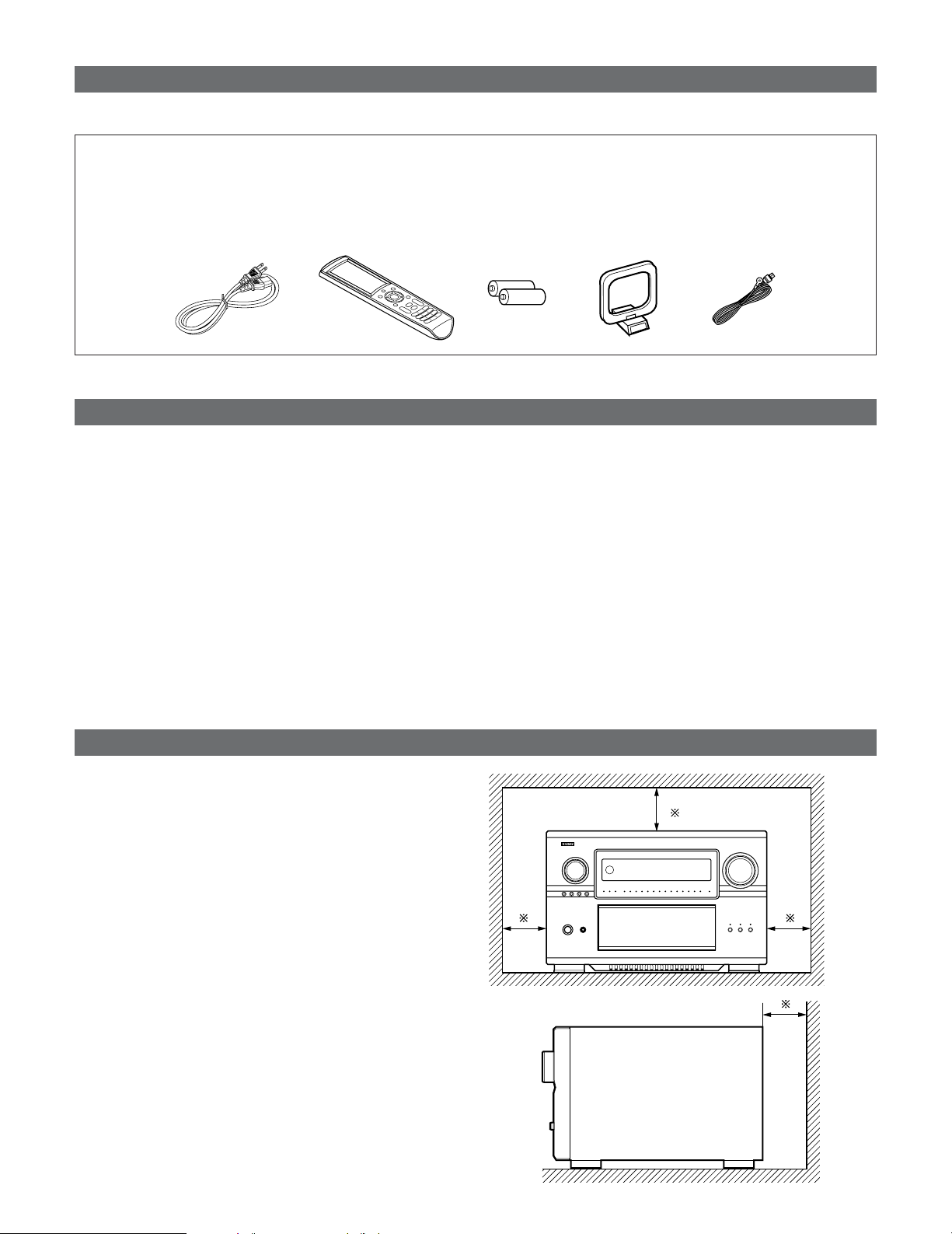
• Check that the following parts are included in addition to the main unit:
q Operating instructions ..................................................1
w Warranty (for North America model only).....................1
e Service station list.........................................................1
r Power supply cord ........................................................1
r
t
yui
t Remote control unit (RC-1036) .....................................1
y LR6/AA alkaline batteries..............................................2
u AM loop antenna ..........................................................1
i FM indoor antenna........................................................1
Before using
Pay attention to the following before using this unit:
• Moving the set
To prevent short circuits or damaged wires in the connection
cables, always unplug the power supply cord and disconnect
the connection cables between all other audio components
when moving the set.
• Before turning the Power operation button on
Check once again that all connections are proper and that
there are not problems with the connection cables. Always
set the power operation button to the standby position
before connecting and disconnecting connection cables.
Cautions on installation
Noise or disturbance of the picture may be generated if this
unit or any other electronic equipment using microprocessors
is used near a tuner or TV.
If this happens, take the following steps:
• Install this unit as far as possible from the tuner or TV.
• Set the antenna wires from the tuner or TV away from this
unit’s power supply cord and input/output connection cables.
• Noise or disturbance tends to occur particularly when using
indoor antennas or 300 Ω/ohms feeder wires. We
recommend using outdoor antennas and 75 Ω/ohms
coaxial cables.
Note:
For heat dispersal, do not install this unit in a confined
space such as a bookcase or similar enclosure.
Wall
Note
• Store these instructions in a safe place.
After reading, store these instructions along with the
warranty in a safe place.
• Note that the illustrations in these instructions may
differ from the actual set for explanation purposes.
Accessories
8
Getting Started
Preparing the remote control unit
• The included remote control unit (RC-1036) can be used to operate not only the AVR-5805CI but other remote control
compatible DENON components as well. In addition, the memory contains the control signals for other remote control units,
so it can be used to operate non-DENON remote control compatible products.
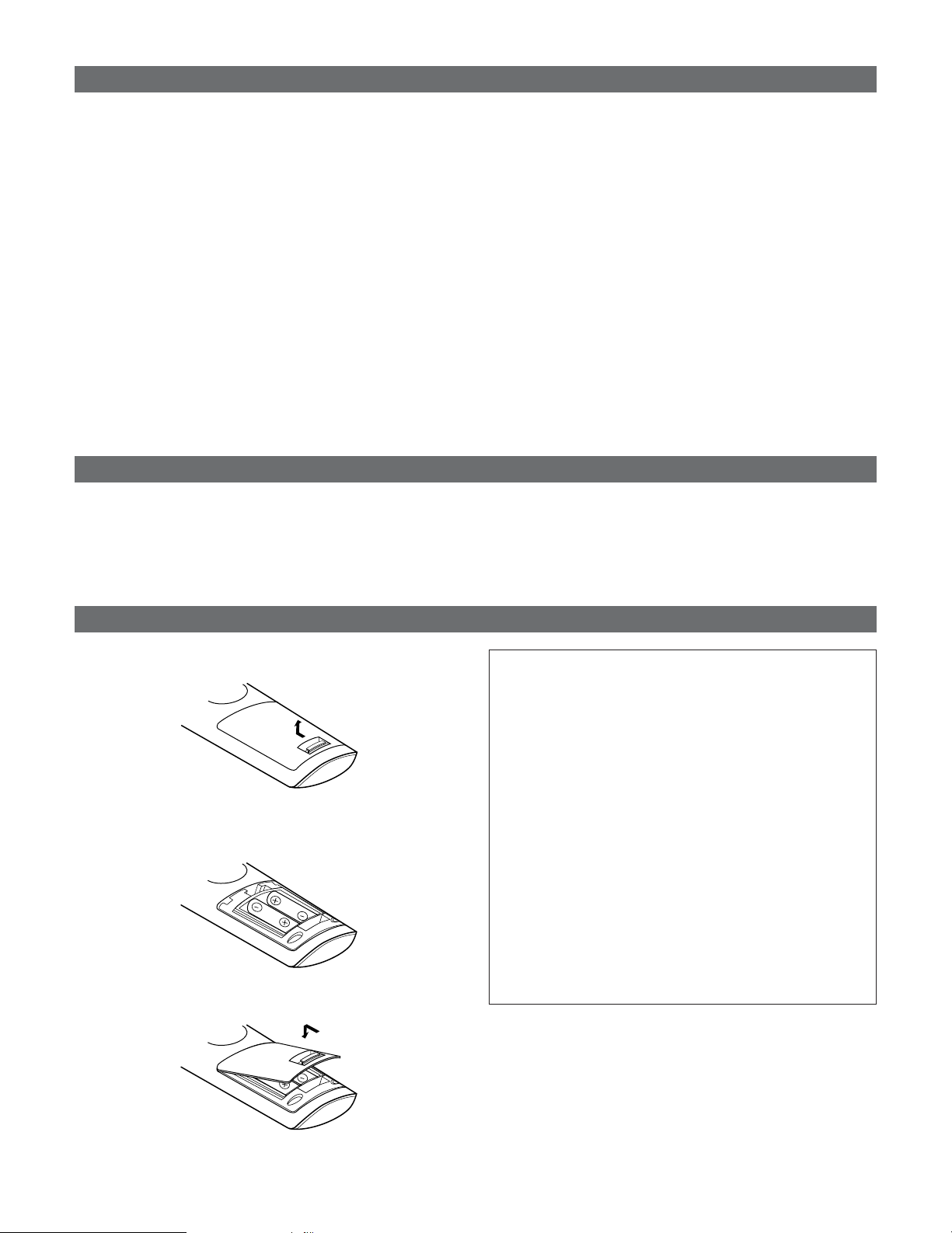
q Remove the remote control unit’s rear cover.
w Set two LR6/AA batteries in the battery compartment in
the indicated direction.
e Put the rear cover back on.
Notes on batteries:
• Replace the batteries with new ones if the set does not
operate even when the remote control unit is operated
nearby the set. (The included battery is only for verifying
operation.)
• When inserting the batteries, be sure to do so in the
proper direction, following the “
<
” and “
>
” marks in the
battery compartment.
•To prevent damage or leakage of battery fluid:
•Do not use a new battery together with an old one.
• Do not use two different types of batteries.
• Do not short-circuit, disassemble, heat or dispose of
batteries in flames.
• Remove the batteries from the remote if it will not be in
use for long periods.
•If the battery fluid should leak, carefully wipe the fluid off
the inside of the battery compartment and insert new
batteries.
•When replacing the batteries, have the new batteries
ready and insert them as quickly as possible.
Cautions on handling
• Switching the input function when input terminals are
not connected.
A clicking noise may be produced if the input function is
switched when nothing is connected to the input terminals.
If this happens, either turn down the MASTER VOLUME
control knob or connect components to the input terminals.
• Muting of PRE OUT terminals and SPEAKER terminals.
The PRE OUT terminals and SPEAKER terminals include a
muting circuit. Because of this, the output signals are
greatly reduced for several seconds after the power switch
is turned on or input function, surround mode or any other-
set-up is changed. If the volume is turned up during this
time, the output will be very high after the muting circuit
stops functioning. Always wait until the muting circuit turns
off before adjusting the volume.
Inserting the batteries
• Whenever the power operation button is in the
STANDBY state, the apparatus is still connected on AC
line voltage.
Please be sure to turn off the power switch or unplug
the cord when you leave home for, say, a vacation.
9
Getting Started
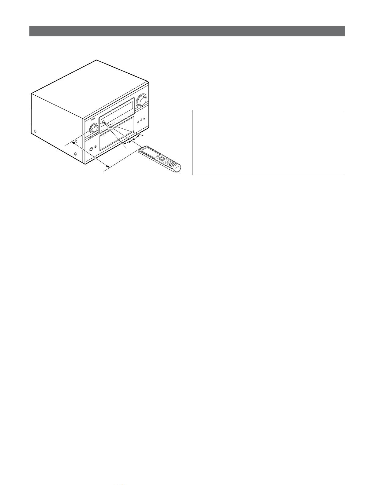
Operating range of the remote control unit
• Point the remote control unit at the remote sensor on the
main unit as shown on the diagram.
• The remote control unit can be used from a straight distance
of approximately 23 feet/7 meters from the main unit, but
this distance will be shorter if there are obstacles in the way
or if the remote control unit is not pointed directly at the
remote sensor.
• The remote control unit can be operated at a horizontal angle
of up to 30 degrees with respect to the remote sensor.
30°
30°
Approx. 23 feet/7 m
NOTE:
• It may be difficult to operate the remote control unit if the
remote sensor is exposed to direct sunlight or strong
artificial light.
• Do not press buttons on the main unit and remote control
unit simultaneously. Doing so may result in malfunction.
• Neon signs or other devices emitting pulse-type noise
nearby may result in malfunction, so keep the set as far
away from such devices as possible.
10
Getting Started
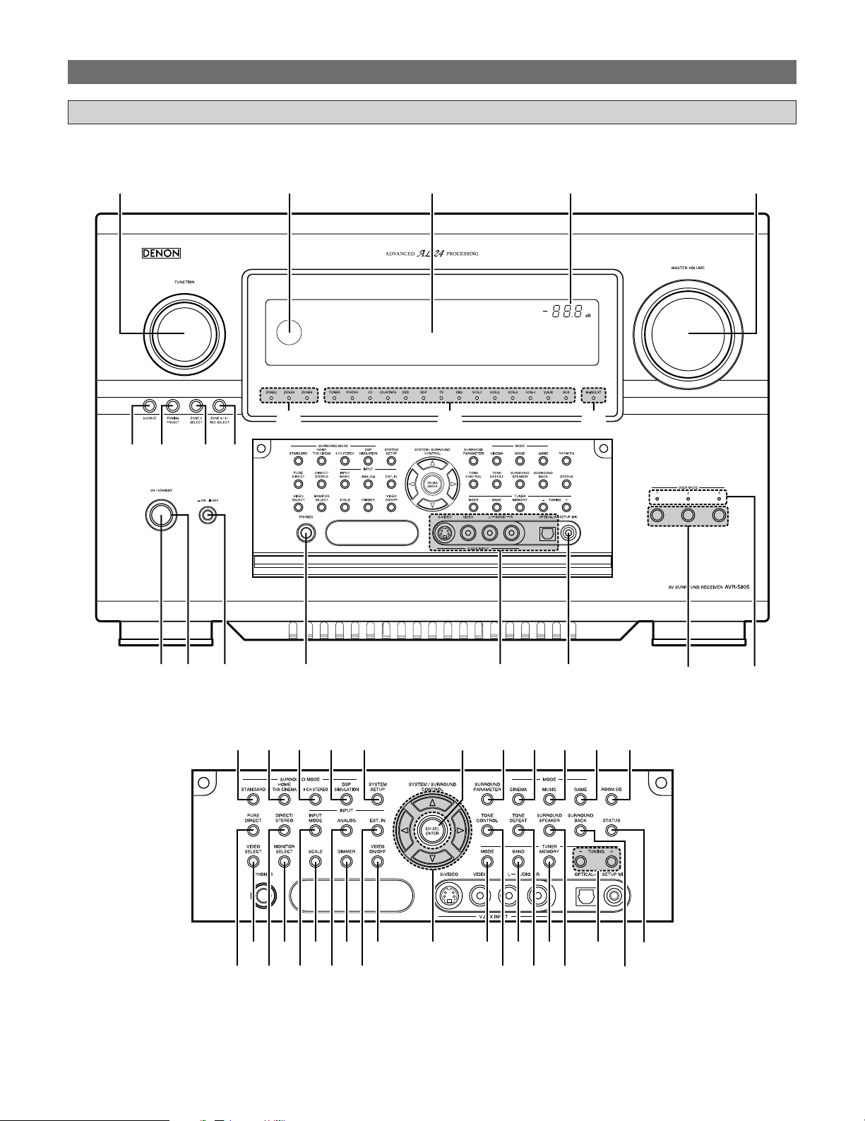
Part names and functions
• For details on the functions of these parts, refer to the pages given in parentheses ( ).
Front panel
!3 !2 !1 !0 o
q w e r t y
u i
!4 !5 !6 !7
!8
!9
@0
#7 #9 $1 $2#5
#4#2 #6 #8 $0
#3 $7$5$3 $9
%0
%1
$8$6$4
@2@1 @3 @4 @5 @8@7@6 @9 #0 #1

11
q Power ON/STANDBY button................................(22)
w Power indicator ........................................................(22)
e Power switch ....................................................(22, 101)
r Headphones jack (PHONES) .................................(45)
t V.AUX INPUT terminals .........................................(31)
y SETUP MIC jack........................................................(21)
u USER MODE buttons..............................................(60)
i USER MODE indicators..........................................(60)
o MASTER VOLUME control knob .........................(44)
!0 Master volume indicator........................................(44)
!1 Display ........................................................................(12)
!2 Remote control sensor.............................................(9)
!3 FUNCTION knob.......................................................(44)
!4 SOURCE button........................................................(44)
!5 TUNING PRESET button........................................(67)
!6 ZONE2 SELECT button...........................................(93)
!7 ZONE3/4/REC SELECT button .....................(93, 100)
!8 Multi Zone power indicators ................................(94)
!9 Input source indicators ..........................................(44)
@0 MultEQ XT indicator ...............................................(48)
@1 STANDARD button ..................................................(54)
@2 HOME THX CINEMA button .................................(44)
@3 9CH STEREO button................................................(62)
@4 DSP SIMULATION button......................................(62)
@5 SYSTEM SETUP button .........................................(22)
@6 CH SELECT/ENTER button..............................(22, 64)
@7 SURROUND PARAMETER button .......................(50)
@8 CINEMA button ........................................................(56)
@9 MUSIC button...........................................................(56)
#0 GAME button ............................................................(56)
#1 ROOM EQ button.....................................................(48)
#2 PURE DIRECT button ..............................................(50)
#3 VIDEO SELECT button............................................(46)
#4 DIRECT/STEREO button.........................................(50)
#5 MONITOR SELECT button.....................................(45)
#6 INPUT MODE button...............................................(47)
#7 SCALE button ...........................................................(45)
#8 ANALOG button.......................................................(47)
#9 DIMMER button........................................................(46)
$0 EXT.IN button............................................................(47)
$1 VIDEO ON/OFF button ...........................................(46)
$2 CURSOR buttons .....................................................(22)
$3 MODE button ............................................................(65)
$4 TONE CONTROL button.........................................(63)
$5 BAND button.............................................................(65)
$6 TONE DEFEAT button .............................................(63)
$7 MEMORY button ......................................................(66)
$8 SURROUND SPEAKER button..............................(45)
$9 TUNING buttons ......................................................(65)
%0 SURROUND BACK button.....................................(52)
%1 STATUS button.........................................................(46)
Getting Started
12
Getting Started
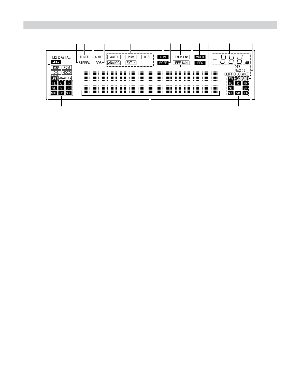
u yo!0!1!3!2!4!6!7!8 !5 i
e
r t
q
w
q Input signal indicator
The respective indicator will light corresponding to the
input signal.
w Input signal channel indicator
The channels included in the input source will light.
This lights when the digital signal is input.
e Information display
This displays the surround mode, function name or setting
value, etc.
r Output signal channel indicator
The audio channels that can be output light.
t Speaker indicator
This lights corresponding to the settings of the surround
speakers of the various surround modes.
y Decoder indicator
This lights when each decoder is operating.
u Master volume indicator
This displays the volume level.
The Setup item number is displayed in System Setup.
i IEEE1394 indicator
This lights during playback in a IEEE1394 connection.
o MULTI (zone) indicator
ZONE3 mode is selected in ZONE3/REC SELECT.
!0 Recording output source indicator
REC OUT mode is selected in ZONE3/REC SELECT.
!1 DENON LINK indicator
This lights during playback in a DENON LINK connection.
!2 V.OFF indicator
This lights when the operation of the video circuit has been
turned off.
!3 AL24 indicator
The AL24 indicator lights when the PURE DIRECT, DIRECT,
STEREO, MULTI CH PURE DIRECT , MULTI CH DIRECT,
MULTI CH IN mode is selected in the PCM input signal.
!4 Input mode indicator
This lights corresponding to the setting of the INPUT mode.
!5 RDS indicator
This lights when RDS broadcast has been received.
!6 AUTO indicator
This lights when the broadcast station is selected in the
AUTO tuning mode.
!7 TUNED indicator
This lights when an FM/AM broadcast has been received.
!8 STEREO indicator
This lights when an FM stereo broadcast has been received.
Display
13
Getting Started
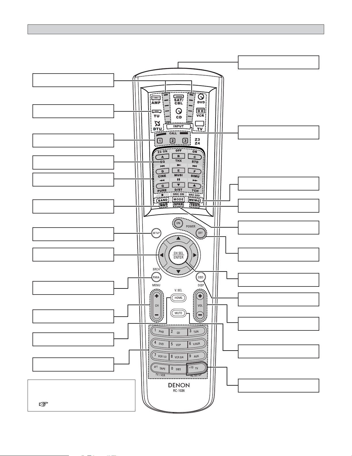
• For details on the functions of these parts, refer to the pages given in parentheses ( ).
NOTE:
• For instructions on setting the remote
control unit back light’s lighting time
( page 85).
Remote control unit
Surround mode/System
buttons ···································(50, 83)
MODE SELECTOR buttons
·······················································(81)
IR segment
·······················································(82)
ROOM EQ button
·······················································(48)
SYSTEM SETUP button
·······················································(22)
CURSOR buttons
·······················································(22)
SURROUND PARAMETER/SEARCH
button·······························(51, 67, 73)
Tuner system buttons
·······················································(65)
HOME/VIDEO SELECT button
·················································(46, 81)
Remote control signal transmitter
·························································(9)
INPUT MODE selector button
·······················································(47)
NIGHT button
·······················································(55)
SPEAKER button
·······················································(45)
TEST TONE button
···············································(95, 145)
Tuner system buttons
·······················································(65)
CH SELECT/ENTER button
·················································
(
22, 64
)
Power buttons
·······················································(22)
Master volume control buttons
·······················································(44)
ON SCREEN button
·······················································(46)
FUNCTION/NUMBER
buttons ···································(44, 82)
MUTE button
·······················································(45)
USER MODE/SYSTEM
CALL buttons ·························(60, 84)
RC SETUP button
·······················································(82)
Easy Setup and Operation
14
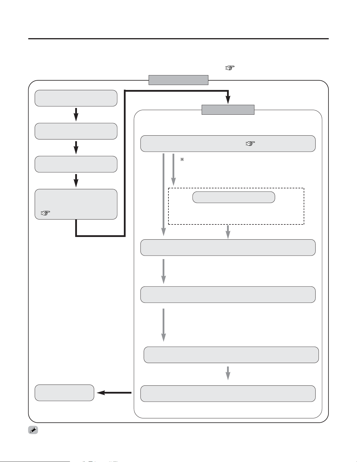
Placing the speakers.
Connecting the speakers.
Connect the DVD player to the
AVR-5805CI.
Connect the AVR-5805CI’s
monitor output terminal to
the TV’s video input terminal
( page 19).
Connecting a microphone ( page 21).
Perform the preliminary measurements.
The measurement of the speakers in the main listening position.
Check of the measurement result.
1) Measuring the background noise (noise in the room).
2) Determining whether or not speakers are connected.
3) Checking the polarities of the speakers.
1) Speaker Configuration
2) Delay Time (speaker distance)
3) Channel Level
4) Crossover Frequency
5) Room EQ
Easy to setup flow
Auto setup flow
Store the measurement result in the memory.
• This section contains the basic steps necessary to configure the AVR-5805CI according to your listening room environment and
the source equipment and loudspeakers you are using.
• For optimum performance, we recommend using the Auto Setup function.
• If you wish, you can set the various settings manually without using Auto Setup ( page 140 ~ 148).
Perform the auto setup procedure, following the
instructions displayed on the TV’s screen.
Play a DVD.
• Do not plug in the power supply cord until all connections have been completed.
By default, the speaker system setting is set
to 9.1 channels.
Please set under “Extra Setup”, only when
you want to change this arrangement.
Extra Setup
1) Channel Setup
2) Power Amplifier Assignment
The measurement of the speakers
in the 2nd to 8th listening position.
15
Easy Setup and Operation
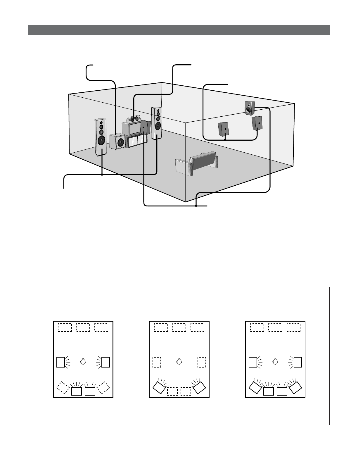
2 Basic system layout (For a THX Ultra2 system)
• The following is an example of the basic layout for a system consisting of eight speaker systems and a television monitor:
Subwoofer Center speaker system
Surround speaker systems
Surround back speaker systems
Front speaker systems
Set these at the sides of the TV or screen
with their front surfaces as flush with the
front of the screen as possible.
Two surround back speakers are required to use the THX Ultra2 Cinema,THX Music mode and THX Games mode.
Set the surround back speakers so that the distance to the listening position is the same for both the left and right speakers. It is
also recommended that the deviations of the distance from the listening position to L and R channel speakers (front left (FL) and
front right (FR), surround left (SL) and surround right (SR), surround back left (SBL) and surround back right (SBR)) is less than 2
ft (60 cm).
With the AVR-5805CI it is also possible to use the surround speaker selector function to choose the best layout for a variety of
sources and surround modes.
Speaker system layout
2 Surround speaker selector function
This function makes it possible to achieve the optimum sound fields for different sources by switching between two
systems of surround speakers (A and B). The settings of the different speakers (A only, B only or A+B) are stored in the
memory for the different surround modes, so they are set automatically when the surround mode is selected.
AA
BB
AA
BB
SB SB SB SB
BB
SB SB
AA
Using A only
(Multi surround speaker system)
Using B only
(Single surround speaker system)
(SB: Surround Back Speakers)
Using A and B
16
Easy Setup and Operation
Speaker connections
• Connect the speaker terminals with the speakers making
sure that like polarities are matched (
<
with
<
,
>
with
>
).
Mismatching of polarities will result in weak central sound,
unclear orientation of the various instruments, and the
sense of direction of the stereo being impaired.
NOTE:
• NEVER touch the speaker terminals when the power
is on. Doing so could result in electric shocks.
• When making connections, take care that none of the
individual conductors of the speaker cable come in
contact with adjacent terminals, with other speaker
cable conductors, or with the rear panel and screws.
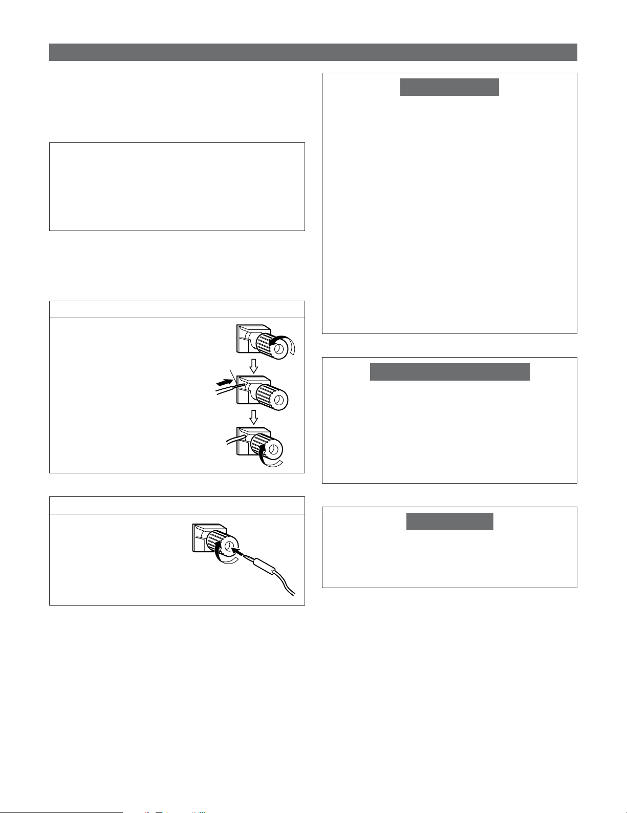
Connecting the speaker cables
1. Loosen by turning
counterclockwise.
2. Insert the cable.
3. Tighten by turning clockwise.
Either tightly twist or terminate the core wires.
Connecting banana plugs
Turn clockwise to tighten, then
insert the banana plug.
Protector circuit
This unit is equipped with a high-speed protection circuit.
The purpose of this circuit is to protect the speakers under
circumstances such as when the output of the power
amplifier is inadvertently short-circuited and a large current
flows, when the temperature surrounding the unit
becomes unusually high, or when the unit is used at high
output over a long period which results in an extreme
temperature rise.
When the protection circuit is activated, the speaker output
is cut off and the power supply indicator flashes. Should
this occur, please follow these steps: be sure to switch off
the power of this unit, check whether there are any faults
with the wiring of the speaker cables or input cables, and
wait for the unit to cool down if it is very hot. Improve the
ventilation condition around the unit and switch the power
back on.
If the protection circuit is activated again even though there
are no problems with the wiring or the ventilation around
the unit, switch off the power and contact a DENON
service center.
Note on speaker impedance
The protector circuit may be activated if the set is played for
long periods of time at high volumes when speakers with
an impedance lower than the specified impedance (for
example speakers with an impedance of lower than 4
Ω/ohms) are connected. If the protector circuit is activated,
the speaker output is cut off. Turn off the set’s power, wait
for the set to cool down, improve the ventilation around the
set, then turn the power back on.
2
Speaker Impedance
• Speakers with an impedance of from 6 to 16 Ω/ohms can
be connected.
Cooling fan
The AVR-5805CI is equipped with a cooling fan to prevent
the temperature inside the set from rising. The fan is
activated under certain usage conditions. It is temperature
sensitive, to minimize or prevent audible fan noise.
17
Easy Setup and Operation
2 Connections
• By default, the speaker system setting is set to 9.1 channels.
• The AVR-5805CI can be configured for 10 speaker playback using two pairs of surround speakers (A+B) and one pair of
surround back speakers as shown below.
• The output of each power amplifier can be assigned to any desired channel to best suit the application.
For details, refer to “Setting the Channel Setup” and “Setting the Power Amplifier Assignment” ( page 129 ~ 133).
• When making connections, also refer to the operating instructions of the other components.
>< <>
><
><
>< <>
<>
>< <>
IN
(
L
)
(
R
)
(
R
) (
L
)
(
L
)
(
R
) (
L
)
(
R
)
Connection
terminal for
subwoofer with
built-in amplifier
(subwoofer), etc.
Surround
left speaker
(A)
Subwoofer
Front
right speaker
• Precautions when connecting speakers
If a speaker is placed near a TV or video monitor, the colors on the screen may be disturbed by the speaker’s magnetism. If
this should happen, move the speaker away to a position where it does not have this effect.
Surround back
left speaker
Front
left speaker
Center
speaker
Surround back
right speaker
Surround
right speaker
(A)
Example: 9.1 channel connections
Surround
left speaker
(B)
Surround
right speaker
(B)
NOTE:
• Route the connection cables, etc., in such a way that they do not obstruct the ventilation holes.
• When using only one surround back speaker, connect it to left channel (L5).
18
Easy Setup and Operation
Connecting a DVD player and TV (Monitor)
DVD player
S VIDEO
OUT
COAXIAL
OUT
R
L
AUDIO OUT
VIDEO
OUT
COMPONENT VIDEO OUT
Y
P
B
PR
HDMI
OUT
DVI-D
OUT
R
L
R
L
H
J
I
A
C
M
L
•To connect the video output from the DVD player to the AVR-5805CI, you only need to choose one connection type. Component
video connection offers the best quality (and is required for progressive DVD playback), followed by S-Video, while composite
video offers the lowest picture quality of the three connection types. For more information about the video up conversion
function ( page 28).
• The AVR-5805CI is equipped with HDMI terminals, so it can be connected to a DVD player or TV (monitor) using an HDMI cable.
To connect it to a DVD player using a DVI-D cable ( page 37).
• The AVR-5805CI is equipped with a BNC terminal, so a DVD player or monitor can be connected using a BNC cable.
If you choose to use the BNC connection, it needs to be assigned. For more information about Component Input Assignment
( page 112).
•To connect the digital audio output from the DVD player, you can choose from either the coaxial or optical connections. If you choose
to use the optical connection, it needs to be assigned. For more information about Digital Input Assignment ( page 104).
• The AVR-5805CI is equipped with another set of input terminals for a non-DVD Video Disc Player (such as laser disc, VCD/SVCD,
or future high definition disc player). The above connection guidelines for DVD also apply to the VDP input.
Audio signal flow is shown with white arrows, video signal flow is shown with gray arrows.
19
Easy Setup and Operation
TV (Monitor)
S VIDEO
IN
VIDEO
IN
COMPONENT VIDEO IN
Y
P
B
PR
HDMI
IN
DVI-D
IN
COMPONENT VIDEO OUT
Y
PB
PR
H
J
I
M
L
K
or
• For best picture quality (especially with progressive DVD and other high definition sources) choose the component video or
HDMI connection to your monitor or TV. S-Video and composite video outputs are also provided if your TV does not have
component video inputs.
NOTE:
• The component video input and/or output terminals may be labeled differently on some TVs, monitors or video
components (Y, P
B, P
R; Y, CB, CR; Y, B-Y, R-Y). Check the operating instructions for other components for further
information.
• The COMPONENT MONITOR OUT-1 and the COMPONENT MONITOR OUT-2 can be used simultaneously. Connect with
a BNC cable when using the COMPONENT MONITOR OUT-1 terminal, a component video cable when using the
COMPONENT MONITOR OUT-2 terminal.
•The HDMI and DVI-D monitor output terminals on the AVR-5805CI can only be used one at a time, not simultaneously.
• Audio signals are only output from the HDMI monitor out connector when audio signals are input to the HDMI input
connector.
• When connecting the AVR-5805CI and DVD player using an HDMI cable, also connect the AVR-5805CI and monitor or TV
using an HDMI cable ( page 36).
20
Easy Setup and Operation
The Auto Setup and Room EQ function of this unit performs an
analysis of the speaker system and measures the acoustic
characteristics of your room to permit an appropriate automatic
setting.
The AVR-5805CI’s Audyssey MultEQ XT function has the
feature that it provides the optimum listening environment at
all listening positions in the home theater, where there are
often multiple listeners viewing programs together. To achieve
this, it is first necessary to use a microphone to measure test
tones generated from the different speakers at the various
listening positions. All this measured data is analyzed with a
unique method to comprehensively improve acoustic
characteristics in the listening area. For optimum
effectiveness, measurements should be performed at six or
more points. Move the microphone successively within the
listening area surrounded by the speakers as shown on the
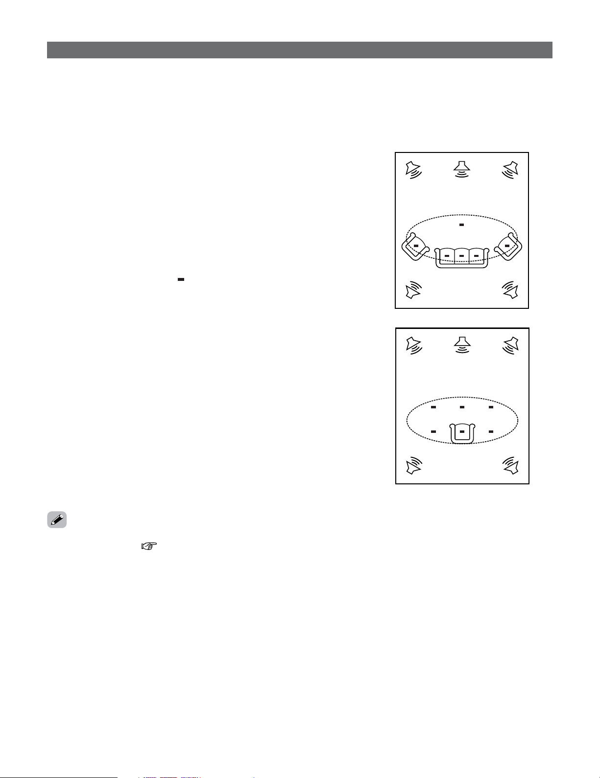
diagram below to measure the test tones. When listening to
music or viewing movies with the whole family, move the
microphone successively to the different positions in which
the members of the family sit (“ ” on the diagram indicates
the points of installation) and measure repeatedly (Example
q). Even if the number of people using the home theater is
small, taking multiple measurements at or near the listening
positions makes it possible to correct the sound more
effectively (Example w).
The AVR-5805CI’s Room EQ function offers three correction
curves: “Audyssey”, “Front” and “Flat”. These can be
selected after performing the auto setup procedure. Details of
the different correction curves are described below.
• Audyssey:
This adjusts the frequency response of all speakers to
correct the effects of room acoustics.
• Front:
This adjusts the characteristics of each speaker to the
characteristics of the front speakers.
• Flat:
Makes the frequency response for all the speakers flat.
This is suitable for multi-channel music reproduction, from
discrete music sources such as Dolby Digital 5.1, DTS, DVD-
Audio and Super Audio CD.
Example: w
*
M
Example: q
*
M
Auto Setup / Room EQ
2 About the main listening position (*M)
• The main listening position is the point where a listener
sits most often or the listening position when only one
person is listening. Measurements on the AVR-5805CI
start from this point. Correction for the speaker distance
(“Delay Time”) is set based on this point.
•To make the Speaker system settings without using the
Auto Setup function ( page 140 ~ 148).
21
Easy Setup and Operation
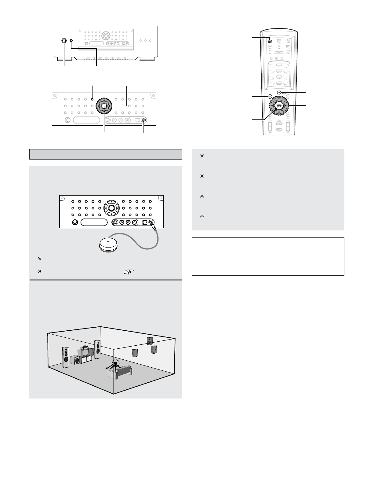
Connecting a microphone
1
Connect the optional microphone for Auto
Setup to the
SETUP MIC jack on the front
panel of the unit.
2
Mount the auto setup microphone onto a
camera tripod, etc., and place it at ear height
at the main listening position in the listening
room with the sound receptor facing the
ceiling.
Microphone
NOTE:
• Do not disconnect the microphone until the settings are
completed.
• Do not change the connection of speakers or the
subwoofer’s volume after performing these measurements.
ON/STANDBY
POWER
AMP
ON
SYSTEM SETUP
CURSOR
ENTER
When placing the microphone, adjust the height so
that the microphone’s sound receptor is at the height
of the ears of the listener.
Be sure that at the beginning, the measurement is
started with the microphone set up at the main
listening position.
It is not possible to measure properly if there are any
obstacles between the speakers and microphone.
Check that there are no obstacles.
Please do not stand between or near the speakers and
the microphone during the measurements.
The optional standard microphone is DENON DM-S305
sold separately.
When using other microphone ( page 150, 151).
SYSTEM SETUP
SETUP MIC
ENTER
CURSOR
22
Easy Setup and Operation
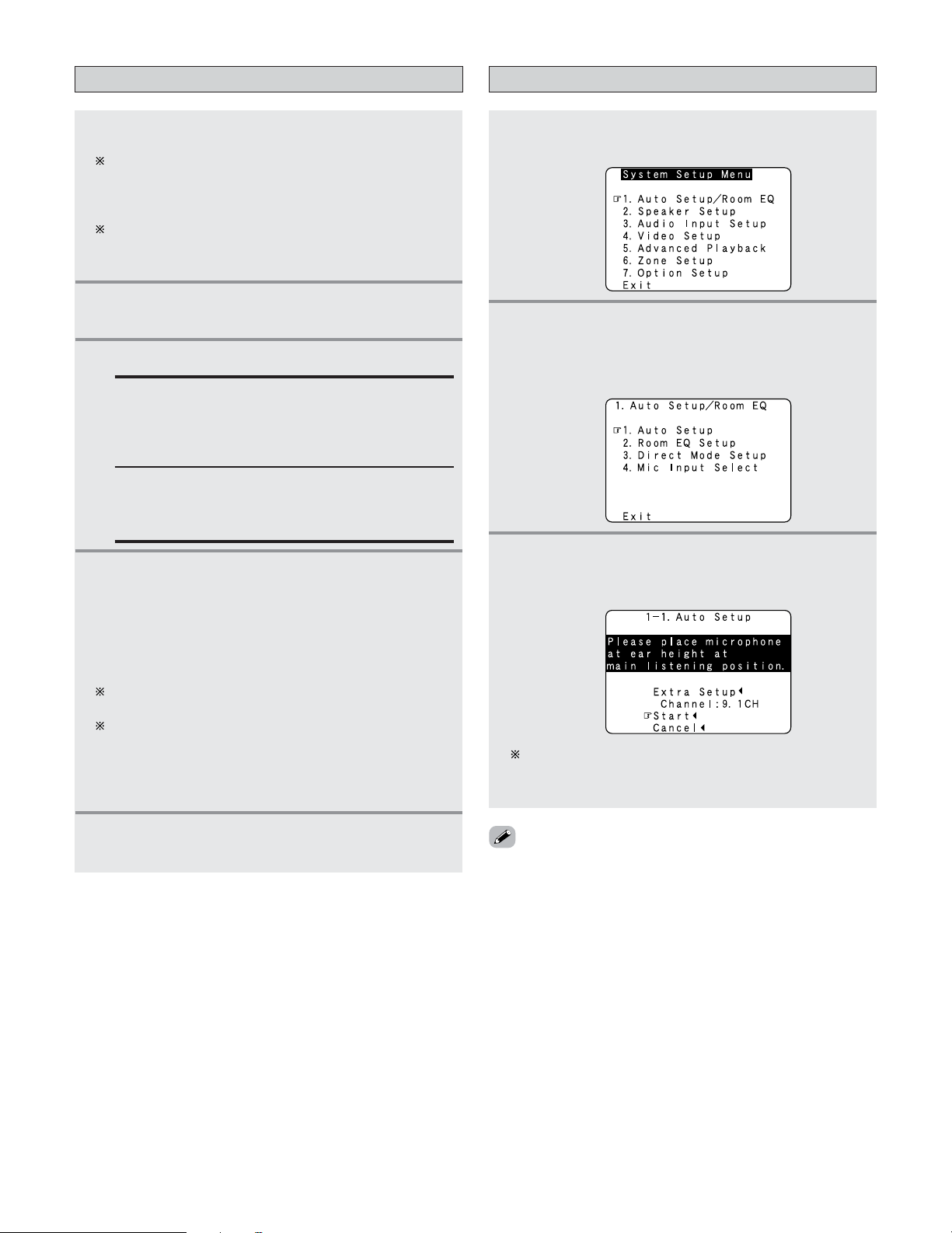
Starting Auto Setup
2
Press the CURSOR
DD
or
HH
button to select
“Auto Setup / Room EQ”, then press the
ENTER button.
• The “Auto Setup / Room EQ” menu appears.
1
Press the SYSTEM SETUP button.
• The “System Setup Menu” appears.
4
Press the ON/STANDBY switch on the main
unit or
ON button on the remote control unit.
• When pressed, the power turns on and the display
lights.
• When pressed again, the power turns off, the
standby mode is set and the display turns off.
The sound is muted for several seconds, after which
the unit operates normally.
Whenever the ON/STANDBY button is in the standby
state, the apparatus is still connected to the AC line
voltage. Please be sure to turn off the POWER switch or
unplug the cord when you leave home for, say, a
vacation.
5
Press the AMP button to select “AMP” (only
when operating with the remote control unit).
3
Press the CURSOR
DD
or
HH
button to select
“Auto Setup”, then press the
ENTER button.
• The “Auto Setup” screen appears.
The message “Connect Microphone” is displayed if no
microphone is connected. If so, connect the auto setup
microphone.
3
Press the POWER switch.
£ OFF:
The power turns off and indicator is off.
In this position, the power cannot be turned on and
off from the remote control unit.
¢ ON:
The power turns on and the power indicator lights.
Set the POWER switch to this position to turn the
power on and off from the included remote control
unit.
1
Turn on your subwoofer.
Set the volume to halfway and set the crossover
frequency to the maximum or Low pass filter off if your
subwoofer can adjust the output volume and the
crossover frequency.
Some subwoofers have a standby mode. Be sure to
turn this function off before performing the Auto Setup
procedure.
2
Turn on your TV (monitor).
Turning on the power
• If no operation is performed for approximately 3 minutes
during the auto setup procedure, the screensaver is
launched. The screensaver is canceled if any one of the
CURSOR, ENTER or SYSTEM SETUP button is pressed.
23
Easy Setup and Operation
4
If the check ends, press the ENTER button
again.
[ Second screen ]
3
Check the results of the speaker detection,
then press the
ENTER button.
• Switch to the second screen.
The screen shown at the below appears once the
preliminary measurements are completed.
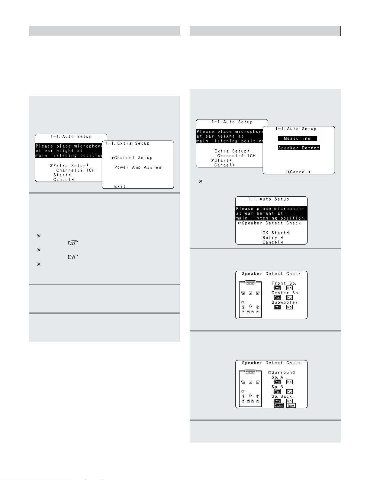
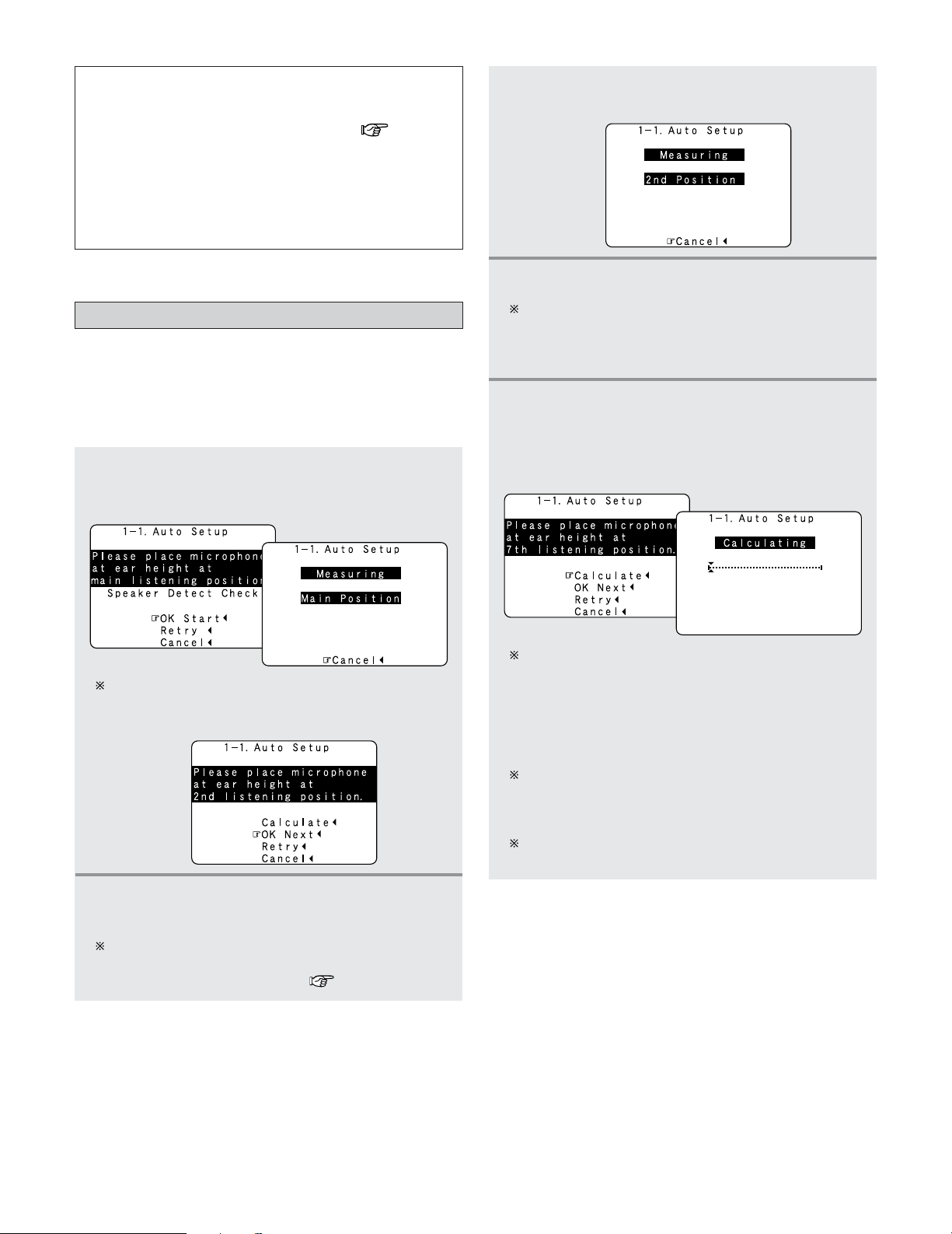
Preliminary measurements
• This procedure is used to automatically determine the
background noise, whether or not speakers are connected,
and the polarities of the connected speakers.
•To avoid affecting the measurements, turn off the air-
conditioner or any other device that makes noise and take
the measurements with the room as quiet as possible.
1
Press the CURSOR
DD
or
HH
button to select
“Start”, then press the
CURSOR
FF
button.
• Start the preliminary measurements.
2
Press the ENTER button.
• Switch to the “Speaker Detect Check” screen.
[ First screen ]
3
4
Once the settings are completed, press the
ENTER button at the each setting screen.
• The “Extra Setup” screen reappears.
Press the CURSOR
DD
or
HH
button to select
“Exit”, then press the
ENTER button.
• Return to the “Auto Setup” screen.
1
2
Press the CURSOR
DD
or
HH
button to select
“Extra Setup”, then press the
CURSOR
FF
button.
•Switch to the “Extra Setup” screen.
Extra Setup
• The AVR-5805CI has ten available amplifier channels, some
of which can be assigned for powering speakers in ZONE2,
ZONE3 and ZONE4 depending on the speaker system
complement in the main room. If this functionality is not
needed, skip this “Extra Setup” procedure and proceed to
“Preliminary Measurements”.
• By default, the speaker system setting is set to 9.1 channels.
Press the CURSOR
DD
or
HH
button to choose the
setting you want to change, then press the
ENTER button.
•Switch to the setting screen.
For instructions on making the “Channel Setup”
settings ( page 126 ~128).
For instructions on making the “Power Amp Assign”
settings ( page 129 ~ 133).
The speakers measured with this Auto Setup
procedure are based on the setting of these “Channel
Setup” and “Power Amp Assign” functions.
24
Easy Setup and Operation
4
Perform step 2, 3 repeatedly.
The more measurement points, the better the
resulting room correction effect. We recommend a
minimum of 6 measurement points – 8 measurement
points provides the best room correction effect.
5
After measuring at the number of points
according to your listening environment, press
the
CURSOR
DD
or
HH
button to select
“Calculate”, then press the
CURSOR
FF
button.
• The speaker system is analyzed.
The amount of time required for the analysis depends
on the number of speakers and the number of
measuring points. The greater the number of speakers
and measuring points, the longer the time required. For
example, for ten speaker systems and 6 measuring
points, the calculations require approximately 6
minutes.
Measurements can be ended when there are 5 or less
measurement locations; however, to obtain better
results, measurements at 6 or more locations is
recommended.
Once the calculations are completed, a screen for
confirming the results of the measurements appears.
Speaker system measurement
•With these measurements, the “Speaker Configuration”,
“Delay Time”, “Channel Level”, “Crossover Frequency” and
“Room EQ” are analyzed automatically. The main listening
position is measured first, so leave the microphone where it
is.
1
Press the CURSOR
DD
or
HH
button to select “OK
Start”, then press the
CURSOR
FF
button.
• Measurements for the first point start.
The screen shown at the below appears once the
measurements for the main listening position are
completed.
2
Next the measurements for the second point
will be taken.
Place the microphone at the second listening position.
For instructions on the position in which the
microphone should be placed ( page 20).
NOTE:
• If the results are not as expected or if an error message is
displayed, select “Retry” and perform the measurements
again. (For details on the error messages ( page 26).)
If the results of remeasurement are still not as expected
or if an error message is displayed, turn off the power
switch and check the speaker connections. Then start the
measurements again from the beginning.
• Measurement is cancelled when MASTER VOLUME is
operated while the Auto Setup is performed.
3
Press the CURSOR
FF
button.
• Measurements for the second point start.
25
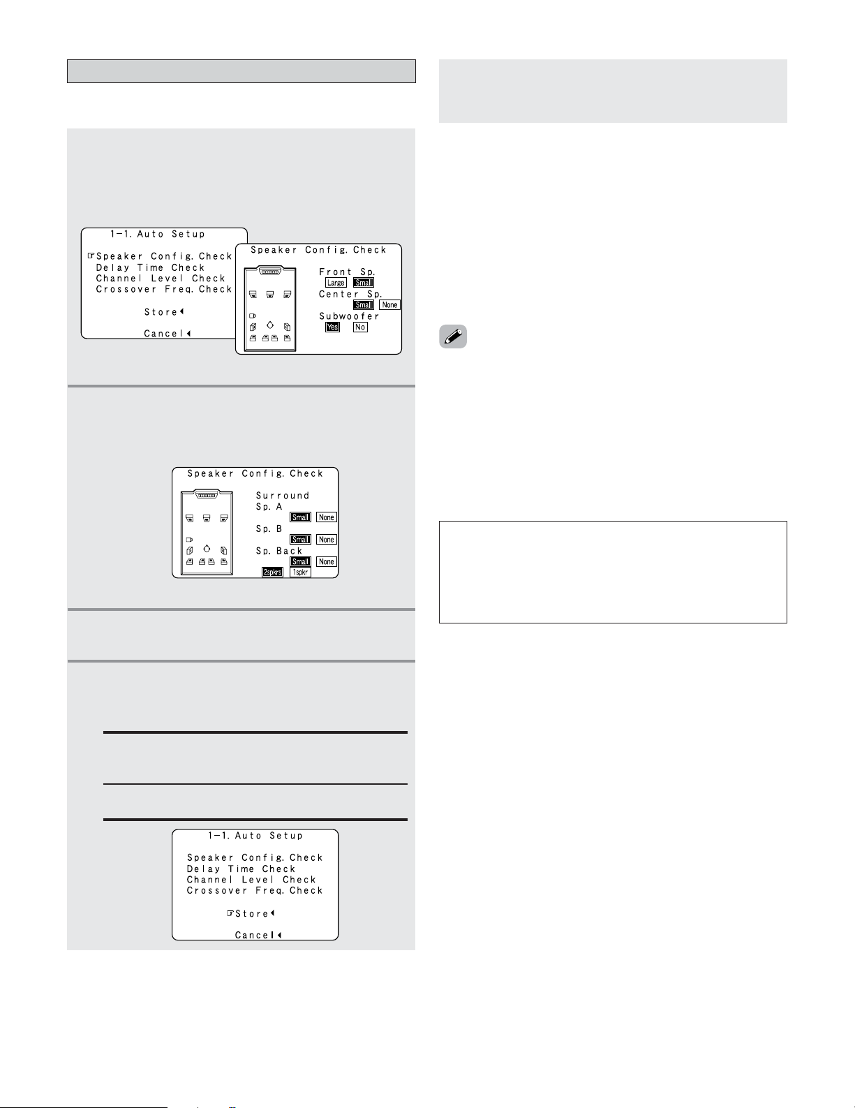
Easy Setup and Operation
Check of the measurement result
• The results of the measured items can be checked.
1
Press the CURSOR
DD
or
HH
button to select
items, then press the
ENTER button.
• Switch to the verification screen.
Example: Speaker Config. Check
2
Press the ENTER button.
• Switch to the second screen.
Example: Speaker Config. Check
[ First screen ]
[ Second screen ]
3
If the check ends, press the ENTER button
again.
• Sometimes due to the electrical complexities of subwoofers
and the interaction with the room, THX recommends setting
the level and the distance of the subwoofer manually.
• Sometimes due to interaction with the room, you may notice
irregular results when setting the level and/or distance of the
main speakers. If this happens, THX recommends setting
them manually.
• Please note that any THX main speakers should be set to
Small (80 Hz). If you set up your speakers using Auto Setup,
please make sure manually that any THX speakers are set to
Small with 80 Hz crossover.
Store:
Set with the checked measurement value.
All parameters are stored up.
Cancel:
Cancel the auto setup settings.
NOTE:
• Do not turn off the power while the data is being stored.
If the power is turned off while the data is being stored,
the Room EQ parameters stored in the memory will be
cleared, and it will not be possible to select “Audyssey”,
“Front” or “Flat” equalizer settings.
5
Press the CURSOR
FF
button.
•After the data is stored, the “Auto Setup / Room
EQ” menu appears automatically.
• When measurements have been made using the
measurement microphone, speakers with a built-in filter
such as subwoofers might be set with a value that differs
from the physical distance because of the internal electrical
delay.
• If the “Channel Setup” or “Power Amplifier Assignment”
settings are changed after completing the auto setup,
perform the auto setup procedure again. In the same way, if
the speaker layout has been changed, we recommended
performing the auto setup procedure over again.
4
Press the CURSOR
DD
or
HH
button to select
whether or not to save the data you have
checked.
MeasuresCauseScreen example
26
Easy Setup and Operation
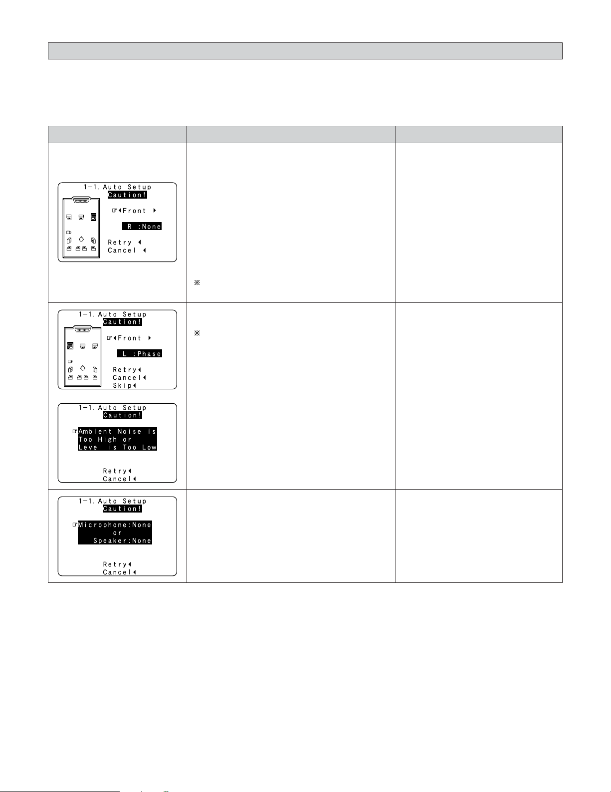
About the error message
• These error messages will be displayed when performing the measurements of Auto Setup and the automatic measurements
can not be completed because of the speaker arrangement, measurement environment, or other factors. Please check the
following matters, reset the pertinent items, and measure again. Be sure to turn off the AVR-5805CI’s power before checking
the speaker connections.
q The speakers required for producing suitable
reproduction have not been detected.
• The front L speaker was detected, but the
front R speaker was not detected.
• Only one channel of the surround (A) and
surround (B) speakers was detected.
• Sound was output from the R channel when
only one surround back speaker was
connected.
• The surround back or the surround (B) speaker
was detected, but the surround (A) speaker
was not detected.
If multiple errors occur, press the CURSOR
FF
or
GG
button to check the contents.
• Check that the pertinent speakers
are properly connected.
w The speaker polarity is connected in reverse.
If multiple errors occur, press the CURSOR
FF
or
GG
button to check the contents.
• Check the polarity of the pertinent
speakers.
• For some speakers, the screen
below may be displayed even though
the speakers are properly connected.
If so, select “Skip
0
”.
e There is too much ambient noise in the room
and the measurements cannot be made
accurately.
r The sound level that is output from the
speakers and/or subwoofer is too low.
• Either turn off the power of the
device that generated the noise
during the measurements or move
the device away.
•Try again at a time when it is quieter.
• Check the placement and orientation
of the loudspeakers.
• Adjust the subwoofer’s output level.
t The measurement microphone is not
connected, or all of speakers have not been
detected.
y The front L speaker was not detected.
• Connect the measurement microphone
to the SETUP MIC jack.
• Check the speaker connection.
Connecting Other Sources
27
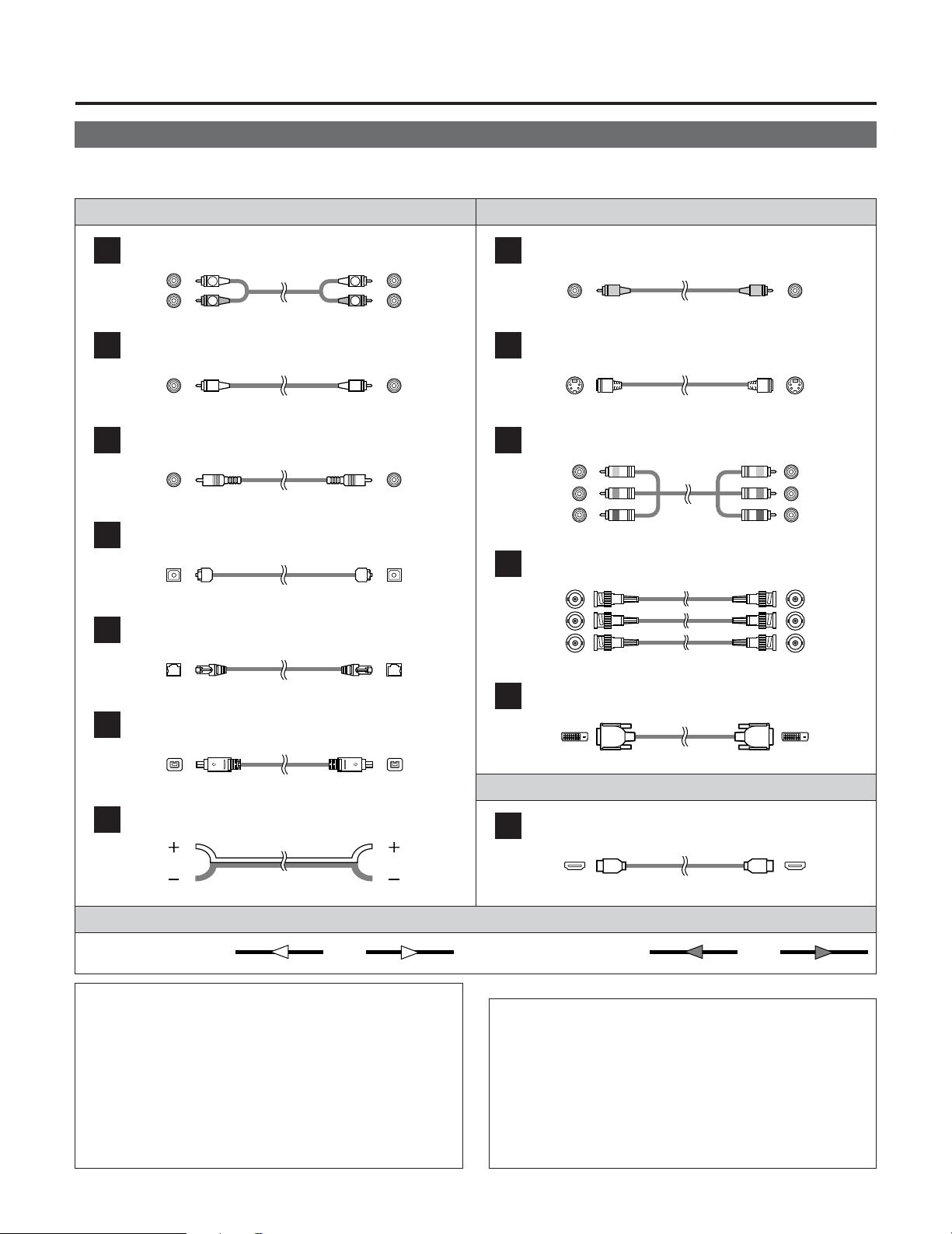
Cable indications
Signal direction
Audio and Video cable
• The hookup diagrams on the subsequent pages assume the use of the following optional connection cables (not supplied).
Video cableAudio cable
NOTE:
• Do not plug in the power supply cord until all connections
have been completed.
• When making connections, also refer to the operating
instructions of the other components.
• Be sure to connect the left and right channels properly
(left with left, right with right).
• Note that binding pin-plug cables together with power
supply cords or placing them near a power transformer
will result in generating hum or other noise.
Analog connections (Stereo)
A
R
L
R
L
(Orange)
(Green)
(Blue)
(Red)
Pin-plug cable
Analog connections (Monaural, for subwoofer)
B
Pin-plug cable
Digital connections (Coaxial)
C
Coaxial cable (75 Ω/ohms pin-plug cable)
Digital connections (Optical)
D
Optical cable (Optical fiber cable)
DENON LINK connections
E
DENON LINK cable
IEEE1394 connections
F
4-pin, S400 IEEE1394 cable
Speaker connections
G
Speaker cable
Video connections
H
Video cable (75 Ω/ohms video pin-plug cable)
S-Video connections
I
S-Video cable
Component video connections
J
Component video cable
DVI-D connections
L
24-pin DVI-D cable
HDMI connections
M
19-pin HDMI cable
(Yellow)
Audio signal Video signal
(Y)
(P
B
/C
B
)
(P
R
/C
R
)
IN OUT OUT ININ OUT OUT IN
(White)
(Red)
NOTE:
• Connecting a LD (laser disc) player with a Dolby
Digital RF Output
The AVR-5805CI does not have a DD RF demodulator
function. Therefore, you need to use a commercially
available outboard DD RF demodulator and connect its
digital output to one of the AVR-5805CI available digital
inputs. Refer to the demodulator’s operating instruction
for further information.
Component video connections
K
BNC (75 Ω/ohms) cable
(Y)
(P
B
/C
B
)
(P
R
/C
R
)
(Y)
(P
B
/C
B
)
(P
R
/C
R
)
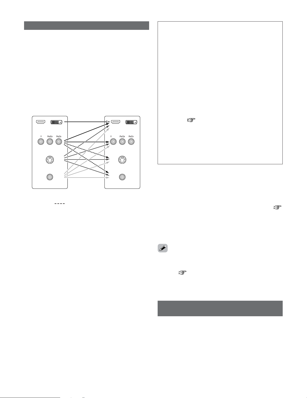
28
Connecting Other Sources
• The AVR-5805CI is equipped with a function for up and down
converting video signals.
Because of this, the AVR-5805CI’s MONITOR OUT terminal
can be connected to the monitor (TV) with a set of cables
offering a higher quality connection, regardless of how the
player and the AVR-5805CI’s video input terminals are
connected.
Generally speaking, analog video connections using the
component video terminals offer the highest quality
playback, followed by connections using the S-Video
terminals, then connections using the regular video
terminals (yellow).
The video conversion function
NOTE:
• It is not possible to down-convert from HDMI and DVI-D
input signals to the component, S-Video or composite
video monitor output terminals.
•Video down conversion to the MAIN ZONE’s monitor
output is only possible when the component video input
resolution is 480i (interlaced standard definition video –
NTSC format, for North America) or 576i (interlaced
standard definition video – PAL format, for Europe and
other countries).
• It is not possible to down-convert from the ZONE2’s
component video signal to a S-Video or composite signal,
so when not using the ZONE2’s component monitor
output terminal, use an S-Video connection cable or
composite connection cable to connect the AVR-5805CI
with the player.
•To set the video conversion function for the MAIN ZONE
to “OFF” ( page 112).
• Set the resolution of the video output to one that is
compatible with the resolution of your monitor.
• When “Component” is set at “Scaler” under
“HDMI/Component Out”, the signals are output to the
HDMI/DVI-D monitor output terminal with their original
resolution. Use a monitor compatible with a resolution of
480i/576i.
On screen display for component video
outputs and HDMI output
• When viewing component video signals or HDMI signals via
the AVR-5805CI, the on screen display is displayed on the
monitor when the “System Setup” operations are
performed and when the remote control unit’s ON SCREEN
button is operated.
•To view the on screen display using an HDMI monitor, set
“Analog to HDMI Convert” at “HDMI/Component Out” to
“ON” (default).
• When only component video signals are input to the AVR-
5805CI, the characters of the on screen display are not
displayed over the picture.
2
The analog video to HDMI conversion function:
The AVR-5805CI’s video up-conversion function lets you
output analog video input signals (component – 480i/576i,
480p/576p, 1080i or 720p; S-Video and composite video -
480i/576i) to the HDMI monitor output terminal.
•With the AVR-5805CI, the resolution of the signal output to
the HDMI MONITOR OUT terminal can be selected (
page 113, 114). The resolutions with which the monitor is
compatible can be checked using the STATUS button on the
main unit or the ON SCREEN button on the remote control unit.
• The resolution of the signal output to the component
monitor output terminal can be set on the AVR-5805CI.
• If you do not want to use the function for converting analog
video signals to HDMI signals, select “OFF” for “Analog to
HDMI Convert” at “Setting the HDMI/Component Out
Setup”( page 113, 114).
In this case, the function for video up conversion to the
component video terminal operates.
Cautions on the ZONE2 video conversion function:
• There is no TBC (Time Base Collector) for ZONE2.
When the component video terminals are used to connect
the AVR-5805CI with a TV (or monitor, projector, etc.) and
the video (yellow) or S-Video terminals are used to connect
the AVR-5805CI with a VCR, depending on the combination
of the TV and VCR the picture may flicker in the horizontal
direction, be distorted, be out of sync or not display at all
when playing video tapes.
If this happens, connect a commercially available video
stabilizer, etc., with a TBC (time base corrector) function
between the AVR-5805CI and the VCR, or if your VCR has
a TBC function, turn it on.
The flow of the video signals.
AVR-5805CI’s input terminals AVR-5805CI’s output terminals
Component video
terminals
S-Video terminal
Video terminal
Component video
terminals
(MONITOR OUT/ZONE2)
S-Video terminal
(MONITOR OUT/ZONE2)
Video terminal
(MONITOR OUT/ZONE2)
HDMI / DVI-D
terminals
HDMI / DVI-D
terminals
: only MAIN ZONE 480i/576i
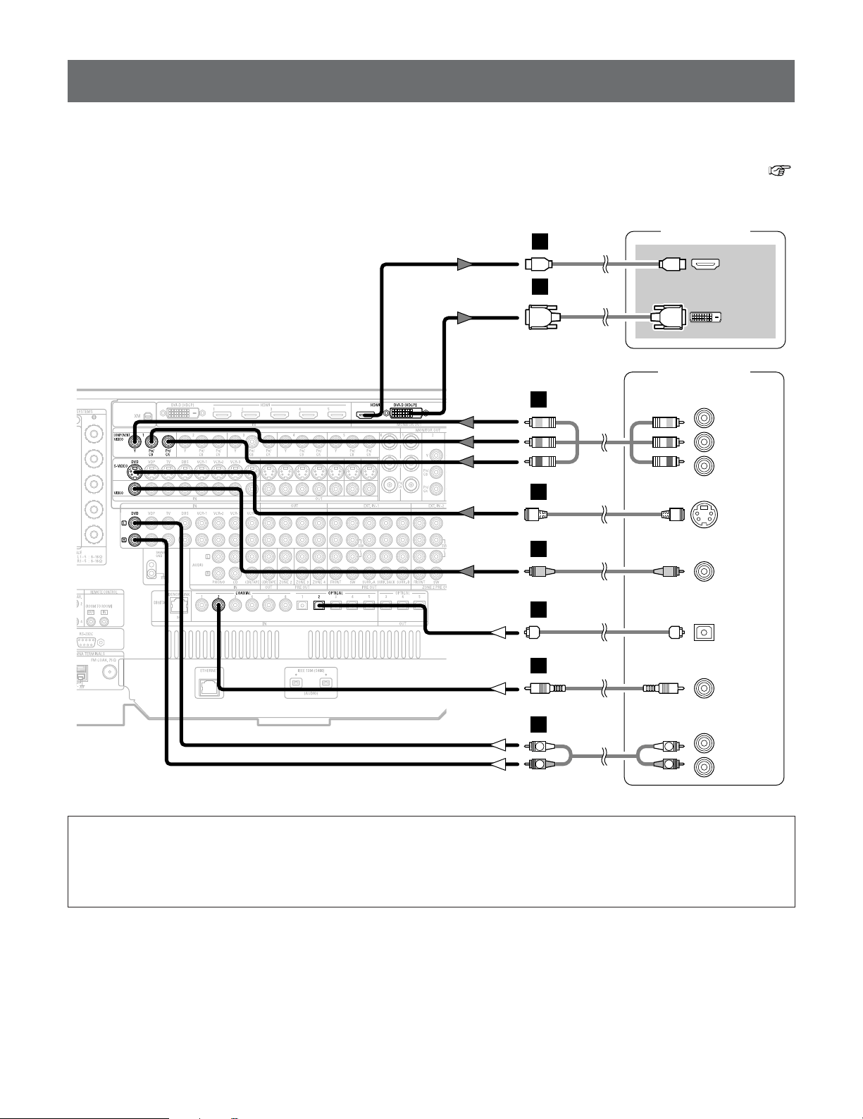
29
Connecting Other Sources
Connecting equipment with HDMI terminals
[To convert analog video signals to HDMI signals]
DVD player
S VIDEO
OUT
COAXIAL
OUT
R
L
AUDIO OUT
VIDEO
OUT
COMPONENT VIDEO OUT
Y
P
B
PR
OPTICAL
OUT
TV (Monitor)
HDMI
IN
DVI-D
IN
or
R
L
R
L
H
J
I
A
C
D
M
L
• The AVR-5805CI is equipped with a function for converting analog video signals into HDMI signals.
You can do this by either a component or a video or a S-Video connection.
• Audio signals are not output from the HDMI monitor output terminal, so also make analog or digital audio connections. To play
sound using digital audio connections, assign the digital terminal (coaxial or optical) at “Setting the Digital In Assignment” (
page 104).
NOTE:
• When “Through” is set at “Resolution” under “Setting the HDMI/Component Out Setup”, use a monitor compatible with
input resolutions of 480i/576i.
• If your monitor is not equipped with an HDMI terminal, connect the AVR-5805CI to the monitor using the component
video, S-Video, or composite video terminals.
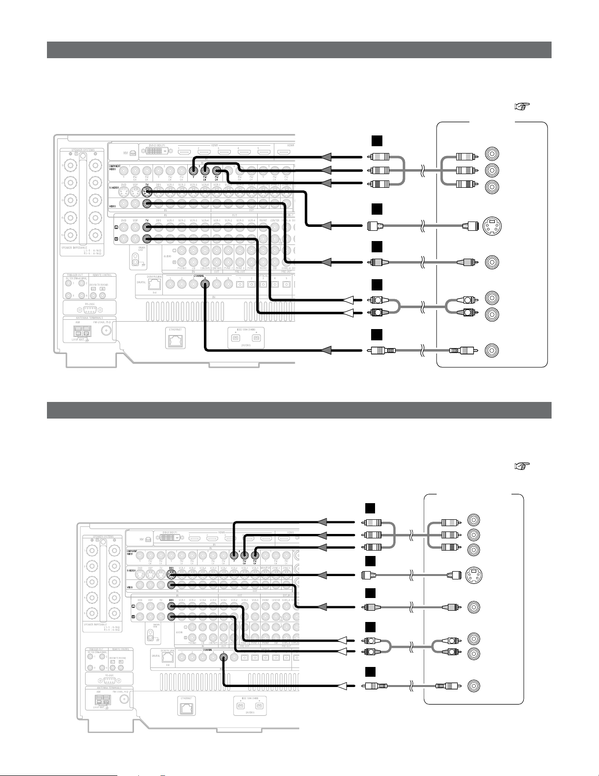
30
Connecting Other Sources
Connecting a DBS tuner
Connecting a TV tuner
H
I
A
TV tuner
S VIDEO
OUT
R
L
AUDIO OUT
VIDEO
OUT
COMPONENT VIDEO OUT
Y
P
B
PR
COAXIAL
OUT
R
L
R
L
J
C
DBS / BS Tuner
S VIDEO
OUT
COAXIAL
OUT
R
L
AUDIO OUT
VIDEO
OUT
R
L
R
L
H
I
A
C
COMPONENT VIDEO OUT
Y
P
B
PR
J
• For best picture quality choose the component video connection to your DBS tuner. S-Video and composite video outputs are
also provided if your DBS tuner does not have component video inputs.
•To connect the digital audio output from the DBS tuner, you can choose from either the coaxial or optical connections. If you
choose to use the optical connection, it needs to be assigned. For more information about Digital Input Assignment ( page
104).
• For best picture quality choose the component video connection to your TV tuner. S-Video and composite video outputs are also
provided if your TV tuner does not have component video inputs.
•To connect the digital audio output from the TV tuner, you can choose from either the coaxial or optical connections. If you
choose to use the optical connection, it needs to be assigned. For more information about Digital Input Assignment ( page
104).
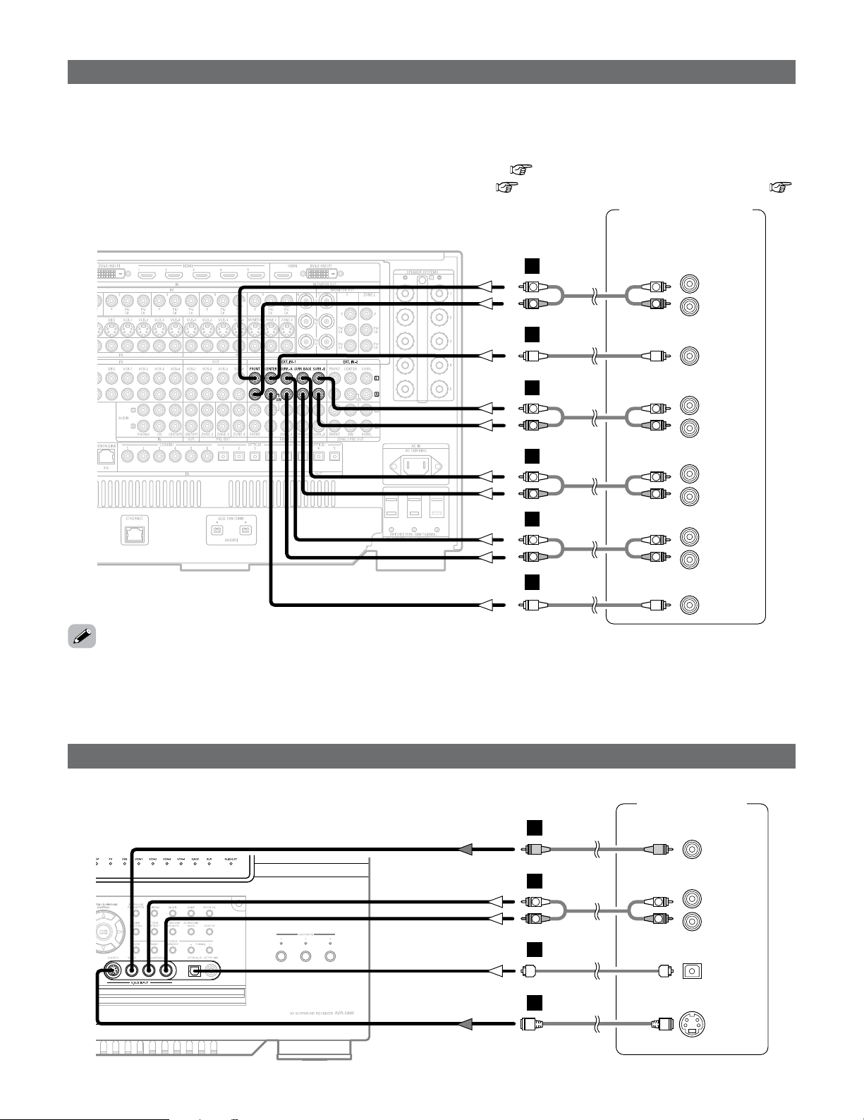
31
Connecting Other Sources
Connecting the external inputs (EXT. IN) terminals
External decoder 1
DVD-Audio-Video /
Super Audio CD Player
R
SURROUND B
L
R
SURROUND
BACK
L
R
SURROUND A
L
R
FRONT
L
9.1ch AUDIO OUT
CENTER
SUB-
WOOFER
L
R
L
R
R
L
R
L
B
A
B
A
R
L
R
L
A
R
L
R
L
A
•AVR-5805CI is equipped with two analog external input terminals for 9.1 channels and 5.1 channels.
• These terminals are for inputting multi-channel audio signals from an outboard decoder, or a component with a different type of
multi-channel decoder, such as a DVD-Audio player, or a multi-channel Super Audio CD player, or other future multi-channel
sound format decoder.
• The method of video signal connection is the same as that for DVD player ( page 18).
• For instructions on playback using the external input (EXT. IN) terminals ( page 47) and “Setting the EXT. IN Setup” (
page 105).
• The EXT. IN-2 terminal can be connected for 5.1-channels (FL, FR, C, SL, SR and SW) in the same way as the EXT. IN-1 terminal.
•With discs on which special copyright protection measures have been taken, however, the digital signals may not be output
from the DVD player. In this case, connect the DVD player’s analog multi-channel output to the AVR-5805CI’s EXT. IN terminals
for playback. Also refer to your DVD player’s operating instructions.
Connecting a video camera or video game
Video camera /
Video game
S VIDEO
OUT
R
L
AUDIO OUT
VIDEO
OUT
OPTICAL
OUT
R
L
R
L
F
G
A
D
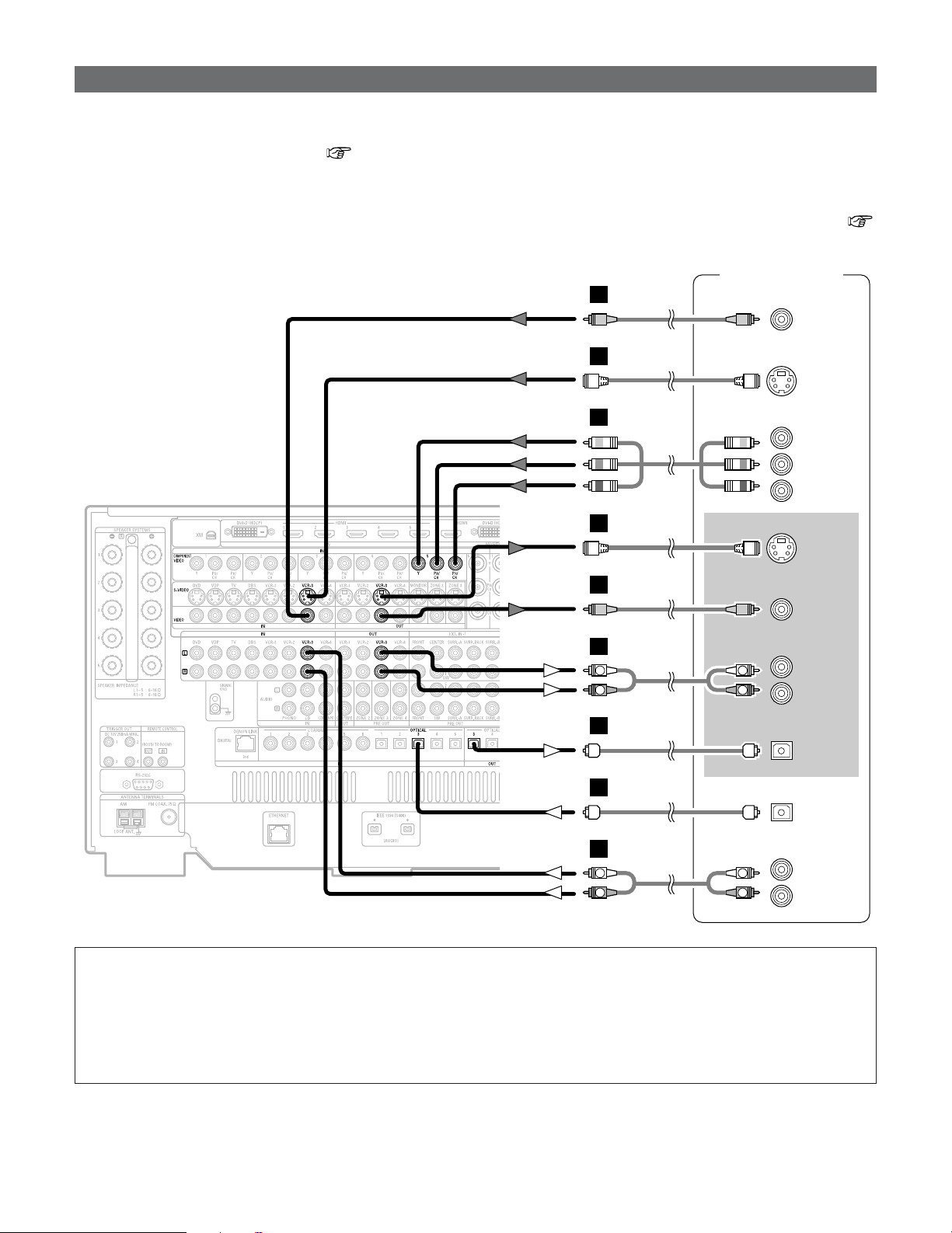
32
Connecting Other Sources
Connecting a DVD recorder
DVD recorder
S VIDEO
OUT
S VIDEO
IN
R
L
AUDIO IN
R
L
AUDIO OUT
VIDEO
OUT
VIDEO
IN
OPTICAL
IN
OPTICAL
OUT
R
L
R
L
H
H
I
I
A
R
L
R
L
A
D
D
COMPONENT VIDEO OUT
Y
P
B
PR
J
• For best picture quality choose the component video connection to your DVD recorder. S-Video and composite video outputs
are also provided. If you choose to use the component video or BNC connection, it needs to be assign. For more information
about Component Input Assignment ( page 112).
• If you wish to perform analog dubbing from a digital sources, such as a DVD recorder to an analog recorder such as a cassette
deck, you will needs connect analog inputs and outputs as shown below, in addition to the digital audio connections.
•To connect the digital audio output from the DVD recorder, you can choose from either the coaxial or the optical connections.
If you choose to use the coaxial connection, it needs to be assigned. For more information about Digital Input Assignment (
page 104).
NOTE:
•When recording to DVD recorder, it is necessary that the type of cable used with the playback source equipment be the
same type that is connected to the AVR-5805CI VCR-1 (to 4) OUT terminal.
Example: TV IN
→ S-Video cable : VCR-1 to 4 OUT→ S-Video cable
TV IN → Video cable : VCR-1 to 4 OUT→ Video cable
• Do not connect the output of the component connected to the OPTICAL 3 (to 5) OUT terminal on the AVR-5805CI’s rear
panel to any terminal other than the OPTICAL 3 (to 5) IN terminal.
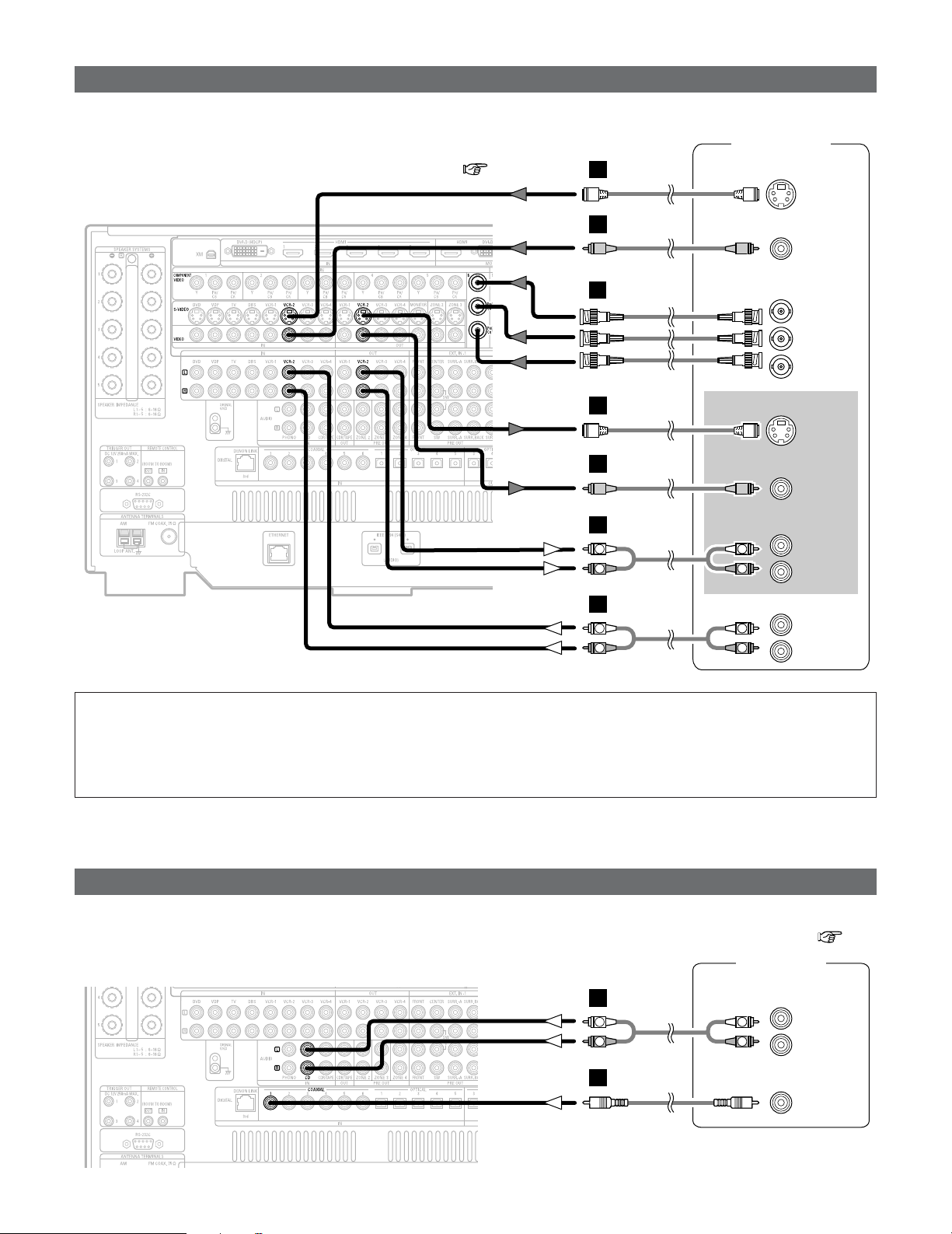
33
Connecting Other Sources
Connecting a CD player
R
L
AUDIO OUT
CD player
COAXIAL
OUT
R
L
R
L
A
C
Connecting a VCR
Video deck
S VIDEO
IN
R
L
AUDIO IN
R
L
AUDIO OUT
VIDEO
IN
S VIDEO
OUT
VIDEO
OUT
COMPONENT VIDEO OUT
Y
PB
PR
R
L
R
L
H
I
H
I
A
R
L
R
L
A
K
• There are three sets of video deck (VCR) terminals, so three video decks can be connected for simultaneous recording or video
copying.
• If you choose to use the component video connection, it needs to be assign.
For more information about Component Input Assignment ( page 112).
•To connect the digital audio output from the CD player, you can choose from either the coaxial or optical connections. If you
choose to use the optical connection, it needs to be assigned. For more information about Digital Input Assignment ( page
104).
NOTE:
•When recording to VCR, it is necessary that the type of cable used with the playback source equipment be the same type
that is connected to the AVR-5805CI VCR-1 (to 4) OUT terminal.
Example: VCR-1 IN → S-Video cable : VCR-2 OUT→ S-Video cable
VCR-2 IN → Video cable : VCR-1 OUT→ Video cable
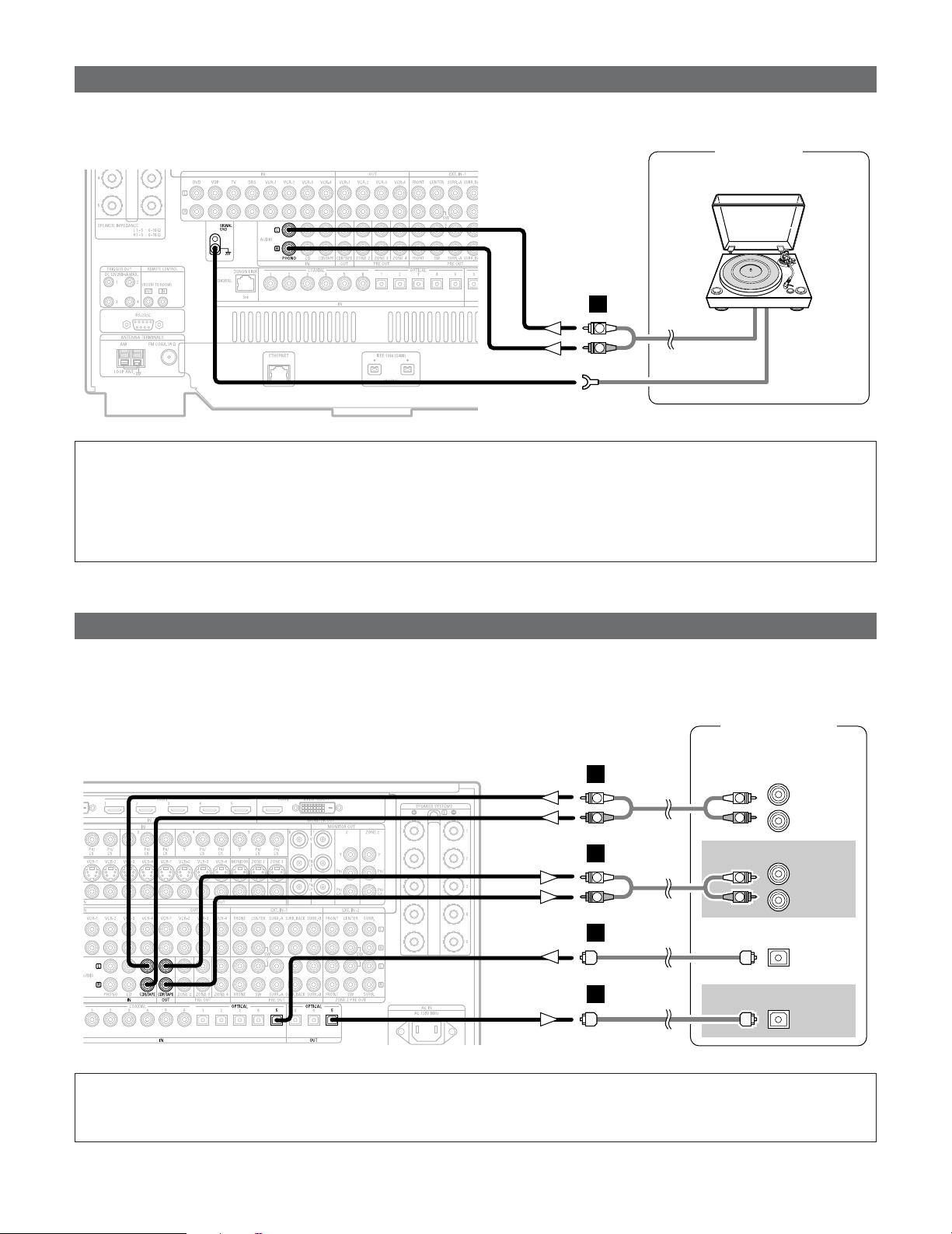
34
Connecting Other Sources
Connecting a CD recorder or MD recorder
R
L
AUDIO IN
R
L
AUDIO OUT
CD recorder /
MD recorder
OPTICAL
OUT
OPTICAL
IN
R
L
R
L
A
R
L
R
L
A
D
D
Connecting a turntable
AUDIO OUT
GND
Turntable
(MM cartridge)
R
L
A
•You can connect the turntable (MM cartridge) to the PHONO terminals.
NOTE:
• The phono input can accept signals from moving magnet (MM) and high output moving coil (MC) phono cartridges. If your
turntable is equipped with a low output MC cartridge, you will need to use a separate MC head amplifier or step-up MC
transformer.
• If humming or other noise is generated when the ground wire is connected to the SIGNAL GND terminal, disconnect the
ground wire.
• If you wish to perform analog dubbing from a digital source, such as a CD or MD recorder to an analog recorder such as a
cassette deck, you will need to connect analog inputs and outputs as shown below, in addition to the digital audio connections.
NOTE:
• Do not connect the output of the component connected to the OPTICAL 5 OUT terminal on the AVR-5805CI’s rear panel
to any terminal other than the OPTICAL 5 IN terminal.
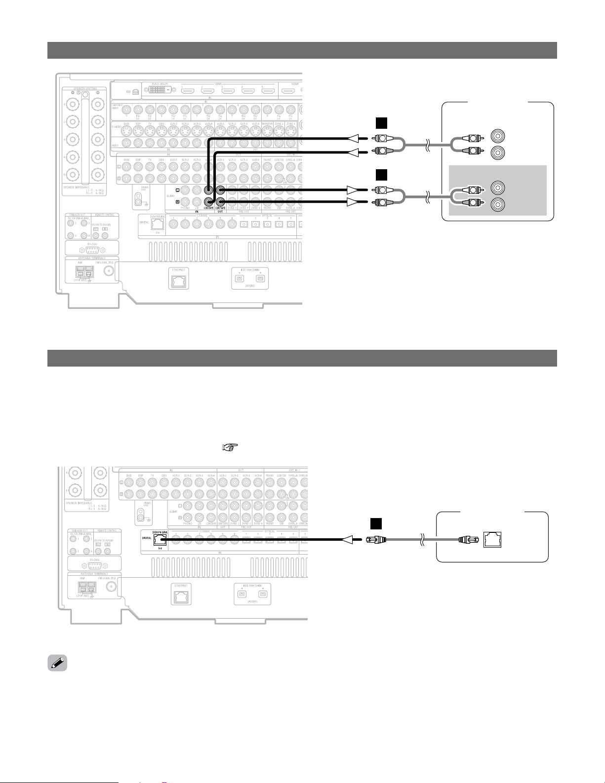
35
Connecting Other Sources
Connecting a tape deck
R
L
AUDIO IN
R
L
AUDIO OUT
Tape deck
R
L
R
L
A
R
L
R
L
A
DENON LINK connection
DVD player
DENON
LINK
E
• High quality digital sound with reduced digital signal transfer loss can be enjoyed by connecting a separately sold DENON LINK
compatible DVD player.
• Digital transfer and multi-channel playback of DVD-Audio discs and other multi-channel sources is possible by connecting the
AVR-5805CI to a DENON DVD player equipped with a DENON LINK connector using the connection cable included with the
DVD player.
• When a DENON DVD player and the DENON LINK have been connected, be sure to make a setting to “DENON LINK” with
the System Setup Digital In Assignment ( page 104).
•With discs on which special copyright protection measures have been taken, however, the digital signals may not be output
from the DVD player. In this case, connect the DVD player’s analog multi-channel output to the AVR-5805CI’s EXT. IN terminals
for playback.
Also refer to your DVD player’s operating instructions.
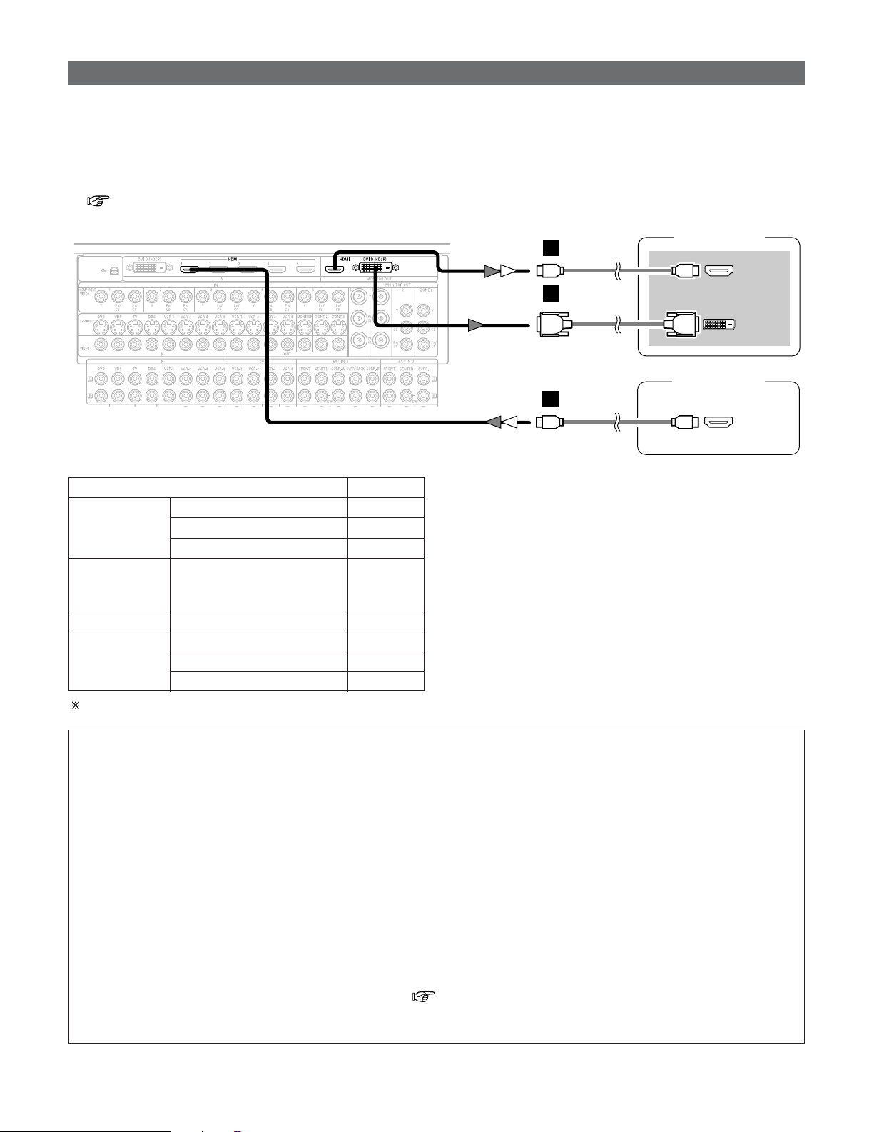
36
Connecting Other Sources
Connecting equipment with HDMI terminals
DVD player
HDMI
OUT
TV (Monitor)
HDMI
IN
DVI-D
IN
or
M
M
L
•A simple 1-cable connection (using a commercially available cable) with a device having an HDMI (High-Definition Multimedia
Interface) terminal allows digital transfer of the digital images of DVD-Video and other sources, and the multi-channel sound of
DVD-Audio and DVD-Video.
•The HDMI and DVI-D monitor output terminals on the AVR-5805CI can only be used one at a time, not simultaneously.
•To provide audio output from AVR-5805CI’s audio output terminal, select “AMP” at the System Setup.
To provide audio output from the TV, select “TV” at the System Setup. For details, see “Setting the HDMI/DVI In Assignment”
( page 111, 112).
CC
DVD-Video
Input signals
LINEAR PCM
DTS
Dolby Digital
DVD-Audio
CC
LINEAR PCM
PACKED PCM
(with CPPM / without CPPM)
CC
CC
CC
CD LINEAR PCM
EE
Super Audio
CD
Multi area
CD area
Stereo area
EE
CC
2 Copyright Protection System
To play back the digital video and audio of DVD-Video and
DVD-Audio through an HDMI/DVI-D connection, both the
connected player and monitor are required to support a
copyright protection system called HDCP (High-bandwidth
Digital Content Protection System). HDCP is copy
protection technology that comprises data encryption and
authentication of the partner equipment.
The AVR-5805CI supports HDCP. Please see the operating
instruction of your video display for more information
about this.
NOTE:
• The audio signals on the multi/stereo area of Super Audio CDs are not output. If the Super Audio CD is a hybrid CD, only
the audio signals in the CD area are output.
• Use a compatible player to play DVD-Audio discs that are copyright protected by CPPM.
• Among the devices that support HDMI, some devices can control other devices via the HDMI cable; however, the AVR-
5805CI cannot be controlled by another device via the HDMI cable.
• The audio signals from the HDMI terminal (including the sampling frequency and bit length) may be limited by the
equipment that is connected.
• The video signals are not output properly if a device not compatible with HDCP is used.
• When “Through” is set at “Resolution” under “Setting the HDMI/Component Out Setup”, use a monitor compatible with
input resolutions of 480i/576i.
• The video signals input from the HDMI or DVI-D input terminals are output to the HDMI monitor with their original
resolution, so the image will not be displayed if the resolutions of the input signal and the monitor being used are not
matched. In this case, change the setting of the resolution on the source device (player) to one which the monitor can
handle.
• The sound may be interrupted if the monitor’s power is turned off when the HDMI audio signal’s playback method is set
to “AMP” at “Setting the HDMI/DVI In Assignment” ( page 111, 112).
• Use a cable including the HDMI logo (HDMI certified product) for connection of the HDMI terminal. Normal playback may
not be possible if a cable that does not include the HDMI logo (non-HDMI-certified product) is used.
The AVR-5805CI is HDMI Ver. 1.1 compatible.
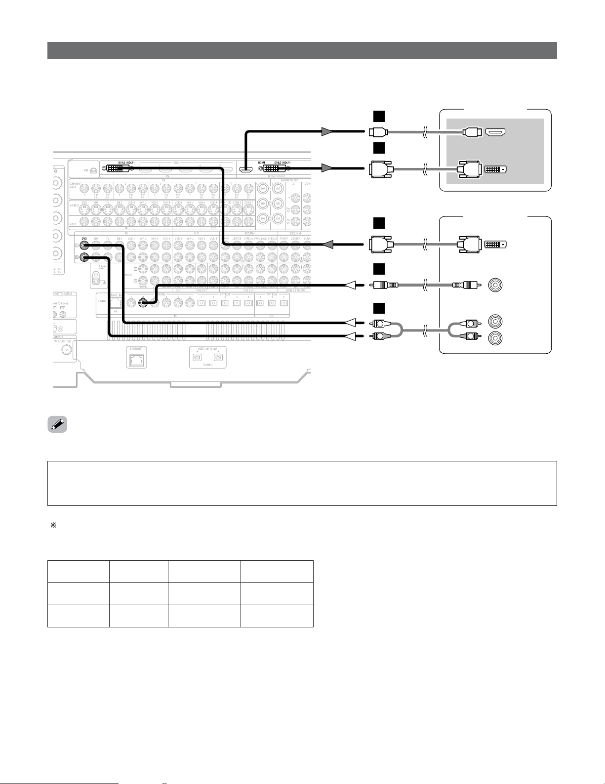
37
Connecting Other Sources
Connecting equipment with DVI-D terminals
DVD player
TV (Monitor)
HDMI
IN
DVI-D
OUT
DVI-D
IN
COAXIAL
OUT
L
M
L
C
R
L
AUDIO OUT
R
L
R
L
A
or
• Connection with equipment that has a DVI-D (Digital Visual Interface)-D terminal permits the transfer of digital images. Make an
analog or digital audio connection also.
• The HDMI and DVI-D monitor output connectors on the AVR-5805CI can only be used one at a time, not simultaneously.
NOTE:
• Commercially-available DVI-D cables are available in 24-pin and 29-pin types. The AVR-5805CI supports the 24-pin DVI-D cable.
• The AVR-5805CI supports HDCP. Use an HDCP-compatible HDMI monitor.
• When connecting via a DVI-D cable, no digital audio will be output from the HDMI monitor out terminal.
Note on connecting a HDMI/DVI-D
The table below indicates the compatibility of connections between the HDMI/DVI-D output terminal of the AVR-5805CI and
monitors that support HDMI/DVI-D.
E
E
HDMI output
terminal
Monitor with
HDMI
C
(Video / Audio)
C
(Only Video)
DVI-D output
terminal
Monitor with DVI-D
(HDCP compatible)
C
(Only Video)
C
(Only Video)
Monitor with DVI-D
(HDCP incompatible)
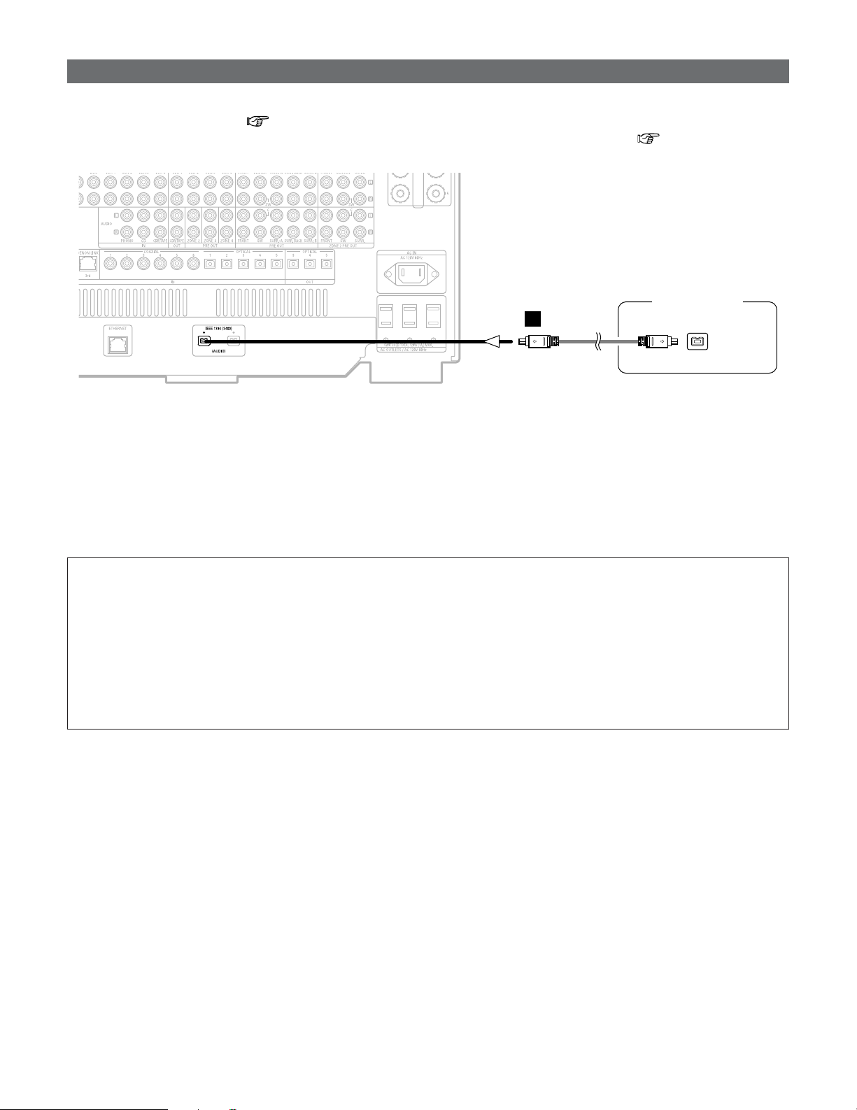
38
Connecting Other Sources
Connecting IEEE1394 devices
DVD player
IEEE1394
F
• For the digital transfer of signals from Super Audio CDs and DVD-Audio discs, connect using an IEEE1394 cable. For instructions
on playing Super Audio CDs ( page 99).
• Assign the IEEE1394 input the input source. For details, see “Setting the IEEE1394 Assignment” ( page 107).
2 IEEE1394 network
q Up to 17 devices can be connected using daisy chain type connections.
w Up to 63 devices can be connected using tree type connections.
Do not loop the connections.
e “LINK CHECK” is displayed when an input source to which an IEEE1394 is assigned is selected and connection to the
IEEE1394 device is being checked.
r If the connection is looped, “LOOP CONNECT” is displayed. Check the connections and undo the loop.
NOTE:
• Do not use an IEEE1394 cable to connect the AVR-5805CI with a computer.
• The AVR-5805CI will not operate when connected to equipment other than that conforming to “IEEE1394 AUDIO (A&M
protocol)” standards or when connected to computer peripherals.
Also please note that operation is not guaranteed even when connected to IEEE1394-compatible equipment. Whether or
not data and control signals can be sent and received between interconnected IEEE1394-compatible equipment depends
on the functions of the different equipment. Please read the operating instructions of the equipment to be connected.
• Use an S400-compatible 4-pin IEEE1394 cable to connect.
•Video signals are not transferred with the AVR-5805CI’s IEEE1394 interface, so when connecting a video device connect
the video signals as well.
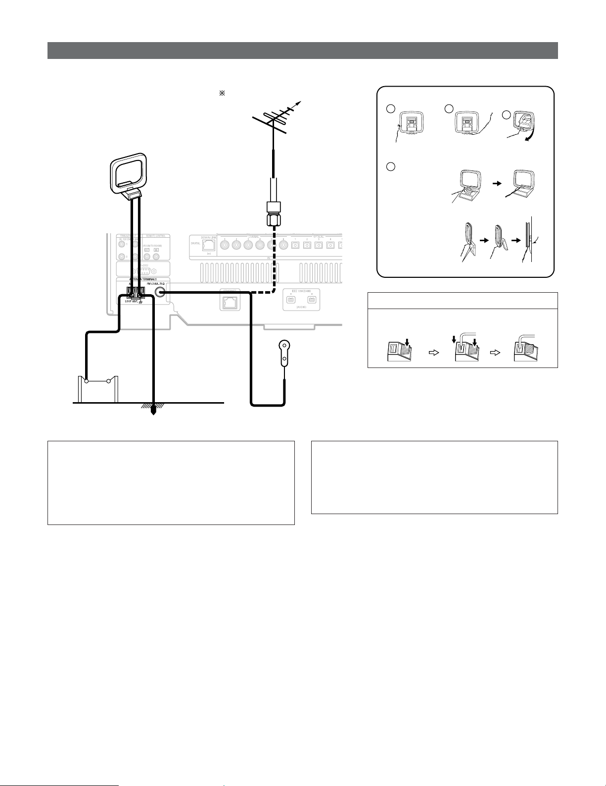
39
Connecting Other Sources
Connecting the antenna terminals
Direction of broadcasting
station
75 Ω/ohms
COAXIAL
CABLE
FM ANTENNA
FM INDOOR
ANTENNA
(Supplied)
AM LOOP ANTENNA
(Supplied)
AM OUTDOOR
ANTENNA
GROUND
1
4
2
3
2 AM loop antenna assembly
Connect to the AM
antenna terminals.
Remove the vinyl tie
and take out the
connection line.
Bend in the reverse
direction.
a. With the antenna
on top any stable
surface.
b. With the antenna
attached to a wall.
Mount
Installation hole Mount on wall, etc.
Connection of AM antennas
1. Push the lever. 2. Insert the
conductor.
3. Return the
lever.
NOTE:
• Do not connect two FM antennas simultaneously.
• Even if an external AM antenna is used, do not disconnect
the AM loop antenna.
•Make sure AM loop antenna lead terminals do not touch
metal parts of the panel.
• An F-type FM antenna cable plug can be connected directly.
Note to CATV system installer
• This reminder is provided to call the CATV system
installer’s attention to Article 820-40 of the NEC which
provides guidelines for proper grounding and, in particular,
specifies that the cable ground shall be connected to the
grounding system of the building, as close to the point of
cable entry as practical.
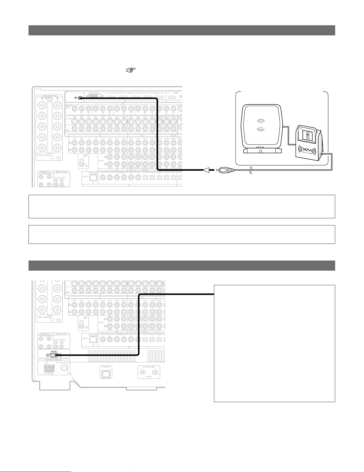
40
Connecting Other Sources
Connecting the CONTROL terminal
This terminal is used for an external
controller.
Perform the following operation before using
an external controller connected to the RS-
232C terminal:
1. Press the ON/STANDBY button on the
main unit and set the unit to the
operating mode.
2. Perform the operation to turn off the
power from the external control.
3. Check that the product has been set to
the standby mode.
After checking the above, check the
connections of the external controller.
Operation is possible.
Connecting the XM terminal
•AVR-5805CI is the XM Ready
®
receiver. You can receive XM
®
Satellite Radio by connecting to the XM Mini-Tuner and Home
Dock (includes home antenna, sold separately) and subscribing to the XM service.
•Plug the XM Mini-Tuner Home Dock into XM terminal on the rear panel.
• Position the Home Dock antenna near a south-facing window to receive the best signal.
For details, see “XM Satellite Radio” ( page 71).
When making connections, also refer to the operating instructions of the XM Mini-Tuner and Home Dock.
XM Mini-Tuner and Home Dock
MX
NOTE:
• Keep the power supply cord unplugged until the XM Mini-Tuner and Home Dock connection has been completed.
• The XM name and related logo are registered trademarks of XM Satellite Radio Inc. All rights reserved.
• XM Ready is a registered trademark of XM Satellite Radio Inc. All rights reserved.
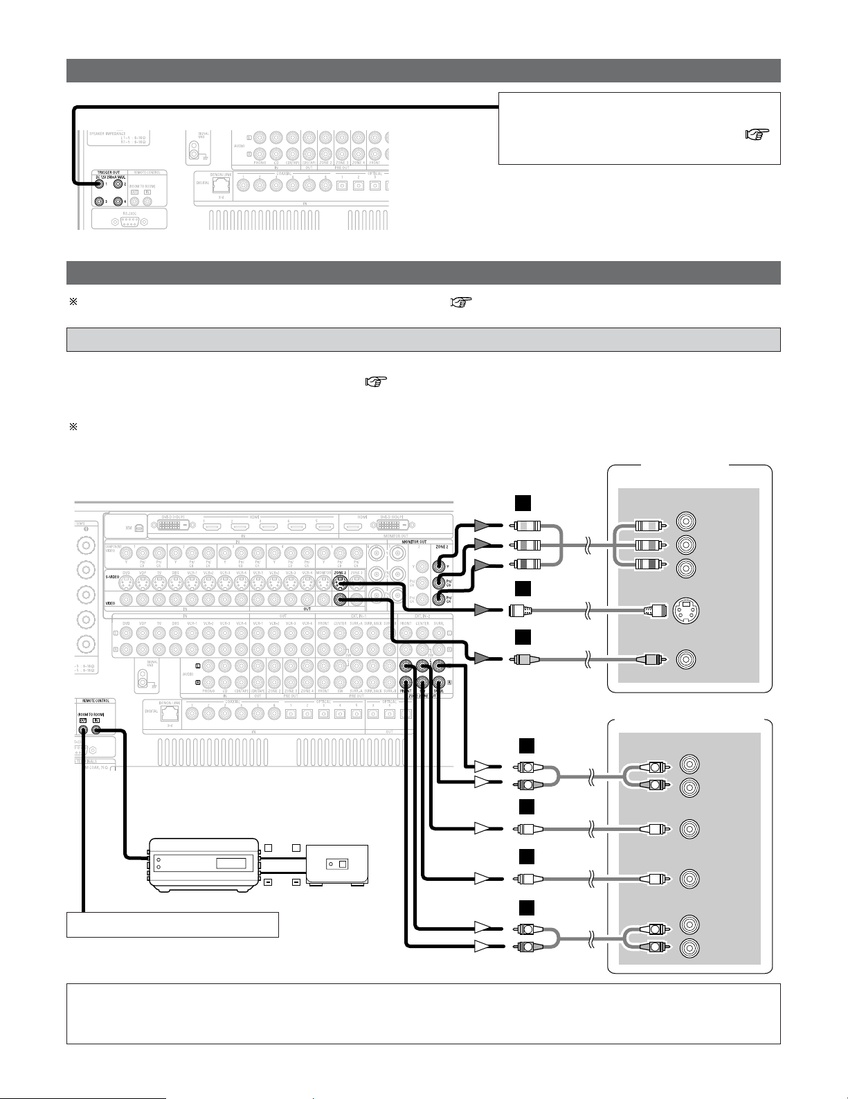
41
Connecting Other Sources
Connecting the TRIGGER OUT terminals
Turn the DC 12 V voltage on and off for the
individual functions and surround modes.
For details, see “Setting the Trigger Out” (
page 135).
Connecting the MULTI ZONE terminals
TV (Monitor)
(ZONE2)
S VIDEO
IN
VIDEO
IN
+
+
INFRARED SENSOR
INFRARED RETRANSMITTER
INPUT OUTPUT
AUX OUT
COMPONENT VIDEO IN (ZONE2)
Y
PB
PR
Power amplifier (ZONE2)
R
SURROUND
L
R
FRONT
L
5.1ch AUDIO IN
CENTER
SUB-
WOOFER
H
I
J
B
B
R
L
R
L
A
R
L
R
L
A
For instructions on operations using the MULTI ZONE functions ( page 87 ~ 98).
ZONE2 connections
• It is possible to connect a separate amplifier to the AVR-5805CI and simultaneously listen to a different program source than that
in the MAIN ZONE in a different room (ZONE2/3/4) ( page 88 ~ 92).
• The ZONE2 video out is only for the ZONE2.
The diagram below shows an example of connections for performing surround playback in ZONE2. For 2 channel
connections in ZONE2 and for ZONE3 and ZONE4 connection examples, see pages 87 ~ 92.
Extension terminals for future use.
NOTE:
• For the AUDIO output, use high quality pin-plug cables and wire in such a way that there is no humming or noise.
• For instructions on installation and operation of separately sold devices, refer to the devices’ operating instructions.

42
Connecting Other Sources
Connecting the power supply cord
AC 120 V, 60 Hz
AC outlet (wall)
Power supply cord
(Supplied)
NOTE:
• Only use the AC OUTLETS for audio equipment. Never use them for hair driers, TVs or other electrical appliances.
•
Insert the plugs securely. Incomplete connections will result in the generation of noise.
AC OUTLETS
• SWITCHED (total capacity – 120 W (1 A.))
The power to these outlets is turned on and off in
conjunction with the POWER switch on the main unit,
and when the power is switched between on and
standby from the remote control unit.
No power is supplied from these outlets when this
unit’s power is at standby. Never connect equipment
whose total capacity is above 120 W (1 A.)
Connecting the pre-out terminals
Power amplifier
R
SURROUND
BACK
L
R
SURROUND B
L
R
SURROUND A
L
R
FRONT
L
9.1ch AUDIO IN
CENTER
SUB-
WOOFER
L
R
L
R
R
L
R
L
B
A
B
A
R
L
R
L
A
R
L
R
L
A
• Use these terminals if you wish to connect external power amplifier(s) to increase the power of the front, center, surround and
surround back sound channels, or for connection to powered loudspeakers.
• When using only one surround back speaker, connect it to left channel.
• The AC outlets can be set to turn on and off for the different functions.
For details, see “Setting the AC Outlet Assignment” ( page 136).
• By changing the MAIN ZONE channel settings, up to three subwoofers can be connected to the AVR-5805CI.
For more information about “Setting the Channel Setup” ( page 126 ~ 128).
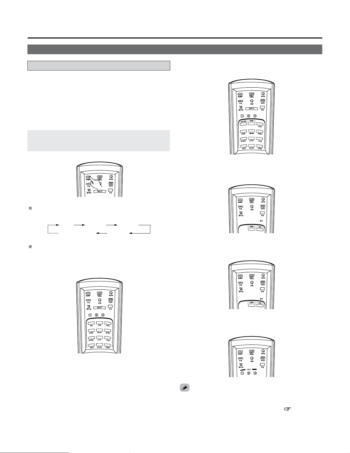
Basic Operation
43
Operating the remote control unit
• The RC-1036 remote control has a backlit EL display whose
contents change according to the mode or function selected,
with the appropriate remote commands for that mode or
function.
Playback
2 Operate the this unit
The AMP button is the main mode for controlling
the AVR-5805CI in the main room (MAIN ZONE).
The function switches as shown below each time one of
the AMP button is pressed.
AMP
SYSTEM CALL
ZONE2 ZONE3
ZONE4
2 AMP mode
To operate the MAIN ZONE function.
2
ZONE2 mode
To operate the ZONE2 function.
2 ZONE3 mode
To operate the ZONE3 function.
2
SYSTEM CALL mode
To operate the “System call” function.
• This function provides the ability to program a series of
individual remote control codes into a macro stored under
one of the number pad’s numeric choices ( page 84, 85).
The EL display switches as shown below with respect to
the selected mode.
2 ZONE4 mode
To operate the ZONE4 function.
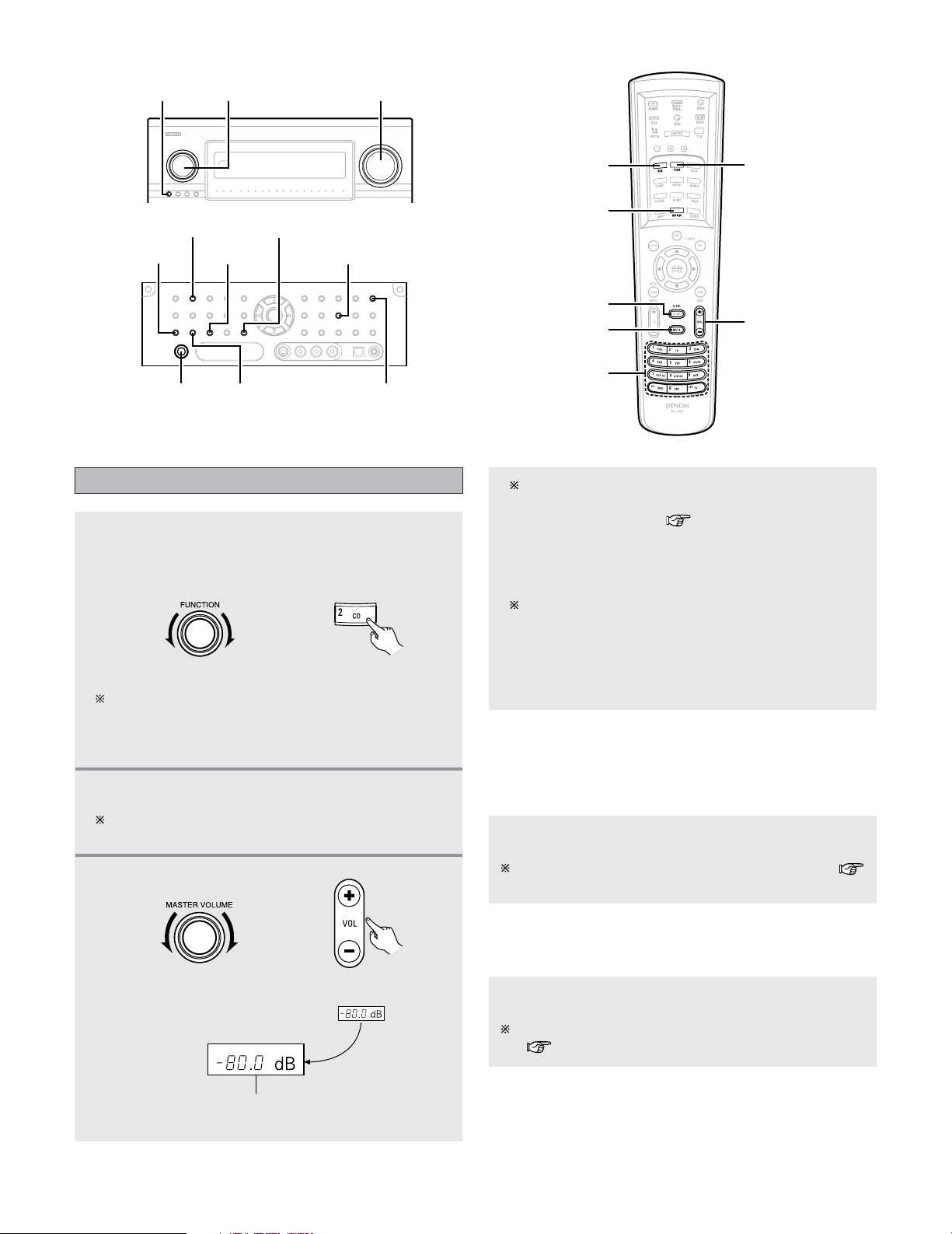
44
Basic Operation
Playing the input source
1
Select the input source to be played.
• The input source indicator lights.
Example: CD
(Main unit) (Remote control unit)
To select the input source when ZONE2 SELECT,
ZONE3/4/REC SELECT or TUNING PRESET is
selected, press the SOURCE button on the main unit
then operate the FUNCTION konb.
MATER VOLUME
SOURCE FUNCTION
MATER VOLUME
HOME THX
CINEMA
ROOM EQ
SPEAKER
MUTE
VIDEO SELECT
FUNCTION
2
Start playback on the selected component.
For operating instructions, refer to the component’s
manual.
3
Adjust the volume.
The volume can be adjusted within the range of –80.0
to +18.0 dB, in steps of 0.5 dB. However, when the
channel level is set ( page 64, 65 or 134), if the
volume for any channel is set at +0.5 dB or greater, the
volume cannot be adjusted up to 18.0 dB. (In this case
the maximum volume adjustment range is “18.0 dB —
(Maximum value of channel level)”.)
Also, you may not be able to adjust the volume to the
maximum of 18.0 dB when internal volume
compensation control is activated due to the
combination of the surround mode and parameters,
downmixing from multi-channel audio signals into two
channels, etc.
(Main unit) (Remote control unit)
M.VOL. -80.0dB
The volume level is displayed on the master volume
indicator.
2
To choose the surround sound mode
Example: HOME THX CINEMA
Press the HOME THX CINEMA button.
For more information about the surround modes (
page 51 ~ 53).
2 To select the Room EQ function
Press the ROOM EQ button.
For more information about the Room EQ function
( page 48).
PHONES
ROOM EQ
MONITOR SELECT
SCALE
VIDEO ON/OFF
SURROUND SPEAKER
HOME THX CINEMA
VIDEO SELECT
45
Basic Operation
Connect the headphone to the PHONES jack.
• The pre-out output (including the speaker output) is
automatically turned off when headphones are
connected.
NOTE:
•To prevent hearing loss, be careful not to raise the volume
level excessively when using headphones.
Listening over headphones
Press the MUTE button.
You can adjust the muting level ( page 134).
Turning the sound off temporarily
(MUTING)
• Use this to mute the audio output temporarily.
• Cancelling MUTING mode:
Press the MUTE button again, or press the MASTER VOLUME
button on the remote control, or adjust the volume up or
down via the front panel MASTER VOLUME knob.
Switching the surround speakers
Press the SPEAKER button.
The surround speakers switch as shown below each
time the SPEAKER button is pressed.
SURROUND A
SURROUND A+B
SURROUND B
This operation is possible when the setting for using
both surround speakers A and B is made at “Speaker
Configuration” ( page 140, 141).
Through
480p/576p 1080i 720p
• When “Component” is selected for the “Scaler” setting:
Press the SCALE button.
The resolution switches as follws each time the SCALE
button is pressed.
• When “HDMI” is selected for the “Scaler” setting:
Selection of resolution setting (SCALE)
1080pThrough
480p/576p 1080i 720p
When the SCALE button is pressed, the current setting is
shown on the display. If the SCALE button is pressed
while the current setting is displayed, the “Resolution”
setting can be changed.
For description of the each resolution settings, see page
113 to 114.
The monitor out terminal switch as shown below
each time the
MONITOR SELECT button is pressed.
Switching between HDMI and DVI-D
monitor output
DVIHDMI
Video on/off
Press the VIDEO ON/OFF button.
• When no video signals of a DVD, etc., are connected to the
AVR-5805CI and the DVD, etc., are connected directly to a
TV, etc., the unneeded video circuitry can be turned off by
selecting the “VIDEO OFF” setting.
Press the VIDEO SELECT button until the desired
image appears.
Combining the currently playing sound
with the desired image (VIDEO SELECT)
• Cancelling simulcast playback:
Select the “SOURCE” pressing the VIDEO SELECT button.
• It is not possible to select HDMI and DVI input signals.
• When playing HDMI/DVI video input signals, the analog
video signal of another function cannot be selected for the
HDMI video output.
• If the VIDEO SELECT mode is used during playback in the
XM or Network Audio, the picture switches to the picture
selected from the control panel display.
Cancel the VIDEO SELECT mode if you want to display the
control panel.
The video source selected with the video select function
is stored in the memory for the different input sources.
VIDEO SOURCE
DVD
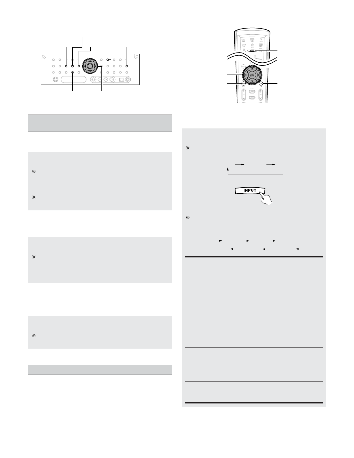
46
Basic Operation
Press the ON SCREEN button.
Each time an operation is performed, a description of
that operation appears on the display connected to AVR-
5805CI’s VIDEO MONITOR OUT terminal. Also, the
unit’s operating status can be checked during playback.
Such information as the position of the input selector
and the surround settings is output in sequence.
Checking the currently playing program
source, etc.
2 On screen display
Press the DIMMER button.
The display brightness changes in four steps (bright,
medium, dim and off).
2 Using the dimmer function
• Use this to change the brightness of the display.
Press the STATUS button.
Descriptions of the unit’s operations are also displayed
on the front panel display. In addition, the display can be
switched to check the unit’s operating status while
playing a source.
2 Front panel display
ANALOG SURROUND PARAMETER
INPUT MODE
STATUS
DIMMER
EXT. IN
CURSOR
INPUT MODE
ON SCREEN
SURROUND
PARAMETER
CURSOR
Press the INPUT MODE button.
The mode switches as shown below each time the
INPUT MODE button on the main unit is pressed:
2 Selecting the AUTO, PCM and DTS modes
AUTO PCM DTS
AUTO
EXT.IN -1EXT.IN -2 ANALOG
PCM DTS
The mode switches as shown below each time the
INPUT MODE button on the remote control unit is
pressed:
(Remote control unit)
When operating the remote control unit:
AUTO (All auto mode):
In this mode, the types of signals being input to the
digital and analog input terminals for the selected input
source are detected and the program in the AVR-
5805CI’s surround decoder is selected automatically
upon playback. This mode can be selected for all input
sources other than PHONO and TUNER.
The presence or absence of digital signals is detected,
the signals input to the digital input terminals are
identified and decoding and playback are performed
automatically in DTS, Dolby Digital or PCM (2 channel
stereo) format. If no digital signal is being input, the
analog input terminals are selected.
Use this mode to play Dolby Digital signals.
Input mode
• The AVR-5805CI has an AUTO signal detection mode that
automatically identifies the type of incoming audio signals,
but is also equipped with a manual mode that can be
switched according to the type of input audio signals.
DTS (exclusive DTS signal playback mode):
Decoding and playback are only performed when DTS
signals are being input.
PCM (exclusive PCM signal playback mode):
Decoding and playback are only performed when PCM
signals are being input.
Note that noise may be generated when using this
mode to play signals other than PCM signals.
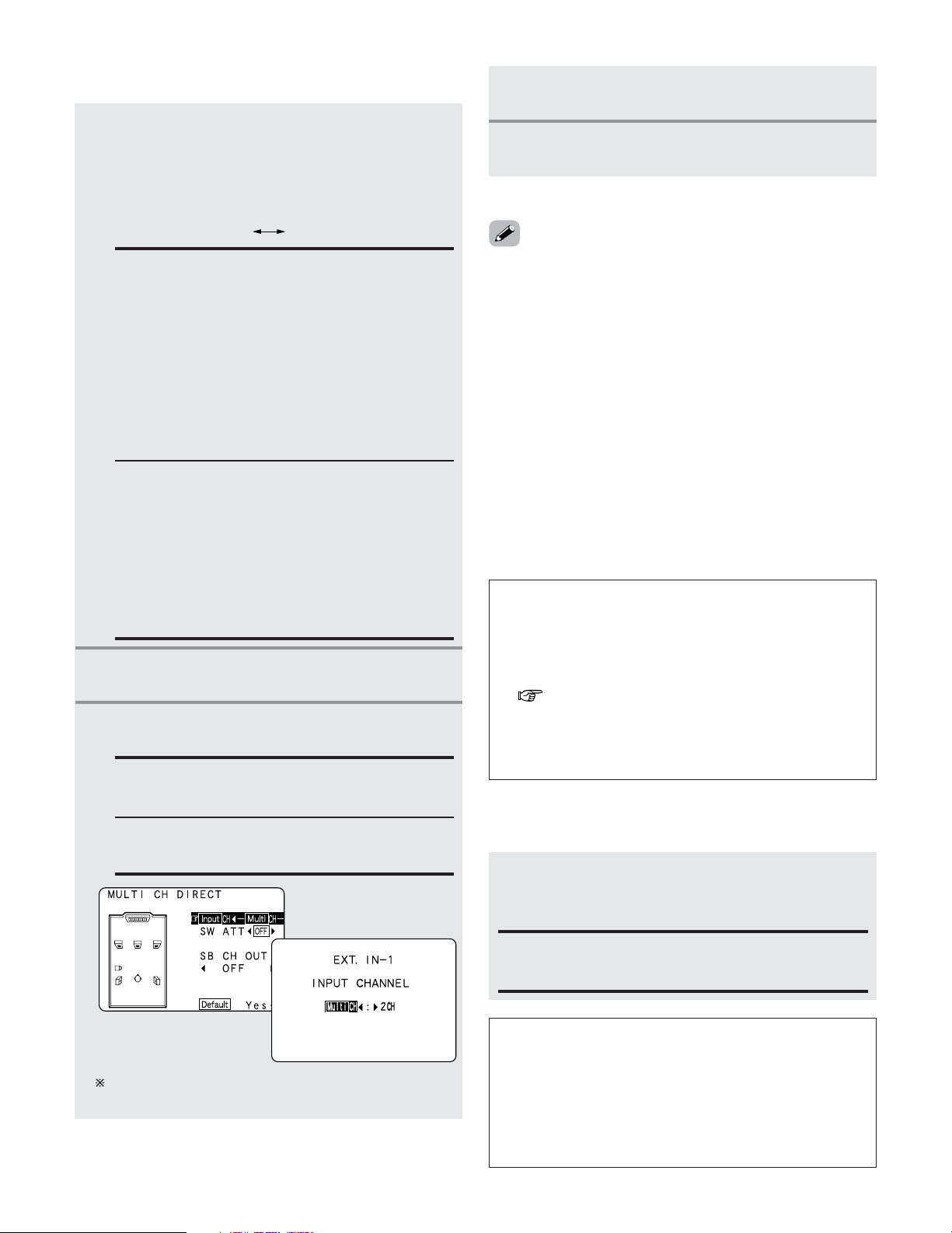
47
Basic Operation
Press the ANALOG button on the main unit or
INPUT MODE button on the remote control unit to
switch to the analog input.
2 Selecting the analog mode
ANALOG (exclusive analog audio signal playback mode):
The signals input to the analog input terminals are
decoded and played.
NOTE:
• Input mode when playing DTS sources:
Noise will be output if DTS-compatible CDs or LDs are
played in the “ANALOG” or “PCM” mode.
When playing DTS-compatible sources, be sure to
connect the source component to the digital input
terminals (OPTICAL/COAXIAL) and set the input mode to
“DTS”.
NOTE:
• When the input mode is set to EXT. IN (1 or 2), playback
in the DIRECT, STEREO, STANDARD (DOLBY/DTS
SURROUND), HOME THX CINEMA, 9CH STEREO and
DSP SIMULATION modes are only possible when “DSP”
mode is selected for the “Setting the EXT.IN Setup”
( page 105).
• In play modes other than the external input mode, the
signals connected to these terminals cannot be played. In
addition, signals cannot be output from channels not
connected to the input terminals.
EXT.IN -2EXT.IN -1
• Cancelling the external input mode:
Press the INPUT MODE or ANALOG button to switch to the
desired input mode.
• The external input mode can be set for any input source. To
watch video while listening to sound, select the input source
to which the video signal is connected, then set this mode.
• If the subwoofer output level seems too high, set the “SW
ATT” surround parameter to “ON”.
2 Selecting the EXT. IN mode
EXT. IN-1:
Once this is selected, the input signals connected to
the FRONT L, FRONT R, CENTER, SURR. L A/B
(surround left A/B), SURR. R A/B (surround right A/B)
SBL (surround back left) and SBR (surround back right)
channels of the EXT. IN terminals are output directly to
the front (left and right), center, surround A/B (left and
right A/B) and surround back (left and right) speaker
systems as well as the pre-out terminals.
In addition, the signal input to the SW (subwoofer)
terminal is output to the PRE OUT SW (subwoofer)
terminal.
EXT. IN-2:
Once this is selected, the input signals connected to
the FRONT L, FRONT R, CENTER, SURR. L (surround
left) and SURR. R (surround right) channels of the EXT.
IN terminals are output directly to the front (left and
right), center and surround (left and right) speaker
systems as well as the pre-out terminals.
In addition, the signal input to the SW (subwoofer)
terminal is output to the PRE OUT SW (subwoofer)
terminal.
Playback using the external input treminals
(EXT.IN-1 and EXT.IN-2)
• When the “ANALOG” mode is selected at “EXT.IN Setup”
at the System Setup:
The surround mode buttons are not operated.
• When the “DSP” mode is selected at “EXT.IN Setup” at
the System Setup:
The surround mode buttons are operated.
2 CH:
Select when the input source being played is a 2
channel source.
MULTI CH:
Select when the input source being played is a
multi-channel source.
Press the EXT. IN button on the main unit or
INPUT MODE button on the remote control unit
to switch the external input.
When operating the main unit:
2
Press the SURROUND PARAMETER button.
• The surround parameter menu appears.
1
3
Press the CURSOR
DD
or
HH
button to select the
parameter.
4
Press the CURSOR
FF
or
GG
button to select the
setting.
5
Press the SURROUND PARAMETER button to
complete the setting.
Press the CURSOR
FF
button to set the “Input channel”.
Press the ENTER button to return to the previous screen.
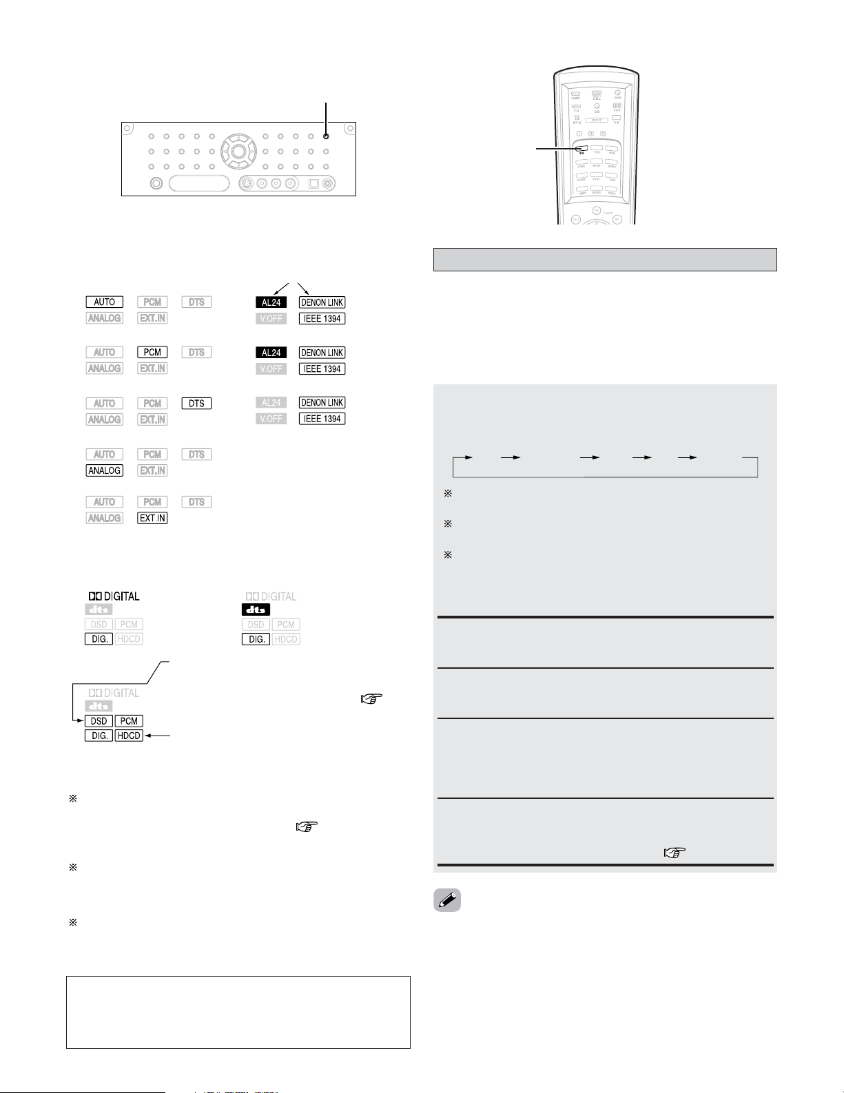
48
Basic Operation
Flat:
This the frequency response of all speakers flat.
This is suitable for multi-channel music reproduction,
from discrete music sources such as Dolby Digital 5.1,
DTS, DVD-Audio and Super Audio CD.
Room EQ function
Press the ROOM EQ button.
• The Room EQ switches as follows each time the ROOM
EQ button is pressed.
OFF Audyssey Front Flat Manual
The MultEQ XT indicator also lights red if the “Speaker
Configuration”, “Delay Time”, “Channel Level” or
“Crossover Frequency” is set manually after conducting
the Auto Setup procedure.
• The AVR-5805CI’s Auto Setup / Room EQ function offers
three correction curves: “Audyssey”, “Front”, “Flat”. The
timbre of the speakers can also be adjusted manually using
a graphic equalizer.
Details of the different correction curves are described
below.
Audyssey:
This adjusts the frequency response of all speakers to
correct the effects of room acoustics.
Front:
This adjusts the characteristics of each speaker to the
characteristics of the front speakers.
• The “Audyssey”, “Front” and “Flat” Room EQ curves can
be selected after performing the Auto Setup procedure.
Manual:
Selects the setting value that was set in the Manual EQ
Setup.
For details of the “Manual EQ Setup” ( page 118, 119).
ROOM EQ
ROOM EQ
The “Audyssey” is selected, the MultEQ XT indicator
lights green.
The “Front” or “Flat” is selected, the MultEQ XT
indicator lights red.
The “DIG.” indicator lights when digital signals are being
input properly. If the “DIG.” indicator does not light, check
whether the “Digital In Assign” ( page 104) and
connections are correct and whether the component’s
power is turned on.
AL24 processing is activated when PCM signals are played
while the surround mode is set to PURE DIRECT, DIRECT,
STEREO, MULTI CH PURE DIRECT, MULTI CH DIRECT or
MULTI CH IN.
Advanced AL24 processing is activated when PCM (2
channel) signals are played while the surround mode is set
to PURE DIRECT or DIRECT.
NOTE:
• The “DIG.” indicator will light when playing CD-ROMs
containing data other than audio signals, but no sound will
be heard.
2
Input mode indicator
• In the AUTO mode
• In the DIGITAL PCM mode
• In the DIGITAL DTS mode
• In the ANALOG mode
Depending on the input signal.
• In the EXT. IN mode
2 Input signal indicator
• DOLBY DIGITAL • DTS
• PCM
Depending on the input signal.
• The “HDCD” indicator lights when digital
signals are being input with a player that
supports HDCD playback.
Depending on the input signal.
• The “DSD” indicator lights when the DENON
LINK or IEEE1394 have been connected and
the DSD signals have been input ( page
35, 38).
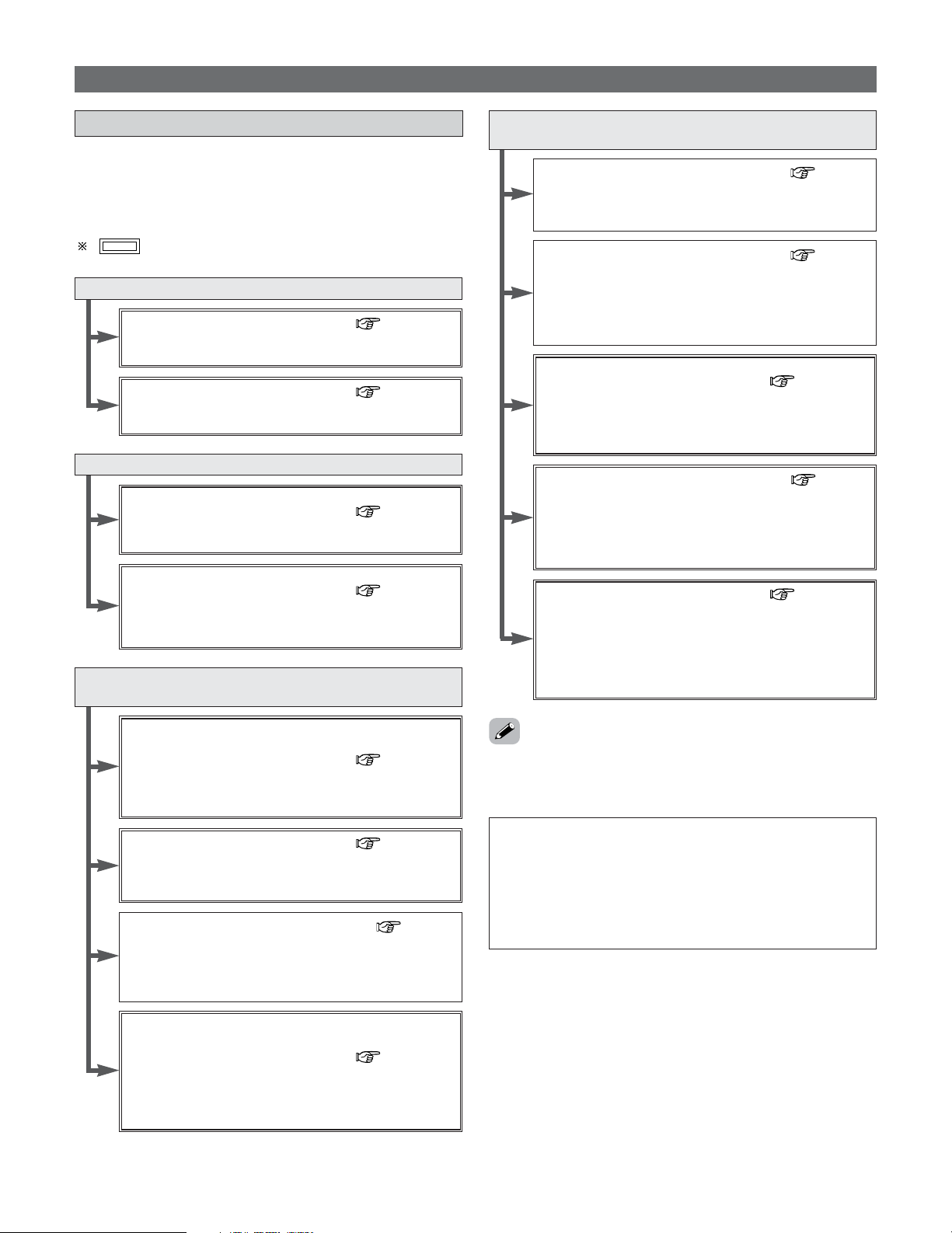
49
Basic Operation
Surround
Playing modes for different sources
• The AVR-5805CI is equipped with many surround modes.
We recommend using the surround modes as described
below in order to achieve the maximum effect for the
specific signal source.
is a 6.1 channel/7.1 channel surround mode.
Sources recorded in Dolby Digital Surround EX
THX SURROUND EX ( page 52, 53)
•Maximum performance for playing movies on the AVR-
5805CI.
DOLBY DIGITAL EX / +PLIIx
*2
( page 54, 55)
• This mode is optimized for playing sources recorded in
Dolby Digital Surround EX.
Sources recorded in DTS-ES
DTS-ES DSCRT 6.1 / MTRX 6.1 / +PLIIx
*2
( page 54, 55)
• This is the optimum mode for playing sources recorded
in DTS-ES.
ES DSCRT 6.1+THX / ES MTRX 6.1+THX
( page 52, 53)
• When playing movies, setting this mode sometimes
results in a more natural sound. Select the mode as
desired.
Dolby Digital or DTS Surround (5.1 ch sources)
2 ch sources recorded in Dolby Surround
THX Ultra2 CINEMA
*1
/ THX MUSIC MODE
*1
/
THX Games Mode
*1
/ PLIIx C+THX
( page 52, 53)
• These modes are suited for playing 5.1 channel sources
in 7.1 channels. Select the desired surround mode for the
movie and music sources.
WIDE SCREEN ( page 61, 62)
•Effective for 2 channel sources recorded in Dolby
Surround or for 7.1 channel playback with 5.1 channel
sources.
HOME THX CINEMA (THX 5.1) ( page 51)
• This mode is optimized for playing 5.1 channel movies.
• For sources recorded in Dolby Surround as well, this
mode provides the same power as with 5.1 channel
sources.
DOLBY DIGITAL / DOLBY DIGITAL+PLIIx
*2
/ DTS
SURROUND / DTS 96/24 / DTS+PL
IIx
*2
/
DTS+NEO:6
( page 54, 55)
• This mode is optimized for playing 5.1 channel or 7.1
channel music.
• For Dolby Surround recording sources, Dolby Pro Logic II
playback is conducted.
Sources recorded in stereo
Sources recorded in monaural
PURE DIRECT ( page 50)
• By suspending all circuits and processes not required,
analog input music playback can be played with optimum
quality.
DIRECT / STEREO ( page 50)
•Effective for achieving pure playback.
• If there is no need for tone control or distribution of the
low frequencies in function of the speaker configuration,
select the DIRECT mode to achieve the best sound
quality.
DENON Original Surround Modes
( page 61, 62)
• Select these for 7.1 channel playback with sources
recorded in stereo or monaural.
• The effects are different for each of the surround modes.
Select the one most suited for the source being used.
DTS NEO:6 ( page 58)
• This is a surround mode for playing 6.1 or 7.1 channel
stereo sources developed by Digital Theater Systems.
• One of two playing modes, MUSIC (for music sources) or
CINEMA (for movie sources), can be selected according
to your preferences.
DOLBY PRO LOGIC IIx
*2
( page 56, 57)
• Developed by Dolby Laboratories, this surround mode
provides 7.1 channel surround sound with conventional
stereo (2 channel) sources.
• Select CINEMA mode for movie surround soundtracks,
MUSIC for music sources, and GAME for 2 channel
game box audio sources.
NOTE:
• Surround modes indicated with an asterisk (*1) require
the use of two surround back speakers.
• Surround modes marked with an asterisk (*2) cannot be
used when the surround back speaker is set to “NONE”.
• The “+PL
IIx Cinema” mode cannot be selected when
only one surround back speaker is being used.
• Though we recommend selecting the surround mode as
described above, other surround modes can also be
selected.
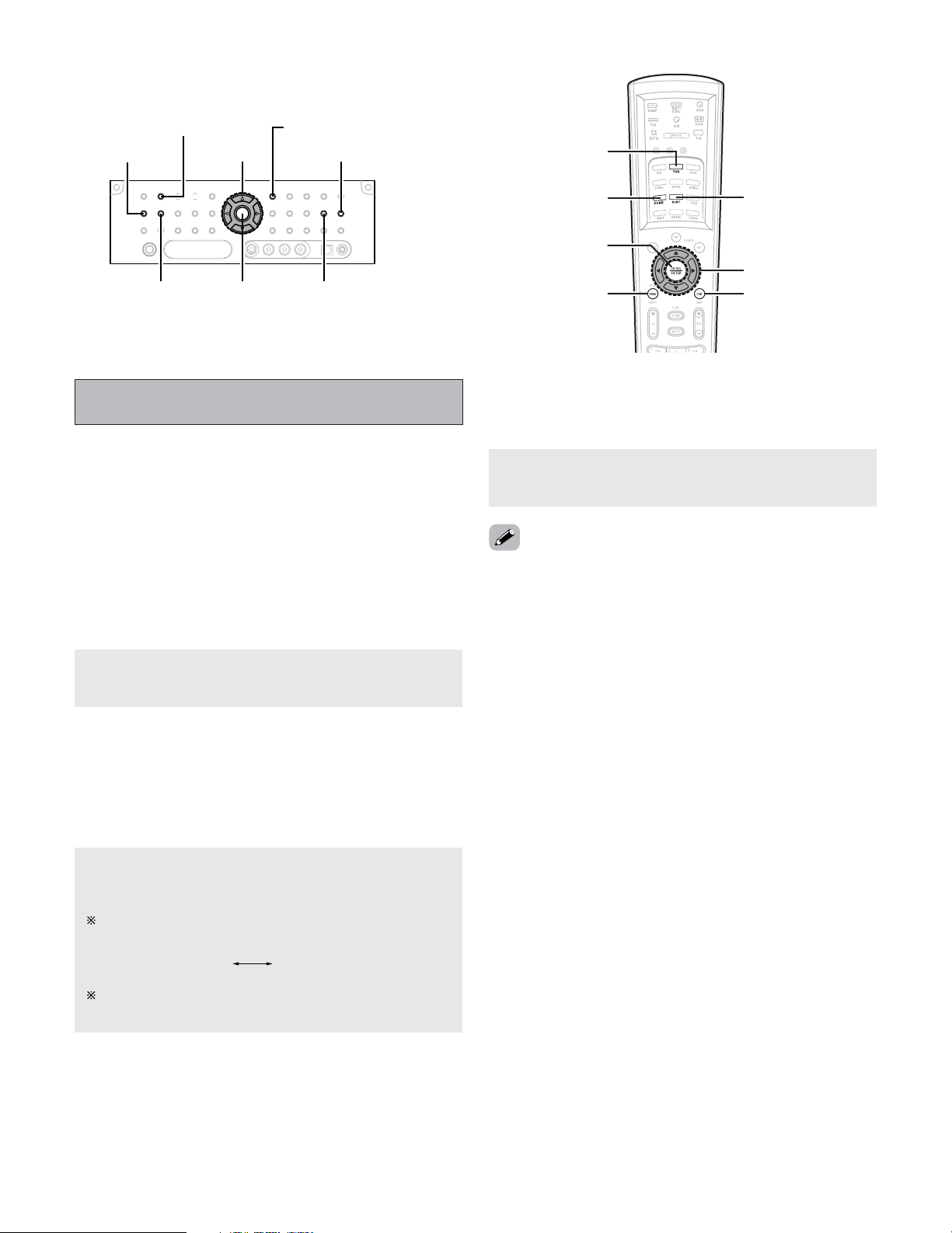
50
Basic Operation
HOME THX CINEMA
ENTER
SURROUND PARAMETER
SURROUND BACK
DIRECT/STEREO
CURSOR STATUS
PURE DIRECT
ON SCREEN
CURSOR
DIRECT/STEREO
PURE DIRECT
HOME THX
CINEMA
SURROUND
PARAMETER
ENTER
Press the DIRECT/STEREO button to select the
STEREO mode.
2 STEREO mode
Use this mode to adjust the tone and achieve the desired
sound.
• The system setup function cannot be used when the PURE
DIRECT mode is set. To use the system setup function,
cancel the PURE DIRECT mode.
• If the HDMI input terminal is selected, video outputs are
output in the PURE DIRECT mode.
• The channel level and surround parameters in the PURE
DIRECT mode are the same as in the DIRECT mode.
Playing audio sources (CDs and DVDs)
2 channel playback modes
Press the PURE DIRECT button to select the PURE
DIRECT mode.
• The AVR-5805CI is equipped with three 2 channel playback
modes exclusively for music.
• Select the mode to suit your tastes.
2
PURE DIRECT mode
This mode reproduces the sound with extremely high
quality. The audio signals do not pass through the tone
circuits, etc., and the display and surrounding circuits that
could affect the audio signals are turned “OFF”.
Press the DIRECT/STEREO button to select the
DIRECT mode.
The mode switches as shown below each time the
DIRECT/STEREO button on the main unit is pressed.
2 DIRECT mode
Use this mode to achieve good quality 2 channel sound. In
this mode, the audio signals bypass such circuits as the
tone circuit and are transmitted directly, resulting in good
quality sound.
STEREODIRECT
When press SURROUND PARAMETER:
The subwoofer output can be controlled directly.
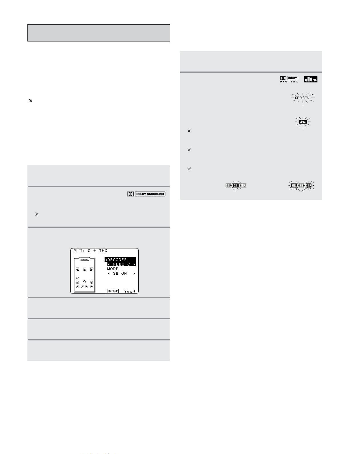
51
Basic Operation
1
Press the HOME THX CINEMA button to select
“Home THX Cinema” mode.
2
Play a program source with the
mark.
For operating instructions, refer to the manuals of the
respective components.
3
Press the SURROUND PARAMETER button.
• The surround parameter menu appears.
4
Press the CURSOR
DD
or
HH
button to select the
parameter.
5
Press the CURSOR
FF
or
GG
button to select the
setting.
6
Press the ENTER or SURROUND PARAMETER
button to complete the setting.
2 Playing sources recorded in Dolby Surround in
the Home THX Cinema Surround mode
THX Surround EX / Home THX Cinema
mode
• When the HOME THX CINEMA button is pressed, the
surround mode is set as follows according to the signal that
is played:
q THX Surround EX (THX Ultra2 Cinema)
w Home THX CINEMA (PLIIx C + THX)
e THX 5.1
r ES DSCRT 6.1 +THX, ES MTRX 6.1 + THX
When the HOME THX CINEMA mode is set when a DVD
is played, check the DVD player’s digital output setting and
change the setting to one for which Dolby Digital and DTS
bit stream signals can be output (“bit stream”, for
example).
1
Press the HOME THX CINEMA button to select
“Home THX Cinema” mode.
2
Play a program source with the ,
mark.
• The Dolby Digital indicator lights
when playing Dolby Digital
sources.
• The DTS indicator lights when
playing DTS sources.
For operating instructions, refer to
the manuals of the respective
components.
The channel status information during playback of
Dolby Digital and DTS sources can be checked
pressing the STATUS button on the main unit.
Press the SURROUND BACK button.
Lights when the Surround Back channel is on.
lights
lights
2 To play in the THX Surround EX / Home THX
Cinema Surround mode for sources recorded in
Dolby Digital or DTS
lights
Set to “1spkr” Set to “2spkrs”
lights
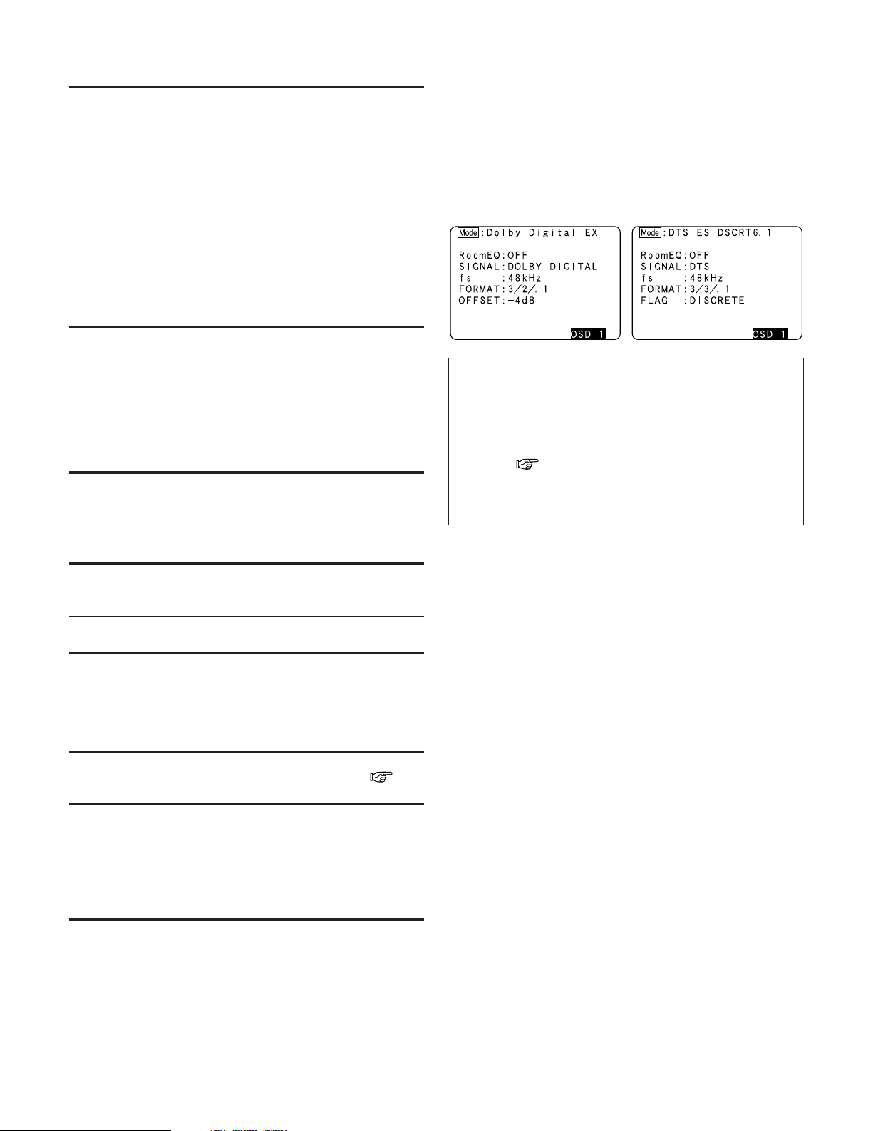
52
Basic Operation
• In addition, screen information is displayed in the following
order when the ON SCREEN button is pressed repeatedly:
OSD-1 Audio input signal
OSD-2 Monitor information
OSD-3 Input/output
OSD-4 Auto surround mode
OSD-5 USER MODE 1
OSD-6 USER MODE 2
OSD-7 USER MODE 3
OSD-8~14 Tuner preset stations
NOTE:
• OSD-2:
The monitor’s resolution is displayed when an HDMI
monitor is connected to the AVR-5805CI.
• OSD-4:
This is displayed when the auto surround mode is set to
“ON” ( page 117) and the input mode is set to
“AUTO”.
It is not displayed when the input mode is set to
“ANALOG” or “EXT. IN”.
2 Surround parameters q
MODE/SB CH OUT:
Select the surround back channel playback method or
mode.
• ON:
This is the recommended play mode for using the surround
back channel when DTS NEO:6 is selected.
• OFF:
This is the recommended play mode when Dolby Pro Logic
II is selected. The surround back channel is not played.
DECODER:
Select the decoder to be used when playing 2 channel
sources in the Home THX Cinema mode.
• PL
IIx C:
The signals are decoded in the Dolby Pro Logic
IIx Cinema
mode before undergoing THX processing.
• PL
II C:
The signals are decoded in the Dolby Pro Logic
II Cinema
mode before undergoing THX processing.
• PL:
The signals are decoded in the Dolby Pro Logic mode
before undergoing THX processing.
• NEO:6 C:
The signals are decoded in the NEO:6 Cinema mode before
undergoing THX processing.
2 Checking the input signal
• The input signal can be checked by pressing the remote
control unit’s ON SCREEN button.
SIGNAL:
Displays the type of signal (DTS, DOLBY DIGITAL, PCM,
etc.).
fs:
Displays the input signal’s sampling frequency.
FORMAT:
Displays the input signal’s number of channels.
“Number of front channels/Number of surround
channels/LFE on/off”
“SURROUND” is displayed for 2 channel signal sources
recorded in Dolby Surround.
OFFSET:
Displays the dialog normalization offset value ( page
55).
FLAG:
Displays the special identification signal recorded in the
input signal.
“MATRIX” is displayed if the input signal has undergone
matrix processing, “DISCRETE” is displayed if the input
signal has undergone discrete processing.
Not displayed when no identification signal is recorded.
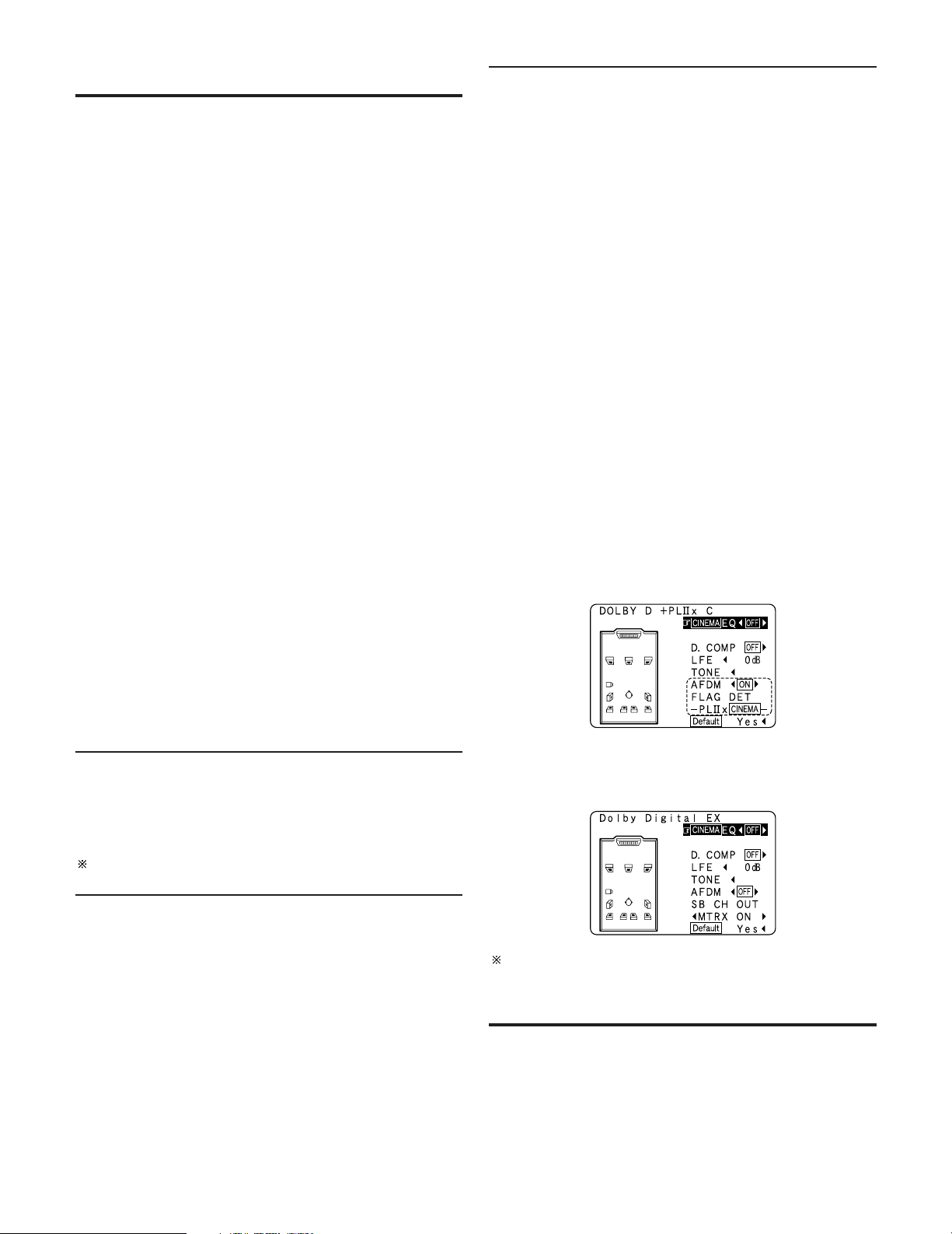
53
Basic Operation
2 Surround parameters w
MODE/SB CH OUT:
Select the surround back channel playback method or
mode.
(1) (Multi channel source)
THX Surround EX:
Dolby Digital signals are played in the “THX Surround
EX” mode.
Ultra2 Cinema:
The signals are played in the THX Ultra2 Cinema mode.
Music Mode:
The signals are played in the THX Music mode.
Games Mode:
The signals are played in the THX Games mode.
NON MTRX:
The same signals as those of the surround channels are
output from the surround back channels.
MTRX ON:
The surround channel signals undergo digital matrix
processing and are output from the surround back
channels.
SB OFF (OFF):
No signal is played from the surround back channels.
ES MTRX:
When playing DTS signals, the surround back signals
undergo digital matrix processing for playback.
ES DSCRT:
When a signal identifying the source as a discrete 6.1
channel source is included in the DTS signals, the
surround back signals included in the source are played.
PL
IIx Cinema:
Processing is performed with the Cinema mode of the
PL
IIx decoder and the surround back channel is
reproduced.
PL
IIx Music:
Processing is performed with the Music mode of the
PL
IIx decoder and the surround back channel is
reproduced.
AFDM (Auto Flag Detect Mode):
• ON:
This function only works with software on which a special
identification signal is recorded. This software is scheduled
to go on sale in the future.
This is a function for automatically playing in the 6.1
channel mode using the surround back speaker(s) if the
software is recorded in Dolby Digital EX or DTS-ES or in the
normal 5.1 channel mode without using the surround back
speaker(s) when the software is not recorded in Dolby
Digital EX or DTS-ES.
When AFDM is set to “ON” and the EX/ES flag is detected
automatically, the surround mode is fixed according to the
playing program source.
In this case, the “MODE/SB CH OUT” parameter can not
be selected on the surround parameter screen.
• OFF:
When the identification signal is detected automatically and
you would like to select the surround mode freely, set
AFDM to “OFF”.
In this case, the “MODE/SB CH OUT” parameter can be
selected on the surround parameter screen regardless of
the playing program source.
(2) (2ch source)
OFF:
Playback is conducted without using the surround back
speaker.
ON:
Playback is conducted using the surround back speaker.
This operation can be performed directly pressing the
SURROUND BACK button.
w When you would like to play back with the “Dolby Digital
EX” mode, set AFDM to “OFF” and select “MTRX ON”
with “SB CH OUT”.
Example: When playing software that has a Dolby Digital EX
flag
q When AFDM is set to “ON”, the surround mode is
automatically set to the “DOLBY DIGITAL + PL
IIx
CINEMA” mode. The surround parameter screen shown
at the below is displayed.
Some discs recorded in Dolby Digital EX do not include EX
flag. If the playing mode does not switch automatically
when the AFDM turns “ON” during playback, manually set
“SB CH OUT” to “PL
IIx Cinema” or “MTRX ON”.
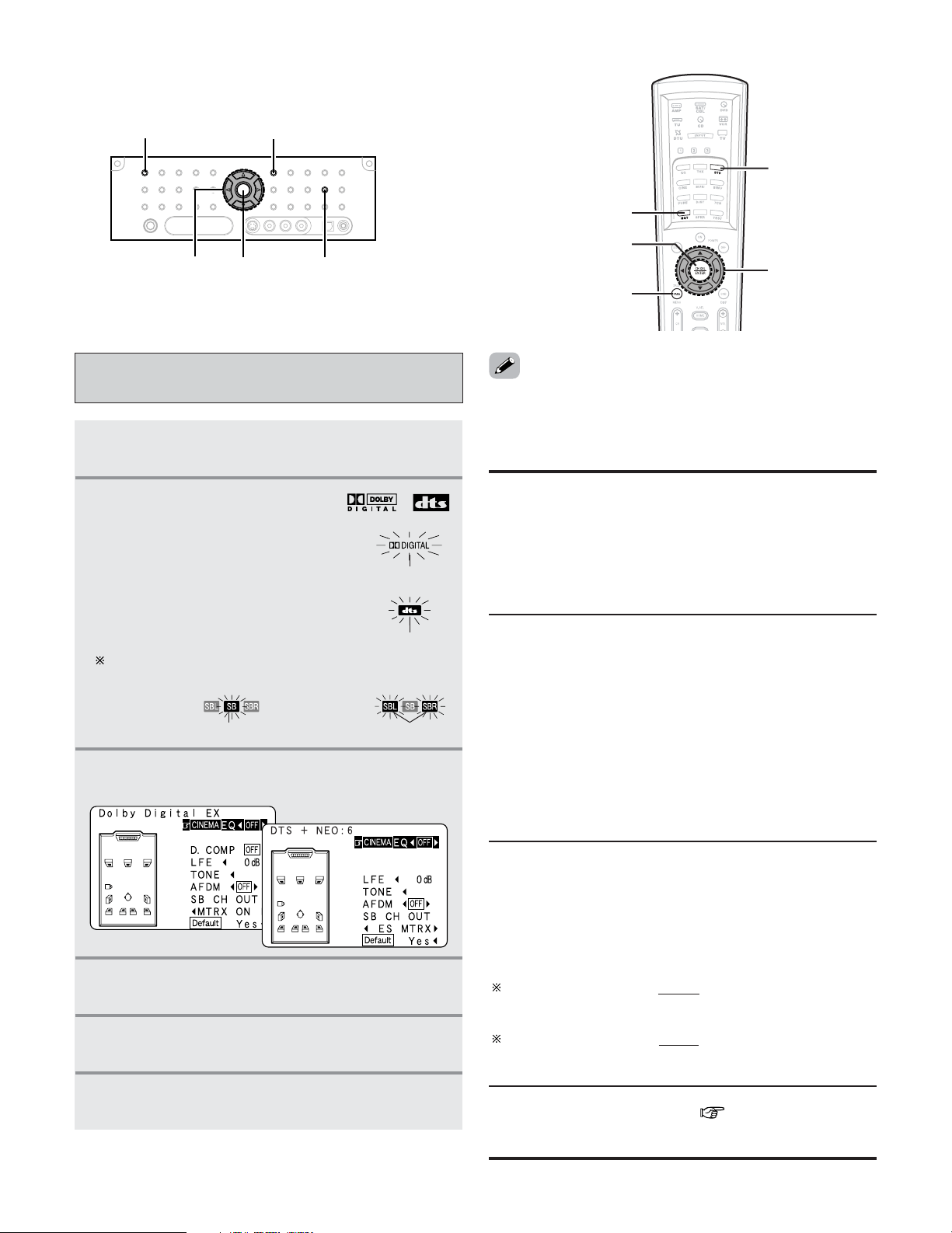
Press the SURROUND BACK button.
Lights when the Surround Back channel is on.
54
Basic Operation
Dolby Digital mode and DTS Surround
(only with digital input)
1
Press the STANDARD button to select
“STANDARD (Dolby/DTS Surround)” mode.
2
Play a program source with the ,
mark.
• The Dolby Digital indicator lights
when playing Dolby Digital
sources.
• The DTS indicator lights when
playing DTS sources.
lights
lights
3
Press the SURROUND PARAMETER button.
• The surround parameter menu appears.
5
Press the CURSOR
FF
or
GG
button to select the
setting.
6
Press the ENTER or SURROUND PARAMETER
button to complete the setting.
4
Press the CURSOR
DD
or
HH
button to select the
parameter.
SURROUND PARAMETER
STANDARD
ENTER
CURSOR
SURROUND BACK
CURSOR
NIGHT
SURROUND
PARAMETER
ENTER
STANDARD
lights
Set to “1spkr” Set to “2spkrs”
lights
LFE (Low Frequency Effect):
This sets the level of the LFE (Low Frequency Effect)
sounds included in the source when playing program
sources recorded in Dolby Digital, DTS, DVD-Audio or
Super Audio CD.
Program source and adjustment range:
1. Dolby Digital: –10 dB to 0 dB
2. DTS Surround: –10 dB to 0 dB
When DTS encoded movie
software is played, it is
recommended that the LFE LEVEL be set to 0 dB for
correct DTS playback.
When DTS encoded music
software is played, it is
recommended that the LFE LEVEL be set to –10 dB for
correct DTS playback.
TONE:
This adjusts the tone control ( page 63, 64).
This can be set individually for the separate surround mode other
than PURE DIRECT, DIRECT and Home THX Cinema mode.
• Select “Default Yes” and press the CURSOR
FF
button to
reset all the settings.
2 Surround parameters e
CINEMA EQ. (Cinema Equalizer):
The Cinema EQ function gently decreases the level of the
extreme high frequencies, compensating for overly-bright
sounding motion picture soundtracks. Select this function if
the sound from the front speakers is too bright.
This function only works in the Dolby Pro Logic
IIx, Dolby
Pro Logic, Dolby Digital, DTS Surround, DTS NEO:6 and
WIDE SCREEN modes.
D.COMP. (Dynamic Range Compression):
Motion picture soundtracks have tremendous dynamic
range (the contrast between very soft and very loud
sounds). For listening late at night, or whenever the
maximum sound level is lower than usual, the Dynamic
Range Compression allows you to hear all of the sounds in
the soundtrack (but with reduced dynamic range). (This
only works when playing program sources recorded in
Dolby Digital or DTS.) Select one of the four parameters
(“OFF”, “LOW”, “MID” (middle) or “HI” (high)). Set to
OFF for normal listening.
This parameter is displayed only when playing compatible
sources in DTS mode.
55
Basic Operation
2 Dialogue Normalization
Dialogue Normalization (Dial Norm) is a feature of Dolby
Digital, which is used to keep the programs at the same
average listening level so the user does not have to change
the volume control between Dolby Digital programs. When
playing back software which has been encoded in Dolby
Digital, sometimes you may see a brief message in the
front panel display which will read “Dial Norm X dB” (X
being a numeric value). The display is showing how the
program level relates with THX calibration level. If you want
to play the program at calibrated theatrical levels, you may
wish to adjust the volume. For example, if you see the
following message: “Dial Norm + 4 dB” in the front panel
display, to keep the overall output level at THX calibrated
loudness, just turn down the volume control by 4 dB.
However, unlike a movie theater where the playback
loudness is preset, you can choose your preferred volume
setting for best enjoyment.
Display
Offset -4dB
Dial.Norm
When listening at night or at lower volumes, the night mode
improves listenability.
Press the NIGHT button on the remote control unit
to enter the night mode.
Night mode
• Canceling night mode:
Press the NIGHT button again.
• The night mode only works when playing program sources
recorded in Dolby Digital.
• When the night mode is set to “ON”, the “D.COMP”
surround parameter can not be selected.
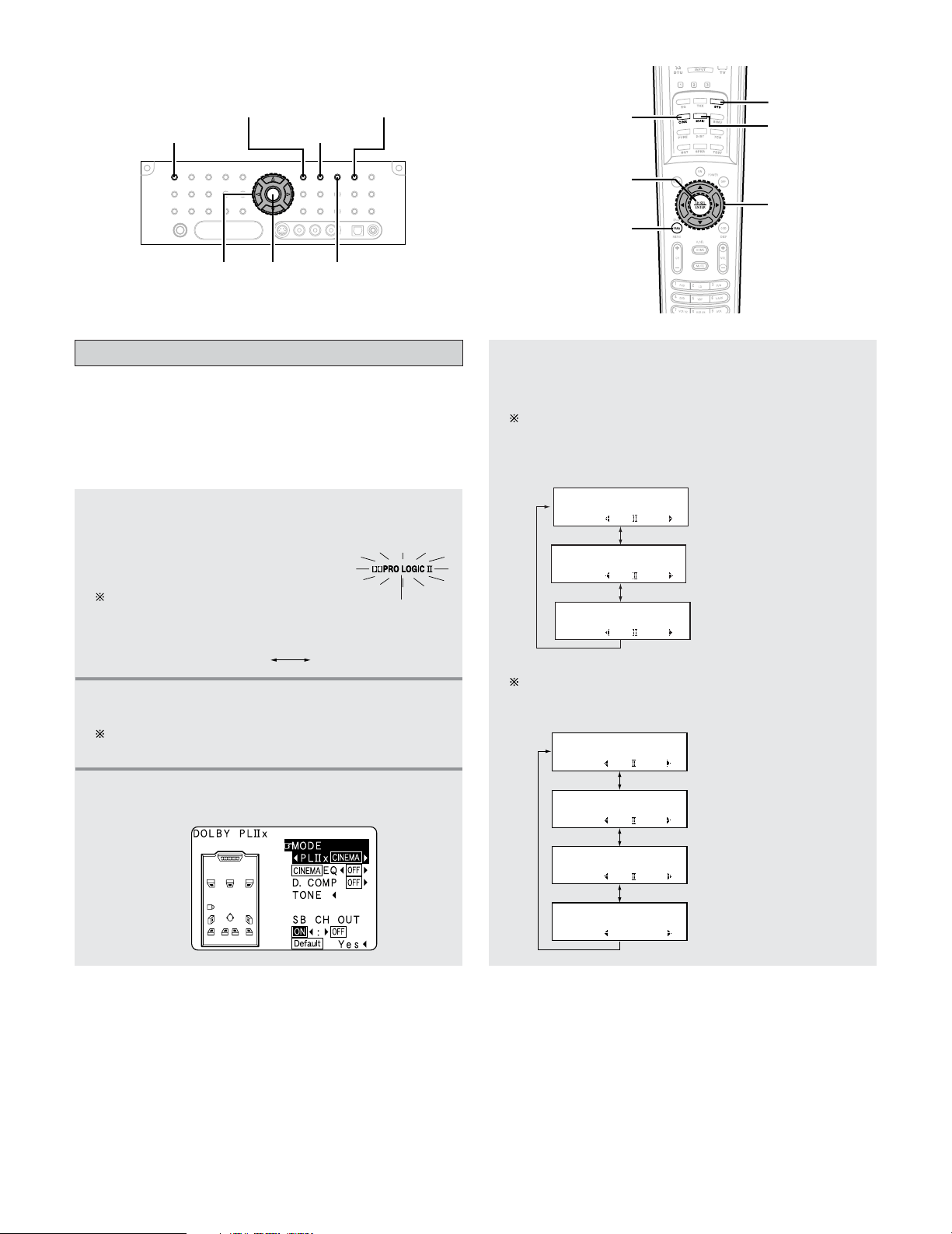
56
Basic Operation
Dolby Pro Logic
II
x (Pro Logic
II
) mode
•To play in the PLIIx mode, set “Sp.Back” at the Speaker
Configuration setting to “1spkr” or “2spkrs”.
•To play in the PL
IIx mode, set “Surround Back” at the Power
Amp Assign setting.
• This mode is optimal for playing program sources recorded
in Dolby Surround.
1
Press the STANDARD button to select “Dolby
Pro Logic IIx” mode.
• The Dolby Pro Logic indicator
lights.
The mode switches as shown
below each time the STANDARD
button is pressed.
lights
DTS NEO:6DOLBY PLIIx
3
Press the SURROUND PARAMETER button.
• The surround parameter menu appears.
2
Play a program source.
For operating instructions, refer to the manuals of the
respective components.
4
Press the CURSOR
FF
or
GG
button to select the
play mode.
When the “SB CH OUT” parameter is set to “ON”.
(Set “SP.Back” at the System Setup to “1spkr” or
“2spkrs”).
SURROUND PARAMETER
STANDARD
ENTER MUSIC
CINEMA
GAME
CURSOR
CURSOR
MUSIC
SURROUND
PARAMETER
ENTER
CINEMA
STANDARD
(Pro Logic II Cinema mode)
(Pro Logic
II Music mode)
(Pro Logic II Game mode)
When the “SB CH OUT” parameter is set to “OFF”.
(Set “SP.Back” at the System Setup to “None”).
Display
MODE: PL G
*Surr Parameter
MODE: PL C
*Surr Parameter
MODE: PL M
*Surr Parameter
*Surr Parameter
MODE: DOLBY PL
(Dolby Pro Logic mode)
MODE: PL x C
*Surr Parameter
MODE: PL x M
*Surr Parameter
MODE: PL x G
*Surr Parameter
(Pro Logic IIx Cinema mode)
(Pro Logic
IIx Music mode)
(Pro Logic
IIx Game mode)
Display
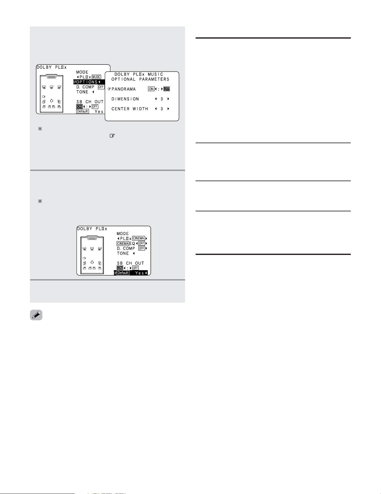
57
Basic Operation
2 Surround parameters r
Pro Logic IIx and Pro Logic II Mode:
Select one of the modes (“Cinema”, “Music”, “Pro Logic”
or “Game”).
The Cinema mode is for use with stereo television shows
and all programs encoded in Dolby Surround.
The Music mode is recommended for stereo music and
surround-encoded stereo music sources.
The Pro Logic mode emulates Dolby Laboratories’ original
Dolby Pro Logic surround decoding, and may provide better
results with older, legacy surround-encoded program
material.
The Game mode is optimized for computer and/or
dedicated game box consoles, that feature stereo analog or
digital outputs. It can only be used with 2 channel stereo
sources.
DIMENSION:
This control gradually adjust the soundfield either towards
the front or towards the rear.
The control can be set in 7 steps from 0 to 6.
CENTER WIDTH:
This control adjust the center image so it may be heard only
from the center speaker; only from the left/right speakers
as a phantom image; or from all three front speakers to
varying degrees.
The control can be set in 8 steps from 0 to 7.
PANORAMA:
This mode extends the front stereo image to include the
surround speakers for an exciting “wraparound” effect
with side wall imaging.
Select “OFF” or “ON”.
When set with the on screen display while in the
MUSIC mode, set the “ ” mark to “OPTIONS
0
”
pressing the CURSOR
DD
or
HH
button, then press the
CURSOR
FF
button.
Press the ENTER button to return to the previous
screen.
6
Press the CURSOR
FF
or
GG
button to adjust the
parameters setting.
Default setting:
Press the CURSOR
FF
button to select “Default
Yes
0
”, then parameters set to default setting.
7
Press the ENTER or SURROUND PARAMETER
button to complete the setting.
5
Press the CURSOR
DD
or
HH
button to select the
various surround parameters.
Example: DOLBY PLIIx Music mode screen
• The Dolby Pro Logic IIx (Pro Logic II) Cinema, Music or
Game mode can be chosen directly by pressing the CINEMA,
MUSIC or GAME button during playback in the Dolby Pro
Logic
IIx (Pro Logic II) mode.
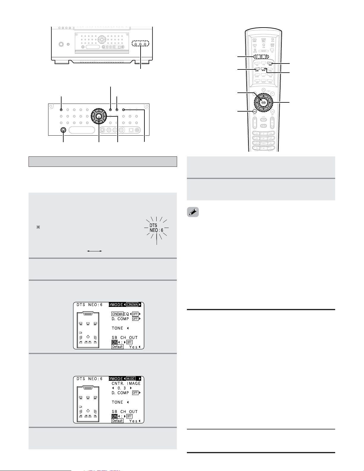
58
Basic Operation
7
Press the ENTER or SURROUND PARAMETER
button to complete the setting.
6
Press the CURSOR
FF
or
GG
button to adjust the
parameters setting.
• Select “Default Yes” and press CURSOR
FF
button to reset all
the settings.
• When playing PCM digital signals or analog signals in the
DOLBY PRO LOGIC
II, DOLBY PRO LOGIC IIx, DTS NEO:6
modes and the input signal switches to a digital signal
encoded in Dolby Digital, the Dolby Surround mode switches
automatically. When the input signal switches to a DTS
signal, the mode automatically switches to DTS Surround.
•The DTS NEO:6 Cinema or Music mode can be chosen
directly by pressing the CINEMA or MUSIC button on the
Remote control unit during playback in the DTS NEO:6 mode.
DTS NEO:6 mode
• Surround playback can be performed for the analog input and
digital input 2 channel signals.
1
Press the STANDARD button to select “DTS
NEO:6” mode.
• The DTS NEO:6 indicator lights.
The mode switches as shown
below each time the STANDARD
button is pressed.
lights
DTS NEO:6DOLBY PLIIx
2
Play a program source.
3
Press the SURROUND PARAMETER button.
• The surround parameter menu appears.
4
Press the CURSOR
FF
or
GG
button to select the
play mode.
SURROUND PARAMETER
CINEMA
STANDARD
ENTERPHONES
CURSOR
MUSIC
CURSOR
SURROUND
PARAMETER
ENTER
STANDARD
MUSIC
USER MODE
CINEMA
5
Press the CURSOR
DD
or
HH
button to select the
various surround parameters.
2 Surround parameters t
DTS NEO:6 Mode:
• Cinema:
This mode is optimum for playing movies. Decoding is
performed with emphasis on separation performance to
achieve the same atmosphere with 2 channel sources as
with 6.1 channel sources.
This mode is effective for playing sources recorded in
conventional surround formats as well, because the in-phase
component is assigned mainly to the center channel (C) and
the reversed phase component to the surround (SL, SR and
SB channels).
• Music:
This mode is suited mainly for playing music. The front
channel (FL and FR) signals bypass the decoder and are
played directly so there is no loss of sound quality, and the
effect of the surround signals output from the center (C) and
surround (SL, SR and SB) channels add a natural sense of
expansion to the sound field.
CENTER IMAGE (0.0 to 1.0: default 0.3):
The center image parameter for adjusting the expansion of the
center channel in the DTS NEO:6 MUSIC mode has been added.
USER MODE
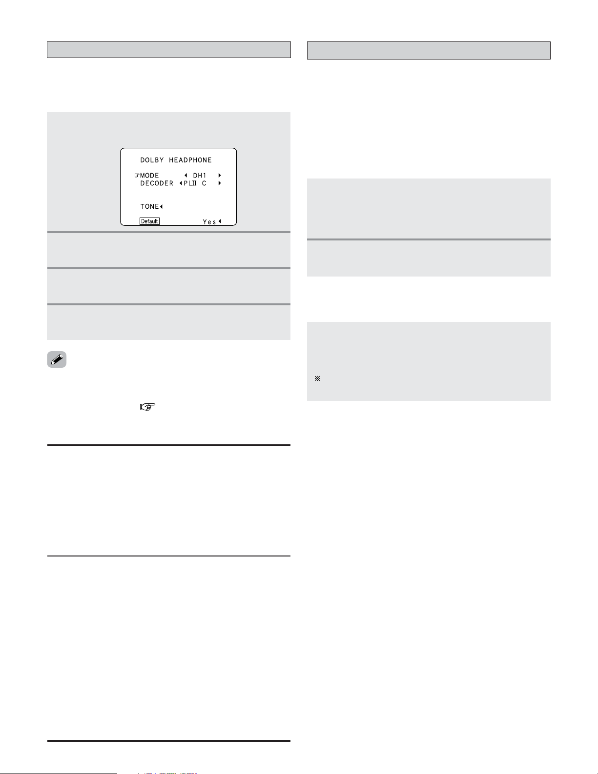
59
Basic Operation
2 Parameters
MODE:
• DH1:
Reference room (small room with weak reverberations).
• DH2:
Live room (room with a bit stronger reverberations than DH1).
• DH3:
Large room (larger room than DH1, offers a sense of
distance and sound diffusion effects).
• BYPASS:
Stereo sound.
DECODER:
Select this when playing analog, PCM or other 2 channel
sources.
The signals are converted into multichannel signals using
the decoders shown below and played in the Dolby
Headphone mode.
• PL
II C:
Dolby Pro Logic
II Cinema mode.
• PL
II M
Dolby Pro Logic
II Music mode.
• NEO:6 C:
DTS NEO:6 Cinema mode.
• NEO:6 M:
DTS NEO:6 Music mode.
• OFF:
The signals are played in the Dolby Headphone mode as
such (2 channels).
The Dolby Headphone
• The Dolby Headphone mode is set when headphones are
connected to the PHONES jack while in the STANDARD
(DOLBY/DTS SURROUND) mode.
1
Press the SURROUND PARAMETER button.
• The surround parameter menu appears.
2
Press the CURSOR
DD
or
HH
button to select the
parameter.
3
Press the CURSOR
FF
or
GG
button to select the
setting.
4
Press the ENTER or SURROUND PARAMETER
button to complete the setting.
USER MODE function
• The AVR-5805CI is equipped with a function for storing the
selected input source, the auto surround mode and input
mode in the memory and selecting these settings when you
want to use them.
• Three patterns of settings can be stored in the memory
pressing the USER MODE buttons.
1
The following are stored in the memory:
q Currently set input source
w Currently set auto surround mode
e Currently set input mode
2 Storing the settings in the memory
2
Press and hold the USER MODE button until
the “ USER MODE” indicator lights.
Press the USER MODE button at which the settings
you want to call out are stored.
• The user mode indicator lights.
The indicator turns off if you perform any operations that
change the settings stored at the USER MODE buttons.
2 Calling the settings out
• When RECOUT mode is set to “SOURCE”, with this
amplifier signals encoded in the Dolby Headphone mode can
be output from the recording output terminals and recorded
on another recorder ( page 101).
60
Basic Operation
WIDE SCREEN
DENON original surround modes
• The AVR-5805CI is equipped with a high performance DSP (Digital Signal Processor) which uses digital signal processing to
synthetically recreate the sound field. One of ten preset surround modes can be selected according to the program source and
the parameters can be adjusted according to the conditions in the listening room to achieve a more realistic, powerful sound.
Surround modes and their features
2 Personal Memory Plus
This set is equipped with a personal memorize function that automatically memorizes the surround modes and input modes
selected for the input different sources. When the input source is switched, the modes set for that source last time it was
used are automatically recalled.
The surround parameters, tone control settings and playback level balance for the different output channels are memorized for
each surround mode.
1
2
3
4
5
6
7
9
SUPER
STADIUM
ROCK ARENA
JAZZ CLUB
CLASSIC
CONCERT
MONO MOVIE
(NOTE)
VIDEO GAME
VIRTUAL
Select this when watching baseball or soccer programs to achieve a sound as if you were actually at
the stadium. This mode provides the longest reverberation signals.
Use this mode to achieve the feeling of a live concert in an arena with reflected sounds coming from
all directions.
This mode creates the sound field of a live house with a low ceiling and hard walls. This mode gives
jazz a very vivid realism.
Select this for the sound of a concert hall rich in reverberations.
Select this when watching monaural movies for a greater sense of expansion.
Use this to enjoy video game sources.
Select this to achieve an atmosphere like that of a movie theater with a large screen. In this mode,
all signal sources are played in the 7.1 channel mode, including Dolby Surround and Dolby Digital 5.1
channel sources. Effects simulating the multi surround speakers of movie theaters are added to the
surround channels.
Select this mode to enjoy a virtual sound field, produced from the front 2 channel speakers.
This mode can be selected when surround playback is being performed in ZONE2.
8
MATRIX
Select this to emphasize the sense of expansion for music sources recorded in stereo. Signals
consisting of the difference component of the input signals (the component that provides the sense
of expansion) processed for delay are output from the surround channel.
Depending on the program source being played, the effect may not be very noticeable.
In this case, try other surround modes, without worrying about their names, to create a sound field suited to your tastes.
NOTE: When playing sources recorded in monaural, the sound will be one-sided if signals are only input to one channel (left
or right), so input signals to both channels. If you have a source component with only one audio output (monophonic
camcorder, etc.) obtain a “Y” adaptor cable to split the mono output to two outputs, and connect to the L and R inputs.
10
9CH STEREO
The front left channel signals are output to the surround and surround back signal left channels, the
front right channel signals are output to the surround and surround back signal right channels, and the
in-phase component of the left and right channels is output to the center channel. Use this mode to
enjoy stereo sound.
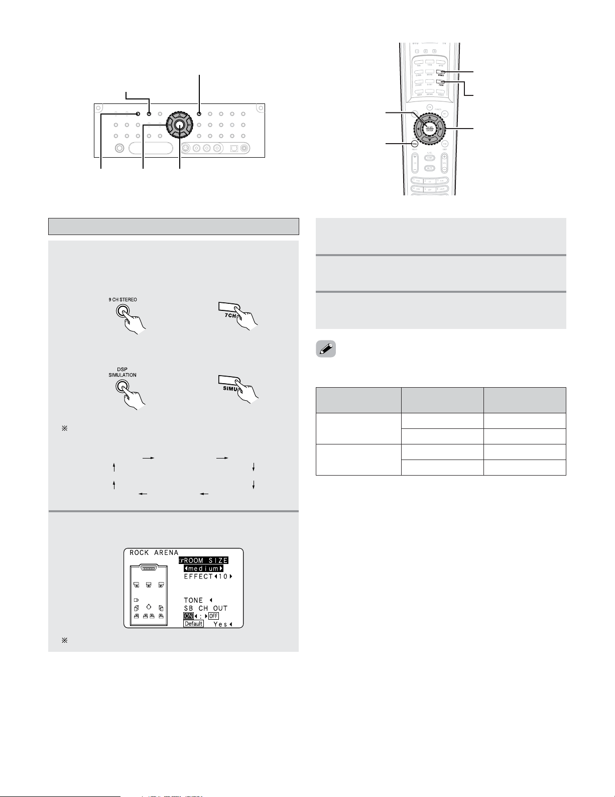
SURROUND BACK
SPEAKER
SURROUND
SPEAKER SETTING
DISPLAY
61
Basic Operation
SURROUND
PARAMETER
DSP SIMULATION
ENTER
CURSOR
9CH
STEREO
DSP SIMULATION
9CH STEREO
CURSOR
SURROUND
PARAMETER
ENTER
DSP surround simulation
1
Select the surround mode for each input
channel.
Example: 9CH STEREO mode
The surround mode switches in the following order
each time the DSP SIMULATION button is pressed:
(Remote control unit)
Example: DSP surround simulation mode
WIDE SCREEN
JAZZ CLUB
SUPER STADIUM
ROCK ARENA
MATRIX
VIDEO GAME
CLASSIC CONCERT
MONO MOVIE
2
Press the SURROUND PARAMETER button.
• The surround parameter menu appears.
3
Press the CURSOR
DD
or
HH
button to select the
various surround parameters.
5
Press the ENTER or SURROUND PARAMETER
button to complete the setting.
4
Press the CURSOR
FF
or
GG
button to adjust the
parameters setting.
ON
OFF
A + B
A + B
The screen for the selected surround mode appears.
• The “9CH STEREO” display changes as shown below
according to the surround back speaker setting.
• Select “Default Yes” and press the CURSOR
FF
button to
reset all the settings.
(Main unit)
(Remote control unit)(Main unit)
9CH STEREO
A or B 7CH STEREO
7CH STEREO
A or B 5CH STEREO
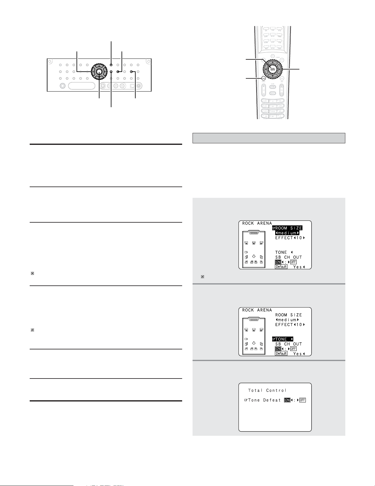
62
Basic Operation
SURROUND PARAMETER
SURROUND
BACK
TONE DEFEAT
TONE CONTROL
CURSOR
ENTER
CURSOR
SURROUND
PARAMETER
ENTER
ROOM SIZE:
This sets the size of the sound field.
There are five settings: “small”, “med.s” (medium-small),
“medium”, “med.l” (medium-large) and “large”. “small”
recreates a small sound field, “large” a large sound field.
The “ROOM SIZE” expresses the expansion effect for the
different surround modes in terms of the size of the sound
field, not the actual size of the listening room.
2 Surround parameters y
EFFECT:
This parameter turns the effect signals with multi surround
mode speaker effects on and off in the WIDE SCREEN
mode. When this parameter is turned off, the SBL and SBR
channel signals are equivalent to the SL and SR channels,
respectively.
LEVEL:
This parameter sets the strength of the effect signals in the
WIDE SCREEN mode. It can be set in 15 steps, from “1”
to “15”. Set this to a low level if the positioning or phase
of the surround signals sounds unnatural.
SB CH OUT:
• ON:
Playback is conducted using the surround back speaker.
• OFF:
Playback is conducted without using the surround back
speaker.
This operation can be performed directly pressing the
SURROUND BACK button on the main unit’s panel.
DELAY TIME:
In the matrix mode only, the delay time can be set within
the range of 0 to 300 ms.
EFFECT LEVEL:
This sets the strength of the surround effect.
The level can be set in 15 steps from 1 to 15. Lower the
level if the sound seems distorted.
Tone control setting
• Use the tone control setting to adjust the bass and treble as
desired.
• The tone control function will not work in the PURE DIRECT,
DIRECT or Home THX Cinema mode.
2
Adjusting the tone from the remote control unit
1
Press the SURROUND PARAMETER button.
• The surround parameter menu appears.
2
Press the CURSOR
DD
or
HH
button to select
“TONE”.
The screen selected surround mode appears.
3
Press the CURSOR
FF
button.
• Switch to the “Total Control” screen.
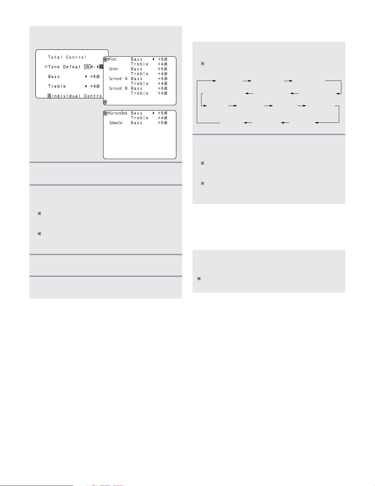
63
Basic Operation
4
Press the CURSOR
GG
button to select “Tone
Defeat OFF”.
5
Press the CURSOR
DD
or
HH
button to select
“Bass” or “Treble”.
6
Press the CURSOR
FF
or
GG
button to set the
level.
To increase the bass or treble:
The bass or treble sound can be increased to up to +6
dB in steps of 1 dB.
To decrease the bass or treble:
The bass or treble sound can be decreased up to –6 dB
in steps of 1 dB.
8
Press the ENTER or SURROUND PARAMETER
button to complete the setting.
7
Press the ENTER button.
• The surround parameter menu reappears.
2 Adjusting the tone from the main unit
1
Press the TONE CONTROL button.
The tone switches as follows each time the button is
pressed.
BASS (ALL)
F-TREBLE (front)
TREBLE (ALL) F-BASS (front)
C-BASS (center)C-TREBLE (center)
S B-TREBLE
(surround B)
SA-TREBLE
(surround A)
SA-BASS
(surround A)
S B-BASS
(surround B)
SW-BASS
(subwoofer)
SB-BASS
(surround back)
SB-TREBLE
(surround back)
2
Press the CURSOR
FF
or
GG
button to set the
level.
To increase the bass or treble:
The bass or treble sound can be increased to up to +6
dB in steps of 1 dB.
To decrease the bass or treble:
The bass or treble sound can be decreased up to –6 dB
in steps of 1 dB.
2 Tone defeat mode
• If you do not want the bass and treble to be adjusted, turn
on the tone defeat mode.
Press the TONE DEFEAT button to turn on the
“Tone Defeat” mode.
The signals do not pass through the bass and treble
adjustment circuits, providing higher quality sound.
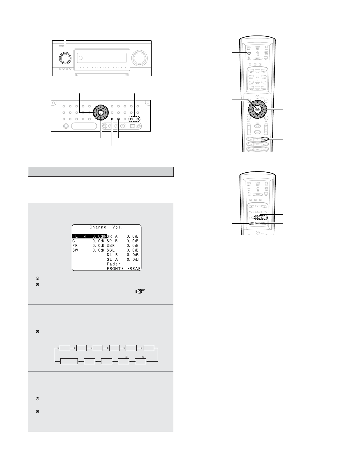
64
Basic Operation
FUNCTION
MODE
TUNING
BAND
BAND
TUNING
MODE
CURSOR
CH SEL/ENTER
•You can adjust the channel level either according to the
playback sources or to suit your tastes, as described below.
1
Press the CH SEL/ENTER button.
• The “Channel Vol.” screen appears.
2
Press the CURSOR
DD
,
HH
or CH SEL/ENTER
button to select the speaker.
The channel switches as shown below each time the
CH SEL/ENTER button is pressed.
Channels which is not used are not displayed.
When the surround back speaker setting is set to
“1spkr” for “Speaker Configuration” ( page 140,
141), this is set to “SB”.
FADER
SRA
SBLSLBSLA
SRB
SBR
FL C FR SW
3
Press the CURSOR
FF
or
GG
button to adjust the
level.
The adjustment range for the different channels is
+12.0 dB to –12.0 dB in step of 0.5 dB.
The sound from the subwoofer can be completely cut
by lowering the SW (subwoofer) setting one additional
from –12.0 dB (setting it to “OFF”).
Channel Level
CURSOR
CH SEL/
ENTER
TUNER
TU
(AMP mode)
(TUNER mode)
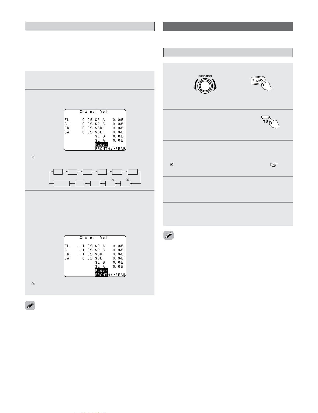
65
Basic Operation
Fader function
• This function makes it possible to lower the volume of the
front channels (FL, C and FR) or the rear channels (SL, SR,
SBL and SBR) together. Use it for example to adjust the
balance of the sound from each position when multi-channel
music sources are played.
1
Press the CH SEL/ENTER button.
• The “Channel Vol.” screen appears.
2
Press the CURSOR
DD
,
HH
or CH SEL/ENTER
button then select “Fader”.
FADER
SRA
SBLSLBSLA
SRB
SBR
FL C FR SW
The channel switches in the order shown below each
time the CH SEL/ENTER button is pressed.
3
Press the CURSOR
FF
button to reduce the
volume of the front channels, the
CURSOR
GG
button to reduce the volume of the rear
channels.
Example: When “FRONT” is selected
The fader function does not affect the subwoofer
channel.
• The channel whose channel level is adjusted lowest can be
faded to –12.0 dB using the fader function.
• If the channel levels are adjusted separately after adjusting
the fader, the fader adjustment values are cleared, so adjust
the fader again.
Listening to the Radio
• Check that the remote control unit is set to AMP or TUNER.
Auto tuning
1
Set the input source to “TUNER”.
2
Press the TU (TUNER)
button to select the TUNER
mode.
(Main unit)
(Remote control unit
in the AMP mode)
3
Watching the display, press the BAND button
to select the desired band (AM, FM or XM).
When listening to the XM satellite Radio ( page
71).
4
Press the MODE button to set the auto tuning
mode.
• The “AUTO” indicator lights.
5
Press the TUNING button.
• Automatic searching begins, then stops when a
station is tuned in.
• If tuning does not stop at the desired station, use to the
“Manual tuning” operation.
• When in the auto tuning mode on the FM band, the
“STEREO” indicator lights on the display when a stereo
broadcast is tuned in. At open frequencies, the noise is
muted and the “TUNED” and “STEREO” indicators turn off.
(Remote control unit)
66
Basic Operation
Manual tuning
1
Set the input source to “TUNER”.
2
Press the TU (TUNER)
button to select the TUNER
mode.
3
Watching the display, press the BAND button
to select the desired band (AM, FM or XM).
When listening to the XM satellite Radio ( page
71).
FUNCTION TUNING PRESET
MEMORY
ON SCREEN
(AMP mode)
CHANNEL
NUMBER
SHIFT
BAND
MODE
MEMORY
BLOCK
RDS SEARCH
TUNING
TUNER
(AMP mode)
TU
(Main unit)
(Remote control unit)
4
Press the MODE button to set the manual tuning
mode.
Check that the display’s “AUTO” indicator turns off.
5
Press the TUNING button to tune in the desired
station.
The frequency changes continuously when the button
is held in.
• When the manual tuning mode is set, FM stereo broadcasts
are received in monaural and the “STEREO” indicator turns
off.
Preset memory
1
Use the “Auto tuning” or “Manual tuning”
operation to tune in the station to be preset in
the memory.
2
Press the TU (TUNER)
button to select the TUNER
mode.
3
Press the MEMORY button.
4
Press the MEMORY BLOCK (A to G) button.
The memory block can also be selected by pressing
the SHIFT button.
5
Press the CHANNEL button or NUMBER (1 to
8) button to select the desired preset channel.
6
Press the MEMORY button again.
• Store the station in the preset memory.
•To preset other channels, repeat steps 2 to 5.
A total of 56 broadcast stations can be preset — 8 stations
(channels 1 to 8) in each of blocks A to G.
(Remote control unit)
(Remote control unit
in the AMP mode)
BAND
TUNINGMEMORY
MODE
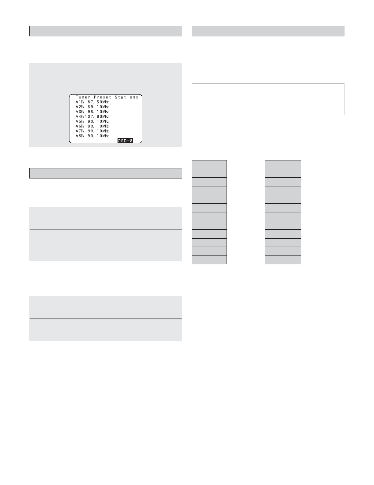
67
Basic Operation
Checking the preset stations
• The preset (broadcast) stations can be checked on the on
screen display.
Press the ON SCREEN button (in the AMP mode)
repeatedly until the “Tuner Preset Stations” screen
appears on the on screen display.
Recalling preset stations
2 Recalling preset stations from the remote
control unit
1
Press the MEMORY BLOCK (A to G) button to
select the memory block (A to G).
2
Watching the display, press the CHANNEL
button or NUMBER (1 to 8) button to select the
desired preset channel.
2 Recalling preset stations from the main unit’s
panel
1
Press the TUNING PRESET button.
2
Turn the FUNCTION knob and select the
desired preset channel.
RDS (Radio Data System)
• RDS (works only on the FM band) is a broadcasting service
which allows station to send additional information along
with the regular radio program signal.
• The following three types of RDS information can be
received on this unit:
2
Program Type (PTY)
• PTY identifies the type of RDS program.
• The program types and their displays are as follows:
News
Information
Sports
Talk
Rock
Classic rock
Adult hits
Soft rock
NEWS
INFORM
SPORTS
TALK
ROCK
CLS ROCK
ADLT HIT
SOFT RCK
Top 40
Country
Oldies
Soft
TOP 40
COUNTRY
OLDIES
SOFT
Nostalgia
Jazz
Classical
NOSTALGA
JAZZ
CLASSICL
R & B
R & B
Soft R&B
Language
Religious music
Religious talk
Personality
Public
SOFT R&B
LANGUAGE
REL MUSC
REL TALK
PERSNLTY
PUBLIC
College
Weather
COLLEGE
WEATHER
2 Traffic Program (TP)
• TP identifies programs that carry traffic announcements.
• This allows you to easily find out the latest traffic conditions
in your area before you leaving home.
2
Radio Text (RT)
•RT allows the RDS station to send text messages that
appear on the display.
NOTE:
• The operations described below pressing the RDS SEARCH
button will not function in areas in which there are no RDS
broadcasts.
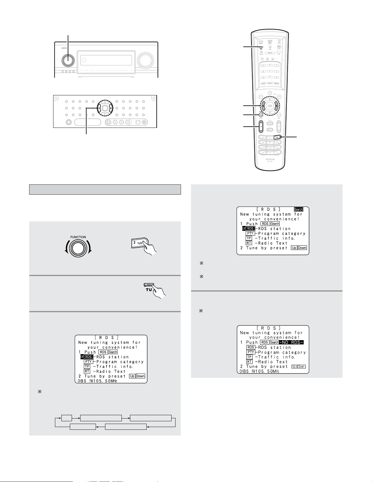
68
Basic Operation
RDS search
1
Set the input source to “TUNER”.
3
Press the RDS SEARCH button until “RDS
SEARCH” appears on the display.
• Use this function to automatically tune to FM stations that
provide RDS service.
RDS SEARCHFM PTY SEARCH
RT ON TP SEARCH
Display
The main unit’s display switches as follows each time
the RDS SEARCH button is pressed.
FUNCTION
CHANNEL
TUNER
(AMP mode)
CURSORFG
RDS SEARCH
TU
(Main unit)
(Remote control unit
in the AMP mode)
4
Press the CHANNEL button.
• Automatically begin the RDS search operation.
If no RDS stations is found with above operation, all
the reception band are searched.
When a broadcast station is found, that station’s name
appears on the display.
5
To continue searching, repeat step 3.
If no other RDS station is found when all the
frequencies are searched, “NO RDS” is displayed.
2
Press the TU (TUNER)
button to select the TUNER
mode.
(Remote control unit)
FG
CURSOR
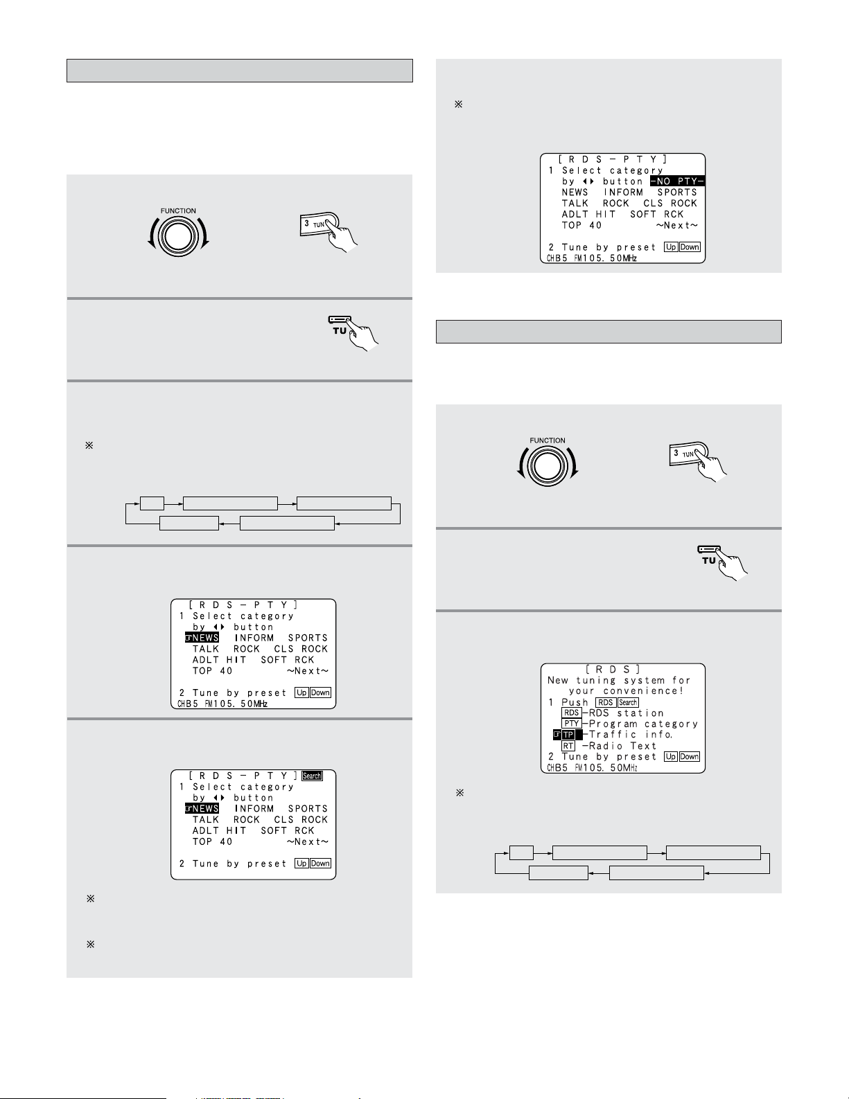
69
Basic Operation
5
Press the CHANNEL button.
• Automatically begin the PTY search operation.
If there is no station broadcasting the designated
program type with above operation, all the reception
bands are searched.
The station name is displayed on the display after
searching stops.
PTY search
1
Set the input source to “TUNER”.
3
Press the RDS SEARCH button until “PTY
SEARCH” appears on the display.
The main unit’s display switches as follows each time
the RDS SEARCH button is pressed.
• Use this function to find RDS stations broadcasting a
designated program type (PTY).
• For a description of each program type, refer to “Program
Type (PTY)”.
RDS SEARCHFM PTY SEARCH
RT ON TP SEARCH
Display
4
Watching the display, press the CURSOR
FF
or
GG
button to call out the desired program type.
6
To continue searching, repeat step 3.
If no other station broadcasting the designated
program type is found when all the frequencies are
searched, “NO PROGRAMME” is displayed.
(Main unit)
TP search
1
Set the input source to “TUNER”.
3
Press the RDS SEARCH button until “TP
SEARCH” appears on the display.
• Use this function to find RDS SEARCH stations broadcasting
traffic program (TP stations).
RDS SEARCHFM PTY SEARCH
RT ON TP SEARCH
Display
The main unit’s display switches as follows each time
the RDS SEARCH button is pressed.
(Main unit)
(Remote control unit
in the AMP mode)
2
Press the TU (TUNER)
button to select the TUNER
mode.
(Remote control unit)
(Remote control unit
in the AMP mode)
2
Press the TU (TUNER)
button to select the TUNER
mode.
(Remote control unit)
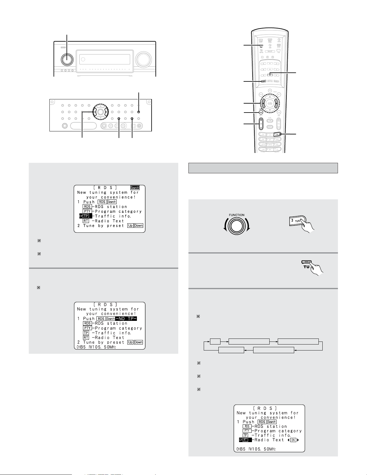
70
Basic Operation
4
Press the CHANNEL button.
• Automatically begin the TP search operation.
If no TP station is found with above operation, all the
reception bands are searched.
The station name is displayed on the display after
searching stops.
5
To continue searching, repeat step 3.
If no other TP station is found when all the frequencies
are searched, “NO PROGRAMME” is displayed.
CHANNEL
TU
BAND
TUNING –
TUNER
CURSORFG
RDS SEARCH
(AMP mode)
RT (Radio Text)
1
Set the input source to “TUNER”.
3
Press the RDS SEARCH button until “RT ON”
appears on the display.
The main unit’s display switches as follows each time
the RDS SEARCH button is pressed.
•“RT” appears on the display when radio text data is
received.
RDS SEARCHFM PTY SEARCH
RT ON TP SEARCH
Display
While receiving an RDS broadcast station, the text
data broadcast from the station is displayed.
To turn the display off, press the CURSOR
FF
or
GG
button.
If no text data is being broadcast, “NO TEXT DATA” is
displayed.
(Main unit)
(Remote control unit
in the AMP mode)
2
Press the TU (TUNER)
button to select the TUNER
mode.
(Remote control unit)
FUNCTION
FG
CURSOR
STATUS
BAND TUNING –
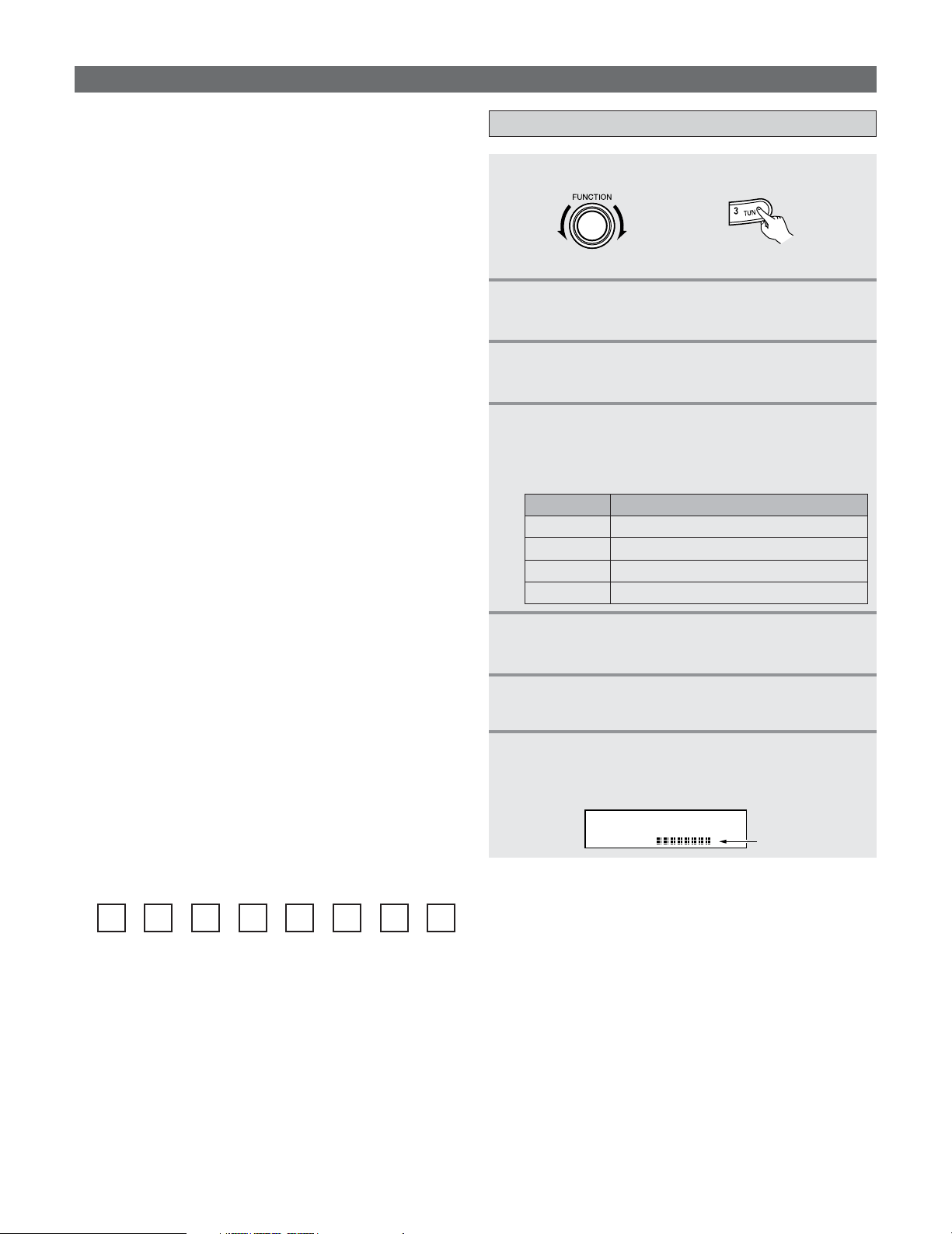
71
Basic Operation
XM Satellite Radio
2 ABOUT XM SATELLITE RADIO
XM Satellite Radio offers an extraordinary variety of
commercial-free music, plus the best in sports, news, talk
and entertainment. XM is broadcast in superior digital audio
from coast to coast. From rock to reggae, from classical to
hip hop, XM has something for every music fan. XM’s
dedication to playing the richest selection of music is
matched by its passion for live sporting events, talk radio,
up-to-the-minute news, stand-up comedy, children’s
programming, and much more. For U.S. customers,
information about XM Satellite Radio is available online at
www.xmradio.com. For Canadian customers, information
about XM Canada is online at www.xmradio.ca.
2
XM READY
®
LEGAL
Hardware and required monthly subscription sold
separately. Other fees and taxes, including a one-time
activation fee may apply. Subscription fee is consumer
only. All fees and programming subject to change.
Channels with frequent explicit language are indicated with
an XL. Channel blocking is available for XM radio receivers
by calling 1-800-XMRADIO (US residents) and 1-877-GET-
XMSR (Canadian residents).
For a full listing of the XM commercial-free channels and
advertising-supported channels, visit lineup.xmradio.com
(US residents) or xmradio.ca (Canadian residents).
Subscriptions subject to Customer Agreement available at
xmradio.com (US residents) and xmradio.ca (Canadian
residents). Only available in the 48 contiguous United
States and Canada. 2006 XM Satellite Radio Inc. All rights
reserved. All other trademarks are the property of their
respective owners.
Checking the XM signal strength and Radio ID
1
Set the input source to “TUNER”.
2
Press the TU (TUNER) button to select the
TUNER mode.
3
Watching the display, press the BAND button
to select the XM mode.
(Main unit) (Remote control unit in the AMP mode)
4
Press the STATUS button on the main unit
until “SIGNAL” is displayed.
• The display changes as shown below according to
the receiving condition.
5
Adjust the antenna location until
“SIGNAL:GOOD” is displayed.
ConditionDisplay
NO
GOOD Signal strength is good
MARGINAL Signal strength is marginal
WEAK Signal strength is poor
Loss of the signal
7
Press the TUNING – button to select channel 0
(XM000
).
• The Radio ID is displayed.
XM000 RADIO ID
Radio ID
6
Press the STATUS button until the XM channel
(ex.XM001) is displayed.
2 XM READY
®
SUBSCRIPTIONS
Once you have installed the XM Mini-Tuner Dock, inserted
the XM Mini-Tuner, connected the XM Dock to your XM
Ready
®
home audio system, and installed the antenna,
you are ready to subscribe and begin receiving XM
programming. There are three places to find your eight
character XM Radio ID: on the XM Mini-Tuner, on the XM
Mini-Tuner package, and on XM Channel 0. Record the
Radio ID in the following eight squares for reference.
Note: The XM Radio ID does not use the letters “I”, “O”,
“S” or “F”. Activate your XM Satellite Radio service in the
U.S. online at http://activate.xmradio.com or call 1-800-
XM-RADIO (1-800-967-2346). You will need a major credit
card. XM will send a signal from the satellites to activate
the full channel lineup. Activation normally takes 10 to 15
minutes, but during peak busy periods you may need to
keep your XM Ready home audio system on for up to an
hour. When you can access the full channel lineup on your
XM Ready home audio system you are done. For more
information or to subscribe in Canada, visit XM on the Web
at www.xmradio.ca or call XM’s Listener Care at 1-877-
GET-XMSR (1-877-438-9677).
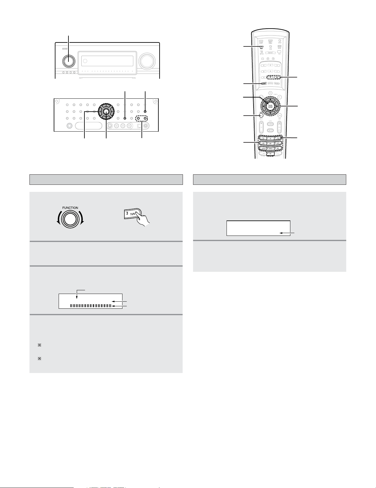
72
Basic Operation
Channel selection
1
Set the input source to “TUNER”.
2
Press the TU (TUNER) button to select the
TUNER mode.
3
Watching the display, press the BAND button
to select the XM mode.
(Main unit) (Remote control unit in the AMP mode)
XM040 DeepTrks
Song title/Artist name
Channel name
Channel number
4
Press the TUNING button to reach the desired
channel.
The channel changes continuously when you press
and hold the TUNING button.
When the artist name and song title are received, they
are displayed.
Category search
1
Press the CURSOR
FF
or
GG
button in the XM
mode.
• The current category name is displayed.
2
Press the CURSOR
FF
or
GG
button to select the
category, and press the
CURSOR
DD
or
HH
button
to select the channel within the selected category.
CAT: Rock
XM040 DeepTrks
Channel Category
TU
BAND
TUNING
TUNER
CURSOR
SEARCH
NUMBER
ENTER
(AMP mode)
FUNCTION
BAND
STATUS
CURSOR
ENTER
TUNING
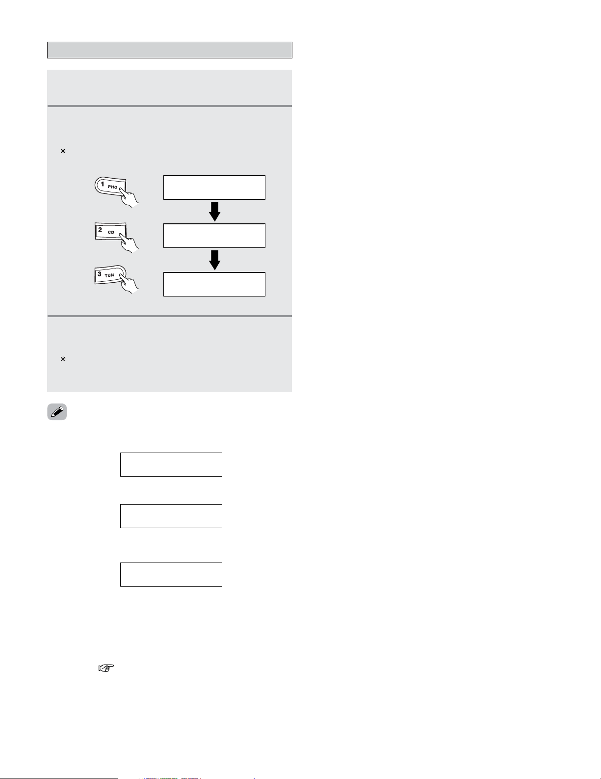
73
Basic Operation
Direct access of channels
1
Press the SEARCH button in the XM mode.
2
Press the NUMBER buttons to enter the
desired channel.
For example, if you want to access channel 123
(ex.XM123) press the NUMBER buttons as shown below.
XM001
DIRECT SEARCH
DIRECT SEARCH
DIRECT SEARCH
XM012
XM123
(Remote control unit)
3
Once all number have been input, press the
ENTER button to change the channel.
If the next NUMBER button is not pressed within
several seconds, the channel automatically switches to
the channel number that was input.
•“UPDATING” is displayed while updating encryption code.
• When the selected channel is not available, “XM– – –” is
displayed.
LOADING
XM040 DeepTrks
UPDATING
XM040 DeepTrks
XM---
• Information on the artist name, song title, category and
signal level can be checked using the STATUS button on the
main unit.
• The XM Satellite Radio channels can be preset in the same
way as AM/FM band.
Please refer to “Preset memory” and “Recalling preset
stations” ( page 66, 67).
• “LOADING” is displayed while receiving the channel or
information.
74
Basic Operation
Using the Network Audio Function
Internet radio function
• The AVR-5805CI can be connected to a network by cable to listen to Internet radio or music files stored on computers.
Internet radio refers to radio programs broadcast over the
Internet.
There are many stations throughout the world broadcasting
Internet radio programs. These stations are of all sizes and
types, some run by individuals, others by ground wave
broadcast stations.
While ground wave radio stations can only be listened to within
the range in which the waves reach, Internet radio can be
listened to anywhere in the world.
The AVR-5805CI is equipped with the following Internet radio
functions:
• Stations can be selected by genre and region.
• Up to 56 Internet radio stations can be preset.
• MP3 format Internet radio programs can be listened to.
•Your favorite radio stations can be registered by accessing
the exclusive DENON Internet radio URL using a computer’s
browser. (The AV amplifier automatically downloads the
registration settings (approximately once every other day))
(This is managed separately for each unit, so a MAC address
or e-mail address must be registered.) ( page 139)
Exclusive URL : http://www
.radiodenon.com
(accessible after connection to an Internet radio station.)
2 vTuner
The AVR-5805CI’s Internet radio station list uses “vTuner”,
a radio station database service. This database service is
edited and prepared for the AVR-5805CI.
The AVR-5805CI is equipped with a network audio playback
function allowing music files stored on a computer to be
played via a LAN (Local Area Network).
The AVR-5805CI’s network audio playback function connects
to servers using the following technologies:
•Windows Media Connect
•Windows Media DRM 10 (for network devices)
Music server function
• The preparations described below must be made in order to
use the Internet radio and music server functions.
2
Broadband Internet connection
A broadband connection to the Internet is necessary in
order to use the AVR-5805CI’s Internet radio function.
NOTE:
• You must have a contract with an Internet Service
Provider (ISP) in order to connect to the Internet. For
instructions on connecting to the Internet, contact your
ISP or a computer store.
If you already have a broadband Internet connection there
is no need to take out another contract.
2
Modem
A modem is a device for exchanging signals over the
Internet using a broadband connection. Some are
integrated into routers. For instructions on connecting to
the Internet, contact your ISP or a computer store.
System requirements
2 Router
A router is a device for connecting multiple pieces of
equipment (computers, the AVR-5805CI, etc.) to the
Internet simultaneously.
When using the AVR-5805CI, we recommend a router
equipped with the following functions:
• Built-in DHCP (Dynamic Host Configuration Protocol)
server.
Function for automatically assigning the device’s IP address
on the LAN.
• Built-in 100BASE-TX switch
When connecting multiple devices, it is recommended to
have a built-in switching hub with a speed of 100 Mbps or
greater.
NOTE:
• The type of router that can be used differs for different
ISPs. For details, contact your ISP or a computer store.
2
Ethernet cable (CAT-5)
The AVR-5805CI does not come with an Ethernet cable.
Purchase one of the required length.
Some flat type Ethernet cables are easily affected by noise.
We recommend using a normal type cable.
If the sound is broken in an environment with the electric
products subject to much power noise or a noisy network
environment, use a shielded type Ethernet cable. This
could improve the sound.
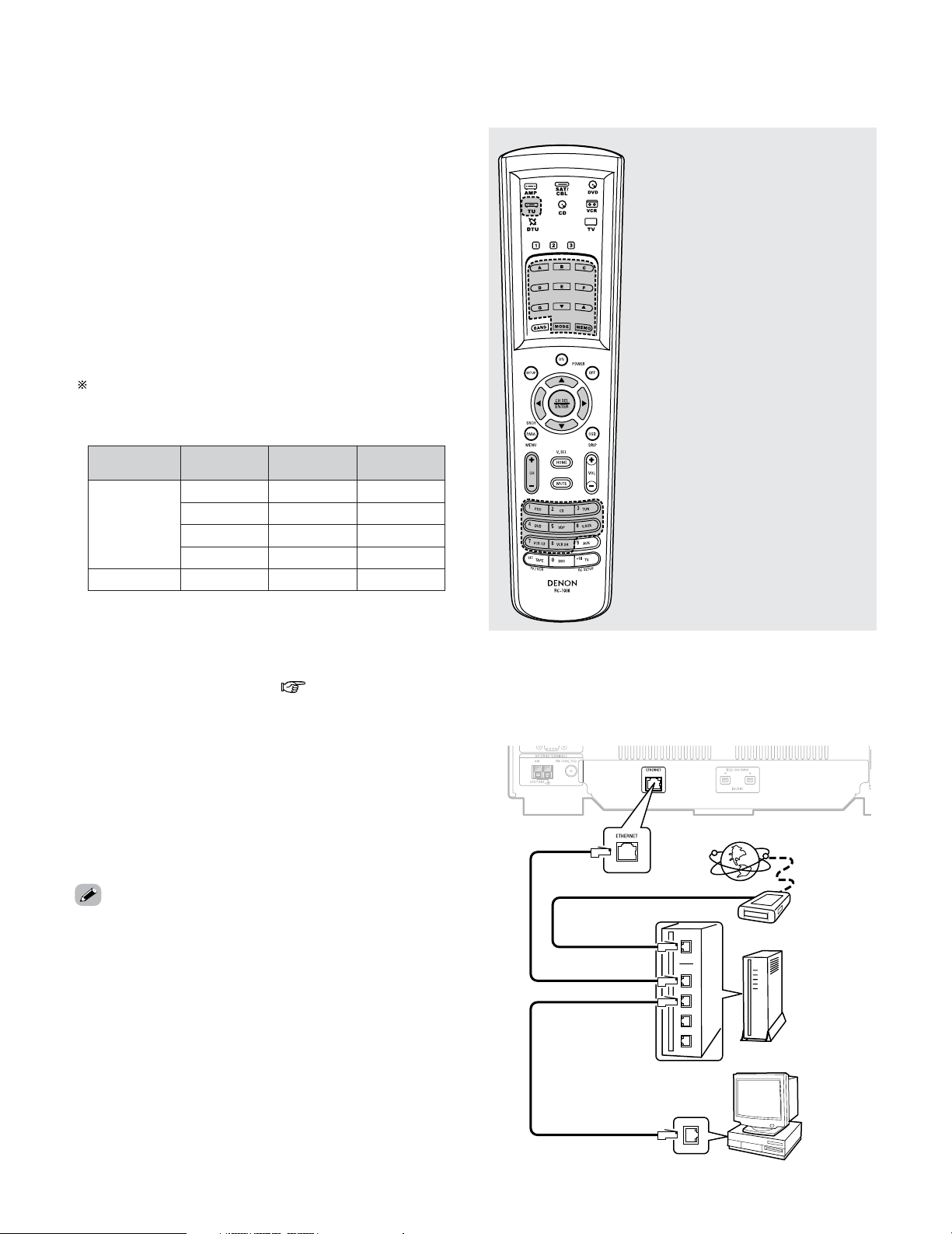
75
Basic Operation
2 Personal Computer
Install “Windows Media Connect” on your computer.
The required system for forming a music server is as
described below.
1)OS (Operating System):
Windows® XP Service pack2
2)Processor:
Intel Pentium
II or AMD processor, etc.
We recommend 1 GHz or greater.
3)RAM:
Min. 128 MB, we recommend 256 MB or greater.
4)Software:
.NET Framework 1.1
5)Internet browser:
Microsoft Internet Explorer 5.01 or later
• LAN port required
• 300 MB or greater free hard disc space required
Extra free space is necessary to store music files.
The following table gives an approximate estimate of the
required free space.
Per one hour
Per one
minute
Bit rateFormat
060 MB0.1 MB0128 kbps
MP3 / WMA
090 MB1.5 MB0192 kbps
120 MB0.2 MB0256 kbps
180 MB0.3 MB0392 kbps
600 MB.10 MB1400 kbpsWAV (LPCM)
2 Others
•When the contract with your provider is of the type by
which the network settings are made manually, you must
make the “Network Setup” ( page 138, 139).
• The AVR-5805CI is not compatible with PPPoE. If your
contract is of the PPPoE setting type, you need a PPPoE-
compatible router.
• For some ISPs (Internet Service Providers), you may have
to make proxy server settings in order to use the Internet
radio function. If proxy server settings for connecting to the
Internet have been made on the computer, make the same
settings on the AVR-5805CI.
• The AVR-5805CI is designed to make the network settings
automatically using the DHCP and Auto IP functions.
A ~ G :Preset memory blocks
•, ª : Character search
MODE : Configuration mode
selection
MEMO :Preset and favorite
registration
•
,
ª
, 0, 1 : Cursor up, down, left and
right
ENTER : Enter settings
CH +, – :Preset channel selection
1 ~ 8 :Preset numbers
2 TU (Tuner) / DTU (Digital tuner) system buttons
The tuner or digital tuner system buttons shown on the
diagram below are used for Network Audio operations.
2 Connections
Connect one side of the Ethernet cable (CAT-5) to the
ETHERNET terminal on the AVR-5805CI’s rear panel, the
other side to the router.
Internet radio
Modem
To WAN side
To LAN side port
To LAN side port
Router
Computer
LAN port/ETHERNET port
• No signals are output to the digital output terminals when
playing copyright-protected music files.
• The AVR-5805CI is compatible with “MPEG-1 Audio Layer-
3” MP3 files (with sampling frequencies of 32, 44.1 or 48
kHz). It is not compatible with “MPEG-2 Audio Layer-3”,
“MPEG-2.5 Audio Layer-3”, “MP1” or “MP2” files.
• The AVR-5805CI is compatible with bit rates of 32 to 320
kbps for MP3 files and 48 to 192 kbps for WMA files.
• The AVR-5805CI is compatible with WMA files with
sampling frequencies of 32, 44.1 or 48 kHz.
• The AVR-5805CI is compatible with MP3 ID3-Tag (Ver.2).
• The AVR-5805CI is compatible with WMA meta tags.
•With the AVR-5805CI, the folder names, file names, etc., can
be displayed on the main unit’s display and the OSD. Up to
95 characters can be displayed. A “. (period)” is displayed in
place of non-compatible characters.
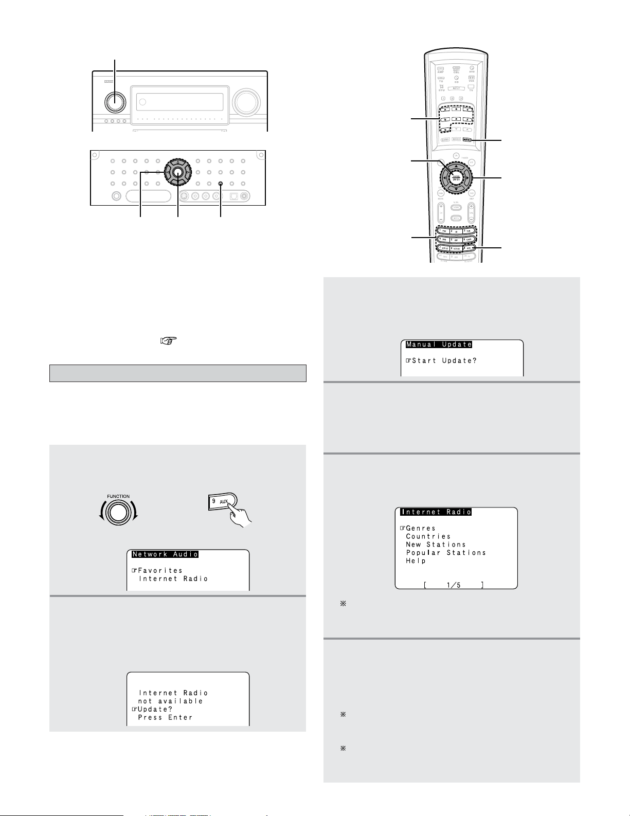
76
Basic Operation
2 Network settings
When using a broadband router (DHCP function), the
network settings are made automatically, so there is no
need to make the settings from the setup menu.
If the broadband router’s DHCP function is turned off, make
the “Network Setup” ( page 138, 139).
• The required system connections and settings must be
made in order to listen to Internet radio.
“Update?” appears on the display when connecting to an
Internet radio station for the first time.
Listening to Internet radio
1
Either turn the FUNCTION knob or press the
AUX button to select “NetAudio” (AMPmode).
• The “Network Audio” menu appears.
2
Press the CURSOR
DD
or
HH
button to select
“Internet Radio”, then press the
ENTER or
CURSOR
GG
button.
• The initial screen when not connected to the Internet
is displayed.
(Remote control unit in the AMP mode)(Main unit)
CURSOR
AUX
MEMORY
MEMORY BLOCK
NUMBER
ENTER
(AMP mode)
During playback, press the ENTER button once to
pause playback, then press ENTER button again to
resume playback.
If the ENTER button is pressed and held in for more than
two seconds when in the play or pause mode, playback
stops and the previous menu window reappears.
Finally, the list of Internet radio stations is displayed
and those that can be played are indicated by the “
∗
”
mark in front of them.
4
Press the ENTER or CURSOR
GG
button once
again.
• The latest list of radio stations is downloaded from
the vTuner site. (Several minutes are required for this
download.)
5
Press the CURSOR
DD
or
HH
button to select the
desired setting item, then press the
ENTER or
CURSOR
GG
button.
6
Press the CURSOR
DD
or
HH
button to select the
desired radio station, then press the
ENTER or
CURSOR
GG
button.
•Connection starts, and the station starts playing
once the buffer reaches “100%”.
FUNCTION
ENTER
MEMORY
CURSOR
3
Connecting to an Internet radio station for the
first time:
Press the
ENTER or CURSOR
GG
button.
• The update screen appears.
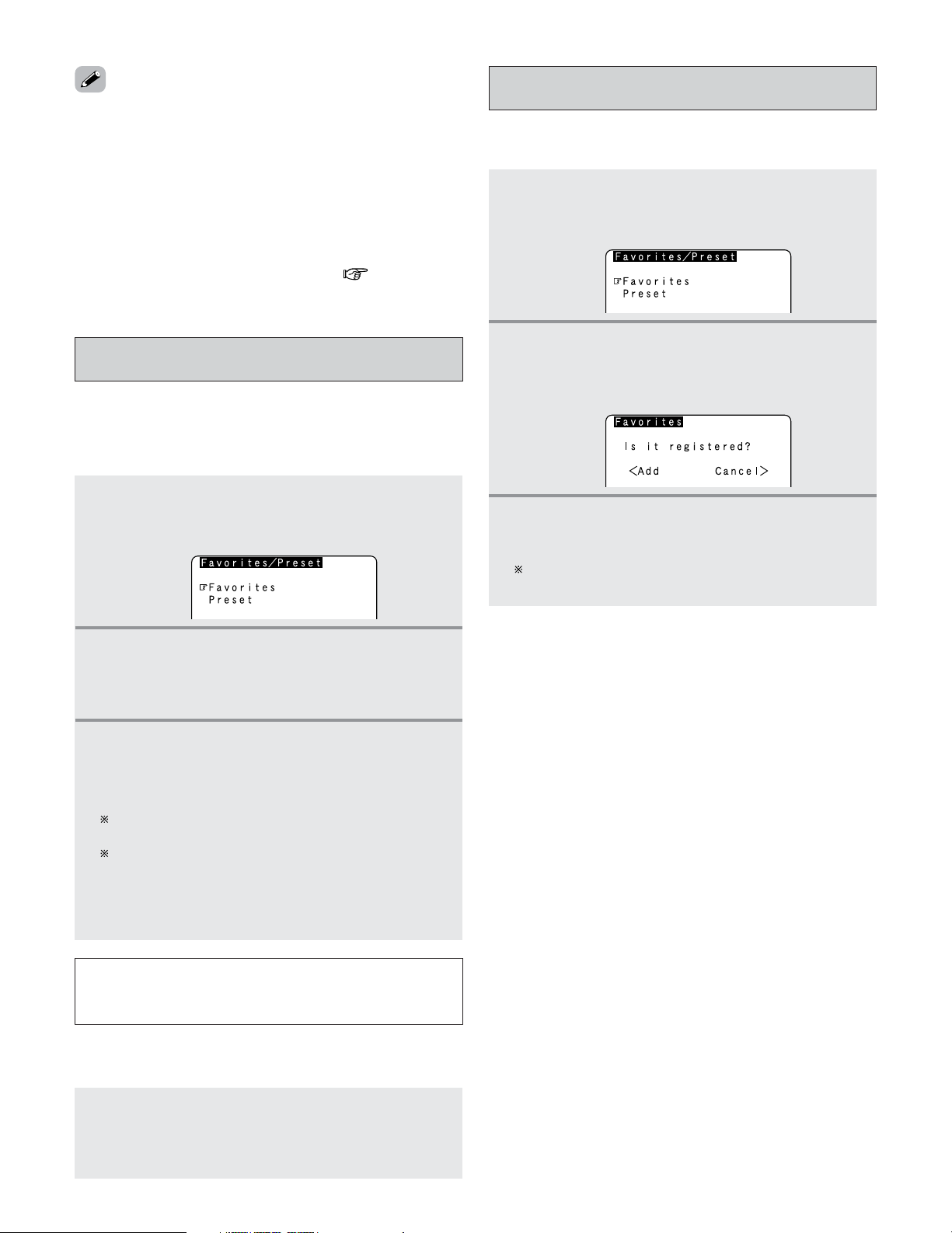
77
Basic Operation
If no button is operated for approximately ten
seconds, the regular display reappears.
Registered presettings can be checked on the on
screen display.
The presettings can only be displayed with the on
screen display when the “NetAudio” function is
selected.
NOTE:
• Registered presettings are deleted when they are
overwritten.
When the “NetAudio” function is selected, press a
MEMORY BLOCK (A ~ G) button, then press a
NUMBER (1 ~ 8) button.
• The connection is made automatically and playback starts.
2
Listening to preset Internet radio stations
• There are two ways to register stations: by presetting them
or by storing them in your favorites.
• Stations that are preset can be tuned in directly from the
remote control unit.
Presetting (registering) Internet radio
stations
1
Press the MEMORY button while playing the
Internet radio station you want to register.
• The registration menu appears.
2
Press the CURSOR
DD
or
HH
button to select
“Preset”, then press the
ENTER or CURSOR
GG
button.
• The preset registration screen appears.
3
Press a MEMORY BLOCK (A ~ G) button, then
press a
NUMBER (1 ~ 8) button to register the
station at the desired preset channel.
• This completes registration.
• There are many Internet radio stations on the Internet. The
programs they broadcast and their bit rates vary widely.
Generally, the higher the bit rate, the higher the sound
quality, but streamed music or sound may be broken if the
communication lines or servers are busy. Inversely,
programs with low bit rates have lower sound quality but
tend to be more stable.
• “Server Full” or “Connection Down” is displayed if the
station is congested or if it is not broadcasting.
• The time for which the on screen display is displayed can be
set at “Setting the On Screen Display” ( page 115).
•Your favorites are listed at the top of the menu screen, so
registered stations can be tuned in easily.
Registering Internet radio stations in your
favorites
1
Press the MEMORY button while playing the
Internet radio station you want to register.
• The registration menu appears.
2
Press the CURSOR
DD
or
HH
button to select
“Favorites”, then press the
ENTER or CURSOR
GG
button.
• The favorites registration screen appears.
3
Press the CURSOR
FF
button to register the
station.
To cancel without registering, press the CURSOR
GG
button.
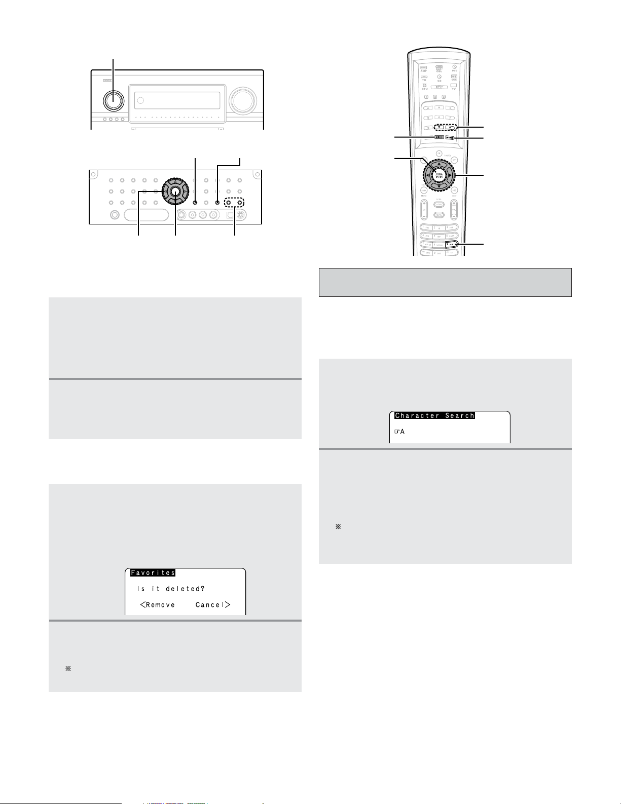
78
Basic Operation
2 Listening to Internet radio stations registered in
your favorites
1
When the “NetAudio” function is selected,
press the
CURSOR
DD
or
HH
button to select
“Favorites”, then press the
ENTER or CURSOR
GG
button.
• The Internet radio stations registered in your
favorites are displayed.
2
Press the CURSOR
DD
or
HH
button to select the
desired radio station, then press the
ENTER or
CURSOR
GG
button.
• Playback starts.
1
At the screen on which the Internet radio
stations registered in your favorites are
displayed, press the
CURSOR
DD
or
HH
button to
choose the radio station you want to delete,
then press the
MEMORY button.
• The delete screen appears.
2
Deleting radio stations from your favorites
2
Press the CURSOR
FF
button to delete the
station.
To cancel without deleting, press the CURSOR
GG
button.
• The character search function (searching by first letter) can
be used to select the desired item from the menu screen
displaying the list of Internet radio stations or music files
stored on the computer.
Character search function (searching by
first letter)
1
While the menu screen is displayed, press the
TUNING button.
• The character search screen appears.
If there is more than one item starting with the letter
selected in step 2, the items are displayed in
alphabetical order.
2
Press the TUNING button to select the first
letter of the item you want to search for.
• After several seconds, the menu screen is displayed
with the cursor set to the item starting with the letter
selected in step 2.
CURSOR
AUX
MEMORY
ENTER
MODE
TUNING
(AMP mode)
FUNCTION
ENTER
MODE
MEMORY
CURSOR
TUNING
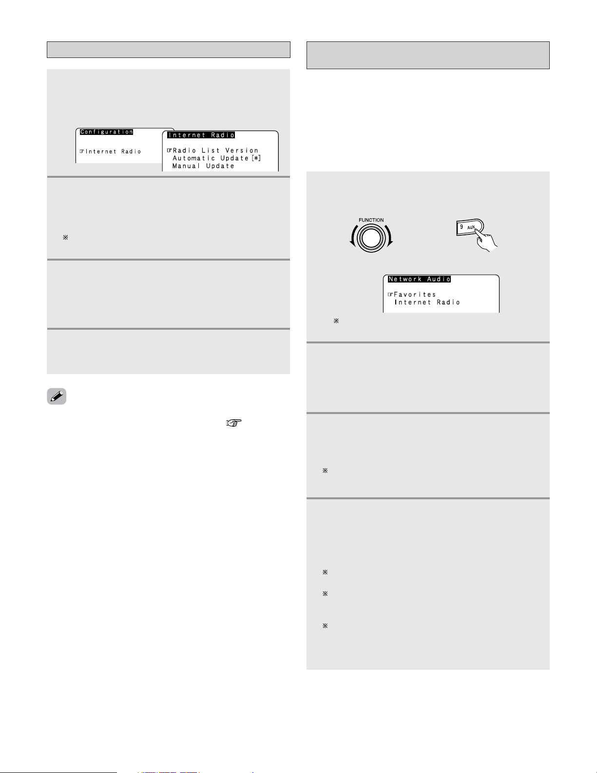
79
Basic Operation
Select “Radio List Version” to display the current
version.
Updating the list of radio stations
1
Press the MODE button to select the
configuration mode, then press the
ENTER or
CURSOR
GG
button.
• The settings screen appears.
2
Press the CURSOR
DD
or
HH
button to select
“Automatic Update” or “Manual Update”,
then press the
ENTER or CURSOR
GG
button.
• The update screen appears.
3
-1
When “Automatic Update” is selected:
Press the
ENTER orCURSOR
GG
button to select
“Yes”.
• The list of radio stations is updated approximately
once every other day.
3
-2
When “Manual Update” is selected:
Press the
ENTER or CURSOR
GG
button.
• The list of radio stations is updated this one time.
• When “Yes” is set for “Automatic Update”, set “Power
Saving” in the “Network Setup” to “OFF”( page 139).
When used with “Power Saving” set to “ON”, we
recommend performing the “Manual Update” procedure
periodically (about once a week).
The host names of the computer(s) (music
server(s)) on the network are displayed.
• The necessary system connections and settings must be
made in order to play music files.
• This procedure is used to play music files (in WMA, MP3 and
WAV format) stored on computers (music servers)
connected to the AVR-5805CI via the network.
• The computer’s server program must be launched before
using this function. For details, refer to the server program’s
operating instructions.
Playing music files stored on the computer
(music server)
1
Either turn the FUNCTION knob or press the
AUX button to select “NetAudio” (AMPmode).
• The “Network Audio” menu appears.
(Main unit) (Remote control unit in the AMP mode)
2
Press the CURSOR
DD
or
HH
button to select the
host name of the computer (music server) on
which the music file you want to play is
located, then press the
ENTER or CURSOR
GG
button.
3
Press the CURSOR
DD
or
HH
button to select the
search item orthe desired folder, then press the
ENTER or CURSOR
GG
button.
Playable music files are indicated by the “
∗
” mark in
front of them.
4
Press the CURSOR
DD
or
HH
button to select the
music file, then press the
ENTER or CURSOR
GG
button.
•Connection starts, and playback starts once the
buffer reaches “100%”.
Press the CURSOR
HH
button to select the next file, the
CURSOR
DD
button to select the previous file.
During playback, press the ENTER button once to pause
playback, then press the ENTER button again to resume
playback.
If the ENTER button is pressed and held in for more
than 2 seconds when in the play or pause mode,
playback stops and the previous menu screen
reappears.
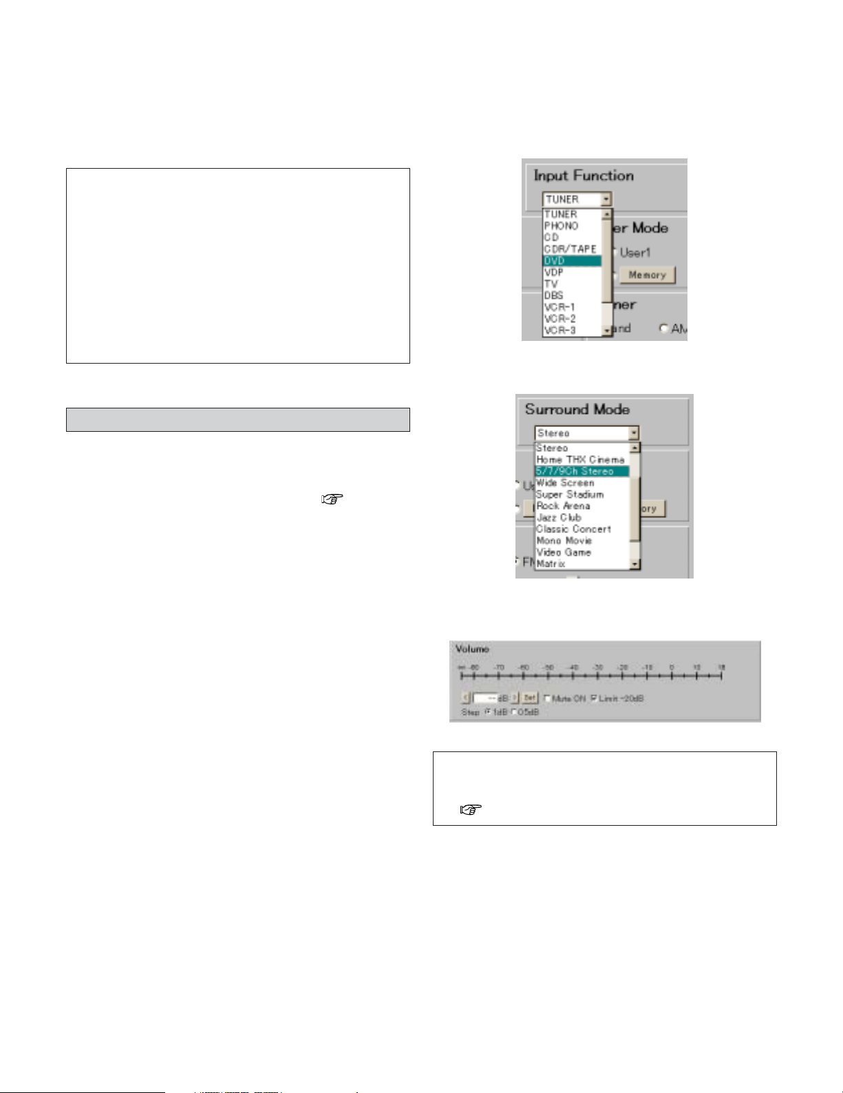
80
Basic Operation
• The same operations as for Internet radio stations can be
used to preset music files or register them in your favorites
and play them.
NOTE:
• Registered presettings are deleted when they are
overwritten.
• When the operations describe below are performed, the
music server database is updated and it may no longer be
possible to play the music files that have been preset or
registered in your favorites:
• When the music server is stopped and restarted.
• When music files are deleted from or added to the
music server.
• When using an ESCIENT server, place “ESCIENT” before
the server name.
2
Playing music files that have been preset or
registered in your favorites
Operating the AVR-5805CI using a browser
• Internet Explorer can be used on the computer connected to
the AVR-5805CI over the network to operate the AVR-
5805CI.
• Check the AVR-5805CI’s IP address ( page 138)
beforehand and input this IP address in Internet Explorer to
display the AVR-5805CI’s control panel.
• Operate in the same way as with normal Internet browsing
to control the AVR-5805CI.
2 Examples of web control operation screens
The settings of the setup items are the same as with
normal operations. Refer to “System Setup”.
Below are some examples of operation screens.
Function selection screen
Surround mode selection screen
Volume control screen
NOTE:
•To use this function, set “Standby Mode Power Saving”
at “Network Option” under “Network Setup” to “OFF”
( page 139).
Advanced Operation
81
Remote control unit
•With the attached remote control unit, the display changes
according to the mode being operated.
HOME
MODE
SELECTOR
AMP
2
Operate the DENON audio component (CD,
TAPE, TUNER).
For details, refer to the component’s operating
instructions.
• It may not be possible to use some of the buttons,
depending on the model and age of your equipment.
•When a remote control code is sent, the icon for the mode
of the device to which that code belongs flashes.
• The HOME button is used to return to the “AMP” (“AMP”,
“ZONE2”, “ZONE3”, “ZONE4” or “SYSTEM CALL”) mode
when in any mode other than “AMP”.
1
Press the MODE SELECTOR button for the
device to be operated.
• The indicator of the device to be operated blinks.
: AMP / ZONE2 / ZONE3 /
ZONE4 / SYSTEM CALL
: TUNER
:DIGITAL TUNER
:SATELLITE / CABLE
: CD / CDR
: DVD / DVDR
: VCR / TAPE
:TV
Operating DENON audio components
This function switches as shown below each time one
of the AMP button is pressed.
AMP
SYSTEM CALL
ZONE2 ZONE3
ZONE4
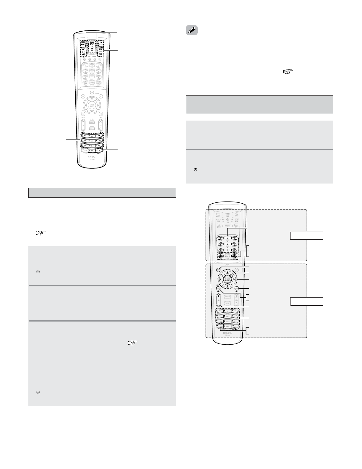
82
Advanced Operation
1
Press the MODE SELECTOR button for the
device to be set in the preset memory.
Presetting is not possible for the AMP, ZONE2,
ZONE3, ZONE4, TUNER and SYSTEM CALL modes.
2
Press and hold the RC SETUP button for at
least 3 seconds.
• The IR segment blinks twice and the input mode is
set.
• There may be several preset codes for some brands. If the
remote control unit does not work properly with one code,
try inputting another code.
• Buttons that have been learned have priority over the signals
set with the preset memory function. If a learned button
setting is not needed, please erase it ( page 86).
Setting the preset memory function
• The various devices can be operated by setting the preset
memory on the attached remote control unit.
For some models the remote control unit or the device may
not operate properly. In this case, use the learning function
( page 84) to store your device’s remote control signals
in the attached remote control unit.
3
Input the (5-digit) number for the brand of the
device to be set in the preset memory, as shown
on the list of preset codes ( End of this
manual).
• The IR segment blinks twice when the memory is
set.
• When a preset code is transmitted, the mode
indicator for the device to which that code belongs
blinks.
The input mode is canceled if no operation is
performed for 10 seconds.
1
Press the MODE SELECTOR button for the
device to be operated.
• The indicator of the device to be operated blinks.
2
Operate the component.
For details, refer to the component’s operating
instructions.
Operating a component stored in the
preset memory
MODE SELECTOR
RC SETUP
IR segment
NUMBER
0 ~ 9, +10
TV/VCR
SFT
MENU
SRCH
BAND, MODE, MEMO
SOURCE (SRC) OFF
SOURCE (SRC) ON
ENTER
SETUP
DISP
CH
+, –
A ~ G
,
ª
,
•
1
,
8
9
,
6
7
,
3
,
2
D
H
F
G
EL Display
Buttons
q
,
e
83
Advanced Operation
Tape deck
TV
/
VCR
0 ~ 9, +10
SFT
DISP
MENU
SRCH
CH +–
DD HH FF GG
ENTER
SETUP
MEMO
MODE
BAND
•ª
3
2
SOURCE ON
SOURCE OFF
A ~ G
67
89
1
Special remarks
Default setting
(preset code)
Buttons
EL Display
MODE SELECTOR
Satellite tuner
or Cable TV
TV
(Monitor)
DVD player
or
DVD recorder
TunerVideo deck
CD player
or
CD recorder
Device operated
––
RDS search/
XM direct search
––– –
––
Preset channel
selection
Station selection Station selectionStation selection Station selection
CD
Play
Manual search
(forward / reverse)
Auto search
(to beginning of
track)
–
–
–
–
–
–
–
–
DENON CD
(31867)
Pause
Stop
q
Play
Manual search
(forward / reverse)
Auto search
(to beginning of
track)
–
–
–
–
–
–
–
–
Pause
Stop
q
TU
–
–
–
–
–
Preset memory block
AM/FM/XM
switching
Tuning
Auto/Manual
switching
–
Preset memory
–
–
–
–
DVD
Play
Manual search
(forward / reverse)
Auto search
(to beginning of
track)
Power on
Power off
–
–
–
–
Setup
–
DENON DVD
(
41470
)
Pause
Stop
q
,
w
SAT/CBL
–
–
–
Power on
Power off
–
–
–
–
Setup
–
RCA SAT
(
00392
)
–
–
VCR
Play
Manual search
(forward / reverse)
Auto search
(to beginning of
track)
Power on
Power off
–
–
–
–
Setup
–
HITACHI VCR
(
20000
)
Pause
Stop
q
TV
–
–
–
Power on
Power off
–
–
–
–
Setup
–
HITACHI TV
(
11145
)
–
–
e
–
Track selection
–
–
–
–
–
–
Track selection
–
–
–
–
–
Preset memory block
selection
Preset station
selection (0 ~ 8)/
XM channel selection
(0 ~ 9)
–
–
–
–
–
–
Number input/station
selection
Enter
–
Menu
Display selection
Cursor operation
–
Station selection
Enter
–
Menu
–
Cursor operation
–
Station selection
Enter
–
Menu
Guide
Cursor operation
–
Station selection
Enter
Input mode selection
Menu
Guide
Cursor operation
–
2 Functions of buttons for the different devices
Special remarks:
q It is only possible to set the preset memory for one device per mode.
w Note that the function names of the DVD buttons on the remote control unit may differ for some brands. Check beforehand.
e The CD, VCR or DVD buttons can be assigned to a TV or satellite tuner (or cable TV) ( page 85).
Advanced Operation
84
• If your AV device is a brand other than DENON or if operation
is not possible using the preset memory function, the signals
of a remote control unit of that device can be stored in the
AVR-5805CI’s remote control unit.
• For some remote control units, it may not be possible to
learn the signals or the device may not operate properly after
the signals are learnt. In this case, use the remote control
unit of that device.
1
Press and hold the RC SETUP button for at
least 3 seconds.
• The IR segment blinks twice.
2
Press the 9, 7, 5 button (9
→→
7
→→
5) in that
order.
• The IR segment blinks twice and the learning mode
is set.
3
Press the MODE SELECTOR button for the
device to be operated.
Learning is not possible for the AMP, ZONE2, ZONE3,
ZONE4 and SYSTEM CALL modes.
Setting the learning function
5
Point the remote control units straight at each
other and press and hold in the button on the
other remote control unit to be learnt on the
AVR-5805CI’s remote control unit.
•The display turns on again and the IR segment blinks
twice to indicate that the code is successfully
captured.
Other remote
control unit
Other buttons can be learnt by repeating steps 4 and 5.
The mode can be switched by pressing a MODE
SELECTOR button.
If the IR segment displays one long blink, a leaning
error has occurred. Try repeating this step again until a
successful capture occurs.
•To cancel the learning setup mode, press and hold the RC
SETUP button for at least 3 seconds.
6
Press and hold the RC SETUP button for at
least 3 seconds.
• The IR segment blinks twice and the setting is
completed.
4
Press the button to be set.
• The display will go off and the unit will enter the
learning standby mode.
If a button that cannot be learnt is pressed, the IR
segment lights and the setting is canceled.
Cannot be set at the HOME button.
NOTE:
• Do not try to learn anything to the RC SETUP button.
•A series of operations can be registered at a single button.
• This function makes it possible to for example turn the
amplifier’s power on, select the input source, turn the
monitor power’s on, turn the source device’s power on and
start playback, all by pressing a single button once.
• Up to 32 signals each can be stored at the SYSTEM CALL
button (1, 2 or 3).
Using the system call function
The AVR-5805CI’s remote control
unit (RC-1036)
NUMBER
RC SETUP
IR segment
AMP
MODE SELECTOR
SYSTEM CALL
CHANNEL

85
Advanced Operation
1
Press and hold the RC SETUP button for at
least 3 seconds.
• The IR segment blinks twice.
2
Press the 9, 7, 8 button (9
→→
7
→→
8) in that order.
• The IR segment blinks twice and the system call
registration mode is set.
3
Press the SYSTEM CALL button (1, 2 or 3) for
which you want to register the operations.
4
Press the buttons you want to register in the
order of the operations to be performed.
Example:Press the ON button.
↓
Press the CD button of the MODE
SELECTOR button.
↓
Press the
1 button.
The mode can be switched by pressing a MODE
SELECTOR button.
5
Repeat steps 3, 4 to register the desired
buttons.
6
Press and hold the RC SETUP button for at
least 3 seconds.
• The IR segment blinks twice and the setting is
completed.
1
Press the AMP button to select “SYSTEM
CALL”.
2
Press the SYSTEM CALL button (1, 2 or 3) at
which the operation are registered
• The stored signals are transmitted successively.
2
Press the 9, 8, 4 button (9
→→
8
→→
4) in that order.
• The IR segment blinks twice and the punch through
setting mode is set.
3
Press the MODE SELECTOR button forthe device
to be punched through (CD, DVD or VCR).
4
Press the button to be punched through (1, 2,
6, 7, 8, 9 or 3).
5
Press the MODE SELECTOR button for the
device to be punched through (TV orSAT/CBL).
6
Press and hold the RC SETUP button for at
least 3 seconds.
• The IR segment blinks twice and the setting is
completed.
1
2
Press and hold the RC SETUP button for at
least 3 seconds
• The IR segment blinks twice.
Press the 9, 7, 3 button (9
→→
7
→→
3) in that order.
• The IR segment blinks twice and the backlight
lighting time setting mode is set.
Setting the back light’s lighting time
3
Press the NUMBER button of
(
1 to 5) you want
to set the lighting time.
• The IR segment blinks twice.
Lighting time: 1 : 5 sec
2 : 10 sec (factory default)
3 : 15 sec
4 : 20 sec
5 : 25 sec
• CD, DVD or VCR mode buttons can be assigned to unused
TV and SAT/CBL mode buttons.
• For example, when DVD mode operations are assigned to
TV mode buttons, the DVD mode can be operated while in
the TV mode.
1
Press and hold the RC SETUP button for at
least 3 seconds.
• The IR segment blinks twice.
Setting the punch through function
• The brightness of the display can be adjusted in 5 steps
(Default : level 3).
• First set the auto brightness adjustment setting to “OFF”.
1
Press and hold the RC SETUP button for at
least 3 seconds.
• The IR segment blinks twice.
2
Press the CHANNEL button.
•Press the + button to increase the brightness 1 step.
•Press the – button to decrease the brightness 1 step.
Setting the brightness
2 Registering
2 Operating
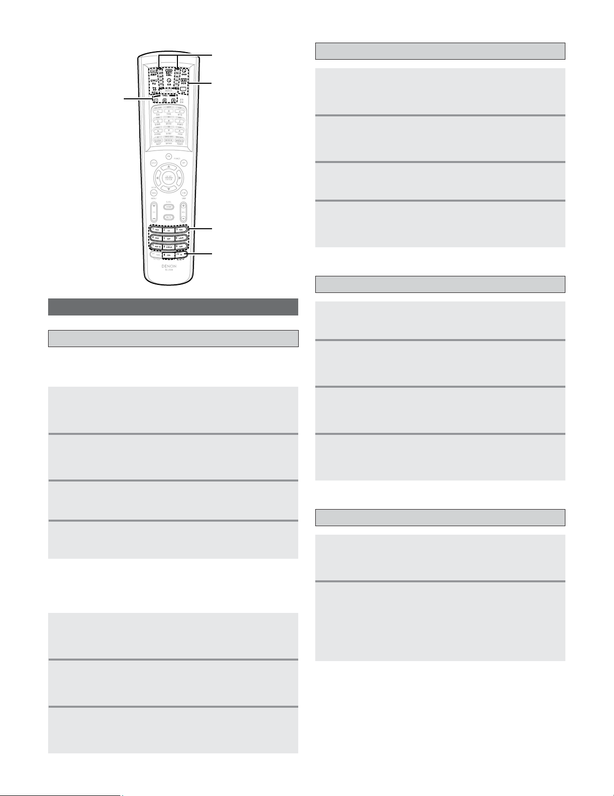
86
Advanced Operation
2
Resetting for individual buttons
1
2
Press and hold the RC SETUP button for at
least 3 seconds.
• The IR segment blinks twice.
Press the 9
, 7, 6
button (9
→→
7
→→
6) in that order.
• The IR segment blinks twice and the learning
function resetting mode is set.
Resetting the remote control unit
Resetting the learning function
3
Press the MODE SELECTOR button for the
device to be reset.
4
Press the button to be reset twice.
• The IR segment blinks twice.
1
2
3
Press the SYSTEM CALL button (1, 2 or 3) you
want to reset.
Press and hold the
RC SETUP button for at
least 3 seconds.
• The IR segment blinks twice.
Press the 9, 7, 8 button (9
→→
7
→→
8) in that order.
• The IR segment blinks twice and the system call
resetting mode is set.
4
Press and hold the RC SETUP button for at
least 3 seconds.
• The IR segment blinks twice.
Resetting the system call function
1
2
3
Press the 9, 8, 4 button (9
→→
8
→→
4) in that order.
• The IR segment blinks twice and the punch through
function resetting mode is set.
Press the MODE SELECTOR button for the
device to be reset (TV or SAT/CBL).
Press and hold the
RC SETUP button for at
least 3 seconds.
• The IR segment blinks twice.
4
Press and hold the RC SETUP button for at
least 3 seconds.
• The IR segment blinks twice.
Resetting the punch through function
1
2
Press the 9, 8, 1 button (9
→→
8
→→
1) in that order.
• The IR segment blinks 4 times and the learning
function resetting mode is set.
• Clear the entire system memory, which will restore
the remote control unit to the factory default
settings.
Press and hold the RC SETUP button for at
least 3 seconds.
• The IR segment blinks twice.
Resetting all the settings
2
Resetting for individual devices
1
2
Press and hold the RC SETUP button for at
least 3 seconds.
• The IR segment blinks twice.
Press the 9, 7, 6 button (9
→→
7
→→
6) in that order.
• The IR segment blinks twice and the learning
function resetting mode is set.
3
Press the MODE SELECTOR button for the
device to be reset twice.
• The IR segment blinks twice.
NUMBER
RC SETUP
IR segment
MODE SELECTOR
SYSTEM CALL

87
Advanced Operation
Multi zone music entertainment system
•When the outputs of the “ZONE2 (ZONE3, ZONE4)” OUT terminals are wired and connected to power amplifiers installed in
other rooms, different sources can be played in rooms other than the MAIN ZONE in which this unit and the playback devices
are installed. (Refer to ZONE2 (ZONE3, ZONE4) on the diagram below.)
• Settings can be made at “Power Amp Assign” in the “System Setup Menu” so that the same source as the ZONE2 (ZONE3,
ZONE4) pre-out terminals can be played from the speakers connected to the ZONE2 (ZONE3, ZONE4) speaker terminals
( page 129 ~ 133).
To control playback devices other than the ones above, either use that device’s remote control unit or preset a separately sold
programmable remote control unit.
• For the AUDIO output, use high quality pin-plug cords and wire in such a way that there is no humming or noise.
• For instructions on installation and operation of separately sold devices, refer to the devices’ operating instructions.
•Video signals are output from the ZONE3 video output terminals even when the power of ZONE3 is turned off.
ZONE2 playback
• The AVR-5805CI is equipped with pre-out terminals for which the volume is adjustable and video output terminals (composite,
S-Video and component) as the ZONE2 output terminals.
•A separately sold power amplifier or premain amplifier can be connected to enjoy ZONE2 playback.
• The AVR-5805CI ZONE2 monitor output is equipped with a video conversion function, so connect the ZONE2 monitor output
terminal with a video, S-Video or component video cable. For details, see “The video conversion function” ( page 28).
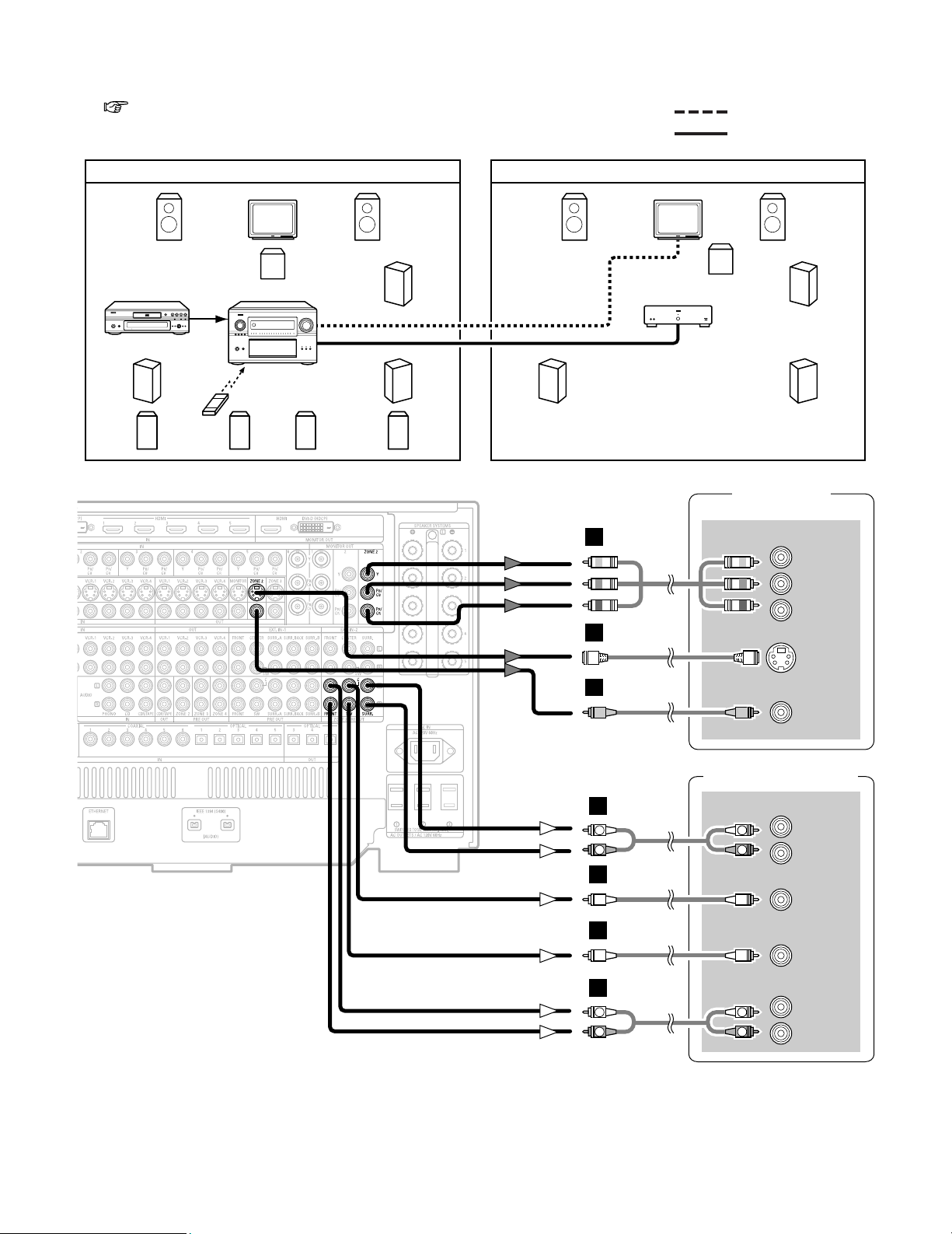
88
Advanced Operation
TV (Monitor)
S VIDEO
IN
VIDEO
IN
COMPONENT VIDEO IN
Y
P
B
PR
Power amplifier
R
SURROUND
L
R
FRONT
L
5.1ch AUDIO IN
CENTER
SUB-
WOOFER
H
I
J
B
B
R
L
R
L
A
R
L
R
L
A
2 ZONE2 5.1 channel system
• 5.1 channel playback is possible in ZONE2 if “5.1CH” is selected for the ZONE2 playback channel setting at “Channel Setup”
( page 126 ~ 128) in the System Setup Menu.
(Default setting of ZONE2 channel is “5.1CH”.)
AVR-5805CIDVD player
Input
Monitor
MAIN ZONE 9.1-channel system
ZONE2
AUDIO OUT
(VARIABLE OUT)
ZONE2
VIDEO OUT
SYSTEM REMOTE
CONTROL UNIT RC-1036
Power amplifier
Monitor
ZONE2 5.1-channel system
C
C
FL FR
SL
A
SW
SR
A
FL FR
SL
SW
SR
B
SB
R
SR
B
SB
L
SL
B
MULTI SOURCE AUDIO signal cable
ZONE2 VIDEO signal cable
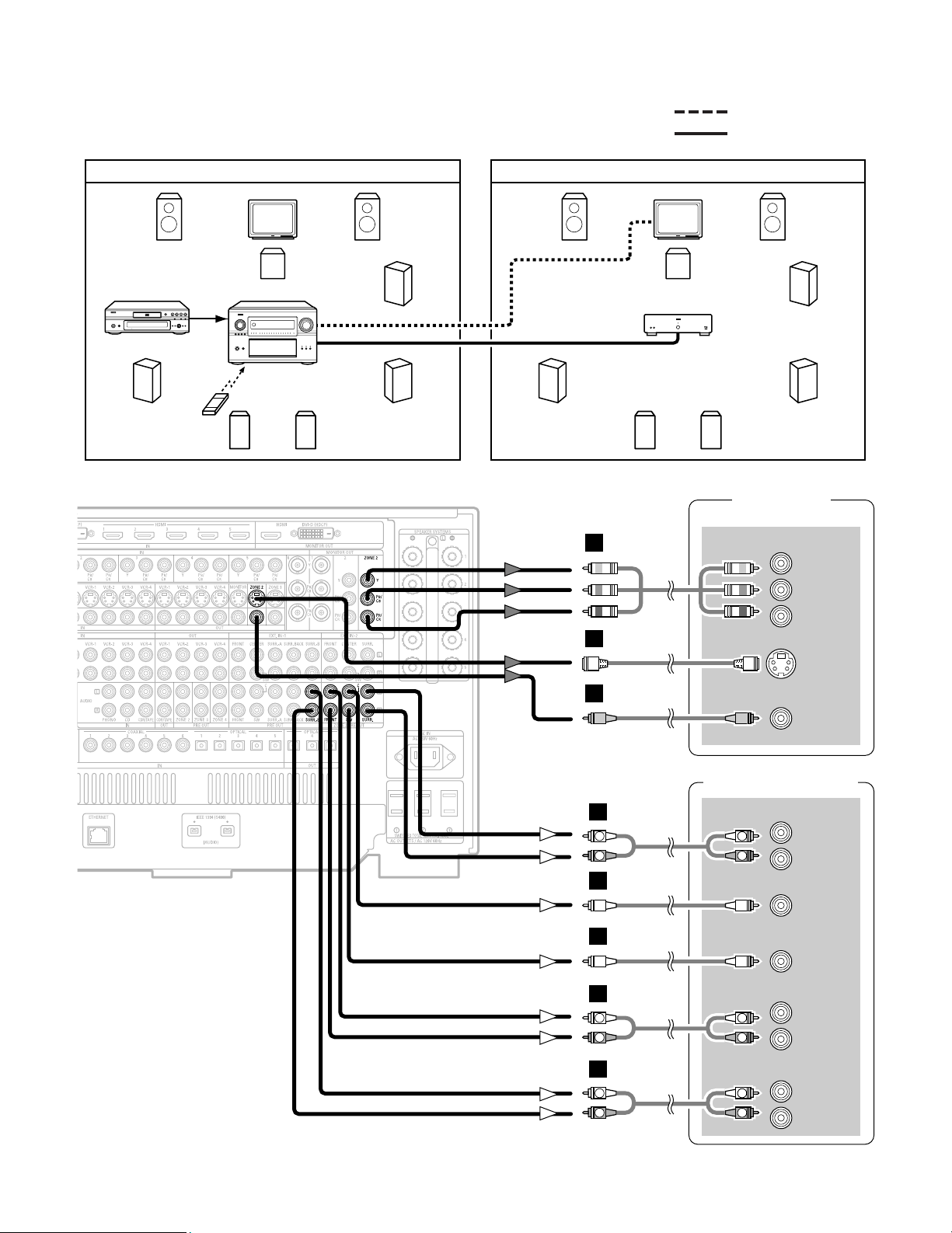
89
Advanced Operation
TV (Monitor)
S VIDEO
IN
VIDEO
IN
COMPONENT VIDEO IN
Y
P
B
PR
Power amplifier
R
SURROUND
L
R
FRONT
L
7.1ch AUDIO IN
CENTER
SUB-
WOOFER
R
SURROUND
BACK
L
H
I
J
R
L
R
L
B
A
B
R
L
R
L
A
R
L
R
L
A
MULTI SOURCE AUDIO signal cable
ZONE2 VIDEO signal cable
AVR-5805CIDVD player
Input
Monitor
MAIN ZONE 7.1-channel system
ZONE2
AUDIO OUT
(VARIABLE OUT)
ZONE2
VIDEO OUT
SYSTEM REMOTE
CONTROL UNIT RC-1036
Power amplifier
Monitor
ZONE2 7.1-channel system
C C
FL FR
SL
SW
SR
FL FR
SL
SW
SR
B
SB
R
SB
L
SB
R
SB
L
2 ZONE2 7.1 channel system
• 7.1 channel playback is possible in ZONE2 if “7.1CH” is
selected for the ZONE2 channel setting at “Channel
Setup” in the System Setup Menu.
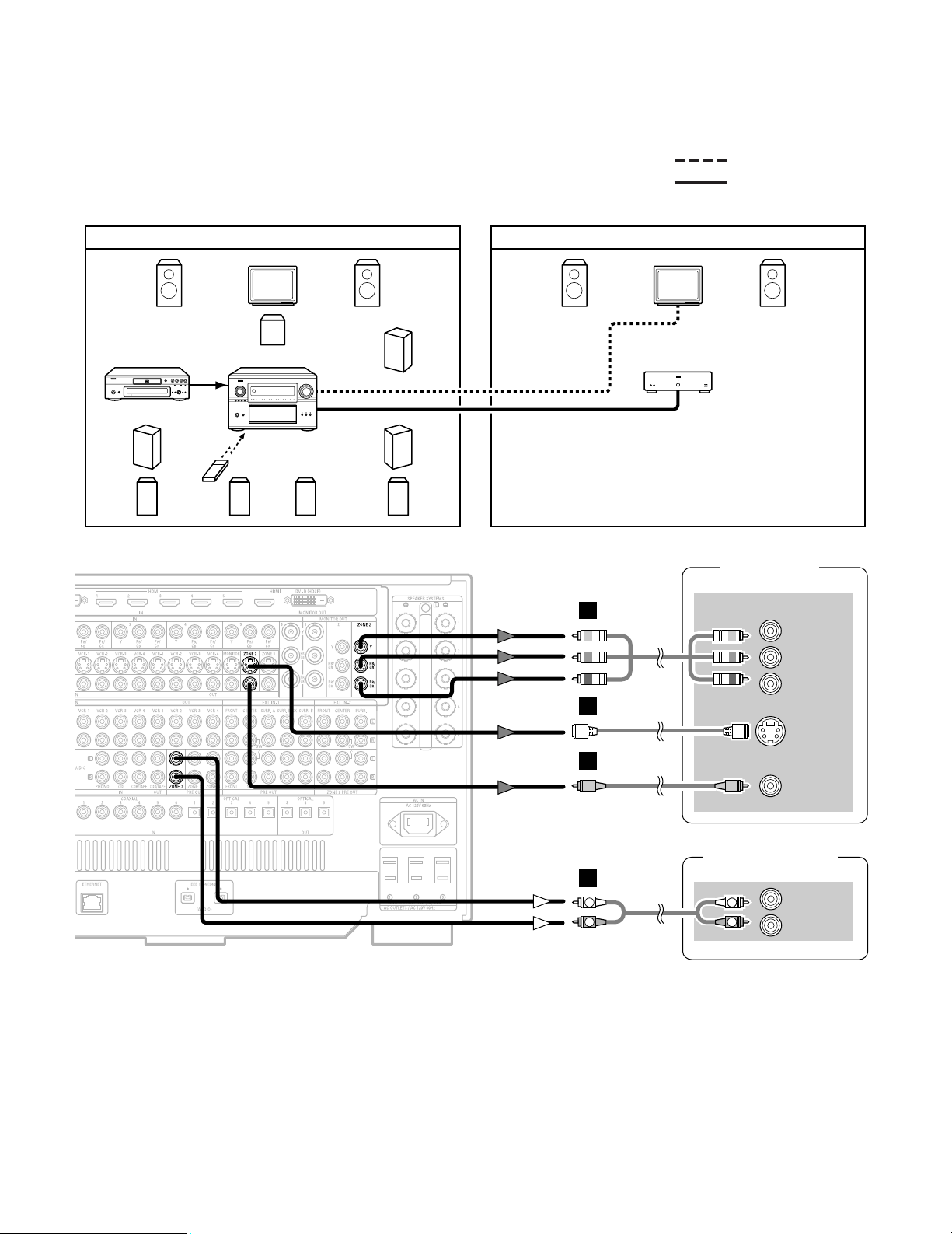
90
Advanced Operation
AVR-5805CIDVD player
Input
Monitor
MAIN ZONE 9.1-channel system
ZONE2 AUDIO OUT
(VARIABLE OUT)
ZONE2
VIDEO OUT
SYSTEM REMOTE
CONTROL UNIT RC-1036
Power amplifier
Monitor
ZONE2 STEREO/MONO system
C
FL FR
SL
A
SW
SR
A
FL FR
B
SB
R
SR
B
SB
L
SL
B
MULTI SOURCE AUDIO signal cable
ZONE2 VIDEO signal cable
2 ZONE2 STEREO/MONO system
• When two speakers are being used in ZONE2, select “STEREO” for the ZONE2 channel setting at “Channel Setup” in the
System Setup Menu. Stereo sound can be enjoyed in ZONE2.
• When only one speaker is being used in ZONE2, select “MONO” for the ZONE2 channel setting at “Channel Setup” in the
System Setup Menu. In this case, monaural sound can be enjoyed in ZONE2.
TV (Monitor)
S VIDEO
IN
VIDEO
IN
COMPONENT VIDEO IN
Y
P
B
PR
Power amplifier
R
L
IN
H
I
J
R
L
R
L
A
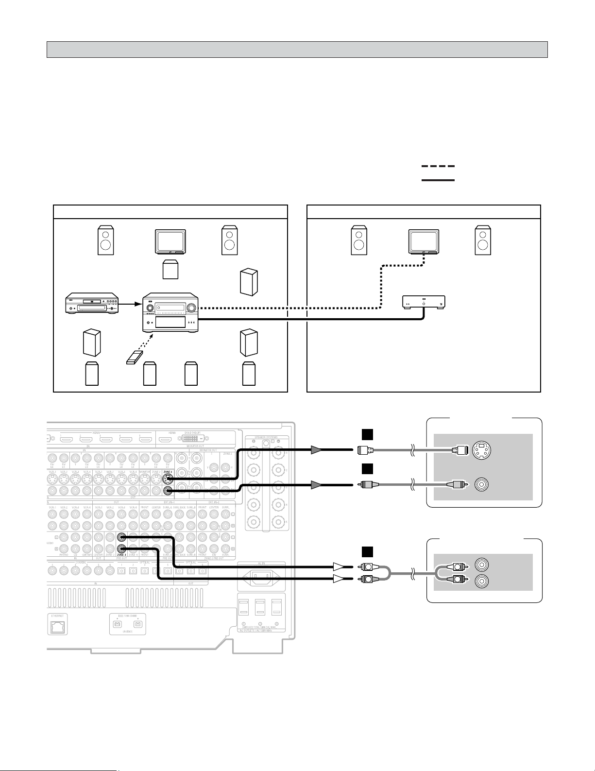
91
Advanced Operation
ZONE3 playback
• The AVR-5805CI is equipped with pre-out terminals for which the volume is adjustable and video output terminals (composite
and S-Video) as the ZONE3 output terminals.
• When using a monitor in ZONE3, the input device’s cable type must be the same as the type of cable connected to the AVR-
5805CI’s ZONE3 monitor output terminal (video or S-Video).
AVR-5805CIDVD player
Input
Monitor
MAIN ZONE 9.1-channel system
ZONE3 AUDIO OUT
(VARIABLE OUT)
ZONE3
VIDEO OUT
SYSTEM REMOTE
CONTROL UNIT RC-1036
Power amplifier
Monitor
ZONE3 STEREO/MONO system
C
FL FR
SL
A
SW
SR
A
FL FR
B
SB
R
SR
B
SB
L
SL
B
MULTI SOURCE AUDIO signal cable
ZONE3 VIDEO signal cable
2 ZONE3 STEREO/MONO system
•Stereo and monaural sound can be enjoyed in ZONE3. (By default, “STEREO” is selected.)
• When only one speaker is being used in ZONE3, select “MONO” for the ZONE3 channel setting at “Channel Setup” in the
System Setup Menu.
TV (Monitor)
S VIDEO
IN
VIDEO
IN
Power amplifier
R
L
IN
H
I
R
L
R
L
A
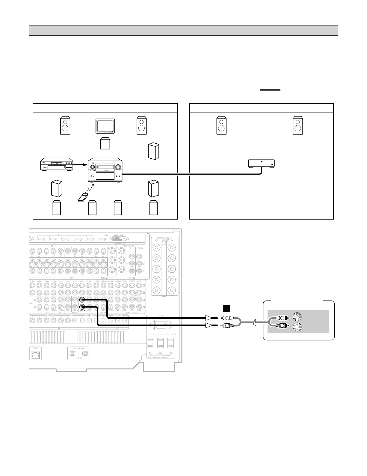
92
Advanced Operation
ZONE4 playback
• The AVR-5805CI is equipped with pre-out terminals for which the volume is adjustable as the ZONE4 output terminals.
AVR-5805CIDVD player
Input
Monitor
MAIN ZONE 9.1-channel system
ZONE4 AUDIO OUT
(VARIABLE OUT)
SYSTEM REMOTE
CONTROL UNIT RC-1036
Power amplifier
ZONE4 STEREO/MONO system
C
FL FR
SL
A
SW
SR
A
FL FR
B
SB
R
SR
B
SB
L
SL
B
MULTI SOURCE AUDIO signal cable
2 ZONE4 STEREO/MONO system
•Stereo and monaural sound can be enjoyed in ZONE4. (By default, “STEREO” is selected.)
• When only one speaker is being used in ZONE4, select “MONO” for the ZONE4 channel setting at “Channel Setup” in the
System Setup Menu.
Power amplifier
R
L
IN
R
L
R
L
A
93
Advanced Operation
ZONE2 SELECT
ZONE3/4/REC SELECT
FUNCTION
1
Press the ZONE2 SELECT button to display the
“ZONE2 SOURCE” on the display.
2
Turn the FUNCTION knob to select the source
you want to output appears on the display.
3
Start playing the source to be output.
For operating instructions, refer to the manuals of the
respective components.
• The signals of the source selected in the ZONE3 mode are
also output from the VCR-1, VCR-2, VCR-3, VCR-4 and
CDR/TAPE recording output terminals.
• Digital signals are not output from the ZONE3 and ZONE4
audio output terminals.
• About the MULTI ZONE connections ( page 88 ~ 92).
Outputting a program source to an
amplifier, etc., in a ZONE2 room
(ZONE2 SELECT mode)
1
Press the ZONE3/4/REC SELECT button to
display the “ZONE3 (ZONE4) SOURCE” on
the display.
• If the “ZONE3 SOURCE” is selected, the MULTI
indicator light.
The display switches as follows each time the button
is pressed.
2
Turn the FUNCTION knob to select the source
you want to output appears on the display.
ZONE4
ZONE3
(REC OUT)
3
Start playing the source to be output.
For operating instructions, refer to the manuals of the
respective components.
Outputting a program source to an
amplifier, etc., in a ZONE3 or ZONE4 room
(ZONE3, ZONE4 SELECT mode)
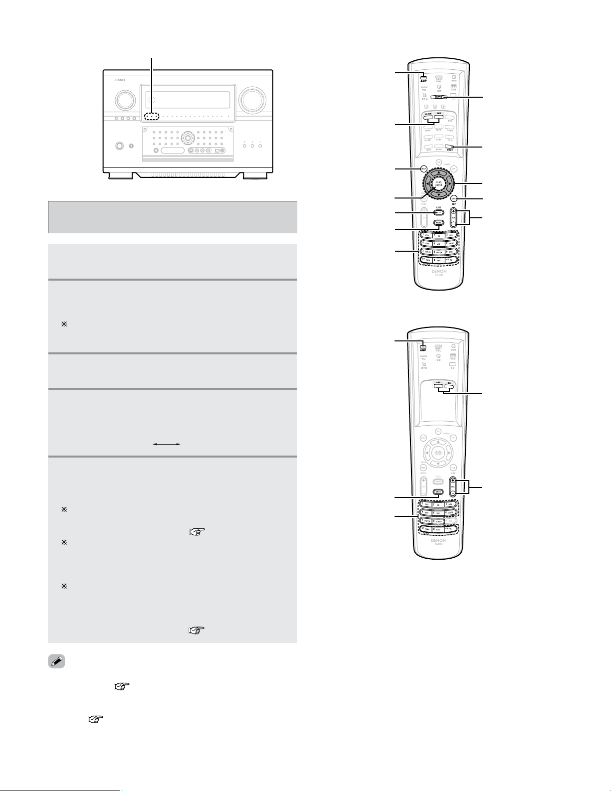
Advanced Operation
94
4
Select the input mode. (only ZONE2 mode):
Press the
INPUT MODE button to switch to the
input.
Remote control unit operations during
multi-source playback
1
Select the zone which you want to operate
pressing the
AMP buttons.
2
Press the ON button to turn on the Zone power.
• The multi zone power indicator light.
Press the OFF button to turn off the zone power.
The multi zone power indicator on main unit is off.
AUTO ANALOG
5
The volume of the outputs of the different
zones can be adjusted with the
VOLUME
button on the remote control unit.
The output level can be controlled only if the zone
volume level is set “variable” at “Volume Control” in
the “System Setup Menu” ( page 134).
Default volume setting
ZONE2 : –40 dB
ZONE3 : –40 dB
ZONE4 : –40 dB
The Zone volume can be adjusted within the range of
–80 to 18 dB, in steps of 1 dB.
However, when using with ZONE2 set to multi-channel
(5.1 or 7.1 channel), the ZONE2 volume can be
adjusted in steps of 0.5 dB ( page 126 ~ 128).
• The MUTE button can be operated in the same way as for the
MAIN ZONE ( page 45).
• In the ZONE2 mode, the VIDEO SELECT and ON SCREEN
buttons can be operated in the same way as for the MAIN
ZONE ( page 45, 46).
Multi zone power indicators
AMP
ON/OFF
MUTE
VOLUME
ON SCREEN
INPUT MODE
VIDEO SELET
SYSTEM SETUP
CURSOR
TEST TONE
CH SEL/ENTER
FUNCTION
AMP
ON/OFF
FUNCTION
MUTE
VOLUME
3
Press the FUNCTION button to select the input
function you wish to operate.
(ZONE2)
(ZONE3/4)
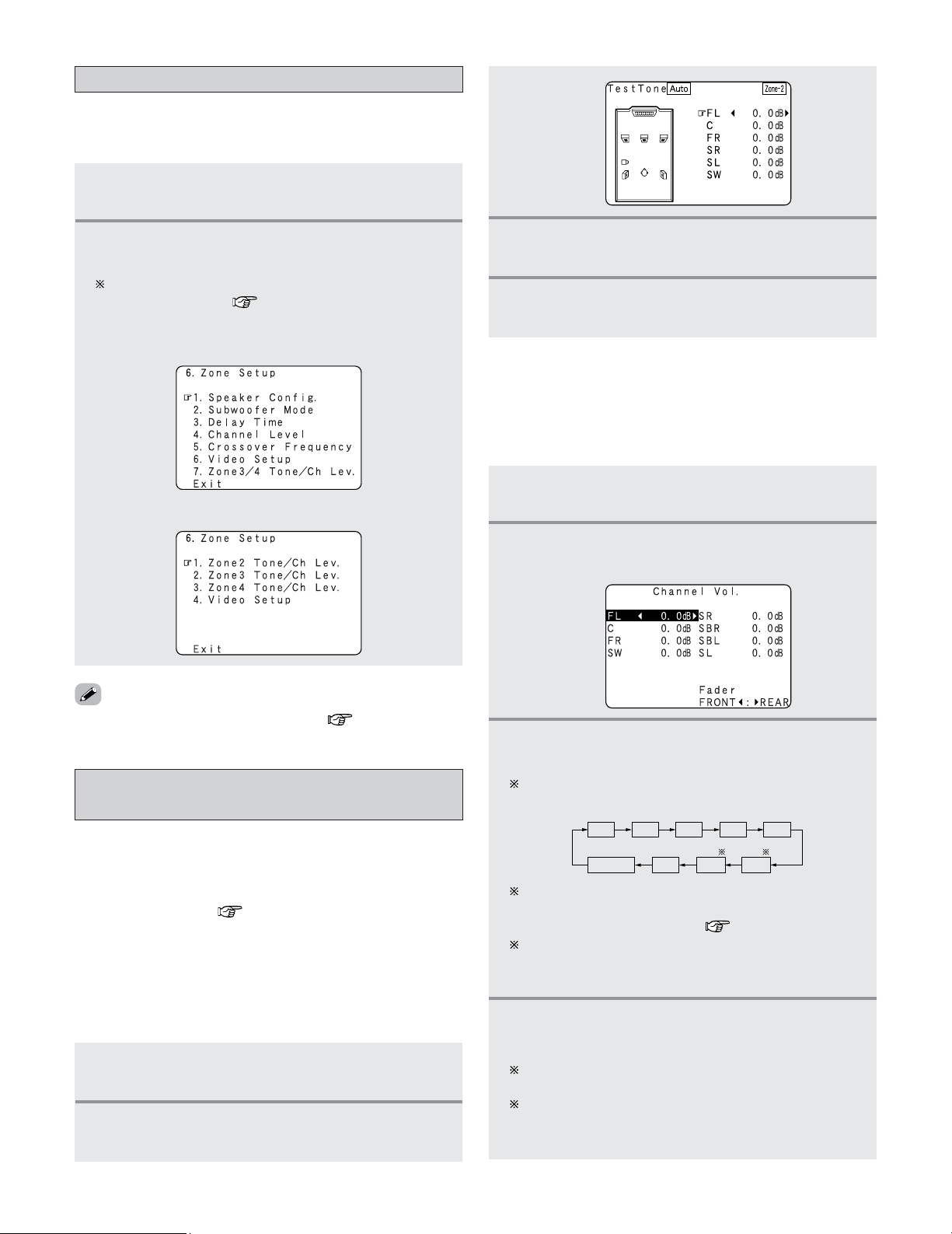
95
Advanced Operation
1
Select the ZONE2 mode using the AMP
button.
Adjustment steps that need to be performed
prior to surround sound playback in ZONE2
2 Test Tone
• Before playing with the surround function, be sure to use
the test tones to adjust the playback level from the
different speakers. This adjustment can be performed with
the system setup ( page 122, 123) or from the remote
control unit, as described below.
• Adjusting with the remote control unit using the test tones
is only possible in the “Auto” mode and only effective in
the STANDARD (DOLBY/DTS SURROUND) modes. The
adjusted levels for the different modes are automatically
stored in the memory.
1
Select the ZONE2 mode using the AMP
button.
2
Press the CH SEL/ENTER button.
• The “Channel Vol.” screen appears.
2 Channel Level
• After adjusting using the test tones, adjust the channel
levels either according to the playback sources or to suit
your tastes, as described below.
3
Press the CURSOR
DD
,
HH
or CH SEL/ENTER
button to select the speaker.
The channel switches as shown below each time the
CH SEL/ENTER button is pressed.
4
Press the CURSOR
FF
or
GG
button to adjust the
level.
The adjustment range for the different channels is
+12.0 dB to –12.0 dB.
The sound from the subwoofer can be completely cut
by lowering the SW (subwoofer) setting one additional
step from –12.0 dB (setting it to “OFF”).
FADER
SR
SBL
SL
SBR
FL
C
FR
SW
ZONE2 surround back speakers are only displayed when
“7.1ch” is selected for the ZONE2 channel output
setting at “Channel Setup” ( page 126 ~ 128).
When the ZONE2 surround back speaker setting is set
to “1spkr” for “Speaker Configuration”, this is set to
“SB”.
• For instructions on making the settings ( page 120 ~ 125).
1
Select the ZONE2 mode using the AMP
button.
2
Press the SYSTEM SETUP button.
• The ZONE2 system setup menu appears.
The screen displayed depends on the settings made at
“Channel Setup” ( page 126 ~ 128).
System setup for multi-zone
• This makes possible to make the optimum setting for the
speaker systems used in ZONE2.
3
Press the CURSOR
FF
or
GG
button to adjust all
the speakers to the same volume.
4
After completing the adjustment, press the
TEST TONE button again.
Example: When “ZONE2” is set for a 5.1 or 7.1 channel
system
Example: When “ZONE2” is set for a STEREO or MONO
2
Press the TEST TONE button.
• The “Test Tone” screen appears.
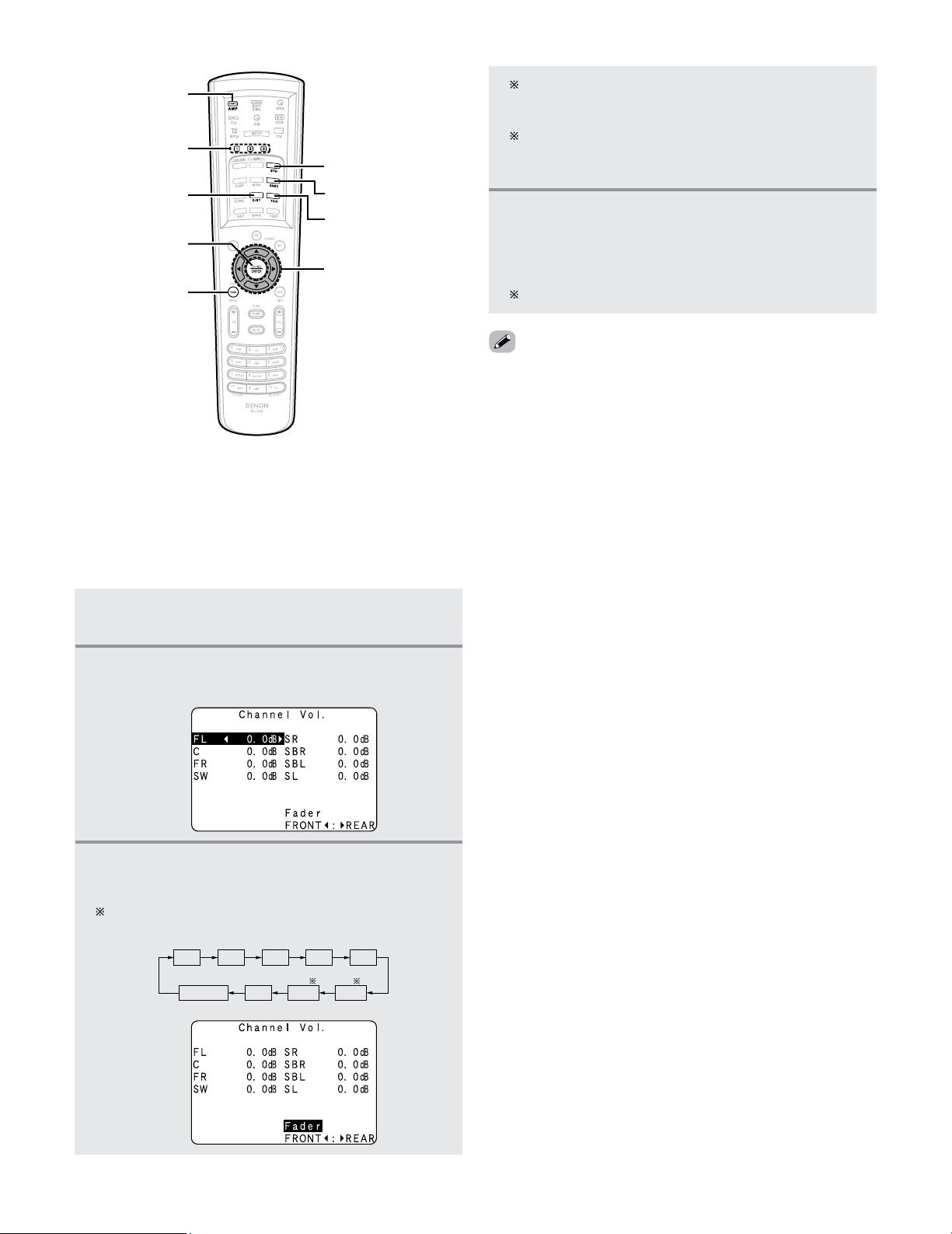
96
Advanced Operation
1
Select the ZONE2 mode using the AMP
button.
2
Press the CH SEL/ENTER button.
• The “Channel Vol.” screen appears.
3
Press the CURSOR
DD
,
HH
or CH SEL/ENTER
button then select “Fader”.
The channel switches in the order shown below each
time the CH SEL/ENTER button is pressed.
FADER
SR
SBL
SL
SBR
FL
C
FR
SW
2
Fader function
• This function makes it possible to lower the volume of the
front channels (FL, C and FR) or the rear channels (SL, SR,
SBL and SBR) of ZONE2 together. Use it for example to
adjust the balance of the sound from each position when
multi-channel music sources are played.
DSP SIMULATION
STANDARD
7CH STEREO
CURSOR
SURROUND
PARAMETER
USER MODE
STEREO
CH SEL/ENTER
AMP
4
Press the CURSOR
FF
button to reduce the
volume of the front channels, the
CURSOR
GG
button to reduce the volume of the rear
channels.
The fader function does not affect the SW channel.
ZONE2 surround back speakers are only displayed
when “7.1ch” is selected for the ZONE2 channel
output setting at “Channel Setup”.
When the ZONE2 surround back speaker setting is set
to “1spkr” for “Speaker Configuration”, this is set to
“SB”.
• The channel whose channel level is adjusted lowest can be
faded to –12.0 dB using the fader function.
• If the channel levels are adjusted separately after adjusting
the fader, the fader adjustment values are cleared, so adjust
the fader again.

97
Advanced Operation
2
Select the ZONE2 mode using the AMP
button.
3
Press and hold the USER MODE button until
the “USER 1 (2 or 3) MEMORY” is appears
on the ZONE2 monitor.
USER MODE function of ZONE2
• The AVR-5805CI is equipped with a function for storing the
input source, auto surround mode and input mode settings
selected for the MAIN ZONE and ZONE2 in the memory so
they can be used whenever desired.
• For ZONE2, three patterns of settings can be stored in the
memory using the USER MODE 1, 2 and 3 buttons on the
Remote control unit.
• See page 60 for a description of the MAIN ZONE’s “USER
MODE” function.
1
Set the following to the desired status:
q ZONE2 input source
w ZONE2 auto surround mode
e ZONE2 input mode
2 Storing the settings in the memory
1
Select the ZONE2 mode using the AMP
button.
2
Press the USER MODE button at which the
settings you want to call out are stored.
2 Calling the settings out
1
Select the ZONE2 mode using the AMP
button.
2
Select the surround mode for each input
channel.
ZONE2 Surround
• When ZONE2 is used with a 5.1 or 7.1 channel system,
various surround modes can be selected according to the
program source being played.
• The desired sound field can be achieved by adjusting the
parameters for the various surround modes.
(Remote control unit)
The surround mode switches in the following order
each time the DSP SIMULATION button is pressed.
WIDE SCREEN
JAZZ CLUB
SUPER STADIUM
ROCK ARENA
MATRIX
VIRTUAL
VIDEO GAME
CLASSIC CONCERT
MONO MOVIE
4
Press the CURSOR
DD
or
HH
button to select the
various surround parameters.
6
Press the ENTER or SURROUND PARAMETER
button to complete the setting.
5
Press the CURSOR
FF
or
GG
button to adjust the
parameters setting.
See pages 49, 54 ~ 58, 61 for a description of the
features of the various surround modes.
The following surround modes can be selected in
ZONE2: STEREO, STANDARD (DOLBY/DTS
SURROUND), 5/7CH STEREO, WIDE SCREEN, SUPER
STADIUM, ROCK ARENA, JAZZ CLUB, CLASSIC
CONCERT, MONO MOVIE, VIDEO GAME, MATRIX
and VIRTUAL.
3
Press the SURROUND PARAMETER button.
• The surround parameter menu appears.
q STANDARD (Dolby
Digital/DTS Surround)
mode.
w DSP surround
simulation mode.
(Remote control unit)
(Remote control unit)
e STEREO mode.
r 5CH/7CH STEREO
mode.
(Remote control unit)
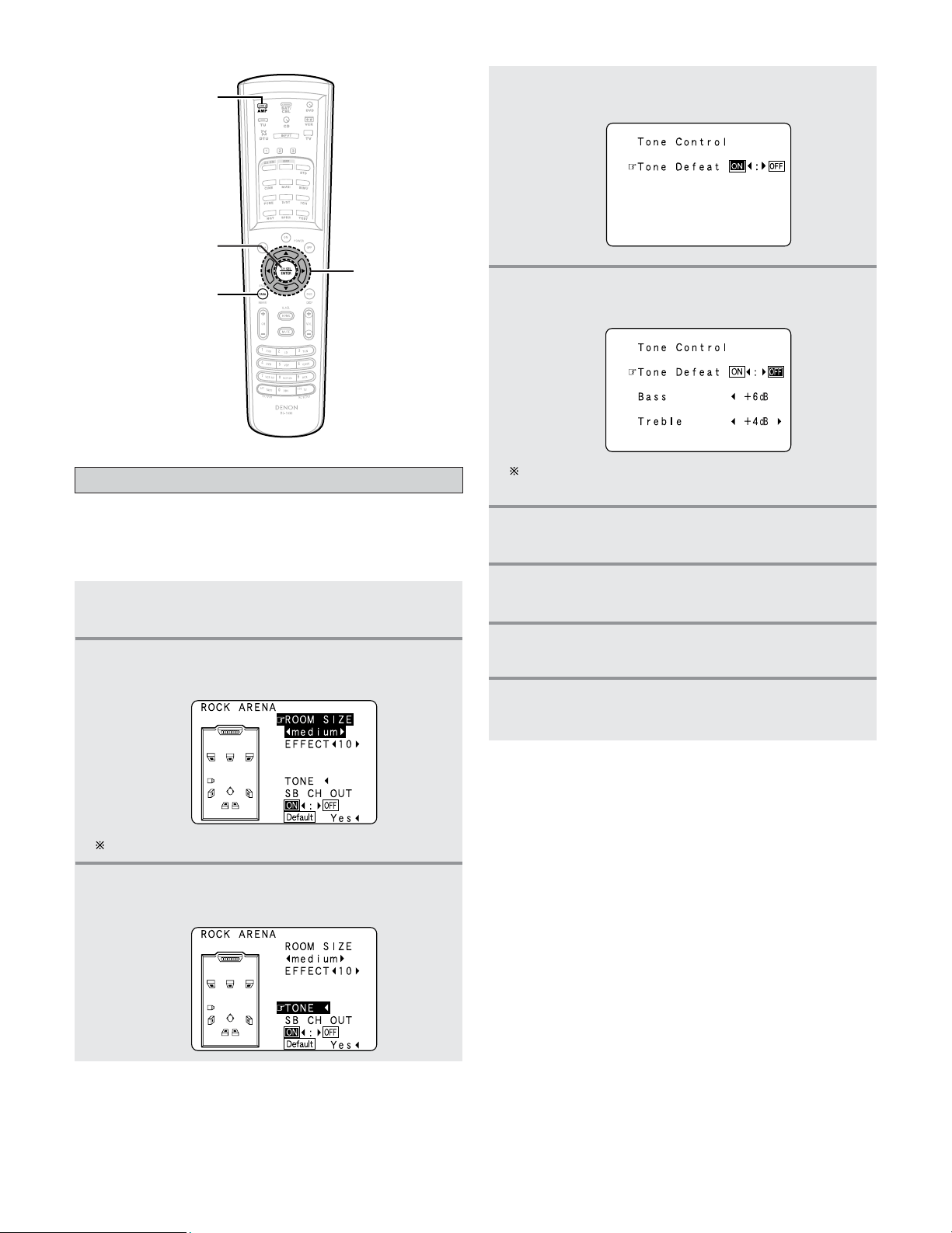
98
Advanced Operation
1
Select the ZONE2 mode using the AMP
button.
2
Press the SURROUND PARAMETER button.
• The surround parameter menu appears.
ZONE2 tone control setting
• This function allows you to adjust the bass and treble of the
ZONE2 audio output during surround playback in ZONE2 to
suit your tastes.
3
Press the CURSOR
DD
or
HH
button to select
“TONE”.
The screen selected surround mode appears.
4
Press the CURSOR
FF
button.
• Switch to the “Tone Control” screen.
CURSOR
ENTER
SURROUND
PARAMETER
AMP
5
Press the CURSOR
GG
button to select “Tone
Defeat OFF”.
If you do not want to the tone to be adjusted, set
“Tone Defeat” to “ON”.
6
Press the CURSOR
DD
or
HH
button to select
“Bass” or “Treble”.
7
Press the CURSOR
FF
or
GG
button to set the
level.
8
Press the ENTER button.
• The surround parameter menu reappears.
9
Press the ENTER or SURROUND PARAMETER
button to complete the setting.
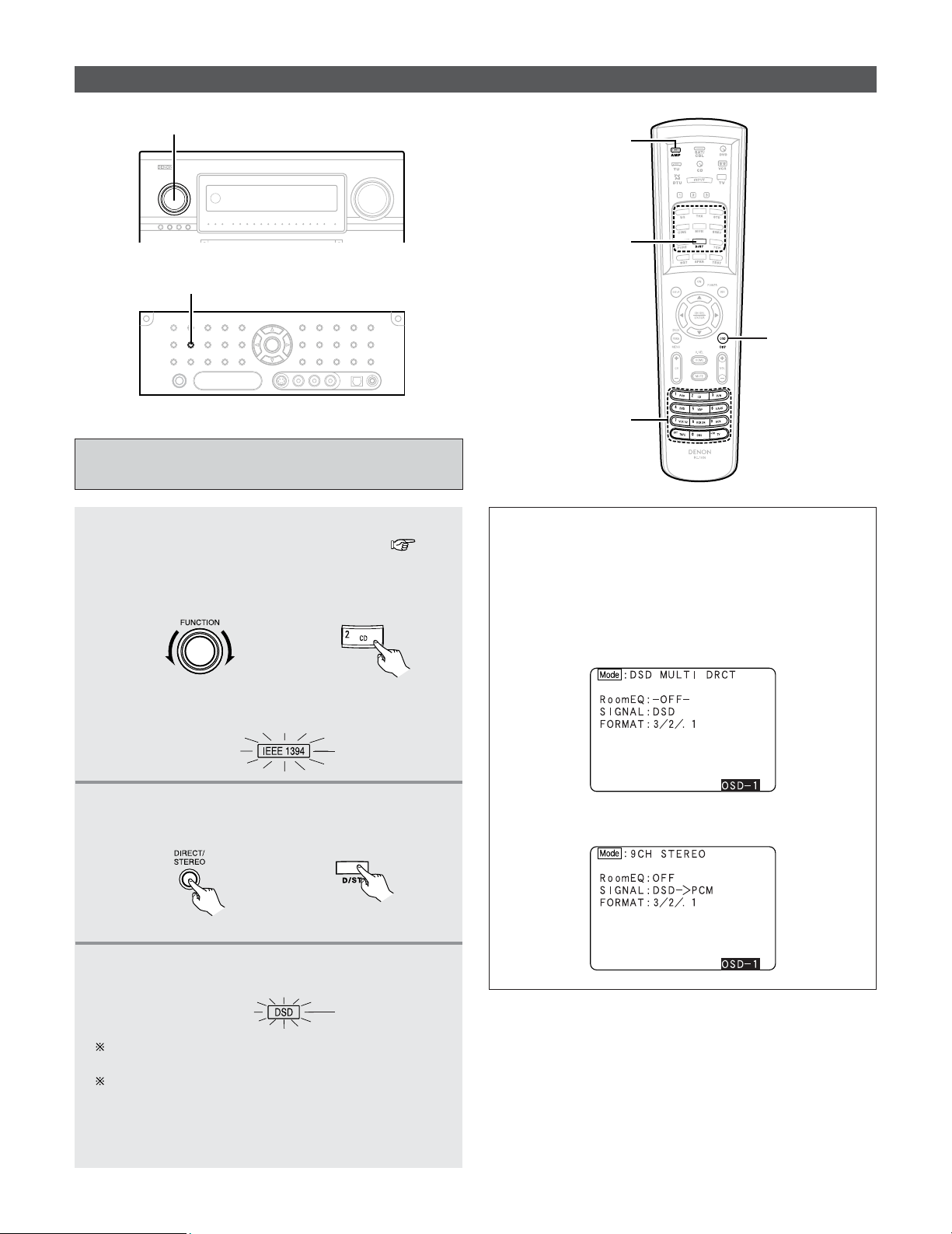
Advanced Operation
99
Other function
Playing Super Audio CDs with an IEEE1394
cable
1
Select the input source to which IEEE1394 was
assigned at the “IEEE1394 Assign” ( page
107) in the system setup.
Example: CD
(Main unit) (Remote control unit)
• The IEEE1394 indicator lights.
Lights
2
Select the surround mode.
Example: DIRECT
(Main unit) (Remote control unit)
3
Start playback on the selected component.
• The DSD indicator lights.
Lights
For operating instructions, refer to the component’s
manual.
“DSD DIRECT” is shown on the display when playing
DSD 2 channel signals in the DIRECT mode. “DSD
MULTI DIRECT” is displayed when playing DSD multi-
channel signals in the DIRECT mode (SB CH OUT
“OFF”).
When playing DSD signals in the DIRECT or PURE DIRECT
mode, the DSD signals are converted into analog signals.
When playing in other surround modes, the DSD signals are
first converted into PCM signals. The input signal and
playing status can be checked by pressing the ON SCREEN
button on the remote control unit.
Example: When DSD multi-channel signals are played in
the DIRECT mode
Example: When DSD multi-channel signals are played in
the 9CH STEREO mode
FUNCTION
DIRECT/STEREO
ON SCREEN
DIRECT/STEREO
FUNCTION
AMP
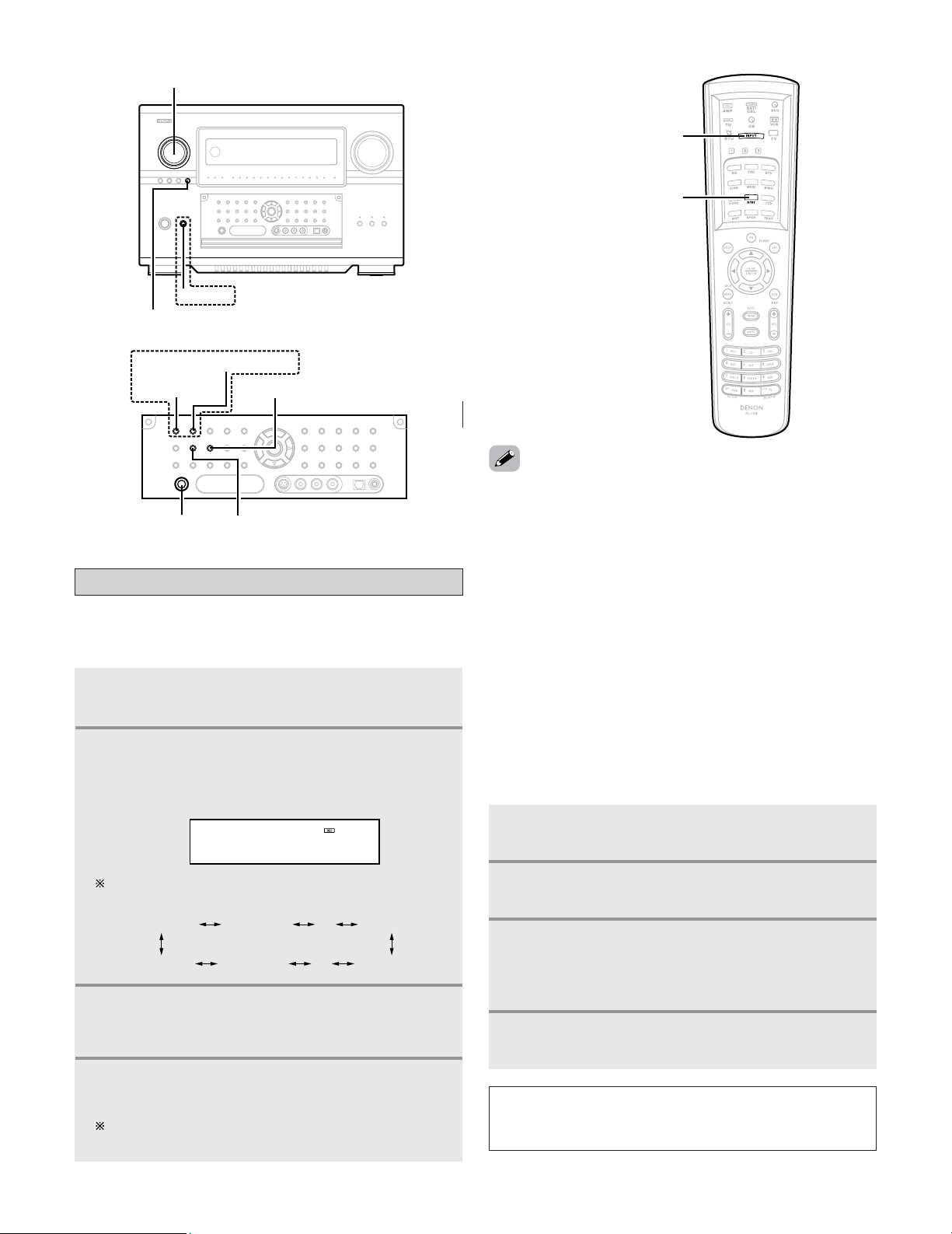
100
Advanced Operation
1
Press the ZONE3/4/REC SELECT button until
“ZONE3 SOURCE” appears on the display.
2
With “ZONE3 SOURCE” displayed, turn the
FUNCTION knob until “RECOUT SOURCE”
appears on the display.
• The REC indicator lights.
RECOUT SOURCE
DVD
2
Playing one source while recording another
(REC OUT mode)
2
Recording Dolby Digital and DTS multi channel
sources
•With this set it is possible to record Dolby Digital and DTS
multichannel signals converted into 2 channel analog
signals.
• The recording signals are output to the TAPE and VCR
output terminals.
• Down-mixed analog signals converted into digital signals
are output from the OPTICAL 3, 4 and 5 digital output
terminals at this time.
1
Press the ZONE3/4/REC SELECT button until
“RECOUT SOURCE” appears on the display.
2
Press the INPUT MODE button to set the input
mode according to the source to be played.
3
Press the DIRECT/STEREO button to set the
surround mode.
• The multichannel digital signals are down-mixed and
output to the TAPE and VCR output terminals.
4
Set the recording mode.
•To cancel, turn the FUNCTION knob and select “SOURCE”.
• Recording sources other than digital inputs selected in the
REC OUT mode are also output from the ZONE3 audio/video
terminals.
• When the REC OUT mode is selected, the ZONE3 button on
the remote control unit cannot be operated.
ZONE3 SOURCE ZONE3 TUNER
····
····
ZONE3 V.AUX
RECOUT SOURCERECOUT VCR-4RECOUT V.AUX
The function switches as shown below when the
FUNCTION knob is turned.
3
With “RECOUT SOURCE” displayed, turn
the
FUNCTION knob to select the source you
wish to record.
4
Set the recording mode.
• Start recording.
For operating instructions, refer to the manual of the
component on which you want to record.
NOTE:
• This function does not work when “5.2 ch / 5.3 ch” is set
for the MAIN ZONE’s channel setup.
INPUT MODE
DIRECT/STEREO
ZONE3/4/REC SELECT
POWER
FUNCTION
PHONES
STANDARD INPUTMODE
HOME THX CINEMA
DIRECT/STEREO
Multi-source recording / playback
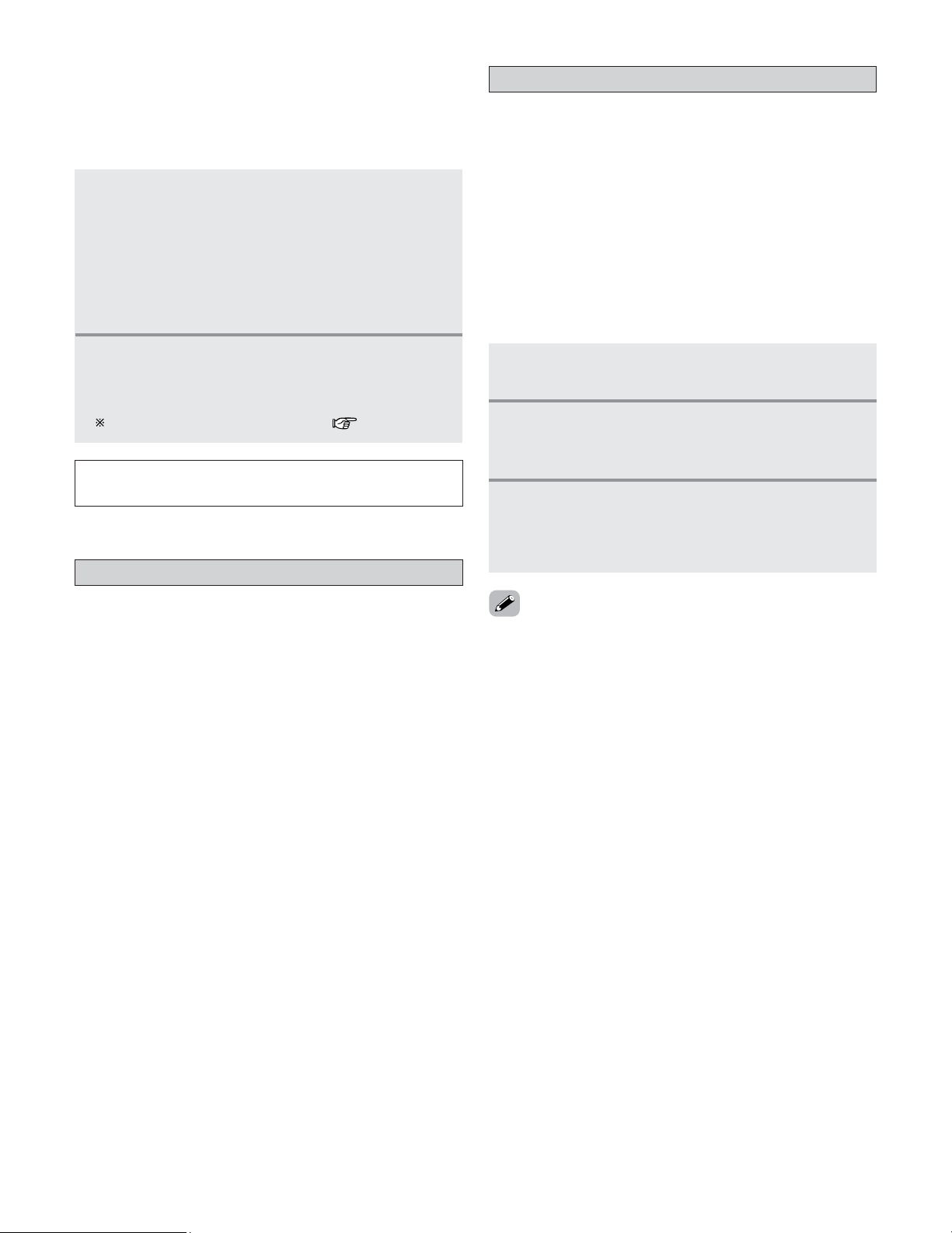
101
Advanced Operation
Initialization of the Microprocessor
• In very rare instances, the AVR-5805CI internal microprocessor
might lock up, or otherwise cause mis-operation. This might
be caused due to an AC line surge or line spike noise, or by
static electric discharge on or nearby the unit, or to
connected components. If the condition cannot be corrected
by powering off the unit, including disconnection of the
power supply cord for a period of ten minutes and
subsequent re-connection, then the unit may have to be re-
initialized. Doing so will restore the microprocessor to its
original out-of-the-box state, with all custom memories and
settings erased, and the original factory default settings
restored. Only use this procedure if you are sure that the
microprocessor requires re-initialization.
1
Switch off the unit using the main unit’s
POWER switch.
2
Hold the following STANDARD button and
HOME THX CINEMA button, and turn the
main unit’s
POWER switch on.
3
Check that the entire display is flashing with
an interval of about 1 second, and release your
fingers from the 2 buttons.
• The microprocessor will be initialized.
• If step 3 does not work, start over from step 1.
•If the microprocessor has been reset, all the settings are
reset to the default values (the values set upon shipment
from the factory).
Last Function Memory
• This unit is equipped with a last function memory which
stores the input and output setting conditions as they were
immediately before the power is switched off.
This function eliminates the need to perform complicated
resetting when the power is switched on.
• The unit is also equipped with a back-up memory. This
function provides approximately one week of memory
storage from when the main unit’s power switch is off and
with the power supply cord disconnected.
1
The Dolby Headphone play mode is set when
headphones are connected to the
PHONES jack
during playback in the STANDARD
(DOLBY/DTS Surround) mode.
• When this is done, signals encoded in the Dolby
Headphone mode are automatically output from the
recording output terminals (analog and digital) and
can be recorded.
2
Select the parameters and set the desired
mode.
• Start recording.
Refer to the “Dolby Headphone” ( page 59).
NOTE:
• Do not disconnect the headphones during recording.
2
Dolby Headphone recording
• When REC OUT mode is set to “SOURCE”, with the AVR-
5805CI it is possible to output signals encoded in the Dolby
Headphone mode from the recording output terminal and
record them on a separate recorder.
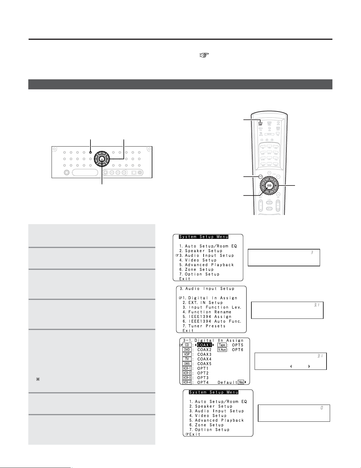
102
Navigating through the System Setup Menu
Audio In Setup
*System Setup
•You can change setting using the buttons on the front panel or remote control unit.
[ On screen display ] [ Display ]
3
4
5
7
Digital In
*Audio In Setup
CD : COAX1
*Digital In
Exit
*System Setup
2
Press the SYSTEM SETUP button.
• The “System Setup Menu” appears.
3
Press the CURSOR
DD
or
HH
button
to
select the item you want to set, then press
ENTER button.
4
Press the CURSOR
DD
or
HH
again to select
the item you want to set, then press ENTER
button.
5
To change the setting:
Press
CURSOR
DD
or
HH
button to select
the item you want to change, then press
CURSOR
FF
or
GG
button to change the
setting.
Select “Default Yes”, then press the CURSOR
FF
button to reset to the default setting.
6
Press the ENTER button and set a new
item.
7
Press the SYSTEM SETUP button to
return to the “System Setup Menu” or
the main menu.
AMP
SYSTEM SETUP
ENTER
CURSOR
SYSTEM SETUP
ENTER
CURSOR
•You can customize a variety of system setup so that it may be fitting for your listening environment.
For the contents of a system menu and the initial setting of this unit ( page 153 ~ 156).
1
Press the AMP button to select the
“AMP” mode.
Advanced Setup – Part 1
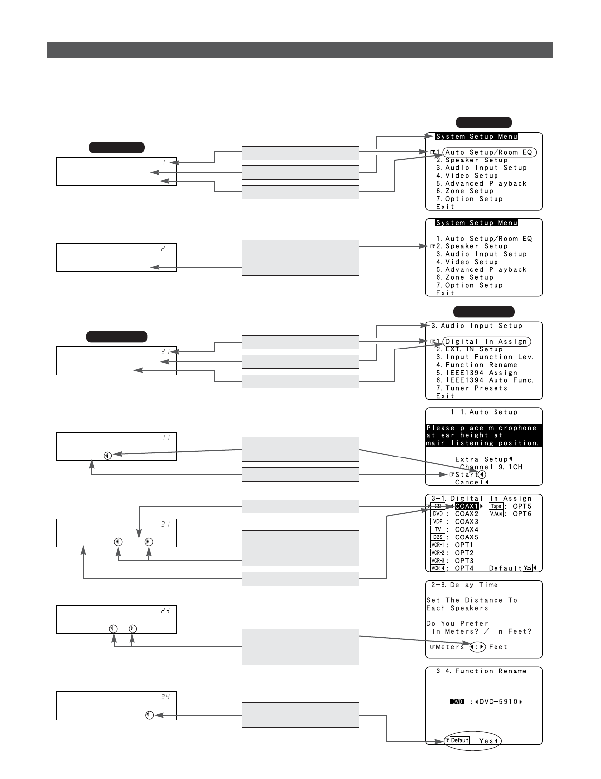
103
Advanced Setup – Part 1
• The AVR-5805CI is equipped with an intuitive and easy-to-understand on screen display, and is equipped with an alpha-numeric
front panel display tube that can also be used to check and adjust settings. We recommend that you use the on screen display
when you make system adjustments. Some representative front panel and on screen display examples are shown below.
[ Front display ]
[ On screen display ]
Auto Set/RoomEQ
*System Setup
Speaker Setup
*System Setup
Digital In
*Audio In Setup
Start
*Auto Setup
CD : COAX1
*Digital In
Meters : Feet
*Delay Time
Default : Yes
Rename DVD
Top menu
Top menu
Main menu
Main menu
No.
Screen title
Sub-menu title
To select a menu, press the
CURSOR
DD
or
HH
button.
Press the CURSOR
FF
button
to execute.
Currently selected line
Current setting
The settings are changed
with the CURSOR
FF
or
GG
button.
Currently selected line
Select either one pressing
the CURSOR
FF
or
GG
button.
Press the CURSOR
FF
button
to select “Default”.
No.
Screen title
Sub-menu title
On screen display and front display
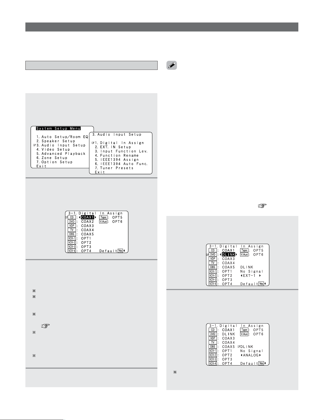
104
Advanced Setup – Part 1
Setting the Digital In Assignment
• This assigns the digital input terminals for the different input
sources.
1
Press the CURSOR
DD
or
HH
button to select
“Audio Input Setup” at the “System Setup
Menu”, then press the
ENTER button.
• The “Audio Input Setup” menu appears.
2
Press the CURSOR
DD
or
HH
button to select
“Digital In Assign”, then press the
ENTER
button.
• The “Digital In Assign” screen appears.
3
Press the CURSOR
DD
or
HH
button to select the
input source, then press the
CURSOR
FF
or
GG
button to select the digital input terminal.
Select from among COAX 1 to 6, OPT 1 to 5.
If the same digital input terminal is selected, the
setting for the input source that was previously
assigned switches to “OFF”.
The HDMI input terminal is displayed when it is
assigned to the input source at “HDMI/DVI In Assign”
( page 111, 112).
If an input source is assigned to a device connected
with an IEEE1394 cable at “IEEE1394 Assign”, the
digital input terminal’s assignment setting switches to
“OFF”.
When “Default Yes” is selected, then press the
CURSOR
FF
button to reset to the default values.
Audio Input Setup
•Make the audio-related settings.
4
Press the ENTER button to enter the setting.
• The “Audio Input Setup” menu reappears.
• The OPTICAL 3, 4 and 5 terminals on the AVR-5805CI’s rear
panel are equipped with an optical digital output terminal for
recording digital audio signals to a CD recorder, MD recorder,
or other digital audio recording deck. Use this for digital
recording between a digital audio source (stereo – 2 channel)
and a digital audio recorder.
• “PHONO” and “TUNER” cannot be selected on the “Digital
In Assign” screen.
• Do not connect the output of the component connected to
the OPTICAL 3 (to 5) OUT terminal on the AVR-5805CI’s rear
panel to any terminal other than the OPTICAL 3 (to 5) IN
terminal.
1
Press the CURSOR
DD
or
HH
button to select the
input source, then press the
CURSOR
FF
or
GG
button to select “DLINK”.
2
Press the CURSOR
DD
or
HH
button to select
“DLINK” setting, then press the
CURSOR
FF
or
GG
button to select the input signal (ANALOG,
EXT. IN or IEEE1394).
If the signal cannot be played with DENON LINK
connection, the signal automatically switches to the
input from the set terminal.
2
Setting the DENON LINK
• When a DENON DVD player and the DENON LINK have
been connected, be sure to make a setting to “DENON
LINK” with the System Setup Digital In Assignment.
• When the input mode is AUTO and the signals are not be
able to transferred by DENON LINK, the unit automatically
changes over the input to the selected signals (ANALOG,
EXT. IN or IEEE1394).
• Refer to “DENON LINK connections” ( page 35).
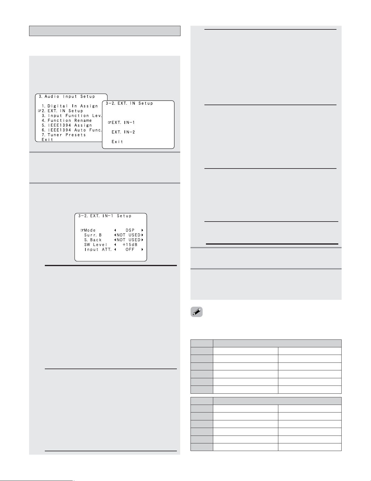
EXT. IN-2 (6 CH)
EXT. IN-1 (10 CH)
105
Advanced Setup – Part 1
Setting the EXT. IN Setup
• Set the EXT. IN terminals playback method.
1
Press the CURSOR
DD
or
HH
button to select
“EXT. IN Setup” at the “Audio Input Setup”
menu, then press the
ENTER button.
• The “EXT. IN Setup” screen appears.
3
Press the CURSOR
DD
or
HH
button to select the
item to be set, then press the
CURSOR
FF
or
GG
button to select the parameter.
S. Back:
Set when “Mode” is set to “DSP”. Select according
to the specifications of the player being used. Also
refer to the player’s operating instructions.
• NOT USED:
Select when neither SBL or SBR is connected.
• SB (SBL):
Select when only one surround back channel (SBL)
is connected.
• SBL/SBR:
Select when two surround back channels (SBL and
SBR) are connected.
Mode:
• DSP:
The analog input signal is converted into a digital
signal and undergoes DSP processing.
System Setup settings (Speaker Configuration,
Delay Time, etc.) are reflected in the same way as
for other input signals.
The surround playback mode button functions.
• ANALOG:
The analog input signal is played without DSP
processing.
SW and center channel: Down-mixing is conducted
by the analog circuit. Surround and surround back
channels: Not output if “No” is selected at the
Speaker Configuration. Delay Time: Not reflected.
4
Press the ENTER button to enter the setting.
• The “EXT. IN Setup” menu reappears.
Surr. B:
Select according to the specifications of the player
being used. Also refer to the player’s operating
instructions.
• NOT USED:
Select when Surround B is not terminals.
The Surround A input signal is output to the
Surround B output terminals.
• USED:
Select when Surround B is connected. The
playback in the MULTI CH DIRECT and MULTI CH
IN is only possible when “Mode” is set to “DSP”.
INPUT ATT.:
Set when “Mode” is set to “DSP”.
If “OVER LOAD” appears on the display, select “–6 dB”.
SW Level :
Select according to the specifications of the player
being used. Also refer to the player’s operating
instructions.
Set the level of playback of the analog input signal
connected to the EXT. IN Subwoofer.
+15dB (default) recommended. (0, +5, +10 and
+15 can be selected.)
Surr. Sp :
Set when “Mode” is set to “ANALOG”. Select
according to the specifications of the player being
used. Also refer to the player’s operating instructions.
• Surr. A
Select when using surround speakers A.
• Surr. B
Select when using surround speakers B.
• Surr. A+B
Select when using both surround speakers A and B.
2
Press the CURSOR
DD
or
HH
button to select the
input terminal, then press the
ENTER button.
•Switch to the setting screen.
5
Press the CURSOR
DD
or
HH
button to select the
“Exit”, then press the
ENTER button.
• The “Audio Input Setup” menu reappears.
Mode
S. Back
Surr. B
Surr. Sp
SW Level
Input ATT.
DSP
ANALOG
NOT USED, SBL/SBR, SB (SBL)
–
NOT USED / USED
NOT USED / USED
–
Surr. A / Surr. B / Surr. A+B
0, +5, +10, +15 dB
0, +5, +10, +15 dB
OFF, –6 dB
–
• The items to be set differ as described below according to
the selected input terminal and the “Mode” selection.
Mode
S. Back
Surr. B
Surr. Sp
SW Level
Input ATT.
DSP
ANALOG
–
–
–
–
–
Surr. A / Surr. B / Surr. A+B
0, +5, +10, +15 dB
0, +5, +10, +15 dB
OFF, –6 dB
–
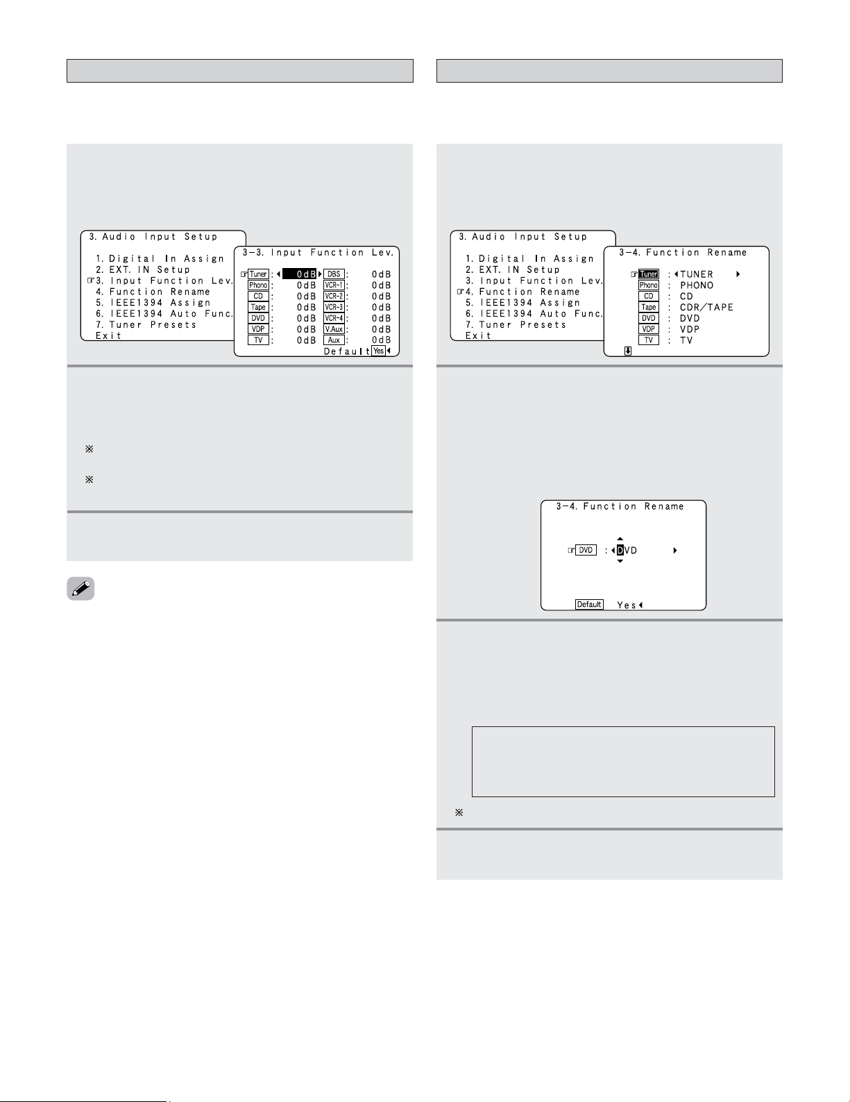
106
Advanced Setup – Part 1
Setting the Input Function Level
• The playback level is corrected individually for the different
input sources.
1
Press the CURSOR
DD
or
HH
button to select
“Input Function Lev.” at the “Audio Input
Setup” menu, then press the
ENTER button.
• The “Input Function Lev.” screen appears.
2
Press the CURSOR
DD
or
HH
button to select the
input source, then press the
CURSOR
FF
or
GG
button to adjust the level.
The level can be adjusted between –12 dB and +12 dB
in units of 1 dB.
When “Default Yes” is selected, then press the
CURSOR
FF
button to reset to the default values.
3
Press the ENTER button to enter the setting.
• The “Audio Input Setup” menu reappears.
• After completing this setting, check that the playback levels
for the different sources are the same.
1
Press the CURSOR
DD
or
HH
button to select
“Function Rename” at the “Audio Input
Setup” menu, then press the
ENTER button.
• The “Function Rename” screen appears.
2
Press the CURSOR
DD
or
HH
button to select the
input function whose name you want to
change, then press the
CURSOR
FF
or
GG
button.
• The screen switches to the character input screen.
Example: When “DVD” is selected and the CURSOR
FF
or
GG
button is pressed
Setting the Function Rename
• The names of the different input function can be changed as
desired and displayed on the display.
3
Press the CURSOR
FF
or
GG
button to move the
cursor (
22
) to the character, number, symbol or
punctuation mark you wish to input, and press
the
CURSOR
DD
or
HH
button to select that
character.
AB C D E F G H I J K L M N O P Q R S T U V W
X Y Z a b c d e f g h i j k l m n o p q r s t u v w x y
z 0 1 2 3 4 5 6 7 8 9
! ” # % & ’ ( )
*
+ , – . / : ; < = > ? @ [ \ ] (space)
Up to 8 characters can be input.
4
Repeat step 3 to input the input function name.
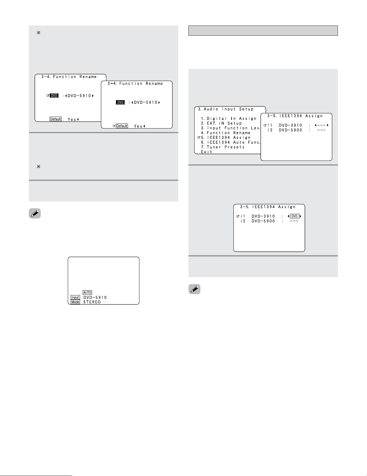
Advanced Setup – Part 1
107
To reset the input function name to the default value,
press the CURSOR
FF
or
GG
button to highlight the input
function display, then press the CURSOR
HH
button
.
When “Default Yes” is selected, then press the
CURSOR
FF
button to reset to the default input function
name.
5
Once all the characters have been input, press
the
ENTER button.
• The “Function Rename” screen reappears.
Use the same procedure to change other input
function names as well.
6
Press the ENTER button to enter the setting.
• The “Audio Input Setup” menu reappears.
• When the input function is selected, the display is as shown
below.
Example: When the name has been changed to “DVD-
5910”
• If you do not wish to assign the device connected by
IEEE1394 cable to an input source, the IEEE1394 input can
be selected by turning the FUNCTION knob. In this case, the
connection information is cleared when the power of the
connected device or the AVR-5805CI is turned off, so the
selection procedure must be performed again.
• By default, if no device has been connected using an
IEEE1394 cable in the past, “No Connection” is displayed.
• “Connection Change” is displayed if there is a change in the
IEEE1394 connection status while this screen is displayed.
• If the model name cannot be acquired from the connected
IEEE1394 device, “UNKNOWN” is displayed.
• If an IEEE1394 device other than one for IEEE1394 audio
playback is connected, “Not Play” is displayed and the input
source cannot be assigned.
Setting the IEEE1394 Assignment
• Assign the device connected by IEEE1394 cable to an input
source. The power of the device to be assigned must be
turned on ahead of time.
1
Press the CURSOR
DD
or
HH
button to select
“IEEE1394 Assign” at the “Audio Input
Setup” menu, then press the
ENTER button.
• The “IEEE1394 Assign” screen appears.
2
Press the CURSOR
DD
or
HH
button to select the
device to be assigned to the input source, then
press the
CURSOR
FF
or
GG
button to select the
input source.
3
Press the ENTER button to enter the setting.
• The “Audio Input Setup” menu reappears.
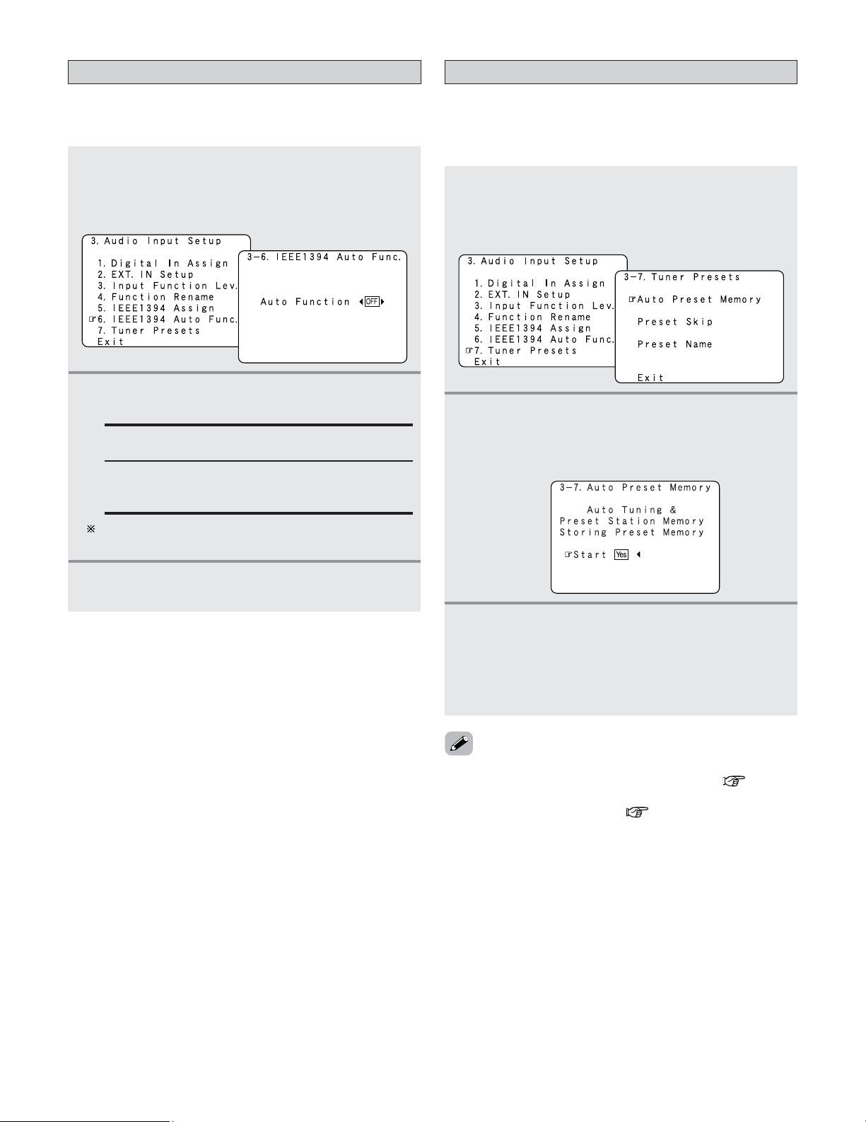
108
Advanced Setup – Part 1
Setting the IEEE1394 Auto Function
• Set whether or not to automatically play the IEEE1394
device when it is selected with the FUNCTION knob.
1
Press the CURSOR
DD
or
HH
button to select
“IEEE1394 Auto Func.” at the “Audio Input
Setup” menu, then press the
ENTER button.
• The “IEEE1394 Auto Func.” screen appears.
2
Press the CURSOR
FF
or
GG
button to select
“ON” or “OFF”.
3
Press the ENTER button to enter the setting.
• The “Audio Input Setup” menu reappears.
OFF:
Select this if you do not want to automatically play
the device.
ON:
Select this to automatically play the device.
In some cases settings may be required on your player.
Also refer to the player’s operating instructions.
Tuner Presets
2 Auto Preset Memory
• FM stations are received automatically and stored in the
memory.
1
Press the CURSOR
DD
or
HH
button to select
“Tuner Presets” at the “Audio Input Setup”
menu, then press the
ENTER button.
• The “Tuner Presets” screen appears.
2
Press the CURSOR
DD
or
HH
button to select
“Auto Preset Memory”, then press the
ENTER
button.
• Switch to the “Auto Preset Memory” screen.
3
Press the CURSOR
FF
button to select “Yes”.
• “Search” flashes on the screen and searching
begins.
• “Completed” appears once searching is completed.
• The display automatically switches to the “Tuner
Presets” screen.
• If an FM station cannot be preset automatically due to poor
reception, use the “Manual tuning” operation ( page 66)
to tune in the station, then preset it using the manual
“Preset memory” operation ( page 66).
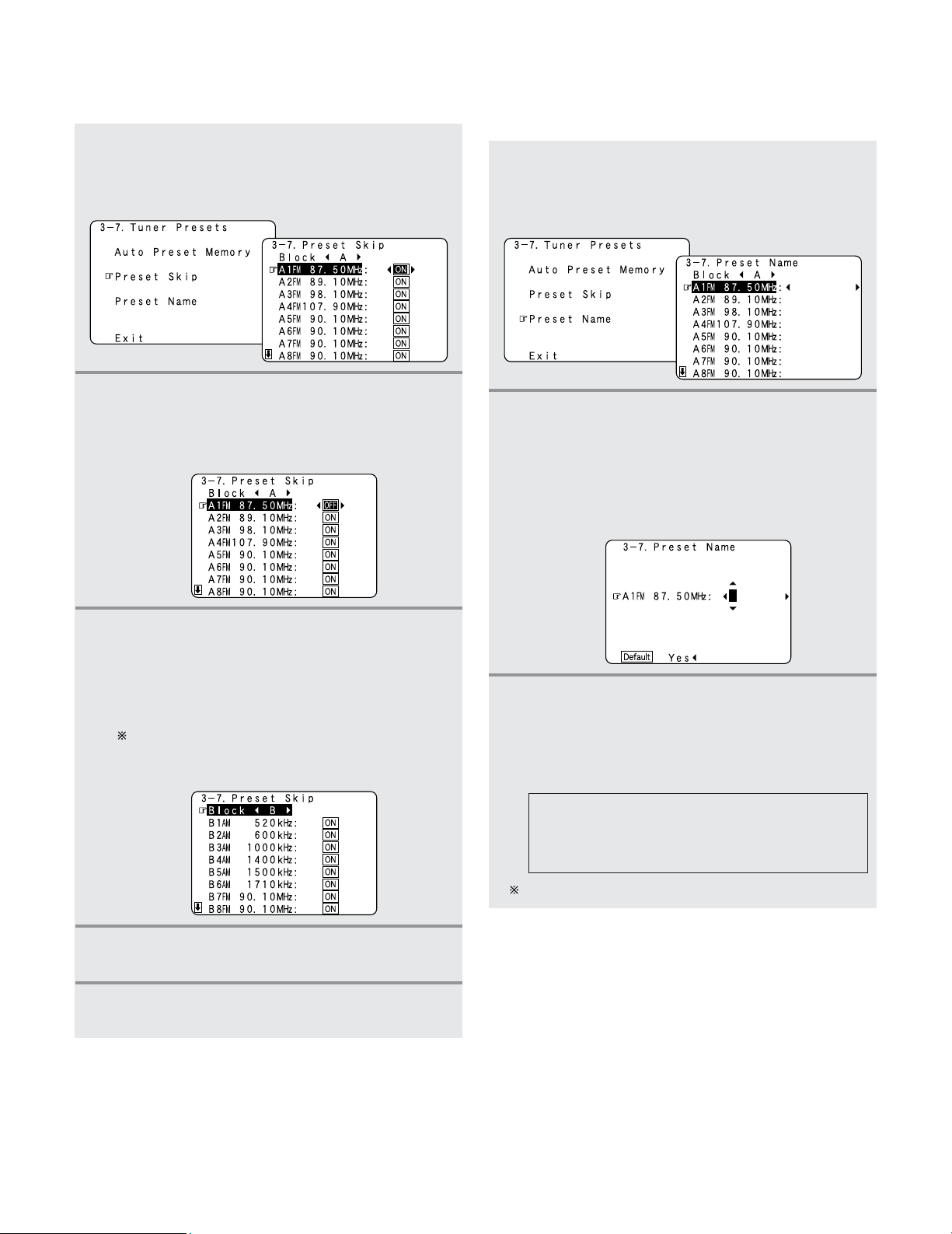
109
Advanced Setup – Part 1
2 Preset Skip
•Preset channels that are not used often can be skipped.
1
Press the CURSOR
DD
or
HH
button to select
“Preset Skip” at the “Tuner Presets” screen,
then press the
ENTER button.
• Switch to the “Preset Skip ”screen.
2
Press the CURSOR
DD
or
HH
button to select the
preset channel you want to skip, then press the
CURSOR
FF
or
GG
button to select “ON” or
“OFF”.
3
Press the CURSOR
HH
button at the very bottom
of the screen to select the next preset memory
block.
• The screen for the next preset memory block
appears.
It is also possible to select the desired preset
memory block by selecting “Block” then pressing
the CURSOR
FF
or
GG
button.
4
Repeat steps 2 and 3.
5
Press the ENTER button.
• The “Tuner Presets” screen reappears.
2 Preset Name
• The preset channels can be given the names you want.
(Except the XM channels.)
1
Press the CURSOR
DD
or
HH
button to select
“Preset Name” at the “Tuner Presets” screen,
then press the
ENTER button.
• Switch to the “Preset Name” screen.
AB C D E F G H I J K L M N O P Q R S T U V W
X Y Z a b c d e f g h i j k l m n o p q r s t u v w x y
z 0 1 2 3 4 5 6 7 8 9
! ” # % & ’ ( )
*
+ , – . / : ; < = > ? @ [ \ ] (space)
3
Press the CURSOR
FF
or
GG
button to move the
cursor (
22
) to the character, number, symbol or
punctuation mark you wish to input, and press
the
CURSOR
DD
or
HH
button to select that
character.
2
Press the CURSOR
DD
or
HH
button to select the
preset channel whose name you want to
change, then press the
CURSOR
FF
or
GG
button.
• The screen switches to the character input screen.
Example: When “A1” is selected and the CURSOR
FF
or
GG
button is pressed
Up to 8 characters can be input.
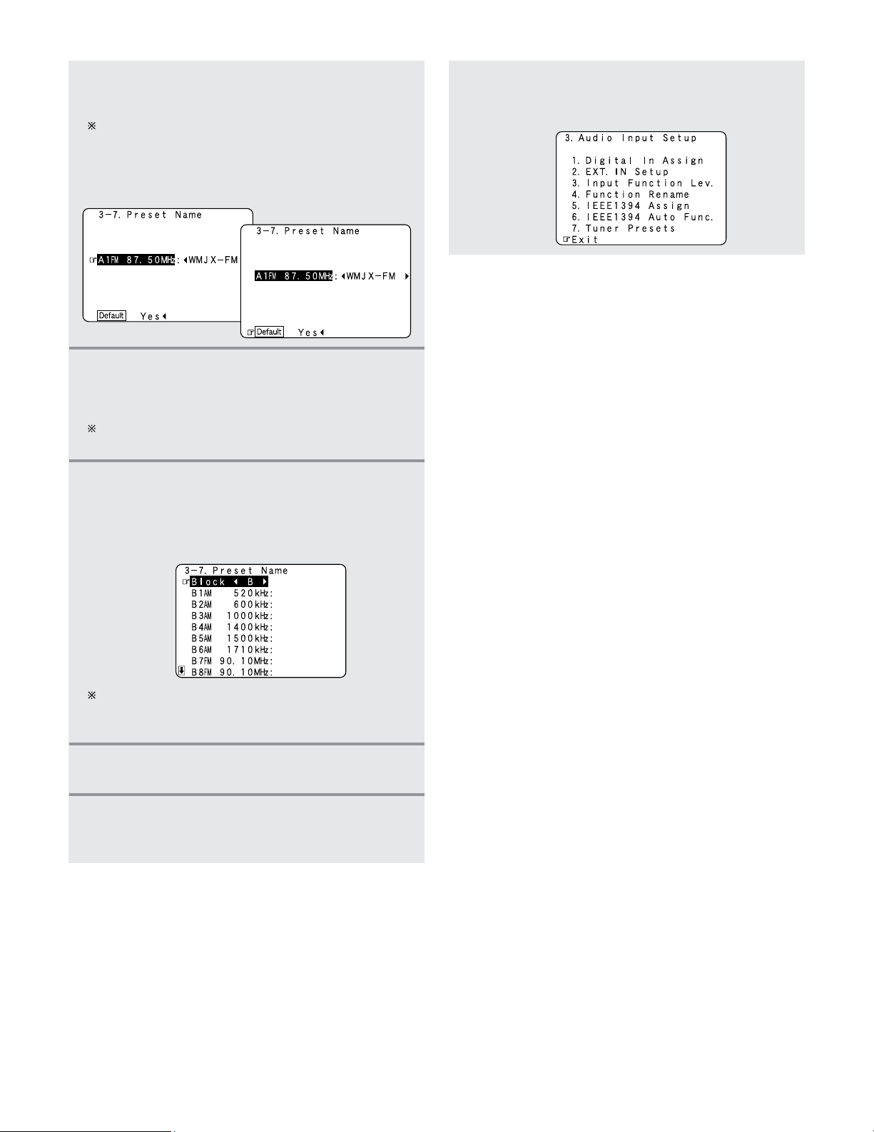
110
Advanced Setup – Part 1
4
Repeat step 3 to input the preset channel
name.
To reset the preset channel name to the default value,
press the CURSOR
FF
or
GG
button to highlight the preset
channel display, then press the CURSOR
HH
button
.
When “Default Yes” is selected, then press the
CURSOR
FF
button to reset to the default name.
5
Once all the characters have been input, press
the
ENTER button.
• The “Preset Name” screen reappears.
Use the same procedure to change other input station
names as well.
6
Press the CURSOR
HH
button at the very bottom
of the screen to select the next preset memory
block.
• The screen for the next preset memory block
appears.
It is also possible to select the desired preset memory
block by selecting “Block” then pressing the CURSOR
FF
or
GG
button.
Press the CURSOR
DD
or
HH
button to select
“Exit”, then press the
ENTER button.
• The “Audio Input Setup” menu reappears.
8
Press the ENTER button to enter the setting.
• The “Tuner Presets” screen reappears.
7
Press the CURSOR
DD
or
HH
button to select
“Exit”, then press the
ENTER button.
• The “System Setup Menu” reappears.
9
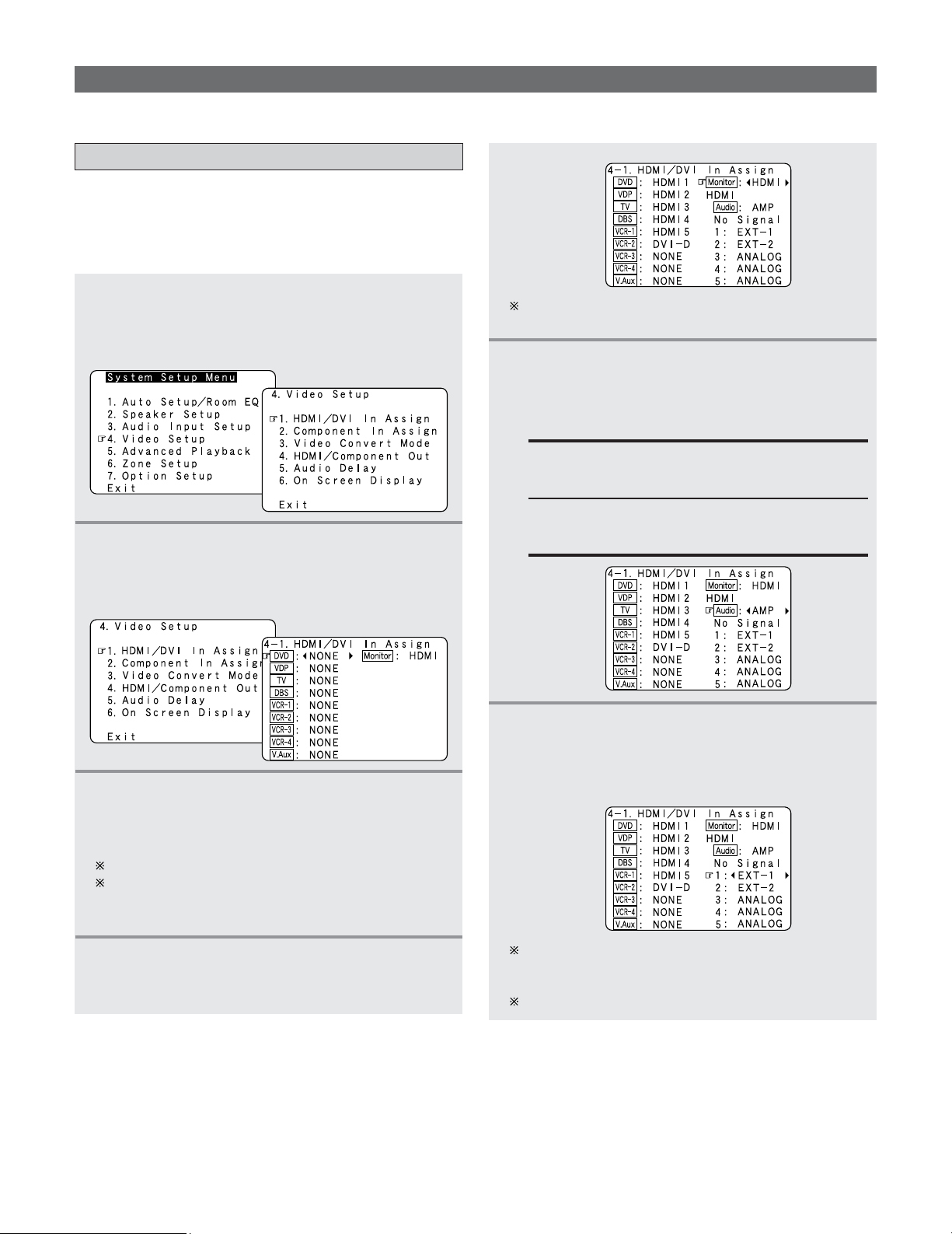
111
Advanced Setup – Part 1
Video Setup
•Make the video-related settings.
Setting the HDMI/DVI In Assignment
• The HDMI or DVI-D input terminals are assigned for the
different input sources.
Select HDMI or DVI-D for the monitor output terminal.
Select the HDMI audio signal playback method.
2
Press the CURSOR
DD
or
HH
button to select
“HDMI/DVI In Assign”, then press the
ENTER
button.
• The “HDMI/DVI In Assign” screen appears.
3
Press the CURSOR
DD
or
HH
button to select the
input source, then press the
CURSOR
FF
or
GG
button to select the input terminal.
Select from among HDMI 1 to 5 and DVI-D.
If the same HDMI or DVI-D input terminal is selected,
the setting for the input source that was previously
assigned switches to “NONE”.
5
Press the CURSOR
DD
or
HH
button to select
“Audio”, then press the
CURSOR
FF
or
GG
button
to select the method for playing the audio
signals included in the HDMI input signal.
AMP:
Play the audio signals on speakers connected to
the AVR-5805CI.
TV:
Play the audio signals on a TV connected to the
AVR-5805CI.
6
Press the CURSOR
DD
or
HH
button to select the
input (1 to 5), then press the
CURSOR
FF
or
GG
button to select the analog input terminal
(EXT. IN or ANALOG).
If there is no HDMI audio signal or the audio signal of
HDMI can not be reproduced, the signal automatically
switches to the input from the set terminal.
1~5 correspond to each HDMI 1~5 input terminal.
1
Press the CURSOR
DD
or
HH
button to select
“Video Setup” at the “System Setup Menu”,
then press the
ENTER button.
• The “Video Setup” menu appears.
This setting can be switched directly using the
MONITOR SELECT button on the main unit.
4
Press the CURSOR
DD
or
HH
button to select
“Monitor”, then press the
CURSOR
FF
or
GG
button to select the monitor output terminal.
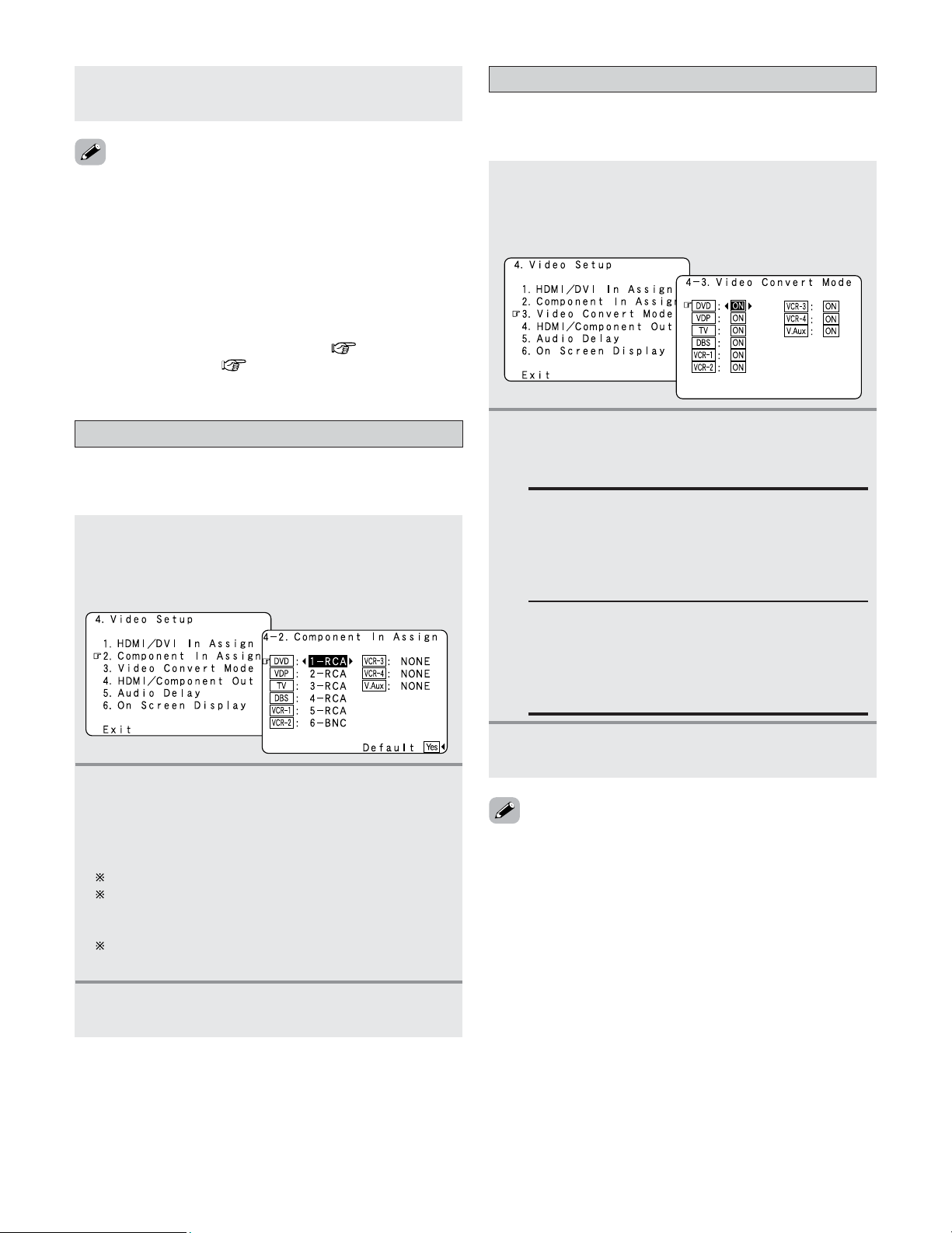
112
Advanced Setup – Part 1
Setting the Component In Assignment
• This assigns the component (color difference) video input
terminals for the different input sources.
1
Press the CURSOR
DD
or
HH
button to select
“Component In Assign” at the “Video Setup”
menu, then press the
ENTER button.
• The “Component In Assign” screen appears.
2
Press the CURSOR
DD
or
HH
button to select the
input source, then press the
CURSOR
FF
or
GG
button to select the component video input
terminal.
Select from among 1-RCA to 5-RCA and 6-BNC.
If the same component video input terminal is
selected, the setting for the input source that was
previously assigned switches to “NONE”.
When “Default Yes” is selected, then press the
CURSOR
FF
button to reset to the default values.
3
Press the ENTER button to enter the setting.
• The “Video Setup” menu reappears.
2
Press the CURSOR
DD
or
HH
button to select the
input source, then press the
CURSOR
FF
or
GG
button to select “ON” or “OFF”.
ON:
When there are multiple input signals, the input
signals are detected and the input signal to be
output from the video monitor output terminal is
selected automatically in the following order:
component video, S-Video, composite video.
Setting the Video Convert Mode
• This sets whether or not to use the video conversion
function.
1
Press the CURSOR
DD
or
HH
button to select
“Video Convert Mode” at the “Video Setup”
menu, then press the
ENTER button.
• The “Video Convert Mode” screen appears.
• Audio signals input from the analog and digital terminals are
not output to the TV.
•With HDMI, the video and audio signals are transferred
simultaneously. When HDMI is assigned to an input source,
the digital audio input assignment switches to HDMI along
with the video input.
When this setting is made for input sources to which a digital
audio input (DENON LINK, IEEE1394 etc.) is previously
assigned, the digital audio assignment is set to HDMI.
In this case, reassign the digital input using the procedure
described at “Digital In Assign” ( page 104) and
“IEEE1394 Assign” ( page 107).
OFF:
The convert function does not operate.
In such cases, the input device’s cable type must
be the same as the type of cable connected to the
AVR-5805CI’s monitor output terminal (video, S-
Video or component video).
3
Press the ENTER button to enter the setting.
• The “Video Setup” menu reappears.
• Down-converting from the component video signal to the S-
Video and composite video signal is possible only when the
resolution of a component video signal is 480i / 576i.
• When a non-standard video signal from a game machine or
some other source is input, the video conversion function
might not operate. If this happens, please set the conversion
mode to “OFF”.
•When the video conversion function has been used,
information such as that of text broadcasts which has been
added to the video signal might not be output. If this
happens, please set the conversion mode to “OFF”.
7
Press the ENTER button to enter the setting.
• The “Video Setup” menu reappears.
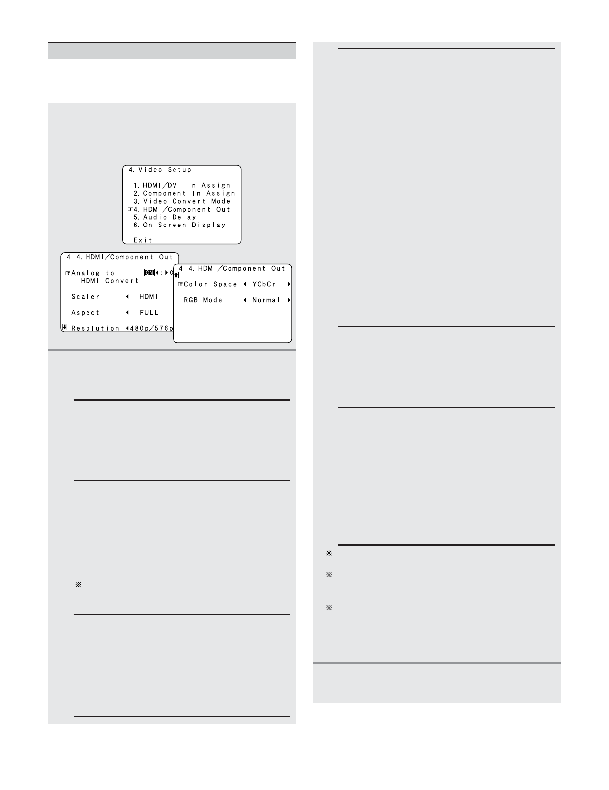
113
Advanced Setup – Part 1
2
Press the CURSOR
DD
or
HH
button to select the
setting, then press the
CURSOR
FF
or
GG
button
to select the parameter.
Analog to HDMI Convert:
• ON:
Setting for converting analog video signals into
HDMI signals.
• OFF:
Setting for not converting analog video signals into
HDMI signals.
Color Space:
• Y Cb Cr:
The Y Cb Cr format video signals is output via the
HDMI output terminal.
• RGB:
The RGB format video signals is output via the
HDMI output terminal.
Setting the HDMI/Component Out Setup
• Set the format of the signal up-converted to the HDMI
monitor output or component video output terminal.
1
Press the CURSOR
DD
or
HH
button to select
“HDMI/Component Out” at the “Video
Setup” menu, then press the
ENTER button.
• The “HDMI/Component Out” screen appears.
Aspect:
• FULL:
The video is output while maintaining the aspect
ratio of the input video.
This mode is suited for playing back 16:9 video.
• NORMAL:
A black band is added to the left and right of the
input video and the video is output.
This mode is suited for playing back 4:3 video.
RGB Mode Setup:
• Normal:
Signals are output via the HDMI output terminal
with a digital RGB video range (data range) of 16
(black) to 235 (white).
• Enhanced:
Signals are output via the HDMI output terminal
with a digital RGB video range (data range) of 0
(black) to 255 (white).
When the HDMI terminal is connected, the black
may seem to stand out, depending on the TV or the
monitor. In this case, set this to “Enhanced”.
When “Y Cb Cr” is selected under “Color Space”,
“RGB Mode Setup” will have no effect.
The “Aspect” setting is valid when the resolution is set
to 1080i, 720p or 1080p. To output with other
resolutions, set the aspect ratio on the TV.
When “Through” is set, the signal is output with the
same resolution as input from the video, S-Video and
component video terminals.
The OSD, however, is output with a resolution of 480i,
so use a monitor compatible with this resolution.
3
Press the ENTER button to enter the setting.
• The “Video Setup” menu reappears.
Resolution:
• 480p/576p:
When the video signal being input is a video, S-
Video or 480i/576i component video signal, the
resolution is converted to 480p/576p and the signal
is output from the HDMI MONITOR OUT terminal.
• 1080i:
When the video signal input is a video, S-Video or
480i/576i/480p/576p component video signal, the
resolution is converted to 1080i and the signal is
output from the HDMI MONITOR OUT terminal.
• 720p:
When the video signal input is a video, S-Video or
480i/576i/480p/576p component video signal, the
resolution is converted to 720p and the signal is
output from the HDMI MONITOR OUT terminal.
• 1080p:
The input video signal is converted to a resolution
of 1080p for output.
This cannot be selected when “Scaler” is set to
“Component”.
• Through:
The video signal input is output as such from the
HDMI MONITOR OUT terminal without being
converted.
Scaler:
• HDMI:
The i/p scaler can be used when outputting the
input analog video signal to the HDMI monitor
output terminal.
• Component:
The i/p scaler can be used when outputting the
input analog video signal to the component video
output terminal.
When “Analog to HDMI Convert” is set to “OFF”,
the “Scaler” setting is automatically set to
“Component” and fixed there.
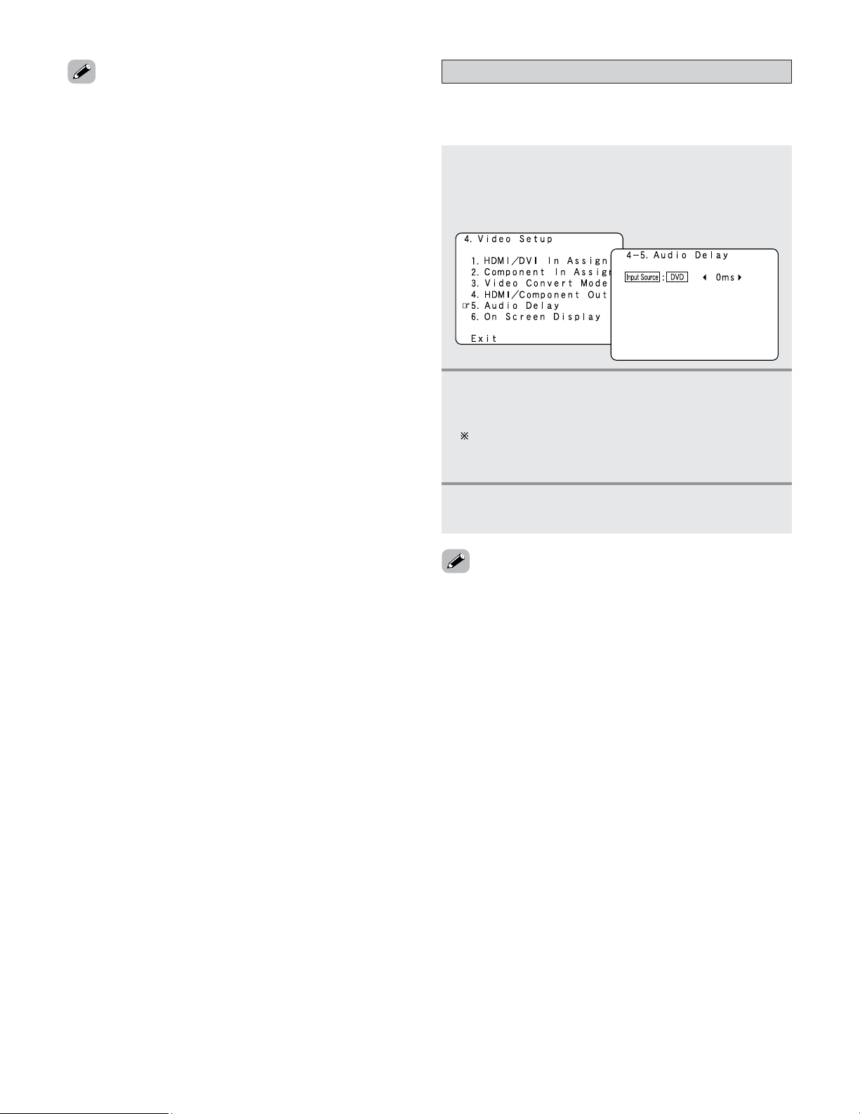
114
Advanced Setup – Part 1
• “Color Space” and “RGB Mode Setup” are only displayed
when “Analog to HDMI Convert” is set to “ON”.
• When connecting to an HDCP compatible monitor equipped
with DVI-D terminal using an HDMI/DVI-D converter cable,
the signals are output in RGB format, regardless of the
“Color Space” setting.
•To view the on screen display using an HDMI monitor, set
“Analog to HDMI Convert” at “HDMI/Component Out” to
“ON” (default).
• Set the resolution of the video output to one that is
compatible with the resolution of your monitor.
• When “Scaler” is set to “Component” and the video input
signal includes copyright protection data, the signal is output
from the component video output terminal with a resolution
of 480p/576p even if “Resolution” is set to “1080i” or
“720p”.
Setting the Audio Delay
• Set the audio delay timing to synchronize the sound and
video.
1
Press the CURSOR
DD
or
HH
button to select
“Audio Delay” at the “Video Setup” menu,
then press the
ENTER button.
• The “Audio Delay” screen appears.
2
Press the CURSOR
FF
or
GG
button to set the
delay time (0 ms ~ 200 ms).
With a movie source, for example, adjust so that the
movement of the actors’ lips is synchronized with the
sound.
3
Press the ENTER button to enter the setting.
• The “Video Setup” menu reappears.
• The audio delay setting does not apply when playing in the
EXT. IN mode or in the analog input DIRECT mode or
STEREO mode (only when the crossover frequency is set to
“FIXED–THX–” or front speaker is set to “Large” (TONE
DEFEAT “ON”, Room EQ “OFF”).
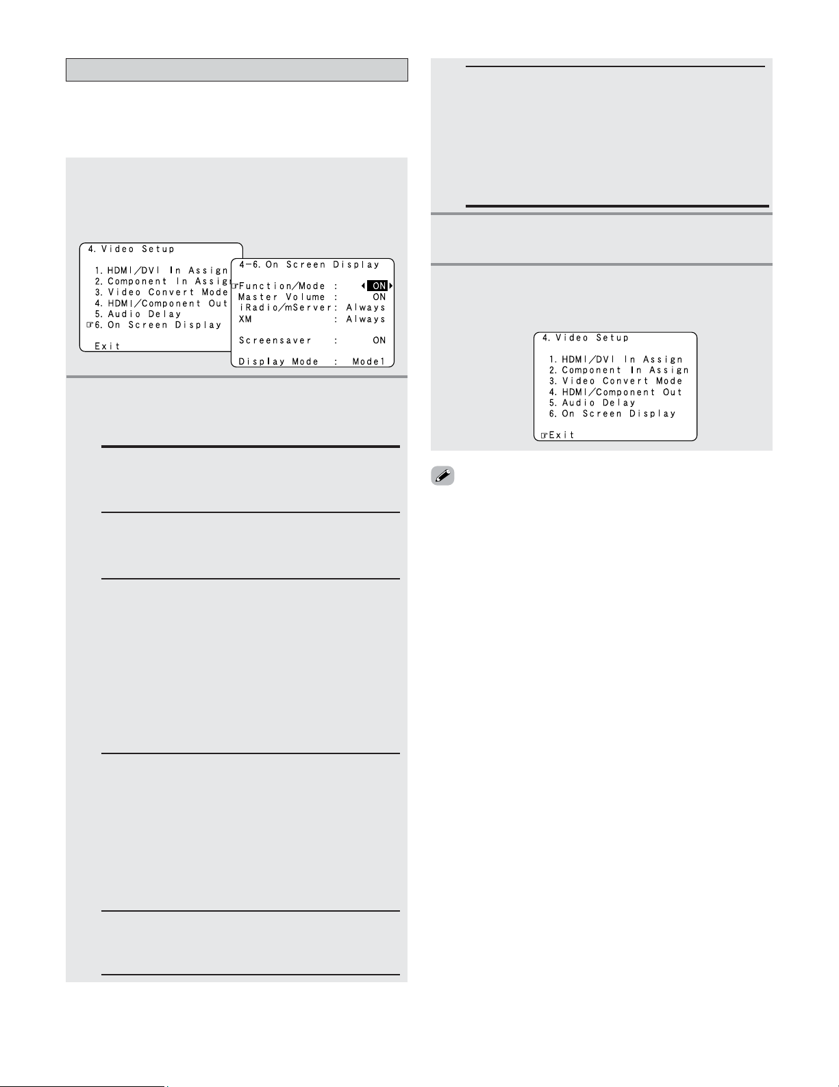
115
Advanced Setup – Part 1
Display Mode:
• Mode 1:
Flickering is not prevented.
• Mode 2:
Prevents flickering of the on screen display when
there is no video signal.
Use this mode if the on screen display does not
appear in the Mode 1, as may happen according to
the TV being used.
Setting the On Screen Display (OSD)
• Use this to turn the on screen display (messages other than
the menu screens) on or off.
• Sets the on screen display’s display mode.
1
Press the CURSOR
DD
or
HH
button to select “On
Screen Display” at the “Video Setup” menu,
then press the
ENTER button.
• The “On Screen Display” screen appears.
2
Press the CURSOR
DD
or
HH
button to select the
item to be set, then press the
CURSOR
FF
or
GG
button to select the parameter.
3
Press the ENTER button to enter the setting.
• The “Video Setup” menu reappears.
Function/Mode Status:
Set whether or not to turn on the on screen display
of the input source name and input mode when an
input source is selected.
Master Volume Status:
Set whether or not to turn on the on screen display
of the main volume level when the main volume is
operated.
4
Press the CURSOR
DD
or
HH
button to select
“Exit”, then press the
ENTER button.
• The “System Setup Menu” reappears.
iRadio/mServer:
Set the time for which the on screen display is
displayed when performing Internet radio and
Music server operations.
Always: The on screen display is always on.
(Default)
5sec: The on screen display turns off 5 seconds
after it turns on.
10sec: The on screen display turns off 10 seconds
after it turns on.
OFF: The on screen display is not displayed.
XM:
Set the time for which the on screen display is
displayed when performing XM operations.
Always: The on screen display is always on.
(Default)
5sec: The on screen display turns off 5 seconds
after it turns on.
10sec: The on screen display turns off 10 seconds
after it turns on.
OFF: The on screen display is not displayed.
Screensaver:
ON: The screensaver is launched if no operation
is performed for approximately 3 minutes.
OFF: The screensaver is not launched.
• The screensaver is launched while in the Internet radio,
Music server or XM mode if the on screen display’s display
time is set to “Always”.
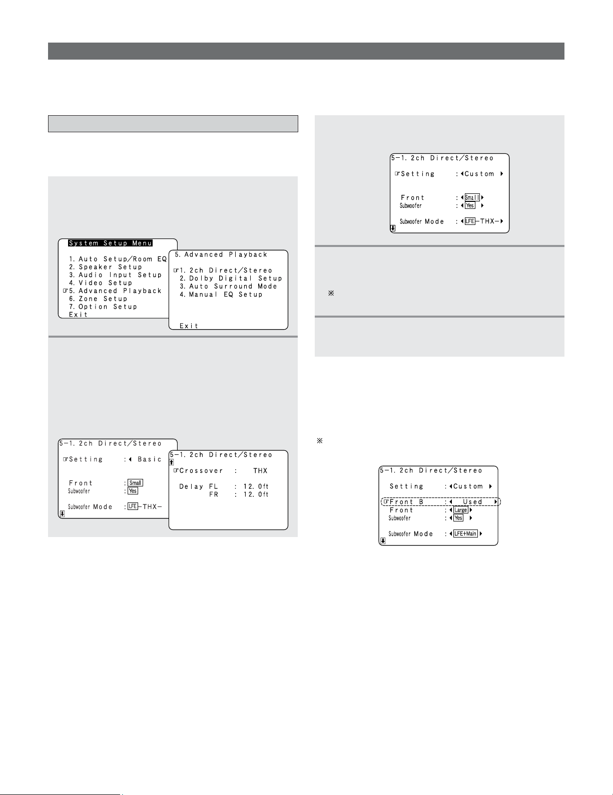
116
Advanced Setup – Part 1
Setting the 2ch Direct/Stereo
• The speaker settings can be changed specifically for playing
in the 2 channel DIRECT or STEREO mode.
1
Press the CURSOR
DD
or
HH
button to select
“Advanced Playback” at the “System Setup
Menu”, then press the
ENTER button.
• The “Advanced Playback” menu appears.
2
Press the CURSOR
DD
or
HH
button to select “2ch
Direct / Stereo”, then press
ENTER button.
• The “2ch Direct/Stereo” screen appears.
Advanced Playback
• Makes more detailed audio playback settings.
2 Setting the front B speakers when the surround
mode is set to the 2 channel Direct or Stereo
• When “Adv+Front B” is selected at “Power Amp Assign”
and “Custom” is selected at this setting, the “Front B”
setting is displayed.
To play signals from the Front B speaker when in the 2
channel Direct or Stereo mode, set “Used”.
5
Press the ENTER button to enter the setting.
• The “Advanced Playback” menu reappears.
3
Press the CURSOR
FF
or
GG
button to select
“Custom”.
4
Press the CURSOR
DD
or
HH
button to select the
item, then press
CURSOR
FF
or
GG
button to set.
For a description of the settings for the different items,
see pages 140 ~ 146.
Example: This screen is displayed in function of the
settings made at “Speaker Configuration”,
“Subwoofer Setup”, “Delay Time” and
“Crossover Frequency”
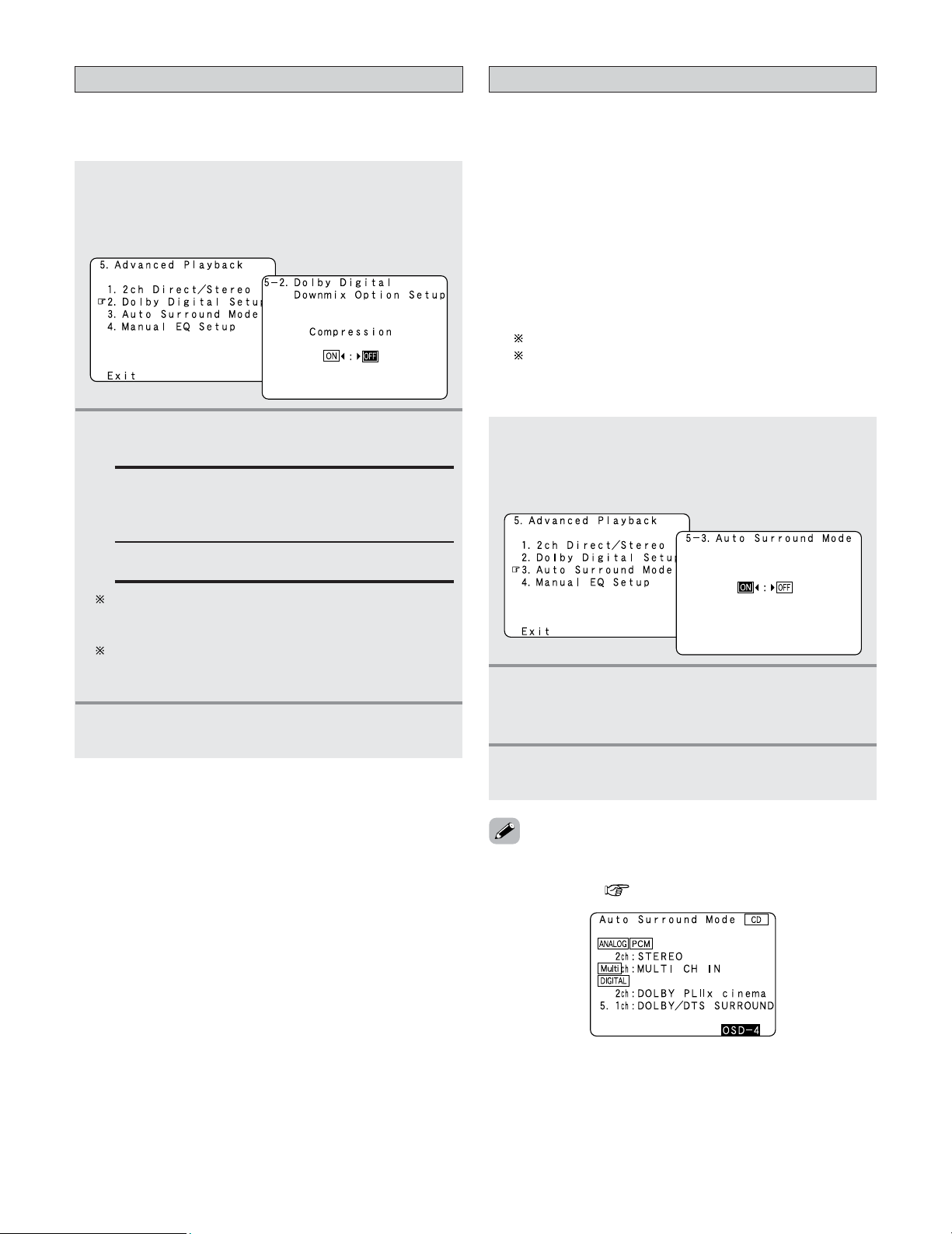
117
Advanced Setup – Part 1
Setting the Dolby Digital Setup
•Turn the audio compression on or off when down-mixing
Dolby Digital signals.
1
Press the CURSOR
DD
or
HH
button to select
“Dolby Digital Setup” at the “Advanced
Playback” menu, then press the
ENTER button.
• The “Dolby Digital Setup” screen appears.
2
Press the CURSOR
FF
or
GG
button to select
“ON” or “OFF”.
OFF:
The dynamic range is not compressed.
ON:
The dynamic range is compressed automatically
according to the combination of speakers being
used.
Set “Compression” to “ON” if it seems that sound is
distorted because the input level exceeds the
allowable input for the front speakers.
When a center speaker or surround speakers are not
connected, the sounds in those channels are directed
to the front speakers.
3
Press the ENTER button to enter the setting.
• The “Advanced Playback” menu reappears.
1
Press the CURSOR
DD
or
HH
button to select
“Auto Surround Mode” at the “Advanced
Playback” menu, then press the
ENTER button.
• The “Auto Surround Mode” screen appears.
2
Press the CURSOR
FF
or
GG
button to select
“ON” if you want to use the auto surround
mode, “OFF” if you do not want to use it.
3
Press the ENTER button to enter the setting.
• The “Advanced Playback” menu reappears.
Setting the Auto Surround Mode
• The various settings applied in the auto surround mode can
be checked via the on screen display. Simply press the ON
SCREEN button ( page 52).
• The surround mode used at last for the four types of input
signals shown below is stored in the memory, and the signal
is automatically played with that surround mode the next
time it is input.
Note that the surround mode setting is also stored
separately for the different input sources.
q Analog and PCM 2 channel signals (STEREO)
w 2 channel signals of Dolby Digital, DTS or other multi-
channel format (DOLBY PL
IIx Cinema)
e Multi-channel signals of Dolby Digital, DTS or other
multi-channel format (DOLBY/DTS SURROUND)
r PCM and DSD multi-channel signals other than Dolby
Digital and DTS (MULTI CH IN)
Default settings are indicated in ( ).
During playback in the PURE DIRECT mode, the
surround mode does not change even if the input signal
is changed.
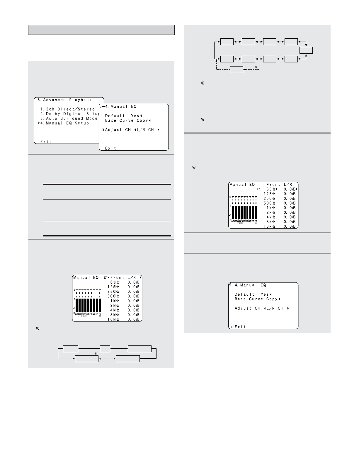
118
Advanced Setup – Part 1
Setting the Manual EQ Setup
1
Press the CURSOR
DD
or
HH
button to select
“Manual EQ Setup” at the “Advanced
Playback” menu, then press the
ENTER button.
• The “Manual EQ” screen appears.
2
Press the CURSOR
FF
or
GG
button to select the
adjustment mode, then press the
ENTER
button.
All CH:
All channels can be adjusted simultaneously.
L/R CH:
The left and right channels of the pair of speakers
can be adjusted simultaneously.
Each CH:
The channels can be adjusted separately.
3
Press the CURSOR
FF
or
GG
button to select the
speaker to be set.
Example: When “L/R CH” is selected.
The display changes as follows.
FL/FR
SBL/SBR
C SLA/SRA
SLB/SRB
w Select the “Each CH”
FL
SBR
1spkr
FR
C
SLA
SLB
SRB
SBL
SRA
SB
q Select the “L/R CH”
When the surround back speaker setting is set to
“1spkr” at “Speaker Configuration”, this is set to
“SB”.
e Select the “All CH”
In this case, speaker selection is not performed.
If a value is already set for the FL channel, the data
stored for the FL channel is displayed.
4
Press the CURSOR
DD
or
HH
button to select the
frequency, then press the
CURSOR
FF
or
GG
button to adjust the gain level.
Each frequency can be adjusted the range from –20.0
dB to +6.0 dB in 0.5 dB step.
5
Press the ENTER button to enter the setting.
• The “Manual EQ” screen reappears.
6
Press the CURSOR
DD
or
HH
button to select
“Exit”, then press the
ENTER button.
• The “Advanced Playback” menu reappears.
• Allows you to adjust the tonal quality of the various speakers
(except the subwoofer) while listening to a music source.
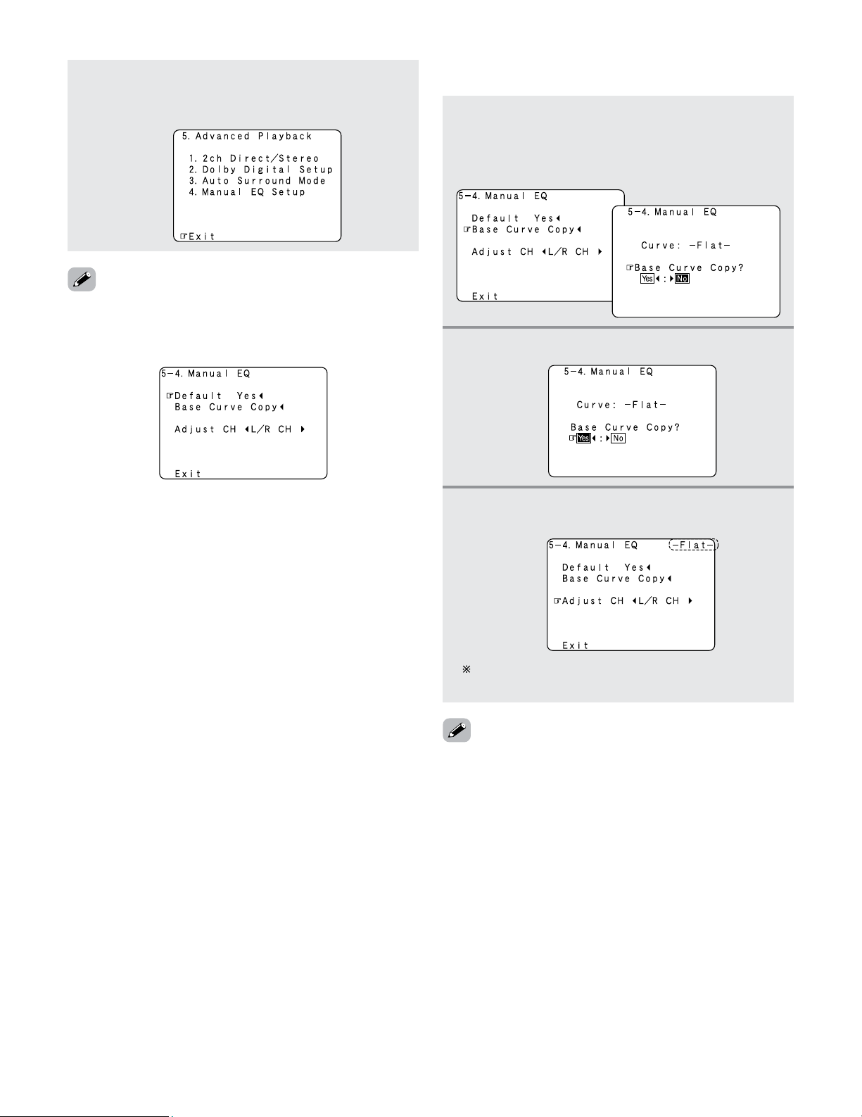
119
Advanced Setup – Part 1
Press the CURSOR
DD
or
HH
button to select
“Exit”, then press the
ENTER button.
• The “System Setup Menu” reappears.
7
• “Base Curve Copy” is displayed after performing the Auto
Setup.
•To restore the settings to their defaults, select “Default Yes
0
”, then press the CURSOR
FF
button.
1
Press the CURSOR
DD
button to select “Base
Curve Copy”, then press the
CURSOR
FF
button.
• Switch to the “Base Curve Copy” screen.
2
Press the CURSOR
FF
button to select “Yes”.
3
Press the ENTER button to enter the setting.
• The “Manual EQ” screen reappears.
The type of the copied correction curve is displayed in
the upper right of this screen.
• If the “Auto Setup” procedure has not been performed, this
item is not displayed.
2
Procedure for copying the “Flat” correction curve
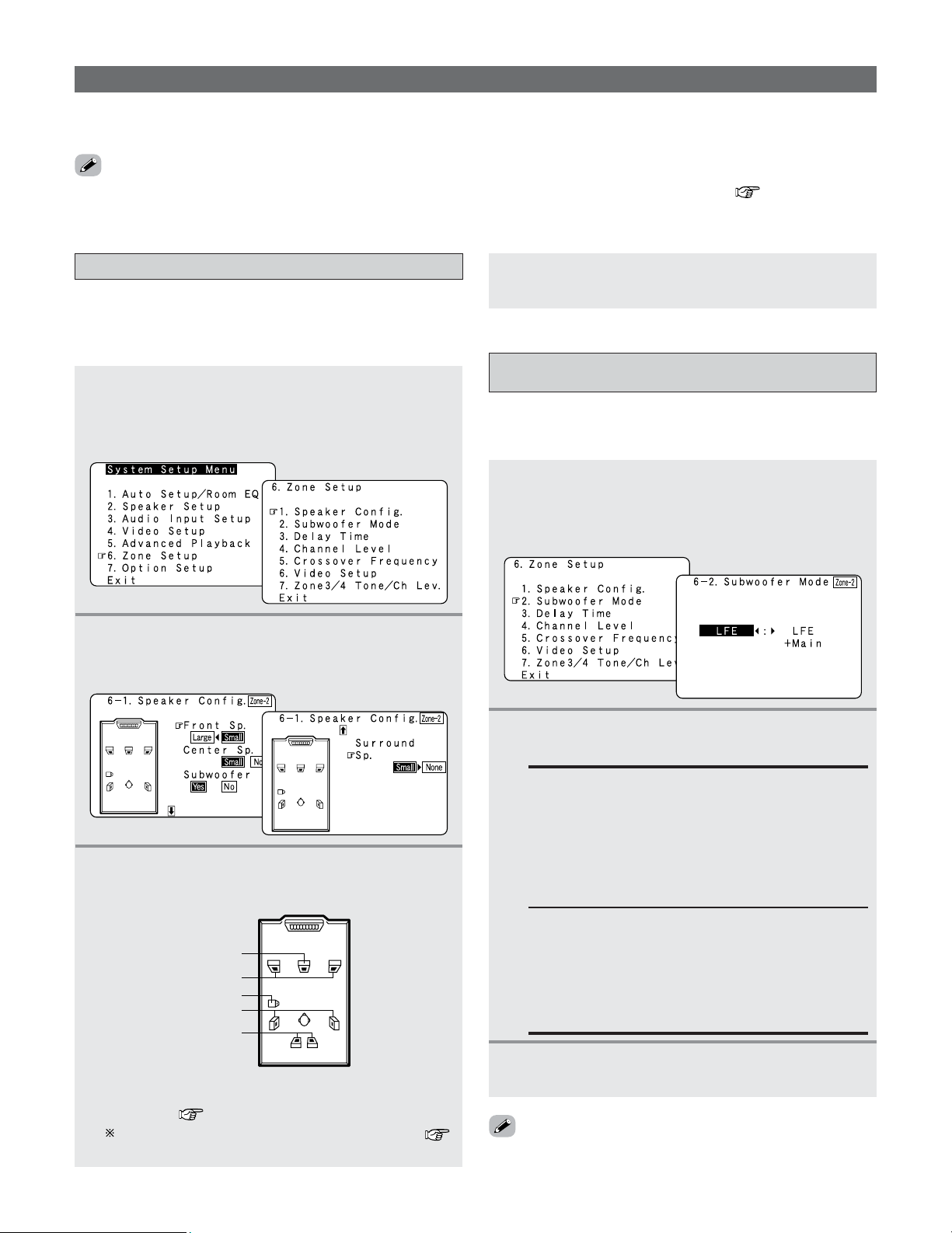
120
Advanced Setup – Part 1
Setting the type of speakers for ZONE2
1
Press the CURSOR
DD
or
HH
button to select
“Zone Setup” at the “System Setup Menu”,
then press the
ENTER button.
• The “Zone Setup” menu appears.
• Set the presence/absence of speaker combinations and the
size in function of the low frequency reproduction
capabilities when playing surround sound in ZONE2.
4
Press the ENTER button to enter the setting.
• The “Zone Setup” menu reappears.
3
Press the CURSOR
DD
or
HH
button to select the
speaker, then press the
CURSOR
FF
or
GG
button
to select the parameter.
2
Press the CURSOR
DD
or
HH
button to select
“Speaker Config.”, then press the
ENTER button.
• The “Speaker Config.” screen appears.
Zone Setup (ZONE2 = 5.1/7.1ch)
•Make the settings related to surround playback and video for ZONE2.
• Adjust the sound played in ZONE3 and ZONE4.
ZONE2 Center Sp.
ZONE2 Front Sp.
ZONE2 Subwoofer
ZONE2 Surround Sp.
(ZONE2 Surround back Sp.)
*
*
This is only displayed when “7.1ch” is selected for
the ZONE2 channel output setting at “Channel
Setup” ( page 126 ~ 128).
For a description of the different parameters (
page 141).
Setting the low frequency distribution for
ZONE2
1
Press the CURSOR
DD
or
HH
button to select
“Subwoofer Mode” at the “Zone Setup” menu,
then press the
ENTER button.
•The “Subwoofer Mode” screen appears.
• This selects the subwoofer used in ZONE2 for playing the
low base sound.
3
Press the ENTER button to enter the setting.
• The “Zone Setup” menu reappears.
2
Press the CURSOR
FF
or
GG
button to select the
setting.
LFE:
For any channel(s) that are set to LARGE, low
frequencies in that channel’s corresponding source
are directed to that loudspeaker only. Low
frequencies that are directed to the subwoofer(s)
are from the program source LFE channel, and
from other channels where the speakers are set to
SMALL.
LFE+Main:
Low frequencies from speaker channels that have
been set to LARGE are reproduced from those
speakers as well as from the subwoofer(s).
Depending upon the characteristics of the LARGE
main speakers, this mode may provide a more even
low frequency response throughout the listening room.
• The subwoofer mode setting is only valid when “Large” is
set for the ZONE2 front speakers and “Yes” is set for the
subwoofer in the “Setting the type of speaker for ZONE2”.
• When “STEREO” or “MONO” is selected for the ZONE2 channel output setting at “Channel Setup” ( page 126 ~ 128),
the menu screen displayed differs. In this case, see the instructions starting at page 125.
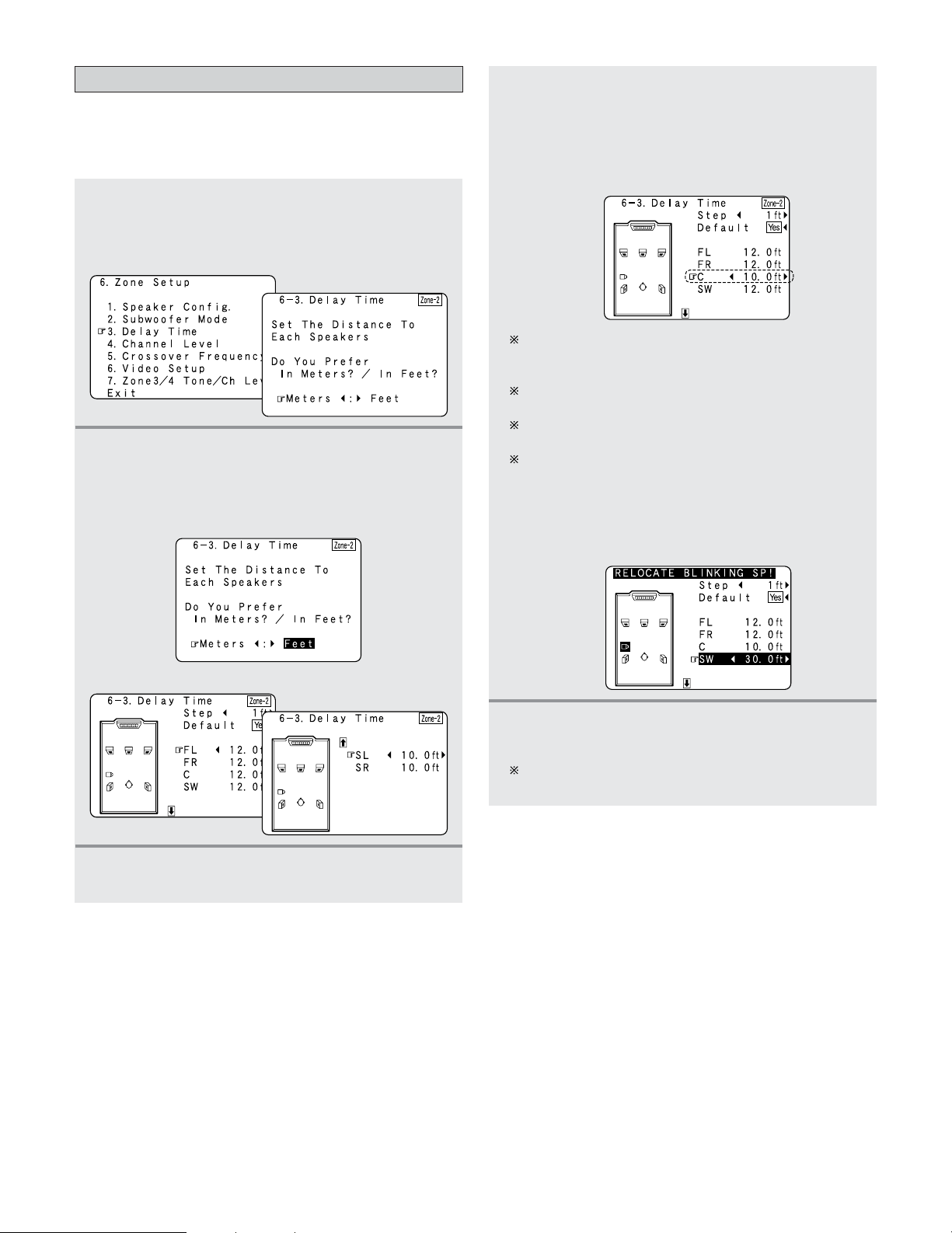
121
Advanced Setup – Part 1
Setting the Delay Time for ZONE2
• This parameter is for optimizing the timing of the sound
produced from the various speakers and subwoofer
according to the listening position in ZONE2.
1
Press the CURSOR
DD
or
HH
button to select
“Delay Time” at the “Zone Setup” menu, then
press the
ENTER button.
• The “Delay Time” screen appears.
2
Press the CURSOR
FF
or
GG
button to select the
desired unit, “Meters” or “Feet”.
• The “Delay Time” screen appears automatically.
Example: When “Feet” is selected
3
Press the CURSOR
DD
or
HH
button to select the
speaker to be set.
4
Press the CURSOR
FF
or
GG
button to set the
distance between the center speaker and
listening position.
Example: When the distance is set to 10.0 feet for the
center speaker
The distance changes in units of 1 foot or 0.1 foot
each time the button is pressed. Select the value
closest to the measured distance.
When “Step” is selected, you can select the unit of “1
ft (0.1 m)” or “0.1 ft (0.01 m)”.
When “Default Yes” is selected, then press the
CURSOR
FF
button to reset to the default values.
The difference of the distances set for the various
speakers must be 20.0 ft (6.0 m) or under. If an
inappropriate distance is set, “RELOCATE
BLINKING SP!” is displayed. In this case, move the
relevant speaker to the proper position as
indicated by the displayed value.
5
Press the ENTER button to enter the setting.
• The “Zone Setup” menu reappears.
The AVR-5805CI automatically sets the optimum
surround delay time for the ZONE2 listening room.
hh
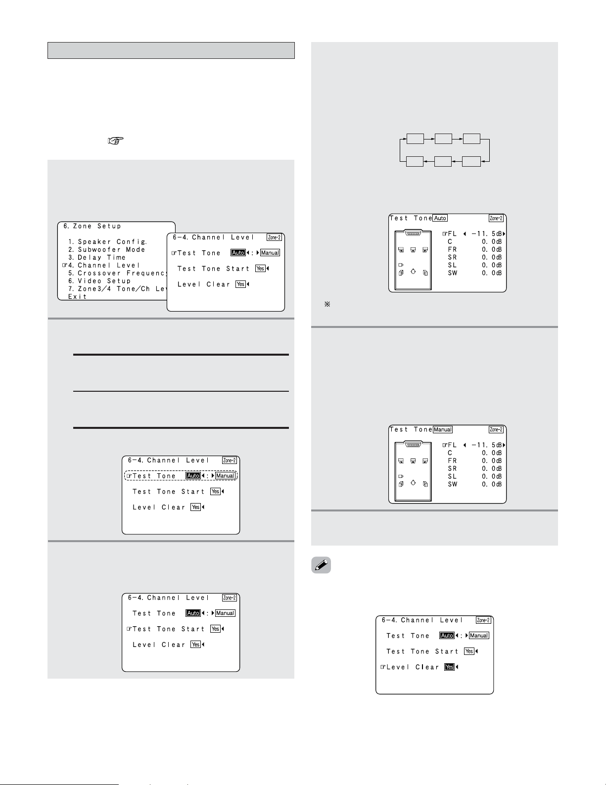
122
Advanced Setup – Part 1
Setting the Channel Level for ZONE2
• Use this setting to adjust so that the playback level between
the different channels of ZONE2 is equal.
•From the ZONE2 listening position, listen to the test tones
produced from the speakers used in ZONE2 to adjust the
level.
• The level can also be adjusted directly from the remote
control unit ( page 95).
1
Press the CURSOR
DD
or
HH
button to select
“Channel Level” at the “Zone Setup” menu,
then press the
ENTER button.
• The “Channel Level” screen appears.
2
Press the CURSOR
FF
or
GG
button to select
“Auto” or “Manual”.
Auto:
Adjust the level while listening to the test tones
produced automatically from each speaker.
Example: When the “Auto” mode is selected
Manual:
Select the speaker from which you want to
produce the test tone to adjust the level.
Press the CURSOR
DD
or
HH
button to select
“Test Tone Start”, then press the
CURSOR
FF
button to select “Yes”.
4
-1
When “Auto” mode is selected:
Press the
CURSOR
FF
or
GG
button to adjust all
the speakers to the same volume.
• The test tones are emitted from each speaker in the
following order, at 4 seconds intervals the first time
and second time around, 2 seconds intervals the
third time around and on:
FL
SW
C
FR
SR
SL
3
The volume can be adjusted between –12.0 dB and
+12.0 dB in units of 0.5 dB.
4
-2
When “Manual” mode is selected:
Press the
CURSOR
DD
or
HH
button to select the
speaker used in ZONE2, then press the
CURSOR
FF
or
GG
button to adjust all the
speakers to the same volume.
Example: “Manual” mode is selected.
5
Press the ENTER button to enter the setting.
• The “Channel Level” screen reappears.
Example: When the volume is set to –11.5 dB while
the test tone is being produced from the
Front L ch speaker
•To cancel the settings, press the CURSOR
FF
button to select
“Level Clear” and “Yes” on the “Channel Level” screen,
then make the settings again.
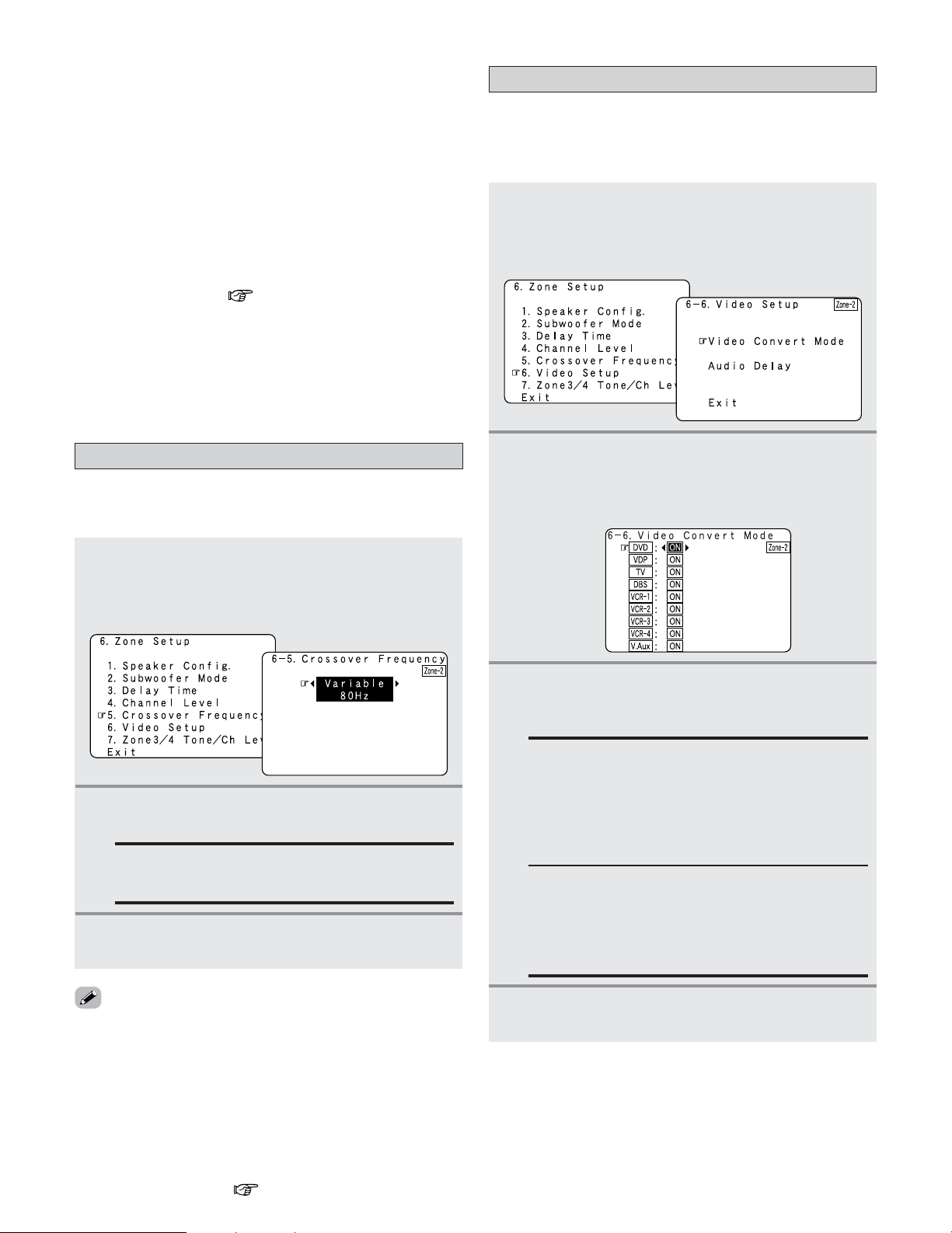
123
Advanced Setup – Part 1
• When adjusting the level of an active subwoofer system,
you may also need to adjust the subwoofer’s own volume
control.
• When you adjust the channel levels while in the SYSTEM
SETUP CHANNEL LEVEL mode, the channel level
adjustments made will affect all surround modes for ZONE2.
• After you have completed the SYSTEM SETUP CHANNEL
LEVEL adjustments, you can then activate the individual
surround modes and adjust channel levels that will be
remembered for each of those modes. Then, whenever you
activate a particular surround sound mode, your preferred
channel level adjustments for just that mode will be recalled.
Check the instructions for adjusting channel levels within
each surround mode ( page 95, 96).
•You can adjust the channel levels for each of the following
surround modes for ZONE2: STEREO, STANDARD
(DOLBY/DTS SURROUND), 5/7 CH STEREO, WIDE
SCREEN, SUPER STADIUM, ROCK ARENA, JAZZ CLUB,
CLASSIC CONCERT, MONO MOVIE, VIDEO GAME,
MATRIX and VIRTUAL.
2
Press the CURSOR
FF
or
GG
button to select the
frequency.
VARIABLE 40, 60, 80, 100, 120, 150, 200, 250 Hz:
Set as desired according to your speakers’ bass
playback ability.
3
Press the ENTER button to enter the setting.
• The “Zone Setup” menu reappears.
Setting the Crossover Frequency for ZONE2
• Set the frequency (in Hz) below which deep bass appearing
in the main channels will be routed to the ZONE2 subwoofer.
1
Press the CURSOR
DD
or
HH
button to select
“Crossover Frequency” at the “Zone Setup”
menu, then press the
ENTER button.
• The “Crossover Frequency” screen appears.
• For the majority of home theater speaker systems, we
recommend that the crossover frequency be set to 80 Hz.
When using very compact speakers, however, it may be
advantageous to select a higher crossover frequency. Check
the specified low frequency limit of each speaker (usually
published in the specifications tables in speaker owner’s
manuals).
• The crossover frequency mode is valid only when subwoofer
is set to “Yes”, and when one or more speakers are set to
SMALL, as described in section “Setting the type of
speakers for ZONE2” ( page 120).
3
Press the CURSOR
DD
or
HH
button to select the
ZONE2 input source, then press the
CURSOR
FF
or
GG
button to select “ON” or “OFF”.
ON:
When there are multiple input signals for the input
sources selected at ZONE2, the input signal is
detected and the input signal output to the
ZONE2’s monitor output terminal is selected
automatically, in the following order of priority:
Component, S-Video, Composite.
Setting the Video Setup for ZONE2
1
Press the CURSOR
DD
or
HH
button to select
“Video Setup” at the “Zone Setup” menu, then
press the
ENTER button.
• The “Video Setup” screen appears.
2 Video Convert Mode (ZONE2)
• This sets whether or not to use the video conversion
function.
2
Press the CURSOR
DD
or
HH
button to select
“Video Convert Mode”, then press the
ENTER
button.
• The “Video Convert Mode” screen appears.
OFF:
The convert function does not operate.
In such cases, the input device’s cable type must
be the same as the type of cable connected to the
AVR-5805CI’s monitor output terminal (video, S-
Video or component video).
4
Press the ENTER button to enter the setting.
• The “Zone Setup” menu reappears.
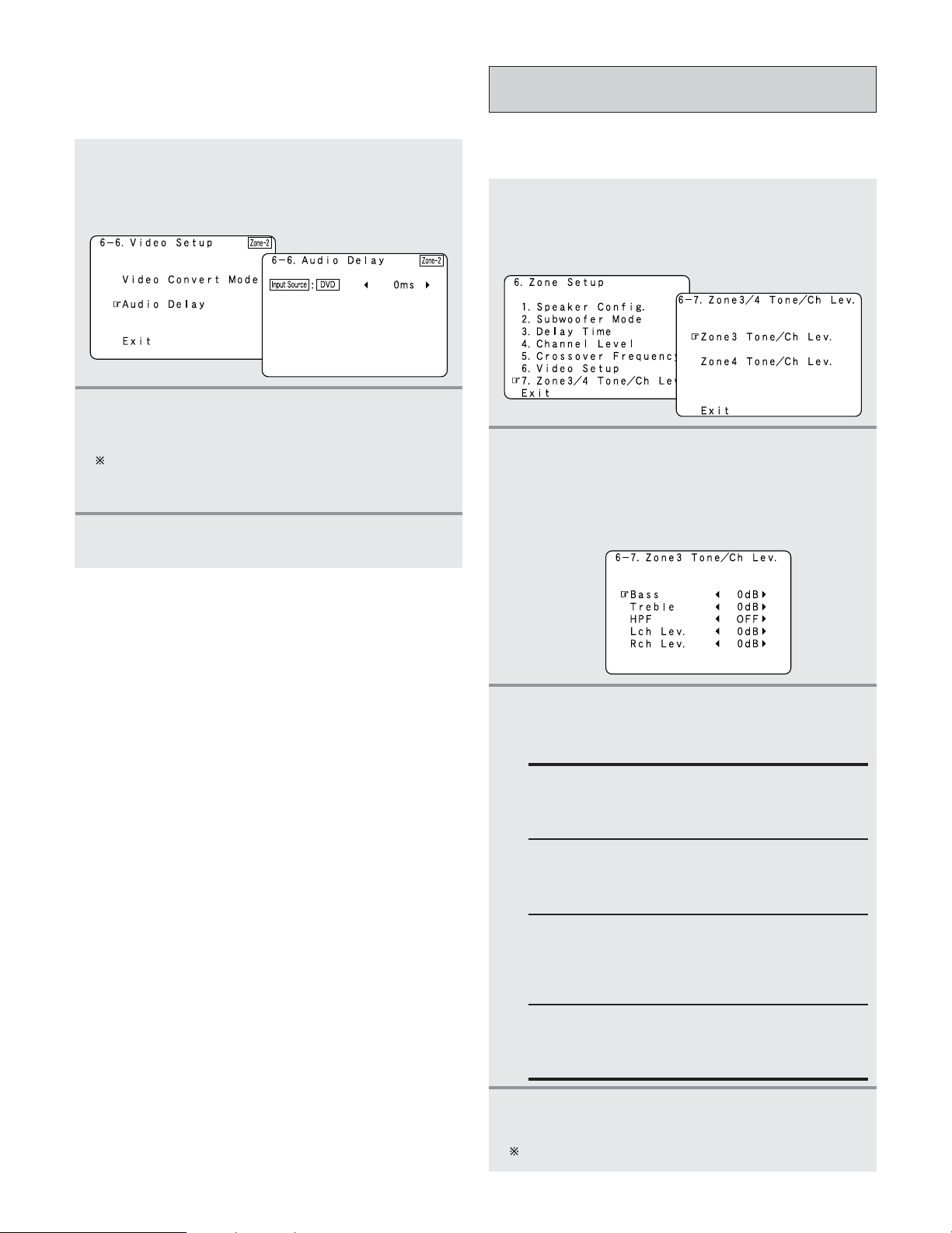
124
Advanced Setup – Part 1
1
Press the CURSOR
DD
or
HH
button to select
“Audio Delay” at the “Video Setup” menu,
then press the
ENTER button.
• The “Audio Delay” screen appears.
2
Press the CURSOR
FF
or
GG
button to set the
delay time (0 ms ~ 200 ms).
With a movie source, for example, adjust so that the
movement of the actors’ lips is synchronized with the
sound.
3
Press the ENTER button to enter the setting.
• The “Zone Setup” menu reappears.
2
Audio Delay (ZONE2)
• Set the delay time the sound is synchronized with the
picture which are output in ZONE2.
Setting the ZONE3 and ZONE4 tone control
and channel level
• Adjust the tone and channel level of the sound output from
ZONE3 and ZONE4.
1
Press the CURSOR
DD
or
HH
button to select
“Zone3/4 Tone/Ch Lev.” at the “Zone Setup”
menu, then press the
ENTER button.
• The “Zone3/4 Tone/Ch Lev.” screen appears.
2
Press the CURSOR
DD
or
HH
button to select the
zone whose sound you want to adjust (ZONE3,
ZONE4), then press the
ENTER button.
• Switch to the setting screen.
Example: When “Zone3” is selected
3
Press the CURSOR
DD
or
HH
button to select the
item to be set, then press the
CURSOR
FF
or
GG
button to adjust the parameter.
Bass:
Adjust the tone for the bass. (The bass sound can
be adjusted between –12 dB and +12 dB in steps
of 2.0 dB.)
Channel Level:
Set so that the playback level is the same for the
left and right channels. (The volume can adjusted
between –12 dB and +12 dB in steps of 1.0 dB.)
Treble:
Adjust the tone for the treble. (The treble sound
can be adjusted between –12 dB and +12 dB in
steps of 2.0 dB.)
HPF:
Set this to “ON” if your speakers do not have a
very strong capacity for producing low bass. Using
the high pass filter makes it possible to reduce
distortion of the bass sound.
Press the ENTER button.
• The “Zone3/4 Tone/Ch Lev.” screen reappears.
Use the same procedure to make the settings for ZONE4.
4
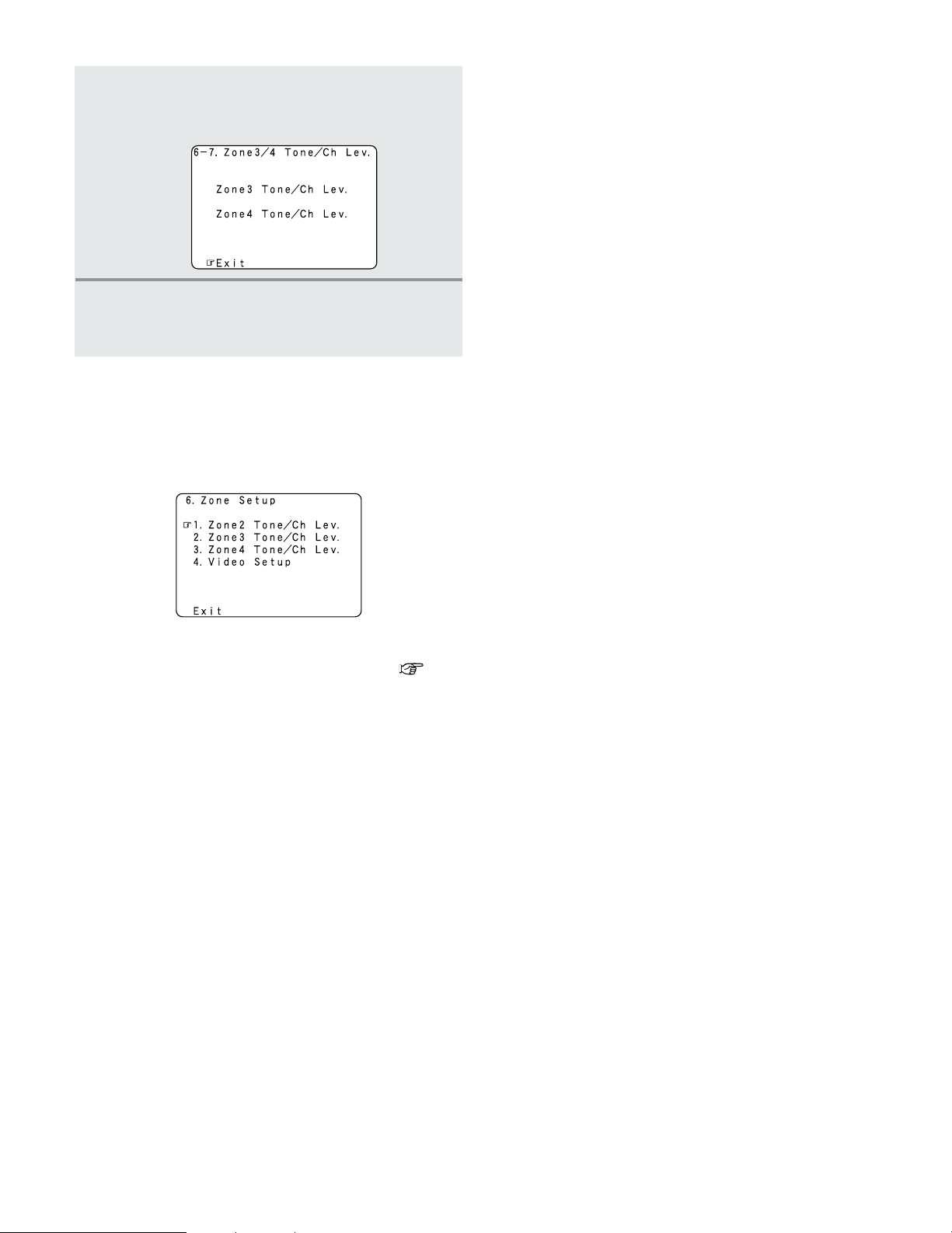
125
Advanced Setup – Part 1
Press the CURSOR
DD
or
HH
button to select
“Exit”, then press the
ENTER button.
• The “Zone Setup” menu reappears.
5
• “ZONE2 Tone/Ch Lev.” can be set in the same way as
“ZONE3/ZONE4 Tone/Ch Lev.”.
• For instructions on the “Video Setup” (item 4) ( page
123, 124).
2 “Zone Setup” setting when ZONE2 is set to
“STEREO” or “MONO”
• The “Zone Setup” screen shown below is displayed when
“STEREO” or “MONO” is selected for the ZONE2 channel
setting at “Channel Setup”.
Press the CURSOR
DD
or
HH
button to select
“Exit”, then press the
ENTER button.
• The “System Setup Menu” reappears.
6
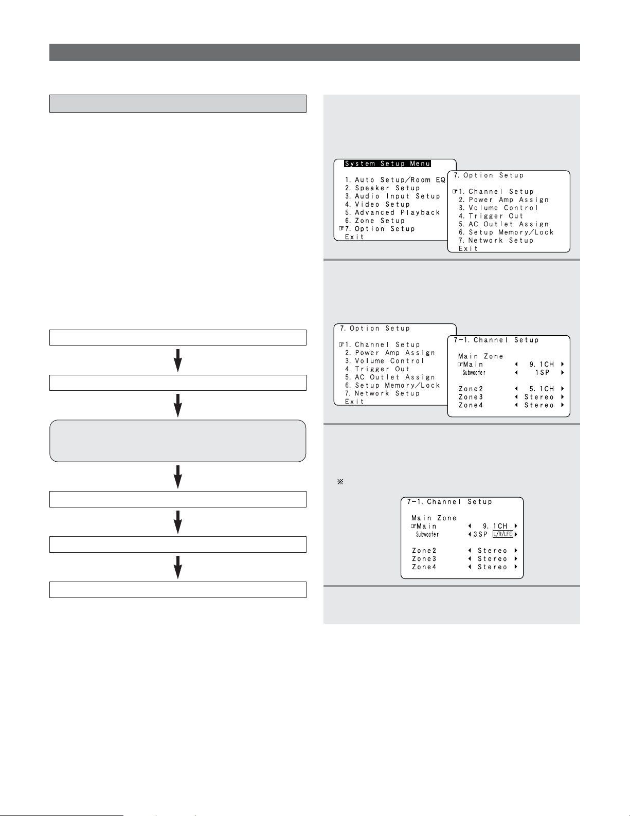
126
Advanced Setup – Part 1
Option Setup
•Make other expert settings.
Setting the Channel Setup
•With this setting it is possible to change the number of
channels played in the different zones according to the
purpose.
The AVR-5805CI is equipped with pre-out terminals for a
total of 22 channels.
16 channel of these pre-out terminals can be assigned
between the MAIN ZONE and ZONE2 (Theater). In addition,
up to three channels of subwoofers can be added to the
MAIN ZONE, so subwoofers can be set in the front and back
or at the sides. The number of channels output from the pre-
out terminals exclusively for ZONE2, 3 and 4 can be set to
“MONO” or “STEREO” according to the method of
playback in the various multi-zones.
1
Press the CURSOR
DD
or
HH
button to select
“Option Setup” at the “System Setup Menu”,
then press the
ENTER button.
• The “Option Setup” menu appears.
3
Press the CURSOR
DD
or
HH
button to select the
zone, then press the
CURSOR
FF
or
GG
button to
select the channel setting.
Refer to the table on page 127.
4
Press the ENTER button to enter the setting.
• The “Option Setup” menu reappears.
2
Press the CURSOR
DD
or
HH
button to select
“Channel Setup”, then press the
ENTER
button.
• The “Channel Setup” screen appears.
2 Channel setup flow
Set the number of channels for the MAIN ZONE’s main channel.
The number of channels that can be set for ZONE2 depends of the
number of channels in the MAIN ZONE. See the table on page 127.
Set the number of subwoofer channels for the MAIN ZONE.
Set the number of channels for the ZONE2.
Set the number of channels for the ZONE3.
Set the number of channels for the ZONE4.
127
Advanced Setup – Part 1
2 The subwoofer output composition is as shown below.
Subwoofer Output Composition
1 SP
– Select this when only one subwoofer is connected.
L/R Select this when subwoofers are installed on the left and right.
F/B Select this when subwoofers are installed at the front and rear.
2 SP
LFE/M
Select this to use the subwoofer for both the main channel’s low frequencies and for LFE
low frequencies.
L/R/LFE
Select this when subwoofers are installed on the left and right and you are using a
subwoofer specifically for the LFE.
F/B/LFE
Select this when subwoofers are installed at the front and rear and you are using a
subwoofer specifically for the LFE.
3 SP
2 The number of channels that can be selected for the different zones is as shown below.
MAIN ZONE
Main Subwoofer
ZONE2 ZONE4
ZONE3
5.1 CH 1 SP 7.1 CH / 5.1 CH / STEREO / MONO STEREO / MONO STEREO / MONO
2 SP 7.1 CH / 5.1 CH / STEREO / MONO STEREO / MONO STEREO / MONO
3 SP 7.1 CH / 5.1 CH / STEREO / MONO STEREO / MONO STEREO / MONO
7.1 CH 1 SP 7.1 CH / 5.1 CH / STEREO / MONO STEREO / MONO STEREO / MONO
2 SP 5.1 CH / STEREO / MONO STEREO / MONO STEREO / MONO
3 SP 5.1 CH / STEREO / MONO STEREO / MONO STEREO / MONO
9.1 CH 1 SP 5.1 CH / STEREO / MONO STEREO / MONO STEREO / MONO
2 SP STEREO / MONO STEREO / MONO STEREO / MONO
3 SP STEREO / MONO STEREO / MONO STEREO / MONO
NOTE:
• The channel settings that can be selected for ZONE2 depend on the channel settings for the MAIN ZONE.
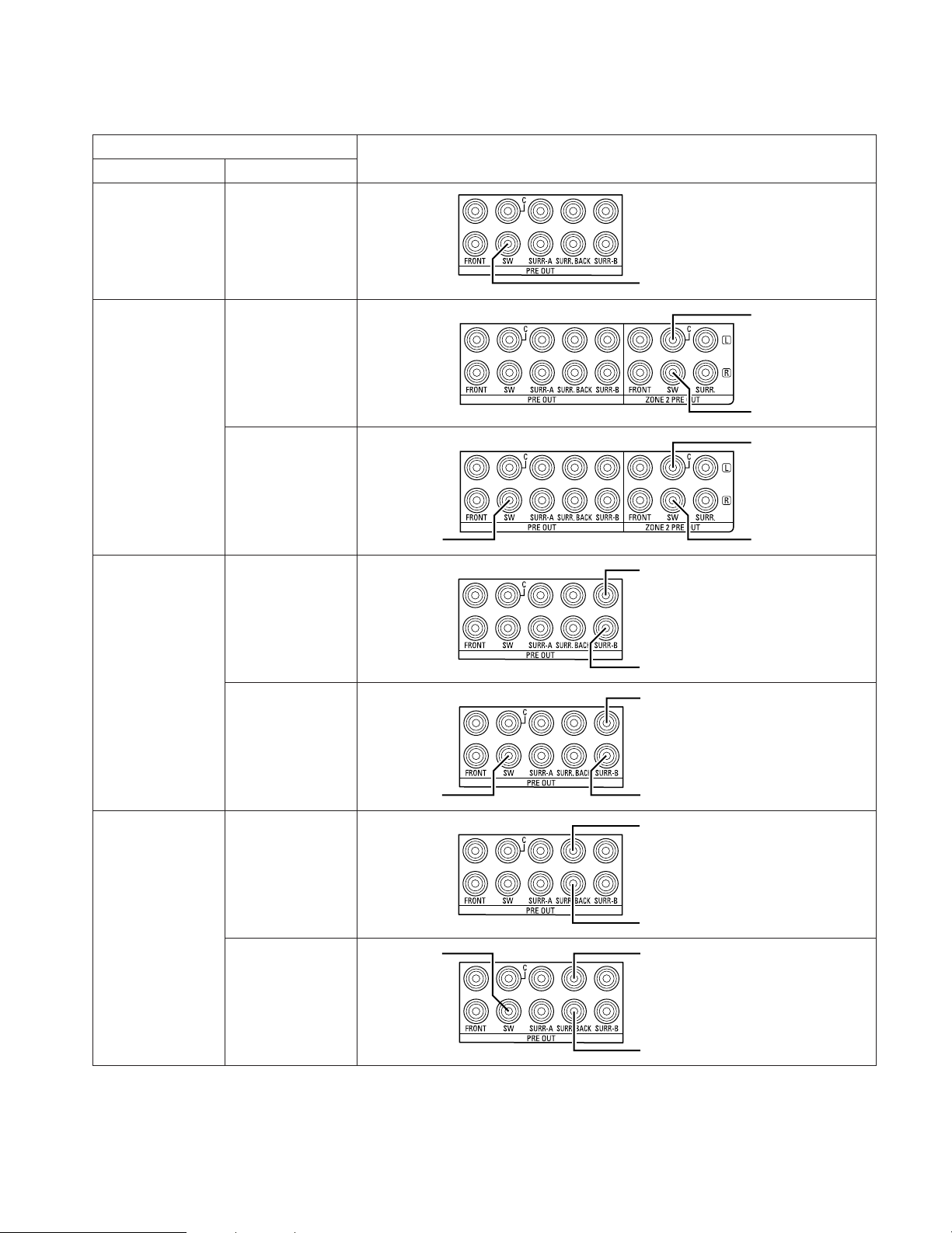
128
Advanced Setup – Part 1
2 Connecting the preouts
The pre-out terminals used to connect the subwoofer depends on the MAIN ZONE’s channel setup. Connect as shown on the
diagram below.
9.1 CH / 7.1 CH /
5.1 CH
1 SP
Channel Setup
Main Subwoofer
Connection
Subwoofer
5.1 CH 2 SP
Subwoofer(R/B/LFE)
Subwoofer(L/F/M)
3 SP
Subwoofer(R/B)
Subwoofer(L/F)LFE
7.1 CH 2 SP
Subwoofer(R/B/LFE)
Subwoofer(L/F/M)
3 SP
Subwoofer(R/B)
Subwoofer(L/F)
LFE
9.1 CH 2 SP
Subwoofer(R/B/LFE)
Subwoofer(L/F/M)
3 SP
Subwoofer(R/B)
Subwoofer(L/F)
LFE
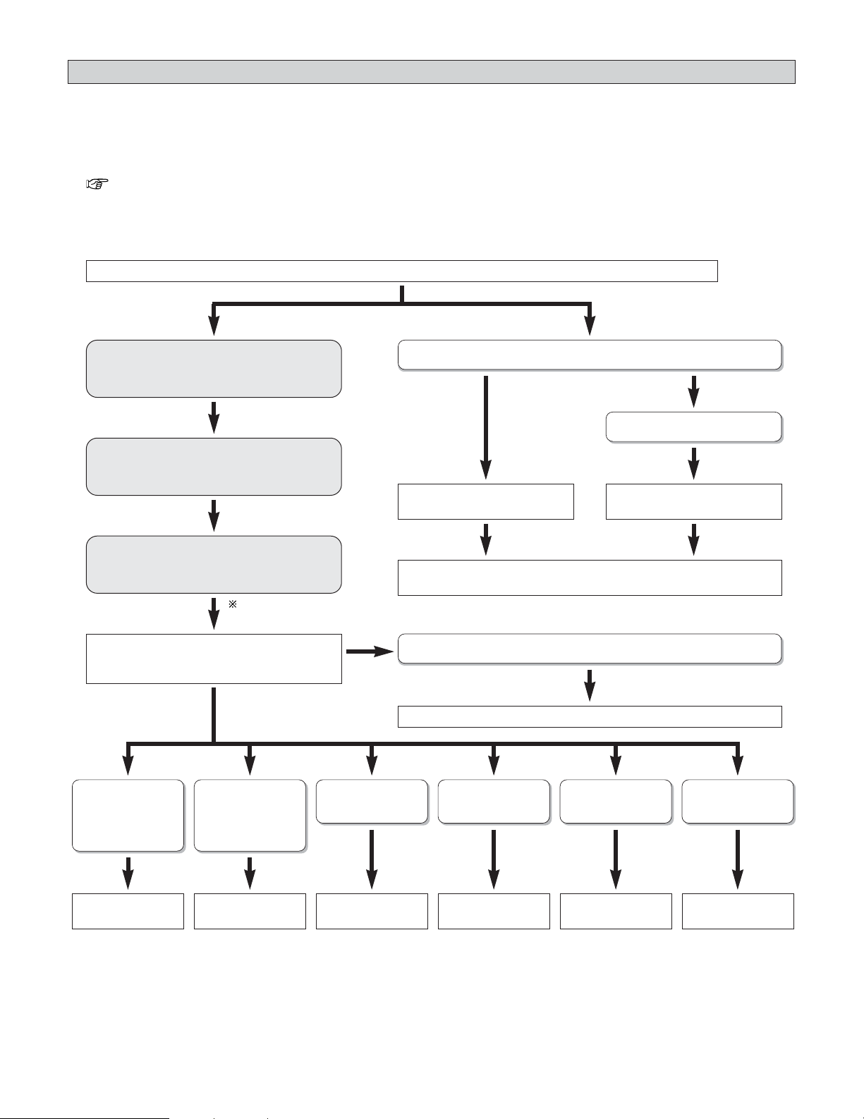
129
Advanced Setup – Part 1
Setting the Power Amplifier Assignment
•With the AVR-5805CI’s 10-channel power amplifier, it is possible to select 10 channels worth of signals (not including the
subwoofer signals output from the pre-out terminals) to be output from the speakers. This makes it possible to put together
various speaker systems. The channels can be selected freely, so “L1” to “L5” and “R1” to “R5” are indicated on the speaker
terminals on the AVR-5805CI’s rear panel.
• The channels for which the power amplifier can be assigned differ according to the channel settings made at “Channel Setup”
( page 126 ~ 128).
Determine what speaker system configuration you want.
2 Power amplifier assignment flow
Signals are output from the speakers with
priority for the MAIN ZONE channels.
(a)
Assign the power amplifier to the MAIN ZONE
channels set at “Channel Setup”.
The number of free power amplifiers depends
on the setting at (b).
(b)
(c)
Decide what to output to the free power
amplifiers at (c).
Selecting the speaker outputs freely
Using front B
Select “Adv+Front B”.Select “Advanced”.
Set what channels to assign the power amplifier to.
Select “Normal ”.
Bi-Amp output of
MAIN ZONE front
channel only
Bi-Amp output of
MAIN ZONE
channels
Output ZONE2 Output ZONE3 Output ZONE4 Output ZONE2/3/4
Select
“Bi-Amp Front”.
Select “Bi-Amp”. Select “+Zone2”. Select “+Zone3”. Select “+Zone4”. Select
“+Zone2/3/4”.
If you do not want to output anything
From (a) to (c) will be done
automatically.
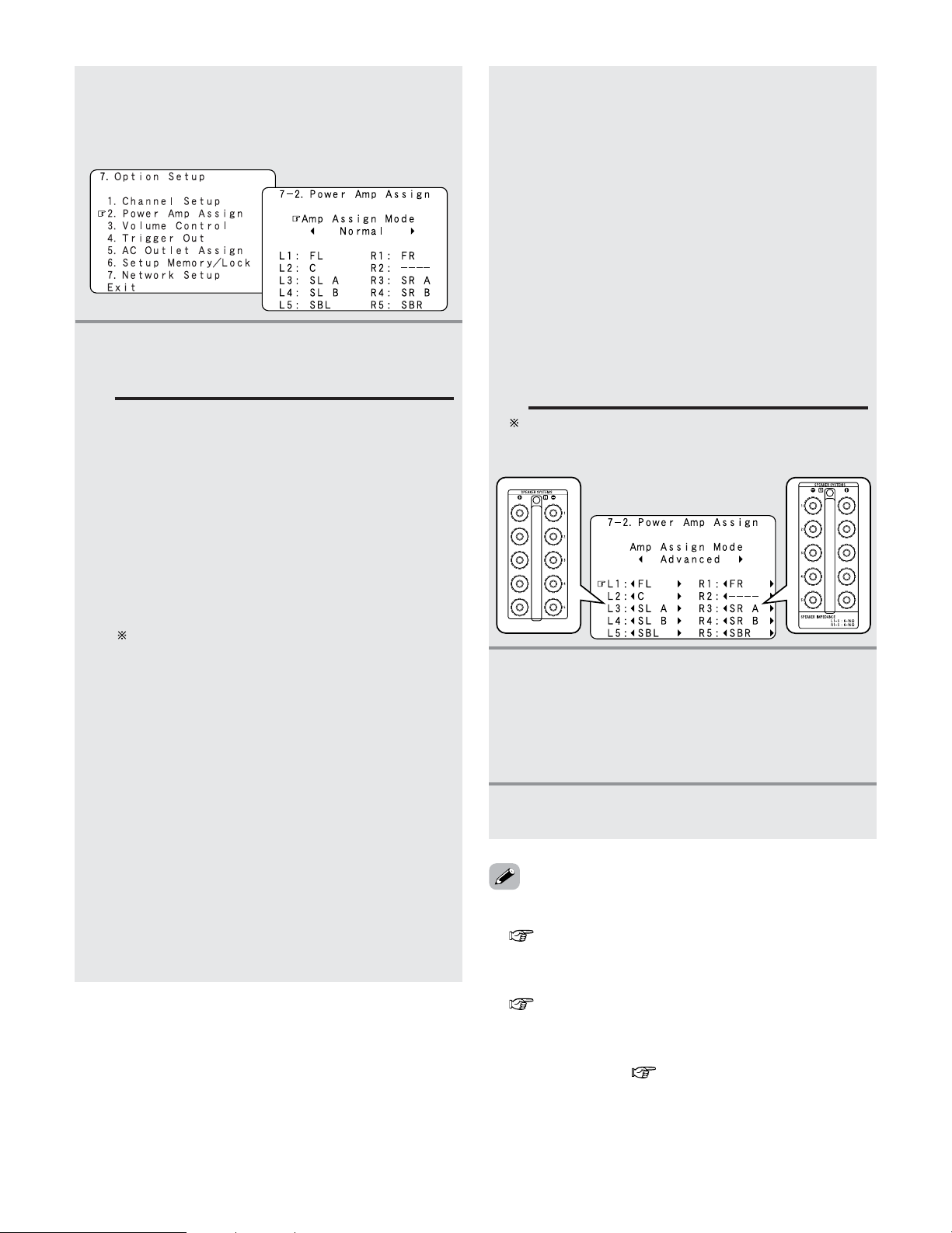
130
Advanced Setup – Part 1
4
Press the ENTER button to enter the setting.
• The “Option Setup” menu reappears.
1
Press the CURSOR
DD
or
HH
button to select
“Power Amp Assign” at the “Option Setup”
menu, then press the
ENTER button.
• The “Power Amp Assign” screen appears.
2
Press the CURSOR
FF
or
GG
button to select the
Amp Assign mode according to the speaker
system you want to achieve.
Normal:
This is the recommended amplifier assignment
mode. Normally select this when not conducting
the power amplifier assignment.
By default, this is set to “Normal”.
Advanced:
With this mode, the power amplifiers can be
assigned freely to the desired channels according
to the speaker system you are using.
Adv+Front B:
With this mode, the power amplifiers can be
assigned freely to the desired channels and front B.
The following modes can be selected when there
are power amplifiers that are free with respect to
the recommended amplifier assignment mode
(“Normal”).
+Zone2:
This mode is the setting of the status in which the
power amplifier is assigned to the ZONE2 output
channel.
+Zone3:
This mode is the setting of the status in which the
power amplifier is assigned to the ZONE3 output
channel.
+Zone4:
This mode is the setting of the status in which the
power amplifier is assigned to the ZONE4 output
channel.
+Zone2/3:
This mode is the setting of the status in which the
power amplifier is assigned simultaneously to the
ZONE2 and 3 output channels.
+Zone3/4:
This mode is the setting of the status in which the
power amplifier is assigned simultaneously to the
ZONE3 and 4 output channels.
+Zone2/4:
This mode is the setting of the status in which the
power amplifier is assigned simultaneously to the
ZONE2 and 4 output channels.
+Zone2/3/4:
This mode is the setting of the status in which the
power amplifier is assigned simultaneously to the
ZONE2, 3 and 4 output channels.
Bi-Amp+Front:
This mode is the setting for playing the front
channel with bi–amp connections.
Bi-Amp:
This mode is the setting for playing the front,
center and surround channels with bi–amp
connections.
• The amplifier assignment modes that can be selected differ
according to the channel settings made at “Channel Setup”
( page 126 ~ 128).
• The status in which power amplifiers are assigned to output
channels in the different amplifier assignment modes differs
according to the channel settings for the different zones
( page 131, 132).
• If the “Advanced” or “Adv+Front B” amplifier assignment
mode is selected, the channels to which power amplifiers
can be assigned differ according to the channel settings for
the different zones ( page 133).
3
When “Advanced” or “Adv+Front B” is
selected:
Press the
CURSOR
DD
or
HH
button to select the
power amplifier to be assigned, then press the
CURSOR
FF
or
GG
button to select which channel
to assigned the amplifier to.
When “Advanced” or “Adv+Front B” is selected, the
power amplifiers can be assigned freely to the desired
channels.
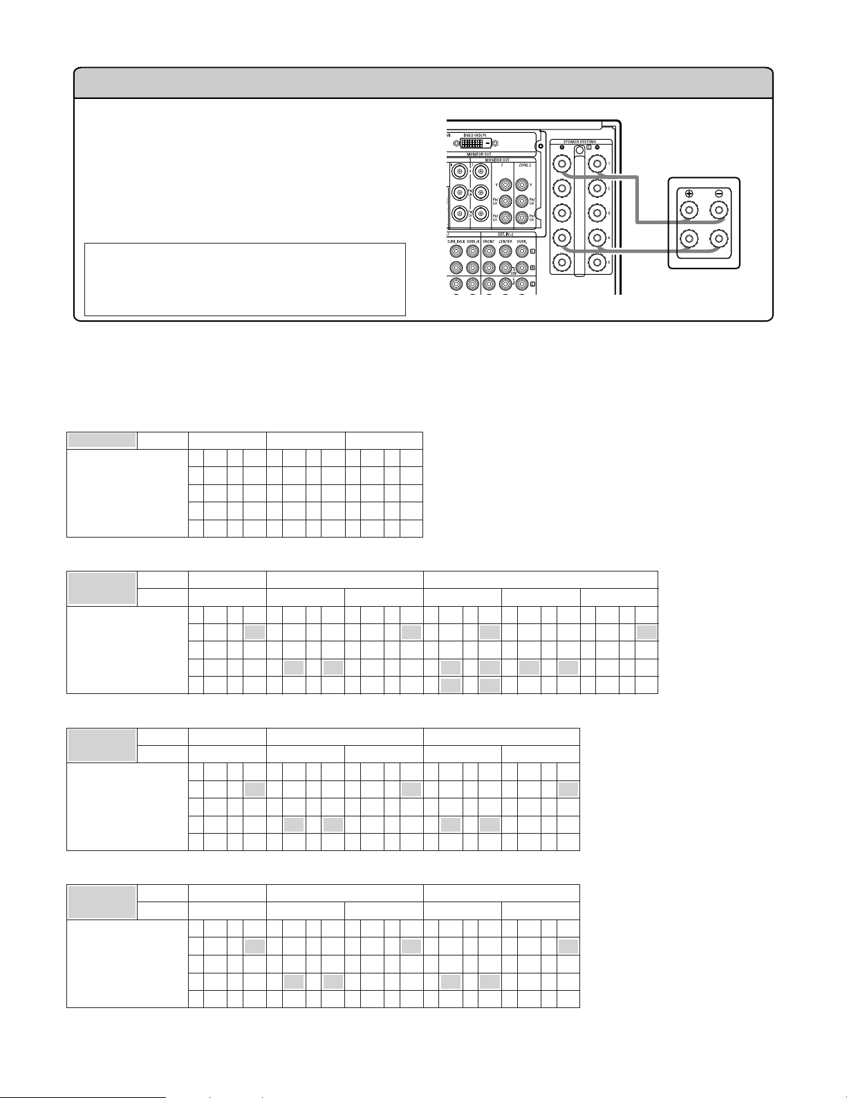
131
Advanced Setup – Part 1
Bi-Amp connections
Certain loudspeakers are equipped with two sets of input
terminals, for bi-amplification. The AVR-5805CI Amp
Assign mode allows you to power bi-amp-capable
speakers with two amplifier channels, up to a total of 5 bi-
amplified speakers in a system using all 10 of the AVR-
5805CI amplifier channels. Be sure to consult the
operating instructions of your bi-amp-capable speakers for
further information before proceeding.
AVR-5805CI
SPEAKER
NOTE:
• When making bi-amp connections, be sure to
remove the short-circuiting bar included with the
speaker.
2
Table of power amplifier assignment modes with respect to the channel settings for the different zones
and assignment modes
• Amp Assign mode: Normal
Channel Setup /
Power Amp Assign
MAIN ZONE
L1
9.1 CH
FL R1 FR
L2 C R2 –
L3 SL A R3 SR A
L4 SL B R4 SR B
L5 SBL R5 SBR
L1
7.1 CH
FL R1 FR
L2 C R2 –
L3 SL A R3 SR A
L4 – R4 –
L5 SBL R5 SBR
L1
5.1 CH
FL R1 FR
L2 C R2–
L3 SL A R3 SR A
L4 – R4–
L5 – R5–
• Amp Assign mode: +ZONE4
Channel Setup /
Power Amp Assign
MAIN ZONE 9.1 CH
ZONE4 MONO
L1
FL R1 FR
L2 C R2
Z4 M
L3 SL A R3 SR A
L4 SL B R4 SR B
L5 SBL R5 SBR
7.1 CH
STEREO
L1
FL R1 FR
L2 C R2 –
L3 SL A R3 SR A
L4
Z4 L R4 Z4 R
L5 SBL R5 SBR
MONO
L1
FL R1 FR
L2 C R2
Z4 M
L3 SL A R3 SR A
L4 – R4–
L5 SBL R5 SBR
5.1 CH
STEREO
L1
FL R1 FR
L2 C R2–
L3 SL A R3 SR A
L4
Z4 L R4 Z4 R
L5 – R5–
MONO
L1
FL R1 FR
L2 C R2
Z4 M
L3 SL A R3 SR A
L4 – R4 –
L5 – R5 –
• Amp Assign mode: +ZONE2
Channel Setup /
Power Amp Assign
MAIN ZONE 9.1 CH
ZONE2 MONO
L1
FL R1 FR
L2 C R2
Z2 M
L3 SL A R3 SR A
L4 SL B R4 SR B
L5 SBL R5 SBR
7.1 CH
STEREO
L1
FL R1 FR
L2 C R2 –
L3 SL A R3 SR A
L4
Z2 L R4 Z2 R
L5 SBL R5 SBR
MONO
L1
FL R1 FR
L2 C R2
Z2 M
L3 SL A R3 SR A
L4 – R4–
L5 SBL R5 SBR
5.1 CH
L1
FL R1 FR
L2 C R2
Z2 C
L3 SL A R3 SR A
L4
Z2 FL
R4
Z2 FR
L5
Z2 SL
R5
Z2 SR
5.1 CH
STEREO
L1
FL R1 FR
L2 C R2 –
L3 SL A R3 SR A
L4
Z2 L R4 Z2 R
L5 – R5 –
MONO
L1
FL R1 FR
L2 C R2
Z2 M
L3 SL A R3 SR A
L4 – R4–
L5 – R5–
• Amp Assign mode: +ZONE3
Channel Setup /
Power Amp Assign
MAIN ZONE 9.1 CH
ZONE3 MONO
L1
FL R1 FR
L2 C R2
Z3 M
L3 SL A R3 SR A
L4 SL B R4 SR B
L5 SBL R5 SBR
7.1 CH
STEREO
L1
FL R1 FR
L2 C R2 –
L3 SL A R3 SR A
L4
Z3 L R4 Z3 R
L5 SBL R5 SBR
MONO
L1
FL R1 FR
L2 C R2
Z3 M
L3 SL A R3 SR A
L4 – R4–
L5 SBL R5 SBR
5.1 CH
STEREO
L1
FL R1 FR
L2 C R2–
L3 SL A R3 SR A
L4
Z3 L R4 Z3 R
L5 – R5–
MONO
L1
FL R1 FR
L2 C R2
Z3 M
L3 SL A R3 SR A
L4 – R4 –
L5 – R5 –
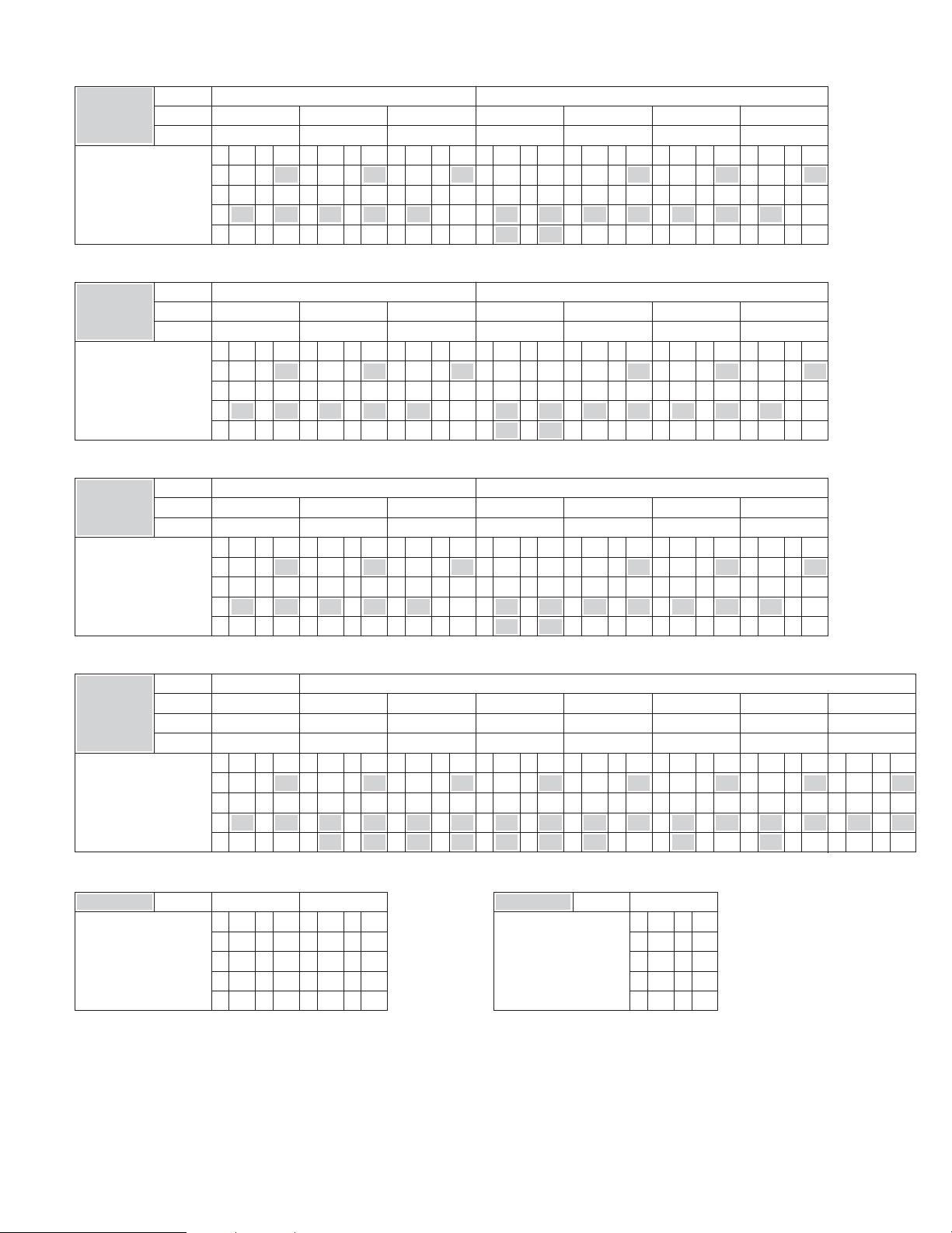
132
Advanced Setup – Part 1
• Amp Assign mode: +ZONE2/3
Channel Setup /
Power Amp Assign
MAIN ZONE
ZONE2
L1
FL R1 FR
L2 C R2
Z3 M
L3 SL A R3 SR A
L4 Z2 L R4 Z2 R
L5 SBL R5 SBR
7.1 CH
MONO
L1
FL R1 FR
L2 C R2
Z2 M
L3 SL A R3 SR A
L4 Z3 L R4 Z3 R
L5 SBL R5 SBR
MONO
L1
FL R1 FR
L2 C R2
Z3 M
L3 SL A R3 SR A
L4 Z2 M R4 –
L5 SBL R5 SBR
STEREO
L1
FL R1 FR
L2 C R2–
L3 SL A R3 SR A
L4
Z2 L R4 Z2 R
L5
Z3 L R5 Z3 R
5.1 CH
STEREO
L1
FL R1 FR
L2 C R2
Z3 M
L3 SL A R3 SR A
L4 Z2 L R4 Z2 R
L5 – R5 –
MONO
L1
FL R1 FR
L2 C R2
Z2 M
L3 SL A R3 SR A
L4 Z3 L R4 Z3 R
L5 – R5–
STEREO
MONO
ZONE3 STEREO MONO STEREO MONO STEREOMONO MONO
L1
FL R1 FR
L2 C R2
Z3 M
L3 SL A R3 SR A
L4 Z2 M R4 –
L5 – R5 –
• Amp Assign mode: +ZONE3/4
Channel Setup /
Power Amp Assign
MAIN ZONE
ZONE3
L1
FL R1 FR
L2 C R2
Z4 M
L3 SL A R3 SR A
L4
Z3 L R4 Z3 R
L5 SBL R5 SBR
7.1 CH
MONO
L1
FL R1 FR
L2 C R2
Z3 M
L3 SL A R3 SR A
L4
Z4 L R4 Z4 R
L5 SBL R5 SBR
MONO
L1
FL R1 FR
L2 C R2
Z4 M
L3 SL A R3 SR A
L4
Z3 M R4 –
L5 SBL R5 SBR
STEREO
L1
FL R1 FR
L2 C R2–
L3 SL A R3 SR A
L4
Z3 L R4 Z3 R
L5
Z4 L R5 Z4 R
5.1 CH
STEREO
L1
FL R1 FR
L2 C R2
Z4 M
L3 SL A R3 SR A
L4
Z3 L R4 Z3 R
L5 – R5 –
MONO
L1
FL R1 FR
L2 C R2
Z3 M
L3 SL A R3 SR A
L4
Z4 L R4 Z4 R
L5 – R5–
STEREO
MONO
ZONE4 STEREO
MONO
STEREO MONO
STEREO
MONO MONO
L1
FL R1 FR
L2 C R2
Z4 M
L3 SL A R3 SR A
L4
Z3 M R4 –
L5 – R5 –
• Amp Assign mode: +ZONE2/4
Channel Setup /
Power Amp Assign
MAIN ZONE
ZONE2
L1
FL R1 FR
L2 C R2
Z4 M
L3 SL A R3 SR A
L4
Z2 L R4 Z2 R
L5 SBL R5 SBR
7.1 CH
MONO
L1
FL R1 FR
L2 C R2
Z2 M
L3 SL A R3 SR A
L4
Z4 L R4 Z4 R
L5 SBL R5 SBR
MONO
L1
FL R1 FR
L2 C R2
Z4 M
L3 SL A R3 SR A
L4
Z2 M R4 –
L5 SBL R5 SBR
STEREO
L1
FL R1 FR
L2 C R2–
L3 SL A R3 SR A
L4
Z2 L R4 Z2 R
L5
Z4 L R5 Z4 R
5.1 CH
STEREO
L1
FL R1 FR
L2 C R2
Z4 M
L3 SL A R3 SR A
L4
Z2 L R4 Z2 R
L5 – R5 –
MONO
L1
FL R1 FR
L2 C R2
Z2 M
L3 SL A R3 SR A
L4
Z4 L R4 Z4 R
L5 – R5–
STEREO
MONO
ZONE4 STEREO MONO STEREO MONO STEREOMONO MONO
L1
FL R1 FR
L2 C R2
Z4 M
L3 SL A R3 SR A
L4
Z2 M R4 –
L5 – R5 –
• Amp Assign mode: Bi-Amp Front
Channel Setup /
Power Amp Assign
MAIN ZONE
L1
7.1 CH
FL R1 FR
L2 C R2 –
L3 SL A R3 SR A
L4 FL R4 FR
L5 SBL R5 SBR
L1
5.1 CH
FL R1 FR
L2 C R2 –
L3 SL A R3 SR A
L4 FL R4 FR
L5 – R5 –
• Amp Assign mode: Bi-Amp
Channel Setup /
Power Amp Assign
MAIN ZONE
L1
5.1 CH
FL R1 FR
L2 C R2 C
L3 SL A R3 SR A
L4 FL R4 FR
L5 SL A R5 SR A
• Amp Assign mode: +ZONE2/3/4
Channel Setup /
Power Amp Assign
MAIN ZONE
ZONE2
L1
FL R1 FR
L2 C R2
Z2 M
L3 SL A R3 SR A
L4
Z3 M R4 Z4 M
L5 SBL R5 SBR
7.1 CH
STEREO
L1
FL R1 FR
L2 C R2
Z4 M
L3 SL A R3 SR A
L4
Z2 L R4 Z2 R
L5
Z3 L R5 Z3 R
STEREO
L1
FL R1 FR
L2 C R2
Z3 M
L3 SL A R3 SR A
L4
Z2 L R4 Z2 R
L5
Z4 L R5 Z4 R
MONO
L1
FL R1 FR
L2 C R2
Z2 M
L3 SL A R3 SR A
L4
Z3 L R4 Z3 R
L5
Z4 L R5 Z4 R
5.1 CH
STEREO
L1
FL R1 FR
L2 C R2
Z3 M
L3 SL A R3 SR A
L4
Z2 L R4 Z2 R
L5
Z4 M R5 –
MONO
L1
FL R1 FR
L2 C R2
Z2 M
L3 SL A R3 SR A
L4
Z3 L R4 Z3 R
L5
Z4 M R5 –
MONO
MONO
ZONE3 STEREO MONO STEREO MONO STEREOMONO MONO
L1
FL R1 FR
L2 C R2
Z2 M
L3 SL A R3 SR A
L4
Z4 L R4 Z4 R
L5
Z3 M R5 –
ZONE4 MONO STEREO STEREO MONO MONOMONO STEREO
MONO
MONO
L1
FL R1 FR
L2 C R2
Z2 M
L3 SL A R3 SR A
L4
Z3 M R4 Z4 M
L5 – R5 –
MONO
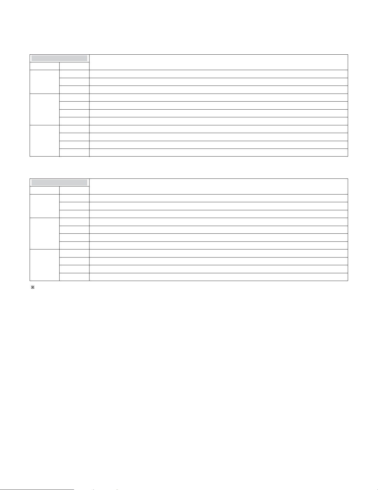
133
Advanced Setup – Part 1
2 Table of channels to which power amplifiers can be assigned with respect to the channel settings for
the different zones and the amplifier assignment modes
• Amp Assign mode: Advanced
Channel Setup ↓
MAIN ZONE
ASSIGNABLE CHANNEL
FL, FR, C, SL A, SR A, SL B, SR B, SBL, SBR, Z2 FL, Z2 FR, Z2 C, Z2 SL, Z2 SR, Z3 L, Z3 R, Z4 L, Z4 R
FL, FR, C, SL A, SR A, SL B, SR B, SBL, SBR, Z2 L, Z2 R, Z3 L, Z3 R, Z4 L, Z4 R
FL, FR, C, SL A, SR A, SL B, SR B, SBL, SBR, Z2 M, Z3 L, Z3 R, Z4 L, Z4 R
ZONE2
9.1 CH 5.1CH
STEREO
MONO
FL, FR, C, SL A, SR A, SBL, SBR, Z2 FL, Z2 FR, Z2 C, Z2 SL, Z2 SR, Z2 SBL, Z2 SBR, Z3 L, Z3 R, Z4 L, Z4 R
FL, FR, C, SL A, SR A, SBL, SBR, Z2 L, Z2 R, Z3 L, Z3 R, Z4 L, Z4 R
FL, FR, C, SL A, SR A, SBL, SBR, Z2 M, Z3 L, Z3 R, Z4 L, Z4 R
7.1 CH 7.1CH
STEREO
MONO
FL, FR, C, SL A, SR A, SBL, SBR, Z2 FL, Z2 FR, Z2 C, Z2 SL, Z2 SR, Z3 L, Z3 R, Z4 L, Z4 R5.1CH
FL, FR, C, SL A, SR A, Z2 FL, Z2 FR, Z2 C, Z2 SL, Z2 SR, Z2 SBL, Z2 SBR, Z3 L, Z3 R, Z4 L, Z4 R
FL, FR, C, SL A, SR A, Z2 L, Z2 R, Z3 L, Z3 R, Z4 L, Z4 R
FL, FR, C, SL A, SR A, Z2 M, Z3 L, Z3 R, Z4 L, Z4 R
5.1 CH 7.1CH
STEREO
MONO
FL, FR, C, SL A, SR A, Z2 FL, Z2 FR, Z2 C, Z2 SL, Z2 SR, Z3 L, Z3 R, Z4 L, Z4 R5.1CH
• Amp Assign mode: Adv+Front B
Channel Setup ↓
MAIN ZONE
ASSIGNABLE CHANNEL
FL A, FR A, FL B, FR B, C, SL A, SR A, SL B, SR B, SBL, SBR, Z2 FL, Z2 FR, Z2 C, Z2 SL, Z2 SR, Z3 L, Z3 R, Z4 L, Z4 R
FL A, FR A, FL B, FR B, C, SL A, SR A, SL B, SR B, SBL, SBR, Z2 L, Z2 R, Z3 L, Z3 R, Z4 L, Z4 R
FL A, FR A, FL B, FR B, C, SL A, SR A, SL B, SR B, SBL, SBR, Z2 M, Z3 L, Z3 R, Z4 L, Z4 R
ZONE2
9.1 CH 5.1CH
STEREO
MONO
FL A, FR A, FL B, FR B, C, SL A, SR A, SBL, SBR, Z2 FL, Z2 FR, Z2 C, Z2 SL, Z2 SR, Z2 SBL, Z2 SBR, Z3 L, Z3 R, Z4 L, Z4 R
FL A, FR A, FL B, FR B, C, SL A, SR A, SBL, SBR, Z2 L, Z2 R, Z3 L, Z3 R, Z4 L, Z4 R
FL A, FR A, FL B, FR B, C, SL A, SR A, SBL, SBR, Z2 M, Z3 L, Z3 R, Z4 L, Z4 R
7.1 CH 7.1CH
STEREO
MONO
FL A, FR A, FL B, FR B, C, SL A, SR A, SBL, SBR, Z2 FL, Z2 FR, Z2 C, Z2 SL, Z2 SR, Z3 L, Z3 R, Z4 L, Z4 R5.1CH
FL A, FR A, FL B, FR B, C, SL A, SR A, Z2 FL, Z2 FR, Z2 C, Z2 SL, Z2 SR, Z2 SBL, Z2 SBR, Z3 L, Z3 R, Z4 L, Z4 R
FL A, FR A, FL B, FR B, C, SL A, SR A, Z2 L, Z2 R, Z3 L, Z3 R, Z4 L, Z4 R
FL A, FR A, FL B, FR B, C, SL A, SR A, Z2 M, Z3 L, Z3 R, Z4 L, Z4 R
5.1 CH 7.1CH
STEREO
MONO
FL A, FR A, FL B, FR B, C, SL A, SR A, Z2 FL, Z2 FR, Z2 C, Z2 SL, Z2 SR, Z3 L, Z3 R, Z4 L, Z4 R5.1CH
The above is an example of the selectable channels when “STEREO” is set for the ZONE3 and 4 channel setting.
If “MONO” is selected, “Z3 M” and “Z4 M” are displayed.
134
Advanced Setup – Part 1
Volume Limit:
Set the upper limit for the volume for the different
zones.
• –20 dB, –10 dB, 0 dB:
The volume cannot be increased above the
selected levels.
• OFF:
If you do not want to set a volume limit, select
“OFF”.
In this case, the volume can be set to the AVR-
5805CI’s maximum volume (output) level of +18
dB, which is extremely loud.
2
Press the CURSOR
DD
or
HH
button to select the
desired setting, then press the
CURSOR
FF
or
GG
button to select the parameter.
Setting the Volume Control
• Set the upper limit for the volume, the volume level when
the power is turned on, and the volume level when the mute
mode is set for the each zones.
1
Press the CURSOR
DD
or
HH
button to select
“Volume Control” at the “Option Setup”
menu, then press the
ENTER button.
• The “Volume Control” screen appears.
Power On Level:
Set the volume that is set when the power is
turned on for the different zones.
You can adjust the volume level within the range of
–80 to +18 dB in steps of 1.0 dB.
• – – – (Mute)
The volume is always muted when the power is
turned on.
• LAST
The volume set when the AVR-5805CI was last
used is stored in the memory and set when the
power is turned on.
3
Press the ENTER button to enter the setting.
• The “Option Setup” menu reappears.
Mute Level:
Set the volume attenuation level when the mute
mode is set for the different zones.
• FULL
The volume is fully muted.
• –40 dB
The volume is lowered 40 dB from the current
level.
• –20 dB
The volume is lowered 20 dB from the current
level.
Volume Level:
Set whether to fix the output level for the different
zones or make it variable.
• VAR (variable)
The level can be adjusted freely using buttons on
the remote control unit.
• –40 dB, 0 dB
The output level is fixed at the set level and the
volume can no longer be adjusted.
• For ZONE2, ZONE3 and ZONE4 the “Volume Limit” and
“Power On Level” can be set when “Variable” is selected
for “Volume Level”.
•When the power amplifier is assigned to either of the
ZONE2, ZONE3 and ZONE4 channels at “Power Amp
Assign”, “–VAR–” (only variable) is displayed and the fixed
level cannot be set.
135
Advanced Setup – Part 1
Setting the Trigger Out
• Four 12 V DC Trigger Outputs on the rear panel can be used
to control other devices with compatible trigger inputs, such
as motorized screens, motorized screen masking, motorized
drapes, and other trigger-controlled devices.
• Set the DC output supplied from the trigger out jacks for the
various input sources to “ON” or “OFF”.
1
Press the CURSOR
DD
or
HH
button to select
“Trigger Out” at the “Option Setup” menu,
then press the
ENTER button.
• The “Trigger Out” screen appears.
2
Press the CURSOR
DD
or
HH
button to select the
trigger out terminal you want to set, then press
the
ENTER button.
•Switch to the setting screen.
Example: When “Trigger Out 1” is selected
3
Press the CURSOR
FF
or
GG
button to select the
zone (MAIN ZONE, ZONE2, ZONE3 and
ZONE4).
The power supplied from the trigger out terminal turns
on and off when the power for the set zone is turned
on and off.
4
Press the CURSOR
DD
or
HH
button to select the
input source, then press the
CURSOR
FF
or
GG
button to select “ON” or “OFF”.
If “MAIN” was selected at step 3:
Press the
CURSOR
DD
or
HH
button to select the
surround mode, then press the
CURSOR
FF
or
GG
button to select “ON” or “OFF”.
5
ON:
If “ON” is selected when an input source set to
“ON” is selected, the power supplied from the
trigger out terminal turns on.
OFF:
If “OFF” is selected when an input source set to
“ON” is selected, the power supplied from the
trigger out terminal turns off.
6
Press the ENTER button.
• The “Trigger Out” screen reappears.
Use the same procedure to make the settings for
Trigger Out 2, 3, 4.
Press the CURSOR
DD
or
HH
button to select
“Exit”, then press the
ENTER button.
• The “Option Setup” menu reappears.
7
When “Default Yes” is selected, then press the
CURSOR
FF
button to reset to the default values.
ON:
When that input source is selected, the power
supplied from the trigger out terminal turns on.
OFF:
When that input source is selected, the power
supplied from the trigger out terminal turns off.
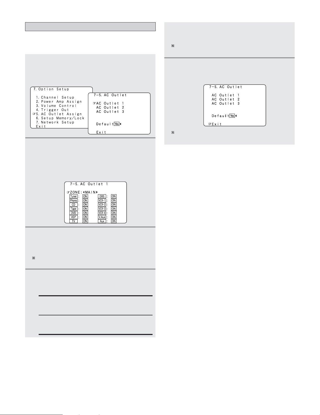
136
Advanced Setup – Part 1
Setting the AC Outlet Assignment
• This sets the AC outlet to on or off for the different input
sources.
1
Press the CURSOR
DD
or
HH
button to select “AC
Outlet Assign” at the “Option Setup” menu,
then press the
ENTER button.
• The “AC Outlet Assign” screen appears.
2
Press the CURSOR
DD
or
HH
button to select the
AC outlet you want to set, then press the
ENTER button.
•Switch to the setting screen.
Example: When “AC Outlet 1” is selected
3
Press the CURSOR
FF
or
GG
button to select the
zone (MAIN ZONE, ZONE2, ZONE3 and
ZONE4).
The power of the AC outlet turns on and off when the
power for the set zone is turned on and off.
4
Press the CURSOR
DD
or
HH
button to select the
input source, then press the
CURSOR
FF
or
GG
button to select “ON” or “OFF”.
ON:
The power of the AC outlet turns on when that
input source is selected.
OFF:
The power of the AC outlet turns off when that
input source is selected.
5
Press the ENTER button.
• The “AC Outlet Assign” screen reappears.
Use the same procedure to make the settings for AC
Outlet 2, 3.
Press the CURSOR
DD
or
HH
button to select
“Exit”, then press the
ENTER button.
• The “Option Setup” menu reappears.
6
When “Default Yes” is selected, then press the
CURSOR
FF
button to reset to the default values.
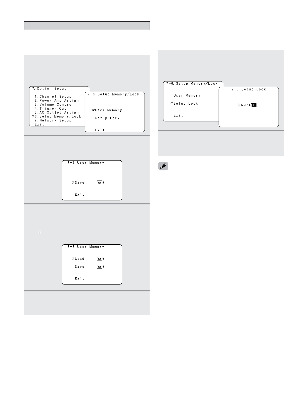
Advanced Setup – Part 1
137
1
Press the CURSOR
DD
or
HH
button to select
“Setup Lock” at the “Setup Memory / Lock”
screen, then press the
ENTER button.
• Switch to the “Setup Lock” screen.
2
Press the CURSOR
FF
button to select “ON”, to
lock the system setup settings, then press the
ENTER button.
Memory backup and protecting the setting
• When the setup lock function is activated, the settings listed
below cannot be changed, and “SETUP LOCKED!” is
displayed when related buttons are operated.
• System setup settings
• Surround parameter settings
•Tone control settings
• Channel level settings (including test tones)
• Room EQ
•To unlock, press the SYSTEM SETUP button again and display
the “Setup Lock” screen, then select “OFF” and press the
ENTER button.
2 Setup Lock
This sets whether or not to lock the system setup settings
so that they cannot be changed.
Once all the settings are made, set “Setup Lock” to “ON”.
2
User Memory
This stores the current user settings in the memory.
1
Press the CURSOR
DD
or
HH
button to select
“Setup Memory / Lock” at the “Option Setup”
menu, then press the
ENTER button.
• The “Setup Memory / Lock” screen appears.
2
Press the CURSOR
DD
or
HH
button to select
“User Memory”, then press the
ENTER button.
• Switch to the “User Memory” screen.
3
Press the CURSOR
FF
button to select “Save Yes”.
• About 30 seconds are required for the settings to be
stored in the memory.
Once the settings are stored in the memory,
“Load” is displayed and the settings can be loaded.
4
Press the CURSOR
DD
or
HH
button to select
“Exit”, then press the
ENTER button.
• The “Setup Memory / Lock” screen reappears.
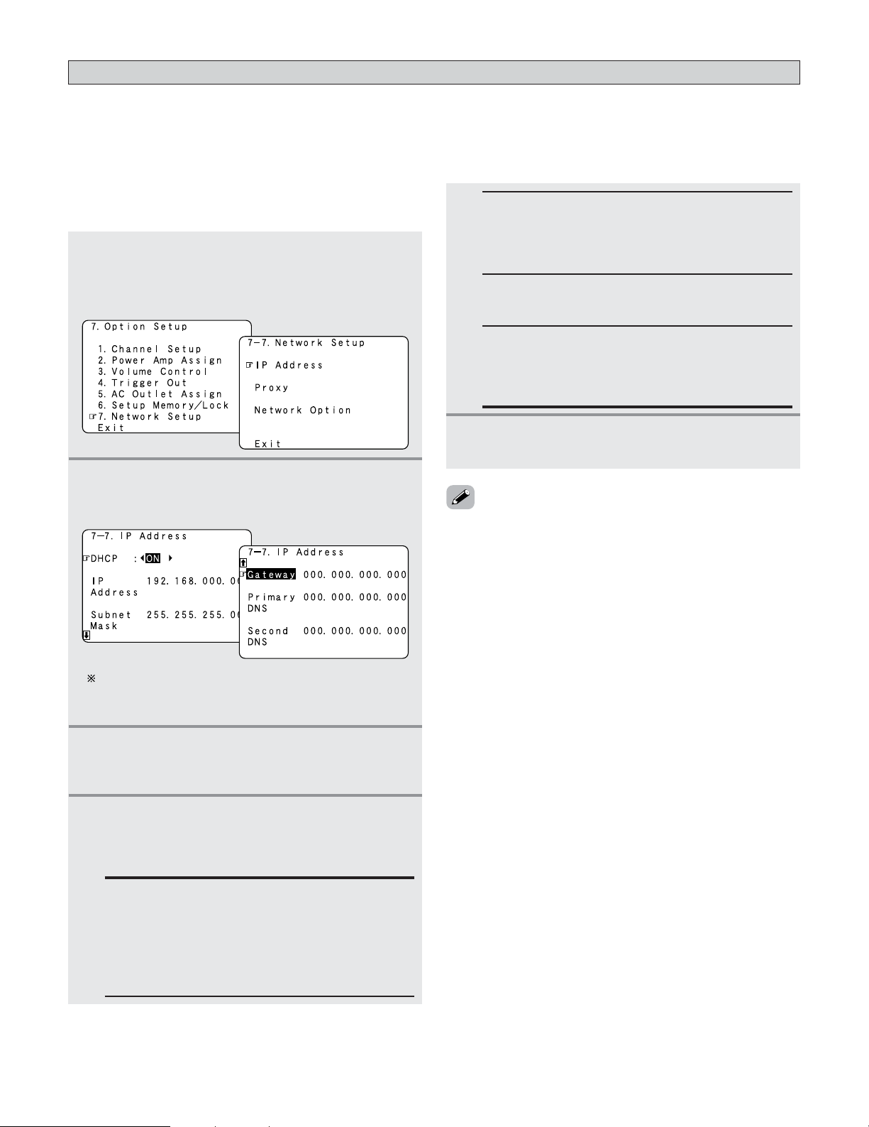
138
Advanced Setup – Part 1
• If you are using a broadband router (DHCP function), there is no need to make the settings at “Setting the IP Address” and
“Setting the Proxy”, since the DHCP function is set to “ON” in the AVR-5805CI’s default settings.
• If the AVR-5805CI is being used connected to a network without the DHCP function, the network settings must be made. In
this case, some knowledge of networks is required.
1
Press the CURSOR
DD
or
HH
button to select
“Network Setup” at the “Option Setup” menu,
then press the
ENTER button.
• The “Network Setup” screen appears.
2
Press the CURSOR
DD
or
HH
button to select “IP
Address”, then press the
ENTER button.
• The “IP Address” screen appears.
3
Press the CURSOR
FF
or
GG
button to select
“OFF”.
• The DHCP function is disabled.
4
Press the CURSOR
DD
or
HH
button to select the
desired setting item, then press the
CURSOR
GG
button and CURSOR
DD
or
HH
button to input
the address.
IP Address:
Set the IP address within the ranges shown below.
The Network Audio function cannot be used if
other IP addresses are set.
CLASS A: 10.0.0.0 ~ 10.255.255.255
CLASS B: 172.16.0.0 ~ 172.31.255.255
CLASS C: 192.168.0.0 ~ 192.168.255.255
Subnet Mask:
When connecting an xDSL modem or terminal
adapter directly to the AVR-5805CI, input the subnet
mask indicated in the documentation supplied by
your provider. Normally input 255.255.255.0.
Gateway:
When connected to a gateway (router), input its IP
address.
Primary DNS / Secondary DNS:
If there is only one DNS address indicated in the
documentation supplied by your provider, input it at
“Primary DNS”. If there are two or more DNS
addresses, input the first one at “Second DNS”.
5
Press the ENTER button to enter the setting.
• The “Network Setup” menu reappears.
• DHCP (Dynamic Host Configuration Protocol):
These are systems by which the IP address and other
network settings are automatically set for the AVR-5805CI,
computer, broadband router and network devices.
• DNS (Domain Name System):
This is a system for converting the domain names used
when browsing Internet sites (for example,
“www.denon.jp”) into the IP addresses actually used for
communications (for example, “202.221.192.106”).
Setting the Network Setup
2 Setting the IP Address
Set this when “OFF” is set for “DHCP”.
The IP address, etc., is not displayed when “DHCP” is
set to “ON” and the unit is not connected to a
network.
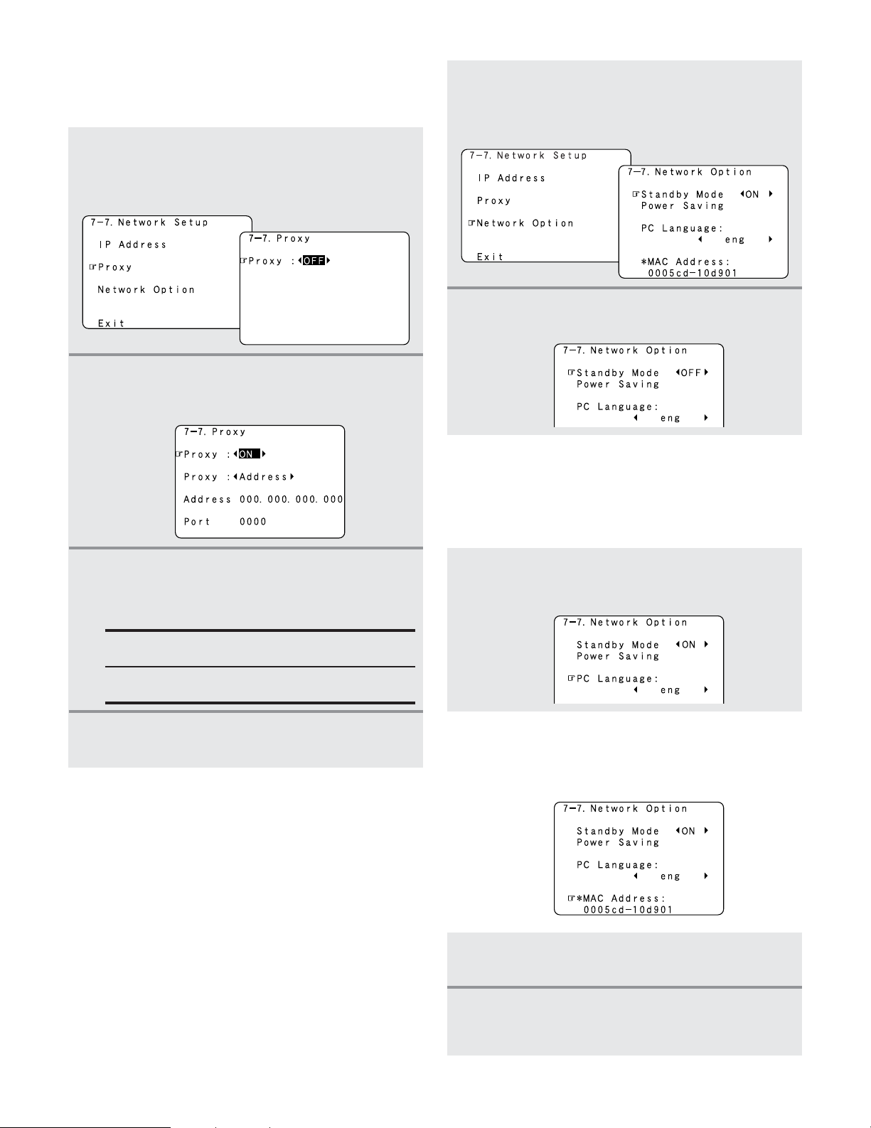
139
Advanced Setup – Part 1
2 Setting the Proxy
Make this setting when connecting to the Internet via a
proxy server.
1
Press the CURSOR
DD
or
HH
button to select
“Proxy” at the “Network Setup” screen, then
press the
ENTER button.
• The “Proxy” screen appears.
2
Press the CURSOR
FF
or
GG
button to select
“ON”.
• The proxy server is enabled.
3
Press the CURSOR
DD
or
HH
button to select the
desired setting item, then press the
CURSOR
GG
button and CURSOR
DD
or
HH
button to input
the character or number.
Proxy:
Input the proxy server domain name or address.
Port:
Input the proxy server port number.
4
Press the ENTER button to enter the setting.
• The “Network Setup” menu reappears.
2 Setting the Network Option
[1] Setting the Power Saving
When not using the AVR-5805CI connected in a network,
set “ON” to reduce the power consumption when in the
standby mode.
Set “OFF” when using the AVR-5805CI connected in a
network.
1
Press the CURSOR
DD
or
HH
button to select
“Network Option” at the “Network Setup”
screen, then press the
ENTER button.
• The “Network Option” screen appears.
2
Press the CURSOR
FF
or
GG
button to select
“ON” or “OFF”.
[2] Setting the PC Language
Select according to the language of the computer being used.
The languages are indicated with three letters conforming
to ISO639-2.
[3] Checking the MAC Address
• The AVR-5805CI’s MAC address is displayed.
• The MAC address differs for each set.
Press the CURSOR
DD
or
HH
button to select “PC
Language”, press the
CURSOR
FF
or
GG
button to
select PC language.
1
If the check ends, press the ENTER button.
• The “Network Setup” menu reappears.
2
Press the CURSOR
DD
or
HH
button to select
“Exit”, then press the
ENTER button.
• The “Option Setup” menu reappears.
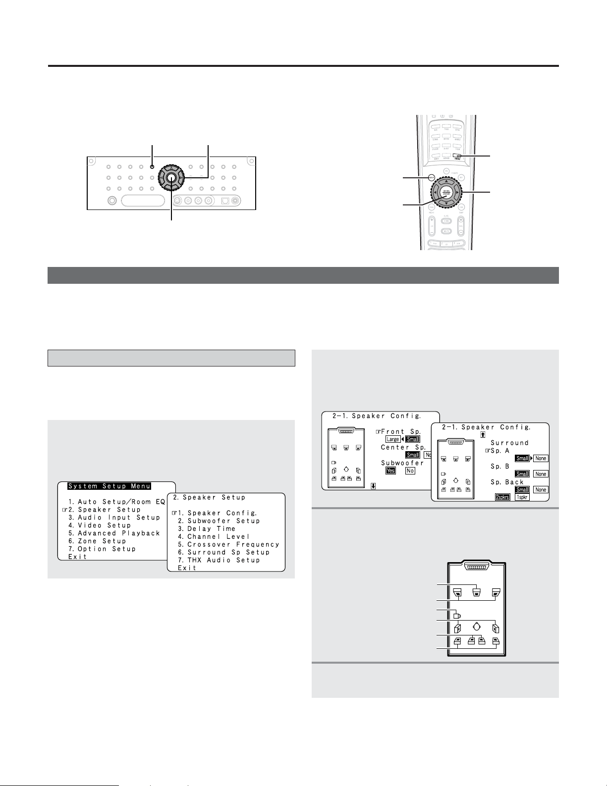
Advanced Setup – Part 2
140
Setting the type of speakers
1
Press the CURSOR
DD
or
HH
button to select
“Speaker Setup” at the “System Setup Menu”,
then press the
ENTER button.
• The “Speaker Setup” menu appears.
• The composition of the signals output to each channels and
the frequency response are adjusted according to the
combination of speakers actually being used.
4
Press the ENTER button to enter the setting.
• The “Speaker Setup” menu reappears.
3
Press the CURSOR
DD
or
HH
button to select the
speaker, then press the
CURSOR
FF
or
GG
button
to select the parameter.
Center Sp.
Front Sp.
Subwoofer
Surround Sp. A
Surround back Sp.
Surround Sp. B
• This Speaker Setup section describes the procedures to make speaker settings manually (without using the Auto Setup
function), as well as to make manual changes to settings that have already been made by the Auto Setup function.
2
Press the CURSOR
DD
or
HH
button to select
“Speaker Config.”, then press the
ENTER
button.
• The “Speaker Config.” screen appears.
Speaker Setup
• If the “Auto Setup” procedure has already been performed, there is no need to make this setting.
• Perform this setting if you wish to make the settings for your speaker systems manually.
SYSTEM SETUP
ENTER
CURSOR
TEST TONE
SYSTEM SETUP
ENTER
CURSOR
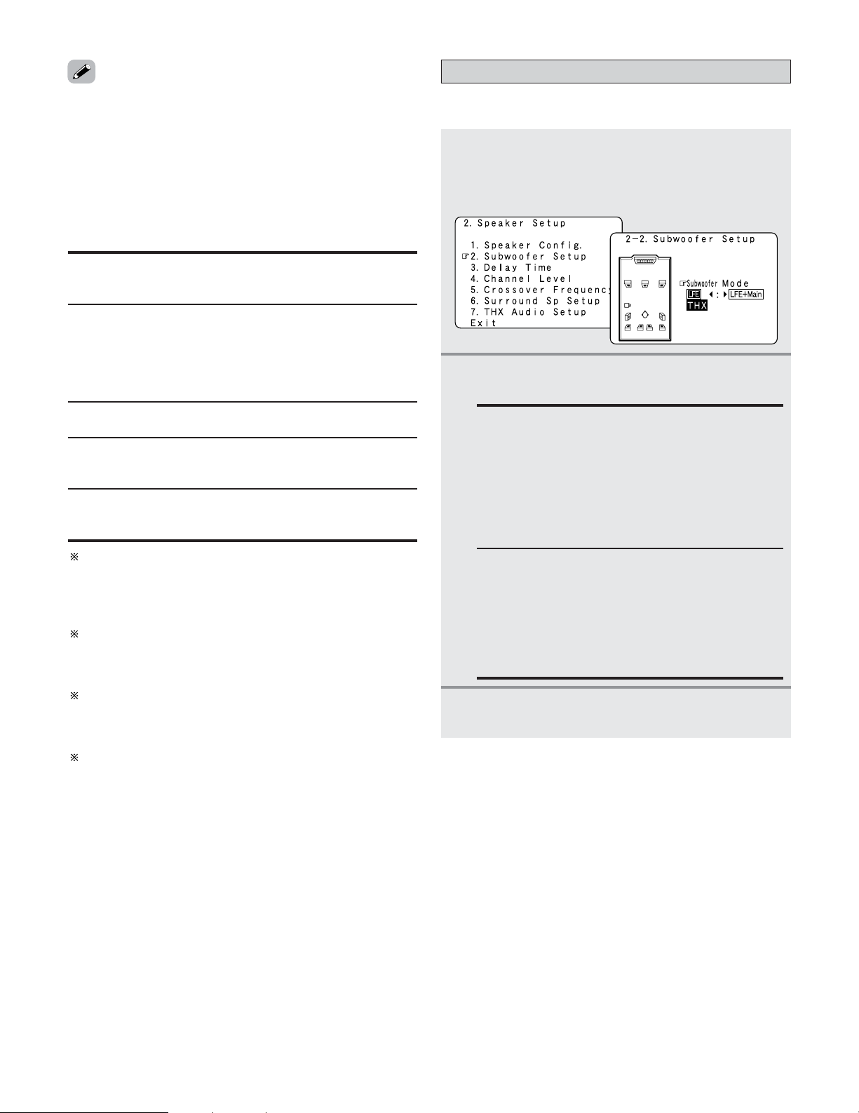
141
Advanced Setup – Part 2
2 Parameters
Large:
Select this when using speakers that can fully reproduce
deep bass well below 80 Hz.
Yes / No:
Select “Yes” when a subwoofer is installed, “No” when a
subwoofer is not installed.
Small:
Select this when using speakers that are not capable of
handling deep bass well below 80 Hz. Most home theater
main and surround speakers perform best when configured
as SMALL. Deep bass content in any channel with a
SMALL speaker is routed to the subwoofer(s).
None:
Select this when no speakers are installed.
2spkrs / 1spkr:
Select the number of speakers to be used for the surround
back channel.
A subwoofer with sufficient low frequency playback
capability can better handle deep bass than most main and
surround speakers, and the system’s overall performance
will be greatly enhanced when SMALL is set for the main
(front) and surround speakers.
To take full advantage of the performance of the Home THX
certified speaker systems, set the front, center and
surround speaker size parameters to “Small” and the
subwoofer to “Yes”.
For the majority of speaker system configurations, using
the SMALL setting for all main and surround speakers and
connected subwoofer(s) set to ON will yield the best
results.
When “Front” is set to “Small”, “Subwoofer” is
automatically set to “Yes”, and when “Subwoofer” is set
to “No”, “Front” is automatically set to “Large”.
Setting the low frequency distribution
1
Press the CURSOR
DD
or
HH
button to select
“Subwoofer Setup” at the “Speaker Setup”
menu, then press the
ENTER button.
• The “Subwoofer Setup” screen appears.
• This selects the subwoofer for playing deep bass signals.
3
Press the ENTER button to enter the setting.
• The “Speaker Setup” menu reappears.
2
Press the CURSOR
FF
or
GG
button to select the
setting.
LFE–THX–:
For any channel(s) that are set to LARGE, low
frequencies in that channel’s corresponding source
are directed to that loudspeaker only. Low
frequencies that are directed to the subwoofer(s)
are from the program source LFE channel, and
from other channels where the speakers are set to
SMALL. THX recommends this mode so that bass
interference is less likely to occur in the room.
LFE+Main:
Low frequencies from speaker channels that have
been set to LARGE are reproduced from those
speakers as well as from the subwoofer(s).
Depending upon the characteristics of the LARGE
main speakers, this mode may provide a more even
low frequency response throughout the listening
room.
• Select “Large” or “Small” not according to the actual size of
the speaker but according to the speaker’s capacity for
playing low frequency (bass sound below the frequency set
for the Crossover Frequency) signals. If you do not know, try
comparing the sound at both settings (setting the volume to
a level low enough so as not to damage the speakers) to
determine the proper setting.
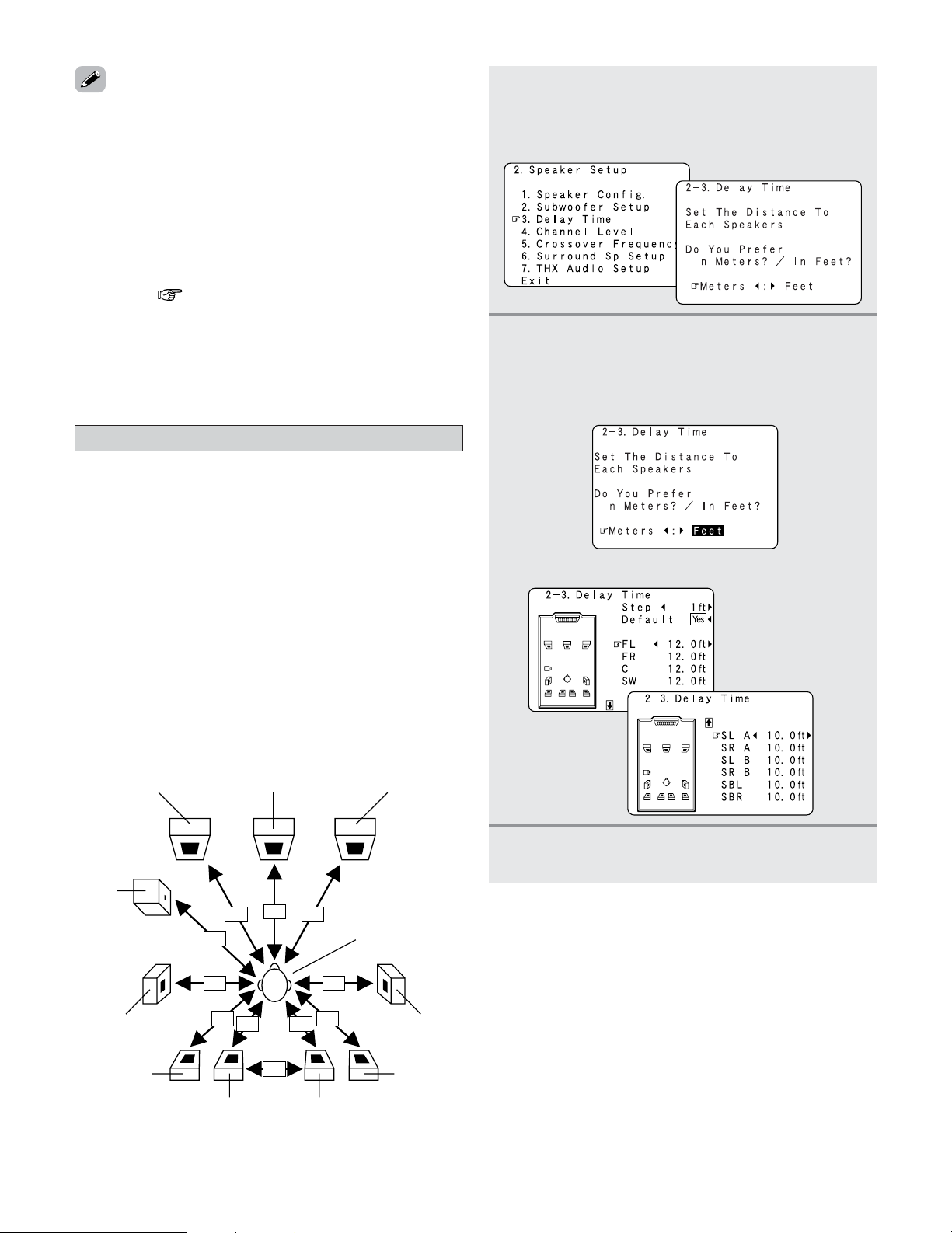
142
Advanced Setup – Part 2
Setting the Delay Time
1
Press the CURSOR
DD
or
HH
button to select
“Delay Time” at the “Speaker Setup” menu,
then press the
ENTER button.
• The “Delay Time” screen appears.
• This parameter is for optimizing the timing with which the
audio signals are produced from the speakers and
subwoofer according to the listening position.
•Two surround back speakers are required to use the THX
Ultra2 Cinema, THX Music mode and THX Games mode.
Set the surround back speakers so that the distance to the
listening position is the same for both the left and right
speakers.
It is also recommended that the deviations of the distance
from the listening position to L and R channel speakers (front
left (FL) and front right (FR), surround left (SL) and surround
right (SR), surround back left (SBL) and surround back right
(SBR)) is less than 2 ft (60 cm).
Preparations:
Measure the distances between the listening position and
the speakers (L1 to L11 on the diagram at the below).
L1 L2
L3
L4
L5
L6
L7 L8
L9 L10
L11
CFRFL
SW
Listening position
SLA
2
Press the CURSOR
FF
or
GG
button to select the
desired unit, “Meters” or “Feet”.
• The “Delay Time” screen appears automatically.
Example: When “Feet” is selected
3
Press the CURSOR
DD
or
HH
button to select the
speaker to be set.
2 Assignment of low frequency signal range
• The only signals produced from the subwoofer channel are
LFE signals (during playback of Dolby Digital or DTS signals)
and the low frequency signal range of channels set to
“Small” in the setup menu. The low frequency signal range
of channels set to “Large” are produced from those
channels.
2
Subwoofer Setup
• The subwoofer mode setting is only valid when and “Yes”
is set for the subwoofer in the “Speaker Configuration”
settings ( page 140, 141).
• When the input signal is analog or a PCM signal not
including LFE signals, if “LFE–THX–” is selected, the low
frequency component is not output from the subwoofer. To
output the subwoofer channel, select “LFE+Main”.
SRA
SLB
SRB
SBL SBR
......... L1
......... L2
......... L3
......... L4
......... L5
......... L6
......... L7
......... L8
......... L9
....... L10
hh
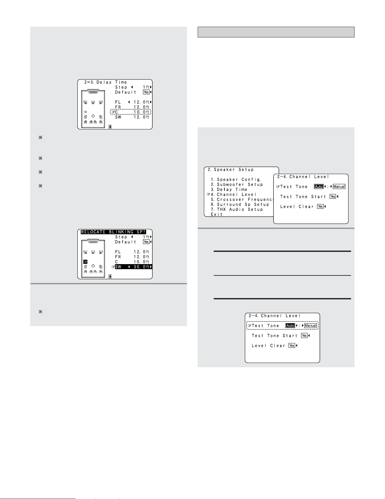
143
Advanced Setup – Part 2
4
Press the CURSOR
FF
or
GG
button to set the
distance between the center speaker and
listening position.
Example: When the distance is set to 10.0 feet for the
center speaker
The distance changes in units of 1 foot or 0.1 foot each
time the button is pressed. Select the value closest to
the measured distance.
When “Step” is selected, you can select the unit of “1
ft (0.1 m)” or “0.1 ft (0.01 m)”.
When “Default Yes” is selected, then press the
CURSOR
FF
button to reset to the default values.
The difference of the distances set for the various
speakers must be 20.0 ft (6.0 m) or under. If an
inappropriate distance is set, “RELOCATE
BLINKING SP!” is displayed. In this case, move the
relevant speaker to the proper position as
indicated by the displayed value.
5
Press the ENTER button to enter the setting.
• The “Speaker Setup” menu reappears.
The AVR-5805CI automatically sets the optimum
surround delay time for the listening room.
Setting the Channel Level
• Use this setting to adjust so that the playback level between
the different channels is equal.
•From the listening position, listen to the test tones produced
from the speakers to adjust the level.
• The level of each channel should be adjusted to 75 dB (C-
weighted, slow meter mode) on a sound level meter at the
listening position.
If a sound level meter is not available adjust the channels by
ear so the sound levels are the same. Because adjusting the
subwoofer level test tone by ear is difficult, use a well
known music selection and adjust for natural balance.
1
Press the CURSOR
DD
or
HH
button to select
“Channel Level” at the “Speaker Setup”
menu, then press the
ENTER button.
• The “Channel Level” screen appears.
2
Press the CURSOR
FF
or
GG
button to select
“Auto” or “Manual”.
Auto:
Adjust the level while listening to the test tones
produced automatically from each speaker.
Example: When the “Auto” mode is selected
Manual:
Select the speaker from which you want to
produce the test tone to adjust the level.
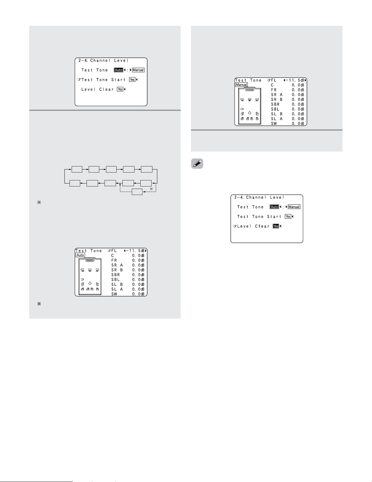
144
Advanced Setup – Part 2
3
Press the CURSOR
DD
or
HH
button to select
“Test Tone Start”, then press the
CURSOR
FF
button to select “Yes”.
4
-1
When “Auto” mode is selected:
Press the
CURSOR
FF
or
GG
button to adjust all
the speakers to the same volume.
• The test tones are emitted from each speaker in the
following order, at 4 seconds intervals the first time
and second time around, 2 seconds intervals the
third time around and on:
The volume can be adjusted between –12.0 dB and
+12.0 dB in units of 0.5 dB.
4
-2
When “Manual” mode is selected:
Press the
CURSOR
DD
or
HH
button to select the
speaker, then press the
CURSOR
FF
or
GG
button
to adjust all the speakers to the same volume.
Example: “Manual” mode is selected.
5
Press the ENTER button to enter the setting.
• The “Channel Level” screen reappears.
FL
SW
1spkr
2spkrs
C
FR
SRA
SBL
SLB
SLA
SB
SRB
SBR
When the surround back speaker setting is set to
“1spkr” for “Speaker Configuration”, this is set to
“SB”.
Example: When the volume is set to –11.5 dB while
the test tone is being produced from the
Front L ch speaker
•To cancel the settings, press the CURSOR
FF
button to select
“Level Clear” and “Yes” on the “Channel Level” screen,
then make the settings again.
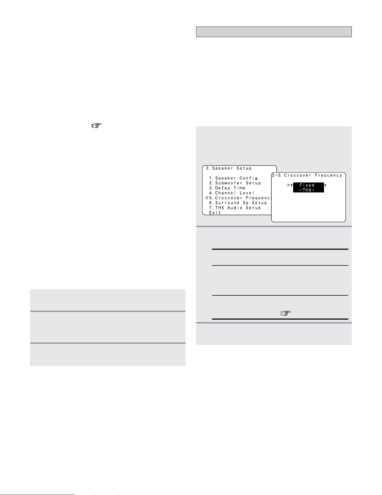
145
Advanced Setup – Part 2
• When adjusting the level of an active subwoofer system,
you may also need to adjust the subwoofer’s own volume
control.
• When you adjust the channel levels while in the SYSTEM
SETUP CHANNEL LEVEL mode, the channel level
adjustments made will affect all surround modes. Consider
this mode a Master Channel Level adjustment mode.
• After you have completed the SYSTEM SETUP CHANNEL
LEVEL adjustments, you can then activate the individual
surround modes and adjust channel levels that will be
remembered for each of those modes. Then, whenever you
activate a particular surround sound mode, your preferred
channel level adjustments for just that mode will be recalled.
Check the instructions for adjusting channel levels within
each surround mode ( page 63, 64).
•You can adjust the channel levels for each of the following
surround modes: PURE DIRECT/DIRECT, STEREO,
STANDARD (DOLBY/DTS SURROUND), HOME THX
CINEMA, 9CH STEREO, WIDE SCREEN, SUPER STADIUM,
ROCK ARENA, JAZZ CLUB, CLASSIC CONCERT, MONO
MOVIE, VIDEO GAME and MATRIX.
• When using either surround speakers A or B, or when using
surround speakers A and B at the same time, be sure to
adjust the balance of playback levels between each channel
for the various selections of “A”, “B” and “A + B”.
Setting the Crossover Frequency
• Set the crossover frequency according to the low frequency
response characteristics of the various (front, center,
surround and surround back) speaker systems.
• If a connected main or surround loudspeaker has a specified
–3 dB low frequency response rolloff, adjust the crossover
frequency for that speaker to match the specified low
frequency response limit – e.g. 80 Hz.
• When a speaker is set to SMALL, low frequencies in that
channel that are below the crossover frequency are directed
to the system’s subwoofer(s), or to speakers that are set to
LARGE, for systems with no connected subwoofer(s).
1
Press the CURSOR
DD
or
HH
button to select
“Crossover Frequency” at the “Speaker
Setup” menu, then press the
ENTER button.
•The “Crossover Frequency” screen appears.
2
Press the CURSOR
FF
or
GG
button to select the
frequency.
FIXED–THX–:
Set to the THX rated 80 Hz crossover frequency.
VARIABLE 40, 60, 80, 90, 100, 110, 120, 150, 200, 250
Hz:
Set as desired according to your speakers’ bass
playback ability.
Advanced
The crossover frequency can be set individually for
the different speakers ( page 146).
3
Press the ENTER button to enter the setting.
• The “Speaker Setup” menu reappears.
1
Press the TEST TONE button.
•Test tones are output from the different speakers.
2
Press the CURSOR
FF
or
GG
button to adjust the
channel level so that the volume of the test
tones is the same for all the speakers.
3
After completing the adjustment, press the
TEST TONE button again.
2 Adjusting the test tone using the remote control
unit
• As described below, this adjustment can be accomplished
via the with remote control unit.
• Adjusting with the remote control unit using the test tones
is only possible in the “Auto” mode and only effective in
the STANDARD (DOLBY/DTS SURROUND) and HOME
THX CINEMA modes. The adjusted levels for the different
modes are automatically stored in the memory.
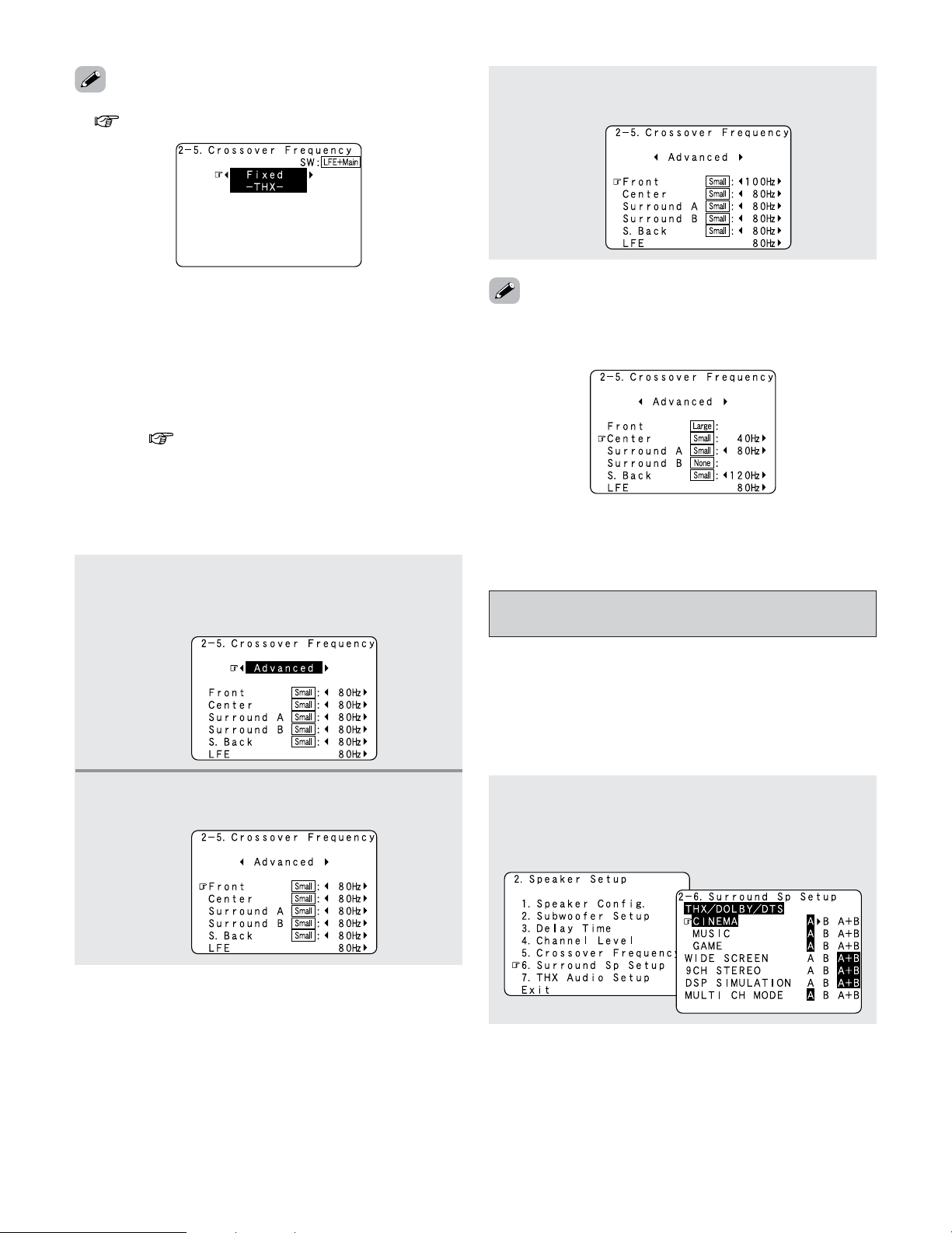
146
Advanced Setup – Part 2
• Please set all THX Certified speakers to small and the
crossover to 80 Hz.
•We recommend using with the crossover frequency set to
“FIXED–THX–”, but depending on the speaker, setting it to a
different frequency may improve frequency response near
the crossover frequency.
• The crossover frequency mode is valid only when subwoofer
is set to “Yes”, and when one or more speakers are set to
SMALL, as described in section “Speaker Configuration”
settings ( page 140, 141).
1
Press the CURSOR
FF
or
GG
button to select
“Advanced” at the “Crossover Frequency”
screen.
2
Press the CURSOR
DD
or
HH
button to select the
speaker to be set.
• If “LFE–THX–” is selected at “Subwoofer Setup”, the
frequencies can only be selected for speakers set to “Small”
at “Speaker Configuration”.
• If “LFE+Main” is set at “Subwoofer Setup”, the frequencies
can be selected regardless of the speaker size setting.
Selecting the Surround Speakers for the
different surround modes
• Use this function when using multiple surround speaker
combinations for more ideal surround sound.
• Once the combinations of surround speakers to be used for
the different surround modes are preset, the surround
speakers are selected automatically according to the
surround mode.
1
Press the CURSOR
DD
or
HH
button to select
“Surround Sp Setup” at the “Speaker Setup”
menu, then press the
ENTER button.
• The “Surround Sp Setup” screen appears.
• If “LFE+Main” is set at “Subwoofer Setup”, “SW:LFE+Main”
( page 141, 142) is displayed at the top right of the screen.
3
Press the CURSOR
FF
or
GG
button to select the
frequency.
2
Setting the crossover frequency individually for
the different channels
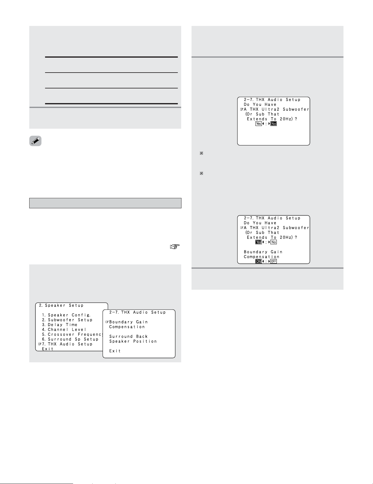
147
Advanced Setup – Part 2
• For the “WIDE SCREEN” and “9CH STEREO” DSP
simulation modes, the surround speakers can be set
separately.
• See page 105 for the selection of the surround speakers
when the “ANALOG” mode is selected at “EXT. IN Setup”.
Settings the THX Audio Setup
1
Press the CURSOR
DD
or
HH
button to select
“THX Audio Setup” at the “Speaker Setup”
menu, then press the
ENTER button.
• The “THX Audio Setup” screen appears.
When “Yes” is selected:
“Boundary Gain Compensation” can be selected and
the compensation set to “OFF”.
If the bass sound seems too strong:
Set “Boundary Gain Compensation” to “ON”. This
activates a filter that gently reduces very deep bass
below 55 Hz to provide the flattest overall deep bass
response. Select “ON” or “OFF” according to how
strong you prefer the deep bass response to be.
4
Press the ENTER button.
• The “THX Audio Setup” screen reappears.
2
Press the CURSOR
DD
or
HH
button to select
“Boundary Gain Compensation”, then press
the
ENTER button.
3
Press the CURSOR
FF
or
GG
button, when using
a THX Ultra2 compatible subwoofer or
subwoofer that frequency response extends to
20 Hz, select “Yes”. Otherwise select “No”.
2
Press the CURSOR
DD
or
HH
button to select the
surround mode, then press the
CURSOR
FF
or
GG
button to select the surround speaker.
A:
When surround speakers A is used.
B:
When surround speakers B is used.
A + B:
When both surround speakers A and B are used.
3
Press the ENTER button to enter the setting.
• The “Speaker Setup” menu reappears.
2
Settings for using a THX Ultra2 compatible
subwoofer
• Make these settings when “Yes” is selected for the
subwoofer in the “Speaker Configuration” settings.
This option is not available when “No” is selected (
page 140, 141).
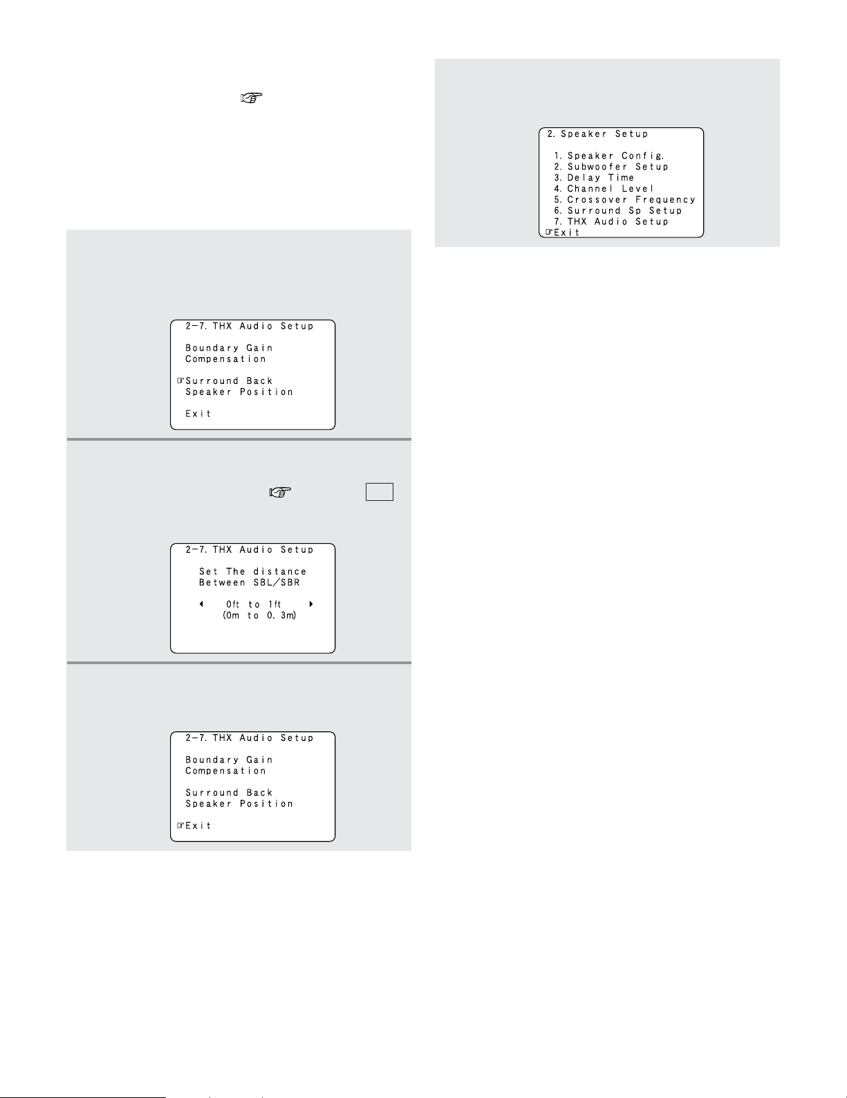
148
Advanced Setup – Part 2
1
Press the CURSOR
DD
or
HH
button to select
“Surround Back Speaker Position” at the
“THX Audio Setup” screen, then press the
ENTER button.
2
Press the CURSOR
FF
or
GG
button to select the
settings according to the distances of the two
surround back speakers ( page 142 : ),
then press the
ENTER button.
• The “THX Audio Setup” screen reappears.
L11
3
Press the CURSOR
DD
or
HH
button to select
“Exit”, then press the
ENTER button.
• The “Speaker Setup” menu reappears.
4
Press the CURSOR
DD
or
HH
button to select the
“Exit”, then press the
ENTER button.
• The “System Setup Menu” reappears.
2
Surround Back Speaker Position Settings
•When two surround back speakers have been set in
“Speaker Configuration” ( page 140, 141), set the
distance of the speakers. This option is not available when
“1spkr” is selected.
• This setting is necessary to achieve the optimum effect in
the THX Surround EX, THX Ultra2 Cinema, THX Music
mode and THX Games mode. It is recommended that
SBL/SBR speakers are placed together as close as
possible.
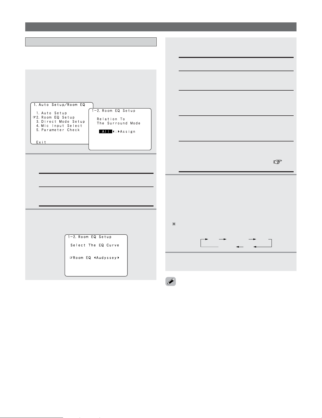
149
Advanced Setup – Part 2
Setting the Room EQ Setup
1
Press the CURSOR
DD
or
HH
button to select
“Room EQ Setup” at the “Auto Setup / Room
EQ” menu, then press the
ENTER button.
• The “Room EQ Setup” screen appears.
• Set the Room EQ setting with All or Assign for each
surround mode.
All:
Sets the Equalizer for all surround modes.
Assign:
Sets the Equalizer individually for each surround
mode.
2
Press the CURSOR
FF
or
GG
button to select
“All” or “Assign”.
3
-1
When “All” is selected:
q Press the
ENTER button.
• The “Select the EQ Curve” screen appears.
3
-2
When “Assign” is selected:
After completing system setup, select the
desired equalizer setting pressing the
ROOM
EQ
button.
• Equalizer settings for the individual surround modes
can be stored in the memory.
Whenever the ROOM EQ button is pressed, the display
switches as shown below.
Flat:
Adjusts the frequency response of all speakers to
the flattest response. This mode is suitable for
multi-channel music surround sound sources.
Manual:
Selects the setting value that was set in the Manual
EQ Setup.
For details of the “Manual EQ Setup” ( page
118, 119).
OFF Audyssey
FlatManual
Front
Front:
Adjusts the frequency response of the surround
speakers to match the characteristics of the front
channel speakers.
4
Press the ENTER button to enter the setting.
• The “Auto Setup / Room EQ” menu reappears.
Others Setup
• The Equalizer setting of “Audyssey”, “Front” and “Flat” can
be selected after performing the Auto Setup.
• When the speaker set as “None” with the Auto Setup is
changed to on manually, the equalizer of “Audyssey”,
“Front” and “Flat” cannot be used.
• The Equalizer setting can be selected directly by ROOM EQ
button.
• When headphones are connected, the Room EQ cannot be
used.
w Press the CURSOR
FF
or
GG
button to select
the equalizer setting.
OFF:
The Equalizer is not used.
Audyssey:
Adjusts the frequency response of all speakers to
correct the effects of room acoustics.
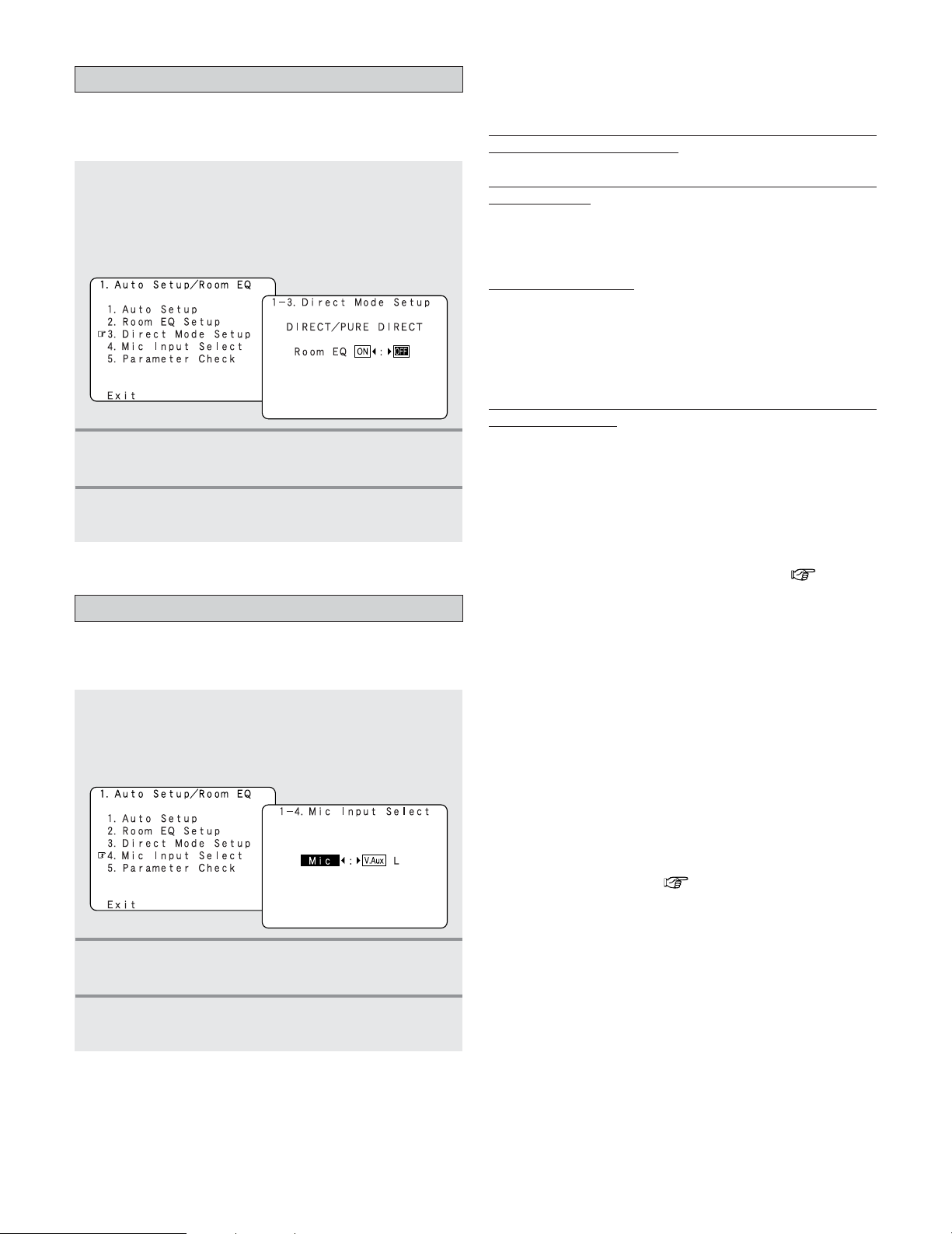
150
Advanced Setup – Part 2
Setting the Direct Mode Setup
1
Press the CURSOR
DD
or
HH
button to select
“Direct Mode Setup” at the “Auto Setup /
Room EQ” menu, then press the
ENTER
button.
• The “Direct Mode Setup” screen appears.
• Set the ON/OFF setting of Room EQ, in the case of the
surround mode is in DIRECT or PURE DIRECT.
2
Press the CURSOR
FF
or
GG
button to select
“ON” or “OFF”.
3
Press the ENTER button to enter the setting.
• The “Auto Setup / Room EQ” menu reappears.
Setting the MIC Input Select
1
Press the CURSOR
DD
or
HH
button to select
“Mic Input Select” at the “Auto Setup / Room
EQ” menu, then press the
ENTER button.
• The “Mic Input Select” screen appears.
• Set this to switch the Mic Input jack for use for Mic jack or
V.AUX L-channel input terminal.
2
Press the CURSOR
FF
or
GG
button to select
“Mic” or “V.AUX L”.
3
Press the ENTER button to enter the setting.
• The “Auto Setup / Room EQ” menu reappears.
Required Microphone for DENON Auto-Setup Room EQ :
Product name Countryman B3
Required Microphone Amplifier Specification for DENON Auto-
Setup Room EQ
• Gain : 29 dB
•Frequency Response : 10 ~ 30 kHz Full Flat
(Ex : Rane MS1b)
Micr
ophone Placement
• Set the microphone using microphone stand, or other
method, at the prime listening position.
• Point the top of the microphone toward the ceiling.
• Adjust the height so that the top of microphone to matches
the height of your ear when sitting.
Micr
ophone Amplifier Gain Setting using Sound Level Meter
and RMS Volt Meter
First you will need to adjust the “ microphone amplifier gain”.
(1) Connect the all speakers and the video monitor (for the
on screen display) with the AVR-5805CI.
(2) Connect the microphone with the microphone amplifier.
(3) Turn on the AVR-5805CI and the “microphone amplifier”.
(4) Turn on the “Phantom Supply” on the microphone
amplifier.
(5) Set the Parameter “Test Tone” to “Manual” and “Test
Tone Start” to “Yes” at “Channel Level” ( page 143
~ 145).
(6) Once the test tone for Front Left (FL) speaker starts,
check the Sound Pressure Level at the Listening
Position with an SPL Meter. You do not have to check
any of the other channels.
(7) Adjust the “Main Volume” so that the Sound Pressure
Level measures 80 dB (C-weighted).
(8) Once the “Main Volume” as been set, connect the
output of microphone amplifier to the RMS Volt Meter.
(9) Adjust the “microphone amplifier’s gain” as the RMS
Volt Meter becomes about 120 [mV RMS].
(10) Once set, exit out of “System Setup” and turn off the
AVR-5805CI.
(11) Connect the output of the microphone amplifier to the
AVR-5805CI’s front panel “V.AUX” Left channel audio
input–located behind Trap Door.
(12) Change the setting to “V.AUX L” at “Mic Input Select”.
(13) Start “Auto Setup” ( page 20 ~ 26).
2 Specifications and Setup Procedure for Non-
DENON Microphone
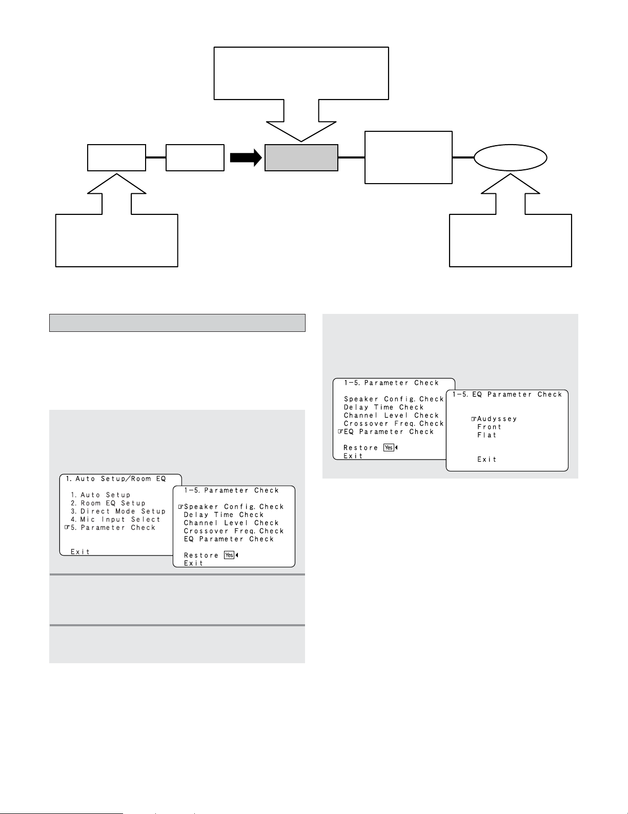
151
Advanced Setup – Part 2
Check the parameter
1
Press the CURSOR
DD
or
HH
button to select
“Parameter Check” at the “Auto Setup / Room
EQ” menu, then press the
ENTER button.
• The “Parameter Check” screen appears.
• The results of the measured items can be checked.
• The EQ parameters that were set in Auto Setup can be
checked.
• This item is displayed, after the measurement result of the
“Auto Setup / Room EQ” is decided.
2
Press the CURSOR
DD
or
HH
button to select the
items, then press the
ENTER button.
• The verification screen appears.
4
Press the CURSOR
DD
or
HH
button to select “EQ
Parameter Check”, then press the
ENTER
button.
• The “EQ Parameter Check” screen appears.
AVR-5805CI
Speaker Microphone
Use the internal test tones
for mic amp calibration.
Pressure level with SPL meter at the
microphone point.
Adjust AVR volume SPL meter = 80 dB (C)
MIC AMP with mic
power supply ex.
mixer amp.
Measure the output level
and adjust the mic amp gain
to 120 mVrms using a RMS
volt meter.
120 mVrms
3
If the check ends, press the ENTER button
again.
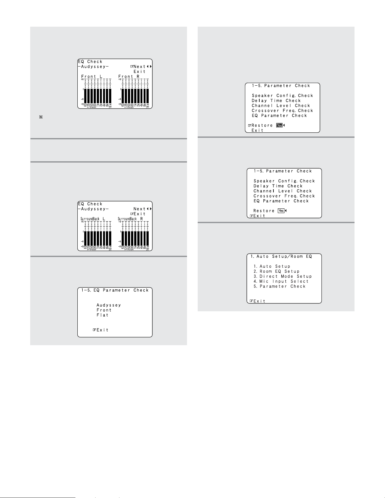
152
Advanced Setup – Part 2
10
Press the CURSOR
DD
or
HH
button to select
“Exit”, then press the
ENTER button.
• The “Auto Setup / Room EQ” menu reappears.
11
Press the CURSOR
DD
or
HH
button to select
“Exit”, then press the
ENTER button.
• The “System Setup Menu” reappears.
5
Press the CURSOR
DD
or
HH
button to select the
Equalizer curve, then press the
ENTER button.
• The “EQ Check” screen appears.
The display is only an approximate picture of the
response and that correction is happening at all
frequencies.
6
Press the CURSOR
FF
or
GG
button to select the
speaker channel.
7
If the check ends, press the CURSOR
DD
or
HH
button to select “Exit”, then press the
ENTER
button.
• The “EQ Parameter Check” screen reappears.
8
Press the CURSOR
DD
or
HH
button to select
“Exit”, then press the
ENTER button.
• The “Parameter Check” screen reappears.
The results of the “Auto Setup” procedure can
be reset even if the settings have been changed
after performing the “Auto Setup” procedure:
Press the
CURSOR
DD
or
HH
button to select
“Restore Yes
0
”, then press the CURSOR
FF
button.
9
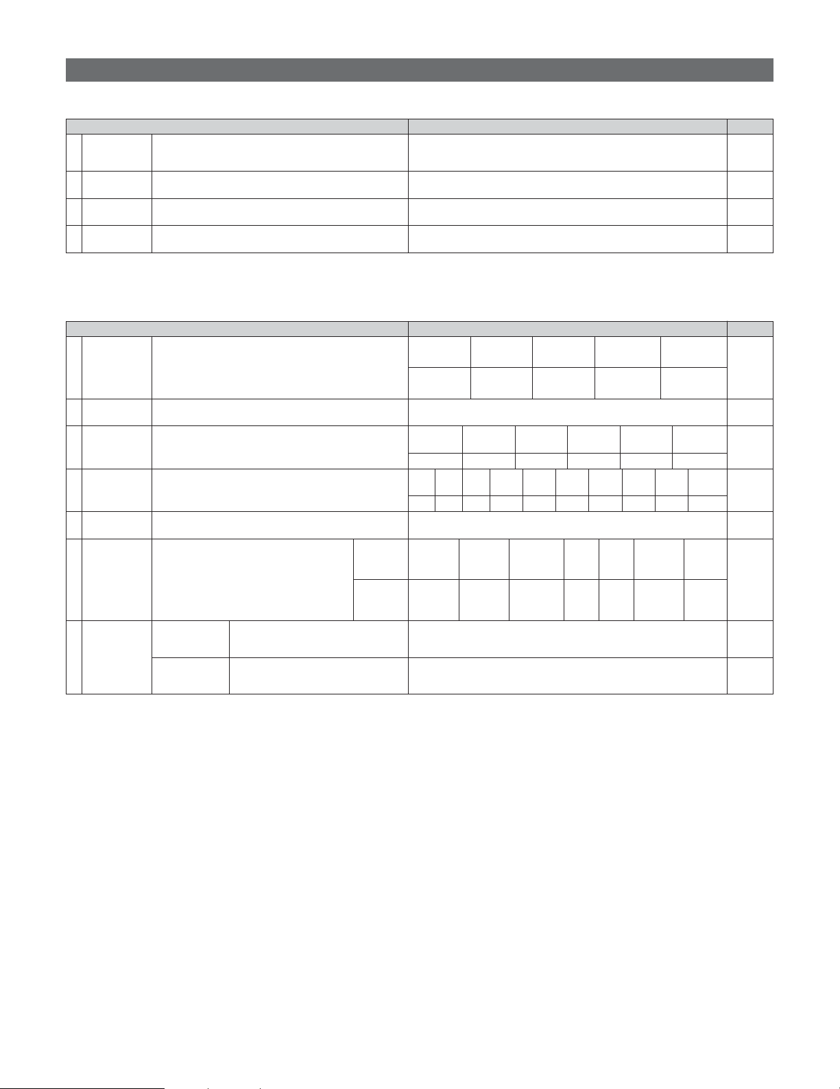
153
Advanced Setup – Part 2
PageDefault settingsSpeaker Setup
PageDefault settingsAuto Setup / Room EQ
1. Auto Setup/Room EQ
1 Auto Setup
Room EQ
Setup
2
Direct Mode
Setup
4
Set the ON/OFF setting of Room EQ, in the case of the
surround mode is in Direct or Pure Direct.
3
Mic Input
Select
Set this to switch the Mic Input jack for use for Mic or
V.AUX L-channel input jack.
This unit performs an analysis of the speaker system and
measures the acoustic characteristics of your room to
permit an appropriate automatic setting.
Set the Room EQ setting with All or Assign for each
surround mode.
–
All, Room EQ = OFF
OFF
Mic
20 ~ 26
149
150
150, 151
System setup items and default values (set upon shipment from the factory)
2. Speaker Setup
1
3
Speaker
Configuration
Channel
Level
Input the combination of speakers in your system and their
corresponding sizes (SMALL for regular speakers, LARGE
for full-size, full-range) to automatically set the composition
of the signals output from the speakers and the frequency
response.
This adjusts the volume of the signals output from the
speakers and subwoofer for the different channels in order
to obtain optimum effects.
Front Sp.
Small
Center Sp.
Surround Sp.
A / B
Subwoofer
Small SmallYes
Front L & R Center
Surround
L & R (A)
Subwoofer
12.0 ft (3.6 m) 12.0 ft (3.6 m) 10.0 ft (3.0 m)12.0 ft (3.6 m)
Front L Front R Center
Surround
R (A)
Surround
Back L
Surround
Back R
Subwoofer
0 dB 0 dB 0 dB 0 dB 0 dB 0 dB 0 dB
Surround Back Sp.
Small / 2spkrs
4
Delay Time
This parameter is for optimizing the timing with which the
audio signals are produced from the speakers and
subwoofer according to the listening position.
Surround
L & R (B)
10.0 ft (3.0 m)
Surround
L (A)
0 dB
Crossover
Frequency
Set the frequency (Hz) below which the bass sound of the
various speakers is to be output from the subwoofer.
5
FIXED —THX—
140, 141
2
Subwoofer
Setup
This selects the subwoofer for playing deep bass signals.
LFE —THX—
141, 142
142, 143
143 ~ 145
145, 146
Surround
Speaker
Setup
Use this function when using multiple
surround speaker combinations for more ideal
surround sound. Once the combinations of
surround speakers to be used for the different
surround modes are preset, the surround
speakers are selected automatically according
to the surround mode.
Surround
mode
Surround
speaker
THX/DOLBY/
DTS CINEMA
THX/DOLBY/
DTS MUSIC
WIDE
SCREEN
9 CH
STEREO
DSP
SIMULATION
MULTI CH
MODE
AA AA+B A+B A+B A
6
THX/
DOLBY GAME
146, 147
7
THX Audio
Setup
When using a THX Ultra2 compatible
subwoofer, set the subwoofer’s
frequency response.
THX Ultra2 Subwoofer = NO
Boundary Gain
Compensation
Surround Back
Speaker
Position
When using two surround back
speakers, set the distance of the two
speakers.
The Distance Between SBL/SBR = 0 ft to 1 ft (0 m to 0.3 m)
147
Surround
Back
10.0 ft (3.0 m)
Surround
R (B)
0 dB
Surround
L (B)
0 dB
148
154
Advanced Setup – Part 2
Video Setup PageDefault settings
Audio Input Setup PageDefault settings
3. Audio Input Setup
104
Digital In
Assignment
CD DVD VDP TV DBS VCR-1 VCR-2
COAX
1
COAX
2
COAX
3
COAX
4
COAX
5
OPT 1 OPT 2
This assigns the digital input terminals for the
different input sources.
Input
source
Digital
Inputs
1
CDR /
TAPE
OPT 4
VCR-3 VCR-4
OPT 3
V. AUX
OPT 5 OPT 6
2 EXT.IN Setup Set the EXT.IN terminal playback method.
Mode = DSP, Surr.B = NOT USED, S.Back = NOT USED,
SW Level = +15 dB, Input ATT. = OFF
Mode = DSP, SW Level = +15 dB, Input ATT. = OFF
106
Input
Function
Level
The playback level is corrected individually for the different
input sources.
TUNER PHONO CD
CDR /
TAPE
DVD VDP TV
0 dB 0 dB 0 dB 0 dB 0 dB 0 dB 0 dB
3
VCR-2
0 dB
DBS VCR-1
0 dB 0 dB
VCR-3 VCR-4
0 dB
V.AUX
0 dB
4
Function
Rename
The names of the different input function can be changed
as desired and displayed on the display.
106, 107
5
IEEE1394
Assignment
The connected IEEE1394 device can be automatically
identified to assign the input source.
–
107
6
IEEE1394
Auto
Function
Set the function for associating playback of the connected
IEEE1394 device on or off.
Auto Function = OFF
108
7
Tuner
Presets
FM stations are received automatically and
stored in the memory.
A1 ~ A8
B1 ~ B8
C1 ~ C8
D1 ~ D8
E1 ~ E8
87.5/89.1/98.1/107.9/90.1/90.1/90.1/90.1 MHz
520/600/1000/1400/1500/1710 kHz, 90.1/90.1 MHz
90.1 MHz
90.1 MHz
90.1 MHz
Auto
Preset
Memory
F1 ~ F8
G1 ~ G8
90.1 MHz
90.1 MHz
Preset channels that are not used often can be
skipped.
Preset
Skip
The preset channels can be given the names
you want.
Preset
Name
108
All preset channels = ON
109
–
109
105
TUNER PHONO CD
CDR /
TAPE
DVD VDP TV VCR-2DBS VCR-1 VCR-3 V.AUX
4. Video Setup
2
Component In
Assignment
HDMI/DVI In
Assignment
This assigns the color difference (component) video input
terminals for the different input sources.
The HDMI or DVI-D input terminals are assigned for the
different input sources.
Select HDMI or DVI-D for the monitor output terminal.
Select the HDMI audio signal playback method.
DVD VDP TV
1
112
3
Video Convert
Mode
This sets whether or not to use the video conversion
function.
ON
112
111, 112
DBS VCR-1 VCR-2 VCR-3 V.AUX
1-RCA 2-RCA 3-RCA 4-RCA 5-RCA 6-BNC NONE NONE
Audio Delay
Set the audio delay timing to synchronize the sound and
video.
5
0 ms
114
On Screen
Display
This sets whether or not to display the on screen display
that appears on the monitor screen when the controls on
the remote control unit or main unit are operated.
6
Function/Mode = ON, Master Volume = ON, iRadio/mServer = Always, XM = Always,
Screensaver = ON, Display Mode = Mode 1
115
DVD VDP TV DBS VCR-1 VCR-2 VCR-3 VCR-4 V.AUX
NONE NONE NONE NONE NONE NONE NONE NONE
4
HDMI/
Component
Out
Set the format of the signal up-converted to the HDMI
monitor output or component video output terminal.
Convert = ON, Scaler = HDMI, Aspect = Full, Resolution = 480p/576p
Color Space = Y Cb Cr, RGB Mode = Normal
113, 114
Aux
0 dB
Net
Audio
EXT.IN-1
Setup
EXT.IN-2
Setup
0 dB
VCR-4
NONE
VCR-4
NONE
PageDefault settingsZone Setup
155
Advanced Setup – Part 2
6. Zone Setup
1
2
Speaker
Configuration
This selects the subwoofer used in ZONE2 for playing the
low base sound.
6
Subwoofer
Mode
Set the presence/absence of speaker combinations and
the size in function of the low frequency reproduction
capabilities when playing surround sound in ZONE2.
LFE
ON
120
120
123, 124
This sets whether or not to use the video
conversion function.
Video
Convert
Mode
Set the delay time the sound is synchronized
with the picture which are output in ZONE2.
Audio
Delay
Video Setup
0 ms
7
Bass = 0 dB, Treble = 0 dB, HPF = OFF, L/R = 0 dB
124, 125
Zone3/4
Tone/
Ch.Level
Bass = 0 dB, Treble = 0 dB, HPF = OFF, L/R = 0 dB
Front Sp.
Small
Center Sp. Surround Sp.Subwoofer
Small SmallYes
3
This parameter is for optimizing the timing of the sound
produced from the various speakers and subwoofer
according to the listening position in ZONE2.
Delay Time
121
Front L & R Center Surround L & RSubwoofer
12.0 ft (3.6 m)
12.0 ft (3.6 m)
10.0 ft (3.0 m)
12.0 ft (3.6 m)
4
This adjusts the volume of the signal output from the
various speakers and subwoofer used in ZONE2.
Channel
Level
122, 123
Front L Front R Surround LCenter
0.0 dB 0.0 dB 0.0 dB0.0 dB
Surround R
0.0 dB
Subwoofer
0.0 dB
5
Set the frequency (in Hz) below which deep bass
appearing in the main channels will be routed to the
ZONE2 subwoofer.
Crossover
Frequency
80 Hz
123
Adjust the tone and channel level of the sound
output from ZONE3 and ZONE4.
Zone3
Zone4
PageDefault settingsAdvanced Playback
5. Advanced Playback
1
2
2ch
Direct/Stereo
Auto
Surround
Mode
Turn the audio compression on or off when down-mixing
Dolby Digital signals.
3
Dolby Digital
Setup
The speaker settings can be changed specifically for
playing in the 2 channel direct or stereo mode.
Set the Auto surround mode function.
Basic
OFF
Auto Surround Mode = ON
116
117
117
4
This parameter is for optimizing the Room EQ with which
the audio signals are produced from the speakers.
Manual EQ
Setup
All Channels and Frequency = 0 dB
118, 119
156
Advanced Setup – Part 2
Option Setup PageDefault settings
7. Option Setup
1
Channel
Setup
The number of channels that you wish to play back in each
zone are assigned to each zone accordingly.
Main Zone
Normal
9.1 CH
Zone2 Zone3
5.1 CH Stereo
Zone4
Stereo
126 ~ 128
2
Power Amp
Assignment
Power Amplifiers can be assigned to the various channels
according to your system’s requirements.
129 ~ 133
L1 L2 L3 L4 L5 R1 R2 R3 R4 R5
FL C SLA SLB SBL FR – SRA SRB SBR
AC Outlet
Assignment
This sets the AC outlet to on or off for the
different input sources.
136
139
139
3
Trigger Out
Setup
This sets the Trigger Out output for the
different input sources.
If “ZONE=MAIN” is selected, settings can be
made for the individual surround modes.
4
Volume
Control
5
135
6
Network
Setup
DHCP = ON
138
139
This sets the volume level of each zone output.
Volume Limit:
This sets the upper limit for the master
volume.
Power On Level:
This sets the volume level upon switching on
the power of each zone.
Mute Level:
This sets the amount of attenuation of the
audio output when each zone is muted.
Volume Level:
This sets whether the output level of ZONE2
to 4 is fixed or variable.
134
Vol.Limit = OFF, P. On Lev. = LAST, Mute Lev. = FULL
Vol.Lev. = VAR, Vol.Limit = OFF, P. On Lev. = LAST, Mute Lev. = FULL
Vol.Lev. = VAR, Vol.Limit = OFF, P. On Lev. = LAST, Mute Lev. = FULL
Trigger
Out 1
ZONE = MAIN, All Surround Modes = ON
The IP address-related settings are made here.
IP
Address
The proxy-related settings can be changed
here.
Proxy
Set whether or not to accept
control from the network in the
standby mode.
Standby
Mode Power
Saving
Select the language of the
computer’s OS.
PC
Language
Network
Option
OFF
eng
ON
Main
Zone2
Zone3
Vol.Lev. = VAR, Vol.Limit = OFF, P. On Lev. = LAST, Mute Lev. = FULL
Zone4
Setup
Memory/Lock
7
TUNER PHONO CD
CDR /
TAPE
DVD VDP TV
VCR-2DBS VCR-1 VCR-3 VCR-4 V. AUX
OFF OFF OFF OFF ON ON ON ONON ON ON ON ON
Trigger
Out 2
ZONE = 2
Trigger
Out 3
Trigger
Out 4
ZONE = 3
ZONE = 4
Aux
ON
TUNER PHONO CD
CDR /
TAPE
DVD VDP TV
VCR-2DBS VCR-1 VCR-3 VCR-4 V. AUX
ON ON ON ON ON ON ON ONON ON ON ON ON
Aux
ON
TUNER PHONO CD
CDR /
TAPE
DVD VDP TV
VCR-2DBS VCR-1 VCR-3 VCR-4 V. AUX
ON ON ON ON ON ON ON ONON ON ON ON ON
TUNER PHONO CD
CDR /
TAPE
DVD VDP TV
VCR-2DBS VCR-1 VCR-3 VCR-4 V. AUX
ON ON ON ON ON ON ON ONON ON ON ON ON
ZONE = MAIN
TUNER PHONO CD
CDR /
TAPE
DVD VDP TV
VCR-2DBS VCR-1 VCR-3 VCR-4 V. AUX
ON ON ON ON ON ON ON ONON ON ON ON ON
Aux
ON
137
–
137
This stores the current user settings in the
memory.
User
Memory
This sets whether or not to lock the system
setup settings so that they cannot be changed.
Setup
Lock
Setup Lock = OFF
AC
Outlet
1 ~ 3

Symptom Cause Measures Page
Troubleshooting
157
If a problem should arise, first check the following.
1. Are the connections correct?
2. Have you operated the receiver according to the Operating Instructions?
3. Are the speakers, and other connected components operating properly?
If this unit is not operating properly, check the items listed in the table below. Should the problem persist, there may be a
malfunction. Disconnect the power immediately and contact your store of purchase.
Display not lit and sound not
produced when power switch
set to on.
• Power supply cord not plugged in securely. • Check the insertion of the power supply cord
plug.
42
Display lit but sound not
produced.
• Speaker cables not securely connected.
• FUNCTION knob position is not appropriate.
•Volume control set to minimum.
• Muting is on.
• No digital signal is being input.
• Connect securely.
• Switch to the proper position.
•Turn volume up to suitable level.
• Switch off Muting.
•Properly select a digital signal input source.
16, 17
44
44
45
104
Nothing is displayed on monitor.
•AVR-5805CI’s video output terminals and
monitor’s input terminals are not properly
connected.
• TV’s input setting is wrong.
• The PURE DIRECT mode is set.
• Check that the connections are correct.
• Set the TV’s input selector to the terminals to
which video signals are connected.
• Set a surround mode other than the PURE
DIRECT mode.
16, 17,
27 ~ 42
—
50
No DTS sound is produced.
• DVD player’s audio output setting is not set to
bit stream.
• DVD player is not DTS-compatible.
•AVR-5805CI’s input setting is set to analog.
•Make the DVD player’s initial settings.
• Use a DTS-compatible player.
• Set to AUTO or DTS.
—
—
47, 48
Ultra2 Cinema / THX Music
Mode / THX Games Mode
cannot be set.
• Surround back speaker set to 1. • Connect two surround back speakers. 16, 17,
140, 141,
148
Copying from DVD to VCR is not
possible.
• Copying between a source such as DVD and a
VCR is not usually possible, as DVDs are often
encoded with copy-protection signals that
prevent VCR recording.
• Copying is not possible. —
No sound is produced from
subwoofer.
• Subwoofer’s power is not on.
• Subwoofer’s initial setting is set to “NO”.
• Subwoofer’s output is not connected.
• The subwoofer’s channel volume level is set
to “OFF”.
•Turn on the power.
• Set the setting to “YES”.
• Connect properly.
•Turn the subwoofer’s channel volume level up.
—
140, 141
17, 42
64
No test tones are produced.
• Surround mode is set to a mode other than
STANDARD (Dolby/DTS Surround).
•Set to STANDARD (Dolby/DTS Surround). —
No sound is produced from
surround speakers.
• Surround mode is set to “STEREO”. • Set to a mode other than “STEREO”. —
This unit does not operate
properly when remote control
unit is used.
• Batteries dead.
• Remote control unit too far from this unit.
• Obstacle between this unit and remote control
unit.
• Different button is being pressed.
• < and > ends of battery inserted in reverse.
• Replace with new batteries.
• Move closer.
• Remove obstacle.
•Press the proper button.
• Insert batteries properly.
9
9
9
—
9

Symptom Cause Measures Page
158
Troubleshooting
The HDMI audio is not output.
• The AVR-5805CI does not play HDMI audio
signals.
• The HDMI audio signals are not output from
the connected monitor device.
• Set the HDMI audio playback setting at the
“HDMI/DVI In Assign” settings to “AMP”.
• Set the HDMI audio playback setting at the
“HDMI/DVI In Assign” settings to “TV”.
111, 112
111, 112
Power has turned off and the
power indicator is flashing red.
• The set’s internal temperature has risen and
the protection circuit has been activated.
• The core wires of the speaker cables are
touching each other or the AVR-5805CI’s rear
panel, activating the protection circuit.
•AVR-5805CI is malfunctioning.
• Put the AVR-5805CI in a well-ventilated place.
•Turn off the power, then wait for the set to
fully cool off before turning the power back on.
• Check the connections of all the speaker
cables.
•Turn off the power and contact a DENON
customer service center.
16
16
16
16
Sound is only produced from the
center speaker.
•You are playing a monaural source (TV, AM
radio broadcast, etc.) in the DOLBY/DTS
SURROUND or HOME THX CINEMA mode.
• When playing monaural sources, select a
surround mode other than DOLBY/DTS
SURROUND or HOME THX CINEMA.
61 ~ 63
An image is not projected with
an HDMI/DVI connection.
•AVR-5805CI’s HDMI output terminals and
monitor’s input terminals are not properly
connected.
• No HDMI/DVI signal is being input.
• The connected monitor equipment or other
equipments do not support HDCP.
• The output format of the connected player
(HDMI/DVI FORMAT) does not matche the
supported input format of connected monitor
equipments.
• Check the HDMI connection.
•Properly select HDMI or DVI signal input
source.
• The AVR-5805CI will not output video signal
unless the other equipment supports HDCP.
• Check whether the output format of the
connected player (HDMI/DVI FORMAT)
matches the supported input format of
connected monitor equipments.
36, 37
111, 112
36, 37
36, 37
“CHECK ANTENNA” is displayed
in the XM mode.
•AVR-5805CI’s XM terminal and the XM Mini-
Tuner and Home Dock is not properly connected.
• Check that the connection are correct. 40
“NO SIGNAL” is displayed in the
XM mode.
• The signal cannot be received. • Reposition your
XM Mini-Tuner and Home Dock
.
71
“OFF AIR” is displayed in the XM
mode.
• The selected channel is not currently
broadcasting.
• Select the another channel.
72, 73
Receiving only XM channels 0
and 1.
• The XM Tuner is not activated. • Contact XM Satellite Radio.
71
Additional Information
159
• Other types of audio:
These signals are designed to recreate a 360° sound field
using three to five speakers.
In this case the speakers should surround the listener from
all sides to create a uniform sound field from 360°. Ideally
the surround speakers should function as “point” sound
sources in the same way as the front speakers.
These two types of sources thus have different properties, and
different speaker settings, particularly for the surround
speakers, are required in order to achieve the ideal sound.
FL C
SW
FR
SL SR
The AVR-5805CI’s surround speaker selection function
makes it possible to change the settings according to the
combination of surround speakers being used and the
surrounding environment in order to achieve the ideal
surround sound for all sources. This means that you can
connect a pair of bipolar or dipolar surround speakers
(mounted on either side of the prime listening position), as
well as a separate pair of direct radiating (monopolar)
speakers placed at the rear corners of the listening room.
Optimum surround sound for different
sources
There are currently various types of multi-channel signals
(signals or formats with more than two channels).
2
Types of multi-channel signals
Dolby Digital (including Surround EX), DTS (including
Surround ES), DVD-Audio, and Super Audio CD.
Note on the above: MUSE 3.1 and MPEG multi-channel
audio are not available to North American consumers –
same is true for Dolby’s AAC.
“Source” here does not refer to the type of signal (format) but
the recorded content. Sources can be divided into two major
categories.
2
Types of sources
• Movie audio:
Signals created to be played in movie theaters. In general
sound is recorded to be played in movie theaters equipped
with multiple surround speakers, regardless of the format
(Dolby Digital, DTS, etc.).
FL C
SW
FR
FL C
SW
FR
SL SR
SB
SL SR
SB
Multiple surround speakers
Movie theater sound field
Listening room
sound field
In this case it is important to achieve the same sense of
expansion as in a movie theater with the surround
channels.
To do so, in some cases the number of surround speakers
is increased (to four or eight) or speakers with bipolar or
dipolar properties are used.
SL : Surround L channel
SR : Surround R channel
SB : Surround B (back) channel
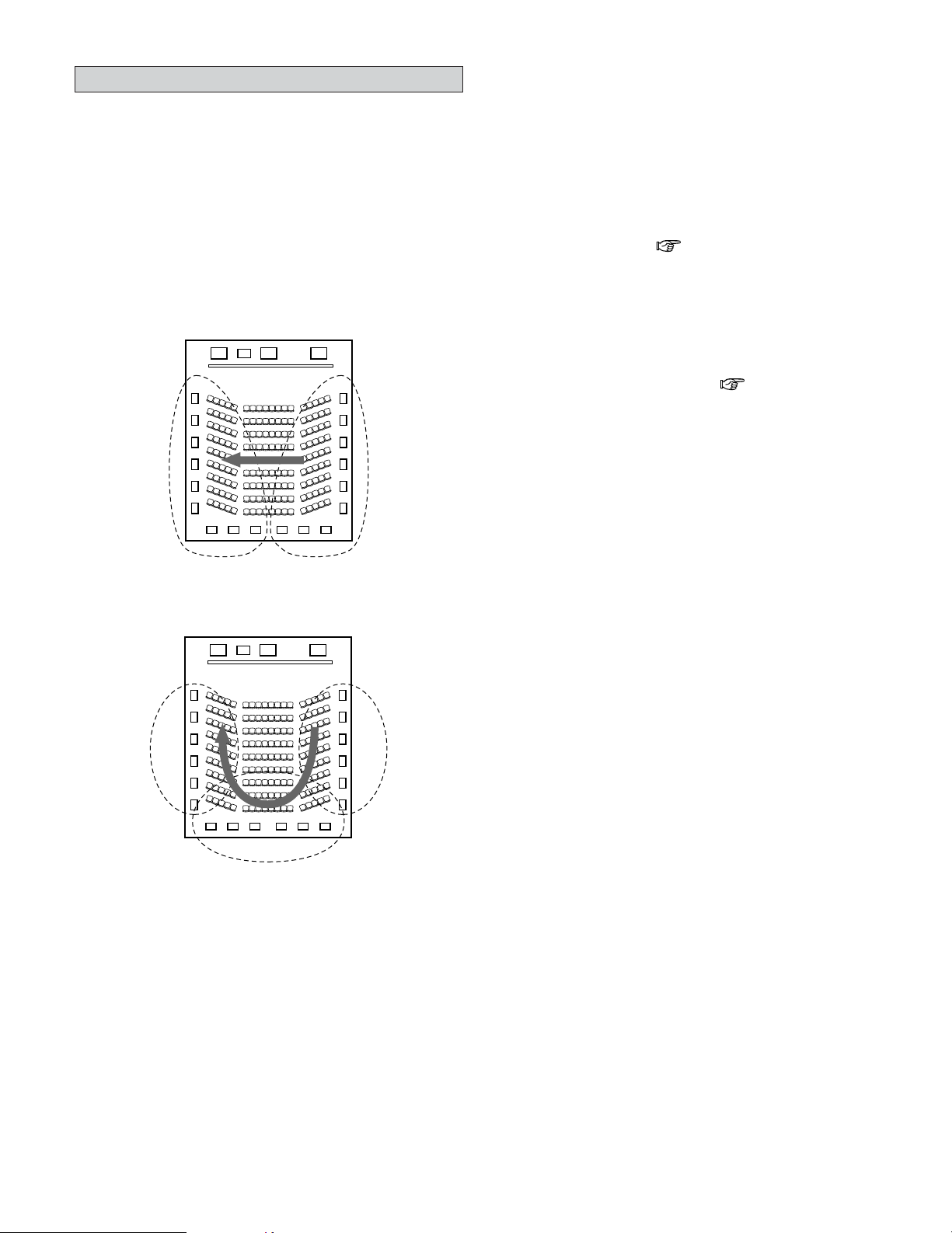
160
Additional Information
Surround back speakers
The THX Surround EX format adds new “Surround Back” (SB)
channels to the conventional 5.1 channel system. This makes
it easy to achieve sound positioned directly behind the
listener, something that was previously difficult with sources
designed for conventional multi surround speakers. In
addition, the acoustic image extending between the sides and
the rear is narrowed, thus greatly improving the expression of
the surround signals for sounds moving from the sides to the
back and from the front to the point directly behind the
listening position.
FL C
SW
FR
SR chSL ch
Change of positioning and acoustic image
with 5.1 channel systems
Movement of acoustic image from SR to SL
FL C
SW
FR
SL ch SR ch
SB ch
Change of positioning and acoustic image
with THX Surround EX system
Movement of acoustic image from SR to SB to SL
Speaker(s) for one or two channels are required in order to
achieve a THX Surround EX system with the AVR-5805CI.
Adding these, however, allows you to achieve stronger
surround effects not only with sources recorded in THX
Surround EX, but also with conventional 2- to 5.1 channel
sources. The WIDE SCREEN mode is a mode for achieving
surround sound with up to 7.1 channels using surround back
speakers, for sources recorded in conventional Dolby
Surround as well as Dolby Digital 5.1 channel and DTS
Surround 5.1 channel sources. Furthermore, all the Denon
original surround modes ( page 61 ~ 63) are compatible
with 7.1 channel playback, so you can enjoy 7.1 channel sound
with any signal source.
2
Numbers and types of surround back speakers
With THX Surround EX, the surround back channel
consists of one channel of playback signals, but we
recommend using two speakers. The modes that use the
new ASA technology from THX ( page 165) are most
effective when using two monopole type surround back
speakers placed close together.
Using two speakers results in a smoother blend with the
sound of the surround channels and better sound
positioning of the surround back channel when listening
from a position other than the center.
2
Placement of the surround left and right
channels when using surround back speakers
Using surround back speakers greatly improves the
positioning of the sound at the rear. Because of this, the
surround left and right channels play an important role in
achieving a smooth transition of the acoustic image from
the front to the back. As shown on the diagram above, in
a movie theater the surround signals are also produced
from diagonally in front of the listeners, creating an
acoustic image as if the sound were floating in space.
To achieve these effects, we recommend placing the
speakers for the surround left and right channels slightly
more towards the front than with conventional surround
systems. Doing so sometimes increases the surround
effect when playing conventional 5.1 channel sources in
the THX Surround EX mode. Check the surround effects of
the various modes before selecting the surround mode.

161
Additional Information
Speaker setting examples
Here we describe a number of speaker settings for different
purposes. Use these examples as guides to set up your
system according to the type of speakers used and the main
usage purpose.
[1] For THX Surround EX systems
(using surround back speakers)
q Basic setting for primarily watching movies
This is recommended when mainly playing movies and
using regular single way or 2-way speakers for the surround
speakers.
Subwoofer
Surround back speakers
Front speakers
45°
Monitor
Center speaker
[ As seen from above ]
Surround
speakers
Surround speaker
Front speaker
2 to 3 feet
[ As seen from the side ]
Surround back
speaker
Point slightly
downwards
• Set the front speakers with their front surfaces as flush
with the TV or monitor screen as possible. Set the center
speaker between the front left and right speakers and no
further from the listening position than the front speakers.
• Consult the operating instructions for your subwoofer for
advice on placing the subwoofer within the listening room.
• If the surround speakers are direct-radiating (monopolar)
then place them slightly behind and at an angle to the
listening position and parallel to the walls at a position 2 to
3 feet (60 to 90 centimeters) above ear level at the prime
listening position.
Surround back speakers
[ As seen from above ]
Surround
speakers
Surround speaker
Front speaker
2 to 3 feet
[ As seen from the side ]
Surround back
speaker
Point slightly
downwards
Path of the surround sound from the
speakers to the listening position
• When using two surround back speakers, set them at the
back facing front and with both speakers at the same
distance from the listening point. When using one
surround back speaker, place it at the rear center facing the
front at a slightly higher position (0 to 0.7 feet) than the
surround speakers.
•We recommend installing the surround back speaker(s) at
a slightly downward facing angle. This effectively prevents
the surround back channel signals from reflecting off the
monitor or screen at the front center, resulting in
interference and making the sense of movement from the
front to the back less sharp.
• Connect the surround speakers to the surround speaker A
terminals on the AVR-5805CI and set settings on the setup
menu to “A”. (This is the factory default setting ( page
153))
w Setting for primarily watching movies using
diffusion type speakers for the surround
speakers
For the greatest sense of surround sound envelopment,
diffuse radiation speakers such as bipolar types, or dipolar
(THX) types, provide a wider dispersion than is possible to
obtain from a direct radiating speaker (monopolar). Place
these speakers at either side of the prime listening
position, mounted above ear level.
162
Additional Information
• Set the front speakers, center speaker and subwoofer in
the same positions as in example q.
• It is best to place the surround speakers directly at the side
or slightly to the front of the viewing position, and 2 to 3
feet (60 to 90 centimeters) above the ears.
• Same as surround back speaker installation method q.
• Connect the surround speakers to the surround speaker A
terminals on the AVR-5805CI and set settings on the setup
menu to “A”. (This is the factory default setting ( page
153))
• The signals from the surround channels reflect off the
walls as shown on the diagram at the left, creating an
enveloping and realistic surround sound presentation.
For multi-channel music sources however, the use of
bipolar or dipolar speakers mounted at the sides of the
listening position may not be satisfactory in order to create
a coherent 360 degree surround sound field. Connect
another pair of direct radiating speakers as described in
example e and place them at the rear corners of the room
facing towards the prime listening position.
e When using different surround speakers for
movies and music
To achieve more effective surround sound for both movies
and music, use different sets of surround speakers and
different surround modes for the two types of sources.
Subwoofer
Surround back speakers
Front speakers
45 ~ 60°
Monitor
Center speaker
[ As seen from above ]
Surround
speakers A
Surround
speakers A
Front speaker
2 to 3 feet
[ As seen from the side ]
Surround back
speaker
Point slightly
downwards
140°
Surround speakers B
Surround speakers B
• Set the front speakers slightly wider apart than the setup
for watching movies only and point them toward the
listening position in order assure clear positioning of the
sound.
• Set the center speaker in the same positions as in example
q).
• Set surround speakers A for watching movies in the
positions described in example q or w, depending on the
types of speakers used.
• Set surround speakers B for playing multi-channel music at
the same height as the front speakers and slightly at an
angle to the rear of the listening position, and point them
toward the listening position.
• Connect the surround speakers for watching movies to the
surround speaker A terminals on the AVR-5805CI, the
surround speakers for playing multi-channel music to the
surround speaker B terminals. Set the surround speaker
selection on the setup menu. (For instructions ( page
146, 147))
•To activate the appropriate speakers for movies and music,
we suggest that during setup, choose Dolby Digital/DTS
with THX and Surround Speakers A (the bipolar or dipolar
speakers mounted at the sides of the listening position).
Choose Dolby Digital/DTS without THX and Surround
Speakers B (the direct radiating speakers mounted at the
rear corners of the listening room). Then, by simply
activating the THX function (used during movie playback,
the Surround A speakers are automatically activated. For
multi-channel music listening (Dolby Digital or DTS music
programs), turn off the THX enhancements by touching
the THX button on the remote control, and the Surround B
speakers will be automatically activated.
Example: Movie sources (Dolby, DTS Surround, etc.)
“THX” or “THX 5.1” mode
…
Speakers A
Music sources (DVD video, DTS CD, etc.)
“Dolby/DTS Surround”
…
Speakers B
The speakers can be switched at the touch of a button
by turning HOME THX CINEMA on when playing
movies and off when playing multi-channel music.
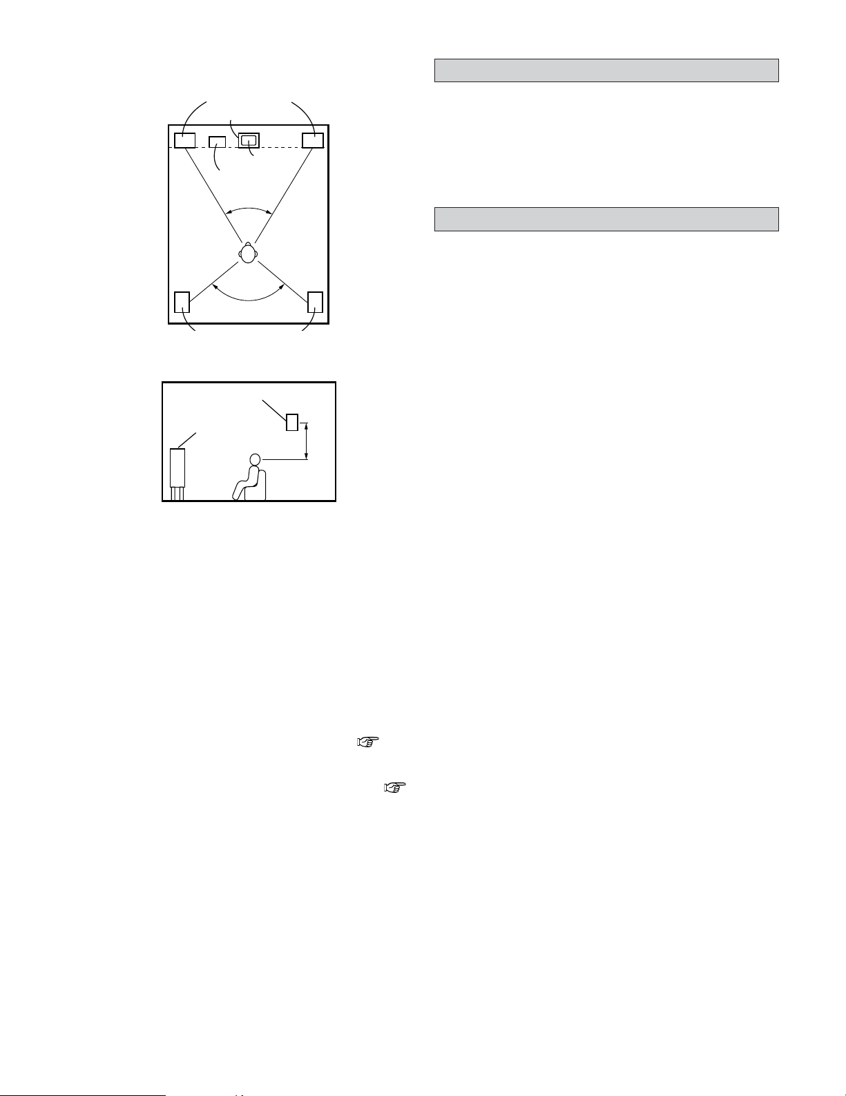
163
Additional Information
[2] When not using surround back speakers
Subwoofer
Surround speakers
Front speakers
45°
Monitor
Center speaker
[ As seen from above ]
Front speaker
2 to 3 feet
[ As seen from the side ]
Surround speaker
• Set the front speakers with their front surfaces as flush
with the TV or monitor screen as possible. Set the center
speaker between the front left and right speakers and no
further from the listening position than the front speakers.
• Consult the operating instructions for your subwoofer for
advice on placing the subwoofer within the listening room.
• If the surround speakers are direct-radiating (monopolar)
then place them slightly behind and at an angle to the
listening position and parallel to the walls at a position 2 to
3 feet (60 to 90 centimeters) above ear level at the prime
listening position.
• Connect the surround speakers to the surround speaker A
terminals on the AVR-5805CI and set settings on the setup
menu to “A”. (This is the factory default setting ( page
153))
• The surround speakers can be switched freely during
playback with the surround parameter adjustment (
page 45).
120°
Surround
Dolby Surround
The AVR-5805CI is equipped with a digital signal processing
circuit that lets you play program sources in the surround
mode to achieve the same sense of presence as in a movie
theater.
[1] Dolby Digital
Dolby Digital is the multi-channel digital signal format
developed by Dolby Laboratories.
A total of 5.1 channels are played: 3 front channels (“FL”,
“FR” and “C”), 2 surround channels (“SL” and “SR”) and the
“LFE” channel for low frequencies.
Because of this, there is no crosstalk between channels and a
realistic sound field with a “three-dimensional” feeling (sense
of distance, movement and positioning) is achieved.
A real, overpowering sense of presence is achieved when
playing movie sources in AV rooms as well.
[2] Dolby Pro Logic II
Dolby Pro Logic II is a matrix decoding technology developed
by Dolby Laboratories. Regular music such as that on CDs is
encoded into 5 channels to achieve an excellent surround
effect.
The surround channel signals are converted into stereo and
full band signals (with a frequency response of 20 Hz to 20
kHz or greater) to create a “three-dimensional” sound image
offering a rich sense of presence for all stereo sources.
[3] Dolby Pro Logic IIx
Dolby Pro Logic IIx is a further improved version of the Dolby
Pro Logic
II matrix decoding technology.
Audio signals recorded in 2 channels are decoded to achieve a
natural sound with up to 7.1 channels.
There are three modes: “Music” suited for playing music,
“Cinema” suited for playing movies, and “Game” which is
optimum for playing games.
[4] Dolby Headphone
This is a three-dimensional sound technology developed jointly
by Dolby Laboratories and Lake Technology Ltd. of Australia
for achieving surround sound using regular headphones.
Previously, when using headphones all the sounds resonated
inside the head and it was uncomfortable to listen with
headphones for long periods of time. Dolby Headphone
simulates speaker playback in a room and places the sound at
the front or the sides, outside the head, to achieve a powerful
sound like the sound of movie or home theaters. This
technology is mainly for multichannel audio/video equipment
with Dolby Digital or Dolby Pro Logic Surround decoding
functions and works with a high performance digital signal
processing (DSP) chip.
Dolby Headphone is effective not only for multichannel
sources but also for stereo programs.
On the AVR-5805CI, it is possible to output signals encoded in
the Dolby Headphone mode from the recording output
terminal and record them on a separate recorder.
164
Additional Information
2 Sources recorded in Dolby Surround
Sources recorded in Dolby Surround are indicated with the
following logo marks.
Dolby Surround support mark:
Manufactured under license from Dolby Laboratories.
“Dolby”, “Pro Logic” and the double-D symbol are
trademarks of Dolby Laboratories.
DTS Digital Surround
DTS Digital Surround is a digital surround format developed by
Digital Theater Systems of the United States.
The number of playback channels and the playing band is the
same as for Dolby Digital (5.1 channels).
The compression rate of the audio data when it was recorded
on the medium is lower than for Dolby Digital, so there is
more information when the data is decoded, resulting in
richer, clearer sound quality.
MANUFACTURED UNDER LICENSE FROM DIGITAL
THEATER SYSTEMS, INC.
U.S. PAT. NO’S. 5,451,942; 5,956,674; 5,974,380;
5,978,762; 6,226,616; 6,487,535 AND OTHER U.S. AND
WORLD–WIDE PATENTS ISSUED AND PENDING.
“DTS”, “DTS–ES”, “Neo:6”, AND “DTS 96/24” ARE
TRADEMARKS OF DIGITAL THEATER SYSTEMS, INC. ©
1996, 2003 DIGITAL THEATER SYSTEMS, INC. ALL
RIGHTS RESERVED.
DTS-ES™
DTS-ES is a new surround format developed by Digital Theater
Systems.
A sound image and sense of positioning can be achieved by
adding a surround back (“SB”) channel to the conventional 5.1
channels.
DTS-ES™ Discrete 6.1:
This is the latest format, in which all 6.1 channels, including
the “SB” channel, are recorded independently. Since the
different channels are independent, the sound can be
designed with total freedom.
DTS-ES™ Matrix 6.1:
With this format, the “SB” channel is matrix-encoded and
inserted into the “SL” and “SR” channels, then decoded for
the “SL”, “SR” and “SB” channels upon playback. This
achieves a surround sound more faithful to the artist’s sound
design intentions than with conventional 5.1 or 6.1 channel
systems.
DTS 96/24
DTS 96/24 is a multi-channel digital signal format developed by
Digital Theater Systems.
The sampling frequency is raised to achieve 5.1 channel
playback with high quality sound (sampling frequency: 96 kHz,
quantization: 24 bits).
DTS NEO:6 surround
This is a matrix decoding technology for 6.1 channel surround
playback of 2 channel sources.
The optimum decoding for the type of signal source to be
played can be selected. There are two modes.
DTS NEO:6 CINEMA:
This mode is suited for playing movies. It achieves the same
type of sound as in a movie theater, even with 2 channels.
DTS NEO:6 MUSIC:
This mode is suited for playing music. A natural sense of
expansion is added to the sound field.
Home THX Cinema Surround
THX is an exclusive set of standards and technologies
established by the world-renowned film production company,
Lucasfilm Ltd. THX grew from George Lucas’ personal desire
to make your experience of the film soundtrack, in both movie
theaters and in your home theater, as faithful as possible to
what the director intended.
Movie soundtracks are mixed in special movie theaters called
dubbing stages and are designed to be played back in movie
theaters with similar equipment and conditions. The
soundtrack created for movie theaters is then transferred
directly onto Laserdisc, VHS tape, DVD, etc., and is not
changed for playback in a small home theater environment.
THX engineers developed patented technologies to accurately
translate the sound from the movie theater environment into
the home, correcting the tonal and spatial errors that occur. On
the AVR-5805CI, when the Home THX Cinema mode is on,
THX post-processing is automatically added after the Dolby
Pro Logic, Dolby Digital or DTS decoder:
Re-EQ™ (Re-Equalization):
The tonal balance of a film soundtrack will be excessively
bright and harsh when played back over audio equipment in
the home because film soundtracks are designed to be
played back in large movie theaters using very different
professional equipment. Re-Equalization restores the correct
tonal balance for listening to a movie soundtrack in a normal
home environment.

165
Additional Information
Timbre Matching™:
The human ear changes our perception of a sound depending
on the direction from which the sound is coming. In a movie
theater, there is an array of surround speakers so that the
surround information is all around you. In a home theater, only
two speakers located to the side of your head are used. The
Timbre Matching feature filters the information going to the
surround speakers so that they more closely match the tonal
characteristics of the sound coming from the front speakers.
This ensures seamless panning between the front and
surround speakers.
Adaptive Decorrelation™:
In a movie theater, a large number of surround speakers help
create an enveloping surround sound experience, while in a
home theater there are usually only two speakers. This can
make the surround speakers sound like headphones that lack
spaciousness and envelopment. The surround sounds will
also collapse into the closest speaker as you move away from
the middle seating position. Adaptive Decorrelation slightly
changes one surround channel’s time and phase relationship
with respect to the other surround channel. This expands the
listening position and creates—with only two speakers—the
same spacious surround experience as in a movie theater.
THX Ultra2™:
Before any home theater component can be THX Ultra2
certified, it must incorporate all the features above and also
pass a rigorous series of quality and performance tests. Only
then can a product feature the THX Ultra2 logo, which is your
guarantee that the Home Theater products you purchase will
give you superb performance for many years to come. THX
Ultra2 requirements cover every aspect of the product
including power amplifier performance, pre-amplifier
performance and operation, as well as hundreds of other
parameters in both the digital and analog domain.
In addition to improvements to the power amplifier with
respect to previous THX Ultra standards, three surround
modes have been added: the THX Ultra2 Cinema mode, THX
Music Mode and THX Games Mode.
THX Ultra2 Cinema:
THX Ultra2 Cinema mode plays 5.1 movies using all 8
speakers giving you the best possible movie watching
experience. In this mode, new THX processing blends the
side surround speakers and back surround speakers
providing the optimal mix of ambient and directional surround
sounds.
DTS-ES (Matrix and 6.1 Discrete) and Dolby Digital Surround
EX encoded soundtracks will be automatically detected in
Ultra2 Cinema mode if the appropriate flag has been
encoded.
Some Dolby Digital Surround EX soundtracks are missing the
digital flag that allows automatic switching. If you know that
the movie that you are watching is encoded in Surround EX,
you can manually select the THX Surround EX playback
mode, otherwise THX Ultra2 Cinema mode will apply
processing to provide optimum replay.
THX Music Mode:
For the replay of 5.1 multi-channel music the THX Music
Mode should be selected. In this mode new THX processing
is applied to the surround channels of all 5.1 encoded music
sources such as DTS and Dolby Digital to provide a wide
stable rear soundstage.
THX Games Mode:
For the replay of stereo and multi-channel game audio the
THX Games Mode should be selected. In this mode THX ASA
processing is applied to the surround channels of all 5.1 and
2.0 encoded game sources such as analog, PCM, DTS and
Dolby Digital. This accurately places all game audio surround
information, providing a full 360 degree playback
environment. THX Games Mode is unique as it gives you a
smooth transition of audio in all points of the surround field.
ASA (Advanced Speaker Array):
ASA is a proprietary THX technology which processes the
sound fed to 2 side and 2 back surround speakers to provide
the optimal surround sound experience. When you set up
your home theater system using all eight speaker outputs
(Left, Center, Right, Surround Right, Surround Back Right,
Surround Back Left, Surround Left and Subwoofer) placing
the two Surround Back speakers close together facing the
front of the room as shown in the diagram will provide the
largest sweet spot. If for practical reasons you have to place
the Surround Back speakers apart, you will need to go THX
Audio Set-up screen and choose the setting that most closely
corresponds to the speaker spacing, which will re-optimize
the surround sound-field.
ASA is used in three new modes; THX Ultra2 Cinema, THX
Music Mode and THX Games Mode.
Boundary Gain Compensation:
If your chosen listening room layout (for practical or aesthetic
reasons) results in the most of the listeners being close to
the rear wall, the resulting bass level can be sufficiently
reinforced by the boundary that the overall sound quality
becomes “boomy”. THX Ultra2 receivers and controllers
contain the BGC (Boundary Gain Compensation) feature to
provide an improved bass balance. BGC can be selected by
choosing “THX Ultra2 Subwoofer–Yes” from the “Boundary
Gain Compensation” section of the THX Audio setup menu.
THX and Re-EQ, THX Timbre Matching, THX Adaptive
Decorrelation, and THX Advanced Speaker Array are
trademarks of THX Ltd. THX may be registered in some
jurisdictions. All rights reserved.
166
Additional Information
HDCD
®
(High Definition Compatible Digital
®
)
HDCD is an encoding/decoding technology that greatly reduces
the distortion that occurs upon digital recording while
maintaining compatibility with the conventional CD format, thus
expanding the dynamic range and achieving a high resolution.
Conventional CDs and HDCD compatible CDs are identified
automatically to select the optimum digital processing.
• ®, HDCD®, High Definition Compatible Digital® and
Microsoft® are either registered trademarks or trademarks
of Microsoft Corporation, Inc. in the United States and/or
other countries. HDCD system manufactured under license
from Microsoft Corporation, Inc. This product is covered by
one or more of the following: In the USA: 5,479,168,
5,638,074, 5,640,161, 5,808,574, 5,838,274, 5,854,600,
5,864,311, 5,872,531, and in Australia: 669114. Other
patents pending.
2 THX™ Surround EX™
In 1999, a new surround system was launched
simultaneously with the release of the movie “Star Wars
Episode I”. “Dolby Digital Surround EX” is a new movie
sound track that greatly enhances the sense of spatial
expression and the positioning of the surround channel
sound. The result is 360 degrees of movement and moving
sound effects that seem to pass right over the listener’s head.
This system was developed jointly by THX and Dolby
Laboratories, fusing THX’s idea of improving spatial
expression and achieving a uniform 360 degree sound
positioning with Dolby Laboratories’ matrix encoding
technology. Emphasis was placed on compatibility with the
existing system Dolby Digital 5.1 channel, and the new
“surround back (SB) channel” was added to achieve
improvements over the conventional 5.1 channel system in
terms of the positioning of the sound at the rear, the
acoustic image of sound moving from the two sides to the
back as well as sound moving from the front to the center
rear with the multi surround speaker systems used in movie
theaters, thereby enabling various types of surround sound.
The surround back channel signal is a matrix-encoded signal
inserted into both the Dolby Digital SL (surround left) and
SR (surround right) channels. Upon playback, the signals
are decoded by a high precision digital matrix decoder
within the Dolby Digital decoder into the SL, SR and SB
channels and output as 6.1 channels of signals. With the
AVR-5805CI, the signals further undergo Home THX
Cinema processing to achieve a THX Surround EX system.
Even without the proper environment for playing the SB
channel, Dolby Digital Surround EX signals are 100%
compatible with existing 5.1 channel playback systems, so
they can be played as such. In this case, the SB channel
signal is produced as a monaural signal from both the SL
and SR channels, so none of the signal components are
missing. The effects specific to THX Surround EX (the
sense of spatial expression and the positioning of the
sound), however, are the same as with conventional 5.1
channel surround systems.
THX and Ultra2 are trademarks of THX Ltd. THX may be
registered in some jurisdictions. All rights reserved. Surround
EX is a trademark of Dolby Laboratories. Used with permission.
Audyssey MultEQ XT
Audyssey MultEQ XT is a technology designed to provide the
optimum listening environment for multiple listeners within the
listening area. Test data collected from multiple listening points
is analyzed comprehensively and equalization that improves the
sound quality for the entire listening area is performed.
Audyssey MultEQ XT not only corrects frequency response
problems in large listening areas, it also fully automates the
surround system setup.
For a detailed description, see page 20.
• Audyssey MultEQ XT is a trademark of Audyssey
Laboratories. It is licensed under US and National Patent
Applications 20030235318 and 10/700,220. Additional U.S.
and Foreign Patents pending. MultEQ and the Audyssey
MultEQ logo are trademarks of Audyssey Laboratories, Inc..
All rights reserved.
About IEEE1394
IEEE1394 is an international standard established by the
“IEEE” (Institute of Electrical and Electronics Engineers) of
the United States.
The AVR-5805CI can be connected to an IEEE1394 compatible
device using an IEEE1394 cable to enable digital transfer of
multi-channel audio sources (DVD Audio discs, Super Audio
CDs, etc.) with a single cable.
• The AVR-5805CI’s transfer format is compatible with A&M
protocol.
In addition to A&M protocol, IEEE1394 transfer formats also
include MPEG-TS, DV, etc.
• The AVR-5805CI is compatible with a data transfer speed of
up to S400.
The IEEE1394 maximum data transfer speeds are defined
as approximately 100, 200 or 400 Mbps, expressed
respectively as S100, S200 and S400. When S100 or S200
devices are connected, the actually transfer rate may be
slower than 400 Mbps, depending on the device’s
specifications. As far as possible, interconnect devices with
the same maximum data transfer rate.
• The AVR-5805CI is compatible with the DTCP (Digital
Transmission Content Protection) system.
2
Copyright protection system
In order to play the sound of DVD Audio discs, Super Audio
CDs or DVDs (aside from freely copiable discs) using
IEEE1394 connections, both the player and receiver must
be compatible with the DTCP (Digital Transmission
Content Protection) system.
DTCP is a copy protection technology that involves data
encryption and authentication of the other device. Refer to
your player’s operating instructions.
167
Additional Information
Windows Media Connect
This is a media server provided free of charge by Microsoft
since October 2004.
It operates with all types of music jukebox programs, but is
optimum with Windows Media Player Ver. 10.
Windows Media Connect can be used to play playlists created
on jukebox software such as Windows Media Player Ver. 10,
as well as WMA, DRM WMA, MP3 and WAV files.
About HDMI
“HDMI” is the abbreviation of “High-Definition Multimedia
Interface”.
This is a digital interface standard for next generation TVs
developed based on the DVI (Digital Visual Interface) used for
computer displays, etc., and optimized for use in non-
professional equipment. With it, non-compressed digital video
and multi-channel audio signals can be transferred with a
single connector, eliminating the need to use separate cables
for the picture and sound and making it possible to make
connectors smaller. HDMI is also compatible with HDCP
(High-bandwidth Digital Contents Protection), a technology for
protecting copyrights that encrypts digital video signals in the
same was as with DVI.
• HDMI, the HDMI logo and High-Definition Multimedia
Interface are trademarks or registered trademarks of HDMI
Licensing LLC.
2 Explanation for installing Windows Media
Connect
1. If installation of Windows XP Service Pack 2 is not yet
complete, either download free of charge from Microsoft
or via the Windows Update installer.
2. Download the latest version of Windows Media Player Ver.
10 either directly from Microsoft or using the Windows
Update installer.
3. Download Windows Media Connect (usable since October
12, 2004) either directly from Microsoft or using the
Windows Update installer.
vTuner
This is an Internet radio free online contents server. Note that
usage fess are included in upgrade costs.
For inquiries about this service, visit the vTuner site below.
vTuner website: http://www
.radiodenon.com
This product is protected by certain intellectual property rights
of Nothing Else Matters Software and BridgeCo. Use or
distribution of such technology outside of this product is
prohibited without a license from Nothing Else Matters
Software and BridgeCo or an authorized subsidiary.
The AVR-5805CI’s IEEE1394 device interface is designed
based on the standards below.
1) IEEE Std. 1394a-2000, Standard for High Performance
Serial Bus
2) Audio and Music Data Transmission Protocol 2.0
It is compatible with IEC60958 bit stream, DVD-Audio and
Super Audio CD within AM824 sequence adaptation layers
within these standards.
DENON LINK
DENON LINK is a DENON-exclusive digital link for transmitting
high speed, high sound quality digital audio signals with no
loss in of signal.
High quality sound playback is possible by connecting to a
DENON DVD player with a DENON LINK terminal.
Advanced AL24 Processing
2 Equipped with “Advanced AL24 Processing”
– time base area data quantity extension
In addition to “AL24 Processing Plus”, the conventional bit
extension technology, the PCM signal (CD/digital) playback
system also includes the newly developed “Advanced
AL24 Processing”, a unique high speed signal detection
and processing technology that greatly improves the
amount of data in the time base area. In addition to
extension of the original 16-bit data into 24 bits,
“Advanced AL24 Processing” conducts data interpolation
on the time axis, in other words up-convert sampling, to
achieve natural interpolation processing without harming
the original data. In addition, the digital filter offers
expanded flexibility, including pulse response with no
ringing. Optimum filtering processing is performed even
for pulsive music data and attack sounds. All this makes it
possible to recreate the delicate nuances of the music and
such space information as the positions of the performers,
the width, height and depth of the place of the
performance (stage), and so on.
Windows Media DRM
A copyright-protected technology developed by Microsoft.
• The PlaysForSure logo, Windows Media and the Windows
logo are trademarks or registered trademarks of Microsoft
Corporation in the United States and/or other countries.
• Content providers are using the digital rights management
technology for Windows Media contained in this device
(“WM-DRM”) to protect the integrity of their content
(“Secure Content”) so that their intellectual property,
including copyright, in such content is not misappropriated.
This device uses WM-DRM software to play Secure
Content (“WM-DRM Software”). If the security of the WM-
DRM Software in this device has been compromised,
owners of Secure Content (“Secure Content Owners”) way
request that Microsoft revoke the WM-DRM Software's
right to acquire new licenses to copy, display and/or play
Secure Content. Revocation does not alter the WM-DRM
Software’s ability to play unprotected content. A list of
revoked WM-DRM Software is sent to your device
whenever you download a license for Secure Content from
the Internet or from PC. Microsoft may, in conjunction with
such license, also download revocation list onto your device
on behalf of Secure Content Owners.

Surround Mode
168
Additional Information
Surround modes and parameters
C : Signal / Adjustable
E : No signal / Not adjustable
B :Turned on or off by speaker configuration setting
C : Able
E : Unable
NOTE1 : BASS +6 dB, TREBLE 0 dB
NOTE2 : BASS +6 dB, TREBLE +4 dB
NOTE3 : This parameter is availabe when the “MODE” is set to “CINEMA”.
NOTE4 : This parameter is availabe when the “MODE” is set to “CINEMA” or “PL”.
*1:
When playing Dolby Digital and DTS signals.
*2:
When playing Dolby Digital, DTS, DVD-Audio and Super Audio CD.
E
E
E
E
E
E
E
E
C (PL
IIx C)
E
C (CINEMA)
C (CINEMA))
C (CINEMA)
E
E
E
E
E
E
E
E
E
E
E
E
E
E
E
E
E
E
C (OFF)
E
E
C (NOTE3)
C (NOTE4)
C (NOTE3)
C (OFF)
C (OFF)
E
E
E
E
E
E
E
E
E
E
E
E
E
C (0 dB)
E
C (0 dB)
C (0 dB)
E
E
C (0 dB)
C (0 dB)
C (0 dB)
C (0 dB)
C (0 dB)
C (0 dB)
C (NOTE1)
C (NOTE2)
C (0 dB)
C (0 dB)
C (0 dB)
C (0 dB)
C (0 dB)
C (0 dB)
E
E
C
C
E
E
C
C
C
C
C
C
C
C
C
C
C
C
C
C
C
C
C
E
E
E
E
C (ON)
E
E
C (ON)
E
E
C (ON)
E
E
E
C (ON)
C (ON)
E
E
E
E
E
E
E
E
E
C (0 dB)
C (0 dB)
C (0 dB)
C (0 dB)
C (0 dB)
E
C (0 dB)
C (0 dB)
E
C (0 dB)
E
E
E
C (0 dB)
C (0 dB)
C (0 dB)
C (0 dB)
C (0 dB)
C (0 dB)
C (0 dB)
C (0 dB)
C (0 dB)
C (0 dB)
C (0 dB)
C (OFF)
E
E
E
C (OFF)
E
E
C (OFF)
E
E
C (OFF)
C (OFF)
C (OFF)
C (OFF)
C (OFF)
C (OFF)
C (OFF)
C (OFF)
C (OFF)
C (OFF)
C (OFF)
C (OFF)
C (OFF)
C (OFF)
B
B
B
B
B
B
B
B
B
B
B
B
B
B
B
B
B
B
B
B
B
B
B
B
E
E
B
B
E
B
B
B
B
B
B
E
B
B
B
B
B
B
B
B
B
B
B
E
E
E
B
B
E
B
B
B
B
B
B
B
B
B
B
B
B
B
B
B
B
B
B
E
C
C
C
C
C
C
C
C
C
C
C
C
C
C
C
C
C
C
C
C
C
C
C
C
SURROUND
L/R
Signals and adjustability in the different modes
Channel output
Parameter (default values are shown in parentheses)
SUB-
WOOFER
D. COMP
*1
LFE
*2
AFDM
*2
SB CH OUT
(MODE)
TONE
CONTROL
CINEMA
EQ.
MODE
(DECODER)
ROOM
SIZE
E
E
B
B
E
B
B
B
B
B
B
B
B
B
B
B
B
B
B
B
B
B
B
E
E
E
E
E
E
E
E
E
E
E
E
E
E
E
E
E
C (Medium)
C (Medium)
C (Medium)
C (Medium)
C (Medium)
C (Medium)
E
E
EFFECT
LEVEL
E
E
E
E
E
E
E
C (ON, 10)
E
E
E
E
E
E
E
E
C (10)
C (10)
C (10)
C (10)
C (10)
C (10)
E
E
PURE DIRECT, DIRECT
DSD DIRECT
DSD MULTI DIRECT
MULTI CH DIRECT
STEREO
EXT. IN
MULTI CH IN
WIDE SCREEN
HOME THX CINEMA (2ch)
HOME THX CINEMA (5.1ch)
DOLBY PRO LOGIC
IIx
DOLBY PRO LOGIC
II
DTS NEO:6
DOLBY DIGITAL
DTS SURROUND
9CH STEREO
SUPER STADIUM
ROCK ARENA
JAZZ CLUB
CLASSIC CONCERT
MONO MOVIE
VIDEO GAME
MATRIX
VIRTUAL
FRONT L/R
CENTER
SURROUND
BACK L/R

Surround Mode
169
Additional Information
PURE DIRECT, DIRECT
DSD DIRECT
DSD MULTI DIRECT
MULTI CH DIRECT
STEREO
EXT. IN
MULTI CH IN
WIDE SCREEN
HOME THX CINEMA (2ch)
HOME THX CINEMA (5.1ch)
DOLBY PRO LOGIC
IIx
DOLBY PRO LOGIC
II
DTS NEO:6
DOLBY DIGITAL
DTS SURROUND
9CH STEREO
SUPER STADIUM
ROCK ARENA
JAZZ CLUB
CLASSIC CONCERT
MONO MOVIE
VIDEO GAME
MATRIX
VIRTUAL
C : Signal / Adjustable
E : No signal / Not adjustable
B :Turned on or off by speaker configuration setting
E
E
E
E
E
C
E
E
E
E
E
E
E
E
E
E
E
E
E
E
E
E
E
E
E
E
E
E
E
E
E
E
E
E
E
E
C (0.3)
E
E
E
E
E
E
E
E
E
E
E
E
E
E
E
E
E
E
E
E
E
C (3)
C (3)
E
E
E
E
E
E
E
E
E
E
E
E
E
E
E
E
E
E
E
E
E
E
C (3)
C (3)
E
E
E
E
E
E
E
E
E
E
E
E
C
C
E
E
E
E
E
E
E
E
E
E
E
E
E
E
E
E
E
E
E
E
E
E
E
E
E
E
E
E
E
E
E
E
E
E
E
E
E
E
E
E
E
E
E
E
C (30 msec)
E
DELAY TIME
PANORAMA
Signals and adjustability in the different modes
Parameter (default values are shown in parentheses)
SUBWOOFER
ON/OFF
DIMENSION
CENTER
WIDTH
CENTER
IMAGE
SW ATT
E
E
E
E
E
E
E
E
E
E
C (OFF)
C (OFF)
E
E
E
E
E
E
E
E
E
E
E
E
PRO LOGIC
II/IIx MUSIC MODE only
NEO:6 MUSIC
MODE only
EXT. IN only
NIGHT
mode
C (OFF)
E
E
E
C (OFF)
E
E
C (OFF)
C (OFF)
C (OFF)
C (OFF)
C (OFF)
C (OFF)
C (OFF)
E
C (OFF)
C (OFF)
C (OFF)
C (OFF)
C (OFF)
C (OFF)
C (OFF)
C (OFF)
C (OFF)
Dolby Digital

170
Additional Information
2 Differences in surround mode names depending on the input signals
E
E
C
C
C
C
C
C
E
E
E
E
E
E
E
E
E
E
E
E
E
E
E
E
E
E
E
E
E
E
E
4
C
C
E
E
E
E
E
C
E
C
C
C
C
E
E
E
E
E
E
E
C
C
E
E
E
E
C
C
C
C
C
C
C
E
E
E
E
E
C
C
C
C
C
C
E
E
E
E
E
E
E
E
E
E
E
E
E
E
E
E
E
E
E
E
E
E
E
4
C
C
E
E
E
E
E
C
E
C
C
C
C
E
E
E
E
E
E
E
C
C
E
E
E
E
C
C
C
C
C
C
C
E
E
E
E
E
E
E
E
C
E
C
C
C
C
E
E
E
E
E
E
E
C
C
E
E
E
E
4
C
C
C
C
C
C
E
E
E
E
E
C
C
C
C
C
C
E
E
E
E
E
E
E
E
E
E
E
E
C
4
C
C
E
E
E
E
E
E
E
E
E
E
E
E
C
C
C
C
C
C
E
E
E
E
E
E
E
E
E
E
E
E
C
4
C
C
E
E
E
E
E
E
E
E
E
E
E
E
B
C
C
C
C
C
E
E
E
E
E
E
E
E
E
E
E
E
C
C
4 B
C
E
E
E
E
E
E
E
E
E
E
E
E
C
C
C
C
C
C
E
E
E
E
E
E
E
E
E
E
E
E
C
4
C
C
E
E
E
E
E
E
E
E
E
E
E
C
E
C
C
C
C
C
E
E
E
E
E
E
4
C
C
C
E
E
E
E
E
E
E
E
E
E
E
E
E
E
E
E
E
C
E
C
C
C
C
C
E
E
E
E
E
4
E
C
C
C
E
E
E
E
E
E
E
E
E
E
E
E
E
E
E
E
E
B
E
C
C
C
C
C
E
E
E
E
4 B
C
E
C
C
C
E
E
E
E
E
E
E
E
E
E
E
E
E
E
E
E
B
E
E
C
C
C
C
C
E
E
E
4 B
E
C
E
C
C
E
E
E
E
E
E
E
E
E
E
E
E
E
E
E
E
E
E
E
E
E
E
C
E
C
C
C
C
E
E
E
E
E
E
E
C
C
E
E
E
E
C
C
C
C
C
C
C
E
E
E
E
E
E
E
E
C
E
C
C
C
C
E
E
E
E
E
E
E
C
C
E
E
E
E
C
C
C
C
C
C
C
E
E
E
*1
*1
*1
*2
*2
*2
*4
*1
*1
*2
*1
*1
*1
*2
*1
*2
*1
Surround Mode
Super Audio CD
Button
Note
DTS ES DSCRT
(With Flag)
Input signals
DTS
DOLBY DIGITAL
HOME THX CINEMA
STANDARD
DTS SURROUND
DTS ES DSCRT6.1
DTS ES MTRX6.1
DTS SURROUND
DTS 96/24
DTS + PL
IIx CINEMA
DTS + PL
IIx MUSIC
DTS + NEO:6
DTS NEO:6 CINEMA
DTS NEO:6 MUSIC
DOLBY SURROUND
DOLBY DIGITAL EX
DOLBY DIGITAL
DOLBY DIGITAL+PL
IIx CINEMA
DOLBY DIGITAL+PL
IIx MUSIC
DOLBY PRO LOGIC
IIx CINEMA
DOLBY PRO LOGIC
IIx MUSIC
DOLBY PRO LOGIC
IIx GAME
DOLBY PRO LOGIC
II CINEMA
DOLBY PRO LOGIC
II MUSIC
DOLBY PRO LOGIC
II GAME
DOLBY PRO LOGIC
MULTI CH IN
MULTI CH IN
MULTI IN + PL
IIx CINEMA
MULTI IN + PL
IIx MUSIC
ANALOG
LINEAR
PCM
DTS ES MTRX
(With Flag)
DTS
(5.1ch)
DTS
96/24
DOLBY DIGITAL EX
(With Flag)
DOLBY DIGITAL
EX
(With no Flag)
DOLBY
DIGITAL
(5.1ch)
DOLBY
DIGITAL
(3, 4, 5ch)
DOLBY
DIGITAL
(2ch)
DVD-AUDIO
DVD-Audio
(multi ch)
DVD-
Audio
(2ch)
176.4/
192kHz
DSD
(multi ch)
DSD
(2ch)
E
E
E
E
E
C
E
C
C
C
C
E
E
E
E
E
E
E
C
C
E
E
E
E
C
C
C
C
C
C
C
E
E
E
ES DSCRT6.1 + THX
ES MTRX6.1 + THX
THX SURROUND EX
THX Ultra2 Cinema
THX Music Mode
THX Games mode
THX 5.1
PL
IIx C + THX
PL
II C + THX
DOLBY PL + THX
NEO:6 + THX
Button
171
Additional Information
Surround Mode
Super Audio CD
Note
DTS ES DSCRT
(With Flag)
Input signals
DTS
DOLBY DIGITAL
ANALOG
LINEAR
PCM
DTS ES MTRX
(With Flag)
DTS
(5.1ch)
DTS
96/24
DOLBY DIGITAL EX
(With Flag)
DOLBY DIGITAL
EX
(With no Flag)
DOLBY
DIGITAL
(5.1ch)
DOLBY
DIGITAL
(3, 4, 5ch)
DOLBY
DIGITAL
(2ch)
DVD-AUDIO
DVD-Audio
(multi ch)
DVD-
Audio
(2ch)
176.4/
192kHz
DSD
(multi ch)
DSD
(2ch)
E
E
C
C
C
C
E
E
C
C
C
C
C
C
C
C
C
C
C
C
C
C
C
C
E
E
E
E
E
C
E
E
E
E
E
C
C
C
C
C
C
C
C
C
C
4
E
E
E
C
C
C
E
E
E
C
C
C
C
C
C
C
C
C
C
C
C
C
C
C
E
E
E
E
E
C
E
E
E
E
E
C
C
C
C
C
C
C
C
C
C
4
C
E
E
E
E
E
C
E
E
E
E
E
C
C
C
C
C
C
C
C
C
C
C
C
E
E
E
E
E
C
E
E
E
E
E
C
C
C
C
C
C
C
C
C
C
C
C
E
E
E
E
E
C
E
E
E
E
E
C
C
C
C
C
C
C
C
C
C
C
C
E
E
E
E
E
C
E
E
E
E
E
C
C
C
C
C
C
C
C
C
C
C
C
E
E
E
E
E
C
E
E
E
E
E
C
C
C
C
C
C
C
C
C
C
C
C
E
E
E
E
E
C
E
E
E
E
E
C
C
C
C
C
C
C
C
C
C
C
C
E
E
E
E
E
C
E
E
E
E
E
C
C
C
C
C
C
C
C
C
C
C
C
E
E
E
E
E
C
E
E
E
E
E
C
C
C
C
C
C
C
C
C
C
C
C
E
E
E
E
E
C
E
E
E
E
E
C
C
C
C
C
C
C
C
C
C
4
C
E
E
E
E
E
C
E
E
E
E
E
C
C
C
C
C
C
C
C
C
C
4
*2
*1
*2
*1
*3
DIRECT
DIRECT
DSD DIRECT
DSD MULTI DIRECT
MULTI CH DIRECT
M DIRECT + PL
IIx CINEMA
M DIRECT + PL
IIx MUSIC
PURE DIRECT
PURE DIRECT
DSD PURE DIRECT
DSD MULTI PURE
MULTI CH PURE DIRECT
M PURE D + PL
IIx CINEMA
M PURE D + PL
IIx MUSIC
DSP SIMULATION
WIDE SCREEN
SUPER STADIUM
ROCK ARENA
JAZZ CLUB
CLASSIC CONCERT
MONO MOVIE
VIDEO GAME
MATRIX
VIRTUAL
9CH STEREO
STEREO
STEREO
C
E
E
E
E
E
C
E
E
E
E
E
C
C
C
C
C
C
C
C
C
C
C
E
C
E
E
E
E
E
C
E
E
E
E
C
C
C
C
C
C
C
C
C
C
4
4 : Mode selectable in initial status
B : Mode fixed when AFDM is ON
C : Selectable mode
E : Non-selectable mode
NOTE :
*1: This mode is not available when the Surround Back speaker setup is set to “None”.
*2: This mode is not available when the Surround Back speaker setup is set to “1spkr” or “None”.
*3: If the Surround Back speaker setup is set to “None” and/or the surround (B) speaker setup is set to “None”,
then “7CH STEREO” or “5CH STEREO” is displayed.
*4: For input signals other than 2 channel signals, this mode cannot be selected when surround back speaker is
set to “1spkr” or “None”.
S-VIDEO
172
Additional Information
Relationship between the video input signal and monitor output according to the video convert mode
settings of MAIN ZONE
EE
: Not output
✳1:On screen display superimposed on video signal and output.
✳2:On screen display superimposed on S-Video signal and output.
✳3:Video signals are not output when the analog to HDMI convert function is set
to “ON”.
: On screen display only displayed for SYSTEM SETUP, SURROUND PARAMETER
(except the HDMI monitor out) and ON SCREEN button.
: When “OFF” is selected for the “Analog to HDMI Convert” setting, no video
signals other than the HDMI input signal are output.
:Including the contents of and above.
• HDMI MONITOR OUT:
When there is no HDMI input signal and “HDMI” is selected for the “Scaler” setting,
the signal is output as set with the “Resolution” setting.
When “Component” is selected for the “Scaler” setting, the signal is output with the
same resolution as the input signal.
• COMPONENT MONITOR OUT:
When “Component” is selected for the “Scaler” setting, the signal is output as set
with the “Resolution” setting. However, the output resolution is limited to a
maximum of 480p/576p if the input signal is copyright-protected.
CC
: Signal input
EE
: No signal
480p ~ 720p : 480p/576p/1080i/720p
•
The MAIN ZONE video conversion function is compatible with the following
format: NTSC, PAL, SECAM, NTSC4.43, PAL-N, PAL-M and PAL-60.
• When SECAM signals of video input are up-converted, the signals are
output in PAL format from the S-Video terminal .
• When the input signal is set to component video 1080p, the signals cannot
be output to the HDMI monitor output terminal.
Video convert
VIDEOS-VIDEOCOMPONENTHDMI
MONITOR OUT
VIDEOS-VIDEOCOMPONENTHDMI
Input signals
ON
VIDEO ✳3
S-VIDEO
S-VIDEO
S-VIDEO
S-VIDEO
EE
VIDEO
S-VIDEO
S-VIDEO
COMPONENT
COMPONENT
COMPONENT ✳1
COMPONENT ✳1
S-VIDEO
COMPONENT ✳2
COMPONENT ✳2
S-VIDEO
COMPONENT ✳2
COMPONENT ✳2
EE
EE
EE
EE
CC
(1080p)
CC
(480i/576i)
EE EE
EE CC
CC EE
CC CC
EE EE
CC
(480p ~ 720p)
EE EE
EE EE
EE
EE
EE
EE
EE
EE
EE
VIDEO
S-VIDEO
S-VIDEO
COMPONENT
COMPONENT
EE EE
VIDEO VIDEO
S-VIDEO S-VIDEO
S-VIDEO S-VIDEO
EE EE
COMPONENT
EE EE
COMPONENT COMPONENT
EE
EE
CC
(1080p)
CC
(480p ~ 720p)
CC
(480i/576i)
CC
(480p ~ 720p)
EE CC
EE CC
EE CC
CC
(1080p)
CC EE
CC EE
EE
EE
EE
EE
EE
COMPONENT ✳1
COMPONENT ✳1
COMPONENT ✳1
COMPONENT ✳2
VIDEO VIDEO
VIDEO
COMPONENT ✳1
VIDEO
COMPONENT ✳2
S-VIDEO S-VIDEO
S-VIDEO
VIDEO
CC
(480i/576i)
CC
(1080p)
CC
(480p ~ 720p)
EE
CC EE
CC CC
CC CC
CC
(480i/576i)
CC CC
EE EE
EE
EE
EE
CC
EECC
COMPONENT ✳2
COMPONENT ✳2
COMPONENT ✳2
EE
S-VIDEO
S-VIDEO S-VIDEO
S-VIDEO
COMPONENT ✳2
S-VIDEO
EE EE
HDMI
EE
EE
CC
(480p ~ 720p)
EE CC
CC EE
CC CC
CC
(1080p)
EE EE
EE EE
CC
CC
CC
CC
CC
VIDEO ✳2
S-VIDEO ✳2
S-VIDEO ✳2
COMPONENT
VIDEO VIDEO
S-VIDEO S-VIDEO
S-VIDEO S-VIDEO
COMPONENT
EE EE
EE EE
HDMI
HDMI
HDMI
HDMI
HDMI
CC
(1080p)
CC
(480p ~ 720p)
CC
(480i/576i)
CC
(480p ~ 720p)
EE
EE
CC
EE CC
EE CC
CC
(1080p)
CC EE
CC EE
CC
CC
CC
CC
CC
COMPONENT
COMPONENT ✳1
COMPONENT ✳1
COMPONENT ✳1
COMPONENT ✳2
VIDEO
COMPONENT
VIDEO ✳3
VIDEO
VIDEO
COMPONENT ✳1
VIDEO
COMPONENT ✳2
S-VIDEO S-VIDEO
S-VIDEO S-VIDEO
HDMI ✳1
HDMI
HDMI ✳1
HDMI ✳1
HDMI ✳2
HDMI ✳2
CC
(480i/576i)
CC
COMPONENT ✳2
S-VIDEO
COMPONENT
S-VIDEO
HDMI ✳2
EE
EE
CC
CC
(480i/576i)
CC
(480p ~ 720p)
CC
(1080p)
CC CC
CC CC
CC
CC
COMPONENT ✳2
COMPONENT ✳2
S-VIDEO S-VIDEO
S-VIDEO S-VIDEO
HDMI ✳2
HDMI ✳2
CC
(480i/576i)
CC
COMPONENT ✳2
S-VIDEO
HDMI ✳2
CCCC
EE
173
Additional Information
CC
: Signal input
EE
: No signal
EE
: Not output
✳1:On screen display superimposed on video signal and output.
✳2:On screen display superimposed on S-Video signal and output.
: On screen display only displayed for SYSTEM SETUP, SURROUND
PARAMETER (except the HDMI monitor out) and ON SCREEN
button.
Video convert
VIDEOS-VIDEOHDMI COMPONENT
MONITOR OUT
VIDEOS-VIDEOCOMPONENTHDMI
Input signals
S-VIDEO MONITOR
OUT
OFF
–
–
EE
✳1
EE
✳2
EE
✳1
EE
✳2
EE
✳2
EE
✳1
EE
✳2
EE
✳1
HDMI ✳1
HDMI ✳1
HDMI ✳2
HDMI ✳2
HDMI ✳1
HDMI ✳1
EE
EE
EE
EE
EE
CC
EE EE
EE CC
CC EE
CC CC
CC CC
CC EE EE
EE CC
EE
EE
EE
EE
EE
EE
EE
EE
✳1
EE
✳1
EE
✳2
EE
✳2
EE
✳1
COMPONENT ✳1
EE
✳1
EE
EE
✳1
VIDEO
S-VIDEO
EE
✳2
S-VIDEO
VIDEO ✳2
S-VIDEO ✳1
VIDEO
COMPONENT ✳1
EE
✳1
EE
EE
✳1
VIDEO
EE
✳1
EE
✳1
CC
CC
CC
EE
CC EE
CC CC
CC
CC
EE EE EE
EE CC
EE
EE
EE
CC
CC
COMPONENT ✳2
COMPONENT ✳2
COMPONENT ✳1
EE
✳1
S-VIDEO
EE
✳2
S-VIDEO
VIDEO ✳2
S-VIDEO ✳1
VIDEO
EE
✳1
EE
✳1
EE
EE
✳1
VIDEO
EE
EE
EE
CC EE
CC CC
CC CC
CC EE EE
CC
CC
CC
CC
EE
✳2
EE
✳2
EE
✳1
S-VIDEO
EE
✳2
S-VIDEO
VIDEO ✳2
S-VIDEO ✳1
VIDEO
COMPONENT
EE
✳1
EE
–
Used
Not used
–
–
–
Used
Not used
–
–
Used
Not used
–
–
HDMI ✳1
HDMI ✳2
HDMI ✳1
CC
CC
EE CC
CC EE
CC CC
CC CC CC
CC
CC
CC
CC
COMPONENT
COMPONENT
COMPONENT
EE
✳1
VIDEO
S-VIDEO
EE
✳2
S-VIDEO
VIDEO ✳2
COMPONENT
S-VIDEO ✳1
VIDEO
–
–
Used
Not used
CC
HDMI ✳2
COMPONENT
ON
Input signals
VIDEO CONVERT Mode
S-VIDEO VIDEO COMPONENT
MONITOR OUT
S-VIDEO
VIDEO
EE EE CC
VIDEO VIDEO VIDEO
EE CC EE
S-VIDEO S-VIDEO S-VIDEO
EE CC CC
S-VIDEO S-VIDEO S-VIDEO
CC EE EE
COMPONENT
EE
CC EE CC
COMPONENT ✳1
VIDEO VIDEO
CC CC EE
COMPONENT ✳2
S-VIDEO S-VIDEO
CC CC CC
COMPONENT ✳2
S-VIDEO S-VIDEO
COMPONENT
OFF
Input signals
VIDEO CONVERT
Mode
S-VIDEO
MONITOR OUT
S-VIDEO
VIDEO
COMPONENT
MONITOR OUT
S-VIDEO
VIDEO
–
EE EE CC
EE
VIDEO
–
EE CC EE
E
S-VIDEO
E
Used
EE CC CC
E
S-VIDEO
✳ VIDEO
Not used
EE CC CC
E
–
VIDEO
–
CC EE EE
COMPONENT
EE
–
CC EE CC
COMPONENT ✳1
E
VIDEO
–
CC CC EE
COMPONENT ✳2
S-VIDEO
E
Used
CC CC CC
COMPONENT ✳2
S-VIDEO
✳ VIDEO
Not used
CC CC CC
COMPONENT ✳1
–
VIDEO
EE
: Not output
✳ VIDEO : No on screen display
COMPONENT : On screen display only displayed for SYSTEM SETUP,
SURROUND PARAMETER and ON SCREEN button.
COMPONENT ✳1:On screen display superimposed on video signal and
output
COMPONENT ✳2:On screen display superimposed on S-Video signal
and output
CC
: Signal input
EE
: No signal
• The ZONE2 video conversion function is compatible with
the NTSC and PAL formats.
Relationship between the video input signal and monitor output according to the VIDEO CONVERT
MODE settings of ZONE2
• When “Analog to HDMI Convert” is set to “OFF”, no signals
other than the HDMI input signals are output to the HDMI
monitor output terminal.

Specifications
174
2 Audio section
• Power amplifier
Rated output: Front:
170 W + 170 W (8 Ω/ohms, 20 Hz ~ 20 kHz with 0.05 % T.H.D.)
200 W + 200 W (6 Ω/ohms, 20 Hz ~ 20 kHz with 0.05 % T.H.D.)
Center:
170 W (8 Ω/ohms, 20 Hz ~ 20 kHz with 0.05 % T.H.D.)
200 W (6 Ω/ohms, 20 Hz ~ 20 kHz with 0.05 % T.H.D.)
Surround (A, B):
170 W + 170 W (8 Ω/ohms, 20 Hz ~ 20 kHz with 0.05 % T.H.D.)
200 W + 200 W (6 Ω/ohms, 20 Hz ~ 20 kHz with 0.05 % T.H.D.)
Surround Back:
170 W + 170 W (8 Ω/ohms, 20 Hz ~ 20 kHz with 0.05 % T.H.D.)
200 W + 200 W (6 Ω/ohms, 20 Hz ~ 20 kHz with 0.05 % T.H.D.)
Dynamic power: 190 W x 2 ch (8 Ω/ohms)
310 W x 2 ch (4 Ω/ohms)
Output terminals: All channels 6 ~ 16 Ω/ohms
• Analog
Input sensitivity / input impedance: 200 mV / 47 kΩ/kohms
Frequency response: 10 Hz ~ 100 kHz: +0, –3 dB (DIRECT mode)
S/N: 105 dB (DIRECT mode)
Distortion: 0.005 % (20 Hz ~ 20 kHz) (DIRECT mode)
Rated output: 1.2 V
•Digital
D/A output: Rated output — 2 V (at 0 dB playback)
Total harmonic distortion — 0.003 % (1 kHz, at 0 dB)
S/N ratio — 125 dB
Dynamic range — 117 dB
Digital input: Format — Digital audio interface
• Phono equalizer (PHONO input — REC OUT)
Input sensitivity: 2.5 mV
RIAA deviation: ±1 dB (20 Hz to 20 kHz)
S/N: 74 dB (A weighting, with 5 mV input)
Rated output / Maximum output: 150 mV / 8 V
Distortion factor: 0.03 % (1 kHz, 3 V)
2
Video section
• Standard video terminals
Input / output level and impedance: 1 Vp-p, 75 Ω/ohms
Frequency response: 5 Hz ~ 10 MHz — +0, –3 dB
• S-Video terminals
Input / output level and impedance: Y (brightness) signal — 1 Vp-p, 75 Ω/ohms
C (color) signal — 0.286 Vp-p, 75 Ω/ohms
Frequency response: 5 Hz ~ 10 MHz — +0, –3 dB
• Color component video terminal
Input / output level and impedance: Y (brightness) signal — 1 Vp-p, 75 Ω/ohms
P
B/CB signal — 0.7 Vp-p, 75 Ω/ohms
P
R/CR signal — 0.7 Vp-p, 75 Ω/ohms
Frequency response: 5 Hz ~ 100 MHz — +0, –3 dB

175
Specifications
2 Tuner section
[FM] (note: µV at 75 Ω/ohms, 0 dBf = 1 x 10
–15
W) [AM]
Receiving Range: 87.5 MHz ~ 107.9 MHz 520 kHz ~ 1710 kHz
Usable Sensitivity: 1.0 µV (11.2 dBf) 18 µV
50 dB Quieting Sensitivity: MONO 1.6 µV (15.3 dBf)
STEREO 23 µV (38.5 dBf)
S/N (IHF-A): MONO 77 dB 50 dB
STEREO 72 dB
Total Harmonic Distortion (at 1 kHz): MONO 0.15 %
STEREO 0.3 %
2
General
Power supply: AC 120 V, 60 Hz
Power consumption: 13 A
1 W Max (Standby)
Maximum external dimensions: 434 (W) x 280 (H) x 505 (D) mm (17-3/32” x 11-1/32” x 19-7/8”)
Mass: 44.0 kg (97 lbs)
2
Remote control unit (RC-1036)
Batteries: LR6/AA Type (two batteries)
External dimensions: 63 (W) x 238 (H) x 31 (D) mm (2-31/64” x 9-3/8” x 1-7/32”)
Mass: 190 g (Approx. 6.7 oz) (including batteries)
* For purposes of improvement, specifications and design are subject to change without notice.

1
PRESET CODE
List of preset codes / Liste de codes préréglés
DVD
3D Lab 40539
Acoustic Solutions 40713, 40730, 41242
Advent 41016
AEG 40770, 40790
AFK 41051
Afreey 40698
Aim 40699, 40778, 40833, 41165
Airis 41250
Aiwa 40533, 40641
Akai 40690, 40705, 40770, 40790, 40884, 40899,
41089, 41115
Akira 40699
Akura 41051
Alba 40539, 40672, 40695, 40699, 40713, 40717,
40730, 40783, 41051
Alco 40790
Allegro 40869
Amitech 40770, 40784, 40850
Amphion Media Works
40872
Amstrad 40713
AMW 40872
Ansonic 40774, 40831
Apex 40672, 41061
Apex Digital 40672, 40717, 40755, 40794, 40796, 40797,
40830, 41004, 41020, 41056, 41061, 41100
Arianet 40770
Aspire Digital 41168, 41407
Audiosonic 40690, 41265
Audiovox 40717, 40790, 41041, 41071, 41072, 41121,
41122
Awa 40730, 40872
Axion 40730, 41071, 41072
B & K 40655, 40662
Basic Line 40713
Baze 41165
Bellagio 41004
Black Diamond 40698, 40713, 40833, 40884
Blaupunkt 40717
Blue Parade 40571
Blue Sky 40651, 40672, 40695, 40713, 40769, 40778,
40804
Boghe 41004
Boman 40783
Brainwave 40770, 41115
Brandt 40503, 40651
Broksonic 40695, 40868
Bush 40516, 40672, 40690, 40695, 40699, 40713,
40717, 40730, 40778, 40831, 40833, 40884,
41051, 41165
C-Tech 40798
Cambridge Soundworks
40690
Cat 40699, 41087
CAVS 41057
CCE 40730
Celestial 41020
Centrex 40672, 41004
Centrum 40713
CGV 41115
Changhong 40627, 41061
Cinea 40831
Cineral 40730
Cinetec 40713
cineULTRA 40699
CineVision 40833, 40869, 40876
Citizen 41277
Classic 40730, 41730
Clatronic 40672, 41165
Clayton 40713
Coby 40730, 40770, 40778, 40852, 41086, 41107,
41115, 41165, 41177, 41351
Compacks 40826, 41265
Conia 40516, 40672, 40798, 40852, 41004
Continental Edison 40768, 40831
Craig 40831
Crown 40690, 40769, 40770, 41115
Curtis Mathes 41087
Cybercom 40831
CyberHome 40816, 40874, 41023, 41024, 41117, 41129
Cydectin 41074
Cytron 40651, 40774
D-Vision 41115
Daenyx 40872
Daewoo 40705, 40770, 40784, 40833, 40869, 40872,
41169, 41172, 41234, 41242
Daewoo International 40872
Dansai 40770, 40783, 41115
Dantax 40539, 40713, 40790, 41089
Daytek 40872
Dayton 40872
DCE 40831
DEC 40774, 40778
Decca 40770, 41115
Denon
40490, 40634, *[41470], 41634

2
PRESET CODE
Denver 40699, 40778, 41107, 41165, 41353, 41359
Desav 40770
Desay 40800, 41407
Diamond 40651, 40768, 40790
Dick Smith Electronics
40833, 41730
Digihome 40713
digiRED 40717
Digitor 40651, 40690
Digitrex 40672, 41056, 41100
DIGIXmedia 40826
DiK 40774, 40831
Disney 40675, 41270
DiViDo 40705
DK Digital 40831
DMTech 40783
Dragon 40831
DSE 40833, 41730
Dual 40651, 40713, 40730, 40783, 40790, 40831,
41068, 41085
Durabrand 40713, 40831, 41003, 41127
DVD2000 40521
DVX 40768
ECC 40730
Electrohome 40770, 40784
Elfunk 40850
Elin 40770
Ellion 40850
Elta 40672, 40690, 40770, 40850, 41051, 41115
Emerson 40591, 40675, 40705, 40816, 40821, 41268
Encore 40698
Enterprise 40591
Enzer 40770, 40784
EuroLine 41115
Fenner 40651, 40769
Ferguson 40651
Finlux 40591, 40672, 40741, 40770, 40783, 41165
Fintec 40784, 41169
Firstline 40651, 40713, 40869
Fisher 40670
Funai 40675, 40695, 41334
Gateway 41073, 41077, 41158
GE 40522, 40717, 40815
General Electric 40717
Global Solutions 40768
Go Video 40715, 40741, 40744, 40783, 40833, 40869,
41044, 41075, 41099, 41144, 41158, 41304,
41730
Go Vision 41071, 41072
GoldStar 40591, 40741
Goodmans 40651, 40690, 40713, 40730, 40783, 40790,
40833, 41004, 41730
GPX 40699, 40769
Gradiente 40651
Gran Prix 40831
Grandin 40672, 40713
Greenhill 40717
Grundig 40539, 40651, 40670, 40695, 40705, 40713,
40790, 41004, 41730
Grunkel 40770
GVG 41169
H & B 40850
H&B 40713, 40850
Hanseatic 40741, 40783
Harman/Kardon 40582, 40702
HDT 40705
Hen 40713
Hher 40651, 40713, 40826, 40831
Hitachi 40573, 40664, 40695, 40713, 41247
Hiteker 40672, 40872
Home Electronics 40730
Home Tech 41107
Humax 40646
Hyundai 40768, 40783, 40850
I-Lo 41348
iLo 41348
Initial 40717, 40839
Integra 40571, 40627, 41634
IRT 40783
ISP 40695
Jaton 41078
JBL 40702
Jeken 40699
Jensen 41016
Jepssen 41250
JMB 40695
JNC 40672
JSI 41423
JVC 40503, 40539, 40558, 40623, 40867, 41164
jWin 41049, 41051
Karcher 40783
Kawasaki 40790
Kendo 40699, 40713, 40831
Kennex 40713, 40770
Kenwood 40490, 40534
Kiiro 40770
KLH 40717, 40790, 41020, 41149
KLH Digital 40717
Konka 40711, 40719, 40720, 40721
Koss 40651, 40896, 41423

3
PRESET CODE
Momitsu 41082
MTlogic 41265
Mustek 40730, 41730
Mx Onda 40651
NAD 40591, 40692, 40741
Naiko 40770, 41004
Narita 41115
NEC 40591, 40692, 40785, 40869, 41404
Nesa 40717
Nevir 40770, 40831
NextBase 40826
NexxTech 41402
Nintaus 41051
Norcent 40872, 41003, 41107, 41265
Nordmende 40774, 40831
Noriko 40752
Nu-Tec 40516
Okano 40752
Olidata 40672
Omni 40690, 40698, 40778, 40833
Onix 40672, 40852
Onkyo 40503, 40627, 40792
Oopla 41158
Optimus 40525
OptoMedia Electronics
40896
Orion 40695
Oritron 40651
Ormond 40713
Otic 40826
P&B 40770
Pacific 40695, 40713, 40768, 40774, 40790, 40804,
40831
Packard Bell 40770
Palladium 40695
Palsonic 40672, 40852
Panasonic 40490, 40503, 40703, 41362, 41462, 41490,
41762
Panda 40717
Philco 40690, 40790
Philips 40503, 40539, 40646, 40675, 40854, 41158,
41260, 41267, 41354
Phonotrend 40672, 40699, 41165
Pioneer 40490, 40525, 40571, 40631
Plu2 40850
Pointer 40784
Polaroid 41020, 41061, 41086
Polk Audio 40539
Portland 40770
Powerpoint 40872
Landel 40826
Lasonic 40798, 41173
Lawson 40768
Lenco 40651, 40699, 40713, 40770, 40774, 40778,
41165
Lenoxx 40690, 41127
Lexia 40699, 40768
LG 40591, 40741, 40790, 40801, 40869, 40036
Lifetec 40651, 40831
Limit 40768
LiteOn 41058, 41158, 41416, 41440
Loewe 40511, 40539, 40741
Logix 40705, 40783
Lumatron 40705, 40741, 40833, 41115
Lunatron 40741
Luxman 40573
Luxor 40713, 41004, 41730
Magnasonic 40651, 40769
Magnavox 40503, 40539, 40646, 40675, 40713, 40821
Magnex 41165
Malata 40782, 41159
Manhattan 40705, 40713
Marantz 40539
Mark 40713
Marquant 40770
Matsui 40651, 40672, 40695, 40713, 40884, 41004,
41730
Maxim 40713, 40872
MBO 40690, 40730, 41730
MDS 40778
Mecotek 40770
Medion 40630, 40651, 40770, 40774, 40783, 40820,
40831
MEI 40790
Memorex 40695, 40831, 41270
Metronic 40690
Metz 40525, 40571, 40713
Micromedia 40503, 40539
Micromega 40539
Microsoft 40522
Microstar 40831
Minato
40752
Minax 40713
Minerva 40705
Minoka 40770
Minowa 41165
Mintek
40717, 40839
Mirror 40752
Mitsubishi 40521, 40713, 41403, 41521
Mizuda 40770

4
PRESET CODE
Shinco 40717
Shinsonic 40533, 40839
Silva 40831
Silva Schneider 40831
Singer 40690, 40768
Skantic 40539, 40713, 41003
Skymaster 40730, 40768
Slim Art 40784
Slim Devices 40533
SM Electronic 40690, 40730, 40768
Smart 40705, 40713
Sonai 40755
Sonashi 40831
Sonic Blue 40783, 40869, 41099
Sony 40533, 40573, 40864, 41033, 41431, 41533
Soundmaster 40768
Soundmax 40768
Soundwave 40783
Sova 41122
Spectra 40872
Standard 40651, 40768, 40831
Star Cluster 40768
Strong 40713
Sungale 41074
Sunkai 40770, 40850
Sunstech 40831
Superscan 40821
Supervision 40768
SVA 40672, 40717, 40860, 41105
Sylvania 40630, 40675, 40821, 41268
Symphonic 40675
Synn 40768
Tandberg 40713
Tatung 40770
Teac 40516, 40571, 40692, 40695, 40717, 40741,
40768, 40790, 40809, 40833, 41051
Technics 40490, 40703
Technika 40768, 40770, 40831, 41115, 41165
Technisson 41115
Technosonic 40730, 41051, 41115
Techwood 40692, 40713
Tedelex 40690, 40768, 41004
Telefunken 40770, 40790, 40833
Teletech 40713, 40768
Tensai 40651, 40690, 40770
Terapin 41031
Tevion 40651, 40768, 40798, 40833
Theta Digital 40571
Thomson 40522
Tokai 40698, 40784, 40790
Powtek 40852
Prima 41016
Prinz 40831
Prism 40705
Proline 40651, 40672, 40833, 41004
Proscan 40522
Proson 40713
Prosonic 40752
ProVision 40699, 40778
Qwestar 40651
Radionette 40741, 40869
RCA
40522, 40571, 40717, 40769, 40790, 40822,
41022, 41132
REC 40490
Recco 40698
Red Star 40770, 41003
Reoc 40752, 40768
Resonance 40651
Revoy 40699
Rio 40869
RJTech 41360
Roadstar 40690, 40699, 40713, 40730, 40833, 41051
Ronin 40872
Rotel 40558, 40623
Rowa 40516, 40717, 40823, 40872, 41004
Saba 40651, 40769
Sabaki 40798
Saivod 40831
Sakyno 40768
Salora 40741
Sampo 40698, 40752
Samsung 40490, 40573, 40744, 40820, 40899, 41044,
41075
Sansui 40695, 40768, 40784
Sanyo 40670, 40695, 40873
Scan 40705, 40850
ScanMagic 40730
Schaub Lorenz 40770, 41115
Schneider 40539, 40651, 40705, 40713, 40774, 40783,
40790, 40804, 40831
Schwaiger 40752
Scientific Labs 40768, 40798
Scott 40651, 40672, 40797
SEG 40713, 40768, 40798, 40872, 40884
Semp 40503
Sensory Science 41158
Shanghai 40672
Sharp 40630, 40675, 40713, 40752, 41256
Sharper Image 41117
Sherwood 40633, 40717, 40741, 40770, 41043, 41077

5
PRESET CODE
CyberHome 41129
Denon 40490
Dick Smith Electronics
41730
Digitrex 41056
DSE 41730
Funai 40675, 41334
Gateway 41073, 41158
Go Video 40741, 41158, 41304, 41730
iLo 41348
JVC 41164
LG 40741
LiteOn 41158, 41416, 41440
Loewe 40741
Magnavox 40646
Mitsubishi 41403
Mustek 41730
NEC 41404
Panasonic 40490
Philips 40646, 41158
Pioneer 40631
Polaroid 41086
RCA 40522
Samsung 40490
Sensory Science 41158
Sharp 40675
Sony 41033, 41431
Sylvania 40675
Zenith 40741
VCR
ABS 21972
Accent 20072
Admiral 20048, 20209, 20479
Adventura 20000
Adyson 20072
Aiko 20278
Aim 20209, 20278, 20642
Aiwa 20000, 20032, 20037, 20124, 20209, 20315,
20348, 20479
Akai 20037, 20041, 20081, 20175, 20240, 20315,
20348, 20642
Akashi 20072
Akiba 20072
Akura 20072
Alba 20000, 20072, 20081, 20209, 20278, 20315,
20348
Alienware 21972
Allstar 20081
America Action 20278
Tokaido 40698
Toshiba 40503, 40695, 41045, 41154
Trans Continens 40826
TRANS-continents 40826, 40831, 40872
Transonic 40672, 40730, 41165
Tredex 40800, 40803, 40804
Trio 40770, 40784
TYT 40705
Umax 40690
United 40672, 40695, 40768, 40826, 40852, 41115,
41165
Universal Multimedia 40768
Universum 40591, 40713, 40741, 40869
Urban Concepts 40503
US Logic 40839
V 41064
Venturer 40790
Vestel 40713
Vieta 40705
VInc 41064, 41226
Vizio 41064, 41226
Vocopro 41027
Voxson 40690, 40730, 40774, 40831
Walkvision 40717
Welkin 40831
Wellington 40713
Wesder 40699
Wharfedale 40698, 40752, 40768, 40790
Wilson 40831
Windsor 40713
Windy Sam 40573
WIZE 41115
Xbox 40522
Xenius 40651, 40790
XLogic 40768, 40798
XMS 40770
Xoro 41173, 41250
Yakumo 41004, 41056
Yamada 40872, 41004, 41056, 41158
Yamaha 40490, 40539, 40545, 40646
Yamakawa 40872
Yukai 40730, 41730
Zenith 40503, 40591, 40741, 40869
Zeus 40784
Zoece 41265
DVDR
Apex Digital 41056
Aspire Digital 41168
Coby 41086

6
PRESET CODE
American High 20035
Amoisonic 20479
Amstrad 20000, 20072, 20278
Anam 20037, 20162, 20226, 20240, 20278
Anam National 20162, 20226, 21562
Anitech 20072
Ansonic 20000
Apelsound 20209
Aristona 20081
ASA 20037, 20081
Asha 20240
Asuka 20037, 20038
Audiosonic 20072, 20278
Audiovox 20037, 20278
Awa 20037, 20043, 20278, 20642
Baird 20000, 20041, 20104
Basic Line 20046, 20072, 20104, 20278
Beaumark 20240
Beko 20104
Bell & Howell 20104
Bestar 20278
Black Diamond 20081, 20642
Black Panther 20278
Blaupunkt 20081, 20162, 20226
Blue Sky 20037, 20072, 20209, 20278, 20348, 20642
Bondstec 20072
Brandt 20041, 20320
Brandt Electronic 20041
Brandt Electronique 20041
Brinkmann 20209, 20348
Broksonic 20002, 20121, 20184, 20209, 20348, 20479,
21479
Bush 20000, 20072, 20081, 20209, 20278, 20315,
20348, 20642
Calix 20037
Canon 20035
Carena 20209
Carrefour 20045
Carver 20081
Casio 20000
Cathay 20278
CCE 20072, 20278
CGE 20000
Changhong 20048, 20081
Cimline 20072
Cineral 20278
Citizen 20037, 20278, 21278
Clatronic 20000, 20072
Colt 20072
Condor 20278
Craig 20037, 20047, 20072, 20240
Crown 20037, 20072, 20278
Curtis Mathes 20035, 20041, 20060, 20162, 21035
Cybernex 20240
CyberPower 21972
Cyrus 20081
Daewoo 20045, 20046, 20104, 20209, 20278, 20642,
21278
Dansai 20072, 20278
Daytron 20278
De Graaf 20042, 20046, 20048, 20081, 20104
Decca 20000, 20067, 20081, 20209, 20348
Deitron 20278
Dell 21972
Denko 20072
Denon 20042
Diamant 20037
Diamond 20209, 20348
Dick Smith Electronics
20642
Digitor 20642
DirecTV 20739
Domland 20209
DSE 20642
Dual 20000, 20041, 20081, 20278, 20348
Dumont 20000, 20081, 20104
Durabrand 20038, 20039
Dynatech 20000
Elbe 20038, 20278
Elcatech 20072
Electrohome 20037
Electrophonic 20037
Elin 20240
Elsay 20072
Elta 20072, 20278
Emerex 20032
Emerson 20000, 20002, 20035, 20037, 20043, 20045,
20072, 20121, 20184, 20209, 20240, 20278,
20294, 20479, 21278, 21479
ESC 20240, 20278
Ferguson 20000, 20041, 20278, 20320
Fidelity 20000, 20072, 20240, 20278, 20432
Finlandia 20000, 20037, 20042, 20043, 20046, 20048,
20081, 20104, 20226
Finlux 20000, 20042, 20081, 20104, 20315
Firstline 20037, 20043, 20045, 20072, 20209, 20278,
20348
Fisher 20046, 20047, 20104
Flint 20209, 20348
Frontech 20072

7
PRESET CODE
Hypson 20000, 20037, 20072, 20209, 20278
iBUYPOWER 21972
Imperial 20000
Ingersoll 20209, 20240
Inno Hit 20072, 20432
inotech 20278
Interbuy 20072
Interfunk 20081, 20104
Internal 20278
International 20037, 20278, 20642
Intervision 20000, 20209, 20278
IR 20041, 20042, 20045, 20047, 20072, 20081,
20104, 20209, 20226, 20240, 20348
Irradio 20072, 20081
ITT 20041, 20046, 20104, 20240
ITV 20037, 20278
JBL 20278
Jensen 20041
JMB 20209, 20348
Joyce 20000
JVC 20041, 20045, 20067, 20081, 21008, 21283
Kaisui 20072
Kambrook 20037
Karcher 20081, 20278
KEC 20037, 20278
Kendo 20072, 20209, 20278, 20315, 20348, 20642
Kenwood 20038, 20041, 20067
KIC 20000
Kimari 20047
Kioto 20348
KLH 20072
Kneissel 20037, 20209, 20278, 20348
Kodak 20035, 20037
Kolin 20041, 20043
Kolster 20209
Korpel 20072
Kuba Electronic 20047
Kyoto 20072
Lenco 20278
Leyco 20072
LG 20037, 20038, 20042, 20045, 20209, 21237
Lifetec 20209, 20348
Linksys 21972
Lloyd's 20000
Loewe 20037, 20081, 20162, 21562
Logik 20072, 20209, 20240
Lux May 20072
Luxor 20043, 20046, 20047, 20048, 20104, 20315
LXI 20037
M Electronic 20000, 20038
Fuji 20033, 20035
Fujitsu 20000, 20045
Fujitsu General 20037
Funai 20000, 21333
Galaxis 20278
Garrard 20000
Gateway 21972
GE 20035, 20048, 20060, 20209, 20226, 20240,
20320, 20807, 21035, 21060
GEC 20081
General 20045
General Technic 20348
Genexxa 20104
Gessen 20278
Go Video 20432
GoldHand 20072
GoldStar 20037, 20038, 20209, 20225, 20226, 20348,
21237
Goodmans 20000, 20037, 20072, 20081, 20209, 20278,
20348, 20642
GPX 20037
Gradiente 20000
Graetz 20041, 20104, 20240
Granada 20000, 20037, 20042, 20046, 20048, 20081,
20104, 20226, 20240
Grandin 20000, 20037, 20072, 20209, 20278
Gronic 20104
Grundig 20072, 20081, 20226, 20320, 20347, 20348
Haaz 20348
Hanseatic 20037, 20038, 20081, 20209
Haojie 20240
Harley Davidson 20000
Harman/Kardon 20038, 20081
Harwood 20072
HCM 20072
Headquarter 20046
Hewlett Packard 21972
Hher 20278, 20642
HI-Q 20047
Hinari 20041, 20072, 20240, 20278
Hischito 20045
Hitachi *[20000], 20037, 20041, 20042, 20046,
20081, 20089, 20240, 20040
Hornyphon 20081
Howard Computers 21972
HP 21972
Hughes Network Systems
20042, 20739
Humax 20739
Hush 21972

8
PRESET CODE
Niveus Media 21972
Noblex 20240
Nokia 20041, 20042, 20046, 20048, 20081, 20104,
20240, 20278, 20315
Nordmende 20041, 20067, 20320
Northgate 21972
Novatronic 20209
Nu-Tec 20209
Oceanic 20000, 20041, 20046, 20048, 20081, 20104
Okano 20072, 20209, 20278, 20315, 20348
Olympus 20035, 20226
Onida 20162
Onimax 20642
Onkyo 20222
Optimus 20037, 20048, 20104, 20162, 20432, 21062
Orbit 20072
Orion 20002, 20121, 20184, 20209, 20348, 20479,
21479
Osaki 20000, 20037, 20072
Osume 20072
Otake 20209
Otto Versand 20081
Pacific 20000, 20348, 20642
Packard Bell 21972
Palladium 20037, 20041, 20072, 20209, 20315, 20348
Palsonic 20000, 20037, 20072, 20642
Panasonic 20035, 20162, 20225, 20226, 20614, 20616,
21035, 21062, 21308, 21562
Pathe Cinema 20043
Pathe Marconi 20041
Penney 20035, 20037, 20038, 20042, 20240, 21035,
21237
Pentax 20042
Perdio 20000, 20209
Philco 20000, 20035, 20038, 20072, 20209, 20226,
20479
Philips 20000, 20035, 20081, 20226, 20616, 20618,
20739
Phoenix 20278
Phonola 20081
Pilot 20037
Pioneer 20042, 20067, 20081, 20162, 21562
Polk Audio 20081
Portland 20278
Prinz 20000
Profitronic 20081, 20240
Proline 20000, 20278, 20320, 20642
Proscan 20060, 21060
Prosonic 20278
Protec 20072
Magnasonic 20278, 21278
Magnavox 20000, 20035, 20039, 20081, 20149, 20642,
21781
Magnin 20240
Magnum 20642
Manesth 20045, 20072, 20081, 20209
Marantz 20035, 20038, 20081, 20209
Mark 20000, 20278
Marta 20037
Mastec 20642
Master's 20278
Matsui 20209, 20240, 20278, 20348
Matsushita 20035, 20162, 20226
Media Center PC 21972
Medion 20209, 20348, 20642
MEI 20035
Melectronic 20000, 20037, 20038
Memorex 20000, 20035, 20037, 20039, 20046, 20047,
20048, 20104, 20162, 20209, 20240, 20348,
20479, 21237
Memphis 20072
Metronic 20081
Metz 20037, 20081, 20162, 20226, 20347, 21562
MGA 20043, 20240
MGN Technology 20240
Micormay 20348
Micromaxx 20209, 20348
Microsoft 21972
Mind 21972
Minolta 20042
Mitsubishi 20000, 20041, 20043, 20048, 20067, 20081,
20642, 20807
Motorola 20035, 20048
MTC 20000, 20240
Multitec 20037
Multitech 20000, 20072, 20278
Murphy 20000
Myryad 20081
NAD 20104
Naiko 20642
National 20162, 20226, 20240
Nebula Electronics 20033
NEC 20035, 20037, 20038, 20041, 20048, 20067,
20104, 20209, 20278
Neckermann 20081
Nesco 20072
Neufunk 20209
Newave 20037
Nikkai 20072, 20278
Nikko 20037

9
PRESET CODE
SEI 20081
Seleco 20037, 20041
Semp 20045
Sentra 20072
Serie Dorada 20037
Sharp 20037, 20048, 20209, 20807
Shinco 20000
Shintom 20072, 20104
Shivaki 20037
Shogun 20240
Siemens 20037, 20046, 20081, 20104, 20320, 20347
Siera 20081
Silva 20037
Silver 20278
Singer 20045, 20072, 20348
Sinudyne 20081, 20209
Smaragd 20348
Sonic Blue 20614, 20616
Soniko 20072
Sonitron 20104
Sonneclair 20072
Sonolor 20046
Sontec 20037
Sonwa 20642
Sony 20000, 20032, 20033, 20035, 20636, 21232,
21295, 21972
Soundwave 20037, 20209, 20348
Ssangyong 20072
Stack 9 21972
Starlite 20037
Stern 20278
STS 20042
Sunkai 20209, 20278, 20348
Sunstar 20000
Suntronic 20000
Sunwood 20072
Supra 20037, 20240, 20278, 20348
Sylvania 20000, 20035, 20043, 20081, 21781
Symphonic 20000
Systemax 21972
T+A 20162
Tagar Systems 21972
Taisho 20209
Tandberg 20278
Tandy 20000, 20104
Tashiko 20000, 20037, 20048, 20081, 20240
Tatung 20000, 20041, 20043, 20045, 20048, 20067,
20081, 20209, 20348
Tchibo 20348
TCM 20348
Protech 20081, 20278
ProVision 20278
Pulsar 20039
Pye 20000, 20081
Qisheng 20060
Quarter 20046
Quartz 20046
Quasar 20035, 20162, 20278, 21035
Quelle 20081
Radialva 20037, 20048
Radiola 20081
Radionette 20037
RadioShack 20000, 20037
Radix 20037
Randex 20037
Rank 20041
Rank Arena 20041
RCA 20000, 20035, 20042, 20048, 20060, 20149,
20226, 20240, 20320, 20432, 20807, 20880,
21035, 21060
Realistic 20000, 20035, 20037, 20046, 20047, 20048,
20104
Reoc 20348
ReplayTV 20614, 20616
Rex 20041
RFT 20072
Ricavision 21972
Roadstar 20037, 20072, 20081, 20240, 20278
Royal 20072
Runco 20039
Saba 20041, 20067, 20278, 20320
Saisho 20209, 20348
Salora 20043, 20046, 20104
Sampo 20037, 20048
Samsung 20045, 20240, 20432, 20739, 21014
Sanky 20039, 20048
Sansui 20000, 20041, 20067, 20072, 20209, 20348,
20479, 21479
Sanyo 20046, 20047, 20048, 20067, 20104, 20159,
20209, 20240, 20348, 21330
Saville 20240, 20278
SBR 20081
Schaub Lorenz 20000, 20041, 20104, 20315, 20348
Schneider 20000, 20037, 20042, 20072, 20081, 20240,
20278, 20348, 20642
Scott 20043, 20045, 20121, 20184
Sears 20000, 20035, 20037, 20042, 20046, 20047,
20104, 21237
Seaway 20278
SEG 20072, 20081, 20240, 20278, 20642

10
PRESET CODE
Teac 20000, 20037, 20041, 20072, 20278, 20642
Tec 20072
Tech Line 20072
Technics 20035, 20081, 20162, 20226
TechniSat 20209
Teco 20035, 20037, 20038, 20041, 20048
Tedelex 20037, 20209, 20348, 20642
Teknika 20000, 20035, 20037
Teleavia 20041
Telefunken 20041, 20067, 20209, 20240, 20278, 20320,
20642
Telestar 20037
Teletech 20000, 20072, 20278
Tenosal 20072
Tensai 20000, 20072, 20278
Tevion 20209, 20348, 20642
Texet 20278
Thomas 20000
Thomson 20041, 20060, 20067, 20278, 20320
Thorn 20037, 20041, 20104
Tivo 20618, 20636, 20739, 21503
TMK 20240
Tokai 20037, 20072
Topline 20348
Toshiba 20041, 20042, 20043, 20045, 20067, 20081,
20209, 20432, 20845, 21008, 21145, 21289,
21323, 21503, 21972
Totevision 20037, 20240
Touch 21972
Towada 20072
Tradex 20081
Triad 20278
Uher 20240
Ultravox 20278
Unitech 20240
United 20348
Universal 20209
Universum 20000, 20037, 20081, 20104, 20209, 20240,
20315, 20348
Vector 20045
Vector Research 20038
Victor 20041, 20067, 21283
Video Concepts 20045
Video Technic 20000
Videomagic 20037
Videosonic 20240
Viewsonic 21972
Villain 20000
Voodoo 21972
Wards 20000, 20033, 20035, 20038, 20039, 20042,
20045, 20046, 20047, 20048, 20060, 20072,
20081, 20149, 20240
Watson 20081, 20642
Wharfedale 20642
White Westinghouse 20072, 20209, 20278
World 20348
XR-1000 20000, 20035, 20072
Yamaha 20038, 20041
Yamishi 20072, 20278
Yokan 20072
Yoko 20037, 20240
Yoshita 20072
Zenith 20000, 20033, 20039, 20209, 20479, 21479
ZT Group 21972
ZX 20209, 20348
TV
888 10264, 10412
A-Mark 10003
A.R. Systems 10374, 10455
Abex 10032
Accent 10009
Acura 10009
Addison 10092, 10108, 10653
Admiral 10087, 10093, 10163, 10264, 10363, 10463
Advent 10761, 10783, 10815, 10817, 10842
Adventura 10046
Adyson 10032, 10216, 10217
AEA 10037
AEG 10606
Agashi 10216, 10217
AGB 10516
Agef 10087
Aiko 10009, 10037, 10092, 10216, 10217, 10264
Aim 10045, 10208, 10264, 10339, 10374, 10412,
10455, 10606, 10706, 10753, 10805
Aiwa 10163, 10701, 10705, 10848
Akai 10009, 10030, 10035, 10037, 10060, 10072,
10163, 10178, 10191, 10208, 10216, 10217,
10218, 10264, 10361, 10363, 10371, 10377,
10412, 10433, 10473, 10480, 10516, 10548,
10556, 10581, 10602, 10606, 10631, 10648,
10672, 10696, 10698, 10702, 10706, 10714,
10715, 10729, 10745, 10753, 10812, 11537
Akashi 10009
Akiba 10037, 10218, 10282, 10455
Akira 10037, 10418, 10556

11
PRESET CODE
Akito 10037
Akura 10009, 10037, 10218, 10264, 10282, 10359,
10412, 10668, 10714, 11037
Alaron 10179, 10216
Alba 10009, 10036, 10037, 10163, 10216, 10218,
10235, 10247, 10355, 10371, 10418, 10443,
10487, 10581, 10668, 10714, 11037
Albatron 10700, 10843
Albiral 10102
Alfide 10672
Alkos 10035
Allorgan 10206, 10217
Allstar 10037
Ambassador 10177
America Action 10180
Amplivision 10217, 10370
Ampro 10751
Amstrad 10009, 10037, 10171, 10177, 10218, 10264,
10362, 10371, 10412, 10433, 10516, 10581,
10648, 11037
Anam 10003, 10009, 10180, 10250, 10628, 10700,
10861
Anam National 10055, 10250, 10650
Andersson 11163
Anex 10037, 10421
Anglo 10009, 10264
Anhua 10051
Anitech 10009, 10037, 10282
Ansonic 10009, 10104, 10247, 10292, 10370, 10428,
10556, 10668, 11437
AOC 10003, 10009, 10018, 10019, 10030, 10052,
10060, 10092, 10093, 10108, 10178, 10179,
10180, 10185, 10451, 10628
Aolingpu 10858
Aolinpike 10264, 10412
Apex 10156, 10765
Apex Digital 10748, 10765, 10767, 10879
Arcam 10216, 10217
Archer 10003
Ardem 10037, 10486, 10556, 10633, 10714, 10715
Aristona 10037, 10556
ART 11037
ASA 10070, 10087, 10104
Asberg 10102
Asora 10009
Astra 10037, 10264
Asuka 10217, 10218, 10264
ATD 10698
Atlantic 10001, 10206, 10320
Audinac 10180
Audiosonic 10009, 10037, 10109, 10217, 10218, 10264,
10337, 10370, 10374, 10428, 10486, 10714,
10715
Audioton 10217, 10264, 10428, 10486
Audiovox 10003, 10092, 10180, 10451, 10623, 10802,
10875
Autovox 10087, 10206, 10217, 10247, 10544
Aventura 10171
Awa 10009, 10011, 10036, 10037, 10108, 10157,
10216, 10217, 10264, 10374, 10412, 10512,
10606, 10698, 10785
Axxent 10009
Axxon 10714
Baihe 10009, 10264, 10412
Baile 10001, 10009, 10374, 10661
Baird 10072, 10073, 10193, 10208, 10217
Bang & Olufsen 10087, 10565
Baohuashi 10264, 10412
Baosheng 10009, 10817
Barco 10380
Basic Line 10009, 10037, 10217, 10218, 10282, 10339,
10374, 10455, 10556, 10668, 11037, 11163
Bauer 10805
Baur 10009, 10037, 10146, 10361, 10455, 10512,
10535, 10544
Baysonic 10180
Bazin 10217
Beaumark 10178
Beijing 10001, 10009, 10208, 10226, 10264, 10374,
10412, 10482, 10661, 10812, 10817, 10821
Beko 10037, 10292, 10370, 10418, 10428, 10486,
10606, 10714, 10715, 11037
Belcor 10019
Bell & Howell 10016, 10154
BenQ 11032, 11756
Beon 10032, 10037, 10418
Berthen 10668
Best 10337, 10370, 10421
Bestar 10037, 10370, 10374
Bestar-Daewoo 10374
Binatone 10217
Black Diamond 10556, 10587, 10614, 11037
Black Panther 10102
Black Strip 10035
Blaupunkt 10036, 10170, 10191, 10195, 10200, 10455,
10535
Blue Sky 10037, 10218, 10282, 10455, 10487, 10499,
10556, 10606, 10668, 10714, 10715, 11037,
11254, 11437
Blue Star 10282

12
PRESET CODE
Chengdu 10009, 10817
Ching Tai 10003, 10009, 10092, 10179
Chun Yun 10000, 10003, 10009, 10092, 10179, 10180,
10700, 10843
Chunfeng 10009, 10264
Chung Hsin 10036, 10053, 10108, 10180
Chungfeng 10412
Chunsun 10009, 10817
Cimline 10009, 10218
Cinema 10672
Cineral 10092, 10451
Citizen 10030, 10039, 10046, 10056, 10060, 10092,
10186, 10280
City 10009
Clairtone 10185
Clarion 10180
Clarivox 10037, 10070, 10337
Clatronic 10009, 10037, 10102, 10217, 10218, 10247,
10264, 10320, 10370, 10371, 10556, 10579,
10606, 10648, 10714
Clayton 11037
CMS 10216
CMS Hightec 10217
Commercial Solutions 10047, 11447
Concerto 10056
Condor 10009, 10037, 10163, 10247, 10264, 10282,
10320, 10370, 10411, 10418
Conia 10754, 10821
Conic 10032
Conrac 10808
Conrowa 10009, 10145, 10156, 10264, 10412, 10696,
10698, 10753, 11156, 11170
Contec 10009, 10036, 10037, 10157, 10180, 10185,
10216, 10264, 10698
Continental Edison 10109, 10287, 10487
Cosmel 10037, 10337
Craig 10180
Crosley 10054, 10087, 10247
Crown 10009, 10037, 10039, 10053, 10180, 10208,
10339, 10359, 10370, 10412, 10418, 10421,
10486, 10487, 10579, 10606, 10672, 10712,
10714, 10715
Crown Mustang 10672
CS Electronics 10216, 10218, 10247
CTC 10247
Curtis Mathes 10016, 10030, 10039, 10047, 10051, 10054,
10056, 10060, 10093, 10145, 10154, 10166,
10451, 10466, 10702, 11147, 11347
CXC 10180
Cybertron 10218
Bondstec 10247
Boots 10009, 10217
Bosch 10320
Boxlight 10752, 10893
BPL 10037, 10208, 10282
Bradford 10180
Brandt 10109, 10287, 10335, 10560, 10625, 10714
Brandt Electronique 10335
Brinkmann 10037, 10418, 10486, 10668
Brionvega 10087, 10362
Britannia 10216, 10217
Brockwood 10019
Broksonic 10003, 10180, 10236, 10463
Bruns 10087
BTC 10218
Bush 10009, 10036, 10037, 10163, 10208, 10217,
10218, 10235, 10264, 10282, 10355, 10361,
10363, 10371, 10374, 10486, 10487, 10556,
10581, 10614, 10617, 10661, 10668, 10698,
10714, 11037
Caihong 10009, 10817
Cailing 10748
Caishi 10891
Candle 10030, 10046, 10056, 10186
Canton 10218
Carad 10037, 10610, 10668, 11037
Carena 10037, 10455
Carnivale 10030
Carrefour 10036, 10070
Carver 10054, 10170
Cascade 10009, 10037
Casio 10037, 10163
Cathay 10037
CCE 10037, 10217
Celebrity 10000
Celera 10765
Celestial 10767, 10819, 10820, 10821
Centrex 10698, 10780, 10826
Centrum 11037
Centurion 10037
Century 10087, 10238, 10247
CGE 10247, 10370, 10418
CGM 11037
Changcheng 10001, 10009, 10051, 10264, 10374, 10412,
10661, 10817
Changfei 10009, 10374, 10817
Changfeng 10264, 10412, 10696, 10753, 10817
Changhai 10009, 10817
Changhong 10009, 10156, 10264, 10508, 10765, 10767,
10783, 10817, 10820, 10821, 10848, 11156

13
PRESET CODE
Dual 10037, 10217, 10259, 10394, 10531, 10544,
11137
Dual Tec 10217
Dumont 10017, 10019, 10070, 10087, 10102
Dunai 10544
Durabrand 10003, 10171, 10178, 10180, 10463, 11034,
11463
DVX 10891
Dwin 10720, 10774
Dynatron 10012, 10037
E-Elite 10218
Ecco 10706, 10773
ECE 10037
Edison-Minerva 10487
Elbe 10217, 10238, 10259, 10292, 10361, 10362,
10411, 10435, 10516, 10610, 10630
Elbe-Sharp 10516
Electroband 10000, 10185
Electrograph 11755
Electrohome 10381
Elekta 10009, 10037, 10264, 10282
Elektra 10017, 11661
Elin 10009, 10037, 10104, 10163, 10361, 10548
Elite 10218, 10320
Elman 10102
Elta 10009, 10264
Emco 10247
Emerson 10019, 10037, 10038, 10039, 10070, 10087,
10154, 10163, 10171, 10177, 10178, 10179,
10180, 10185, 10236, 10247, 10280, 10282,
10320, 10361, 10370, 10371, 10463, 10486,
10623, 10714
Emperor 10282
Envision 10030, 10813
Enzer 10753
Epson 10833, 10840
Erres 10012, 10037
ESA 10171, 10812
ESC 10037, 10217
Ether 10003, 10009, 10030
Etron 10001, 10009
Eurofeel 10217, 10264
EuroLine 10556
Euroman 10037, 10216, 10217, 10264, 10421
Europa 10037
Europhon 10102, 10163, 10217, 10516
Evolution 11756
Expert 10206
Exquisit 10037, 10247
Fagor 10037
D-Vision 10037, 10556
D.Boss 10037
Daewoo 10003, 10009, 10019, 10030, 10032, 10037,
10039, 10056, 10092, 10108, 10154, 10170,
10178, 10180, 10217, 10218, 10264, 10374,
10451, 10499, 10556, 10623, 10628, 10634,
10661, 10672, 10700, 10706, 10865, 10880,
11661
Dainichi 10216, 10218
Dansai 10009, 10032, 10035, 10036, 10037, 10208,
10216
Dansette 10412
Dantax 10606, 10714, 10715
Datsura 10208
Dawa 10009
Daytek 10037, 10706
Dayton 10009
Daytron 10019, 10374
Dayu 10374, 10661
De Graaf 10208, 10363, 10548
DEC 10418, 10556, 10698, 10785, 10795
Decca 10037, 10072, 10217, 10516, 10621
Deitron 10037, 10374
Dell 11080, 11178, 11264, 11454
Denko 10264
Denon 10145, 10511, 10576
Denstar 10628
Denver 10037, 10587, 10606
DER 10193
Desmet 10009, 10037, 10087, 10320
Diamant 10037
Diamond 10009, 10037, 10216, 10264, 10371, 10672,
10698, 10706, 10825
Dick Smith Electronics
10698
Digatron 10037
Digiline 10105, 10668
Digital Life 10780, 10872, 10891
Digitex 10820
Digitor 10037, 10499, 10698, 11724
Digix 10880
DiK 10037
Dixi 10009, 10037, 10087
DL 10037, 10780, 10848, 10872, 10891
Domeos 10037, 10668, 11037
Domland 10394
Dongda 10009
Donghai 10009
Dream Vision 11704
DSE 10698

14
PRESET CODE
GE 10021, 10027, 10030, 10047, 10051, 10055,
10092, 10093, 10109, 10135, 10178, 10180,
10282, 10287, 10335, 10451, 10560, 10625,
11147, 11347, 11447, 11454
GEC 10037, 10072, 10163, 10217, 10361, 10516
Geloso 10009, 10363, 10374
General 10186, 10590
General Technic 10009
Genesis 10009, 10037
Genexxa 10009, 10163, 10218
Gericom 10808, 10865
Giant 10217
Gibralter 10017, 10019, 10030
Gintai 10721
Go Video 10886
Goldfunk 10668
GoldHand 10216
GoldStar 10001, 10019, 10030, 10032, 10037, 10039,
10056, 10109, 10154, 10163, 10178, 10216,
10217, 10247, 10290, 10361, 10363, 10377,
10455, 10556, 10606, 10714, 10715
Gooding 10487
Goodmans 10009, 10032, 10035, 10036, 10037, 10072,
10179, 10217, 10218, 10235, 10264, 10335,
10360, 10371, 10374, 10451, 10480, 10487,
10499, 10516, 10556, 10560, 10579, 10630,
10634, 10661, 10668, 10714, 10808, 11037,
11163
Gorenje 10037, 10370, 10421
GPM 10218
Gradiente 10053, 10056, 10170
Graetz 10037, 10163, 10339, 10361, 10371, 10487,
10714
Gran Prix 10648
Granada 10037, 10045, 10072, 10108, 10146, 10163,
10208, 10217, 10226, 10339, 10356, 10359,
10363, 10473, 10516, 10548, 10560
Grandin 10009, 10037, 10163, 10282, 10320, 10374,
10455, 10579, 10610, 10668, 10714, 10715,
11037
Gronic 10163
Grundig 10036, 10037, 10070, 10191, 10195, 10370,
10443, 10487, 10535, 10556, 10587, 10630,
10672, 10706
Grunpy 10179, 10180
H&B 10808
Haaz 10706
Haier 10037, 10264, 10508, 10587, 10698, 10768,
10779, 10869, 10891, 11034
Haihong 10009
Feilang 10009
Feilu 10009, 10817
Feiyan 10264, 10412
Feiyue 10009, 10817
Fenner 10009, 10374
Ferguson 10037, 10053, 10073, 10109, 10193, 10238,
10287, 10335, 10443, 10548, 10560, 10625
Fidelity 10037, 10163, 10171, 10193, 10216, 10264,
10361, 10363, 10371, 10412, 10512, 10531,
10544
Filsai 10217
Finlandia 10045, 10072, 10163, 10208, 10287, 10346,
10359, 10363,10548
Finlux 10037, 10070, 10072, 10087, 10102, 10104,
10105, 10179, 10217, 10346, 10411, 10473,
10480, 10492, 10516, 10556, 10606, 10621,
10629, 10631, 10714, 10715, 10808
Firstar 10009, 10236
Firstline 10009, 10037, 10072, 10163, 10208, 10216,
10217, 10235, 10238, 10247, 10321, 10361,
10374, 10411, 10531, 10544, 10556, 10587,
10668, 10714, 10808, 11037
Fisher 10036, 10045, 10047, 10072, 10087, 10104,
10154, 10157, 10159, 10208, 10217, 10370,
10544, 10555
Flint 10037, 10072, 10218, 10264, 10455, 10610
Forgestone 10193
Formenti 10037, 10087, 10216, 10320
Formenti-Phoenix 10216, 10320
Fortress 10093
Fraba 10037, 10370
Friac 10009, 10037, 10102, 10370, 10421, 10499,
10610
Frontech 10009, 10163, 10217, 10247, 10264, 10363
Fujitsu 10009, 10037, 10072, 10163, 10179, 10186,
10206, 10217, 10259, 10361, 10683, 10809,
10853
Fujitsu General 10009, 10163, 10206, 10217, 10683
Funai 10171, 10179, 10180, 10264, 10412, 10556,
10668, 11977
Furi 10145, 10264, 10412, 10817
Futronic 10264, 10795
Future 10037
Futuretech 10180
Galaxi 10037, 10361
Galaxis 10037, 10370
Ganxin 10817
Gateway 11755, 11756
GBC 10009, 10218, 10374

15
PRESET CODE
Haiyan 10264, 10412, 10817
Halifax 10217
Hallmark 10178
Hammerstein 10060, 10264
Hampton 10216, 10217
Hanimex 10218
Hankook 10019, 10030, 10056, 10178, 10180, 10628
Hanseatic 10009, 10037, 10087, 10195, 10217, 10282,
10320, 10361, 10377, 10394, 10428, 10499,
10544, 10556, 10634, 10661, 10714, 10808,
11137
Hantarex 10009, 10037, 10102, 10238, 10516, 10865
Hantor 10037
Harley Davidson 10179
Harman/Kardon 10054
Harsper 10865
Harvard 10180
Harwa 10773
Harwood 10009, 10032, 10037, 10412, 10487
Havermy 10093
HCM 10009, 10037, 10217, 10218, 10264, 10282,
10412, 10418, 10606
Helios 10865
Hello Kitty 10451
Hema 10009, 10217
Hemmermann 10544
Hher 10714
Higashi 10216
Hikona 10218
Himitsu 10180, 10628, 10779
Hinari 10009, 10036, 10037, 10179, 10218, 10235,
10264, 10355
Hisawa 10218, 10282, 10455, 10610, 10714
Hisense 10009, 10037, 10145, 10156, 10208, 10264,
10508, 10512, 10556, 10696, 10706, 10748,
10753, 10780, 10821, 10848, 11156, 11170
Hit 10087
Hitachi 10009, 10016, 10019, 10027, 10030, 10032,
10036, 10037, 10038, 10039, 10044, 10056,
10072, 10092, 10105, 10108, 10109, 10145,
10151, 10156, 10157, 10163, 10165, 10178,
10179, 10186, 10194, 10217, 10356, 10359,
10361, 10363, 10381, 10473, 10480, 10481,
10492, 10499, 10508, 10512, 10516, 10548,
10576, 10578, 10629, 10634, 10719, 10744,
10884, 11037, 11045, 11137, *[11145],
11156, 11170, 11225, 11256, 11481, 11576
Hitachi Fujian 10037, 10108, 10145, 10150, 10499, 10828
Hitsu 10009, 10218, 10455, 10610
HMV 10087, 10193
Home Electronics 10606
Hongmei 10009, 10093, 10264, 10817, 10848
Hongyan 10264, 10412, 10817
Hornyphon 10012, 10037
Hoshai 10282
Hua Tun 10009
Huafa 10009, 10145
Huanghaimei 10009
Huanghe 10009, 10817
Huanglong 10009
Huangshan 10009, 10264, 10412, 10817
Huanyu 10216, 10264, 10374, 10817, 10848
Huaqiang 10264, 10412
Huari 10145, 10264, 10412
Huodateji 10051
Hyper 10009, 10216, 10217, 10247
Hypson 10037, 10264, 10282, 10411, 10455, 10621,
10668, 10714, 10715, 11037
Hyundai 10037, 10698, 10706, 10753, 10849, 10865
Iberia 10037
ICE 10216, 10217, 10218, 10264, 10371, 10556
ICeS 10216, 10218
Imperial 10037, 10163, 10247, 10361, 10370, 10418,
10630
Imperial Crown 10001, 10009, 10264, 10374, 10412, 10661
Indiana 10037
Infinity 10054
InFocus 10752
Ingelen 10163, 10361, 10487, 10610, 10714
Ingersoll 10009
Inno Hit 10009, 10037, 10072, 10102, 10217, 10247,
10282, 10290, 10516
Innova 10037
Innowert 10865
Inteq 10017
Interbuy 10037, 10247, 10264, 10512
Interfunk 10012, 10037, 10087, 10163, 10200, 10247,
10275, 10361,10512
Internal 10037
Intervision 10009, 10037, 10102, 10163, 10217, 10218,
10247, 10264, 10282, 10370, 10377, 10394,
10455, 10486, 10487
IR 10011, 10012, 10032, 10035, 10036, 10037,
10045, 10070, 10072, 10073, 10087, 10093,
10102, 10104, 10105, 10108, 10109, 10146,
10157, 10163, 10191, 10193, 10194, 10195,
10200, 10206, 10216, 10217, 10226, 10235,
10238, 10247, 10287, 10290, 10291, 10292,
10320, 10356, 10359, 10361, 10363, 10370,
10374, 10512, 10516, 10535, 10556

16
PRESET CODE
Irradio 10218, 10247, 10290, 10371
IRT 10451, 10628, 10698, 11661
Isukai 10037, 10218, 10282, 10455
ITC 10217, 10320
ITS 10216, 10264, 10371
ITT 10163, 10179, 10193, 10208, 10339, 10346,
10361, 10473, 10480, 10544, 10548, 10610
ITT Nokia 10163, 10179, 10208, 10339, 10346, 10361,
10363, 10473, 10480, 10548, 10606, 10610
ITV 10037, 10264, 10374
Janeil 10046
JBL 10054
JCB 10000
Jean 10003, 10009, 10036, 10051, 10092, 10156,
10179, 10236, 10721
Jensen 10698, 10706, 10761, 10815, 10817
Jiahua 10051
JiaLiCai 10009, 10264, 10412
Jinfeng 10051, 10208, 10226, 10817
Jinhai 10848
Jinque 10009, 10264, 10412, 10817
Jinta 10009, 10264, 10412, 10848
Jinxing 10009, 10037, 10054, 10145, 10156, 10264,
10556, 10698, 10817, 10821
JMB 10443, 10499, 10556, 10634
JNL 10698
Jocel 10712
Jubilee 10556
Juhua 10264, 10412, 10817
JVC 10036, 10053, 10093, 10193, 10218, 10371,
10418, 10463, 10508, 10576, 10606, 10653,
10683, 10731, 11253
Kaige 10009, 10264, 10412, 10817
Kaisui 10009, 10037, 10216, 10217, 10218, 10282,
10455
Kambrook 10217, 10264, 10556
Kamp 10216
Kangchong 10848
Kangli 10001, 10009, 10264, 10374, 10661, 10817
Kangyi 10009, 10264, 10412
Kapsch 10104, 10163, 10206, 10361
Karcher 10037, 10163, 10264, 10282, 10421, 10606,
10610, 10714
Kathrein 10556
Kawa 10371
Kawasho 10216
Kaypani 10052
KB Aristocrat 10163
KEC 10180
Kendo 10037, 10102, 10235, 10247, 10362, 10411,
10428, 10512, 10610, 11437
Kennedy 10206, 10435
Kennex 11037
Kenwood 10019, 10030
KIC 10217
Kingsley 10216
Kiota 10001, 10371, 10455
Kioto 10054, 10556, 10706, 10785
Kiton 10037, 10668
KLH 10765, 10767
KLL 10037
Kloss 10024, 10046
Kneissel 10037, 10238, 10259, 10292, 10362, 10374,
10411, 10435, 10499, 10556, 10610
Kolin 10036, 10053, 10108, 10150, 10180
Kolster 10102, 10247
Kongque 10009, 10264, 10817
Konichi 10009
Konka 10037, 10218, 10282, 10371, 10418, 10587,
10628, 10632, 10638, 10641, 10703, 10707,
10714, 10725, 10726, 10754, 10779, 10795,
10816, 10817
Kontakt 10487
Korpel 10037
Korting 10087, 10320, 10421
Kotron 10264
Koyoda 10009
Kraking 10238
Kriesler 10012
KTV 10030, 10039, 10180, 10185, 10217, 10280
Kuaile 10009, 10264, 10412
Kulun 10009
Kunlun 10051, 10208, 10226, 10264, 10374, 10661,
10817
Kyoshu 10032, 10264, 10412, 10418
Kyoto 10032, 10163, 10216, 10217
L&S Electronic 10714, 10808
LaSAT 10486
Leader 10009
Lecson 10037
Legend 10009
Lemair 10032, 10411
Lenco 10037, 10163, 10374, 10721, 11037
Levis Austria 10037
Leyco 10037, 10072, 10264, 10579

17
PRESET CODE
Matsui 10009, 10011, 10035, 10036, 10037, 10072,
10163, 10177, 10191, 10195, 10208, 10217,
10235, 10335, 10355, 10363, 10371, 10433,
10443, 10455, 10487, 10516, 10544, 10556,
10579, 10629, 10714, 11037
Matsushita 10051, 10250, 10650
Matsuviama 10587
Maxam 10264
Maxdorf 10773
Maxent 11755
MCE 10009
Mediator 10012, 10037
Medion 10037, 10512, 10556, 10668, 10698, 10714,
10808, 10880, 11037, 11137, 11437
Megapower 10700
Megas 10610
Megatron 10003, 10145, 10178
MEI 10185, 11037
Meile 10264, 10412, 10817, 10848
Melectronic 10009, 10037, 10104, 10105, 10163, 10191,
10195, 10216, 10217, 10247, 10346, 10361,
10374, 10411, 10480, 10492, 10512, 10634,
10661, 10714
Memorex 10009, 10016, 10056, 10060, 10150, 10154,
10178, 10179, 10250, 10463, 11037
Memphis 10337
Mercury 10001, 10009, 10060, 10264, 10473, 10556,
10706
Mermaid 10037
Merritt 10163
Metronic 10625
Metz 10037, 10070, 10087, 10275, 10367, 10388,
10447, 10535, 10587, 10668, 10746
MGA 10019, 10030, 10037, 10150, 10178, 10218,
10374
Micromaxx 10037, 10630, 10668, 10808, 11037
Microstar 10808
MicroTEK 10706
Midland 10017, 10032, 10039, 10047, 10051, 10135
Minato 10037
Minerva 10070, 10108, 10487, 10516, 10535
Minoka 10359, 10412
Minutz 10021
Mistral Electronics 10193
Mitsubishi 10019, 10030, 10036, 10037, 10056, 10087,
10093, 10108, 10150, 10154, 10178, 10179,
10180, 10208, 10236, 10250, 10381, 10512,
10535, 10556, 10817, 10836, 10868, 11037,
11250
Mitsuri General 10163
LG 10001, 10003, 10019, 10030, 10032, 10037,
10038, 10039, 10056, 10060, 10108, 10178,
10442, 10556, 10606, 10644, 10698, 10700,
10714, 10715, 10856, 11148, 11178, 11265,
11637, 10033
Liesenk & Tter 10037
Liesenkotter 10012, 10037
Lifetec 10037, 10218, 10264, 10374, 10668, 10714,
11037, 11137, 11437
Lihua 10817
Lloyd's 10001, 10009, 10264
Lloytron 10032
Loewe 10037, 10087, 10136, 10292, 10362, 10512,
10516, 10633, 10655
Logik 10001, 10009, 10011, 10016, 10060, 10193,
10264, 10418, 10698, 10706, 10773, 10880
Logix 10668
Longjiang 10264, 10412, 10817
Luma 10206, 10259, 10362, 10363, 11037
Lumatron 10217, 10361
Lux May 10009, 10037, 10556, 10581
Luxman 10056, 10412, 10579
Luxor 10163, 10179, 10194, 10208, 10217, 10290,
10356, 10361, 10363, 10473, 10480, 10548,
10631, 11037, 11163
LXI 10047, 10054, 10154, 10156, 10178
M & S 10054
M Electronic 10009, 10037, 10104, 10105, 10109, 10163,
10217, 10287, 10346, 10374, 10480
Madison 10037
Magnadyne 10087, 10102, 10247, 10516, 10544
Magnafon 10102, 10216, 10516
Magnavox 10020, 10024, 10030, 10036, 10037, 10054,
10096, 10179, 10186, 10187, 10386, 10706,
10729, 10780, 10802, 11254, 11454
Magnum 10037, 10606, 10648, 10714, 10715
Majestic 10016
Manesth 10035, 10037, 10163, 10217, 10235, 10264,
10320, 10361
Manhattan 10037, 10163, 10668, 11037
Marantz 10030, 10037, 10054, 10412, 10556, 10704,
10854, 10855, 11154
Marelli 10087
Mark 10037, 10217, 10486, 10714, 10715
Master's 10499
Masuda 10009, 10037, 10217, 10218, 10264, 10371
Materin 10208, 10858

18
PRESET CODE
Noblex 10154, 10180
Nobliko 10070, 10102, 10216
Nokia 10109, 10163, 10179, 10208, 10320, 10339,
10346, 10359, 10361, 10374, 10473, 10480,
10548, 10606, 10610, 10631
Norcent 10748, 10824
Nordic 10217
Nordmende 10037, 10109, 10163, 10195, 10287, 10335,
10560, 10714
Norfolk 10163
Normerel 10037
Noshi 10018
Novak 10012, 10037
Novatronic 10037, 10105, 10374, 10531
NTC 10092
Nu-Tec 10037, 10455, 10698, 10706, 10820
Oceanic 10163, 10208, 10361, 10473, 10548
Okano 10009, 10037, 10370
Omega 10264
Omni 10264, 10698, 10706, 10780, 10826, 10872,
10891
On Command 10531
Onimax 10714
Onking 10280
Onwa 10102, 10180, 10218, 10371, 10433, 10581,
10602
Optimus 10154, 10166, 10250, 10650
Optoma 10887
Optonica 10093, 10165
Orion 10011, 10037, 10177, 10179, 10235, 10236,
10264, 10320, 10321, 10355, 10412, 10443,
10463, 10516, 10531, 10544, 10556, 10606,
10655, 10714, 10880, 11463
Orline 10037, 10218
Ormond 10668, 11037
Orsowe 10516
Osaki 10032, 10037, 10072, 10217, 10218, 10264,
10355, 10374, 10412, 10556
Osio 10290
Oso 10218
Osume 10032, 10036, 10037, 10072, 10157, 10218
Otto Versand 10036, 10037, 10093, 10109, 10191, 10217,
10226, 10235, 10247, 10320, 10361, 10512,
10535, 10544, 10556
Pacific 10037, 10556, 10714, 11037, 11137
Pael 10216
Palladium 10037, 10247, 10363, 10370, 10411, 10418,
10630, 10655, 10714, 11137
Palsonic 10001, 10037, 10217, 10218, 10264, 10377,
10412, 10418, 10698, 10773, 10779
Mivar 10216, 10217, 10290, 10291, 10292, 10370,
10516, 10609
Monaco 10009
Monivision 10700, 10843
Morgan's 10037
Motorola 10055, 10093
MTC 10019, 10030, 10056, 10060, 10163, 10185,
10216, 10361, 10370, 10512
MTEC 10032
MTlogic 10714
Mudan 10009, 10051, 10208, 10226, 10264, 10412,
10817
Multibroadcast 10193
Multitec 10037, 10486, 10668, 11037
Multitech 10009, 10037, 10102, 10180, 10216, 10217,
10247, 10264, 10363, 10486, 10556
Murphy 10039, 10163, 10216
Musikland 10037, 10218, 10247
Myryad 10556
NAD 10156, 10178, 10361, 10866
Naiko 10037, 10606
Nanbao 10009, 10264, 10412, 10848
Nansheng 10264, 10412, 10817
Naonis 10363
NAT 10226
National 10051, 10055, 10208, 10226, 10508
NEC 10009, 10011, 10019, 10030, 10036, 10046,
10051, 10053, 10056, 10154, 10156, 10165,
10170, 10178, 10186, 10217, 10264, 10320,
10374, 10381, 10412, 10455, 10497, 10499,
10508, 10603, 10661, 10704, 10705, 10817,
10882, 11170, 11270, 11704
Neckermann 10037, 10087, 10163, 10191, 10200, 10247,
10320, 10363, 10370, 10411, 10418, 10512,
10556
NEI 10037, 10163, 10287, 10337, 10371
Neovia 10865
Nesco 10179, 10247
Netsat 10037
NetTV 11755
Network 10032, 10337
Neufunk 10037, 10218, 10556, 10610, 10714
New Tech 10217
Newave 10009, 10092, 10093, 10178, 10721
Nicam 10544
Nicamagic 10216
Nikkai 10009, 10032, 10035, 10036, 10037, 10072,
10216, 10217, 10218, 10264, 10337
Nikko 10030, 10092, 10178
Nikon 10848

19
PRESET CODE
Panama 10037, 10217, 10247, 10264
Panashiba 10001
Panasonic 10037, 10051, 10054, 10055, 10108, 10163,
10208, 10226, 10250, 10361, 10367, 10508,
10516, 10548, 10650, 10853, 11310, 11410,
11650
Panavision 10037, 10411
Panda 10009, 10051, 10208, 10226, 10264, 10412,
10508, 10698, 10706, 10780, 10817, 10821,
10826, 10848, 10891
Pathe Cinema 10163, 10216, 10238, 10320, 10370
Pausa 10009
Peng Sheng 10891
Penney 10003, 10018, 10019, 10021, 10027, 10030,
10032, 10039, 10047, 10051, 10056, 10060,
10135, 10156, 10178, 11347
Perdio 10037, 10072, 10163, 10216, 10282, 10320
Phase 10032
Philco 10019, 10020, 10030, 10032, 10037, 10054,
10056, 10087, 10092, 10096, 10145, 10178,
10180, 10186, 10247, 10370, 10418, 10451,
10463, 10628, 10774, 11661
Philex 10193, 10548
Philips 10000, 10009, 10012, 10017, 10019, 10020,
10024, 10027, 10030, 10032, 10037, 10051,
10054, 10056, 10080, 10087, 10092, 10108,
10178, 10186, 10187, 10191, 10193, 10200,
10238, 10361, 10374, 10423, 10556, 10690,
10721, 10772, 10774, 11154, 11454, 11756
Phoenix 10037, 10087, 10216, 10320, 10486
Phonola 10012, 10037, 10080, 10087, 10193, 10216
Pilot 10019, 10030, 10037, 10039, 10706, 10712
Pioneer 10011, 10037, 10038, 10109, 10163, 10166,
10170, 10287, 10361, 10423, 10428, 10486,
10512, 10679, 10760, 10866
Pionier 10486
Plantron 10009
Playsonic 10037, 10217, 10339, 10714, 10715
Polaroid 10765, 10865
Polytron 10282, 10697
Polyvision 10697
Portland 10019, 10039, 10092, 10374
Powerpoint 10037, 10487
Prandoni-Prince 10361, 10363, 10516
Premier 10037, 10264
Prima 10009, 10264, 10412, 10761, 10783, 10815,
10817
Princess 10698
Princeton 10700, 10717
Prinston 11037
Prinz 10194, 10361, 10544
Prism 10051
Profex 10009, 10163, 10361, 10363, 10370
Profex Fidelity 10102
Profi 10009
Profitronic 10037, 10102
Proline 10037, 10072, 10321, 10411, 10556, 10621,
10625, 10630, 10634
Proscan 10047, 11347, 11447
Prosonic 10037, 10217, 10451, 10579, 10668, 10714
Protech 10009, 10037, 10102, 10163, 10180, 10217,
10247, 10264, 10337, 10418, 10486, 10668,
11037
Proton 10001, 10003, 10009, 10030, 10039, 10052,
10056, 10178, 10466, 10644
ProVision 10037, 10556, 10714
Pulsar 10017, 10019
Pye 10012, 10037, 10087, 10193, 10374, 10412,
10556
Qingdao 10051, 10208, 10226, 10264, 10412, 10817
Quadral 10218, 10418
Qualcraft 10039
Quasar 10009, 10051, 10055, 10165, 10247, 10250,
10650, 10865
Quelle 10011, 10037, 10070, 10104, 10200, 10361,
10512, 10535, 10544, 10668, 11037
Questa 10032, 10036
R-Line 10037, 10163
Radialva 10218, 10337
Radiola 10012, 10037, 10217, 10556
Radiomarelli 10037, 10087, 10516
RadioShack 10019, 10030, 10032, 10037, 10039, 10047,
10056, 10154, 10165, 10178, 10180
Radiotone 10009, 10037, 10264, 10412, 10428, 10579,
10648, 10668, 11037
Rank Arena 10036, 10157, 10602, 10753
RBM 10070
RCA 10000, 10018, 10019, 10030, 10038, 10047,
10051, 10060, 10090, 10092, 10093, 10135,
10178, 10560, 10618, 10625, 10679, 10753,
11047, 11147, 11247, 11347, 11447, 11454,
11547
Realistic 10019, 10030, 10032, 10039, 10056, 10154,
10165, 10178, 10180
Recor 10037, 10264, 10418
Rediffusion 10036, 10346, 10361, 10548
Reflex 10037, 10668, 11037
Relisys 10865
Reoc 10714
Revox 10037

20
PRESET CODE
Rex 10163, 10206, 10259, 10264, 10363, 10411
RFT 10037, 10072, 10087, 10264, 10370, 10428
Rhapsody 10185, 10216
Ricoh 10037
Rinex 10264, 10418, 10698, 10773
Roadstar 10009, 10037, 10218, 10264, 10282, 10418,
10668, 10714, 11037
Robotron 10087
Rover 10036
Rowa 10009, 10037, 10216, 10217, 10264, 10556,
10587, 10698, 10712, 10748, 10817
Rownsonic 10163
Royal 10418, 10825
Royal Lux 10335, 10412
Runco 10017, 10030, 10497, 10603
Ruyi 10817
Saba 10087, 10109, 10163, 10250, 10287, 10335,
10361, 10498, 10516, 10548, 10560, 10625,
10714
Saccs 10238
Sagem 10455, 10610
Saige 10009, 10817
Saisho 10009, 10011, 10177, 10217, 10235, 10264,
10374, 10516, 10544, 10556
Saivod 10037, 10668, 10712, 11037
Saka 10163
Sakyno 10455
Salora 10163, 10194, 10208, 10290, 10356, 10359,
10361, 10363, 10473, 10480, 10516, 10548,
10606, 10621, 10631
Salsa 10335
Sambers 10102, 10516
Sampo 10009, 10030, 10032, 10036, 10039, 10052,
10092, 10093, 10154, 10171, 10178, 10650,
10700, 10721, 11755
Samsung 10009, 10019, 10030, 10032, 10037, 10039,
10056, 10060, 10072, 10090, 10092, 10093,
10154, 10156, 10163, 10178, 10179, 10195,
10208, 10216, 10217, 10226, 10264, 10290,
10370, 10482, 10556, 10587, 10618, 10644,
10682, 10702, 10718, 10766, 10774, 10812,
10814, 10817, 10821, 11060
Samsux 10039
Sandra 10216, 10217
Sanjian 10264, 10412
Sansei 10451
Sansui 10037, 10264, 10371, 10412, 10455, 10463,
10587, 10602, 10655, 10698, 10706, 10714,
10727, 10729, 10861, 11537
Santon 10009
Sanyo 10011, 10036, 10045, 10072, 10088, 10104,
10108, 10145, 10146, 10154, 10156, 10157,
10159, 10180, 10208, 10216, 10217, 10264,
10280, 10339, 10370, 10381, 10412, 10486,
10508, 10544, 10555, 10556, 10721, 10799,
10893, 11154
Sanyuan 10009, 10093, 10817
SBR 10012, 10037, 10193, 10556
Schaub Lorenz 10037, 10361, 10374, 10486, 10548, 10606,
10714
Schneider 10012, 10037, 10070, 10163, 10217, 10218,
10247, 10259, 10361, 10371, 10394, 10544,
10556, 10648, 10668, 10714, 11037, 11137
Scimitsu 10019
Scotch 10178
Scotland 10163
Scott 10019, 10178, 10179, 10180, 10236
Sears 10047, 10054, 10056, 10146, 10154, 10156,
10159, 10171, 10178, 10179
Seaway 10556, 10634
Seelver 11037
SEG 10009, 10036, 10037, 10102, 10163, 10216,
10217, 10218, 10264, 10362, 10487, 10634,
10668, 11037, 11163, 11437
SEI 10087, 10102, 10177, 10206, 10516, 10544
Sei-Sinudyne 10037, 10087, 10102, 10206, 10516, 10544
Seleco 10163, 10206, 10259, 10264, 10346, 10362,
10363, 10371, 10411, 10435
Semivox 10180
Semp 10156, 11356
Sencora 10009
Sentra 10035
Serino 10093, 10455, 10610
Shancha 10264, 10412, 10817
Shanghai 10009, 10208, 10226, 10264, 10412, 10817,
10848
Shaofeng 10145, 10817
Sharp 10009, 10030, 10032, 10036, 10039, 10053,
10093, 10157, 10165, 10193, 10200, 10256,
10386, 10491, 10516, 10650, 10688, 10689,
10720, 10818, 10851, 11193
Shen Ying 10003, 10009, 10092, 10179
Shencai 10009, 10145, 10264, 10412
Sheng Chia 10009, 10093, 10179, 10236
Shenyang 10009, 10264, 10696, 10753, 10817
Sherwood 10009
Shintoshi 10037
Shivaki 10037, 10178, 10374, 10443, 10451
Shogun 10019
Shorai 10179

21
PRESET CODE
Show 10009, 10072, 10418, 10706
Siarem 10087, 10102, 10516
Siemens 10032, 10037, 10146, 10157, 10191, 10195,
10200, 10361, 10535
Siera 10012
Siesta 10370
Signature 10016
Silva 10037, 10216, 10361, 10648
Silva Schneider 10037
Silver 10036, 10037, 10179, 10361, 10455, 10715
SilverCrest 11037
Simpson 10186, 10187
Singer 10009, 10087, 10102, 10163, 10335, 10362,
10371, 10433, 10435, 10548, 10698, 10706,
11537
Sinotec 10264, 10418, 10706, 10773
Sinudyne 10087, 10102, 10177, 10206, 10235, 10516,
10544
Skantic 10356
SKY 10037, 10282
Skygiant 10180
Skysonic 10696, 10753
Skyworth 10009, 10037, 10264, 10696, 10698, 10727,
10748, 10753, 10805, 10817, 10825
Sliding 10865
SLX 10512, 10668
Smaragd 10487
Soemtron 10865
Solavox 10032, 10037, 10072, 10163, 10361, 10548
Sole 10813
Sonawa 10218
Songba 10009
Soniko 10037
Sonitron 10208, 10217, 10339, 10370
Sonoko 10009, 10037, 10282
Sonolor 10163, 10208, 10282, 10361, 10548
Sontec 10009, 10037, 10370
Sony 10000, 10011, 10036, 10037, 10053, 10080,
10093, 10102, 10111, 10145, 10150, 10156,
10157, 10170, 10250, 10353, 10650, 10834,
11100, 11505, 11651
Sound & Vision 10102, 10374
Soundesign 10178, 10179, 10180, 10186
Soundwave 10032, 10037, 10320, 10418, 10715
Sowa 10036, 10051, 10060, 10092, 10156, 10178,
10226
Spectra 10009
Spectricon 10003
Squareview 10171
Ssangyong 10009, 10032
SSS 10019, 10180
Stag 10032
Staksonic 10009
Standard 10009, 10037, 10217, 10218, 10320, 10374,
11037
Starlite 10009, 10037, 10180, 10264
Stenway 10218, 10282
Stern 10163, 10206, 10259, 10363, 10411
Strato 10009, 10037, 10264
Studio Experience 10843
Sunic Line 10037
Sunkai 10037, 10321, 10355, 10455, 10487, 10531,
10610
Sunstar 10009, 10037, 10264, 10371, 10579
Sunwood 10037
Superla 10516
Superscan 10864
Supersonic 10009, 10037, 10208, 10264, 10455, 10698,
10805
SuperTech 10009, 10037, 10216, 10218
Supervision 10264
Supra 10009, 10039, 10056, 10178
Supre-Macy 10046
Supreme 10000
Susumu 10218, 10287, 10335
SVA 10587, 10698, 10748, 10768, 10865, 10870,
10871, 10872
Svasa 10455
Swissline 10247
Sylvania 10020, 10030, 10054, 10096, 10171, 10381
Symphonic 10171, 10180
Synco 10000, 10036, 10060, 10092, 10093, 10178,
10451
Sysline 10037
Sytong 10216
T+A 10447
Tacico 10009, 10092, 10178, 10179
Tai Yi 10009
Taishan 10009, 10374, 10817
Tandberg 10362, 10367, 10411
Tandy 10039, 10072, 10093, 10163, 10217, 10218
Targa 10702
Tashiko 10032, 10036, 10092, 10146, 10163, 10216,
10217, 10359, 10363, 10650, 10721
Tatung 10003, 10009, 10011, 10036, 10037, 10051,
10054, 10055, 10060, 10072, 10154, 10156,
10217, 10516, 10556, 10621, 10629, 11156,
11254, 11756
TCL 10412, 10698, 10706, 10727, 10826, 11537
TCM 10714, 10808

22
PRESET CODE
Texet 10009, 10216, 10217, 10218, 10374
ThemeScene 10887
Thomson 10037, 10109, 10287, 10335, 10560, 10625,
11447
Thorn 10035, 10036, 10037, 10072, 10073, 10104,
10109, 10163, 10193, 10238, 10335, 10359,
10361, 10499, 10512, 10535
Thorn-Ferguson 10073, 10193, 10238, 10499
Tiane 10093, 10817
TMK 10056, 10177, 10178
TML 11756
TNCi 10017
Tobishi 10218
Tobo 10009, 10264, 10412, 10748
Tokai 10009, 10037, 10163, 10337, 10374, 10668,
11037
Tokaido 11037
Tokyo 10035
Tomashi 10218, 10282
Tongguang 10264, 10412
Tongtel 10587, 10780
Tophouse 10180
Toshiba 10009, 10035, 10036, 10060, 10070, 10093,
10102, 10109, 10145, 10154, 10156, 10191,
10195, 10217, 10264, 10381, 10412, 10508,
10556, 10618, 10644, 10650, 10714, 10718,
10821, 10832, 10845, 11156, 11256, 11265,
11356, 11508, 11656, 11704
Tosonic 10185
Totevision 10039
Towada 10102, 10217, 10264
Toyoda 10009, 10037, 10264, 10412
Trakton 10009, 10217, 10264
Trans Continens 10037, 10217, 10668, 11037
TRANS-continents 10621
Transonic 10009, 10037, 10264, 10418, 10455, 10512,
10587, 10698, 10712, 10780, 10858
Triad 10037, 10218, 10556
Trical 10157
Trident 10516
Tristar 10193, 10218
Triumph 10177, 10346, 10516, 10556
Tsoschi 10282
Tuntex 10009, 10030, 10092
TVS 10463
TVTEXT 95 10556
Uher 10037, 10206, 10320, 10374, 10418, 10480,
10486
Ultravox 10037, 10087, 10102, 10216, 10247
Unic 10163
Teac 10009, 10037, 10170, 10171, 10178, 10217,
10247, 10264, 10282, 10412, 10418, 10455,
10512, 10544, 10556, 10668, 10698, 10706,
10712, 10714, 10721, 10755, 11037, 11437,
11724, 11755
Tec 10009, 10037, 10163, 10217, 10247, 10259,
10337, 10361
Tech Line 10037, 10668, 11437
Techica 10218
Technema 10320
Technics 10051, 10250, 10556, 10650
TechniSat 10037, 10163, 10556, 10655
Technisson 10714
Technol Ace 10179, 10264, 10374, 10412
Technosonic 10556
Techview 10847
Techwood 10003, 10051, 10056, 11163
Tecnimagen 10556
Teco 10009, 10036, 10051, 10092, 10093, 10178,
10218, 10264, 10280, 10653
Tedelex 10009, 10037, 10208, 10217, 10264, 10418,
10556, 10606, 10706, 10726, 10891, 11537
Tek 10009, 10264, 10706, 10795
Teknika 10016, 10019, 10039, 10054, 10056, 10060,
10092, 10150, 10179, 10180, 10186
Telecor 10037, 10394
Telefunken 10037, 10056, 10073, 10109, 10287, 10335,
10346, 10421, 10486, 10498, 10560, 10587,
10625, 10698, 10702, 10706, 10712, 10714,
10753, 10819, 10820, 10821
Telefusion 10037
Telegazi 10037, 10556
Telemeister 10320
Telesonic 10037
Telestar 10009, 10037, 10412, 10556, 10579
Teletech 10009, 10037, 10337, 10668, 11037
Teleton 10036, 10163, 10186, 10206, 10217, 10259,
10363
Televideon 10216, 10320
Teleview 10037
Tempest 10009, 10037, 10264, 10455, 10556
Tennessee 10037
Tensai 10009, 10037, 10104, 10105, 10163, 10217,
10218, 10247, 10320, 10371, 10374, 10377,
10556, 10715, 11037
Tenson 10009, 10320
Tera 10030, 10092, 10466
Tesla 10037
Tevion 10556, 10648, 10668, 10714, 10767, 11037,
11137

23
PRESET CODE
Unic Line 10037, 10455
United 10037, 10606, 10714, 10715, 11037
Universal 10027, 10037
Universum 10009, 10011, 10032, 10036, 10037, 10070,
10104, 10105, 10146, 10157, 10163, 10170,
10177, 10191, 10200, 10217, 10247, 10264,
10290, 10346, 10361, 10362, 10370, 10411,
10418, 10421, 10473, 10480, 10492, 10512,
10535, 10544, 10556, 10618, 10631, 10668,
11037, 11437
Univox 10037, 10087, 10163, 10337
Utax 10163
V2max 10865
V7 Videoseven 11755
V7Videoseven 10880
Vector Research 10030
Vestel 10037, 10163, 10217, 10556, 10668, 11037,
11163
Victor 10036, 10053, 10250, 10650, 10653
Videocon 10508
Videologic 10216, 10218
Videologique 10218
Videomac 10009, 10264
Videosat 10247
Videotechnic 10217, 10320
Videoton 10356
Vidikron 10054
Vidtech 10019, 10036, 10178
Viewsonic 10724, 10857, 10864, 10885, 11755
Viking 10046
VInc 11756
Vision 10032, 10037, 10217, 10264, 10320
Vistar 10206, 10361, 10548
Vizio 10864, 10885, 11756
Voxson 10087, 10163, 10178, 10363, 10418
Waltham 10037, 10109, 10163, 10217, 10356, 10418,
10443, 10668, 11037
Wards 10000, 10016, 10017, 10018, 10019, 10020,
10021, 10024, 10027, 10030, 10047, 10051,
10054, 10055, 10056, 10060, 10080, 10096,
10111, 10135, 10154, 10156, 10165, 10166,
10178, 10179, 10180, 10186, 10187, 10866,
11147, 11156, 11347
Warumaia 10374, 10661
Watson 10009, 10037, 10218, 10320, 10394, 10579,
10668, 11037, 11437
Watt Radio 10102, 10216, 10544
Waycon 10156
Wega 10036, 10037, 10087
Wegavox 10037
Weipai 10009
Welltech 10714
Weltblick 10217, 10320
Westinghouse 10003, 10889
Weston 10037
Wharfedale 10037, 10264, 10556, 10706, 10861
White Westinghouse 10037, 10186, 10216, 10320, 10337, 10463,
10623
Windsor 11037
Windstar 10282, 10337
Windy Sam 10556
Wintel 10714
World-of-Vision 10880
Worldview 10455
Xenius 10634, 10661
Xiahua 10009, 10264, 10412, 10698, 10773, 10779,
10817
Xianghai 10009
Xiangyang 10264, 10412
Xiangyu 10009
Xihu 10264, 10412, 10817
Xinaghai 10412
Xingfu 10009
Xinghai 10264
Xinrisong 10848
XLogic 10698
XMS 10698
Xoceco 10779, 10785
Xrypton 10037
Xuelian 10848
Yamaha 10019, 10030, 10650, 10769, 10833, 10839
Yamishi 10217, 10282, 10455
Yapshe 10250
Yingge 10009
Yokan 10037, 10109
Yoko 10009, 10037, 10216, 10217, 10218, 10247,
10264, 10339, 10421
Yongbao 10848
Yonggu 10009
Yoshita 10706
Youlanasi 10817
Yousida 10009, 10848
Yuhang 10009
Zanela 10238
Zanussi 10206, 10264, 10363
Zenith 10016, 10017, 10092, 10178, 10463
Zenor 10208, 10339
ZhuHai 10009, 10374
Zonda 10003, 10698, 10779
ZX 10418

24
PRESET CODE
CABLE
ABC 00003, 00007, 00008, 00011, 00013, 00014,
00017, 00237
ADB 01063, 01269
Aichi Denshi 01512
Alcatel 00896
Allegro 00153, 00315
Americast 00899
Amstrad 01222
Antronix 00022
Archer 00022, 00153, 00797
Auna 00277, 01269
Austar 00012, 00276
Bell & Howell 00014
Bell South 00899
Birmingham Cable Communications
00276
British Telecom 00003
Cable & Wireless 01068
Cabletenna 00022
Cabletime 00448, 00665
Cableview 00022
Canal Plus 00443
Century 00153
Citizen 00153, 00315
Clearmaster 00883
ClearMax 00883
Comcrypt 00443
Comtronics 00040
Contec 00019
Coolmax 00883
Cryptovision 00600
Daeryung 00008, 00277, 00477, 00877, 01877
Digeo 01187
Digi 00637
Director 00476
Dumont 00637
DX Antenna 01500
Eastern 00002
Emerson 00797
Everquest 00015, 00040
Filmnet 00443, 00619
Focus 00400
Foxtel 01222
France Telecom 00451, 00817, 00896
Freebox 01482
Fujitsu 01497
Funai 00019
Galaxi 00008
Garrard 00153
GE 00237
Gehua 00476
Gemini 00015, 00797
General Instrument 00003, 00011, 00014, 00015, 00276, 00476,
00810
GMI 00015, 00797
Golden Channel 01063, 01110
GoldStar 00040, 00144
Goodmind 00797
Hamlin 00009, 00020, 00034, 00259, 00273
Hitachi 00011, 00014
HyperVision 00619
Hytex 00007
i3 Micro 01602
Jasco 00015, 00153, 00315
Jebsee 00400
Jerrold 00003, 00011, 00012, 00014, 00015, 00276,
00476, 00810
KNC 00008
Leon 00015
LG 00040, 00144
Macab 00817
Magnavox 00014
Maspro 01510
Memorex 00000
MNET 00019, 00443
Moser 00451
Motorola 00276, 00476, 00810, 01106, 01187, 01254,
01376, 01483
Movie Time 00063
Mr Zap 01112
Mr. Zap 01112
MS 00015
Multichoice 00019, 00443
Multitech 00883
MultiVision 00012
Myrio 01602
NEC 01496
Nokia 01569
Noos 00817
NSC 00063
NTL 00003, 00250, 00277, 01060, 01068
Oak 00007, 00019
Ono 01068
Optimus 00021
Optus 00276, 01060
Pace 00008, 00237, 01060, 01068, 01368, 01877
Panasonic 00000, 00008, 00021, 00040, 00107, 00443,
01488
Panther 00637

25
PRESET CODE
Paragon 00000
Philips 00013, 00153, 00317, 00619, 00817, 01305
Pioneer 00144, 00533, 00877, 01500, 01877
Popular Mechanics 00400
Pulsar 00000
PVP Stereo Visual Matrix
00003
Quasar 00000
Quiero 00817
RadioShack 00015, 00315, 00797, 00883
RCA 00021, 01256
Recoton 00400
Regal 00020, 00259, 00273, 00279
Regency 00002
Rembrandt 00011
Runco 00000
Sagem 00817, 01089, 01112
Salora 00000
Samsung 00000, 00040, 00144, 01060
Scientific Atlanta 00008, 00017, 00237, 00277, 00477, 00877,
01510, 01877
Sejin 01602
Signal 00015, 00040
Signature 00011
SL Marx 00040
Sony 01006, 01460
Sprucer 00021
Starcom 00003, 00014, 00015
Stargate 00015, 00040, 00797
Starquest 00015
Sumitomo 01500, 01504
Supercable 00276
Supermax 00883
Tadiran 00040
Tandy 00258
Tele Danmark 01016
Tele+1 00443
Telepiu 00443
Teleview 00040
Telewest 01068, 01368
Thomson 01110, 01256
Time Warner cable 01877
Timeless 00040
Tocom 00012, 00013
Torx 00003
Toshiba 00000, 01509
Trans PX 00153, 00276, 00315
TransACT 01106
Tri-Vision 01257
Tristar 00883
TS 00003
Tusa 00015
TV86 00063
Unika 00022, 00153
United Artists 00007
United Cable 00003
Universal 00022, 00153, 00191
US Electronics 00276
V2 00883
Videotron 00250
Videoway 00250
Viewmaster 00883
Viewstar 00063, 00258
Vision 00883
Visionetics 01064
Visiopass 00451
Vortex View 00883
Zenith 00000, 00008, 00525, 00899
Zentek 00400
SATELLITE
@sat 01300
@Sky 01334
ABsat 00123, 00668, 00713, 00832
ADB 00642, 00887, 01259, 01367, 01473, 01491,
01492, 01493, 01494, 01495
Aegir 00520
AGS 00668, 00710
Aiwa 01514
Akai 00200, 00515
Akena 00668
Alba 00421, 00455, 00515, 00613, 00713
Aldes 00520
Allsat 00200, 01017, 01043
Allsonic 00369
Alltech 00713
Allvision 01232, 01334, 01412
Alpha 00668
AlphaStar 00772
Amitronica 00713
Ampere 00132, 00396, 00829
Amstrad 00132, 00243, 00345, 00396, 00501, 00675,
00689, 00713, 00742, 00795, 00847, 00863,
00882, 00885, 01113, 01175
Anglo 00713
Ankaro 00369, 00692, 00713, 01279
AntSat 01017, 01083
Anttron 00421, 00613
Apollo 00421, 00455
Arcon 00692, 00834, 01043, 01075, 01205, 01279

26
PRESET CODE
Arcus 01143
Arion 01205
Armstrong 00243
Arnion 01300
ASA 00397
Asat 00200
ASCI 00114, 01334
ASLF 00713
AssCom 00853
AST 00321, 00351
Astacom 00668, 00710
Aston 00142, 01261
Astra 00243, 00607, 00713
Astrastar 00548
Astro 00133, 00173, 00358, 00369, 00501, 00520,
00548, 00607, 00613, 00658, 01099, 01100,
01113
Athena 00668
Atsat 01300
AtSky 01334
Audioline 01429
Audioton 00613
Aurora 00642, 00879
Austar 00497, 00642, 00863, 00879, 01173, 01259
Avalon 00396
Axiel 00668, 00710
Axis 00369, 00834, 00880, 01111
Beko 00455
Bentley Walker 01017
Best 00369
Bestar 00243
Black Diamond 01284
Blaupunkt 00173
Blue Sky 00713, 00885
Boca 00132, 00243, 00713, 00794, 00829, 01232
Boston 00132, 00668, 00710
Brainwave 00692, 01294
British Sky Broadcasting
00847, 01175, 01847
Broco 00713
BskyB 00847, 01175
BT 00515, 00668, 00710
Bubu Sat 00713
Bush 01284, 01471
BVV 00692
Cambridge 00501, 00515
Canal Digital 00853
Canal Satellite 00853, 01339
Canal+ 00853
CanalSatellite 00853, 01339
CCE 00345
Century 00856
Channel Master 00212
Chaparral 00053, 00209, 00216
Cherokee 00123, 00710, 01480
Chess 00114, 00713, 01085, 01334
CityCom 00115, 00299, 00607, 00818, 01075, 01176,
01232
Claasen Nachrichten 00520
Clark 00613
Clemens Kamphus 00396, 00834
CNS 01367
CNT 00520
Cobra 00396
Colombia 00132, 00668
Columbia 00132
Columbus 00668
Comag 00132, 01232, 01412
Condor 00369, 00607
Connexions 00396
Conrad 00115, 00132, 00369, 00501, 00607
Conrad Electronic 00607
Cosat 00592
Crossdigital 01109
Crown 00243
Cryptovision 00455
Cyfra+ 01076
Cyrus 00200
D-box 00723, 00873
Daeryung 00396
Daewoo 00421, 00713, 01111, 01296
Daumling 00794
Delfa 00863
Deltasat 01075
Dgtec 01242, 01542
Digatron 01294
Digena 01100
Digenius 00299, 01161
Digiality 00607
Digipro 01105
DigiQuest 00863
DigitAll World 01227
Digiturk 01076
DirecTV 00099, 00247, 00392, 00566, 00639, 00724,
00749, 00819, 01076, 01108, 01109, 01142,
01377, 01392, 01414, 01442, 01443, 01444,
01609, 01639, 01640, 01749, 01856
Discoverer 00605
Discovery 00668, 00710, 01480
Dish Network 00775

27
PRESET CODE
Foxtel 00455, 00497, 00720, 00879, 01162, 01173,
01176, 01356
Fracarro 00421, 00668, 00871
Freecom 00173, 00421, 00501
Freesat 00882
Fresat 00885
FTEmaximal 00331, 00369, 00713, 00794, 00863, 01209,
01449
Fuba 00115, 00173, 00299, 00369, 00396, 00417,
00421, 00573, 01161, 01214
Fugionkyo 01105
Galaxis 00115, 00369, 00592, 00692, 00834, 00853,
00863, 00879, 01101, 01111, 01557
Galaxisat 00321
Gardiner 00818
Garnet 01075
GbSAT 01214
GE 00566
Gecco 01273, 01412
General Instrument 00869
GF 00834, 01043
GF Star 01043
Globo 01087, 01251
GOD Digital 00200
GOI 00775, 01775
Gold Box 00853
Goldbox 00292, 00853
Golden Interstar 01283
Goldvision 01017
Gooding 00571
Goodmans 00455, 01246, 01284
Gradiente 00099, 00856, 00887
Granada 00455
Grandin 00084, 00136, 00417, 00885
Grocos 00243
Grundig 00173, 00345, 00455, 00501, 00571, 00750,
00805, 00847, 00853, 00879, 01150, 01291,
01330, 01335, 01435
Hanseatic 00605, 01099, 01100
Hantor 00421
Hanuri 00520
Hauppauge 01294, 01298
HB 01214
HDT 01011, 01159
Helium 00607
Hinari 00421
Hirschmann 00173, 00299, 00369, 00396, 00397, 00501,
00573, 00607, 00668, 00710, 00882, 01012,
01085, 01111, 01113
Hisense 01535
Dish Network System
00775, 01005, 01170, 01505, 01775
Dishpro 00775, 01005, 01505, 01775
Distratel 00084, 00885, 01205, 01283
Distrisat 00200
DMT 01075
DNR 00692
DNT 00200, 00396
Dream Multimedia 01237, 01437, 01537, 01637
DST 00421
Dune 00369
DX Antenna 01530
Echostar 00159, 00167, 00269, 00280, 00396, 00454,
00610, 00668, 00713, 00775, 00853, 00871,
01005, 01086, 01170, 01200, 01323, 01409,
01467, 01477, 01505, 01775
EIF 00417
Einhell 00132, 00243, 00421, 00501, 00692, 00713,
00794
Elap 00587, 00668, 00710, 00713
Elsat 00713
Elta 00200, 00369, 00421
Emanon 00421
Emme Esse 00369, 00871
eMTech 01214
Engel 00713, 01017
Eurieult 00084, 00136, 00417, 00882, 00885
Euro1 01278
Eurocrypt 00455
EuroLine 01251
Europa 00501, 00607, 00863
European 00794
Europhon 00132, 00299, 00607
Eurosat 00243
Eurosky 00114, 00115, 00132, 00243, 00299, 00369,
00501, 00607
Eurostar 00115, 00607, 00818, 00880, 00898
Eutelsat 00713
Exator 00421, 00515, 00613
Expressvu 00775, 01775
Fagor 00592
Fenner 00157, 00369, 00605, 00668, 00713
Ferguson 00455, 00711, 01291
Fidelity 00501, 00675
Finlandia 00455
Finlux 00397, 00455, 00573
Flair Mate 00713
Force 01101, 01194
Fortec Star 01017, 01083, 01293

28
PRESET CODE
Kathrein 00114, 00115, 00123, 00173, 00200, 00249,
00331, 00358, 00442, 00480, 00553, 00613,
00658, 00713, 00742, 00818, 00898, 01057,
01221, 01561, 01567
Kathrein Eurostar 00115
Kenwood 00853
Key West 00132, 00794
Kiton 00114
Klap 00668, 00710
Kolon 00421
Konig 00607
Koscom 00834, 01043, 01334, 01409
Kosmos 00331, 00442
KR 00592, 00613
Kreiling 00114, 00249, 00658, 01461, 01480
Kreiselmeyer 00173
Kyostar 00421, 00613
L&S Electronic 00132, 00369, 01043, 01334
Labgear 01296
LaSAT 00115, 00132, 00157, 00173, 00243, 00299,
00369, 00520, 00607
Legend 00269
Lemon 00692, 01461
Lenco 00115, 00369, 00421, 00607, 00628, 00692,
00713
Lennox 00592
Lenson 00501
Leyco 00515
LG 01075, 01226, 01414
Lifesat 00132, 00157, 00299, 00369, 00605, 00713,
01043, 01122
Lifetec 00587
Lodos 01284
Loewe 00243
Logix 01017, 01075
Lorenzen 00132, 00299, 00607, 00692, 00742, 00794,
00867, 01161, 01294
Lupus 00369
Luxor 00345, 00501, 00573
M vision 01557
Magnavox 00722, 00724
Manata 00132, 00136, 00417, 00668, 00710, 00713
Manhattan 00455, 00520, 00592, 00834, 01017, 01083
Marantz 00200
Marave 00417
Mascom 00520
Maspro 00173, 00571, 00692, 00713, 00750, 01530
Mastec 01334
Matsui 00173, 00571, 00710, 01284
Matsushita 00500
Hitachi 00455, 00489, 00819, 01250, 01284, 01518,
01523, 01525, 00035
Hnsel & Gretel 00132
Homecable 00238
Homecast 01214
Houston 00396, 00592, 00668
HTS 00775, 01775
Hughes 00749
Hughes Network Syst
00749
Hughes Network Systems
00749, 01142, 01442, 01443, 01444, 01749
Humax 00863, 01176, 01225, 01427, 01568
Huth 00132, 00243, 00607, 00692, 00794, 00829,
01017, 01075
Hwalin 00885
Hypson 00136, 00417
Hyundai 01011, 01075, 01159
iCan 01367
ID Digital 01176
IEEC 00605
ILLUSION sat 01557
iLo 01535
Imex 00084, 00136, 00520
Imperial 01429
Indovision 00887
Ingelen 00114, 00396, 00882
Innova 00099
International 00132, 00243
Interstar 01017, 01105, 01214
Intertronic 00243
Intervision 00592, 00607, 00628
InVideo 00871
IQ 00210
IQ Prism 00210
IR 00173, 00282, 00331, 00358, 00455
Irdeto Technology 00879
ISkyB 00887
Italtel 00871
Jadeworld 00642
Jaeger 01334
Janeil 00152
JOK 00690, 00710
Jolly 00592
JVC 00492, 00515, 00571, 00775, 01170, 01507,
01531, 01775
K-SAT 00713
Kamm 00713, 00880
Kaon 01300
KaTelco 01111

29
PRESET CODE
Max 00607
Maximum 01075, 01334
MB 00605
MDS 01225
Mediacom 01206
Mediamarkt 00243
MediaSat 00292, 00501, 00853
Medion 00132, 00299, 00369, 00713, 01043, 01075,
01161, 01232, 01334, 01412
Medison 00713
Mega 00200
Melectronic 00818
Memorex 00269, 00724
Metronic 00084, 00132, 00136, 00243, 00421, 00520,
00613, 00713, 00818, 00885, 01205, 01215,
01279, 01282, 01283, 01334
Metz 00173
Micro 00501, 00607, 00613, 00713, 01294
Micro electronic 00713
Micromaxx 00299, 00369
Microstar 01075
Microtec 00713
Minerva 00571
Mitsubishi 00455, 00749
Morgan's 00132, 00200, 00243, 00713, 00794, 00829,
01232
Motorola 00856, 00869
Multichoice 00642, 00879
Multistar 00331
Myryad 00200
Mysat 00713
NEC 00496, 01270, 01519
NEOTION 01334
Netgem 01322
Netsat 00099, 00887
Neuhaus 00501, 00592, 00607, 00692, 00713, 00834
Neuling 00132, 01232
Neusat 00587, 00692, 00713, 00834, 01279, 01334,
01409
Neveling 01161
Newton 00396
Next Level 00869
NextWave 01017, 01143
Nikko 00200, 00243, 00713
Nokia 00397, 00455, 00573, 00723, 00751, 00853,
00873, 01023, 01223, 01310, 01311, 01312,
01723
Nordmende 00421, 00455, 00520
Octagon 00421, 00613
OctalTV 01294, 01505
Okano 00243, 00331, 00442, 00668
Opentel 01232, 01412
Optex 00114, 00136, 00417, 00592, 00834, 01043,
01283
Optus 00879, 01143
Orbis 01334
Orbit 00351
Orbitech 00114, 00157, 00421, 00501, 00548, 00834,
01099, 01100
Origo 00497
OSAT 00345
Ouralis 01205
Oxford 00515, 00668
Pace 00200, 00241, 00329, 00455, 00497, 00720,
00791, 00795, 00847, 00853, 00867, 00879,
00887, 01175, 01323, 01356, 01423, 01623
Pacific Satellite 00834
Packard Bell 01111
Packsat 00710
Palcom 00299, 00587, 01161
Palladium 00243, 00396, 00421, 00501, 00571
Palsat 00157, 00501
Panarex 01159
Panasat 00615, 00879
Panasonic 00152, 00247, 00455, 00500, 00701, 00847,
01304, 01320, 01404, 01508, 01526
Panda 00173, 00455, 00607, 00834
Pansat 01011, 01159
Patriot 00132, 00515, 00668, 00710
Paysat 00724
Philips 00099, 00133, 00173, 00200, 00292, 00455,
00571, 00613, 00668, 00710, 00722, 00724,
00749, 00750, 00805, 00818, 00853, 00856,
00887, 00898, 01076, 01114, 01118, 01142,
01442, 01749
Phoenix 01273
Phonotrend 00592, 00863, 01017, 01200
Pilotime 01339
Pino 01334
Pioneer 00292, 00329, 00352, 00853, 01308
Planet 00396, 00871
Plasmatic 00442
Polytron 00396
Praxis 01123
Predki 00421
Preisner 00132, 00396, 00794, 01101, 01113
Premier 00292, 00592
Premiere 00292, 00723, 00873, 01429
Prima 00795
Primacom 01111

30
PRESET CODE
Pro Visat 00520
Prod 00573, 00639, 00723, 00873
Profile 00710
Promax 00455
Prosat 00628, 01173
Proscan 00392, 00566
Protek 01567
Proton 01535
ProVision 00520
Pye 00571
Pyxis 00834
QNS 01367, 01404
Quadral 00369, 00628, 00668, 00710, 01012
Quelle 00115, 00299, 00607, 00742
Radiola 00200
RadioShack 00869
Radix 00285, 00396, 00882, 01113
Rainbow 00613
RCA 00143, *[00392], 00566, 00855, 01291,
01392
Realistic 00052
Rebox 01214
Red Star 00369
Regal 01251
RFT 00200
Roadstar 00713, 00853
Roch 00136
Romsat 00421
Rover 00369, 00628, 00713
S-ZWO 01207
SAB 01251
Saba 00115, 00520, 00607, 00690, 00692, 00710,
00885, 01012
Sabre 00455
Sagem 00820, 01114, 01253, 01307
Samsung 00853, 00863, 01017, 01108, 01109, 01206,
01243, 01244, 01276, 01292, 01293, 01343,
01377, 01442, 01458, 01570, 01609
Sanyo 00493, 01219
SAT 00321, 00351, 00501, 00675
Sat Control 01300
Sat Cruiser 01143
Sat Partner 00421, 00501, 00520, 00613, 00692
Sat Team 00713
Satcom 00605, 00607
Satec 00713, 00834
Satelco 00369, 01232
Satline 00628
Satplus 00157, 01100
Satstation 01083
Schaub Lorenz 01214
Schcke 00613
Schneider 00157, 00668, 00710, 00805, 00898, 01206,
01251
Schwaiger 00132, 00157, 00587, 00605, 00607, 00692,
00863, 00885, 01075, 01083, 01111, 01334,
01474
SCS 00115, 00299
Sedea Electronique 00132, 00421, 01105, 01206, 01283
Seemann 00243, 00396, 00515
SEG 00114, 00369, 00421, 00605, 00742, 01075,
01087, 01191, 01251
Seleco 00592, 00871
Septimo 00885, 01205
Serino 00610
Servi Sat 00136, 00592, 00713
ServiSat 01251
Sharp 00494, 01517
Siemens 00173
Silva 00299
Skantin 00713
Skardin 00587
SKR 00713
SKT 01449
SKY 00099, 00711, 00847, 00856, 00887, 01014,
01175, 01847, 01848, 01856
SKY Italia 01847, 01848
Sky Television 01014
Sky XL 01251, 01412
Sky+ 01175
Skymaster 00157, 00587, 00605, 00628, 00713, 00880,
01075, 01085, 01200, 01409
Skymax 00200
Skyplus 01232, 01334, 01409, 01412
SkySat 00114, 00157, 00501, 00605, 00607, 00713
Skyvision 01334
SL 00132, 00243, 00299, 00692, 00742, 01294
SL Marx 00692
SM Electroni 00157, 00587, 00713, 01200, 01409
Smart 00115, 00132, 00299, 00396, 00713, 00794,
00829, 00882, 01101, 01113, 01232, 01273
Sony 00275, 00282, 00292, 00294, 00486, 00489,
00492, 00493, 00494, 00496, 00500, 00639,
00847, 00853, 01524, 01558, 01639, 01640
SR 00132, 00243
Star 00887
Star Choice 00869
Star Trak 00180, 00421
Starland 01122
Starlite 00200

31
PRESET CODE
Tivo 01142, 01442, 01443, 01444
Tokai 00200
Tonna 00455, 00501, 00587, 00592, 00668, 00713,
00834
Topfield 01206, 01207, 01545
Toshiba 00082, 00455, 00486, 00749, 00790, 01285,
01446, 01501, 01516, 01530, 01749
TPS 00820, 01253, 01307
Triad 00321, 00351, 00372
Triasat 00501
Triax 00114, 00115, 00132, 00200, 00396, 00501,
00713, 00853, 01099, 01113, 01227, 01251,
01291, 01296
Trio 01075
TT-micro 01429
Turnsat 00713
Twinner 00136, 00713
UEC 00879, 01162
Uher 00157
UltimateTV 01392, 01640
Uniden 00052, 00074, 00076, 00238, 00722, 00724,
00834
Unisat 00132, 00200, 00243
United 01251
Universum 00114, 00115, 00173, 00299, 00397, 00571,
00607, 00675, 00742, 01087, 01099, 01251
US Digital 01535
USDTV 01535
Van Hunen 01161
Variosat 00173
Vega 00369
Ventana 00200
Vestel 00114, 00742, 01251
Victor 00492
Visionic 01105, 01206, 01279, 01283
Visiosat 00114, 00142, 00690, 00710, 00713
Vivid 01162
Voom 00869
Vortec 00421
VTech 00321, 00351, 00690, 00818
Welltech 00157
Wetekom 00157, 00501, 00605, 00829
Wewa 00455
Wibo 00243
Wintel 00299, 01161
Wisi 00173, 00299, 00321, 00351, 00372, 00396,
00455, 00501, 00607, 00638, 00690
Woorisat 00520
Worldsat 00114, 00123, 00668, 00710, 01012, 01251,
01323, 01480
Stream 01847, 01848
Strong 00132, 00369, 00421, 00520, 00613, 00853,
00879, 01105, 01147, 01158, 01159, 01300,
01409
STS 00210
STVI 00136, 00417
Sunkai 00123
Sunny 01300
Sunny Sound 00369
Sunsat 00713
Sunstar 00132, 00243, 00369, 00642, 00794, 00829
Supermax 01143, 01283
Supernova 00887
Tantec 00455
Tarbs 01225
Tatung 00455
TCL 01143
Teac 01225, 01227, 01251, 01322
Techniland 00592
TechniSat 00114, 00157, 00200, 00396, 00455, 00501,
00548, 00863, 01099, 01100, 01195, 01322
Technomate 01283
Technosat 01143, 01206
Technotrend 01429
Technowelt 00132, 00607
Techsan 01017
Techwood 00114, 01284
Teco 00243
tekComm 01017
Telasat 00115, 00605, 00607
Teleciel 00613, 01043
Telefunken 00421
Teleka 00243, 00396, 00501, 00607, 00613, 00692,
00750, 00834
Telemaster 00520
Telesat 00605
Telestar 00114, 00157, 00501, 01099, 01100, 01251,
01334
Telesystem 00396, 01251
Teletech 00114, 00880
Televes 00132, 00455, 00501, 01214, 01300
Televisa 00887
Telewire 00592
Tempo 01143
Tevion 00713, 01334, 01409
Thomson 00115, 00292, 00392, 00455, 00607, 00668,
00710, 00711, 00713, 00820, 00847, 00853,
01012, 01046, 01175, 01291, 01498, 01900
Thorn 00455
Tioko 00132, 00243

32
PRESET CODE
Xcom 00123, 00668, 00832
Xcom Multimedia 00668
XMS 01075
Xrypton 00369
Xsat 00123, 00668, 00713, 00847, 01214, 01323
Xtreme 01300
Yes 00887
Zaunkonig 00692
Zehnder 00114, 00115, 00321, 00331, 00369, 00520,
00742, 00818, 01075, 01191, 01232, 01251,
01334, 01412
Zenith 00856, 01856
Zinwell 01173
Zodiac 00396, 00613
Zwergnase 00243, 00794
CD
Acoustic Research 30420
ADC 30018
Adcom 30155, 30234
Advantage 30032
Aiwa 30012, 30124, 30157, 31690
Akai 30156, 30766, 31688
Arcam 30157
Audio Alchemy 30194
Audio Dynamics 30018
Audio Pro 30437
Audio Research 30157
Audio-Technica 30170
Audiolab 30157
Audiomeca 30157
Audioton 30157
Bestar 30164
BSR 30194, 30245
Burmester 30420
Bush 30245
Cairn 30157
California Audio Labs 30029, 30303
Cambridge 30157
Carrera 30194
Carver 30157, 30179, 30437
CCE 30157
CDC 30420
CEC 30174, 30420
Classic 31297
Condor 30164, 30194
Copland 30393
Crown 30122
Cyrus 30157
DAK 30245
DBX 30018, 30254
Denon 30003, 30626, 30766, 30873, 31234,
*[31867], 31868
DKK 30000
DMX Electronics 30157
Dual 30003, 30194, 30196
Dynamic Bass 30179
EEC 30194
Elektra 30437
Emerson 30155, 30164, 30305, 30469
Fisher 30088, 30174, 30179, 30342, 31325
Garrard 30245, 30280, 30393, 30420, 30425
GE 30009
Genexxa 30032, 30164, 30305, 30426
Goldmund 30157
GoldStar 30417, 31208
Goodmans 30245, 30280, 30305
GPX 31296
Grundig 30157
Harman/Kardon 30157, 30173, 30426, 31202
Hitachi 30032, 30155, 30038
Inkel 30180, 30196, 30437
Integra 30101
Intersound 30245
IR 30000
JVC 30072, 30655, 31294, 31697
Kenwood 30028, 30036, 30037, 30157, 30190, 30626,
30681, 30826
KLH 31318, 31711
Kodak 30287
Korsun 31484
Koss 31317
Krell 30157
Kyocera 30018
LG 31208
Linn 30157
Loewe 30157
Luxman 30093, 30393
LXI 30305
Magnavox 30157, 30305
Marantz 30029, 30157, 30180, 30626
Mark 30194
Mark Levinson 31484
Matsui 30157
McIntosh 30287
MCS 30029, 30043
Memorex 30032, 30155, 30164, 30175, 30180, 30305
Meridian 30157
Micromega 30157
Miro 30000

33
PRESET CODE
Mission 30157
Mitsubishi 30156
MTC 30420
Musical Fidelity 30393, 30437
Myryad 30157
NAD 30000, 31208
Nagaoka 30018
Naim 30157
Nakamichi 30147
NEC 30043, 30234
Nikko 30164, 30170, 30174
NSM 30157
Oak 30145
Onkyo 30101, 30868, 31685
Optimus 30000, 30032, 30037, 30087, 30145, 30175,
30179, 30194, 30196, 30280, 30305, 30342,
30420, 30426, 30437, 30468, 31063, 31075
Orion 30393
Panasonic 30029, 30207, 30303, 30752, 31682
Parasound 30194, 30420
Penney 30043
Perform Hifi 30420
Philips 30157, 30287, 30626
Pioneer 30032, 30101, 30305, 30468, 31062, 31063,
31087
PMG 30164
Polk Audio 30157
Poppy 30164
Proceed 30420
Proton 30157
QED 30157
Quad 30157
Quasar 30029
Radiola 30157
RadioShack 31075
RCA 30009, 30032, 30053, 30155, 30179, 30305,
30420, 30468, 30764, 31062
Realistic 30155, 30164, 30175, 30179, 30180, 30420
Restek 30157
Revox 30157
Roadstar 30461
Roksan 30420
Rotel 30157, 30420
Royal 30164, 30420
SAE 30157
Sansui 30157, 30202, 30305
Sanyo 30087, 30179, 30342
SAST 30157
Scott 30155, 30164, 30305
Sears 30305
Sharp 30037, 30180, 30861, 31658, 31684
Sherwood 30180, 30196, 30426, 31067
Shure 30043
Siemens 30157, 30180
Silsonic 30036, 30888
Simaudio 30157
Sonic Frontiers 30157
Sony 30000, 30100, 30185, 30490, 30604, 30605,
31364
Soundesign 30145, 30425
STS 30018
Sugden 30157
Symphonic 30305
TAG McLaren 30157
Tandy 30032
Tascam 30420
TDK 31208
Teac 30174, 30180, 30393, 30420
Tec 30245
Technics 30029, 30207, 30303
Thomson 30053
Thorens 30157
Thule Audio 30157
Tivoli Audio 31553
Tokai 30164, 30420
Toshiba 31693
Traxdata 30626
Universum 30053, 30157, 30437
Vector Research 30194, 30417
Victor 30072
Wards 30000, 30032, 30053, 30087, 30157, 30179
Yamaha 30000, 30032, 30036, 30037, 30170, 30187,
30888, 31292
Yoko 30194
Yorx 30461
Zonda 30157
CDR
Classic 31297
Denon 30626, 30766, 31868
Fisher 31325
GPX 31296
Harman/Kardon 31202
JVC 30072, 31294
Kenwood 30626
LG 31208
Marantz 30626
NAD 31208
Philips 30626
Pioneer 31062, 31087

34
PRESET CODE
Technics 20229, 20353
Thorens 20029
Universum 20375, 20439
Victor 20244, 20273, 20274
Wards 20027, 20029
Wharfedale 20439
Yamaha 20094, 20097
PVR 1
ABS 21972
Alienware 21972
CyberPower 21972
Dell 21972
DirecTV 20739
Gateway 21972
Hewlett Packard 21972
Howard Computers 21972
HP 21972
Hughes Network Systems
20739
Humax 20739
Hush 21972
iBUYPOWER 21972
Linksys 21972
Media Center PC 21972
Microsoft 21972
Mind 21972
Niveus Media 21972
Northgate 21972
Panasonic 20616
Philips 20618, 20739
RCA 20880
ReplayTV 20614, 20616
Sonic Blue 20614, 20616
Sony 20636, 21972
Stack 9 21972
Systemax 21972
Tagar Systems 21972
Tivo 20618, 20636, 20739
Toshiba 21008, 21972
Touch 21972
Viewsonic 21972
Voodoo 21972
ZT Group 21972
TV/DVD Combination 2, 3
Advent 41016
Apex Digital 40830
Audiovox 41071, 41121, 41122
Axion 41071
RCA 30053, 30420
Sony 30000, 30100, 31364
TDK 31208
Teac 30420
Yamaha 30888, 31292
TAPE
Aiwa 20029, 20197, 20200, 21315
Akai 20283, 20439
Arcam 20076
Carver 20029
Denon 20076, 20371, 21311, 21471
Fisher 20074
Garrard 20308, 20309, 20375, 20439
Genexxa 20439
GoldStar 20353, 20375
Grundig 20029, 20229, 20375
Harman/Kardon 20029, 20182, 21314
Inkel 20070, 20071, 20337
JVC 20244, 20273, 20274, 20303, 20304, 20310,
21309
Kenwood 20070, 20071, 20092, 20233, 20234, 21364
LG 20375
Luxman 20308, 20309
Magnavox 20029
Marantz 20009, 20029
Memorex 20099
Mitsubishi 20283, 20439
Myryad 20029
Onkyo 20135, 20136, 20282
Optimus 20027, 20220, 20337, 20439
Orion 20308, 20309, 20353
Panasonic 20229
Philips 20029, 20229
Phonotrend 20337
Pioneer 20027, 20099, 20220, 21306, 21312
Polk Audio 20029
Radiola 20029
RCA 20027, 20220
Revox 20029, 20190
Sansui 20009, 20029
Sanyo 20074
Sharp 20231, 20371
Sherwood 20337
Siemens 20029
Sonic 20375
Sony 20170, 20234, 20243, 20291, 21313
TaeKwang 20439
Tandberg 20109
Teac 20280, 20283, 20289, 20308, 20309
35
PRESET CODE
Broksonic 40695
Bush 40516, 40713, 40884
Denver 41353, 41359
Emerson 41268
Go Vision 41071
Grundig 40695
Hitachi 41247
Jensen 41016
Konka 40719, 40720
Panasonic 41490
Philips 40854, 41260
Prima 41016
RCA 41022
Samsung 40899
Sansui 40695
Sova 41122
Sylvania 40675, 41268
Toshiba 40695
Bush
3 10698, 11037
Denver
3 10587
Sylvania
3 10171
TV/VCR Combination 3, 4
America Action 3 10180
Audiovox
3 10180
Emerson
3 10236
Funai
3 11977
4
Aiwa 20000, 20479
America Action 20278
Audiovox 20278
Broksonic 20002, 20479, 21479
Citizen 21278
Colt 20072
Curtis Mathes 21035
Daewoo 21278
Emerson 20002, 20294, 20479, 21278, 21479
Funai 20000, 21333
GE 20240, 20807, 21035, 21060
GoldStar 21237
Harley Davidson 20000
Hitachi 20000
Lloyd's 20000
Magnasonic 21278
Magnavox 20000, 21781
Magnin 20240
Memorex 20162, 21237
MGA 20240
Mitsubishi 20043, 20807
Optimus 20162
Orion 20002, 20479, 21479
Panasonic 20162, 21035, 21308
Penney 20240, 21035, 21237
Philco 20479
Quasar 20162, 21035
RadioShack 20000
RCA 20240, 20807, 21035, 21060
Samsung 20432, 21014
Sansui 20000, 20479, 21479
Sanyo 20240, 21330
Sears 20000, 21237
Sharp 20807
Sony 20000, 21232, 21295
Sylvania 21781
Symphonic 20000
Teac 20000
Thomas 20000
Toshiba 20845, 21145, 21323
Zenith 20000, 20479, 21479
TV/VCR/DVD Combination 2, 4
Akai 40899
Broksonic 40868
Emerson 40821
Funai 41334
Magnavox 40821
Panasonic 41362, 41462
RCA 41132
Sharp 40630
Superscan 40821
Sylvania 40821
Toshiba 41045
Sharp
4 20807
CABLE/PVR Combination 1
Americast 00899
Digeo 01187
Freebox 01482
General Instrument 00476, 00810
Jerrold 00476, 00810
Motorola 00476, 00810, 01106, 01187, 01376
Nokia 01569
Pace 00237, 01877
Pioneer 00877, 01877
RCA 01256
Scientific Atlanta 00877, 01877
Sony 01006
Supercable 00276
Thomson 01256
40490
DVD preset codes / Codes préréglés DVD
36
PRESET CODE
Zenith 00899
DBS/PVR Combination 1
@sat 01300
Atsat 01300
British Sky Broadcasting
01175
Canal Satellite 01339
Comag 01412
Digiturk 01076
DirecTV 00099, 00392, 00639, 01076, 01142, 01377,
01392, 01442, 01443, 01444, 01640
Dish Network System
00775, 01505
Dishpro 00775, 01505
Dream Multimedia 01237
Echostar 00610, 00775, 01170, 01505
Euro1 01278
Expressvu 00775
Force 01194
Foxtel 01356
GbSAT 01214
Grundig 01150
Hughes Network Systems
01142, 01442, 01443, 01444
Humax 01176, 01427, 01568
Hyundai 01159
JVC 01170
Kathrein 01221, 01561
Maximum 01334
Motorola 00869
Nokia 01310, 01311
Opentel 01412
Pace 01423, 01623
Panasonic 01320
Philips 00099, 01142, 01442
Proscan 00392
RCA 01392
Rebox 01214
Sagem 01253, 01307
Samsung 01442
SKY 01175, 01848
Skyplus 01412
Sony 00639, 01640
Star Choice 00869
Strong 01158, 01300
Thomson 01900
Topfield 01206, 01545
TPS 01253, 01307
Zehnder 01075, 01412
1 : These preset codes can be recorded in the SAT/CBL mode.
: Ces codes de présélection peuvent être enregistrés en mode
SAT/CBL.
2 : These preset codes can be recorded in the DVD mode.
: Ces codes de présélection peuvent être enregistrés en mode
DVD.
3 : These preset codes can be recorded in the TV mode.
: Ces codes de présélection peuvent être enregistrés en mode
TV.
4 : This preset code can be recorded in the VCR mode.
: Ces codes de présélection peuvent être enregistrés en mode
VCR.
[ ] :Preset codes set upon shipment from the factory.
: Les codes préréglés diffèrent en fonctiom des livraison de
l’usine.
41470 (default / défaut)
DENON Model No./ Modéle numéro
DVD-555
DVD-755
DVD-900
DVD-910
DVD-955
DVD-1000
DVD-1200
DVD-1500
DVD-1710
DVD-1910
DVD-2200
DVD-2800
DVD-2800II
DVD-2900
DVD-800
DVD-1600
DVD-2000
DVD-2500
DVD-3000
DVD-3300
DVD-2910
DVD-3800
DVD-3910
DVD-5900
DVD-5910
DVD-9000
DVM-715
DVM-1800
DVM-1805
DVM-1815
DVM-2815
DVM-4800


Denon Brand Company, D&M Holdings Inc.
Printed in Japan 00D 511 4483 000
TOKYO, JAPAN
www.denon.com