This scouring and vacuum machine is used for wet cleaning of level floors.
The device can be adjusted to suit the respective cleaning task by setting the water volume and detergent volume appropriately. The detergent dosing unit is adjusted via the amount added to the tank.
The working width and the capacity of the fresh and waste water tanks (see chapter "Technical Data") allow effective cleaning over long working times. The device has a drive.
Note: The device can be equipped with various accessories to suit the respective cleaning order. Request a copy of our catalog
MAINTENANCE AND REBUILD PRACTICES
Operation of the device may be hazardous if maintenance is neglected or repairs, rebuilds, or adjustments are not performed in accordance with the manufacturer’s design criteria. Therefore, maintenance facilities (on or off premises), trained personnel, and detailed procedures shall be provided.
Maintenance and inspection of the device shall be performed in conformance with the following practices:
a scheduled planned maintenance, lubrication, and inspection system shall be followed; consult the manufacturer’s recommendations.
Only trained and authorized persons shall be permitted to operate a powered floor scrubber. Operators of powered floor scrubbers shall be qualified as to visual, auditory, physical, and mental ability to operate the equipment safely.
Avoid fire hazards and have fire protection equipment present in the work area. Do not use open pans of fuel or flammable cleaning fluids for cleaning parts.
Intended use
This device is suitable for commercial and industrial use, e.g. in hotels, schools, hospitals, factories, shops, offices, and rental companies. Use the device only in accordance with the information in these operating instructions.
The device may only be used for cleaning smooth surfaces that are insensitive to water and polishing.
The device is not suitable for cleaning frozen floors (e.g. in cold stores).
The device is not suitable for use in potentially explosive environments.
The device is approved for operation on surfaces with a maximum slope (see chapter Technical data).
Environmental protection
The packing materials can be recycled. Please dispose of packaging in accordance with the environmental regulations.
Electrical and electronic appliances contain valuable, recyclable materials and often components such as batteries, rechargeable batteries or oil, which - if handled or disposed of incorrectly - can pose a potential threat to human health and the environment. However, these components are required for the correct operation of the appliance. Appliances marked by this symbol are not allowed to be disposed of together with the household rubbish.
Notes on the content materials (REACH)
Current information on content materials can be found at: kaercher
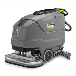
Description of the unit
1 Coarse dirt sieve 2 Fluff filter 3 Float 4 Cleaning head 5 Brush replacement pedal 6 Push handle 7 Safety button 8 Waste water tank cap 9 Homebase retaining rail 10 Waste water tank 11 ** Battery 12 Fresh water filter 13 Fresh water tank lock 14 Disc brush 15 Fresh water tank 16 Type plate 17 Hose switch 18 Fresh water tank filling hole 19 Suction bar 20 Suction bar height adjustment 21 Suction bar inclination adjustment 22 Wing nuts for fastening the suction bar 23 Suction hose 24 Fresh water filling level display Fresh water drain hose 25 Cleaning head lever 26 Water volume regulation knob 27 Suction bar lever 28 Battery plug connector 29 Key-operated switch 30 Display 31 Working speed rotary knob 32 Travel direction switch 33 Waste water tank drain hose with dosing unit 34 Transport holder for suction bars ** Not in scope of delivery
Color coding
Control elements for the cleaning process are yellow.
Control elements for maintenance and servicing are light gray.
Symbols on the device
Fresh water tank drain opening
Waste water tank drain opening
Increased cleaning head contact pressure
Battery access
Fresh water tank filling level (50%)
Insert the charger plug here
Eyelet point
* Mop holder
ATTENTION
Incorrect socket
Risk of damage
DO NOT insert the charger plug here
Normal cleaning head contact pressure
Raise the cleaning head
Pedal for raising/lowering the cleaning head
Brush replacement pedal
* optional
Installation
Unloading
Unloading
Remove the carton.
Remove the straps.
Remove the wooden blocks fastened to the pallet byscrews.
Put a ramp in front of the pallet using the 3 upper reinforcement boards from the carton packaging and the safety board screwed across the pallet and fasten with particle board screws.
Safety board
Squared timber
Reinforcement board
Push the squared timber unscrewed from the pallet under the ramp for support and screw tight.
Press the cleaning head lever downwards and engageit towards the right.
For BD 80/100 only: Press the brake lever down.
Note
There is no brake for BD 70/75. Releasing the brake is not necessary with this device.
Pull the device backwards off the pallet.
For BD 80/100 only: Press the brake lever up.
Installing the suction bar
Insert the suction bar in the suction bar mount
Tighten the wing nuts.
Fit the suction hose.
Batteries
Recommended battery sets BD 70/75
Description
Order no.
Volume (m3)*
Airflow (m3/ h)**
115 Ah - maintenance-free
2.815-091.0 1)
1.98
0.792
170 Ah - maintenance-free
2.815-092.0 2)
2.31
0.924
180 Ah - maintenance-free
2.815-101.0 3)
4.785
1.914
* Minimum volume of battery charging room
** Minimum air flow between battery charging room and environment
When installing for the first time, an additional battery installation set is required:
2.638-198.0
2.638-162.0
2.638-106.0
Recommended battery sets BD 80/100
Description
Order no.
Volume (m3)*
Airflow (m3/ h)**
170 Ah - maintenance-free
2.815-092.0 1)
2.31
0.924
180 Ah - maintenance-free
2.815-101.0 2)
4.785
1.914
240 Ah - maintenance-free
2.815-102.0 2)
6.27
2.508
285 Ah - maintenance-free
2.815-095.0 3)
11.88
4.752
* Minimum volume of battery charging room ** Minimum air flow between battery charging room and environment
When installing for the first time, an additional battery installation set is required:
2.638-162.0
2.638-106.0
2.638-197.0
Low-maintenance batteries (wet batteries)
DANGER
Refilling discharged batteries with water
Danger of acid burns from escaping acid, destruction of clothes
Wear safety goggles when handling the batteries.
Observe the applicable regulations.
Immediately rinse off any splashed acid from the skin or clothes using copious amounts of water.
ATTENTION
Using water with additives
Defective batteries, loss of warranty claim Top up the batteries using only distilled or desalinated water (EN 50272-T3).
Do not use any foreign additives, so-called enhancing agents, because this will invalidate the warranty.
Add distilled water one hour before the charging process comes to an end. Observe the correct acid level according to the battery label. All cells must produce gas at the end of the charging process.
Maintenance-free batteries (AGM and gel batteries)
ATTENTION
Risk of damage when opening AGM and gel batteries! AGM and gel batteries are maintenance-free and have a closed battery housing. Refilling them with distilled water or battery acid is not possible and is not necessary. Opening or drilling the battery housing will damage an AGM or gel battery and it will have to be replaced.
Do not open the battery housing and do not drill any holes. Do not cover the pressure relief valve and do not change it.
Only charge AGM and gel batteries using the specified chargers, see chapter: Charging the battery.
Installing and connecting batteries
CAUTION
Removing and installing the batteries
Unstable machine position
Ensure that the machine is positioned stably when removing and installing the batteries.
ATTENTION
Incorrect connection polarity
Destruction of the control electronics
Take care to ensure the correct polarity when connecting the batteries.
ATTENTION
Deep discharge
Risk of damage
Charge the batteries before starting the device.
1. Drain the waste water.
2. Pivot the waste water tank upwards.
3. Place the battery in the device as shown. Important: Push the batteries all the way back!
4. Insert a spacer between the right batteries and the fresh water tank, a for 115 Ah battery pack: 1 piece lengthwise, flat. b for battery packs other than 115 Ah: 2 pieces lengthwise upright on top of each other.
5. For BD 70/75 with battery pack 115 Ah: Insert the 4 additional weights.
6. Attach the battery fastener, to do so a. for BD 70/75: Install the 2 battery holders and for 115 Ah: Tighten at the left and middle threaded holes. For 170 Ah / 180 Ah: Tighten at the right and middle threaded holes. b. for BD 80/100: Insert one or two spacers flat lengthwise or vertically between the front batteries and the fresh water tank so that the batteries cannot slip forward.
7. Connect the battery terminals using the connection cables from the battery installation kit.
8. Clamp the connecting cable on the (+) and (-) battery terminals that are still free.
9. Connect the device-side battery connector to the battery-side battery connector.
10.Pivot the waste water tank downwards.
Removing the battery
CAUTION
Removing and installing the batteries
Unstable machine position
Ensure that the machine is positioned stably when removing and installing the batteries.
Turn the key-operated switch to "0" and remove the key.
Disconnect the battery connector.
Drain the waste water.
Pivot the waste water tank upwards.
Disconnect the device-end cable from the negative terminal at the battery.
Disconnect the remaining cables from the battery.
For BD 80/100: Remove the spacer(s) between the front batteries and the fresh water tank.
For 115 Ah battery pack: Take out the additional weights.
Remove the battery.
10.Dispose of the used batteries in accordance with statutory provisions.
Initial startup
Charging the battery
DANGER
Inappropriate use of the charger
Electric shock
Adhere to the mains voltage and fuse values specified on the device type plate.
Only use the charger in dry rooms with sufficient ventilation.
ATTENTION
Accumulation of dangerous gases under the tank during the charging process
Risk of explosion
Pivot the waste water tank upwards before charging lowmaintenance batteries.
ATTENTION
Using an unsuitable charger
Risk of damage
Do not connect the charger to the device-side battery connector.
Use only a charger suitable for the type of battery installed. Read the operating instructions of the charger manufacturer and observe the safety instructions in particular.
Battery set
Capacity
Charger
2.815-091.0
115 Ah
6.654-367.0
2.815-092.0
170 Ah
6.654-436.0
2.815-101.0
180 Ah
6.654-434.0
2.815-105.0
240 Ah
6.654-437.0
2.815-095.0
285 Ah
6.654-419.0
The average charging time is approx. 10-15 hours.
The device cannot be used during the charging process.
Note
The device has deep discharge protection, i.e. the brush motor and turbine are switched off automatically when the permitted minimum capacity level is reached.
Drive the device directly to the charger and do not driveon slopes.
Pull out the device-side battery connector. 1. Battery plug, device side 2. Battery plug, battery side
Connect the battery-side battery connector to the charger.
Plug the mains plug of the charger into the socket.
Carry out the charging process in accordance with theoperating instructions for the charger.
Connect the device-side battery connector to the battery-side battery connector.
Operation
Operation
ATTENTION
Risks during operation
Danger of injury
Release the safety button in the case of danger.
Filling with operating materials
Filling with fresh water
Open the fresh water tank lock.
Fill fresh water (max. 122 °F (50 °C)) to the lower edge of the fill-ing nozzle. Note: The fresh water hose can be clamped in the hose switch during filling.
Close the fresh water tank lock.
Notes on detergents
WARNING
Unsuitable detergents
Health risk, damage to the device
Use only recommended detergents. The operator carries all increased risks relating to operational safety and increased risk of accidents if using other detergents. Use only detergents free of solvents, salt and hydrofluoric acid.
Adhere to the safety instructions stated on the detergent packaging.
Note
Do not use heavily foaming detergent. Recommended detergents
Usage
Detergent
Maintenance cleaning of all water-resistant floors
RM 746
RM 780
Maintenance cleaning of polished hard surfaces (e.g. granite)
RM 755 es
Maintenance cleaning and basic cleaning of industrial floors
RM 69 ASF
Usage
Detergent
Maintenance cleaning and basic cleaning of fine stone tiles
RM 753
Maintenance cleaning of tiles in sanitary areas
RM 751
Cleaning and disinfection in sanitary areas
RM 732
Coating removal on all alkaline-resistant floors (e.g. PVC)
RM 752
Coating removal on linoleum floors
RM 754
Detergent
1. Fill the detergent into the fresh water tank. Note: The cap of the fresh water tank filling hole can be used for measuring the detergent. It is fitted with a scale on the inside.
Adjusting the water volume
1. Adjust the water volume via the regulating knob to suit the degree of contamination of the floor covering.
Note
Perform initial cleaning tests with a low water volume. Increase the water volume step by step until achieving the desired cleaning result.
Note
The cleaning head continues operating without a liquid supply if the fresh water tank is empty.
Adjusting the suction bar
Adjusting the inclination
The inclination must be adjusted so that the suction lips of the suction bar make even contact with the floor over the entire length of the suction bar.
Loosen the screw. 1 Screw
Adjust the inclination of the suction bar.
Tighten the screw.
Adjusting the height
The height adjustment affects the bending of the suction lips on contact with the floor.
Push the device a small distance forwards.
Compare the bending of the suction lips with the illustration below. 1 Spacer roller with holder 2 Washer 3 Screw
Unscrew the screw.
Position a sufficient number of washers between the suction bar and spacer roller so that the suction lips have the correct bend.
Fit the remaining washers above the spacer roller.
Screw in and tighten the screw.
Repeat the entire procedure at the other spacer roller.
Push the device a small distance forwards.
Check the bending of the suction lips over the entire length.
If necessary, repeat the entire adjustment process.
Switching the device on
1. Turn the key-operated switch to "1".
The display shows the following one after the other:
Period of time until the next after-sales Customer Service
Software version, control panel
Charging state of the battery and number of operating hours
Driving
Note
The travel direction can be changed during the cleaning operation. This way, a certain position can be intensively cleaned by driving back and forth several times.
1. Set the travel direction switch to "forward".
Note
To reduce vehicle width, the suction bar can be fastened to the transport holder. Narrow spaces can then be easily passed through.
Cleaning
Note
The inclination and height of the suction bar can be adjusted to improve the vacuuming results (see chapter Adjusting the suction bar).
Note
When the waste water tank is full, the float switch closes the suction opening and the suction turbine runs at a higher speed. In this case, raise the suction bar and drive to the location for emptying the waste water tank.
Turn the working speed rotary knob to the desired value.The speed is shown on the display during the adjustment. The display is shown in percentage of the maximum speed.
Set the water volume at the regulating valve.
Press the suction bar lever downwards.The suction bar lowers. Suctioning begins.
Press the cleaning head lever downwards, unlatch it and allow it to move upwards.
Pull the safety button towards the push handle.The cleaning head starts up and the device moves at the set speed.
Increasing the brush contact pressure
Let go of the safety button.
Lift the cleaning head lever up with your hand and engage it towards the right.
Finishing operation
Finishing cleaning
Let go of the safety button.
Press the cleaning head lever downwards and engageit towards the right.
Continue moving a short distance. The residual water is vacuumed up.
Lift the suction bar. The suctioning continues to run for 10 seconds afterwards.
Turn the key-operated switch to "0".
Charge the batteries if necessary.
Draining the wastewater
WARNING
Improper disposal of waste water
Environmental pollution
Observe the local waste water treatment regulations.
Remove the drain hose from the support and lower it over a suitable collecting device.
Press the dosing device together or kink the hose.
Open the dosing device cover.
Drain the waste water. Regulate the water volume by pressing or kinking.
Rinse the waste water tank with clear water.
Draining fresh water
1. Pull off the filling level display hose and swivel it down.
Draining fresh water quickly
Unscrew the fresh water tank lock.
Allow the fresh water to drain away.
Fit the fresh water tank lock and screw into place. Note: Ensure that the hose connection in the fresh water tank lock lies at the lowest point after screwing tight.
Care and service
DANGER
Inadvertently starting up device
Risk of injury, electric shock
Turn the key-operated switch to "0" and remove the key before performing any work on the device.
Pull out the charger mains plug.
Drain and dispose of the waste water and fresh water.
Safety inspection/maintenance contract
You can agree on regular safety inspections or close a maintenance contract with your dealer. Please seek advice on this.
Maintenance intervals
Each time after use
ATTENTION
Incorrect cleaning
Risk of damage.
Do not spray the device with water.
Do not use aggressive detergents.
A detailed description of the individual maintenance work is provided in Chapter Maintenance work.
Drain the waste water.
Rinse the waste water tank with clear water.
Clean the exterior of the device using a damp cloth, wetted with a mild washing lye.
Check the fluff filter and clean if required.
Clean the coarse dirt sieve.
Clean the suction lips, check for wear and tear and readjust or replace if necessary.
Check the disc brushes for wear and tear and replace if necessary.
Charge the battery.
If the charging state of the battery is below 50%, charge the battery fully and without interruption.
If the charging state of the battery is above 50%, only recharge the battery if the entire operating duration will be required when next used.
Weekly
l When used regularly, charge the battery fully and without interruption at least once a week.
Monthly
A detailed description of the individual maintenance work is provided in Chapter Maintenance work.
Drain the fresh water tank and flush out deposits.
Clean the fresh water filter.
Clean the float and fluff filter.
Check battery poles for oxidation, brush off if necessary. Make sure the connection cables are firmly in place.
Clean the seals between the waste water tank and the cover, check for leaks and replace if necessary.
Check the acid density of the cells if the batteries are not maintenance-free.
For a longer downtime, shut down the device when thebattery is fully charged. Fully charge the battery at least once a month.
Annually
l Have the prescribed inspection performed by Customer Service.
Maintenance work
Turn over or replace the worn suction lips
The suction lips must be turned over or replace when they have worn down to the wear mark.
1. Wear mark
2. Suction lip
Remove the suction bar.
Unscrew the star handles.
Pull off the plastic parts.
Pull off the suction lips.
Push in the turned over or new suction lips.
Push on the plastic parts.
Screw in and tighten the star handles.
Cleaning the coarse dirt sieve
Open the waste water tank cover 1. Coarse dirt sieve
Pull the coarse dirt sieve upwards and off.
Rinse off the coarse dirt sieve under running water.
Reinsert the coarse dirt sieve into the waste water tank.
Cleaning the fresh water filter
Drain the fresh water (see Chapter Draining fresh water).
Unscrew the fresh water tank lock. 1 Fresh water tank lock 2 Fresh water filter
Pull out the fresh water filter and rinse with clean water.
Insert the fresh water filter.
Fit the fresh water tank lock.
Note: Ensure that the hose connection in the fresh water tank lock lies at the lowest point after screwing tight.
Clean the float and fluff filter
Open the waste water tank cover. 1 Latching hooks 2 Float 3 Fluff filter 4 Float housing
Release the latching hooks.
Pull the float housing downwards and off.
Remove the float from the float housing and clean it.
Remove the fluff filter and clean it.
Assemble all parts in the reverse order.
Replacing the disc brushes
Raise the cleaning head.
Press the brush replacement pedal down, beyond the zone of resistance.
Pull the 1st disc brush sideways and out from underneath the cleaning head.
Hold the new disc brush under the cleaning head, thenpress upwards and latch it into position.
Repeat the procedure for the 2nd disc brush.
Troubleshooting guide
Malfunction
Rectification
The device cannot be started
Turn the key-operated switch to "1".
Actuate the safety button.
Insert the battery plug.
Check the battery and charge if necessary.
Check that the battery terminals are correctly connected.
The water volume is insufficient
Check the fresh water filling level and fill the tank if necessary.
Increase the water volume at the water volume regulating knob.
Clean the fresh water filter.
Check the hoses for clogging and clean if necessary.
The suction performance is too low
Shut down the device and drain the waste water.
Clean the seals between the waste water tank and the cover, check for leaks and replaceif necessary.
Check that the suction hose is correctly connected to the waste water tank.
Check the fluff filter for contamination and clean if necessary.
Clean the suction lips at the suction bar, turn over or replace if necessary.
Check that the cap on the waste water drain hose is closed.
Check the adjustment of the suction bar.
Check the suction hose for clogging and clean if necessary. When fitting the suction hose again, the white marking on the hose must lie at the retaining clip.
Check the suction hose for leaks and replace if necessary.
The cleaning results are unsatisfactory
Reduce the driving speed.
Check the brushes for wear and tear and replace if necessary.
Check the suitability of the brush type and detergent used.
The suction turbine runs at an increased speed
Drain the waste water.
Clean the float.
Check the fluff filter and clean if necessary.
Check the suction hose for clogging and clean if necessary.
Check the suction bar for clogging and remove any clogging if necessary
The brushes do not rotate
1. Check if the brushes are blocked by a foreign body and remove the foreign body if necessary.

 The packing materials can be recycled. Please dispose of packaging in accordance with the environmental regulations.
 Electrical and electronic appliances contain valuable, recyclable materials and often components such as batteries, rechargeable batteries or oil, which - if handled or disposed of incorrectly - can pose a potential threat to human health and the environment. However, these components are required for the correct operation of the appliance. Appliances marked by this symbol are not allowed to be disposed of together with the household rubbish.
 Fresh water tank drain opening
 Waste water tank drain opening
 Increased cleaning head contact pressure
 Battery access
 Fresh water tank filling level (50%)
 Insert the charger plug here
 Eyelet point
 * Mop holder
 ATTENTION
 Normal cleaning head contact pressure
 Raise the cleaning head
 Pedal for raising/lowering the cleaning head
 Brush replacement pedal