
HT-IS100
Operating Instructions
©2008 Sony Corporation
3-299-270-21(2)
Home Theatre
System
2
GB
3
To reduce the risk of fire or electric
shock, do not expose this apparatus to
rain or moisture.
Batteries or batteries installed apparatus shall not be
exposed to excessive heat such as sunshine, fire or the
like.
Do not install the appliance in a confined space, such as
a bookcase or built-in cabinet.
To prevent fire, do not cover the ventilation of the
apparatus with news papers, table-cloths, curtains, etc.
And don’t place lighted candles on the apparatus.
To prevent fire or shock hazard, do not place objects
filled with liquids, such as vases, on the apparatus.
In door use only.
Disposal of Old Electrical
& Electronic Equipment
(Applicable in the
European Union and
other European
countries with separate
collection systems)
This symbol on the product or
on its packaging indicates that
this product shall not be treated as household
waste. Instead it shall be handed over to the
applicable collection point for the recycling of
electrical and electronic equipment. By ensuring
this product is disposed of correctly, you will
help prevent potential negative consequences for
the environment and human health, which could
otherwise be caused by inappropriate waste
handling of this product. The recycling of
materials will help to conserve natural resources.
For more detailed information about recycling of
this product, please contact your local Civic
Office, your household waste disposal service or
the shop where you purchased the product.
Disposal of waste
batteries (applicable in
the European Union and
other European
countries with separate
collection systems)
This symbol on the battery or on the packaging
indicates that the battery provided with this
product shall not be treated as household waste.
By ensuring these batteries are disposed of
correctly, you will help prevent potentially
negative consequences for the environment and
human health which could otherwise be caused
by inappropriate waste handling of the battery.
The recycling of the materials will help to
conserve natural resources. In case of products
that for safety, performance or data integrity
reasons require a permanent connection with an
incorporated battery, this battery should be
replaced by qualified service staff only. To
ensure that the battery will be treated properly,
hand over the product at end-of-life to the
applicable collection point for the recycling of
electrical and electronic equipment. For all other
batteries, please view the section on how to
remove the battery from the product safely. Hand
the battery over to the applicable collection point
for the recycling of waste batteries. For more
detailed information about recycling of this
product or battery, please contact your local
Civic Office, your household waste disposal
service or the shop where you purchased the
product.
FOR THE CUSTOMERS IN EUROPE
The manufacturer of this product is Sony Corporation,
1-7-1 Konan Minato-ku Tokyo, 108-0075 Japan. The
Authorized Representative for EMC and product safety
is Sony Deutschland GmbH, Hedelfinger Strasse 61,
70327 Stuttgart, Germany. For any service or guarantee
matters please refer to the addresses given in separate
service or guarantee documents.
WARNING

3
GB
Copyrights
This system incorporates Dolby* Digital and Pro Logic
Surround and the DTS** Digital Surround System.
* Manufactured under license from Dolby
Laboratories.
“Dolby”, “Pro Logic”, and the double-D symbol are
trademarks of Dolby Laboratories.
** Manufactured under license under U.S. Patent #'s:
5,451,942; 5,956,674; 5,974,380; 5,978,762;
6,487,535 & other U.S. and worldwide patents
issued & pending. DTS and DTS Digital Surround
are registered trademarks and the DTS logos and
Symbol are trademarks of DTS, Inc. © 1996-2007
DTS, Inc. All Rights Reserved.
This system incorporates High-Definition Multimedia
Interface (HDMI™) technology.
HDMI, the HDMI logo and High-Definition
Multimedia Interface are trademarks or registered
trademarks of HDMI Licensing LLC.
“BRAVIA” is a trademark of Sony Corporation.
“S-AIR” and its logo are trademarks of Sony
Corporation.
On safety
• Should any solid object or liquid fall into the system,
unplug the system and have it checked by qualified
personnel before operating it any further.
• Do not climb on the subwoofer, as you may fall down
and injure yourself, or system damage may result.
On power sources
• Before operating the system, check that the operating
voltage is identical to your local power supply. The
operating voltage is indicated on the nameplate at the
rear of the subwoofer.
• If you are not going to use the system for a long time,
be sure to disconnect the system from the wall outlet
(mains). To disconnect the AC power cord (mains
lead), grasp the plug itself; never pull the cord.
• One blade of the plug is wider than the other for the
purpose of safety and will fit into the wall outlet
(mains) only one way. If you are unable to insert the
plug fully into the outlet, contact your dealer.
• AC power cord (mains lead) must be changed only at
the qualified service shop.
• The system is not disconnected from the AC power
source (mains) as long as it is connected to the wall
outlet, even if the system itself has been turned off.
• Install this system so that the power cord can be
unplugged from the wall socket immediately in the
event of trouble.
On heat buildup
Although the system heats up during operation, this is
not a malfunction. If you continuously use this system
at a large volume, the system temperature of the back
and bottom rises considerably. To avoid burning
yourself, do not touch the system.
On placement
• Place the system in a location with adequate
ventilation to prevent heat buildup and prolong the
life of the system.
• Do not place the system near heat sources, or in a
place subject to direct sunlight, excessive dust, or
mechanical shock.
• Do not place anything at the rear of the subwoofer
that might block the ventilation holes and cause
malfunctions.
• Do not place the system near equipment such as a TV,
VCR, or tape deck. (If the system is being used in
combination with a TV, VCR, or tape deck, and is
placed too close to that equipment, noise may result,
Precautions
continued

4
GB
and picture quality may suffer. This is especially
likely when using an indoor antenna. Therefore, we
recommend using an outdoor antenna.)
• Use caution when placing the system on surfaces that
have been specially treated (with wax, oil, polish, etc.)
as staining or discoloration of the surface may result.
On operation
Before connecting other components, be sure to turn off
and unplug the system.
If you encounter color irregularity on
a nearby TV screen
The system is magnetically shielded to allow it to be
installed near a TV set. However, color irregularities
may still be observed on certain types of TV sets.
If color irregularity is observed...
Turn off the TV set, then turn it on again after 15 to 30
minutes.
If color irregularity is observed
again...
Place the system further away from the TV set.
On cleaning
Clean the system with a soft dry cloth. Do not use any
type of abrasive pad, scouring powder or solvent such
as alcohol or benzine.
If you have any question or problem concerning your
system, please consult your nearest Sony dealer.

5
GB
Precautions...............................................3
Getting Started
Supplied Accessories ...............................6
Step 1: Positioning the Speakers..............7
Step 2: Connecting the Speakers............15
Step 3a: Connecting the Components with
HDMI Jacks.....................................16
Step 3b: Connecting the Components
without HDMI Jacks........................18
Step 4: Connecting the Antenna (Aerial)
.........................................................22
Step 5: Connecting the AC Power Cord
(Mains Lead)....................................24
Step 6: Calibrating the Appropriate
Settings Automatically ....................24
(Auto Calibration)
Setting up the Sound Output of the
Connected Component ....................28
Function for Conversion of Video Signals
.........................................................29
Connecting the Other Components........30
Playback Options
Index to Parts and Controls....................32
Enjoying TV...........................................35
Enjoying Other Components..................36
Surround Functions
Enjoying the Surround Effects...............38
Adjusting the Bass, Middle, and Treble
Level ................................................40
Enjoying the Movies at Night................40
“BRAVIA” Sync features
What is “BRAVIA” Sync?.....................41
Preparing for the “BRAVIA” Sync........41
Enjoying a Blu-ray Disc/DVD...............43
(One-Touch Play)
Enjoying the TV sound from the Speakers
.........................................................43
(System Audio Control)
Turning off the TV, System, and
Connected Components...................45
(System Power Off)
Tuner Functions
Presetting Radio Stations ...................... 46
Listening to the Radio ........................... 47
Using the Radio Data System (RDS) .... 49
Advanced Settings
Controlling the Connected Sony
Components with the Remote......... 50
Changing the Input Button Assignments of
the Remote ...................................... 53
Settings and Adjustments Using the
Amplifier Menu .............................. 54
Reassigning the audio inputs................. 63
Using an S-AIR Product........................ 65
Using the IR repeater............................. 72
Additional Information
Troubleshooting .................................... 73
Specifications ........................................ 76
Glossary................................................. 77
Index...................................................... 79
Table of Contents
6
GB
Please check the following accessories in the
package.
Remote commander (RM-AAU035) (1)
Size AA (R6) batteries (2)
Optical cable (2.5 m) (1)
FM wire antenna (aerial) (1)
AM loop antenna (aerial) (1)
Calibration mic (1)
Speaker (with Remote commander
receiver) (1)
Speakers (4)
Extra speaker pedestal (1)
Brackets (5)
Wrench (1)
Screw (+PSW4 × 12) (1)
Operating Instructions (1)
Quick Start Guide (card) (1)
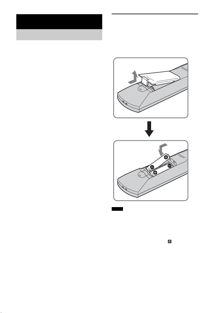
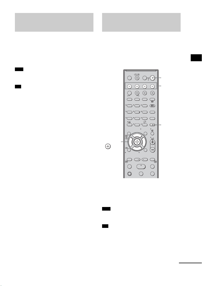
Inserting batteries into the
remote
You can control the system using the supplied
remote. Insert two size AA (R6) batteries by
matching the + and – ends on the batteries to the
markings inside the compartment.
• Do not leave the remote in an extremely hot or humid
place.
• Do not use a new battery with an old one.
• Do not drop any foreign object into the remote casing,
particularly when replacing the batteries.
• Do not expose the remote sensor ( ) to direct light
from the sun or lighting apparatus. Doing so may
cause a malfunction.
• If you do not intend to use the remote for an extended
period of time, remove the batteries to avoid possible
damage from battery leakage and corrosion.
Getting Started
Supplied Accessories
Notes
7
GB
Getting Started
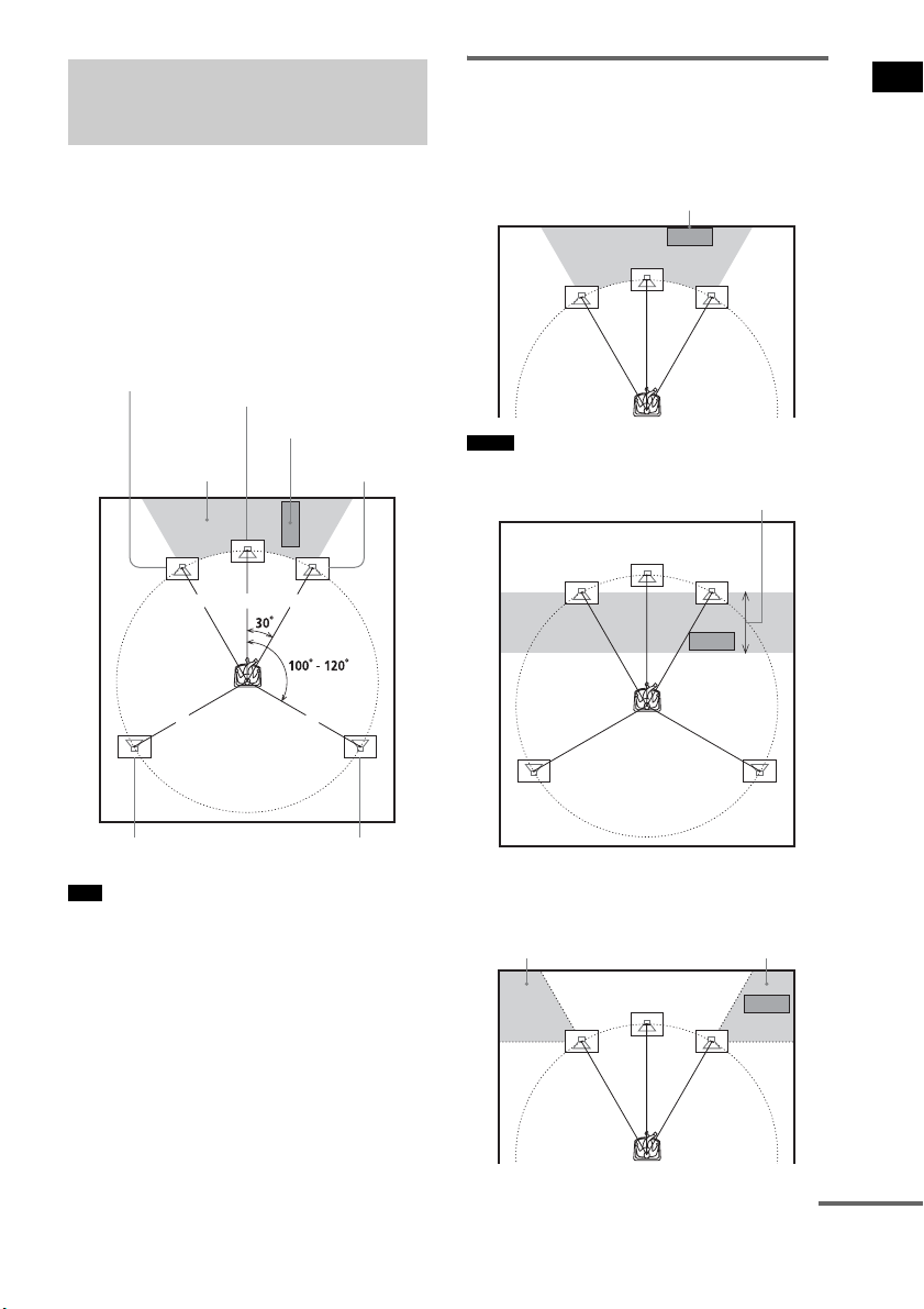
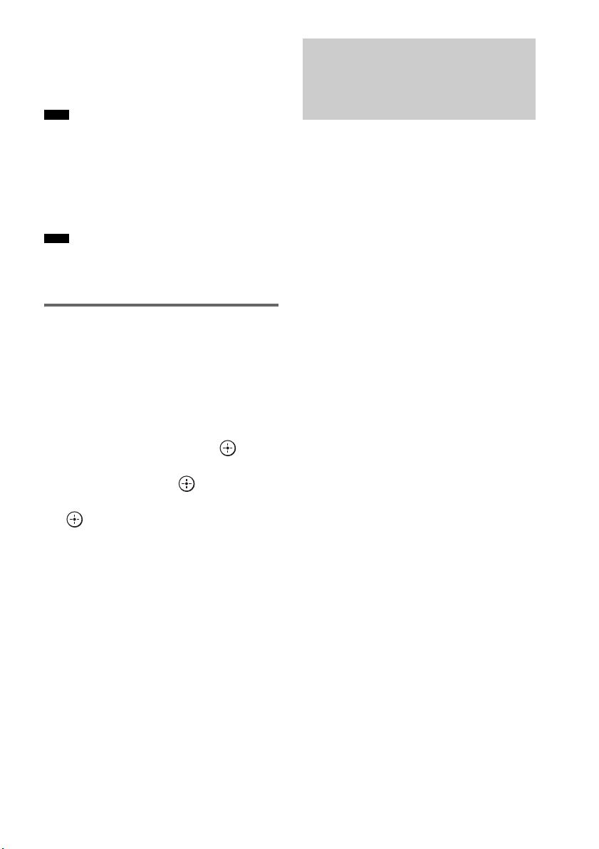
For the best possible surround sound, all the
speakers other than the subwoofer should be
placed at the same distance from the listening
position (1). Sony recommends that the
subwoofer should be placed (2).
Place speakers and subwoofer as illustrated
below.
• You can also place the subwoofer either side, facing
the listening position.
• When you install the speaker, the speaker face may be
unstable. In this case, use a commercially available
wire clamper or a commercially available tape, etc., to
secure the speaker cord.
Using the subwoofer
efficiently
To reinforce the bass sound, place the subwoofer
possible close to a wall.
• If the subwoofer is to be placed ahead of the front
speaker, the distance should be less than 0.5 m.*
• You may not get the bass sound efficiently when the
subwoofer is placed outside (3). You need to adjust
the setting of the distance from the listening position.
Step 1: Positioning the
Speakers
Tips
1 1 1
11
2
Subwoofer
Center speaker
Front right speaker
Front left speaker
Surround left speaker Surround right speaker
Notes
Close to a wall
*
33
continued

8
GB
• Do not place objects on the top of the subwoofer
where the speaker unit is installed.
• Do not place the subwoofer under a desk or in a
cabinet, etc.
• Do not place the subwoofer back of the obstruction,
such as TV, etc. Middle range sound will fall.
• Do not set the speakers in an inclined position.
• Do not place the speakers in locations that are:
– Extremely hot or cold
– Dusty or dirty
– Very humid
– Subject to vibrations
– Subject to direct sunlight
• Use caution when placing the speakers and/or speaker
stands (not supplied) that are attached with the
speakers on a specially treated (waxed, oiled,
polished, etc.) floor, as staining or discoloration may
result.
• When cleaning, use a soft cloth such as a cleaning
cloth for glasses.
• Do not use any type of abrasive pad, scouring powder,
or solvent such as alcohol or benzine.
• Image distortion on the TV screen may occur
depending on the location of the subwoofer. In this
case, place the subwoofer away from the TV.
• When you change the positions of the speakers, Sony
recommends that you change the settings. For details,
see “Step 6: Calibrating the Appropriate Settings
Automatically” (page 24).
Notes
Tip
TV, etc.
9
GB
Getting Started
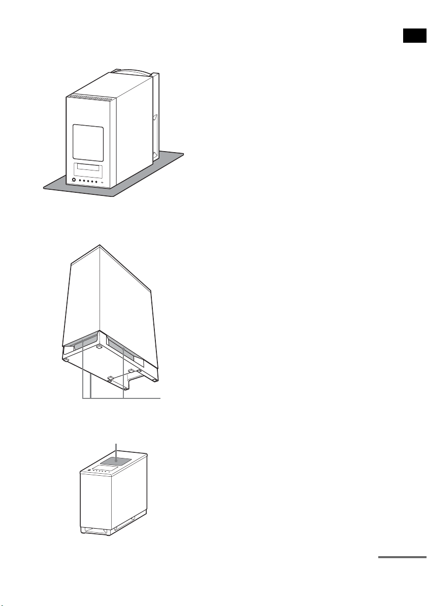
Notes on handling the subwoofer
• Place a soft cloth under the subwoofer when you lay
the subwoofer down for connection.
• Do not place your hand into the slit of the subwoofer
when lifting it. The speaker driver may be damaged.
When lifting, hold the bottom of the subwoofer.
• Do not push the top of the subwoofer where the
speaker unit is installed.
Slits
Speaker unit
continued
10
GB
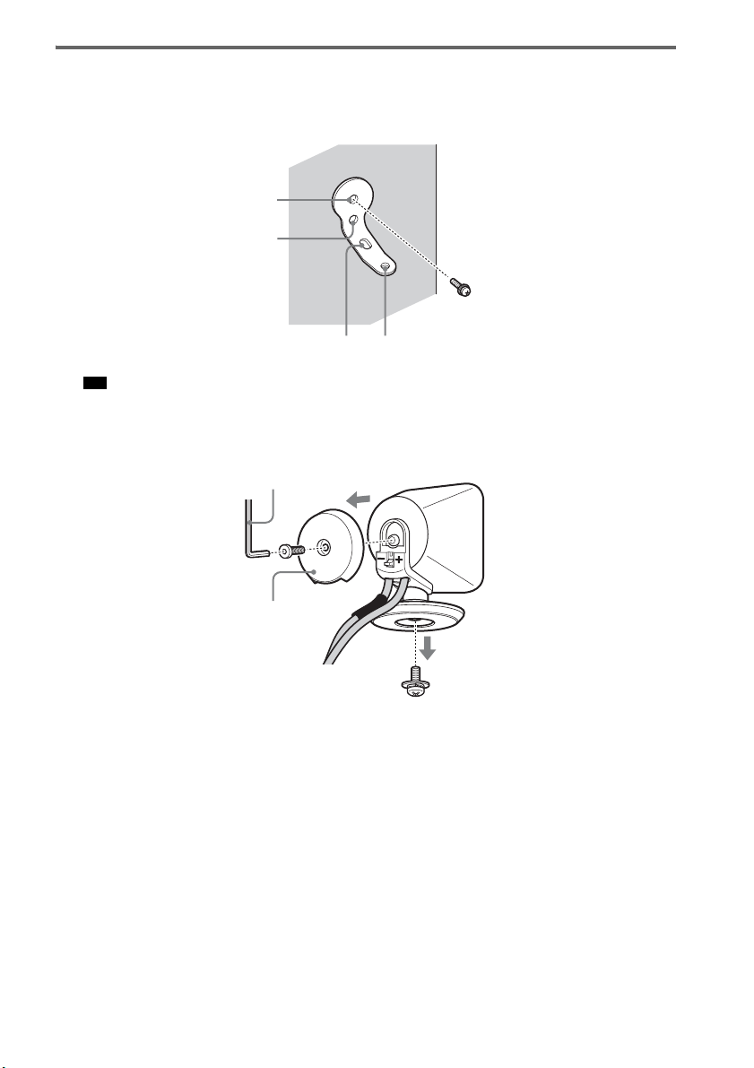
Installing the speakers on a wall
1 Prepare screws (not supplied) that are suitable for the holes of the bracket.
2 Secure the bracket to the wall using hole 1.
• To prevent the speaker from rotating, use the hole 2, too.
3 Remove the rear cap using the wrench (supplied), and remove the speaker pedestal
using a screwdriver (+) (not supplied).
Tip
1
34
2
Rear cap
Wrench (supplied)
11
GB
Getting Started
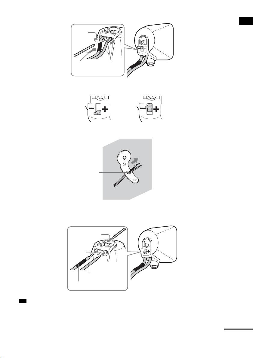
4 Push A with the supplied wrench (1), and then remove the speaker cords (2).
5 Thread the speaker cords through hole 3.
6 Reconnect the detached speaker cords, matching 3/# to the appropriate speaker
terminals (1), and then push the lever down completely (2).
• If it is difficult to push the lever down, use the wrench (supplied).
Tip
(1)
When the lever is down, the
speaker cords are locked.
When the lever is up, the
speaker cords can be removed.
(2)
A
3
#
3
(1)
(2)
continued
12
GB
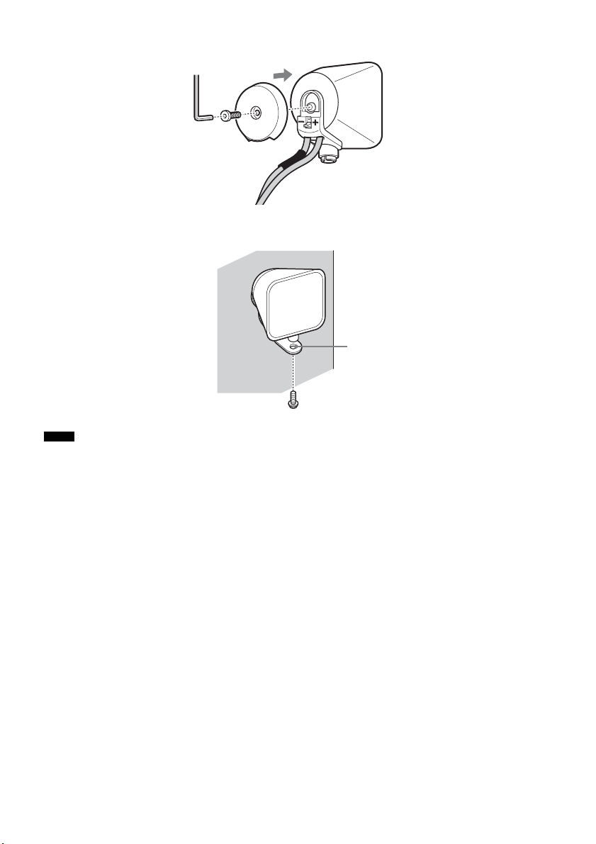
7 Reattach the rear cap using the wrench (supplied).
8 Secure the speaker to the bracket with the screw in step 3 using hole 4.
• Use screws that are suitable for the wall material and strength. As a plaster board wall is especially fragile, attach
the screws securely to a beam and fasten them to the wall. Install the speakers on a vertical and flat wall where
reinforcement is applied.
• Contact a screw shop or installer regarding the wall material or screws to be used.
• Sony is not responsible for accident or damage caused by improper installation, insufficient wall strength or
improper screw installation, natural calamity, etc.
Notes
4
13
GB
Getting Started
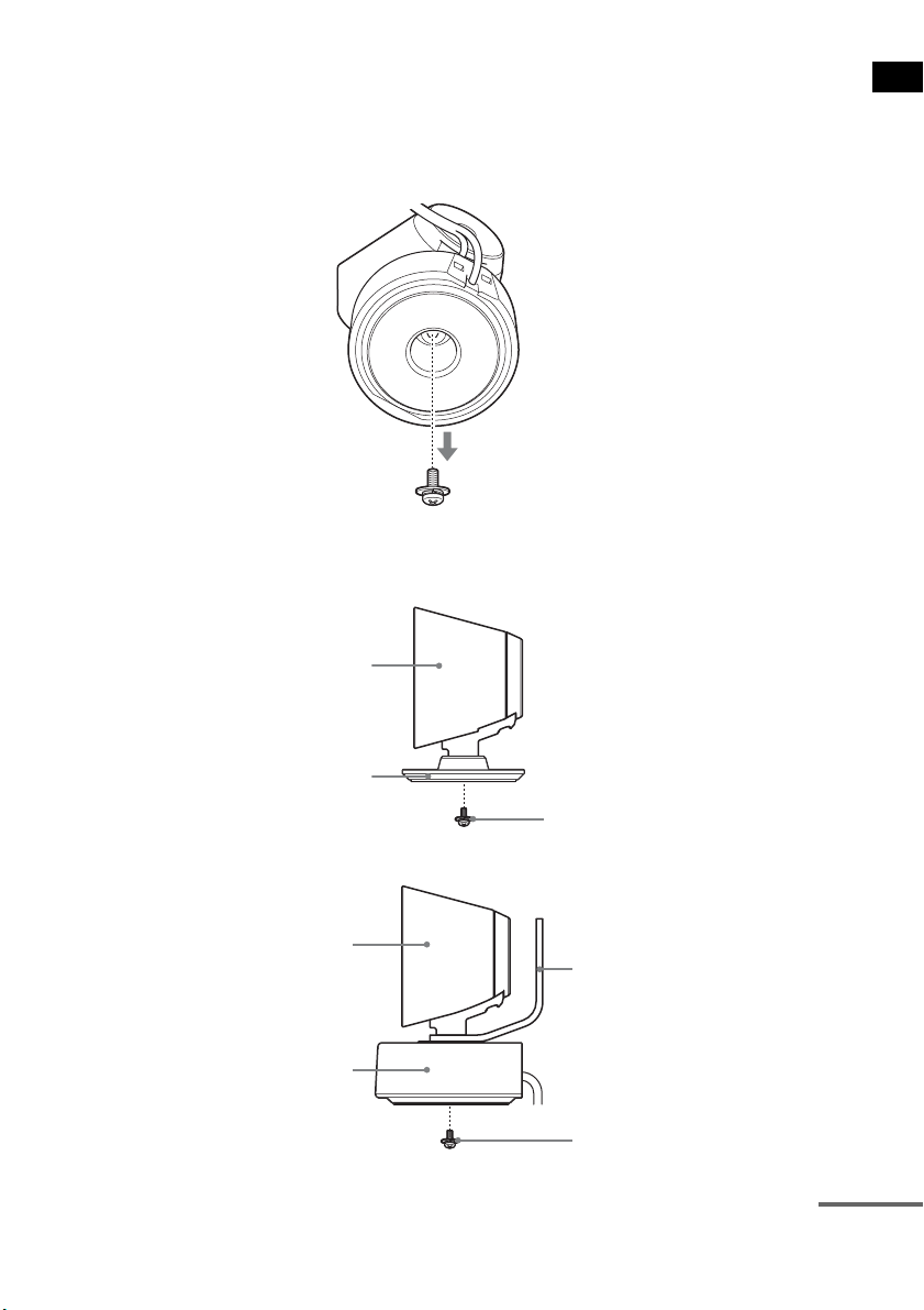
About the center speaker
You can remove the remote commander receiver from the center speaker, allowing them to be used
separately.
You can also install the remote commander receiver with the center speaker on a wall.
1 Remove the remote commander receiver using a screwdriver (+) (not supplied).
2 Secure the speaker with the screw.
To use the center speaker and remote commander receiver separately.
To install the remote commander receiver on a wall.
Center speaker
Extra speaker pedestal
(supplied)
Screw in step 1
Center speaker
Remote commander receiver
Bracket
Screw (+PSW4 × 12) (supplied)
continued
14
GB
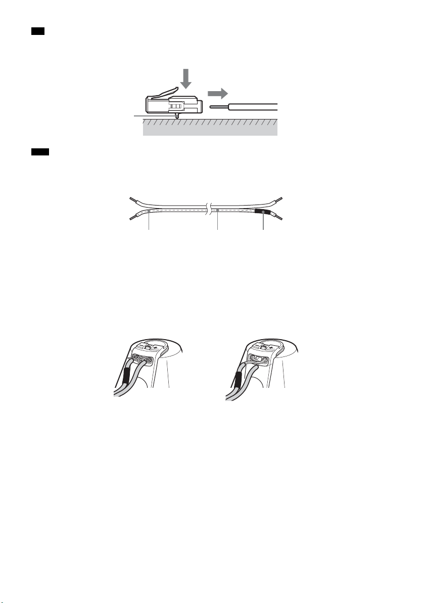
• You can remove the speaker cords from the connector. With the catch facing down, press and hold the connector
down against a flat surface (1) and remove the speaker cords from the connector (2).
• When you reconnect the speaker cords to the connector, be sure to match the speaker cords to the appropriate
speaker terminals: 3 to +, and # to –. Connect the cord with white letters or lines (to which a black tube is also
attached on one side) to –. If the cords are reversed, the sound will lack bass and may be distorted.
To avoid short-circuiting the speakers
Short-circuiting of the speakers may damage the system. To prevent this, be sure to follow these
precautions when connecting the speakers. Make sure the bare wire of each speaker cord does not touch
another speaker terminal or the bare wire of another speaker cord, such as shown below.
Tip
Note
Catch
(1)
(2)
#
White letters or lines Black tube
Stripped speaker cord is
touching another speaker
terminal.
Stripped cords are touching each
other due to excessive removal of
insulation.
15
GB
Getting Started
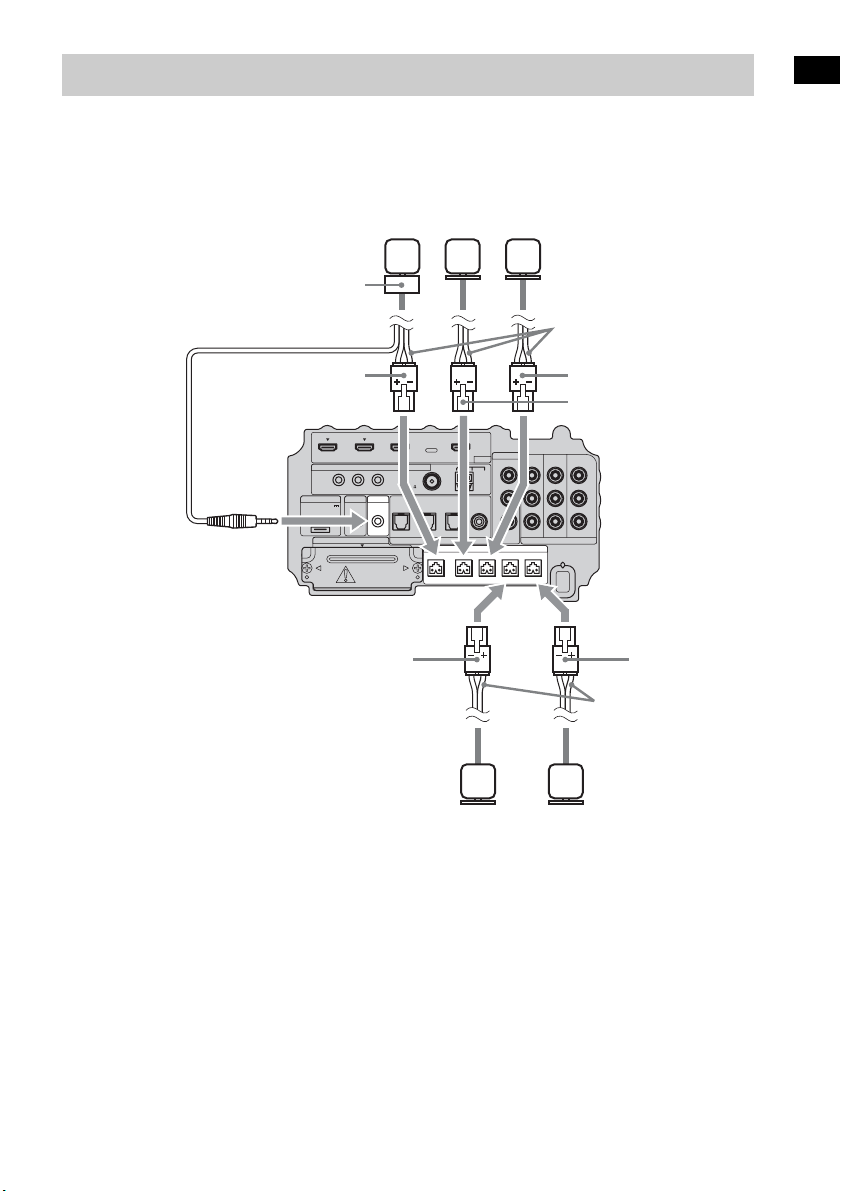
Connect the connectors of the speaker cords to their corresponding SPEAKER jacks. The connectors
of the speaker cords are the same color as the jacks to be connected.
Connect the cord of the remote commander receiver to the IR-R100 jack.
Step 2: Connecting the Speakers
IR REMOTE
VIDEO
DMPORT
SPEAKER ONLY FOR SS-IS15
ECM-AC2 IR-R100
ANTENNA
HDMI
IR IN IR OUT1 IR OUT2
FM AM
75
COAXIAL
DC 5V
0.7A MAX
FRONT R FRONT L SUR R SUR LCENTER
BD IN DVD IN SAT IN
SAT IN
ASSIGNABLE
COAXIAL
AUDI O IN
ASSIGNABLE
VIDEO IN
L
R
TV OUT
EZW-T100 DIGITAL
TV IN DVD IN SAT IN
OPTICAL
COMPONENT VIDEO
DVD IN SAT IN
MONITOR
OUT
Y
P
B/
C
B
PR/
C
R
Speaker cords
Bottom of the
subwoofer
Center
speaker
Front right
speaker
Front left
speaker
Speaker cords
Surround
left speaker
Surround
right speaker
Green
Red
White
Gray
Blue
Remote commander
receiver
16
GB
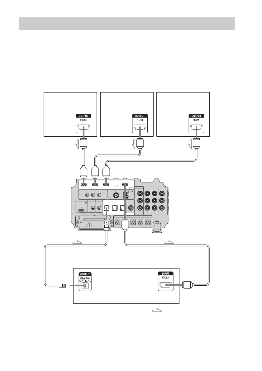
Sony recommends that you connect components to the system using an HDMI cable.
With HDMI, you can easily enjoy both high quality sound and high quality images.
However, it is necessary to connect the audio output of the TV to the audio input of the system
using an optical cable in order to listen to the TV’s sound from the system.
For details on the Control for HDMI function, see ““BRAVIA” Sync features” (page 41).
Step 3a: Connecting the Components with HDMI Jacks
IR REMOTE
VIDEO
DMPORT
SPEAKER ONLY FOR SS-IS15
ECM-AC2 IR-R100
ANTENNA
HDMI
IR IN IR OUT1 IR OUT2
FM AM
75
COAXIAL
DC 5V
0.7A MAX
FRONT R FRONT L SUR R SUR LCENTER
BD IN DVD IN SAT IN
SAT IN
ASSIGNABLE
COAXIAL
AUDI O IN
ASSIGNABLE
VIDEO IN
L
R
TV OUT
EZW-T100 DIGITAL
TV IN DVD IN SAT IN
OPTICAL
COMPONENT VIDEO
DVD IN SAT IN
MONITOR
OUT
Y
P
B/
C
B
PR/
C
R
TV monitor, projector, etc.
A HDMI cable (not supplied)
B Optical cable (supplied)
Blu-ray Disc player (recorder),
“PlayStation 3”
Audio/video
signal
Satellite tuner
Audio/video
signal
B
A
Audio/video
signal
DVD player (recorder)
Audio signal
: Signal flow
A
A
A
Bottom of the
subwoofer
Audio/video
signal

17
GB
Getting Started
• For details on connecting to components without HDMI jacks, see page 18.
• The HDMI jack has priority when you connect the component to the system using the HDMI input jacks and other
input jacks at the same time.
Notes on HDMI connections
• You can enjoy high quality images using an HDMI cable with an HDMI logo. Sony recommends that
you use a Sony HDMI cable.
• Check the setup of the connected component if an image is poor or the sound does not come out of a
component connected via the HDMI cable.
• Audio signals (sampling frequency, bit length, etc.) transmitted from an HDMI jack may be
suppressed by the connected component.
• Sound may be interrupted when the sampling frequency or the number of channels of audio output
signals from the playback component is switched.
• When the connected component is not compatible with copyright protection technology (HDCP), the
image and/or the sound from the HDMI TV OUT jack may be distorted or may be not output.
In this case, check the specification of the connected component.
• Sony does not recommend using an HDMI-DVI conversion cable.
• Regardless of which input is selected for the system, video signals from the input jack selected the
last time are output from the HDMI TV OUT jack.
Notes

18
GB
When you connect a DVD player (recorder), satellite tuner, VCR, etc., that has no HDMI jacks, you
can choose the connecting combination of the system. This subwoofer is equipped with a function for
converting video signals. For details, see “Function for Conversion of Video Signals” (page 29).
Connecting a TV monitor
The image from a visual component connected to this subwoofer can be displayed on a TV monitor,
projector, etc.
• Connect image display components such as a TV or a projector to the MONITOR OUT jacks on the subwoofer.
• Be sure to turn on the subwoofer when the video and audio of a playback component are being output to a TV via
the subwoofer. If the power supply of the subwoofer is not turned on, neither video nor audio signal is transmitted.
• You can reassign the analog audio input using the AUDIO IN ASSIGNABLE jacks. For details, see “Reassigning
the analog audio input” (page 63).
• You can watch the selected input image when you connect the MONITOR OUT jack to a TV.
Step 3b: Connecting the Components without HDMI Jacks
Notes
Tips
IR REMOTE
VIDEO
DMPORT
SPEAKER ONLY FOR SS-IS15
ECM-AC2 IR-R100
ANTENNA
HDMI
IR IN IR OUT1 IR OUT2
FM AM
75
COAXIAL
DC 5V
0.7A MAX
FRONT R FRONT L SUR R SUR LCENTER
BD IN DVD IN SAT IN
SAT IN
ASSIGNABLE
COAXIAL
AUDI O IN
ASSIGNABLE
VIDEO IN
L
R
TV OUT
EZW-T100 DIGITAL
TV IN DVD IN SAT IN
OPTICAL
COMPONENT VIDEO
DVD IN SAT IN
MONITOR
OUT
Y
P
B/
C
B
PR/
C
R
INPUT
TV monitor, projector, etc.
A
A Optical cable (supplied)
B Audio cord (not supplied)
C Component video cord (not supplied)
Video signal
: Signal flow
B
Audio signal
Bottom of the
subwoofer
C
or
19
GB
Getting Started
• To output the TV sound from the speakers connected to the subwoofer, be sure to
– connect the audio output jacks of the TV to the OPTICAL TV IN jacks of the subwoofer.
– turn off or mute the TV’s volume.
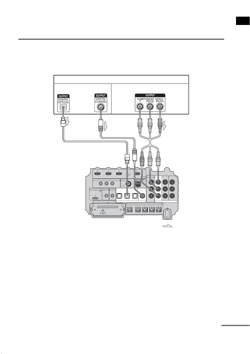
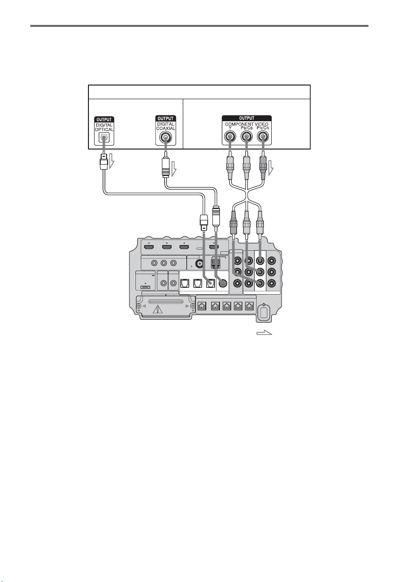
Connecting a DVD player (recorder)
The following illustration shows how to connect a DVD player (recorder).
You can reassign the digital audio input using the ASSIGNABLE COAXIAL SAT IN jack. For details,
see “Reassigning the digital audio input” (page 64).
IR REMOTE
VIDEO
DMPORT
SPEAKER ONLY FOR SS-IS15
ECM-AC2 IR-R100
ANTENNA
HDMI
IR IN IR OUT1 IR OUT2
FM AM
75
COAXIAL
DC 5V
0.7A MAX
FRONT R FRONT L SUR R SUR LCENTER
BD IN DVD IN SAT IN
AUDI O IN
ASSIGNABLE
VIDEO IN
L
R
TV OUT
EZW-T100 DIGITAL
TV IN DVD IN SAT IN
OPTICAL
COMPONENT VIDEO
DVD IN SAT IN
MONITOR
OUT
Y
P
B/
C
B
PR/
C
R
SAT IN
ASSIGNABLE
COAXIAL
DVD player (recorder)
A
A Optical cable (not supplied)
B Coaxial cord (not supplied)
C Component video cord (not supplied)
Video signal
: Signal flow
B
Audio signal
Bottom of the
subwoofer
or
C
continued
20
GB
Connecting a satellite tuner
The following illustration shows how to connect a satellite tuner.
If the satellite tuner does not have an OPTICAL OUT jack, connect the system using the COAXIAL
SAT IN jack.
IR REMOTE
VIDEO
DMPORT
SPEAKER ONLY FOR SS-IS15
ECM-AC2 IR-R100
ANTENNA
HDMI
IR IN IR OUT1 IR OUT2
FM AM
75
COAXIAL
DC 5V
0.7A MAX
FRONT R FRONT L SUR R SUR LCENTER
BD IN DVD IN SAT IN
AUDI O IN
ASSIGNABLE
VIDEO IN
L
R
TV OUT
EZW-T100 DIGITAL
TV IN DVD IN SAT IN
OPTICAL
COMPONENT VIDEO
DVD IN SAT IN
MONITOR
OUT
Y
P
B/
C
B
PR/
C
R
SAT IN
ASSIGNABLE
COAXIAL
Satellite tuner
C
A Optical cable (not supplied)
B Coaxial cord (not supplied)
C Component video cord (not supplied)
Video signal
: Signal flow
B
Audio signal
or
A
Bottom of the
subwoofer
21
GB
Getting Started
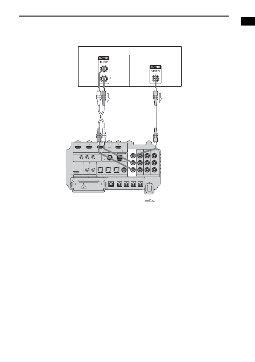
Connecting a VCR
The following illustration shows how to connect a component which has analog jacks such as a VCR,
etc.
IR REMOTE
VIDEO
DMPORT
SPEAKER ONLY FOR SS-IS15
ECM-AC2 IR-R100
ANTENNA
HDMI
IR IN IR OUT1 IR OUT2
FM AM
75
COAXIAL
DC 5V
0.7A MAX
FRONT R FRONT L SUR R SUR LCENTER
BD IN DVD IN SAT IN
AUDI O IN
ASSIGNABLE
VIDEO IN
L
R
TV OUT
EZW-T100 DIGITAL
TV IN DVD IN SAT IN
OPTICAL
COMPONENT VIDEO
DVD IN SAT IN
MONITOR
OUT
Y
P
B/
C
B
PR/
C
R
SAT IN
ASSIGNABLE
COAXIAL
VCR
A
A Audio cord (not supplied)
B Video cord (not supplied)
Video signal
: Signal flow
B
Audio
signal
Bottom of the
subwoofer
22
GB
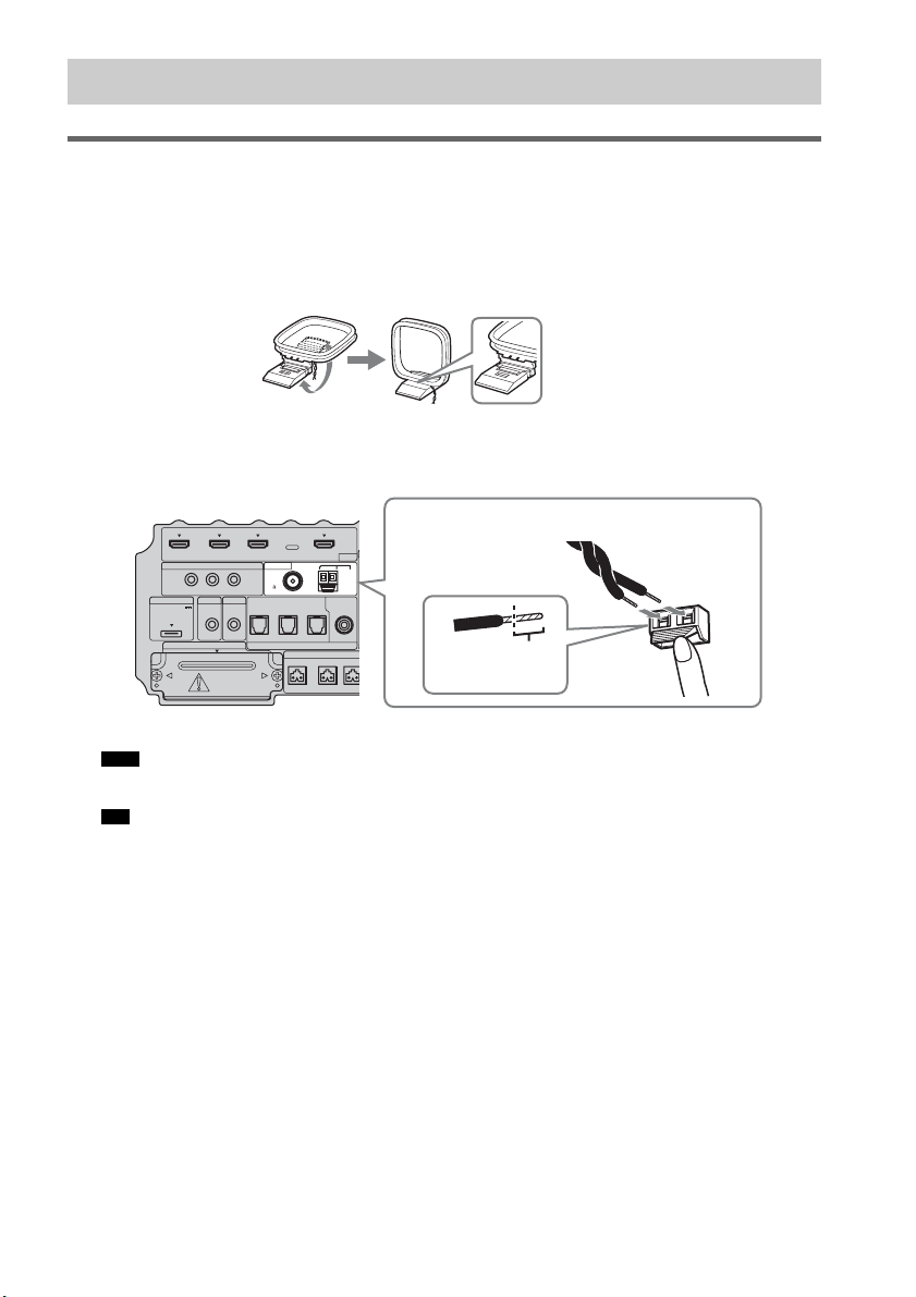
Connecting the AM loop antenna (aerial)
The shape and the length of the antenna (aerial) is designed to receive AM signals. Do not dismantle
or roll up the antenna (aerial).
1 Remove only the loop part from the plastic stand.
2 Set up the AM loop antenna (aerial).
3 Connect the cords to the AM antenna (aerial) terminals.
The cords can be connected to either terminal.
• Do not place the AM loop antenna (aerial) near the system or other AV component, as noise may result.
• Adjust the direction of the AM loop antenna (aerial) for best AM broadcast sound.
4 Make sure the AM loop antenna (aerial) is connected firmly by pulling softly.
Step 4: Connecting the Antenna (Aerial)
Note
Tip
IR REMOTE
DMPORT
SPEAKER ONLY
F
ECM-AC2 IR-R100
ANTENNA
HDMI
IR IN IR OUT1 IR OUT2
FM AM
75
COAXIAL
DC 5V
0.7A MAX
FRONT R FRONT
L
CENTER
BD IN DVD IN SAT IN
SAT IN
ASSIGNABLE
COAXIAL
A
TV OUT
EZW-T100 DIGITAL
TV IN DVD IN SAT IN
OPTICAL
Insert until this
part.
Insert the cords by pushing down the terminal clamp.
Bottom of the subwoofer
23
GB
Getting Started
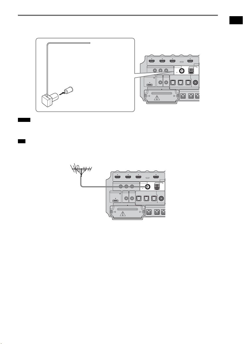
Connecting the FM wire antenna (aerial)
Connect the FM wire antenna (aerial) to the FM 75 Ω COAXIAL jack.
• Be sure to fully extend the FM wire antenna (aerial).
• After connecting the FM wire antenna (aerial), keep it as horizontal as possible.
• If you have poor FM reception, use a 75-ohm coaxial cable (not supplied) to connect the subwoofer to an outdoor
FM antenna (aerial) as shown below.
Notes
Tip
IR REMOTE
DMPORT
SPEAKER ONLY
F
ECM-AC2 IR-R100
ANTENNA
HDMI
IR IN IR OUT1 IR OUT2
FM AM
75
COAXIAL
DC 5V
0.7A MAX
FRONT R FRONT
L
CENTER
BD IN DVD IN SAT IN
SAT IN
ASSIGNABLE
COAXIAL
A
TV OUT
EZW-T100 DIGITAL
TV IN DVD IN SAT IN
OPTICAL
FM wire antenna (aerial)
(supplied)
FM 75 Ω COAXIAL jack
Bottom of the subwoofer
IR REMOTE
DMPORT
SPEAKER ONLY
F
ECM-AC2 IR-R100
ANTENNA
HDMI
IR IN IR OUT1 IR OUT2
FM AM
75
COAXIAL
DC 5V
0.7A MAX
FRONT R FRONT
L
CENTER
BD IN DVD IN SAT IN
SAT IN
ASSIGNABLE
COAXIAL
A
TV OUT
EZW-T100 DIGITAL
TV IN DVD IN SAT IN
OPTICAL
Outdoor FM antenna
(aerial)
Bottom of the subwoofer
24
GB
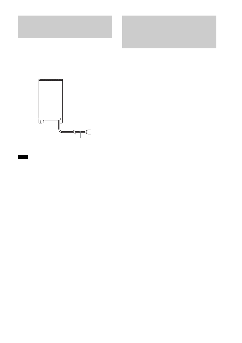
Before connecting the AC power cord (mains
lead) of the subwoofer to a wall outlet (mains),
connect all the speakers to the subwoofer
(page 15).
• After connecting the AC power cord (mains lead),
wait about 20 seconds before turning on the power by
pressing "/1.
This subwoofer is equipped with D.C.A.C.
(Digital Cinema Auto Calibration) Technology
which allows you to perform automatic
calibration as follows:
• Check the connection between each speaker
and the subwoofer.
• Adjust the speaker level.
• Measure the distance of each speaker to your
listening position.
• Measure the frequency characteristics.*
* The measurement result is not utilized for signals
with a sampling frequency of more than 96 kHz.
The D.C.A.C. is designed to obtain proper sound
balance in your room. However, you can adjust
the speaker levels and balance manually
according to your preference. For details, see
“Setting the speaker level” (page 57).
Step 5: Connecting the AC
Power Cord (Mains Lead)
Note
AC power cord
(mains lead)
To a wall outlet
(mains)
Rear of the subwoofer
Step 6: Calibrating the
Appropriate Settings
Automatically
(Auto Calibration)
25
GB
Getting Started
Before performing the Auto
Calibration
Before you perform the Auto Calibration, set up
and connect the speakers (page 15).
• The ECM-AC2 jack is used for the calibration
mic (supplied) only. Do not connect other
microphones to this jack. Doing so may
damage the subwoofer and the calibration mic.
• During the calibration, the sound that comes
out of the speakers is very loud. Pay attention
to the presence of children or to the effect on
your neighborhood.
• Perform the Auto Calibration in a quiet
environment to avoid the effect of noise and to
get a more accurate measurement.
• If there are any obstacles in the path between
the calibration mic and the speakers, the
calibration cannot be performed correctly.
Remove any obstacles from the measurement
area to avoid measurement error.
• If the muting function is on when you perform the
Auto Calibration, it will turn off automatically.
• When you use the S-AIR product, disconnect the
headphones.
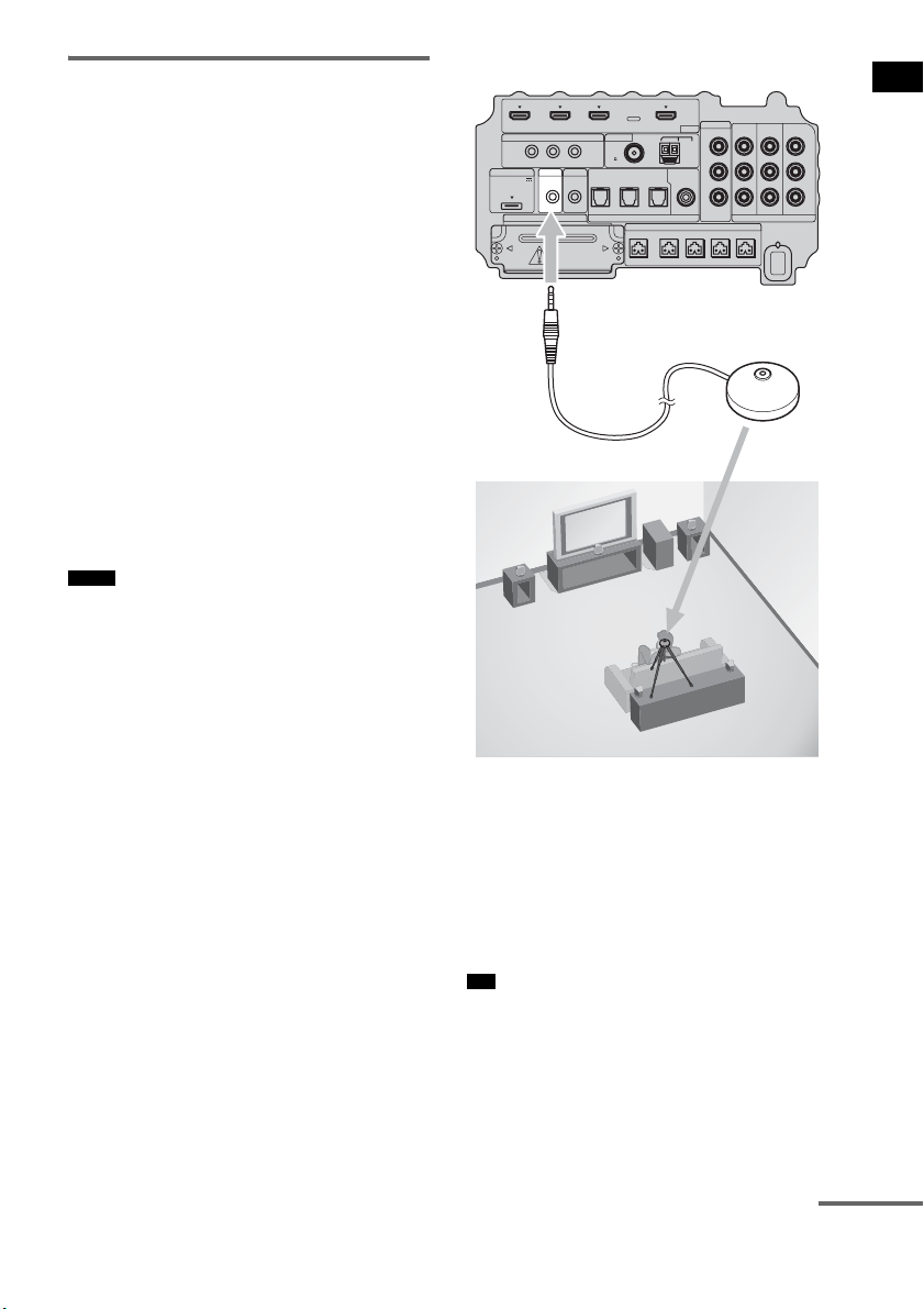
1 Connect the calibration mic (supplied)
to the ECM-AC2 jack on the subwoofer.
2 Set up the calibration mic.
Place the calibration mic at your listening
position. You can also use a stool or tripod
so that the calibration mic remains at the
same height as your ears.
• The front of each speaker should face the calibration
mic. You will get a more accurate measurement.
Notes
Tip
IR REMOTE
VIDEO
DMPORT
SPEAKER ONLY FOR SS-IS15
ECM-AC2 IR-R100
ANTENNA
HDMI
IR IN IR OUT1 IR OUT2
FM AM
75
COAXIAL
DC 5V
0.7A MAX
FRONT R FRONT L SUR R SUR LCENTER
BD IN DVD IN SAT IN
SAT IN
ASSIGNABLE
COAXIAL
AUDI O IN
ASSIGNABLE
VIDEO IN
L
R
TV OUT
EZW-T100 DIGITAL
TV IN DVD IN SAT IN
OPTICAL
COMPONENT VIDEO
DVD IN SAT IN
MONITOR
OUT
Y
P
B/
C
B
PR/
C
R
Bottom of the subwoofer
To ECM-AC2 jack
Calibration mic
continuedcontinued
26
GB
Performing the Auto
Calibration
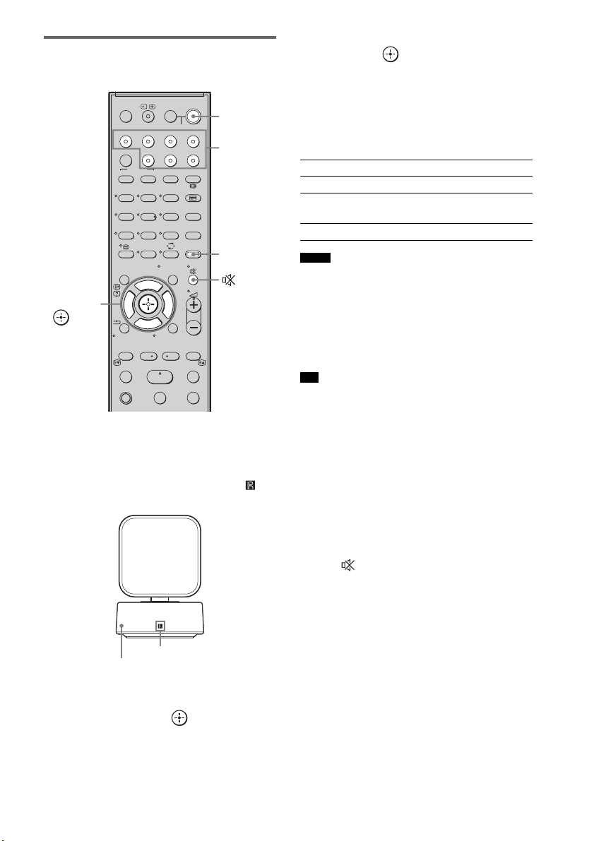
1 Press ?/1.
The system turns on.
2 Press AMP MENU.
Point the remote at the remote sensor ( ) on
the remote commander receiver.
3 Press x/X repeatedly until “A. CAL
MENU” appears on the top panel
display, then press or c.
4 Press x/X to select “A. CAL START,”
then press .
The Auto Calibration starts after the
countdown.
The measurement process will take
approximately 30 seconds to complete.
The table below shows the display when
measurement starts.
• If “PHONES” appears, you cannot perform the Auto
Calibration. Disconnect the headphones from the S-
AIR product you are using, then restart the Auto
Calibration.
• If “CHECK MIC” appears, you cannot perform the
Auto Calibration. Connect the calibration mic, then
restart the Auto Calibration.
• When the Auto Calibration starts:
– Stand some distance from the speakers and the
listening position to avoid measurement failure. This
is because test signals are output from the speakers
during measurement.
– Avoid making noise to get a more accurate
measurement.
To cancel the Auto Calibration
The Auto Calibration function will be canceled
when you do the following during the
measurement process:
–Press .
– Press input buttons on the remote or INPUT
SELECTOR on the subwoofer.
– Change the volume level.
123
46
78
0
ENTERCLEAR
9
THEATRE
TV
?/1
AV
?/1
TV BD DVD SAT
TOP MENU MENU
BD/DVD
RETURN/EXIT
TV
F1 F2
AMP MENU
DISPLAY
TONE
TUNING - TUNING +
NIGHT
MODE
A/BDIGITALANALOG
DMPORTTUNER/BANDVIDEO
SOUND FIELD
?/1
TV CH -
PRESET -
TV CH +
PRESET +
F
Gg
f
.
HmM
Xx
<
<
>
5
SYSTEM STANDBY
MENU/HOME
TOOLS/
OPTIONS
C, X, x, c,
?/1
AMP
MENU
Input
buttons
Remote commander receiver
Remote sensor
Measurement for Display
Speaker existance TONE
Speaker gain, distance, frequency
response
T.S.P.
Subwoofer gain and distance SUBWOOFER
Notes
Tip
27
GB
Getting Started
Confirming/saving the
measurement result
1 Confirm the measurement result.
When the measurement ends, a beep sounds
and the measurement result appears on the
top panel display.
• After “SAVE EXIT” is displayed for 50 seconds, the
measurement result is saved automatically, without
the need to saving procedure.
2 Press x/X repeatedly to select the
desired item, then press or c. To
return, press C or RETURN.
3 Save the measurement result.
Select “SAVE EXIT” in step 2, then press
.
The measurement result is saved.
When error codes appear
Try the remedies and perform the Auto
Calibration again.
When you select “WRN CHECK”
If a warning on the measurement result is
present, detailed information is displayed.
Item Explanation
SAVE EXIT Saves the measurement result
and exits the setting process.
WRN CHECK Displays warning concerning
the measurement result. See
“When you select “WRN
CHECK”” (page 27).
DIST INFO Displays the measurement
result for speaker distance.
LEVEL INFO Displays the measurement
result for speaker level.
EXIT Exits the setting process
without saving the
measurement result.
Note
Item Explanation
ERROR 32 • The sound input from the
calibration mic is out of the
acceptable range.
• The calibration mic or
subwoofer may be damaged.
Contact your Sony dealer or
local authorized Sony service
facility.
ERROR F 33 The front speakers are not
connected.
Check that the front speakers
are connected properly.
ERROR SR 33 Either the surround left or
surround right speaker is not
connected.
Check that the surround
speakers are connected
properly.
ERROR SW 33 The subwoofer may be
damaged.
Contact your Sony dealer or
local authorized Sony service
facility.
Warning code Explanation
WARNING 40 The Auto Calibration has
completed. However, the noise
level is high. You may be able
to perform the Auto Calibration
properly if you try it again, even
though the measurement cannot
be performed in all
environments. Try to perform
the Auto Calibration in a quiet
environment.
WARNING 41
WARNING 42
The sound input from the
calibration mic is out of the
acceptable range. The distance
between the calibration mic and
the speakers is too closed. Set
them away, and then try to
perform the Auto Calibration.
WARNING 43 The distance and position of the
subwoofer cannot be detected.
This may be caused by noise.
Try to perform the Auto
Calibration in a quiet
environment.
NO WARNING There is no warning
information.
Item Explanation
continued
28
GB
When you select “DIST INFO” or
“LEVEL INFO”
You can check the speaker distance or speaker
level.
• The measurement result of a speaker will not appear if
the subwoofer does not recognize that the speaker is
connected.
After you have finished
Disconnect the calibration mic from the
subwoofer.
• If you have changed the position of the speakers, Sony
recommends that you perform the Auto Calibration
again in order to enjoy the surround sound.
Deleting the result of the Auto
Calibration
You can delete the result of the Auto Calibration.
If there is no saved data, you cannot delete the
result.
1 Press AMP MENU.
2 Press x/X repeatedly until “A.CAL
MENU” appears, then press or c.
3 Press x/X repeatedly to select “A.CAL
CLEAR,” then press or c.
4 Press x/X to select “YES,” then press
.
The saved result is deleted.
The settings for speaker distance and
speaker level return to their defaults.
Depending on the audio output settings of the
connected component, the sound may output in 2
channel sound format only. In this case, set the
connected component to output the sound in
multi channel sound format (PCM, DTS, Dolby
Digital). For details on audio output settings,
refer to the operating instructions of the
connected component.
Note
Note
Setting up the Sound
Output of the Connected
Component
29
GB
Getting Started
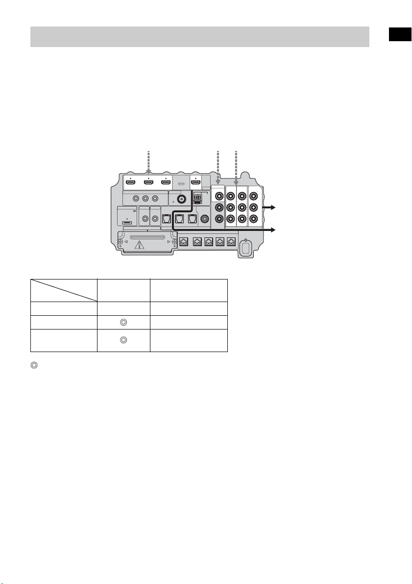
The subwoofer is equipped with a function for converting video signals.
Video signals and component video signals can be output as HDMI video signals and these up-
converted video signals can only be output from the HDMI TV OUT jack. See the illustration that
follows.
In the video input/output conversion table of the subwoofer
: Video signals are up-converted and output through the video converter.
a : The same type of signal as that of the input signal is output. Video signals are not up-converted.
X : Video signals are not output.
Notes on converting video signals
• When video signals from a VCR, etc., are converted on the subwoofer and then output to your TV,
depending on the status of the video signal output, the image on the TV screen may appear distorted
horizontally, or no image may be output.
• HDMI video signals cannot be converted to component video signals.
• The up-converted video signals are output only from the HDMI OUT jack. They are not output from
any other video jacks.
• When you play back a VCR with an image improvement circuit, such as TBC, the images may be
distorted or may not be output. In this case, set the image improvement circuit function to off.
Function for Conversion of Video Signals
HDMI TV OUT
COMPONENT VIDEO
MONITOR OUT
HDMI IN A a X
VIDEO IN B X
COMPONENT
VIDEO IN C
a
IR REMOTE
DMPORT
SPEAKER ONLY FOR SS-IS15
ECM-AC2 IR-R100
ANTENNA
IR IN IR OUT1 IR OUT2
FM AM
75
COAXIAL
DC 5V
0.7A MAX
FRONT R FRONT L SUR R SUR LCENTER
AUDI O IN
ASSIGNABLE
L
R
EZW-T100 DIGITAL
TV IN DVD IN SAT IN
OPTICAL
COMPONENT VIDEO
DVD IN SAT IN
MONITOR
OUT
Y
P
B/
C
B
PR/
C
R
SAT IN
ASSIGNABLE
COAXIAL
VIDEO
VIDEO IN
HDMI
BD IN DVD IN SAT IN TV OUT
Input signals
ABC
C
ABC
Output signalsBottom of the
subwoofer
INPUT jack
OUTPUT jack
30
GB
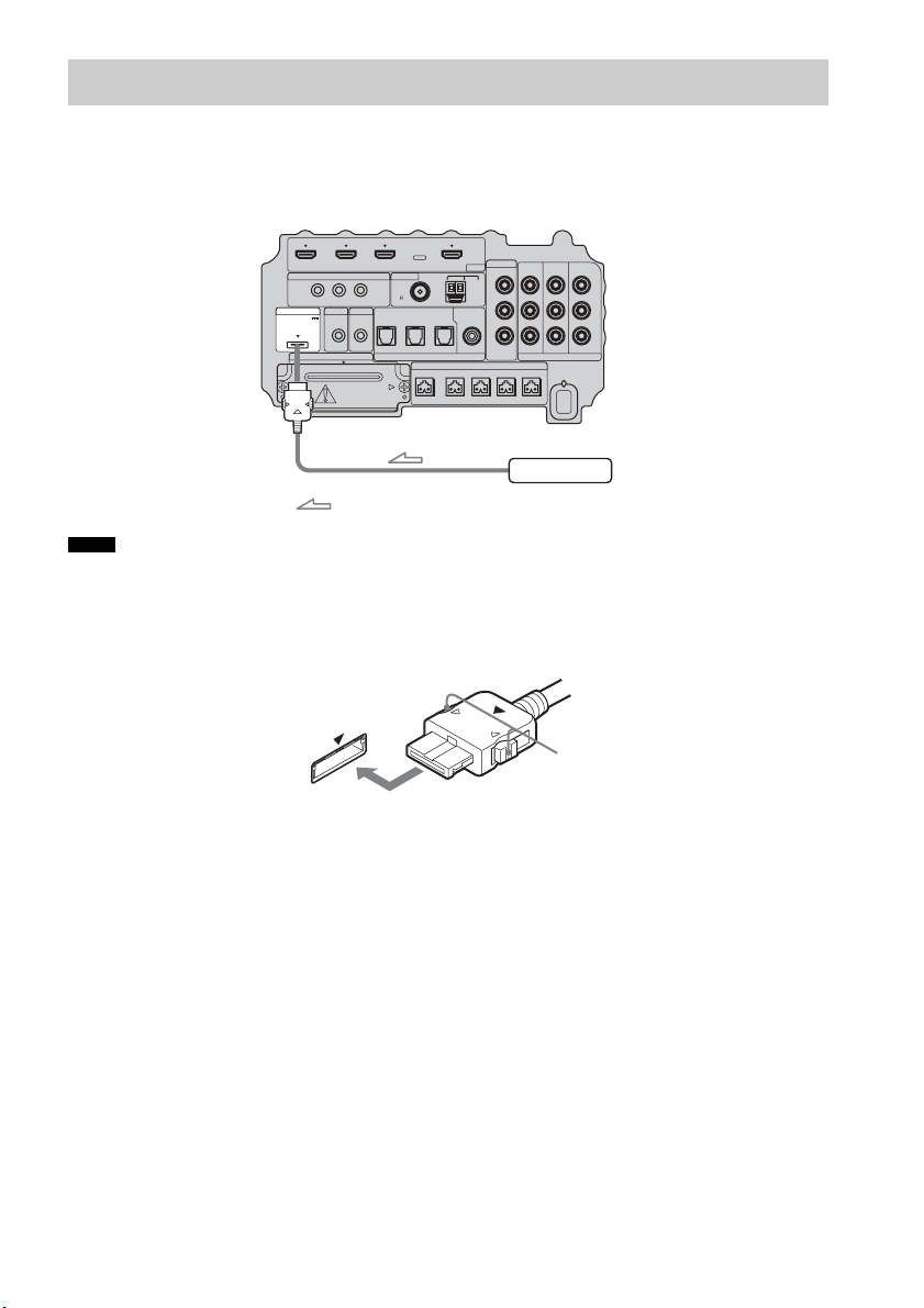
To connect the DIGITAL MEDIA PORT adapter
You can enjoy sound from a component connected to the subwoofer, using the DIGITAL MEDIA
PORT adapter.
• Do not connect or disconnect the DIGITAL MEDIA PORT adapter while the system is turned on.
• When you connect the DIGITAL MEDIA PORT adapter, be sure the connector is inserted with the arrow mark
facing toward the arrow mark on the DMPORT jack. To detach the DIGITAL MEDIA PORT adapter, press and
hold
A and then pull out the connector.
Connecting the Other Components
Notes
IR REMOTE
VIDEO
DMPORT
SPEAKER ONLY FOR SS-IS15
ECM-AC2 IR-R100
ANTENNA
HDMI
IR IN IR OUT1 IR OUT2
FM AM
75
COAXIAL
DC 5V
0.7A MAX
FRONT R FRONT L SUR R SUR LCENTER
BD IN DVD IN SAT IN
SAT IN
ASSIGNABLE
COAXIAL
AUDI O IN
ASSIGNABLE
VIDEO IN
L
R
TV OUT
EZW-T100 DIGITAL
TV IN DVD IN SAT IN
OPTICAL
COMPONENT VIDEO
DVD IN SAT IN
MONITOR
OUT
Y
P
B/
C
B
PR/
C
R
DIGITAL MEDIA PORT adapter
: Signal flow
Bottom of the
subwoofer
A
31
GB
Getting Started
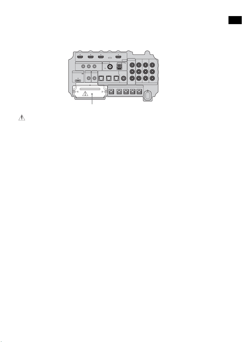
To use the wireless system
The system is compatible with the S-AIR function, which allows sound transmission between the
subwoofer and S-AIR product (not supplied). When you purchase the S-AIR product, you need to
establish sound transmission.
For details, see page 65.
CAUTION
• There is no need to open the slot cover until the S-AIR product is used.
IR REMOTE
VIDEO
DMPORT
SPEAKER ONLY FOR SS-IS15
ECM-AC2 IR-R100
ANTENNA
HDMI
IR IN IR OUT1 IR OUT2
FM AM
75
COAXIAL
DC 5V
0.7A MAX
FRONT R FRONT L SUR R SUR LCENTER
BD IN DVD IN SAT IN
SAT IN
ASSIGNABLE
COAXIAL
AUDI O IN
ASSIGNABLE
VIDEO IN
L
R
TV OUT
EZW-T100 DIGITAL
TV IN DVD IN SAT IN
OPTICAL
COMPONENT VIDEO
DVD IN SAT IN
MONITOR
OUT
Y
P
B/
C
B
PR/
C
R
Slot cover
Bottom of the
subwoofer
32
GB
For more information, see the pages indicated in parentheses.
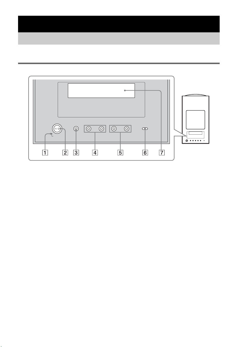
Top panel
A POWER / ACTIVE STANDBY
Green: the system turns on.
Amber: the Control for HDMI function or the S-AIR STANDBY MODE function is working
while the system is turned off.
No light: the system is turned off, and the Control for HDMI function and the S-AIR STANDBY
MODE function is not working.
B ?/1 (on/standby)
Press to turn the system on or off.
C INPUT SELECTOR
Press to select the input source to play back.
D PRESET –/+
Press to go to the previous/next preset radio station.
E VOLUME –/+
Press to adjust the volume level.
F S-AIR
Green: the S-AIR transmitter (not supplied) is inserted in the subwoofer and the system
establishes sound transmission.
No light: the system does not establish sound transmission by the S-AIR function.
G Top panel display
Check the system status.
Playback Options
Index to Parts and Controls
-
VOLUME +
-
PRESET +INPUT SELECTOR
POWER/
ACTIVE STANDBY
33
GB
Playback Options
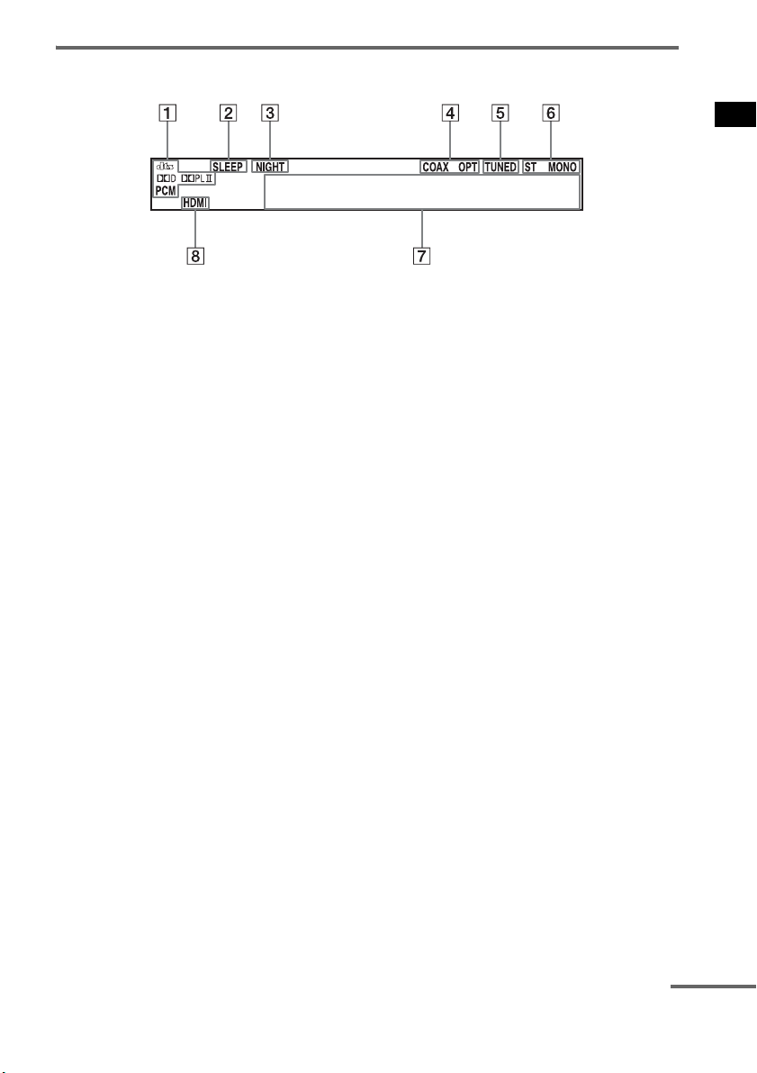
About the indications in the top panel display
A Lights up according to the audio input signals.
B SLEEP (62)
Flashes when the Sleep Timer function is active.
C NIGHT (40)
Lights up when the night mode is on.
D COAX/OPT
Lights up according to the coaxial or optical signal being input.
E TUNED (46)
Lights up when a radio station is received.
F ST/MONO (47)
Lights up according to the stereo or monaural status of the radio.
G Displays system’s status.
Radio frequency, sound field, etc.
H HDMI (16, 74)
Lights up when an HDMI component is being used.
continued
34
GB
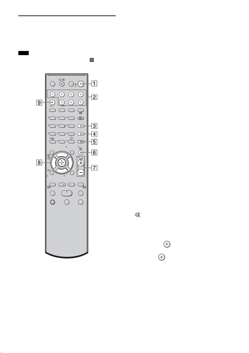
Remote control
Here describes the buttons for amplifier
operation only. See page 50 for the buttons for
operation of the connected components.
• Point the remote at the remote sensor ( ) on the
remote commander receiver.
* The 5, H, and
2 + buttons have a tactile dot. Use
it as a guide during operation.
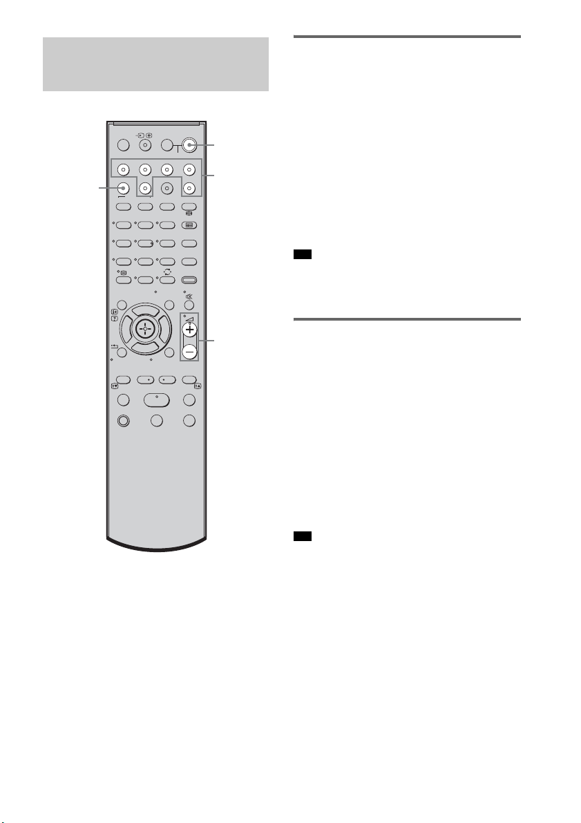
A ?/1 (on/standby)
Press to turn the system on or off.
To save the power in standby mode
Press ?/1 while the system turns on.
To enter power saving mode, make sure that
the system is in the following status.
– “CTRL: HDMI” is set to “CTRL OFF”
(page 41).
– “S-AIR STBY” is set to “STBY OFF”
(page 71).
To cancel standby mode, press
?/1 once.
B Input buttons
Press one of the buttons to select the
component you want to use.
The buttons are factory assigned to control
Sony components. You can change the
factory settings of the input buttons to suit
the components in your system. For details,
see “Changing the Input Button
Assignments of the Remote” (page 53).
C TONE
Press to adjust the bass, middle, and treble
level (page 40).
D NIGHT MODE
Press to enjoy sound effects for watching
movies at night (page 40).
E AMP MENU
Press to display the menu of the system
(page 54).
F (MUTING)
Press to turn off the sound.
G 2 +/–
Press to adjust the volume.
H C, X, x, c or
Press C, X, x or c to select the settings.
Then press to enter the selection.
I SOUND FIELD
Press to select the sound field (page 38).
Note
123
46
78
0
ENTERCLEAR
9
THEATRE
TV
?/1
AV
?/1
TV BD DVD SAT
TOP MENU MENU
BD/DVD
RETURN/EXIT
TV
F1 F2
AMP MENU
DISPLAY
TONE
TUNING - TUNING +
NIGHT
MODE
A/BDIGITALANALOG
DMPORTTUNER/BANDVIDEO
SOUND FIELD
?/1
TV CH -
PRESET -
TV CH +
PRESET +
F
Gg
f
.
HmM
Xx
<
<
>
5
SYSTEM STANDBY
MENU/HOME
TOOLS/
OPTIONS
35
GB
Playback Options
1 Turn on the TV and choose a program.
For details, refer to the operating
instructions of the TV.
2 Turn the system on.
3 Press TV (white) on the remote.
4 Adjust the volume of the system.
• When you connect a Sony TV, the audio input of the
TV is switched and the image from the TV tuner is
displayed on the TV screen automatically by pressing
the TV (white) button. To change this setting, see
“Changing the Input Button Assignments of the
Remote” (page 53).
• The sound may be output from the TV’s speaker. In
this case, turn the volume of the TV’s speaker down
to the minimum.
Enjoying TV
123
46
78
0
ENTERCLEAR
9
THEATRE
TV
?/1
AV
?/1
TV BD DVD SAT
TOP MENU MENU
BD/DVD
RETURN/EXIT
TV
F1 F2
AMP MENU
DISPLAY
TONE
TUNING - TUNING +
NIGHT
MODE
A/BDIGITALANALOG
DMPORTTUNER/BANDVIDEO
SOUND FIELD
?/1
TV CH -
PRESET -
TV CH +
PRESET +
F
Gg
f
.
HmM
Xx
<
<
>
5
SYSTEM STANDBY
MENU/HOME
TOOLS/
OPTIONS
?/1
2 +/–
TV
(white)
Tips
36
GB
Enjoying a satellite tuner
1 Turn on the TV.
For details, refer to the operating
instructions of the TV.
2 Turn the satellite tuner and the system
on.
3 Press SAT on the remote.
4 Change the TV input.
For details, refer to the operating
instructions of the TV.
5 Adjust the volume of the system.
• The sound may be output from the TV’s speaker. In
this case, turn the volume of the TV’s speaker down
to the minimum.
Enjoying Blu-ray Disc, DVD, or
“PlayStation 3”
1 Turn on the TV.
2 Turn the Blu-ray Disc/DVD player
(recorder) or “PlayStation 3” and the
system on.
3 Press DVD or BD on the remote.
4 Change the TV input.
For details, refer to the operating
instructions of the TV.
5 Play back the disc.
• Even if you playback Dolby True HD, Dolby Digital
Plus or DTS-HD with a connected component
compatible with these sound formats, the system
accepts as Dolby Digital or DTS. When you connect
the component to the system using an HDMI cable to
playback these high-quality sound formats, set the
connected component to output the sound in multi
channel PCM, if possible.
Enjoying Other
Components
123
46
78
0
ENTERCLEAR
9
THEATRE
TV
?/1
AV
?/1
TV BD DVD SAT
TOP MENU MENU
BD/DVD
RETURN/EXIT
TV
F1 F2
AMP MENU
DISPLAY
TONE
TUNING - TUNING +
NIGHT
MODE
A/BDIGITALANALOG
DMPORTTUNER/BANDVIDEO
SOUND FIELD
?/1
TV CH -
PRESET -
TV CH +
PRESET +
F
Gg
f
.
HmM
Xx
<
<
>
5
SYSTEM STANDBY
MENU/HOME
TOOLS/
OPTIONS
?/1
2 +/–
Input
buttons
SOUND
FIELD
Tip
Tip

37
GB
Playback Options
Enjoying a VCR
1 Turn on the TV.
2 Turn the VCR player and the system on.
3 Press VIDEO on the remote.
4 Change the TV input.
For details, refer to the operating
instructions of the TV.
5 Play back the tape on the VCR.
Enjoying a connected
component through DMPORT
connection
1 Press DMPORT on the remote.
2 Start playback of the connected
component.
• When listening to MP3 or other compressed music
files using a portable audio source, you can enhance
the sound. Press SOUND FIELD repeatedly until “P.
AUDIO” appears in the top panel display.
Tip
38
GB
Selecting the sound field
This system can create multi channel surround
sound. You can select one of the optimized
sound fields from the system’s preprogrammed
sound fields.
Enjoying Surround Sound
Using Sound Field
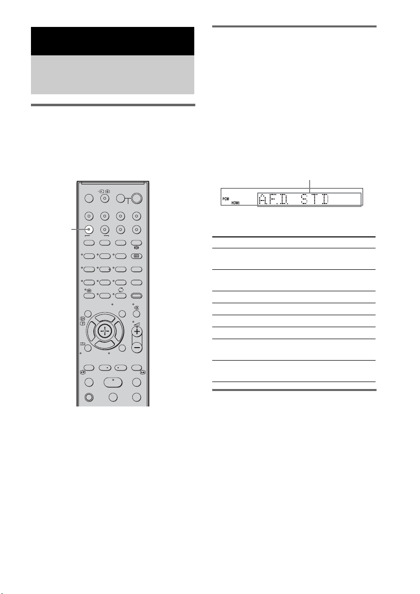
Press SOUND FIELD.
The present sound field appears.
Each time you press the SOUND FIELD button,
the display changes cyclically as follows:
A.F.D. STD t A.F.D. MULTI t
PLII MOVIE t PLII MUSIC t SPORTS t
NEWS t P. AUDIO t OMNI-DIR t
A.F.D. STD t ...
Press SOUND FIELD repeatedly until the sound
field you want appears.
Available sound fields
Automatic outputting of the
original sound
x AUTO FORMAT DIRECT STANDARD
The auto decoding function automatically
detects the type of audio signal being input
(Dolby Digital, DTS, or standard 2 channel
stereo) and performs the proper decoding if
necessary. This mode presents the sound as it
was recorded/encoded, without adding any
effects (e.g. reverberation).
However, if there are no low frequency signals
(Dolby Digital LFE, etc.), it will generate a low
frequency signal for output to the subwoofer.
Surround Functions
Enjoying the Surround
Effects
123
46
78
0
ENTERCLEAR
9
THEATRE
TV
?/1
AV
?/1
TV BD DVD SAT
TOP MENU MENU
BD/DVD
RETURN/EXIT
TV
F1 F2
AMP MENU
DISPLAY
TONE
TUNING - TUNING +
NIGHT
MODE
A/BDIGITALANALOG
DMPORTTUNER/BANDVIDEO
SOUND FIELD
?/1
TV CH -
PRESET -
TV CH +
PRESET +
F
Gg
f
.
HmM
Xx
<
<
>
5
SYSTEM STANDBY
MENU/HOME
TOOLS/
OPTIONS
SOUND
FIELD
Sound field Display
AUTO FORMAT DIRECT
STANDARD
A.F.D. STD
AUTO FORMAT DIRECT
MULTI
A.F.D. MULTI
Dolby Pro Logic II MOVIE PLII MOVIE
Dolby Pro Logic II MUSIC PLII MUSIC
SPORTS SPORTS
NEWS NEWS
PORTABLE AUDIO
ENHANCER
P. AUDIO
OMNI-DIRECTIONAL
SOUND
OMNI-DIR
Display area

39
GB
Surround Functions
Outputting the sound from
multiple speakers
x AUTO FORMAT DIRECT MULTI
This mode lets you enjoy audio playback of all
types of discs from multiple speakers.
• The sound is not output from multiple speakers
depending on the source.
• Depending on the disc or source, the beginning of the
sound may be cut off as the optimum mode is
automatically selected. To avoid cutting the sound,
select “A.F.D. STD.”
Outputting 2 channel sources
like CDs by 5.1channel
x Dolby Pro Logic II MOVIE/MUSIC
Dolby Pro Logic II produces five full-bandwidth
output channels from 2 channel sources. This is
done using an advanced, high-purity matrix
surround decoder that extracts the spatial
properties of the original recording without
adding any new sounds or tonal colorations.
• When the input signal is multi channel source, Dolby
Pro Logic II MOVIE/MUSIC are canceled and the
multi channel source is output directly.
• When the bilingual broadcast sound is input, Dolby
Pro Logic II MOVIE/MUSIC are not effective.
Enjoying the sound effects
x SPORTS
This mode produces clear play-by-play
commentary and realistic sound with surround
effects, such as cheering, etc.
x NEWS
This mode produces the clear announcer’s voice.
x PORTABLE AUDIO ENHANCER
This mode reproduces a clear enhanced sound
image from your portable audio device. This
mode is ideal for MP3 and other compressed
music.
• Multi channel Linear PCM is not available for “P.
AUDIO.”
x OMNI-DIRECTIONAL SOUND
This mode reproduces the stereo effect
everywhere surrounding by five satellite
speakers.
To turn the surround effect off
Press SOUND FIELD repeatedly until “A.F.D.
STD” appears in the top panel display.
• The sound fields memorized for each input are
retained even if you disconnect the AC power cord
(mains lead).
Whenever you select a function such as “DVD” or
“TUNER,” the sound field that was last applied to
function is automatically applied again. For example,
if you listen to DVD with Dolby Pro Logic II MOVIE
as the sound field, then change to another function,
and then return to DVD, Dolby Pro Logic II MOVIE
will be applied again.
Notes
Notes
Note
Tip
40
GB
You can adjust the bass, middle, and treble level
easily.
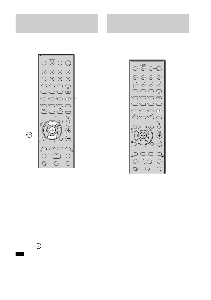
1 Press TONE repeatedly until “BASS,”
“MIDDLE,” or “TREBLE” appears in the
top panel display.
• BASS: adjusts the bass level
(–6.0 – +6.0 dB, 0.5 dB steps).
• MIDDLE: adjusts the middle level
(–6.0 – +6.0 dB, 0.5 dB steps).
• TREBLE: adjusts the treble level
(–6.0 – +6.0 dB, 0.5 dB steps).
2 Press X/x to adjust.
The adjusted value appears in the top panel
display.
3 Press .
• When you use the S-AIR functions with the
headphones, “MIDDLE” appears. However, middle
level is not available for the headphones.
You can enjoy sound effects or dialog, as you
would in a movie theatre, even at low volume. It
is useful for watching movies at night.
Press NIGHT MODE.
“NIGHT” lights up in the top panel display and
the sound effect is activated.
To turn off the sound effect
Press NIGHT MODE again.
Adjusting the Bass,
Middle, and Treble Level
Note
123
46
78
0
ENTERCLEAR
9
THEATRE
TV
?/1
AV
?/1
TV BD DVD SAT
TOP MENU MENU
BD/DVD
RETURN/EXIT
TV
F1 F2
AMP MENU
DISPLAY
TONE
TUNING - TUNING +
NIGHT
MODE
A/BDIGITALANALOG
DMPORTTUNER/BANDVIDEO
SOUND FIELD
?/1
TV CH -
PRESET -
TV CH +
PRESET +
F
Gg
f
.
HmM
Xx
<
<
>
5
SYSTEM STANDBY
MENU/HOME
TOOLS/
OPTIONS
TONE
X, x,
Enjoying the Movies at
Night
123
46
78
0
ENTERCLEAR
9
THEATRE
TV
?/1
AV
?/1
TV BD DVD SAT
TOP MENU MENU
BD/DVD
RETURN/EXIT
TV
F1 F2
AMP MENU
DISPLAY
TONE
TUNING - TUNING +
NIGHT
MODE
A/BDIGITALANALOG
DMPORTTUNER/BANDVIDEO
SOUND FIELD
?/1
TV CH -
PRESET -
TV CH +
PRESET +
F
Gg
f
.
HmM
Xx
<
<
>
5
SYSTEM STANDBY
MENU/HOME
TOOLS/
OPTIONS
NIGHT
MODE
41
GB
“BRAVIA” Sync features
By connecting Sony components that are
compatible with the “BRAVIA” Sync with an
HDMI cable (not supplied), operation is
simplified as below:
• One-Touch Play: When you play back a
component such as a Blu-ray Disc/DVD player
(recorder), the system and the TV are turned on
automatically and switch to the appropriate
HDMI input.
• System Audio Control: While watching TV,
you can select to output the sound from the TV
speaker or the speakers of the system.
• System Power Off: When you turn off the TV,
the system and the connected components are
also turned off simultaneously.
“BRAVIA” Sync is compatible with a Sony TV,
Blu-ray Disc/DVD player, AV amplifier, etc.,
with the Control for HDMI function.
Control for HDMI is a mutual control function
standard used by CEC (Consumer Electronics
Control) for HDMI (High-Definition
Multimedia Interface).
The Control for HDMI function will
not operate in the following
cases:
• When you connect this system to a component
which does not correspond with the Control for
HDMI function.
• When you connect the system and components
using other than HDMI connection.
Sony recommends that you connect this system
to products featuring “BRAVIA” Sync.
• Depending on the connected component, the Control
for HDMI function may not work. For details, refer to
the operating instructions of the component.
To use the “BRAVIA” Sync, set the Control for
HDMI function to on for the system and the
connected component.
When you connect a Sony TV with the Control
for HDMI function, the Control for HDMI
function for the system and the connected
component can be set simultaneously by setting
the Control for HDMI function of the TV.
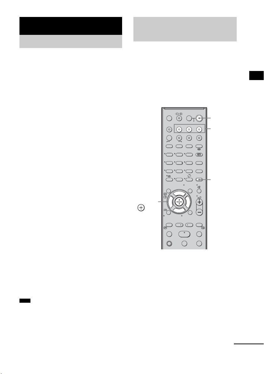
1 Make sure that the system is connected
to the TV and the connected
components (which should be
compatible with the Control for HDMI
function) using HDMI cables (not
supplied).
2 Turn on the system, the TV, and the
connected components.
“BRAVIA” Sync features
What is “BRAVIA” Sync?
Note
Preparing for the
“BRAVIA” Sync
123
46
78
0
ENTERCLEAR
9
THEATRE
TV
?/1
AV
?/1
TV BD DVD SAT
TOP MENU MENU
BD/DVD
RETURN/EXIT
TV
F1 F2
AMP MENU
DISPLAY
TONE
TUNING - TUNING +
NIGHT
MODE
A/BDIGITALANALOG
DMPORTTUNER/BANDVIDEO
SOUND FIELD
?/1
TV CH -
PRESET -
TV CH +
PRESET +
F
Gg
f
.
HmM
Xx
<
<
>
5
SYSTEM STANDBY
MENU/HOME
TOOLS/
OPTIONS
?/1
AMP
MENU
Input
buttons
C, X, x, c,
continued

42
GB
3 Select the input of the system
connected to the component you want
to watch (BD, DVD, SAT), and switch
the HDMI input of the TV, so that an
image from the connected component
is displayed.
4 Set the Control for HDMI function of the
TV to on.
The Control for HDMI function for the
system and the connected component is
simultaneously set to on.
During the setting, “SCANNING” appears
in the top panel display. After you finish the
setting, “COMPLETE” appears in the top
panel display. Wait until the setting is
complete.
If “SCANNING” or “COMPLETE”
does not appear after performing
the steps above
Set the Control for HDMI function to on for the
system and the connected component
individually.
1 Press AMP MENU.
2 Press x/X repeatedly until “SET HDMI”
appears, then press or c.
3 Press x/X repeatedly until “CTRL:
HDMI” appears, then press or c.
4 Press x/X to select “CTRL ON,” then
press or c.
5 Press AMP MENU.
The AMP menu turns off. The Control for
HDMI function is set to on.
6 Set the Control for HDMI function of the
connected component to on.
For details, refer to the operating
instructions of the connected component.
7 Select the input of the system
connected to the component you want
to use the Control for HDMI function for
(BD, DVD, SAT), and repeat step 6.
If you add or reconnect the
component
Perform steps of “Preparing for the “BRAVIA”
Sync” and “If “SCANNING” or “COMPLETE”
does not appear after performing the steps
above” again.
• During the setting of the Control for HDMI function
for the system, the System Audio Control function
does not work.
• If the Control for HDMI function for the connected
component cannot be set simultaneously by setting
“Control for HDMI” of the TV, set the Control for
HDMI function using the menu of the connected
component.
• For details on setting the TV and the connected
components, refer to their operating instructions.
• The default setting of the Control for HDMI function
of the system is “OFF.”
Notes
Tip
43
GB
“BRAVIA” Sync features
Play back a connected component.
The system and the TV are turned on
automatically and switch to the appropriate
HDMI input.
• Depending on the TV, the start of the content may not
be output.
• You can enjoy the Blu-ray Disc/DVD player
(recorder) connected to the system, even if you turn
the system off. The POWER / ACTIVE STANDBY
indicator lights up in amber at this time.
You can enjoy the TV sound from the speakers
of the system by means of a simple operation.
For details, refer to the operating instructions of
the TV.
Press ?/1 to turn on the system.
The sound is output from the speakers of the
system. The sound is output from the TV's
speaker when you turn the system off.
• When the TV is turned on before this system is turned
on, the TV sound will not be output for a moment.
• You can adjust the volume and turn off the sound of
the system using the TV remote.
Enjoying a Blu-ray Disc/
DVD
(One-Touch Play)
Note
Tip
Enjoying the TV sound
from the Speakers
(System Audio Control)
Note
Tip
123
46
78
0
ENTERCLEAR
9
THEATRE
TV
?/1
AV
?/1
TV BD DVD SAT
TOP MENU MENU
BD/DVD
RETURN/EXIT
TV
F1 F2
AMP MENU
DISPLAY
TONE
TUNING - TUNING +
NIGHT
MODE
A/BDIGITALANALOG
DMPORTTUNER/BANDVIDEO
SOUND FIELD
?/1
TV CH -
PRESET -
TV CH +
PRESET +
F
Gg
f
.
HmM
Xx
<
<
>
5
SYSTEM STANDBY
MENU/HOME
TOOLS/
OPTIONS
?/1
AMP
MENU
Input
buttons
C, X, x, c,
continued

44
GB
Using the Volume Limit
function
When the System Audio Control function is
active, and the output method changes from the
TV speaker to the system speaker automatically,
loud sound may be output depending on the
volume level of the system. You can prevent this
by limiting the maximum volume level.
1 Press AMP MENU.
2 Press x/X repeatedly until “SET HDMI”
appears, then press or c.
3 Press x/X repeatedly until “VOL LIMIT”
appears, then press or c.
4 Press x/X to select the maximum
volume level you want.
The maximum volume level changes as
follows:
5 Press AMP MENU.
The AMP menu turns off.
• This function is available only when the Control for
HDMI function is set to on.
• This function is not available when the output method
changes from the system speaker to the TV speaker.
• Sony recommends that you set the maximum volume
level to a little lower than the volume you usually
listen to.
• Regardless of the maximum volume level you set, the
VOLUME +/– button of the subwoofer and the 2 +/
– button of the remote are operable.
• If you do not want to limit the maximum volume
level, select “MAX.”
Using the input buttons of the
remote
The input buttons (TV (white), BD, DVD, SAT,
VIDEO, DMPORT) work as follows when the
Control for HDMI function is set to on.
• BD, DVD, SAT, VIDEO, DMPORT: Since the
input of the TV is also switched automatically,
you can watch the image of the selected
component on the TV simply by pressing the
buttons.
• TV: The input of the TV switches
automatically. When you connect a Sony TV,
you can watch the TV simply by pressing the
button.
• You can control connected Sony components by
pressing the input buttons. For details, see
“Controlling the Connected Sony Components with
the Remote” (page 50).
Notes
Tips
MAX y 49 y 48 y
...... y 2 y 1 y MIN
Tip

45
GB
“BRAVIA” Sync features
When you turn the TV off by using the power
button on the TV’s remote, the system and the
connected components turn off automatically.
Also, when you turn the TV off by using the
system’s remote, the system and the connected
components turn off automatically.
Hold down TV (orange), and press AV
?/1.
The TV, the system, and the connected
components are turned off.
• Depending on the status, the connected components
may not be turned off. For details, refer to the
operating instructions of the connected components.
Turning off the TV,
System, and Connected
Components
(System Power Off)
Note
123
46
78
0
ENTERCLEAR
9
THEATRE
TV
?/1
AV
?/1
TV BD DVD SAT
TOP MENU MENU
BD/DVD
RETURN/EXIT
TV
F1 F2
AMP MENU
DISPLAY
TONE
TUNING - TUNING +
NIGHT
MODE
A/BDIGITALANALOG
DMPORTTUNER/BANDVIDEO
SOUND FIELD
?/1
TV CH -
PRESET -
TV CH +
PRESET +
F
Gg
f
.
HmM
Xx
<
<
>
5
SYSTEM STANDBY
MENU/HOME
TOOLS/
OPTIONS
AV ?/1
TV
(orange)
46
GB
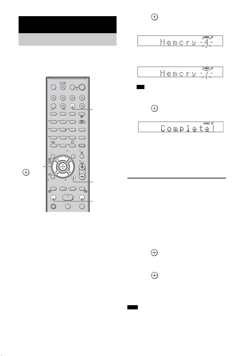
You can preset 20 FM stations, and 10 AM
stations. Before tuning, make sure to turn the
volume down to minimum.
1 Press TUNER/BAND.
You can change “FM” or “AM” by pressing
TUNER/BAND.
2 Press and hold TUNING + or – until the
auto scanning starts.
Scanning stops when the system tunes in a
station. “TUNED” and “ST” (for stereo
program) light up in the top panel display.
3 Press MENU.
4 Press X/x repeatedly until “Memory?”
appears in the top panel display.
5 Press .
A preset number appears in the top panel
display.
6 Press X/x to select the preset number
you want.
• You can select the preset number directly by
pressing the number buttons.
7 Press .
The station is stored.
8 Press MENU.
9 Repeat 2 to 8 to store other stations.
To change the preset number
Restart from step 3.
Changing the AM tuning
interval (for Australian models)
The AM tuning interval can be set to either 10
kHz or 9 kHz.
1 Press TUNER/BAND repeatedly until
“AM” appears in the top panel display.
2 Press MENU.
3 Press X/x repeatedly until “AM Step?”
appears in the top panel display, then
press or
c.
“9k t 10k” or “10k t 9k” appears in the
top panel display.
4 Press .
“Complete!” appears in the top panel
display. The AM tuning interval is changed.
5 Press MENU.
• If you change the interval, AM preset stations will be
erased.
Tuner Functions
Presetting Radio Stations
123
46
78
0
ENTERCLEAR
9
THEATRE
TV
?/1
AV
?/1
TV BD DVD SAT
TOP MENU MENU
BD/DVD
RETURN/EXIT
TV
F1 F2
AMP MENU
DISPLAY
TONE
TUNING - TUNING +
NIGHT
MODE
A/BDIGITALANALOG
DMPORTTUNER/BANDVIDEO
SOUND FIELD
?/1
TV CH -
PRESET -
TV CH +
PRESET +
F
Gg
f
.
HmM
Xx
<
<
>
5
SYSTEM STANDBY
MENU/HOME
TOOLS/
OPTIONS
C, X, x, c,
TUNING
–/+
TUNER/
BAND
MENU
Tip
Note

47
GB
Tuner Functions
Preset radio stations in the system’s memory first
(see “Presetting Radio Stations” (page 46)).
1 Press TUNER/BAND.
The last received station is tuned in.
You can change “FM” or “AM” by pressing
TUNER/BAND.
2 Press PRESET + or – repeatedly to
select the preset station.
Each time you press the button, the system
tunes in one preset station.
You can select the preset number directly by
pressing the number buttons.
3 Adjust the volume of the system.
To turn off the radio
Press "/1 to turn off the system, or change to
another function.
To listen to non-preset radio
stations
Use manual or automatic tuning in step 2.
For manual tuning, press TUNING + or –
repeatedly.
For automatic tuning, press and hold TUNING +
or –. The automatic tuning stops automatically
when the system receives a radio station. To stop
the automatic tuning manually, press TUNING +
or –.
If an FM program is noisy
If an FM program is noisy, you can select
monaural reception. There will be no stereo
effect, but reception will improve.
1 Press MENU.
2 Press X/x repeatedly until “FM Mode?”
appears in the top panel display, then
press or c.
3 Press X/x to select “MONO.”
The default setting is underlined.
•STEREO
: stereo reception.
• MONO: monaural reception.
4 Press .
5 Press MENU.
• To improve reception, reorient the supplied antennas
(aerials).
Listening to the Radio
123
46
78
0
ENTERCLEAR
9
THEATRE
TV
?/1
AV
?/1
TV BD DVD SAT
TOP MENU MENU
BD/DVD
RETURN/EXIT
TV
F1 F2
AMP MENU
DISPLAY
TONE
TUNING - TUNING +
NIGHT
MODE
A/BDIGITALANALOG
DMPORTTUNER/BANDVIDEO
SOUND FIELD
?/1
TV CH -
PRESET -
TV CH +
PRESET +
F
Gg
f
.
HmM
Xx
<
<
>
5
SYSTEM STANDBY
MENU/HOME
TOOLS/
OPTIONS
C, X, x, c,
TUNING
–/+
TUNER/
BAND
MENU
PRESET
–/+
DISPLAY
Tip
continued
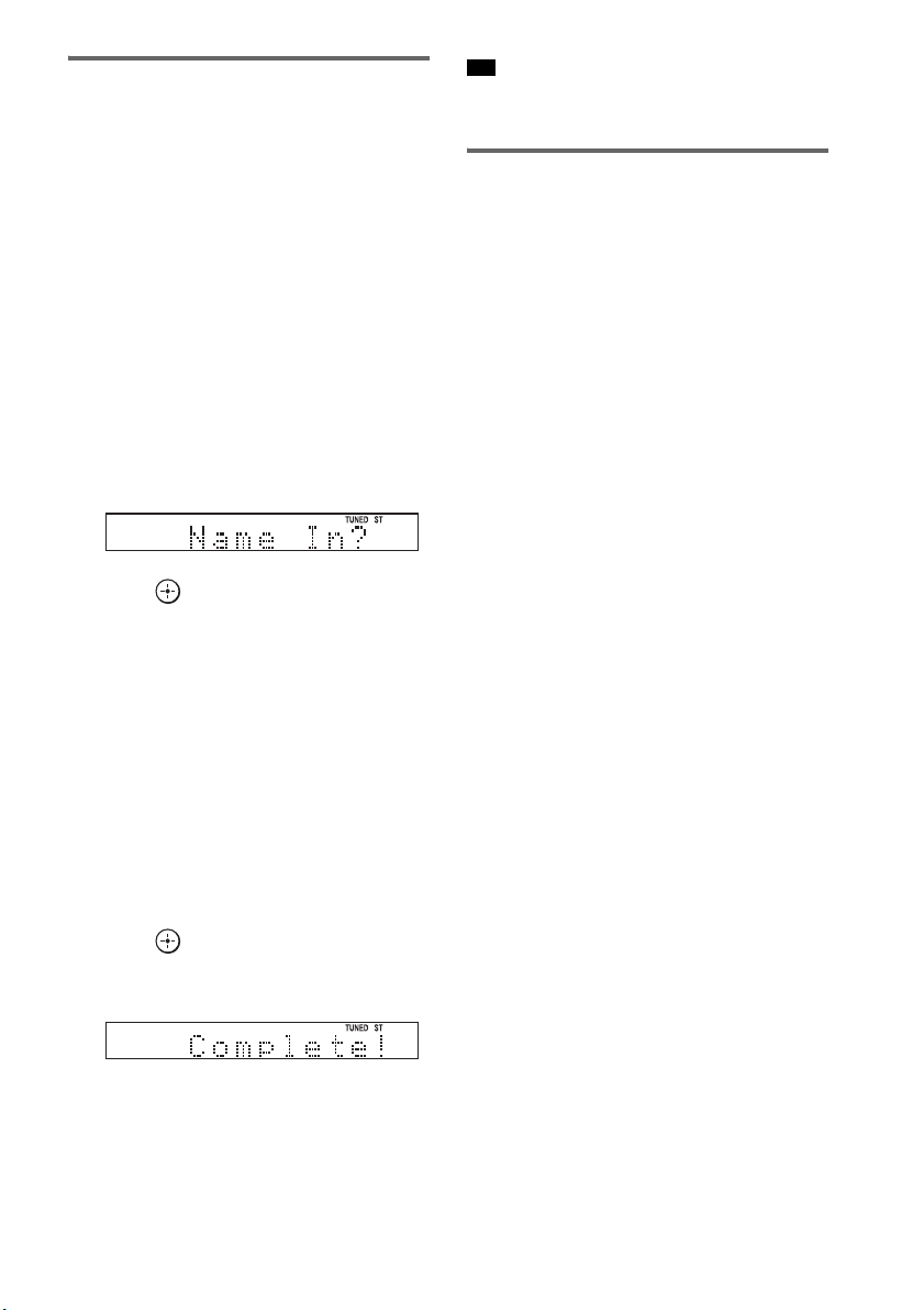
48
GB
Naming preset stations
You can enter a name for preset stations. These
names (for example, “XYZ”) appear in the top
panel display when a station is selected.
Note that no more than one name can be entered
for each preset station.
1 Press TUNER/BAND.
The last received station is tuned in.
You can change “FM” or “AM” by pressing
TUNER/BAND.
2 Press PRESET + or – repeatedly to
select the preset station you want to
create an index name for.
3 Press MENU.
4 Press X/x repeatedly until “Name In?”
appears in the top panel display.
5 Press .
6 Create a name by using C/X/x/c.
Press X/x to select a character, then press c
to move the cursor to the next position.
Letters, numbers, and other symbols can be
input for a radio station name.
If you enter a wrong character
Press C/c repeatedly until the character to
be changed flashes, then press X/x to select
the desired character.
To erase the character, press C/c repeatedly
until the character to be erased flashes, then
press CLEAR.
7 Press .
“Complete!” appears in the top panel
display, and the station name is stored.
8 Press MENU.
• You can check the frequency in the top panel display
by pressing DISPLAY repeatedly (page 48).
Viewing the station name or
frequency in the top panel
display
When the system is set to “FM” or “AM,” you
can check the frequency using the top panel
display.
Press DISPLAY.
Each time you press DISPLAY, the top panel
display changes as shown.
1 Station name*
2 Frequency**
* This is displayed if you have entered a name for a
preset station.
** Returns to the original display when several seconds
have elapsed.
Tip

49
GB
Tuner Functions
What is the Radio Data
System?
The Radio Data System (RDS) is a broadcasting
service that allows radio stations to send
additional information along with the regular
program signal. This tuner offers convenient
RDS features, such as station name display. RDS
is available only for FM stations.*
• RDS may not work properly if the station you are
tuned to is not transmitting the RDS signal properly,
or if the signal strength is weak.
* Not all FM stations provide RDS service, nor do
they provide the same type of services. If you are not
familiar with the RDS system, check with your local
radio stations for details on RDS services in your
area.
Receiving RDS broadcasts
Simply select a station from the FM band.
When you tune in a station that provides RDS
services, the station name* appears in the top
panel display.
* If an RDS broadcast is not received, a station name
will not appear in the top panel display.
• When a station name is displayed, you can check the
frequency by pressing DISPLAY repeatedly.
Using the Radio Data
System (RDS)
(Except for Australian models)
Note
Tip
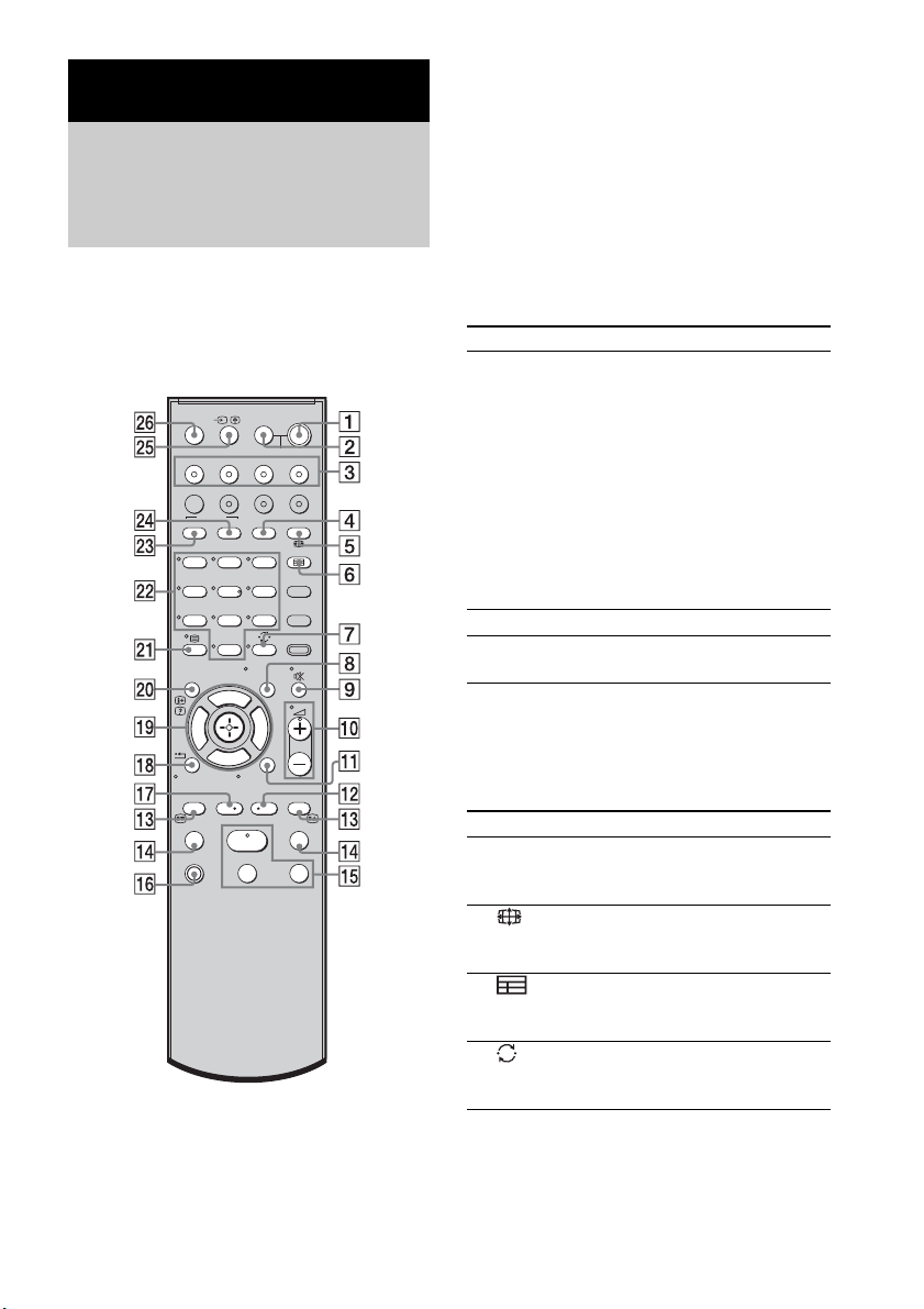
50
GB
You can control connected Sony components
with the remote of this system.
Some functions cannot be selected depending on
the component. In that case, select them using
the remote control of the component.
* The 5, H, and 2 + buttons have a tactile dot. Use
it as a guide during operation.
To control the component
1 Press one of the input buttons 3 (TV,
BD, DVD, or SAT) to select the
component you want to operate.
The component assigned to the selected
input button becomes operable.
2 Referring to the following table, press
the corresponding button for the
operation.
Common operations
To control the TV
Press and hold qh TV (orange) button while
pressing the buttons with an orange dot or orange
printing to control the TV.
Advanced Settings
Controlling the Connected
Sony Components with the
Remote
123
46
78
0
ENTERCLEAR
9
THEATRE
TV
?/1
AV
?/1
TV BD DVD SAT
TOP MENU MENU
BD/DVD
RETURN/EXIT
TV
F1 F2
AMP MENU
DISPLAY
TONE
TUNING - TUNING +
NIGHT
MODE
A/BDIGITALANALOG
DMPORTTUNER/BANDVIDEO
SOUND FIELD
?/1
TV CH -
PRESET -
TV CH +
PRESET +
F
Gg
f
.
HmM
Xx
<
<
>
5
SYSTEM STANDBY
MENU/HOME
TOOLS/
OPTIONS
Remote Button Function
2 TV ?/1
AV ?/1
(on/standby)
Turns on or off the Sony
TV or audio/video
components that the
remote is assigned to
operate.
Press 1
?/1 and 2 TV
?/1/AV ?/1 at the same
time to turn off the system
and all other components
that the remote is assigned
to operate (SYSTEM
STANDBY).
7 ENTER Enters the selection.
ws Number buttons Selects channels and tracks
directly.
Remote Button Function
4 A/B Selects the sound from the
speaker for a stereo or
bilingual broadcast.
5 (Screen mode) Changes the screen format
manually to suit the
broadcast.
6 (Guide) Displays the guide when
you are watching analog or
digital channels.
7
(Previous channel)
Returns to the previous
channel watched (for more
than five seconds).
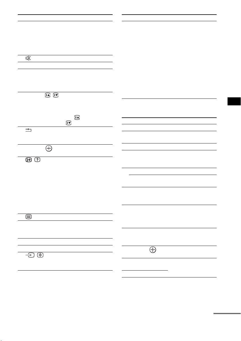
51
GB
Advanced Settings
To control the DVD recorder/Blu-
ray Disc recorder
8 TOOLS/
OPTIONS
Enables you to access
various viewing options
and change/make
adjustments according to
the source and screen
format.
9 (Muting) Turns off the sound.
q; 2 +/– Adjusts the volume.
qa MENU/HOME Allows you to select
channels or input sources
and change the settings for
your TV.
qd PROG +/–/ / In TV mode: Selects the
next (+) or previous (-)
channel.
In Text mode: Selects the
next ( ) or previous
( ) page.
qk RETURN/EXIT Returns to the previous
screen of any displayed
menu.
ql C, X, x, c, Selects a menu item and
enters the selection.
w; / (Info/Text
reveal)
In digital mode: Displays
brief details of the program
currently being watched.
In analogue mode:
Displays information such
as current channel number
and screen format.
In Text mode: Reveals
hidden information (e.g.
answers to a quiz).
wa (Text) Displays Text.
ws Number buttons Selects channels. Press 7
ENTER to change
channels immediately.
wd ANALOG Changes to analog mode.
wf DIGITAL Changes to digital mode.
wg / (Input
select/Text hold)
In TV mode: Selects input.
In Analogue Text mode:
Holds the current page.
Remote Button Function
wh THEATRE Automatically sets the
optimal picture settings for
watching movies, when
you connect a Sony TV
which is compatible with
the THEATRE button.
Also, the audio is
automatically switched to
the audio output of this
system when you connect
the TV and the system with
HDMI connection, and the
Control for HDMI function
is set to on.
Remote Button Function
4 F1 Selects the HDD.
5 F2 Selects the Blu-ray Disc/
DVD.
qa MENU/HOME Displays the MENU.
qs •
, Jumps forward while
viewing recorded
programs.
qd . Skips chapters.
> Skips forward to the next
available chapter.
qf m/M To fast reverse or to fast
forward the disc when
pressed during playback.
qg H (playback)/X
(pause, press again to
resume normal
playback)/x (stop)
Play mode buttons.
qj
< • Jumps backward while
viewing live or recorded
programs.
ql C, X, x, c, Selects a menu item and
enters the selection.
wd BD/DVD
TOP MENU
Displays the top menu/disc
menu.
wf BD/DVD MENU
Remote Button Function
continued
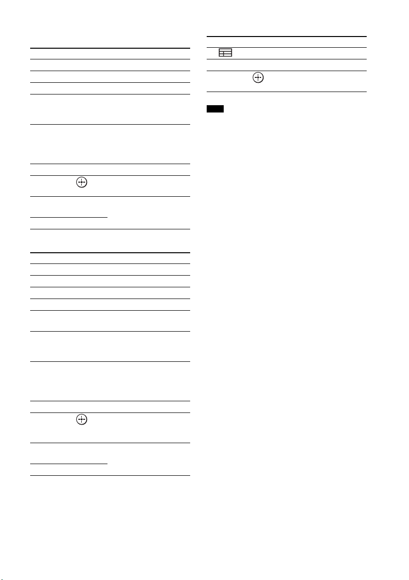
52
GB
To control the DVD player/Blu-ray
Disc player
To control the HDD/DVD COMBO
To control the SAT
• The above explanations are intended to serve as an
example only. Depending on the component, the
above operations may not be possible, or may operate
differently than described.
Remote Button Function
qa MENU/HOME Displays the MENU.
qs •
, Jumps forward.
qd ./> Skips chapters.
qf m/M To fast reverse or to fast
forward the disc when
pressed during playback.
qg H (playback)/X
(pause, press again to
resume normal
playback)/x (stop)
Play mode buttons.
qj
< • Jumps backward.
ql C, X, x, c, Selects a menu item and
enters the selection.
wd BD/DVD
TOP MENU
Displays the top menu/disc
menu.
wf BD/DVD MENU
Remote Button Function
4 F1 Selects the HDD.
5 F2 Selects the DVD.
qa MENU/HOME Displays the MENU.
qs •
, Advance.
qd ./> Specifies the previous/next
chapter/track.
qf m/M To fast reverse or to fast
forward the disc when
pressed during playback.
qg H (playback)/X
(pause, press again to
resume normal
playback)/x (stop)
Play mode buttons.
qj
< • Changes to replay mode.
ql C, X, x, c, Moves the highlight
(cursor) and selects the
item.
wd BD/DVD
TOP MENU
Displays the top menu/disc
menu.
wf BD/DVD MENU
Remote Button Function
6 (Guide) Displays the guide menu.
qa MENU/HOME Displays the MENU.
ql C, X, x, c, Selects a menu item and
enters the selection.
Note
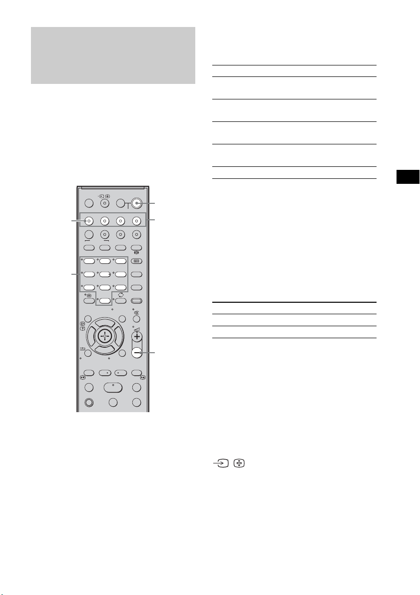
53
GB
Advanced Settings
You can change the factory settings of the input
buttons to suit the components in your system.
For example, if you connect a Blu-ray Disc
player to the DVD jack on the system, you can
set the DVD button on this remote to control the
Blu-ray Disc player.
You cannot assign any component other than a
TV to the TV (white) button of the remote.
1 Hold down the input button you want to
change the assignment of.
Example: Hold down DVD.
2 Referring to the following table, press
the corresponding button for the
category you want.
Example: Press 3.
Now you can use the DVD button to control
the Blu-ray Disc player.
Categories and the
corresponding buttons for BD,
DVD, and SAT
* The default setting of the DVD button.
Sony DVD recorders are operated with a DVD1 or
DVD3 setting. For details, refer to the operating
instructions of the DVD recorders.
** The default setting of the BD button.
For details on the BD1 or BD3 setting, refer to the
operating instructions of the Blu-ray Disc player or
Blu-ray Disc recorder.
*** The default setting of the SAT button.
Categories and the
corresponding buttons for TV
* The default setting of the TV (white) button.
When this setting is selected, the audio input of the
TV is switched and the image from the TV tuner is
displayed on the TV screen automatically by
pressing the TV (white) button.
** When this setting is selected, the audio input of the
TV is switched automatically by pressing the TV
(white) button.
To clear all remote button
assignments
Press and hold 2 –, ?/1, and then press
/ . The remote is reset to its factory
settings.
Changing the Input Button
Assignments of the
Remote
123
46
78
0
ENTERCLEAR
9
THEATRE
TV
?/1
AV
?/1
TV BD DVD SAT
TOP MENU MENU
BD/DVD
RETURN/EXIT
TV
F1 F2
AMP MENU
DISPLAY
TONE
TUNING - TUNING +
NIGHT
MODE
A/BDIGITALANALOG
DMPORTTUNER/BANDVIDEO
SOUND FIELD
?/1
TV CH -
PRESET -
TV CH +
PRESET +
F
Gg
f
.
HmM
Xx
<
<
>
5
SYSTEM STANDBY
MENU/HOME
TOOLS/
OPTIONS
2 –
Number
buttons
Input
buttons
TV
(white)
?/1
Categories Press
DVD player
(command mode DVD1)
1
DVD recorder
(command mode DVD3)*
2
Blu-ray Disc player
(command mode BD1)**
3
Blu-ray Disc recorder
(command mode BD3)
4
Euro Digital Satellite Receiver *** 7
Categories Press
TV* 5
TV** 6
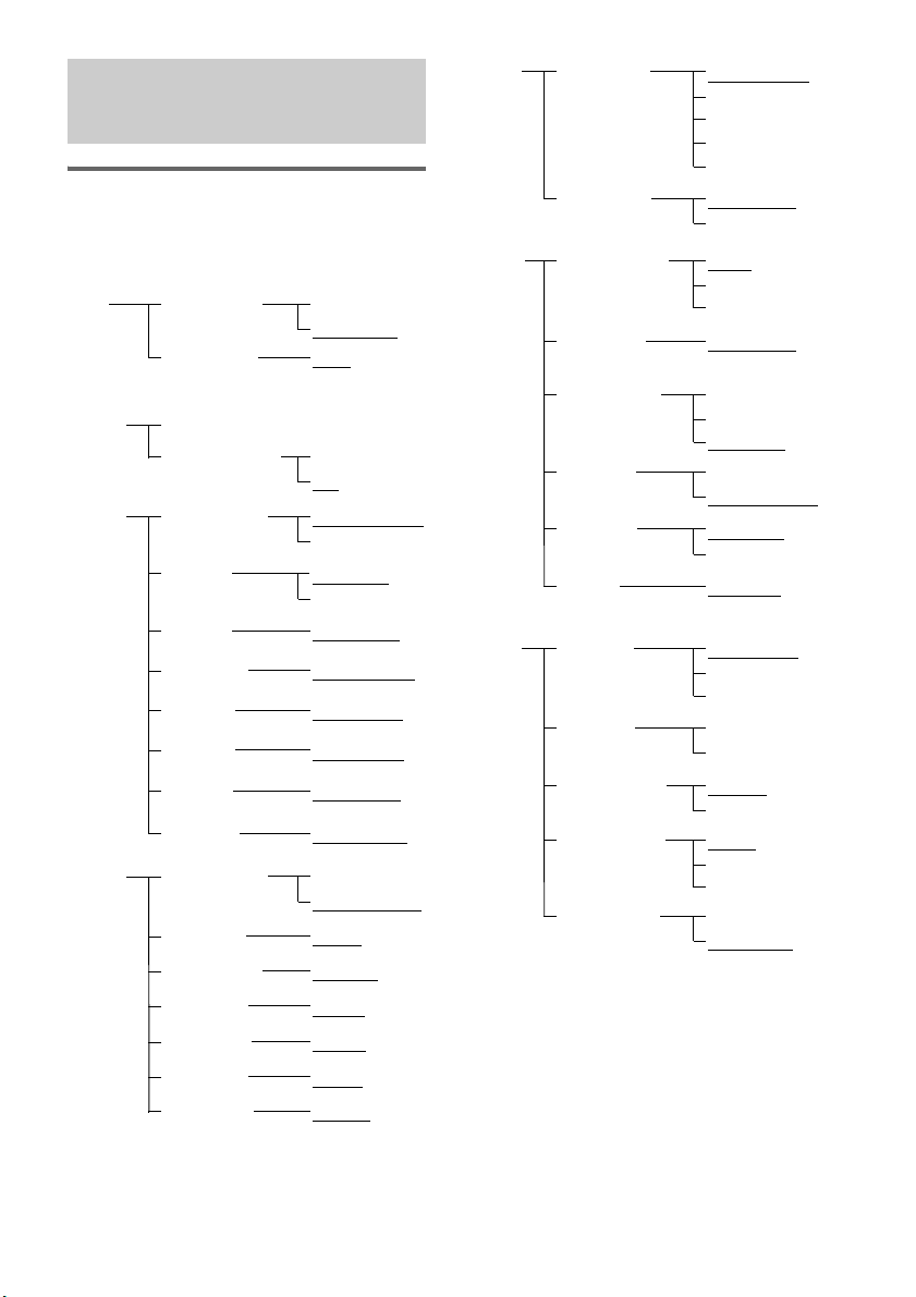
54
GB
Using the AMP menu
You can set the following items with AMP
MENU on the remote.
The default settings are underlined.
1)
See ““BRAVIA” Sync features” (page 41).
2)
This setting appears only when “CTRL: HDMI” is
set to “CTRL ON.”
3)
See “Step 6: Calibrating the Appropriate Settings
Automatically” (page 24). “A. CAL CLEAR”
setting appears only when the result of the Auto
Calibration is saved.
4)
This setting is only for the optical and coaxial input
signals.
Settings and Adjustments
Using the Amplifier Menu
CTRL ON
CTRL OFF
CTRL: HDMI
MAX, 49,
48…..2, 1,
MIN
VOL LIMIT
2)
SET
HDMI
1)
FL 3m 0cmFL DIST
CENTER YES
CENTER NO
CENTER SP
SP
SETUP
SUR YES
SUR NO
SUR SP
CNT 3m 0cm
CNT DIST
FR 3m 0cm
FR DIST
SR 3m 0cm
SR DIST
SL 3m 0cm
SL DIST
SW 3m 0cmSW DIST
FL 0.0FL LEVEL
T. TONE ON
T. TONE OFF
TEST TONE
LEVEL
CNT 0.0
CNT LEVEL
FR 0.0
FR LEVEL
SR 0.0
SR LEVEL
SL 0.0
SL LEVEL
SW 0.0SW LEVEL
A. CAL START
YES
NO
A. CAL CLEAR
A. CAL
MENU
3)
SYNC OFF,
1, 2, …..20
A/V SYNC
4)
ANALOG VD
ANALOG TV
A. ASSIGN
AUDIO
ANALOG SAT
ANALOG DVD
ANALOG BD
COAX SAT
COAX DVD
D. ASSIGN
MAIN
SUB
DUAL MONO
MAIN+SUB
DRC MAX
DRC
STD
AUDIO DRC
DRC OFF
SLEEP OFF, 10M,
20M, …..90M
SLEEP
DIMMER ON
DIMMER OFF
DIMMER
CUST-
OMIZE
DSPL ON
DSPL OFF
DISPLAY
START
CONDITION
PAIRING
S-AIR
SET
5)
S-AIR ID: A
S-AIR ID: B
S-AIR ID
S-AIR ID: C
PARTY
SEPARATE
S-AIR MODE
AUTO
ON
RF CHANGE
OFF
STBY ON
STBY OFF
S-AIR STBY
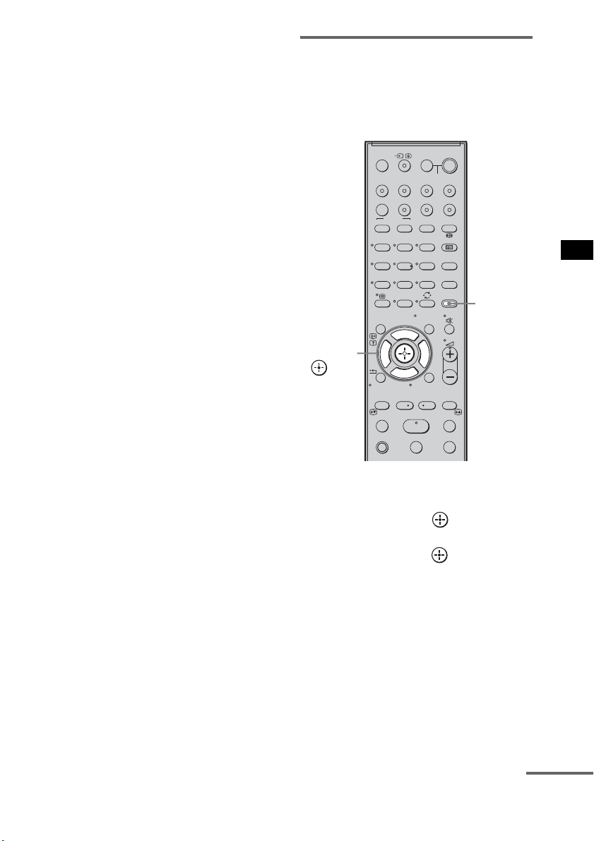
55
GB
Advanced Settings
5)
This setting appears only when you insert the S-AIR
transmitter (not supplied).
1 Press AMP MENU to turn on the AMP
menu.
2 Press C/X/x/c repeatedly to select the
item and the setting.
3 Press AMP MENU to turn off the AMP
menu.
The following pages show details for each
setting.
Setting the speaker
connection
To obtain the best possible surround sound, you
can set the connection of the center and surround
speakers.
1 Press AMP MENU.
2 Press x/X repeatedly until “SP SETUP”
appears, then press or c.
3 Press x/X repeatedly to select the
speaker, then press or c.
• CENTER SP: selects the center speaker.
• SUR SP: selects the surround speakers.
4 Press x/X to select the setting.
• CENTER (SUR) YES: selects when you
connect the speaker(s).
• CENTER (SUR) NO: selects when you do
not connect the speaker(s).
5 Press AMP MENU.
The AMP menu turns off.
123
46
78
0
ENTERCLEAR
9
THEATRE
TV
?/1
AV
?/1
TV BD DVD SAT
TOP MENU MENU
BD/DVD
RETURN/EXIT
TV
F1 F2
AMP MENU
DISPLAY
TONE
TUNING - TUNING +
NIGHT
MODE
A/BDIGITALANALOG
DMPORTTUNER/BANDVIDEO
SOUND FIELD
?/1
TV CH -
PRESET -
TV CH +
PRESET +
F
Gg
f
.
HmM
Xx
<
<
>
5
SYSTEM STANDBY
MENU/HOME
TOOLS/
OPTIONS
AMP
MENU
C, X, x, c,
continued
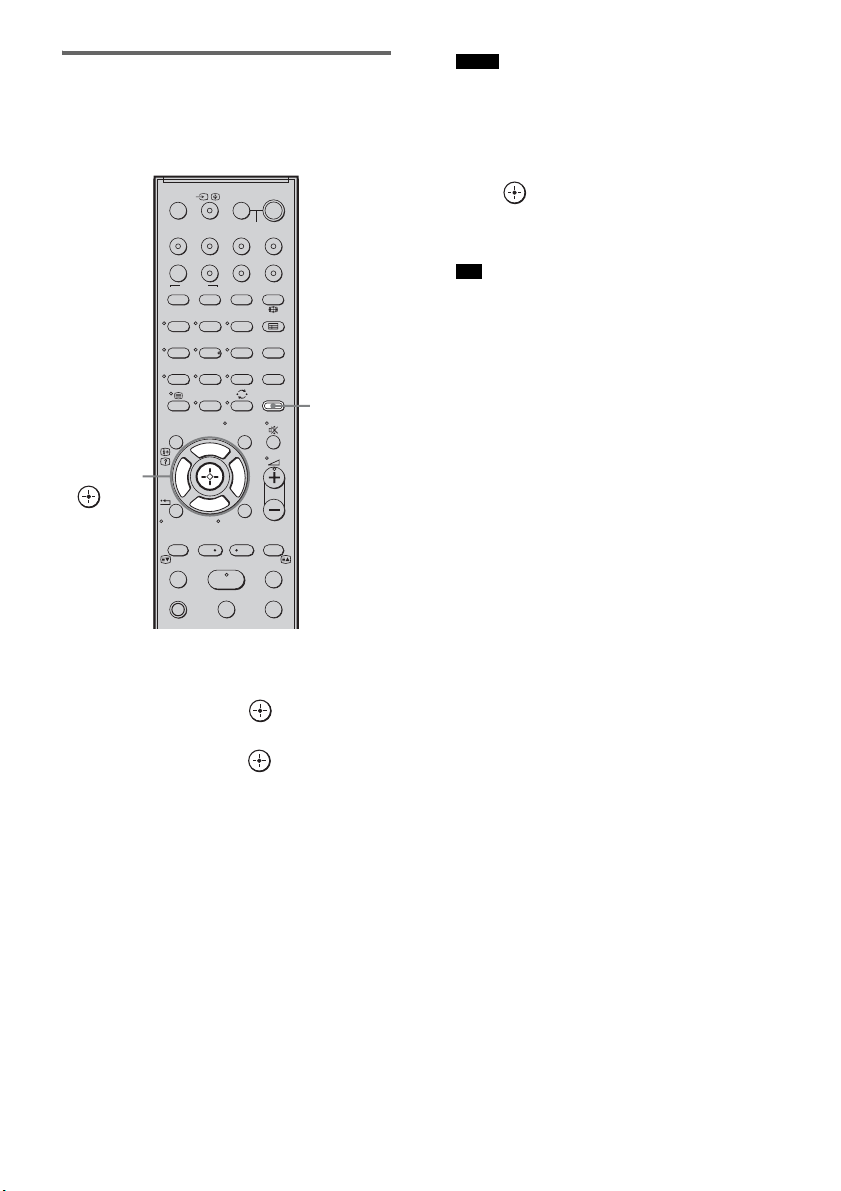
56
GB
Setting the speaker distance
To obtain the best possible surround sound, you
can set the speaker distance from your listening
position.
1 Press AMP MENU.
2 Press x/X repeatedly until “SP SETUP”
appears, then press or c.
3 Press x/X repeatedly to select the
speaker, then press or c.
• FL DIST: adjusts the front left speaker
distance.
• CNT DIST: adjusts the center speaker
distance.
• FR DIST: adjusts the front right speaker
distance.
• SR DIST: adjusts the surround right
speaker distance.
• SL DIST: adjusts the surround left speaker
distance.
• SW DIST: adjusts the subwoofer distance.
• “CNT DIST” does not appear when you set
“CENTER NO” in the “SP SETUP” setting.
• “SR DIST” and “SL DIST” do not appear when
you set “SUR NO” in the “SP SETUP” setting.
4 Press x/X to set the parameter, then
press or C.
Default setting: 3m 0cm.
The adjustment range is 0m 0cm to 7m 0cm.
• When the result of the Auto Calibration is saved,
you can adjust the speakers distance in 1 cm
steps.
If the result of the Auto Calibration is not saved,
you can adjust the speakers distance in 10 cm
steps.
5 Repeat step 3 and 4.
6 Press AMP MENU.
The AMP menu turns off.
123
46
78
0
ENTERCLEAR
9
THEATRE
TV
?/1
AV
?/1
TV BD DVD SAT
TOP MENU MENU
BD/DVD
RETURN/EXIT
TV
F1 F2
AMP MENU
DISPLAY
TONE
TUNING - TUNING +
NIGHT
MODE
A/BDIGITALANALOG
DMPORTTUNER/BANDVIDEO
SOUND FIELD
?/1
TV CH -
PRESET -
TV CH +
PRESET +
F
Gg
f
.
HmM
Xx
<
<
>
5
SYSTEM STANDBY
MENU/HOME
TOOLS/
OPTIONS
AMP
MENU
C, X, x, c,
Notes
Tip
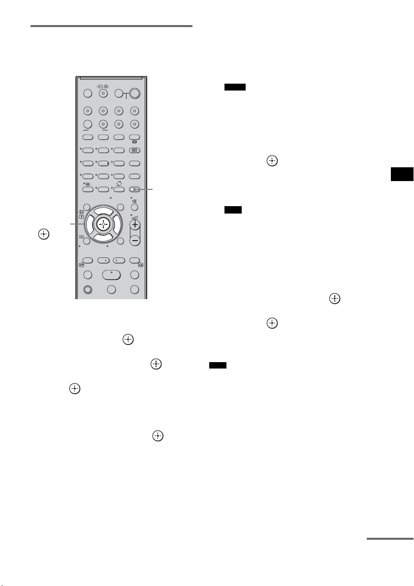
57
GB
Advanced Settings
Setting the speaker level
You can use the test tone to adjust the level and
the balance of the speakers.
1 Press AMP MENU.
2 Press x/X repeatedly until “LEVEL”
appears, then press or c.
3 Press x/X repeatedly until “TEST
TONE” appears, then press or c.
4 Press X/x to select “T. TONE ON,” then
press .
The test tone is emitted from each speaker in
sequence.
5 Press x/X repeatedly to select the
desired speaker, then press or c.
The test tone is emitted from only the
speaker that is being adjusted.
• FL LEVEL: adjusts the front left speaker
level.
• CNT LEVEL: adjusts the center speaker
level.
• FR LEVEL: adjusts the front right speaker
level.
• SR LEVEL: adjusts the surround right
speaker level.
• SL LEVEL: adjusts the surround left
speaker level.
• SW LEVEL: adjusts the subwoofer level.
• “CNT LEVEL” does not appear when you set
“CENTER NO” in the “SP SETUP” setting.
• “SR LEVEL” and “SL LEVEL” do not appear
when you set “SUR NO” in the “SP SETUP”
setting.
6 Press x/X to adjust the speaker level,
then press or c.
Default setting: 0.0 (dB)
You can adjust from –6.0 (dB) to +6.0 (dB)
in 0.5 (dB) steps.
• If you do not adjust for a certain period, the test
tone is emitted from the next speaker in
sequence.
7 Repeat step 5 and 6 to adjust the
speaker level.
8 After you have finished making
adjustments, press
x/X until “TEST
TONE” appears, then press or c.
9 Press X/x to select “T. TONE OFF,”
then press .
10Press AMP MENU.
The AMP menu turns off.
• The test tone signals are not output from the HDMI
OUT jack.
123
46
78
0
ENTERCLEAR
9
THEATRE
TV
?/1
AV
?/1
TV BD DVD SAT
TOP MENU MENU
BD/DVD
RETURN/EXIT
TV
F1 F2
AMP MENU
DISPLAY
TONE
TUNING - TUNING +
NIGHT
MODE
A/BDIGITALANALOG
DMPORTTUNER/BANDVIDEO
SOUND FIELD
?/1
TV CH -
PRESET -
TV CH +
PRESET +
F
Gg
f
.
HmM
Xx
<
<
>
5
SYSTEM STANDBY
MENU/HOME
TOOLS/
OPTIONS
AMP
MENU
C, X, x, c,
Notes
Note
Note
continued
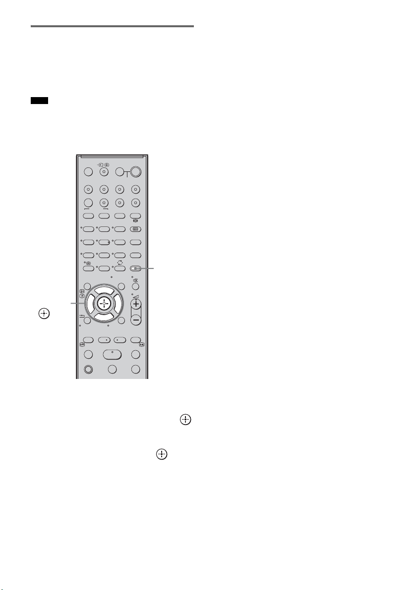
58
GB
Enjoying multiplex broadcast
sound (DUAL MONO)
You can enjoy multiplex broadcast sound when
the system receives an AC-3 multiplex broadcast
signal.
• To receive AC-3 signal, you need to connect a digital
satellite tuner to the system with an optical cable or
coaxial cable, and set the digital output mode of the
digital satellite tuner to AC-3.
1 Press AMP MENU.
2 Press x/X repeatedly until
“CUSTOMIZE” appears, then press
or c.
3 Press x/X repeatedly until “DUAL
MONO”
appears, then press or c.
4 Press x/X to select the sound you want.
• MAIN: plays back only the main
channel.
• SUB: plays back only the sub
channel.
• MAIN+SUB: main sound is output from
the left speaker and sub
sound is output from the
right speaker.
5 Press AMP MENU.
The AMP menu turns off.
Note
123
46
78
0
ENTERCLEAR
9
THEATRE
TV
?/1
AV
?/1
TV BD DVD SAT
TOP MENU MENU
BD/DVD
RETURN/EXIT
TV
F1 F2
AMP MENU
DISPLAY
TONE
TUNING - TUNING +
NIGHT
MODE
A/BDIGITALANALOG
DMPORTTUNER/BANDVIDEO
SOUND FIELD
?/1
TV CH -
PRESET -
TV CH +
PRESET +
F
Gg
f
.
HmM
Xx
<
<
>
5
SYSTEM STANDBY
MENU/HOME
TOOLS/
OPTIONS
AMP
MENU
C, X, x, c,
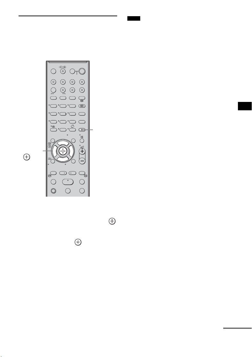
59
GB
Advanced Settings
Adjusting the delay between
the sound and the image (A/V
SYNC)
You can delay the sound using this function
when the image is slower than the sound.
1 Press AMP MENU.
2 Press x/X repeatedly until
“CUSTOMIZE” appears, then press
or c.
3 Press X/x repeatedly until “A/V SYNC”
appears, then press or c.
4 Press X/x to set the parameter.
• SYNC OFF: does not adjust.
• SYNC 1 – 20: adjusts from 1 (10 ms) to 20
(200 ms) in 1 (10 ms) steps.
5 Press AMP MENU.
The AMP menu turns off.
• You may not be able to adjust the delay between
sound and image perfectly using this function.
• This function is useful only for Dolby Digital, DTS
and Linear PCM (2ch) input by optical and coaxial
audio input signals.
123
46
78
0
ENTERCLEAR
9
THEATRE
TV
?/1
AV
?/1
TV BD DVD SAT
TOP MENU MENU
BD/DVD
RETURN/EXIT
TV
F1 F2
AMP MENU
DISPLAY
TONE
TUNING - TUNING +
NIGHT
MODE
A/BDIGITALANALOG
DMPORTTUNER/BANDVIDEO
SOUND FIELD
?/1
TV CH -
PRESET -
TV CH +
PRESET +
F
Gg
f
.
HmM
Xx
<
<
>
5
SYSTEM STANDBY
MENU/HOME
TOOLS/
OPTIONS
AMP
MENU
C, X, x, c,
Notes
continued
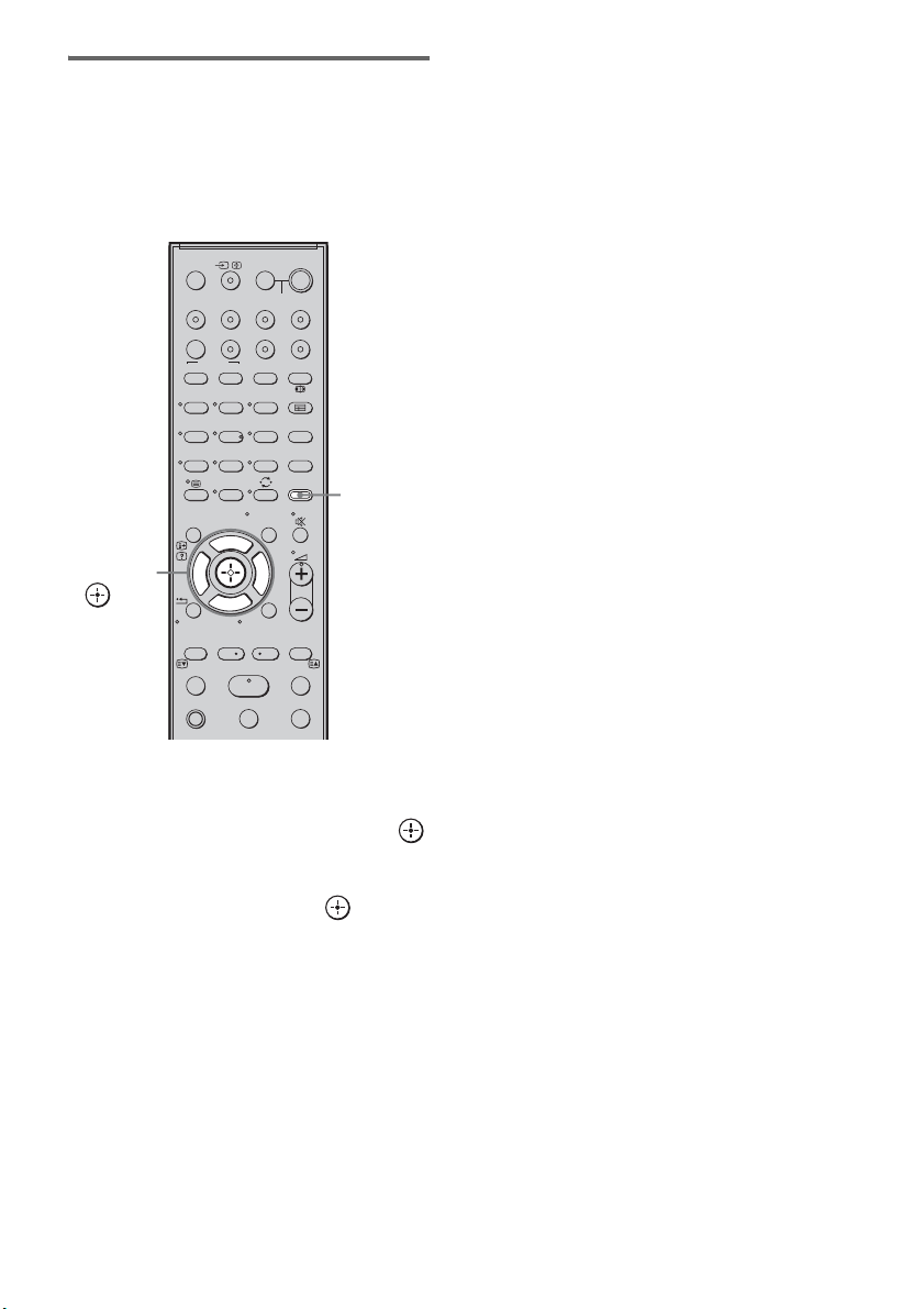
60
GB
Enjoying Dolby Digital sound
at low volume (AUDIO DRC)
You can compress the dynamic range of the
sound track. AUDIO DRC is useful for watching
movies at low volume. AUDIO DRC only
applies to Dolby Digital sources.
1 Press AMP MENU.
2 Press x/X repeatedly until
“CUSTOMIZE” appears, then press
or c.
3 Press x/X repeatedly until “AUDIO
DRC” appears, then press or c.
4 Press x/X to select the setting.
• DRC MAX: compresses dynamic range
fully.
• DRC STD: reproduces the sound track
with the kind of dynamic
range that the recording
engineer intended.
• DRC OFF: no compression of dynamic
range.
5 Press AMP MENU.
The AMP menu turns off.
123
46
78
0
ENTERCLEAR
9
THEATRE
TV
?/1
AV
?/1
TV BD DVD SAT
TOP MENU MENU
BD/DVD
RETURN/EXIT
TV
F1 F2
AMP MENU
DISPLAY
TONE
TUNING - TUNING +
NIGHT
MODE
A/BDIGITALANALOG
DMPORTTUNER/BANDVIDEO
SOUND FIELD
?/1
TV CH -
PRESET -
TV CH +
PRESET +
F
Gg
f
.
HmM
Xx
<
<
>
5
SYSTEM STANDBY
MENU/HOME
TOOLS/
OPTIONS
AMP
MENU
C, X, x, c,
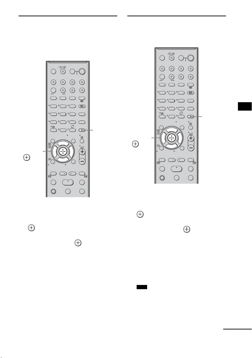
61
GB
Advanced Settings
Changing the brightness of
the top panel display
(DIMMER)
The brightness of the top panel display can be set
to one of 2 levels.
1 Press AMP MENU.
2 Press x/X repeatedly until
“CUSTOMIZE” appears, then press
or c.
3 Press X/x repeatedly until “DIMMER”
appears, then press or c.
4 Press X/x to select the brightness of
the top panel display.
• DIMMER ON:low lighting.
• DIMMER OFF:bright lighting.
5 Press AMP MENU.
The AMP menu turns off.
Changing the display setting
(DISPLAY)
You can change the display setting.
1 Press AMP MENU.
2 Press x/X repeatedly until
“CUSTOMIZE” appears, then press
or c.
3 Press x/X repeatedly until “DISPLAY”
appears, then press or c.
4 Press x/X to select the setting of the
top panel display.
• DSPL ON: the display appears all the
time.
• DSPL OFF: the display appears for a
moment when you operate
the system.
• The display appears all the time when the muting
or protection function is working, even if you set
the “DISPLAY” to “DSPL OFF.”
123
46
78
0
ENTERCLEAR
9
THEATRE
TV
?/1
AV
?/1
TV BD DVD SAT
TOP MENU MENU
BD/DVD
RETURN/EXIT
TV
F1 F2
AMP MENU
DISPLAY
TONE
TUNING - TUNING +
NIGHT
MODE
A/BDIGITALANALOG
DMPORTTUNER/BANDVIDEO
SOUND FIELD
?/1
TV CH -
PRESET -
TV CH +
PRESET +
F
Gg
f
.
HmM
Xx
<
<
>
5
SYSTEM STANDBY
MENU/HOME
TOOLS/
OPTIONS
AMP
MENU
C, X, x, c,
Note
123
46
78
0
ENTERCLEAR
9
THEATRE
TV
?/1
AV
?/1
TV BD DVD SAT
TOP MENU MENU
BD/DVD
RETURN/EXIT
TV
F1 F2
AMP MENU
DISPLAY
TONE
TUNING - TUNING +
NIGHT
MODE
A/BDIGITALANALOG
DMPORTTUNER/BANDVIDEO
SOUND FIELD
?/1
TV CH -
PRESET -
TV CH +
PRESET +
F
Gg
f
.
HmM
Xx
<
<
>
5
SYSTEM STANDBY
MENU/HOME
TOOLS/
OPTIONS
AMP
MENU
C, X, x, c,
continued

62
GB
5 Press AMP MENU.
The AMP menu turns off.
Using the sleep timer
(SLEEP)
You can set the system to turn off at a preset time
when you sleep listening to music. You can
preset the time in 10 minutes decrements.
1 Press AMP MENU.
2 Press x/X repeatedly until
“CUSTOMIZE” appears, then press
or c.
3 Press x/X repeatedly until “SLEEP”
appears, then press or c.
4 Press x/X to select the preset time.
The minutes display (the remaining time)
changes as follows:
5 Press AMP MENU.
The AMP menu turns off.
123
46
78
0
ENTERCLEAR
9
THEATRE
TV
?/1
AV
?/1
TV BD DVD SAT
TOP MENU MENU
BD/DVD
RETURN/EXIT
TV
F1 F2
AMP MENU
DISPLAY
TONE
TUNING - TUNING +
NIGHT
MODE
A/BDIGITALANALOG
DMPORTTUNER/BANDVIDEO
SOUND FIELD
?/1
TV CH -
PRESET -
TV CH +
PRESET +
F
Gg
f
.
HmM
Xx
<
<
>
5
SYSTEM STANDBY
MENU/HOME
TOOLS/
OPTIONS
AMP
MENU
C, X, x, c,
OFF y 10M y 20M
YY
90M y 80M ..... 30M
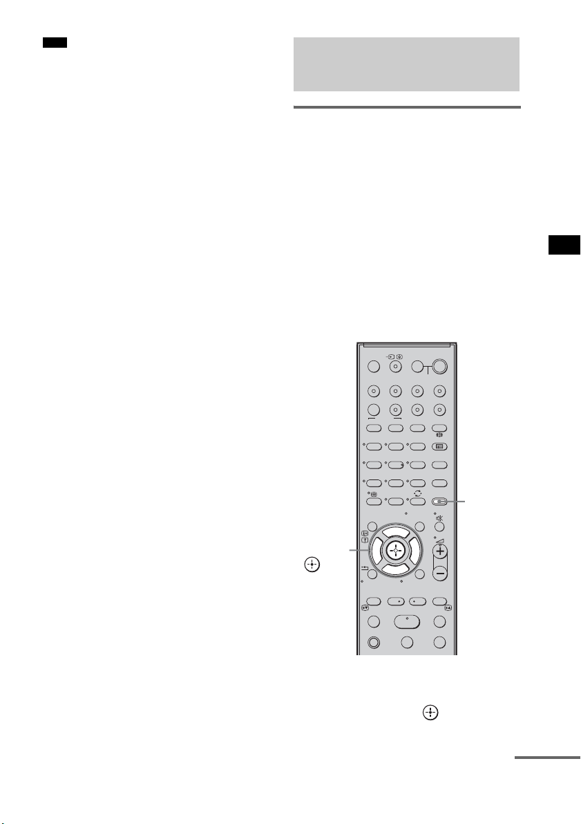
63
GB
Advanced Settings
• This function is only for this system, not for the
connected TV or other components.
Reassigning the analog audio
input
You can reassign an audio input that has audio
(analog) signal to the “TV,” “BD,” “DVD,”
“SAT,” or “VIDEO” function, if it is not being
used.
For example, to output the audio source for DVD
player using the AUDIO IN ASSIGNABLE
jacks on the subwoofer:
• Connect the analog output jacks of the DVD
player to the AUDIO IN ASSIGNABLE jacks
on the subwoofer.
• Assign “DVD” function to the “ANALOG
DVD” in the “A. ASSIGN” setting.
1 Press AMP MENU.
2 Press x/X repeatedly until “AUDIO”
appears, then press or c.
Note
Reassigning the audio
inputs
123
46
78
0
ENTERCLEAR
9
THEATRE
TV
?/1
AV
?/1
TV BD DVD SAT
TOP MENU MENU
BD/DVD
RETURN/EXIT
TV
F1 F2
AMP MENU
DISPLAY
TONE
TUNING - TUNING +
NIGHT
MODE
A/BDIGITALANALOG
DMPORTTUNER/BANDVIDEO
SOUND FIELD
?/1
TV CH -
PRESET -
TV CH +
PRESET +
F
Gg
f
.
HmM
Xx
<
<
>
5
SYSTEM STANDBY
MENU/HOME
TOOLS/
OPTIONS
AMP
MENU
C, X, x, c,
continued
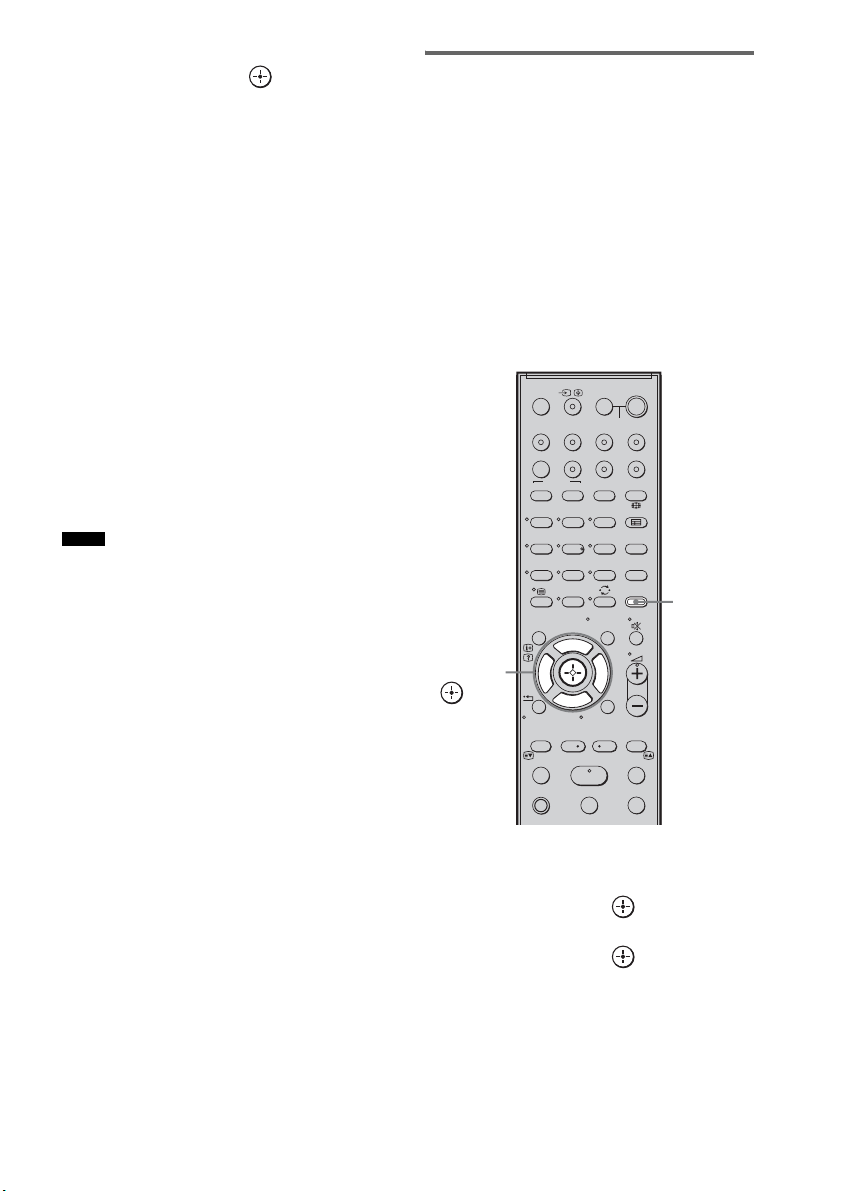
64
GB
3 Press x/X repeatedly until “A. ASSIGN”
appears, then press or c.
4 Press x/X to select the audio input you
want to reassign.
• ANALOG VD: reassigns the analog
audio input to the
“VIDEO” function.
• ANALOG TV: reassigns the analog
audio input to the “TV”
function.
• ANALOG SAT: reassigns the analog
audio input to the “SAT”
function.
• ANALOG DVD:reassigns the analog
audio input to the
“DVD” function.
• ANALOG BD: reassigns the analog
audio input to the “BD”
function.
5 Press AMP MENU.
The AMP menu turns off.
• When images of an audio component are output, the
sound may not be output. In this case, check the
following:
– Confirm the audio analog input jacks correspond
with the function.
– Reassign the function.
• You cannot use the analog audio input for the original
input if it has been reassigned to another input.
• You cannot reassign the analog audio input to the
“TUNER/BAND” and “DMPORT” function.
Reassigning the digital audio
input
You can reassign an audio input that has coaxial
(digital) signal to the “DVD” or “SAT” function,
if either one function is not being used.
For example, to output the audio source for DVD
player using the ASSIGNABLE COAXIAL
SAT IN jack on the subwoofer:
• Connect the coaxial output jack of the DVD
player to the ASSIGNABLE COAXIAL SAT
IN jack on the subwoofer.
• Assign the “DVD” function to “COAX DVD”
in the “D. ASSIGN” setting.
1 Press AMP MENU.
2 Press x/X repeatedly until “AUDIO”
appears, then press or c.
3 Press x/X repeatedly until “D. ASSIGN”
appears, then press or c.
Notes
123
46
78
0
ENTERCLEAR
9
THEATRE
TV
?/1
AV
?/1
TV BD DVD SAT
TOP MENU MENU
BD/DVD
RETURN/EXIT
TV
F1 F2
AMP MENU
DISPLAY
TONE
TUNING - TUNING +
NIGHT
MODE
A/BDIGITALANALOG
DMPORTTUNER/BANDVIDEO
SOUND FIELD
?/1
TV CH -
PRESET -
TV CH +
PRESET +
F
Gg
f
.
HmM
Xx
<
<
>
5
SYSTEM STANDBY
MENU/HOME
TOOLS/
OPTIONS
AMP
MENU
C, X, x, c,
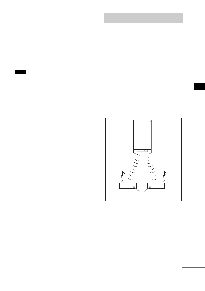
65
GB
Advanced Settings
4 Press x/X to select the audio input you
want to reassign.
• COAX SAT: reassigns the coaxial audio
input to the “SAT”
function.
• COAX DVD: reassigns the coaxial audio
input to the “DVD”
function.
5 Press AMP MENU.
The AMP menu turns off.
• You cannot reassign several digital audio inputs to the
same input.
• You cannot use the digital audio input for the original
input if it has been reassigned to another input.
• You cannot reassign the digital audio input to the
“TV,” “BD,” “VIDEO,” “TUNER/BAND,” or
“DMPORT” function.
About S-AIR products
The system is compatible with the S-AIR
function, which allows sound transmission
between the subwoofer and S-AIR product (not
supplied).
When you purchase the S-AIR product, you need
to perform the following settings to establish the
sound transmission.
There are two types of S-AIR product.
• S-AIR main unit (this subwoofer): This is for
transmitting sound. You can use up to three
S-AIR main units. (The number of usable
S-AIR main units depends on the use
environment.)
• S-AIR sub unit: This is for receiving sound.
Notes
Using an S-AIR Product
S-AIR
main unit
S-AIR sub unit
continued
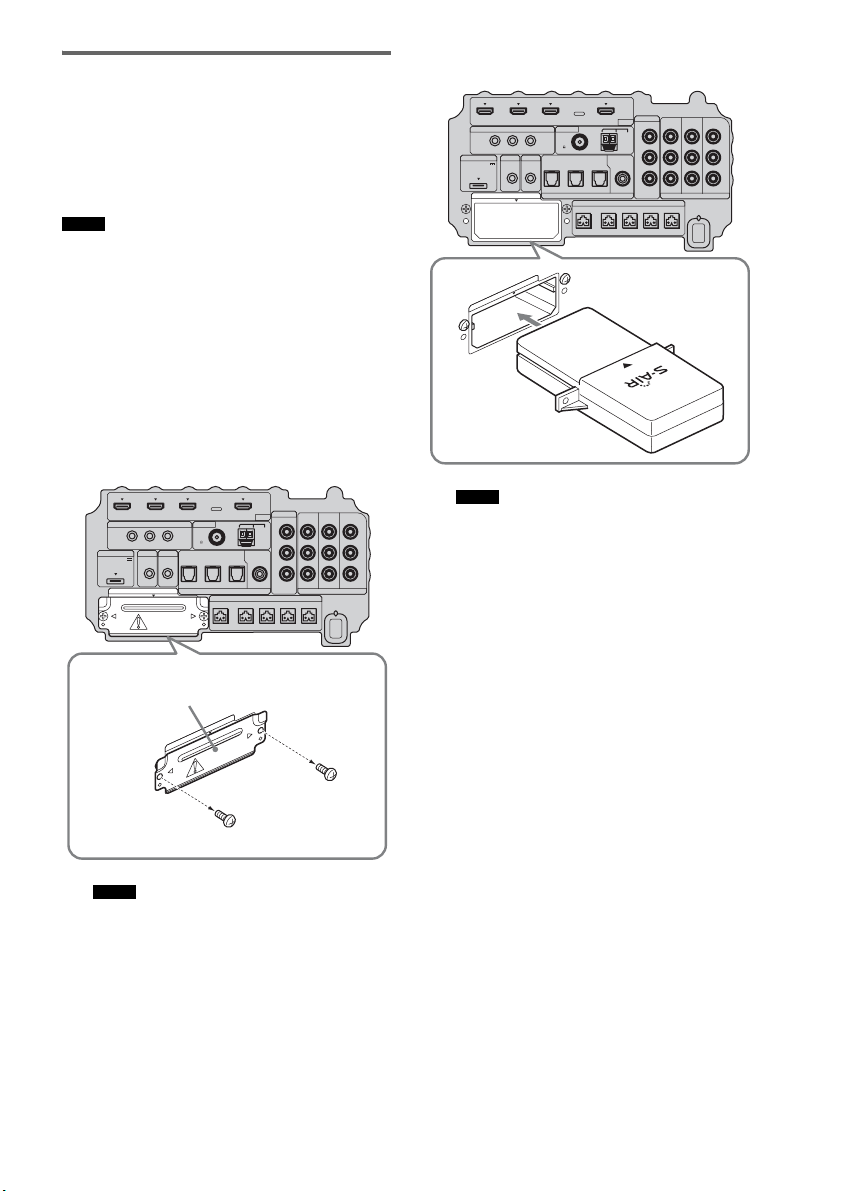
66
GB
Inserting the wireless
transmitter/transceiver
To make use of the S-AIR function, you need to
insert the wireless transmitter (not supplied) into
the subwoofer and the wireless transceiver (not
supplied) into the S-AIR product.
• When you insert the wireless transmitter/transceiver,
make sure that the AC power cord (mains lead) is not
connected to a wall outlet (mains).
• Do not touch the terminals of the wireless transmitter/
transceiver.
To insert the wireless transmitter
into the subwoofer
1 Remove the screws and detach the slot
cover.
• Remove the screws from the slot cover bearing
the caution mark. Do not remove other screws.
• The slot cover is no longer necessary; however,
keep it after detaching.
2 Insert the wireless transmitter.
• Insert the wireless transmitter with the S-AIR
logo facing up.
• Insert the wireless transmitter so that the
V
marks are aligned.
• Do not insert other than the wireless transmitter
into the EZW-T100 slot.
Notes
Notes
IR REMOTE
VIDEO
DMPORT
DIGITAL COMPONENT VIDEO
SPEAKER ONLY FOR SS-IS15
ECM-AC2 IR-R100
ANTENNA
HDMI
IR IN IR OUT1 IR OUT2
FM AM
75
COAXIAL
DC 5V
0.7A MAX
FRONT R FRONT L SUR R SUR LCENTER
BD IN DVD IN SAT IN
TV IN DVD IN SAT IN SAT IN
ASSIGNABLE
COAXIAL
AUDI O IN
ASSIGNABLE
VIDEO IN
DVD IN SAT IN
MONITOR
OUT
L
Y
P
B
/
C
B
P
R
/
C
R
R
OPTICAL
TV OUT
EZW-T100
E
Z
W
-
T
1
0
0
Slot cover
Bottom of the subwoofer
Notes
IR REMOTE
VIDEO
DMPORT
DIGITAL COMPONENT VIDEO
SPEAKER ONLY FOR SS-IS15
ECM-AC2 IR-R100
ANTENNA
HDMI
IR IN IR OUT1 IR OUT2
FM AM
75
COAXIAL
DC 5V
0.7A MAX
FRONT R FRONT L SUR R SUR LCENTER
BD IN DVD IN SAT IN
TV IN DVD IN SAT IN SAT IN
ASSIGNABLE
COAXIAL
AUDI O IN
ASSIGNABLE
VIDEO IN
DVD IN SAT IN
MONITOR
OUT
L
Y
P
B
/
C
B
P
R
/
C
R
R
OPTICAL
TV OUT
EZW-T100
E
Z
W
-
T
1
0
0
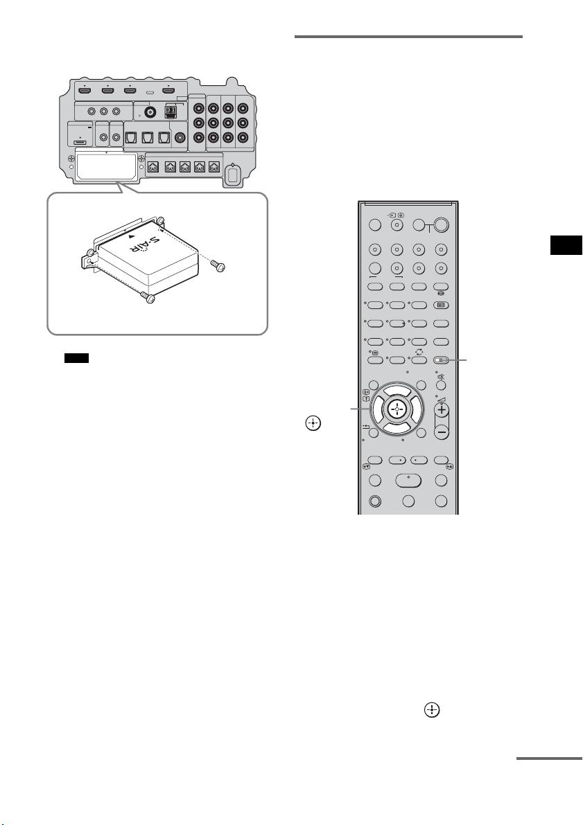
67
GB
Advanced Settings
3 Make sure to use the same screws to
secure the wireless transmitter.
• Do not use other screws to fasten the wireless
transmitter.
To insert the wireless transceiver
into the S-AIR product
For details on installing the wireless transceiver
into the S-AIR product, refer to the operating
instructions of the S-AIR product.
Establishing sound
transmission between the
subwoofer and the S-AIR
product
To establish sound transmission, set the S-AIR
products that you use.
After inserting the wireless transmitter/
transceiver, connect the AC power cord (mains
lead).
To set the ID of the subwoofer
Simply by matching the ID of the subwoofer and
the S-AIR product, you can establish sound
transmission. You can use multiple S-AIR
products by setting a different ID for each
component.
1 Turn on the subwoofer.
The subwoofer turns on.
2 Press AMP MENU.
3 Press x/X repeatedly until “S-AIR SET”
appears, then press or c.
Note
IR REMOTE
VIDEO
DMPORT
DIGITAL COMPONENT VIDEO
SPEAKER ONLY FOR SS-IS15
ECM-AC2 IR-R100
ANTENNA
HDMI
IR IN IR OUT1 IR OUT2
FM AM
75
COAXIAL
DC 5V
0.7A MAX
FRONT R FRONT L SUR R SUR LCENTER
BD IN DVD IN SAT IN
TV IN DVD IN SAT IN SAT IN
ASSIGNABLE
COAXIAL
AUDI O IN
ASSIGNABLE
VIDEO IN
DVD IN SAT IN
MONITOR
OUT
L
Y
P
B
/
C
B
P
R
/
C
R
R
OPTICAL
TV OUT
EZW-T100
E
Z
W
-
T
1
0
0
123
46
78
0
ENTERCLEAR
9
THEATRE
TV
?/1
AV
?/1
TV BD DVD SAT
TOP MENU MENU
BD/DVD
RETURN/EXIT
TV
F1 F2
AMP MENU
DISPLAY
TONE
TUNING - TUNING +
NIGHT
MODE
A/BDIGITALANALOG
DMPORTTUNER/BANDVIDEO
SOUND FIELD
?/1
TV CH -
PRESET -
TV CH +
PRESET +
F
Gg
f
.
HmM
Xx
<
<
>
5
SYSTEM STANDBY
MENU/HOME
TOOLS/
OPTIONS
AMP
MENU
C, X, x, c,
continued
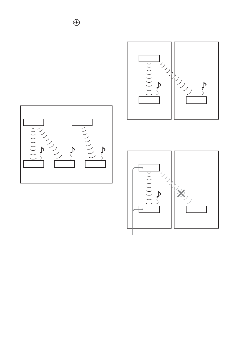
68
GB
4 Press x/X repeatedly until “S-AIR ID”
appears, then press or c.
5 Press x/X repeatedly to select the
desired ID (A, B, or C).
6 Press AMP MENU.
The AMP menu turns off.
To set the ID of the S-AIR product
For details on setting the ID of the S-AIR
product, refer to the operating instructions of the
S-AIR product.
The image of established sound
transmission
To perform the pairing operation
It is easy to set the same ID for the subwoofer
and the S-AIR product to establish sound
transmission. However, neighbors may also
receive your system’s sound if IDs are the same,
or you may receive sound from neighbors. To
prevent this, you can identify the subwoofer with
a specific S-AIR product by performing the
pairing operation.
x When you perform pairing
Before pairing, sound transmission is established
by the ID (example).
Sound transmission is established between the
paired subwoofer and the S-AIR product(s).
1 Place the S-AIR product that you want
to pair near the subwoofer.
2 Match the IDs of the subwoofer and the
S-AIR product. To set the ID of the
system, see “To set the ID of the
subwoofer” (page 67).
To set the ID of the S-AIR product, refer to
the operating instructions of the S-AIR
product.
3 Press AMP MENU.
S-AIR main unit A
(this subwoofer)
S-AIR
product A
S-AIR main unit B
S-AIR
product B
S-AIR
product C
ID A ID A ID B
ID A ID B
Your room Neighbor
ID A ID A
ID A
S-AIR
product A
S-AIR
product B
S-AIR main unit A
(this subwoofer)
Your room Neighbor
ID A ID A
ID A
S-AIR
product A
S-AIR
product B
Pairing
S-AIR main unit A
(this subwoofer)

69
GB
Advanced Settings
4 Press x/X repeatedly until “S-AIR SET”
appears, then press or c.
5 Press x/X repeatedly until “PAIRING”
appears, then press or c.
6 Press x/X repeatedly to select the
desired setting, then press or c.
• START: the subwoofer starts
pairing.
• CONDITION: you can check the current
ID. When the pairing
setting is not made, “NO
PAIRING” appears in the
top panel display.
7 Start pairing of the S-AIR product.
To start paring of the S-AIR product, refer
to the operating instructions of the S-AIR
product.
When sound transmission is established,
“COMPLETE” appears in the top panel
display.
8 Press AMP MENU.
The AMP menu turns off.
• Perform the pairing of the S-AIR product within
several minutes after step 6. If you do not, pairing is
canceled automatically and the “INCOMPLETE”
appears in the top panel display.
To cancel pairing
Perform the ID setting of the subwoofer
according to the procedure of “To set the ID of
the subwoofer” (page 67). If you select a new ID
(you can select the same ID as before), pairing is
canceled.
Enjoying the system’s sound
by using the S-AIR product
You can enjoy the system’s sound by using the
S-AIR product that is compatible with the S-AIR
mode. The S-AIR product can be installed
anywhere, regardless of the location of the
subwoofer, for enjoying the system’s sound in
another room.
For details of the S-AIR product, refer to the
operating instructions of the S-AIR product.
• Sources with copyright protection may not be
playable on S-AIR products.
1 Set the ID of the S-AIR product to that of
the subwoofer.
To set the ID of the subwoofer, see “To set
the ID of the subwoofer” (page 67).
• When you are using another S-AIR product, do not
change the ID of the subwoofer. Set the ID of the
S-AIR product to the same ID as the subwoofer.
• When you pair the subwoofer and another S-AIR
product by the pairing operation, you need to perform
pairing between the subwoofer and the S-AIR
product. For details, see “To perform the pairing
operation” (page 68).
Note
Note
Notes
continued

70
GB
2 Press AMP MENU.
3 Press x/X repeatedly until “S-AIR SET”
appears, then press or c.
4 Press x/X repeatedly until “S-AIR
MODE” appears, then press or c.
5 Press x/X repeatedly to select the
desired function.
• PARTY: the S-AIR product outputs
sound according to function
set on the subwoofer.
• SEPARATE: you can set the desired
function for the S-AIR
product while functions of
the subwoofer do not
change.
When “SEPARATE” is set,
the functions you can select
are “MAIN UNIT,”
“TUNER FM,” “TUNER
AM” and “DMPORT.”
To enjoy the same function
as the subwoofer, select
“MAIN UNIT.”
• When “TUNER FM” or “TUNER AM” is
selected on the subwoofer, you can only select
the same band for the tuner on the S-AIR
product.
6 Press AMP MENU.
The AMP menu turns off.
7 Select the desired function on the
S-AIR product.
When the sound is other than 2 channel
stereo, multi channel sound is down mixed
to 2 channel.
8 Adjust the volume on the S-AIR
product.
123
46
78
0
ENTERCLEAR
9
THEATRE
TV
?/1
AV
?/1
TV BD DVD SAT
TOP MENU MENU
BD/DVD
RETURN/EXIT
TV
F1 F2
AMP MENU
DISPLAY
TONE
TUNING - TUNING +
NIGHT
MODE
A/BDIGITALANALOG
DMPORTTUNER/BANDVIDEO
SOUND FIELD
?/1
TV CH -
PRESET -
TV CH +
PRESET +
F
Gg
f
.
HmM
Xx
<
<
>
5
SYSTEM STANDBY
MENU/HOME
TOOLS/
OPTIONS
AMP
MENU
C, X, x, c,
Note
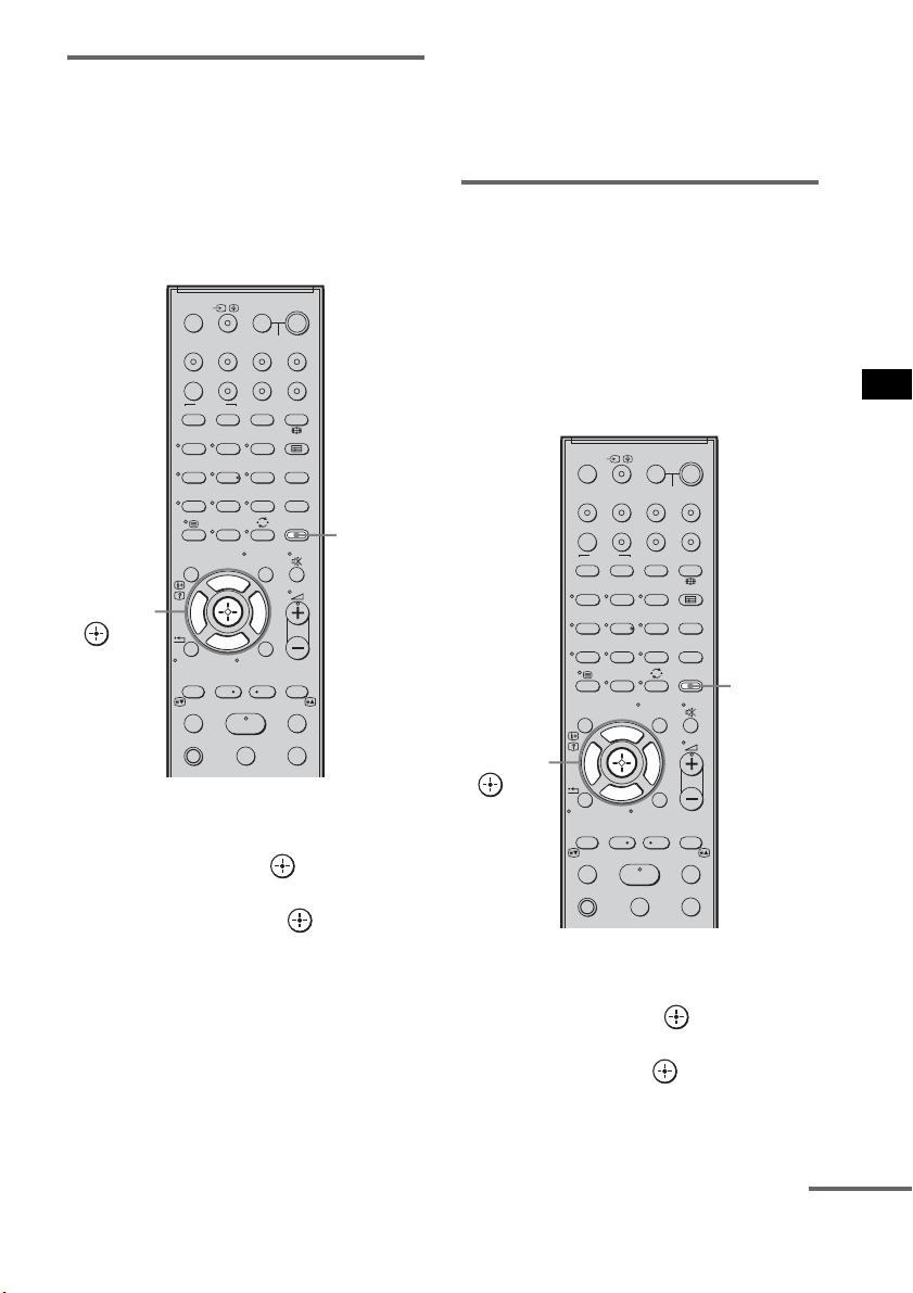
71
GB
Advanced Settings
Changing the channel for
improved sound transmission
If sound transmission is unstable, you can
improve it by changing the “RF CHANGE”
setting. The optimal setting differs depending on
the usage environment.
In most cases, you will not need to change this
setting.
1 Press AMP MENU.
2 Press x/X repeatedly until “S-AIR SET”
appears, then press or c.
3 Press x/X repeatedly to select “RF
CHANGE,” then press or c.
4 Press x/X repeatedly to select the
desired setting.
• AUTO: normally select this. The
subwoofer changes “RF
CHANGE” to “ON” or “OFF”
automatically.
• ON: the subwoofer transmits sound by
searching for a better channel to
transmit.
• OFF: the subwoofer transmits sound by
fixing the channel to transmit.
5 Press AMP MENU.
The AMP menu turns off.
To enjoy the S-AIR product
while the subwoofer is in
standby mode
You can enjoy the S-AIR product while the
subwoofer is in standby mode by setting “S-AIR
STBY” to “STBY ON.”
When you use the timer function of the S-AIR
product, set to “STBY ON” in the “S-AIR
STBY” setting.
1 Press AMP MENU.
2 Press x/X repeatedly until “S-AIR SET”
appears, then press or c.
3 Press x/X repeatedly to select “S-AIR
STBY,” then press or c.
4 Press x/X repeatedly to select the
desired setting.
123
46
78
0
ENTERCLEAR
9
THEATRE
TV
?/1
AV
?/1
TV BD DVD SAT
TOP MENU MENU
BD/DVD
RETURN/EXIT
TV
F1 F2
AMP MENU
DISPLAY
TONE
TUNING - TUNING +
NIGHT
MODE
A/BDIGITALANALOG
DMPORTTUNER/BANDVIDEO
SOUND FIELD
?/1
TV CH -
PRESET -
TV CH +
PRESET +
F
Gg
f
.
HmM
Xx
<
<
>
5
SYSTEM STANDBY
MENU/HOME
TOOLS/
OPTIONS
AMP
MENU
C, X, x, c,
continued
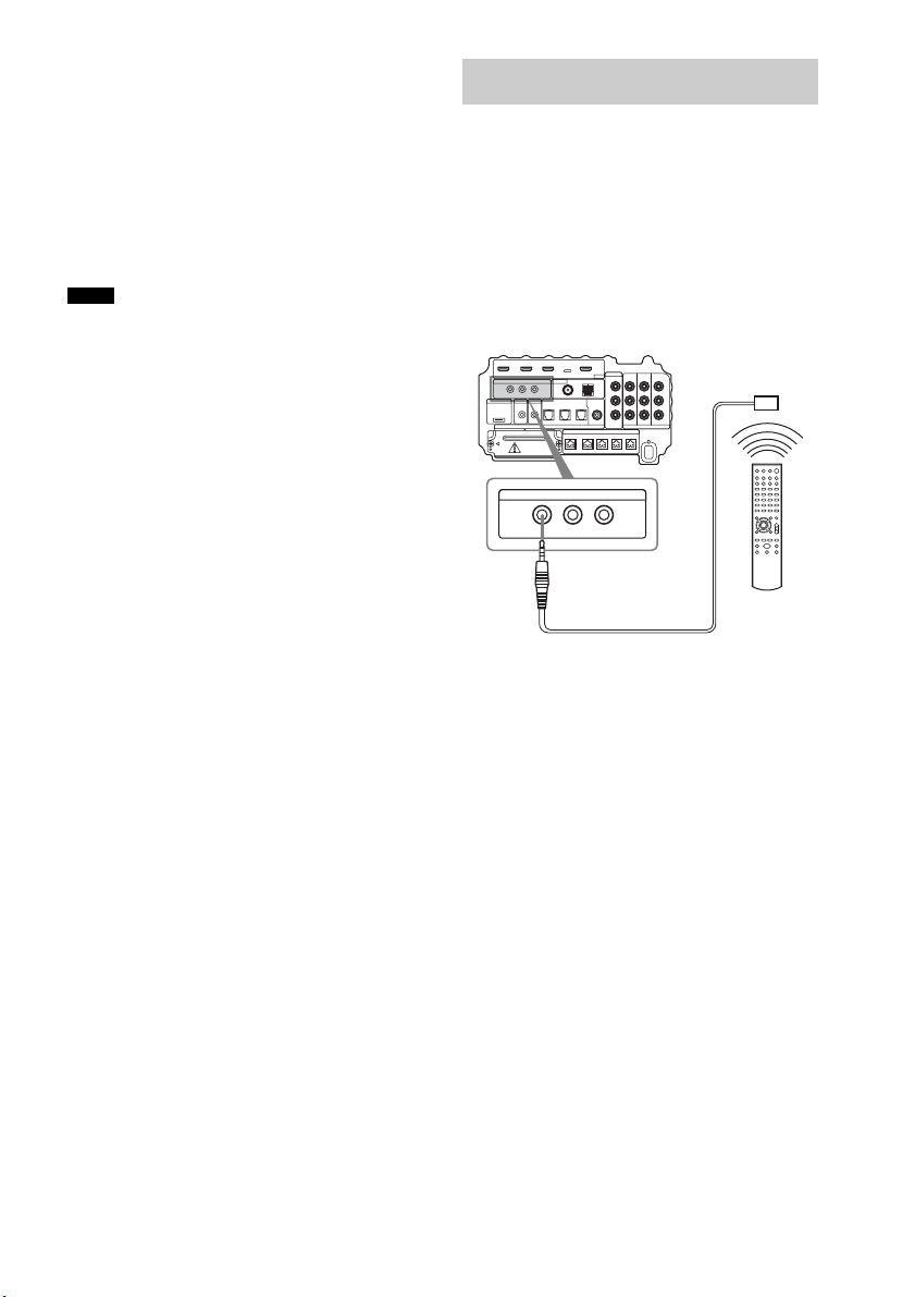
72
GB
• STBY OFF: you cannot enjoy the S-AIR
product while the subwoofer
is in standby mode.
• STBY ON: you can enjoy the S-AIR
product while the subwoofer
is in standby mode or turned
on.
5 Press AMP MENU.
The AMP menu turns off.
• When you set “S-AIR STBY” to “STBY ON,” power
consumption during standby mode increases.
• The sound of the S-AIR product may be cut off when
the subwoofer is operated.
About the IR REMOTE jacks
You can operate the subwoofer without pointing
the remote toward the remote commander
receiver if you connect an IR repeater (not
supplied) to the IR REMOTE jack.
Use an IR repeater when you install the remote
commander receiver in a place where signals
from the remote cannot reach.
Notes
Using the IR repeater
IR REMOTE
IR IN IR OUT1 IR OUT2
Bottom of the subwoofer
IR repeater
(not supplied)
Remote

73
GB
Additional Information
If you experience any of the following
difficulties while using the system, use this
troubleshooting guide to help remedy the
problem before requesting repairs. Should any
problem persist, consult your nearest Sony
dealer. When bringing the system in for repairs,
be sure to bring in the entire system.
General
The power is not turned on.
• Check that the AC power cord (mains lead)
is connected securely.
If “PROTECTOR” and “PUSH POWER”
appears alternately in the top panel display.
Press ?/1 to turn off the system, and check
the following item after “STANDBY”
disappears.
• Is anything blocking the ventilation holes of
the system?
After checking the above item and fixing
any problems, turn on the system. If the
cause of the problem cannot be found even
after checking the above item, consult your
nearest Sony dealer.
Dolby Digital or DTS multi channel sound is
not reproduced.
• Check that the playing Blu-ray Disc, DVD,
etc., is recorded in Dolby Digital or DTS
format.
• Check that audio setting (settings for the
audio output) of the connected component.
The surround effect cannot be obtained.
• Depending on the digital signal, the
surround processing may not work
(page 38).
No sound or only a very low-level sound is
heard from the speakers.
•Press 2 + and check the volume level.
•Press or 2 + to cancel the muting
function.
• Press SOUND FIELD and check the
selected sound field.
• Depending on the source, the sound effect of
the speakers may be less noticeable.
The sound comes from the center speaker
only.
• Check the speaker connections and settings
(page 15, 55).
• Depending on the disc, the sound may come
from the center speaker only.
No sound is heard from the center speaker.
• Check the speaker connections and settings
(page 15, 55).
• Set the sound field to other than “OMNI-
DIRECTIONAL SOUND” (page 38).
• Depending on the source, the effect of the
center speaker may be less noticeable.
No sound or only a very low-level sound is
heard from the surround speakers.
• Check the speaker connections and settings
(page 15, 55).
• Check the selected sound field (page 38).
• Depending on the source, the effect of the
surround speakers may be less noticeable.
• A monaural or stereo (not multi channel)
signal is being played.
The sound is delayed compared to the image
of the TV.
• Set “A/V SYNC” to “SYNC OFF” when
“A/V SYNC” is set.
Connected components
There is no sound or only a very low-level
sound no matter which component is selected.
• Check that this system and components are
connected correctly and securely.
• Check that both this system and the selected
component are turned on.
There is no sound from the selected
component.
• Check that the component is connected
correctly to the audio input jacks for that
component.
Additional Information
Troubleshooting
continuedcontinued

74
GB
• Check that the cords are fully inserted into
the jacks on both the component and this
system.
• Check that the component is selected
correctly.
• If you resume playing a disc when volume is
maximum, there may be no sound. In this
case, turn down the volume, turn off the
system and turn on again.
Sound is interrupted or there is noise.
• Check the output audio formats supported
by this system (page 76).
There is no picture or an unclear picture
appears on the TV screen.
• Select the appropriate input using the input
buttons.
• Set your TV to the appropriate input mode.
• Move your audio components away from the
TV.
• Depending on the DIGITAL MEDIA PORT
adapter, video output may not be possible.
The source image input to the HDMI jack on the
subwoofer is not output from the TV.
• Check the HDMI connection.
• Depending on the playback component, you
may need to set up the component. Refer to
the operating instructions of each
component.
There is picture on the TV screen without
sound.
• Check that the audio assignable setting is
correct (page 63, 64).
Control for HDMI
The Control for HDMI function does not work.
• Check the HDMI connection (page 16).
• Make sure “CTRL: HDMI” is set to “CTRL
ON” in AMP menu.
• Make sure the connected component is
compatible with the Control for HDMI
function.
• Check the Control for HDMI settings on the
connected component. For details, refer to
the operating instructions of the component.
• If you change the HDMI connection, or
connect/disconnect the AC power cord
(main lead), or if there is a power failure,
repeat the procedures of “Preparing for the
“BRAVIA” Sync” (page 41).
• The system may not work correctly if you
select a component that is not compatible
with the Control for HDMI function on the
TV side.
No sound is output from the system and the
TV’s speaker.
• Check the volume of the system and the TV.
• Select the input of the system correctly.
The sound is output from both the system and
the TV.
• If the Control for HDMI function is set to
off, or the selected component is not
compatible with the Control for HDMI
function, turn off the sound of the system or
the TV.
The System Power Off function does not work.
• Change the setting of the TV to turn
connected components off automatically
when you turn off the TV. For details, refer
to the operating instructions of the TV.
An image does not appear on the TV.
• Check whether HDMI IN and HDMI OUT
are connected correctly.
S-AIR function
Sound transmission is not established.
• If you use another S-AIR main unit, place it
more than 8 m away from the system.
• Confirm the ID of the subwoofer and the
S-AIR product (page 67).
• You performed pairing the subwoofer and
another S-AIR product. Perform pairing of
the desired S-AIR product (page 68).
• The S-AIR product is paired to another
S-AIR product. Cancel pairing.
• Install the system away from other wireless
products.
• Stop using another wireless product.

75
GB
Additional Information
• The S-AIR product is turned off. Make sure
the AC power cord (mains lead) is connected
and turn on the S-AIR product.
No sound is heard from the S-AIR product.
• If you use another S-AIR main unit, place it
more than 8 m away from the system.
• Confirm the ID of the subwoofer and the
S-AIR product (page 67).
• Confirm the pairing setting (page 68).
• Install the S-AIR main unit and S-AIR sub
unit closer together.
• Avoid use of equipment that generates
electromagnetic energy, such as a
microwave oven.
• Install the S-AIR main unit and S-AIR sub
unit away from other wireless products.
• Stop using another wireless product.
• Change the “RF CHANGE” setting
(page 71).
• Change the ID settings of the S-AIR main
unit and S-AIR sub unit.
• Turn off the system and S-AIR product, then
turn them on.
There is noise or the sound skips.
• If you use another S-AIR main unit, place it
more than 8 m away from the system.
• Install the S-AIR main unit and S-AIR sub
unit closer together.
• Avoid use of equipment that generates
electromagnetic energy, such as a
microwave oven.
• Install the S-AIR main unit and S-AIR sub
unit away from other wireless products.
• Stop using another wireless product.
• Change the “RF CHANGE” setting
(page 71).
• Change the ID settings of the S-AIR main
unit and S-AIR sub unit.
Other
The remote does not function.
• Check that the subwoofer and the remote
commander receiver are connected correctly
and securely.
• Point the remote at the remote sensor ( ) on
the remote commander receiver.
• Remove any obstacles in the path between
the remote and the remote commander
receiver.
• Replace both batteries in the remote with
new ones, if they are weak.
• Press one of the input buttons (TV, BD,
DVD, SAT, TUNER/BAND, or DMPORT)
on the remote to select the component you
want to operate (page 50).
The volume turns down when the output
method changes from the TV speaker to the
system speaker.
• The Volume Limit function is working. For
details, see “Using the Volume Limit
function” (page 44).
If the system still does not
operate properly after performing
the above measures, reset the
system as follows:
Use buttons on the subwoofer for the operation.
1 Press ?/1 to turn on the power.
2 Press INPUT SELECTOR, VOLUME –,
?/1 at the same time.
“COLD RESET” appears and the system is
reset. AMP menu, sound field, etc., return to
the default settings.

76
GB
Formats supported by this
system
Digital input formats supported by this system
are as follows.
* Linear PCM accepts sampling frequencies of no
more than 96 kHz.
Amplifier section
Power output (rated)
Front L / Front R (rated): 35 W + 35 W
(at 10 ohms, 1 kHz, 1 %
THD)
RMS output power (reference)
Front L / Front R*: 50 W + 50 W
(at 10 ohms, 1 kHz, 10 %
THD)
Center*: 50 W
(at 10 ohms, 1 kHz, 10 %
THD)
Surround L / Surround R*: 50 W + 50 W
(at 10 ohms, 1 kHz, 10 %
THD)
Subwoofer*: 100 W (at 4 ohms, 70 Hz,
10 % THD) + 100 W (at 4
ohms, 500 Hz, 10 % THD)
* Depending on the sound field settings and the source,
there may be no sound output.
Inputs (Analog)
VIDEO Sensitivity: 700 mV
Impedance: 33 kohms
Inputs (Digital)
TV, DVD Optical
SAT Coaxial, optical
HDMI section
Connector HDMI 19pin-standard
connector
Video inputs/outputs BD, DVD, SAT:
640 × 480p@60 Hz
720 × [email protected]/60 Hz
1440 × [email protected]/60 Hz
(pixel sent 2 times)
1280 × [email protected]/60 Hz
1920 × 1080i@59.94/
60 Hz
1920 × [email protected]4/
60 Hz
720 × 576p@50 Hz
1440 × 576p@50 Hz
(pixel sent 2 times)
1280 × 720p@50 Hz
1920 × 1080i@50 Hz
1920 × 1080p@50 Hz
1920 × 1080p@24 Hz
Audio inputs BD, DVD, SAT: Linear
PCM 7.1ch/
Dolby Digital/ DTS
Tuner section
System PLL quartz-locked digital
synthesizer
FM tuner section
Tuning range 87.5 – 108.0 MHz
(50 kHz step)
Antenna (aerial) FM wire antenna (aerial)
Antenna (aerial) terminals 75 ohms, unbalanced
Intermediate frequency 10.7 MHz
AM tuner section
Tuning range
European models: 531 kHz – 1,602 kHz (with
the interval set at 9 kHz)
Australian models: 531 kHz – 1,710 kHz (with
the interval set at 9 kHz)
530 kHz – 1,710 kHz (with
the interval set at 10 kHz)
Antenna (aerial) AM loop antenna (aerial)
Intermediate frequency 450 kHz
Video section
Input VIDEO: 1 Vp-p 75 ohms
Inputs/Outputs COMPONENT:
Y: 1 Vp-p 75 ohms
PB/CB, PR/CR: 0.7 Vp-p
75 ohms
Specifications
Format Supported/Not supported
Dolby Digital a
DTS a
Linear PCM (2ch)* a
Linear PCM (5.1ch,
7.1ch)* (Only on
HDMI)
a
Dolby Digital Plus ×
Dolby True HD ×
DTS-HD ×

77
GB
Additional Information
Speakers
Front/Center/Surround (SS-IS15)
Speaker system Full range speaker system
Speaker unit 35 mm
Rated impedance 10 ohms
Dimensions (approx.) 45 × 55 × 40 mm
(w/h/d)
Mass (approx.) 0.07 kg
Speaker cords 4.5 m × 2, 3 m × 1, 12 m × 2
Subwoofer (SA-WIS100)
Speaker system 2 Way 2 Drivers
Subwoofer speaker system
Speaker unit 120 mm + 160 mm
Rated impedance 4 ohms
Dimensions (approx.) 238 × 441 × 434 mm
(w/h/d)
Mass (approx.) 14.5 kg
Power requirements 220 – 240 V AC, 50/60 Hz
Power consumption
On: 115 W
Standby mode: 0.3W (when “CTRL: HDMI”
and “S-AIR STBY” are set to “OFF.”)
Power output
(DIGITAL MEDIA PORT)DC OUT: 5 V, 700 mA
Remote commander receiver (IR-R100)
Dimensions (approx.) 46 × 19 × 45 mm
(w/h/d)
Mass (approx.) 0.15 kg
Design and specifications are subject to change without
notice.
Dolby Digital
This movie theatre sound format is more
advanced than Dolby Surround Pro Logic. In this
format, the surround speakers output stereo
sound with an expanded frequency range, and a
subwoofer channel for deep bass is
independently provided. This format is also
called “5.1” with the subwoofer channel
designed as the 0.1 channel (since it functions
only when a deep bass effect is needed). All six
channels in this format are recorded separately
for superior channel separation. Furthermore,
since all the signals are processed digitally, less
signal degradation occurs.
Dolby Pro Logic II
Dolby Pro Logic II creates five full-bandwidth
output channels from 2 channel sources. This is
done using an advanced, high-purity matrix
surround decoder that extracts the spatial
properties of the original recording without
adding any new sounds or tonal colorations.
DTS
Digital audio compression technology
developed by Digital Theater Systems, Inc. This
technology conforms to 5.1-channel surround.
This format comprises of stereo rear channel and
there is discrete subwoofer channel in this
format. DTS provides the same 5.1 discrete
channels of high quality digital audio. The good
channel separation is realized due to the all
channel data being recorded discretely and
processed in digitally.
HDMI
HDMI (High-Definition Multimedia Interface)
is an interface that supports both video and audio
on a single digital connection, allowing you to
enjoy high quality digital picture and sound. The
HDMI specification supports HDCP (High-
bandwidth Digital Contents Protection), a copy
protection technology that incorporates coding
technology for digital video signals.
• Standby power consumption 0.3 W.
• Halogenated flame retardants are not
used in the certain printed wiring
boards.
• Over 85 % power efficiency of
amplifier block is achieved with the
full digital amplifier, S-master.
Glossary
continuedcontinued

78
GB
PCM (Pulse Code Modulation)
A method of converting analog audio to digital
audio for easy enjoyment of digital sound.
S-AIR (Sony Audio Interactive Radio
frequency)
Recent times have seen the rapid spread of DVD
media, Digital Broadcasting, and other high-
quality media.
To ensure that the subtle nuances of these high-
quality media are transmitted with no
deterioration, Sony has developed a technology
called “S-AIR” for the radio transmission of
digital audio signals with no compression, and
has incorporated this technology into the
EZWRT10/EZW-T100.
This technology transfers digital audio signals
with no compression using the 2.4 GHz band
range of ISM band (Industrial, Scientific, and
Medical band), such as wireless LANs and
Bluetooth applications.
S-master
S-master is an all-digital amplifier technology
developed by Sony, which effectively minimizes
the occurrence of sound fragmentation and jitter,
delivering superb dialog clarity and faithful
reproduction of the original sound. The compact
amplifier section supports a higher power
efficiency and improved thermal performance.
x.v.Colour
x.v.Colour is a more familiar term for the
xvYCC standard proposed by Sony, and is a
trademark of Sony. xvYCC is an international
standard for color space in video.
This standard can express a wider color range
than the currently used broadcast standard.

79
GB
Additional Information
A
A. ASSIGN 63
A. CAL CLEAR
28
A. CAL MENU
26, 28
A. CAL START
26
A/V SYNC
59
AMP menu
54
AUDIO
63, 64
AUDIO DRC
60
Auto Calibration
24
B
Blu-ray Disc player (recorder)
connecting
16
“BRAVIA” Sync
41
C
CENTER SP 55
CNT DIST
56
CNT LEVEL
57
CTRL: HDMI
42
CUSTOMIZE
58, 59, 60, 61, 62
D
D. ASSIGN 64
DIGITAL MEDIA PORT
connecting 30
DIMMER
61
DISPLAY
48, 61
DUAL MONO
58
DVD player (recorder)
connecting
16, 19
F
FL DIST 56
FL LEVEL
57
FM Mode
47
FR DIST
56
FR LEVEL
57
H
HDMI
connecting
16
I
Installing 7
L
LEVEL 57
M
MUTING 34
N
Naming preset stations 48
NIGHT MODE
40
P
PAIRING 68
“PlayStation 3”
connecting 16
Presetting radio stations
46
R
Radio 47
Radio Stations
46
RDS
49
Reassigning the analog audio input
63
Reassigning the digital audio input
64
Remote
assignments 53
before use
6
operating
34, 50
RF CHANGE
71
Index
continuedcontinued

80
GB
S
S-AIR 65
S-AIR ID
67
S-AIR MODE
69
S-AIR SET
67, 69, 71
S-AIR STBY
71
Satellite tuner
connecting 16, 20
SET HDMI
42, 44
SL DIST
56
SL LEVEL
57
Sleep timer
62
Sound field
38
SP SETUP
55, 56
Speakers level
57
Speakers setting
55, 56
SR DIST
56
SR LEVEL
57
SUR SP
55
SW DIST
56
SW LEVEL
57
T
TEST TONE 57
TONE
40
V
VCR
connecting
21
VOL LIMIT
44


Sony Corporation Printed in Malaysia
(2)