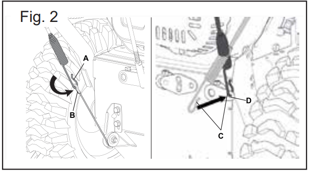
1. Attach the left cable (A, Fig.2) on the upper handle to cable (B, Fig.2) out from the transmission box, while the right cable (C, Fig.2) to the support (D, Fig.2).
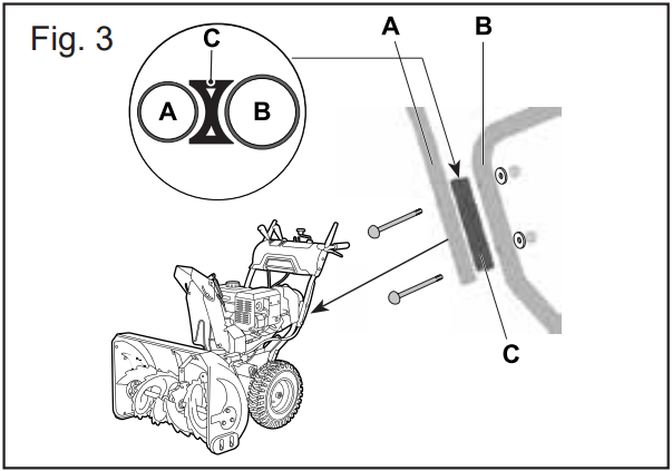
2. Attach the upper handle to the lower handle with fixing bolt, nut & washer supplied, with fixing bracket (C, Fig.3) in between two handles(A, B, Fig3), then tighten by wrench supplied.
STEP TWO: Assemble the drive control rod
1. Insert the angle side (A, Fig.4) of drive control rod into the hole on the lever (B, Fig.4 ) to connect it to the transmission, and secure it in place with the nut.
2. Attach the nose end of the control rod (D, Fig.4 ) to the pin on the bottom part of the gear lever (E, Fig.4), and secure it in place with the B pin.
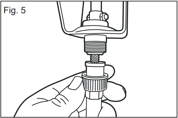
STEP THREE: Assemble the soft shaft
Plug the soft shaft on the side of rotater from the dashboard, then rotate it tight to fix it
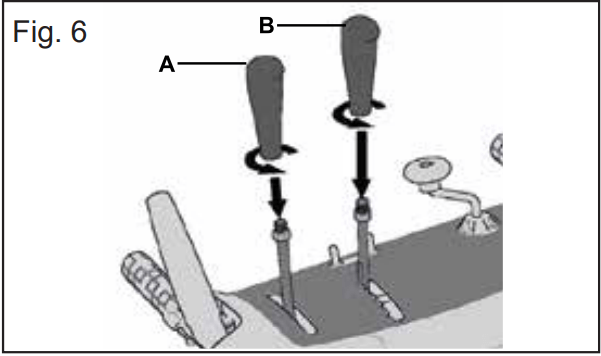
STEP FOUR: Assemble the control handle knobs
Screw the control handle knobs to the handles on the panel. Make the control handle knobs are in the proper direction, then screw the nuts to fix the knobs. (Fig. 6)
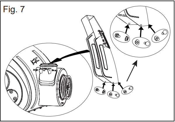
STEP FIVE: Assemble the chute
1. Place the chute on the chute seat, fix it with carriage bolts inside and nuts outside. (Fig. 7).
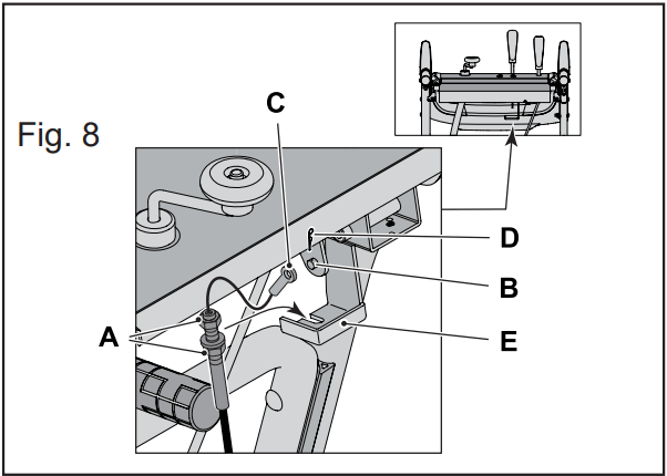
2. Before insert chute cap control cable end (C,Fig. 8) in position, release the two screws A (Fig. 8). Secure it to the bar (B,Fig.8) with a B pin (D,Fig.8),then tighten the two screws to the base (E,Fig.8) to secure the cable. Press the cable onto the guider (A,Fig.9) for affixing
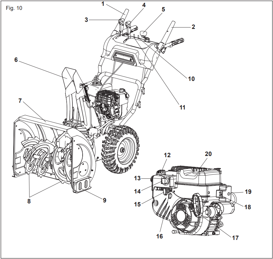
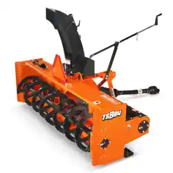
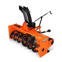
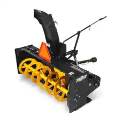
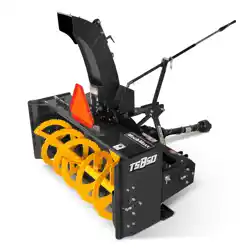
KNOW YOUR 24" GAS SNOWBLOWER
Auger Control
Drive Control
Shift Lever / Speed Control
Chute deflector control lever
Chute direction control joystick
Chute Assembly
Auger housing with clean-out tool
Auger
Skid Shoes (plastic + steel)
LED headlight switch
Heating handle switch
Choke control lever
Primer
Ignition key
Throttle control lever
Fuel valve lever
Recoil starter handle
Electric outlet
Electric starter button
Fuel tank cap
OPERATION
BEFORE OPERATION
Check The General Condition
Look around and underneath the engine for signs of oil or gasoline leaks.
Remove any excessive dirt or debris, especially around the muffler and recoil starter.
Look for signs of damage.
Check that all shields and covers are in place, and all nuts, bolts, and screws are tightened.
Check The Engine
There is no fuel or oil in the engine. Fill with fuel and add 5W-30 prior to first use.
Check the fuel level.
Check the oil level.
OPERATION
Starting The Engine
Attach spark plug wire to spark plug. Make certain the metal loop on the end of the spark plug wire (inside the rubber boot) is fastened securely over the metal tip on the spark plug.
Make certain both the auger control and drive control are in the disengaged (released) position.
Move throttle control to FAST (rabbit) position. Insert ignition key into slot. Make sure it snaps into place. Do not attempt to turn the key.
Make sure fuel valve lever is in the ON position.
NOTE: The engine cannot start without the key is fully inserted into the ignition switch.
Electric Starter
Determine that your home’s wiring is a two-wire grounded system. Ask a licensed electrician if you are not certain.
WARNING: The optional electric starter is equipped with a grounded two-wire power plug, and is designed to operate on 120 volt AC household current. It must be used with a properly grounded two-prong receptacle at all times to avoid the possibility of electric shock. If your home’s wiring system is not a grounded system, do not use this electric starter under any conditions.
If your home electrical system is grounded, but a two-hole extension cord is not available, do not use your snow blower’s electric starter. Follow all instructions carefully prior to operating the electric starter.
If you have all of the above, proceed as follows:
1. Plug the extension cord into the outlet located on the engine’s surface. Plug the other end of extension cord into a 120-volt, grounded, AC outlet in a well-ventilated area.
2. Place choke control to FULL choke position (for a cold engine start).
NOTE: If the engine is already warm, place choke control in the OFF position instead of FULL.
3. Push the primer two or three times for cold engine start, , marking sure to cover vent hole in the center of the primer when pushing. DO NOT use primer to restart a warm engine after a short shutdown.
4. Push start button to start engine.
5. Once the engine starts, release starter button.
6. AS the engine warms, slowly rotate the choke control to the OFF position. if the engine falters, quickly rotate the choke control back to FULL and then slowly into the OFF position again.
7. When disconnecting the extension cord, always unplug the end at the wall outlet then unplug the opposite end from the snowblower.
Recoil Starter
1. Rotate choke control to FULL choke position (cold engine start).
NOTE: If the engine is already warm, place choke control in the OFF position instead of FULL.
2. Push the primer two or three times for cold engine start, making sure to cover vent hole in the center of the primer when pushing.
NOTE: DO NOT use primer to restart a warm engine after a short shutdown.
NOTE: Additional priming maybe necessary if the temperature is below -10°.
3. Grasp the recoil starter handle and slowly pull the rope out. At the point where it becomes slightly harder to pull the rope, slowly allow the rope to recoil.
4. Pull the starter handle with a firm, rapid stroke. Do not release the handle and allow it to snap back. Keep a firm hold on the starter handle and allow it to slowly recoil.
5. As the engine warms, slowly rotate the choke control to the OFF position. If the engine falters, quickly rotate the choke control back to the FULL position and then slowly into the OFF position again.
NOTE: Allow the engine to warm up for a few minutes after starting. The engine will not develop full power until reaching operating temperatures.
Stopping The Engine
Run engine for a few minutes before stopping to help dry off any moisture on the engine.
To help prevent possible starter freeze-up, proceed as follows:
Electric Strarter
Connect extension cord to the electric starter outlet on the engine, then to120 volt AC outlet.
With the engine running, push the starter button and allow the starter for spin for several seconds. The noise made in the starter is normal. The engine’s starter is not being harmed.
When disconnecting the extension cord, always unplug the end at the wall outlet before unplugging the opposite end from the snowblower.
Move throttle control to STOP (tortoise) position.
Remove the ignition key and store in a safe place.
Wipe all snow and moisture from the area around the engine as well as the area in and around the drive control and auger control. Also, engage and release both controls several times.
Recoil Starter
With engine running, pull the starter rope with a rapid, continuous full arm stroke three or four times. Pulling the starter rope will produce a loud clattering sound, which is not harmful to engine.
Move throttle control to STOP (tortoise) position.
Remove the ignition key and store in a safe place.
Wipe all snow and moisture form the area around the engine as well as the area in and around the drive control several times
OPERATING YOUR SNOWBLOWER
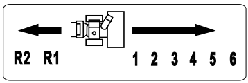
The shift lever is located between the upper handles. Place the shift lever into any of 8 positions to control the direction of travel and ground speed.
Forward
There are six forward (F) speeds. Position one (1) is the slowest and position six (6) is the fastest.
Reverse
There are two reverse (R) speeds. One (R1) is the slower and the other (R2) is the faster.
Primer
Depressing the primer forces fuel directly into the engine’s carburetor to aid in cold-weather starting.
Choke Control
The choke control is found on the rear of the engine and is activated by rotating the knob clockwise to FULL position and counterclockwise to OFF position. Activating the choke control closes the choke plate on the carburetor and aids in starting the engine
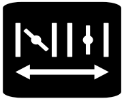
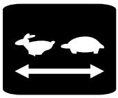
Throttle Control
The throttle control is located on the engine. It regulates the speed of the engine and will shut off the engine when pushed down to the end (tortoise) completely.
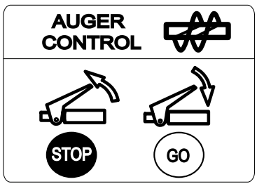
Auger Control
The auger control is located on the right handle. Squeeze the control grip against the handle to engage the augers and start snow throwing action. Release to stop.
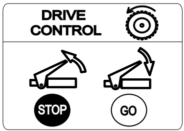
Drive Control
The drive control is located on the left handle. Squeeze the control grip against the handle to engage the wheel drive. Release to stop.
This snow blower has EXCLUSIVE Simultaneous Engagement System for one-hand operation and Built-in auto-turn power steering system, this technology enables effortless power steering on your snowblower. This system is able to sense the direction your trying to turn the snowblower and engages the drive system to assist turning in the desired direction.
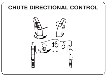
Chute Directional Control
The chute directional control is located on the panel of the snowblower.
To change the direction in which snow is thrown, turn chute directional control as follows:
Crank control joystick clockwise to discharge to the right.
Crank control joystick counterclockwise to discharge to the left.
Chute Deflector (Up/Down control lever)
Manually operate the control lever forward and backward. The more backward the position, the higher the height of snow is thrown.
LED Headlight Switch
Located on control panel. Turn ON to illuminate the headlight LED and OFF to douse.
Heating Handle Switch
located on control panel. Turn ON to heat both operation handles and OFF to stop.
Slid Shoes
Position the skid shoes based on surface conditions. Adjust upward for hard-packed snow. Adjust downward when operating on gravel or crushed rock surfaces.This machine is equipped with plastic and steel skid shoes for different surface.
Recoil Starter Handle
This handle is used to manually start the engine.
Requires the use of a two-prong outdoor extension cord and a 120V power source.
NOTE: This machine is not equipped with an extension cord.
Augers
When engaged, the augers rotate and draw snow into the auger housing.
Chute Assembly
Snow drawn into the auger housing is discharged out through the chute assembly.
Chute Clean-Out Tool
The chute clean-out tool is conveniently fastened to the rear of the auger housing with a mounting clip. Should snow and ice become clogged in the chute assembly during operation, proceed as follows to safely clean the chute assembly and chute opening.
1. Release both the Auger Control and the Drive Control.
2. Stop the engine by removing the ignition key.
3. Remove the clean-out tool from the clip which secures it to the rear of the auger housing.
WARNING: The muffler, engine and surrounding areas become hot and can cause a burn. DO not touch.
4. Use the shovel-shaped end of the clean-out tool to dislodge and scoop any snow and ice which has formed in and near the chute assembly.
5. Refasten the clean-out tool to the mounting clip on the rear of the auger housing, reinsert the ignition key and start the snow thrower’s engine.
6. While standing in the operator’s position (behind the snow thrower), engage the auger control for a few seconds to clear any remaining snow and ice from the chute assembly.
To Engage Drive
1. With the throttle control in the Fast (rabbit) position, move shift lever into one of the six forward (F) positions or two reverse (R) positions. Select a speed appropriate for the snow conditions and a pace you’re comfortable with. When selecting a Drive Speed, use the slower speed until you are comfortable and familiar with the operation of the snowblower.
2. Squeeze the auger control against the handle and the auger will turn. Release it and the augers will stop.
3. Squeeze the drive control against the handle and snow thrower will move. Release it and drive motion will stop.
IMPORTANT: NEVER reposition the shift lever (change speeds or direction of travel) Without first releasing the drive control and bringing the snow thrower to a complete stop. Doing so will result in premature wear to the snow blower drive system.
MAINTENANCE
Gas Cap
Unthread the gas cap to add gasoline to the fuel tank.
Gasoline
WARNING: Use extreme care when handling gasoline is extremely flammable and the vapors are explosive. Never fuel the machine indoors or while the engine is hot or running. Extinguish cigarettes, cigars, pipes and other sources of ignition.
Store gasoline in a clean, approved container and keep the cap in place on the container.
Make sure that the container from which you pour the gasoline is clean and free from rust or other foreign particles.
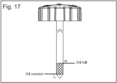
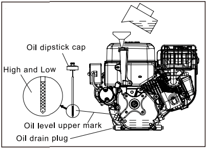
Oil Fill
Engine oil level can be checked and oil added through the oil fill.
Before Starting Engine
Do not start the engine until filled with oil. The engine can be seriously damaged without oil.
1. Place the machine on a level floor.
2. Loosen the dipstick and read the oil level.
3. The oil level shall be between the marks “HIGH” and “LOW”.
4. It necessary fill with oil up to the HIGH mark
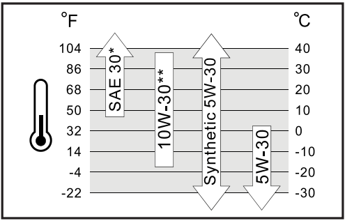
5. Use good quality oil marked A.P.I. service SF, SG or SH.
Use SAE 5W30 oil. Use SAE 0W30 oil for temperatures under -18ºC
Do not use SAE 10W40.
Lubrication
WARNING: Before lubricating, repairing, or inspecting, disengage all controls and stop engine. Wait until all moving parts have come to a complete stop.
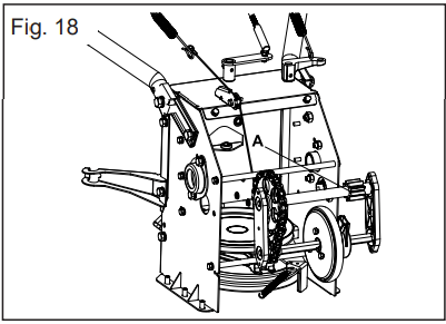
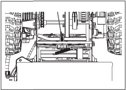
Gear Shaft
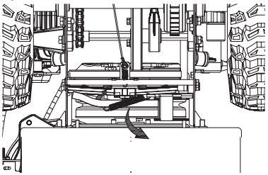
The gear (hex) shaft (FIG.18A) should be lubricated at least once a season or after every 25 hours of operation.
1. Remove the lower frame cover by removing the two screws which secure it.
2. Apply a light coating of an all-weather multipurpose grease to the hex shaft.
IMPORTANT: Avoid oil spillage on rubber friction
Wheels
At least once a season, remove both wheels. Clean and coat the axles with a multipurpose automotive grease before reinstalling wheels.
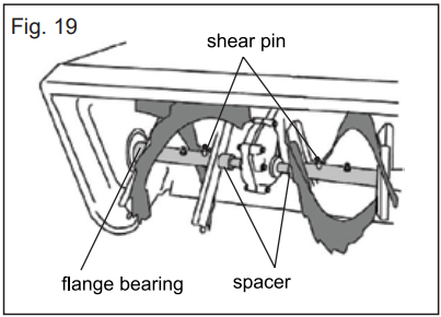
Auger Shaft
At least once a season, remove the shear pins on auger shaft. Spray lubricant inside shaft, around the spacers. Also lubricate the flange bearings found at either end of the shaft.
Gear Case
The auger gear case has been filed with grease and sealed at the factory. If disassembled from any reason, lubricate with 160g of new grease.
NOTE: Do not over fill the gear case. Damage to the seals could result. Be sure the vent plug is free of grease in order to relieve pressure.
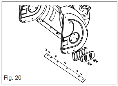
Shave Plate and Skid Shoes
The shave plate and skid shoes on the bottom of the snowblower are subject to wear. They should be checked periodically and replaced when necessary.
To remove skid shoes:
Remove the four carriage bolts and hex flange nuts which secure them to the snowblower.
Reassemble new skid shoes with the four carriage bolts (two on each side) and hex flange nuts.
To remove shave plate:
Remove the carriage bolts and hex nuts which attach it to the snowblower housing.
Reassemble new shave plate, making sure heads of carriage bolts are to the inside of housing and the new shave plate is 2-4 mm above the ground. Tighten securely.
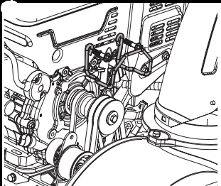
Auger Belt Replacement
To remove and replace your snowblower's auger belt, proceed as follows:
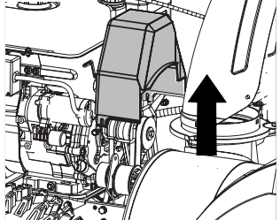
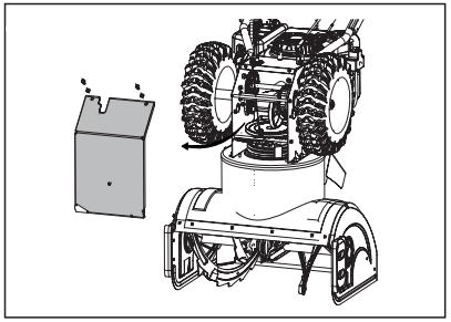
1. Remove the belt cover on the front of the engine by removing the two self-tapping screws.
NOTE: Drain the gasoline from the snowblower, or place of plastic under the gas cap.
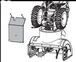
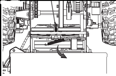
2. Carefully pivot the snow thrower up and forward so that it rests on the auger housing. Remove the frame cover from the underside of the snowblower by removing four self-tapping screws which secure it.
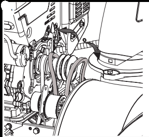
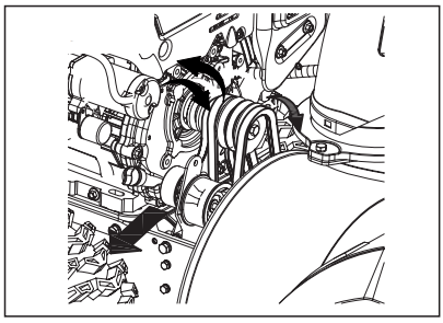
3. Loosen and remove the shoulder screw of the belt keeper.
4A. Roll the auger belt off the engine pulley
4B. Unhook the support bracket spring from the frame.
5. Remove the belt from around the auger pulley, and slip the belt between the support bracket and the auger pulley. Reassemble auger belt by above instructions in reverse order.
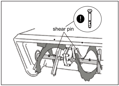
Augers
The auger are secured to the spiral shaft with two shear pins and cotter pins. If the auger should strike a foreign object or ice jam, the snowblower is designed so that the pins may shear.
If the augers will not turn, check to see if the pins have sheared. One set of replacement shear pins has been provided with the snowblower. When replacing pins, spray an oil lubricant into shaft before inserting new pins.
Drive Belt Replacement
To remove and replace your snowblower's auger belt, proceed as follows:
1. Remove the belt cover in the front of the engine by removing the two self-tapping screws.
NOTE: Drain the gasoline from the snow thrower or place a piece of plastic under the gas cap.
2. Carefully pivot the snow thrower up and forward so that it rests on the auger housing. Remove the frame cover from the underside of the snowblower by removing four self tapping screws which secure it.
3A. Loosen and remove the shoulder screw of the belt keeper
3B. Roll the two anger belts off the engine pulley,see section "AUGER BELT REPLACEMENT".
3C. Then lifr the drive belt off engine pulley.
4. Slip the drive belt off the pulley and between friction wheel and friction wheel disc.
5. Replace belt in the reverse order.
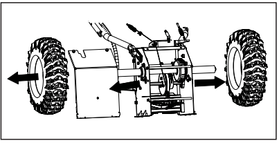
Friction Wheel Removal
If the snowblower fails to drive with the drive control engaged, and performing the drive control cable adjustment fails to correct the problem, the friction wheel may need to be replaced, Follow the instructions below.
1. Examine the friction wheel for signs of wear or cracking and replace if necessary.
Place the shift lever in third Forward (F3) position.
Drain the gasoline from the snowblower, or place a piece of Plastic under the gas cap.
Carefully pivot the snow thrower up and forward so that it rests on the auger housing.
2A. Remove the frame cover from the underside of the snowblower by removing two selftapping screws which secure it .
2B. Remove the left and right wheels by removing the snap joints on side of wheels .
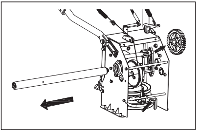
3. Pull out the drive shafts, remove the gear.
4. Pull the hex shaft by force, remove the hex shaft and transition shaft assembly off.
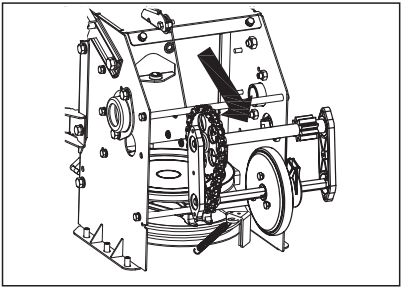
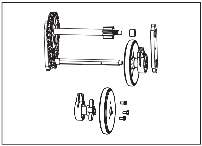
5. Remove the three screws which secure the friction wheel’s side plates together.
6. Slide the friction wheel assembly back onto the hex shaft and follow the steps above in reverse order to reassemble components.
CHECKING ENGINE OIL
1. Be sure engine is upright and level.
2. Unscrew oil fill cap from filter tube and wipe dipstick clean.
3. Screw cap back into oil filter tube. Tighten securely.
4. Unscrew and remove oil fill cap from oil filter tube. Note oil level. If oil reading on dipstick is below “LOW” mark, slowly add oil to reach “HIGH” level,
5. Scew oil fill cap back into oil filter tube, tighten securely.
6. Wipe away any spilled oil.
Changing Engine Oil
To avoid engine damage, it is important to:
Check oil level before each use and every five operating hours.
Change oil after first two operating hours and every 25 operating hours thereafter.
Engine should still be warm but not hot from recent use.
1. Locate the oil drain plug
2. Be sure the gas cap is on and is tighten securely.
3. Clean area around oil drain plug
4. Place approved recyclable oil container under oil drain plug.
5. Remove oil drain plug and drain oil.
Note: Used oil must be disposed of at a proper collection center.
6. Install oil drain plug and tighten securely.
7. Refill the engine with recommended oil, Recommended Oil as Usage chart.
8.Wipe away any spilled oil.
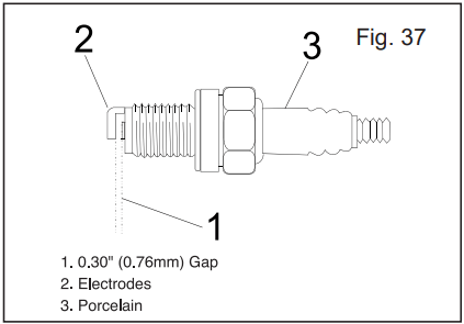
Checking Spark Plug
Check spark plug yearly or every 100 operating hours
1. Clean area around spark plug.
2. Remove and inspect spark plug.
3. Replace spark plug if porcelain is cracked or if electrodes are pitted, burned or fouled with deposits.
4. Check electrode gap with a feeler gauge and set gap to 0.030(0.76mm) if necessary.
5. Reinstall spark plug and tighten securely
NOTE: A resistor spark plug must be used for replacement. Contact the distributor or local agent for a replacement spark plug.
Carburetor
If you suspect your carburetor needs adjusted, contact the distributor or local agent, engine performance should not be affected at altitudes up to 7000 feet (2134 meters). For operation at higher elevations, contact the distributor or local agent.
Engine Speed
WARNING: Avoid serious injury or death, DO NOT modify engine in any way, Tampering with the governor setting can cause the engine and equipment to operate at unsafe speeds. NEVER tamper with factory setting of engine governor. Running the engine faster than the speed set at the factory is dangerous.
TROUBLESHOOTING
PROBLEM
CAUSE
CORRECTION
Does not start
1. Safety ignition key is not inserted.
2. Out of fuel.
3. ON/OFF switch is OFF.
4. Choke in OFF position.
5. Primer not depressed.
6. Engine is flooded.
7. Spark plug wire is disconnected.
8. Bad spark plug.
9. Stale fuel.
10. Water in fuel.
11. Vapor locked fuel line.
1. Insert safety ignition key.
2. Fill fuel tank with fresh, clean gasoline.
3. Move ON/OFF switch to ON position.
4. Move to FULL position.
5. Prime as instructed in the Operation section of this manual.
6. Wait a few minutes before restarting, DO NOT prime.
7. Connect wire to spark plug.
8. Replace spark plug.
9. Empty fuel tank & carburetor, refill with fresh, clean gasoline.
10. Empty fuel tank & carburetor, refill with fresh, clean gasoline.
11. Ensure all the fuel line is below the outlet of the fuel tank. Fuel line should run continuously down from fuel tank to carburetor.
Loss of power
1. Spark plug wire loose.
2. Throwing too much snow.
3. Fuel tank cap is covered with ice or snow.
4. Dirty or clogged muffler.
5. Improper cable length.
6. Blocked muffler.
7. Blocked carburetor air intake.
1. Reconnect spark plug wire.
2. Reduce speed and width of swath.
3. Remove ice and snow on and around fuel tank cap.
4. Clean or replace muffler.
5. Adjust cable.
6. Clear blockage (ensure engine is cool).
7. Clear blockage (ensure engine is cool).
Engine idles or runs roughly
1. Choke is in FULL position.
2. Blockage in fuel line.
3. Stale fuel.
4. Water in fuel.
5. Carburetor is in need of replacing
6. Belt stretch.
1. Move choke to OFF position.
2. Clean fuel line.
3. Empty fuel tank & carburetor, refill with fresh, clean gasoline.
4. Empty fuel tank & carburetor, refill with fresh, clean gasoline.
5. Contact an authorized service center/department.
6. Replace auger v-belt.
Excessive vibration / Handle movement
1. Loose parts or damaged augers or impeller.
2. Handles not positioned correctly.
3. Adjustment lever nuts are loose.
1. Tighten all fasteners. Replace damaged parts. If vibration remains, contact an authorized service center/department.
2. Ensure handles are locked into positioning.
3. Tighten nuts until handle feels secure.
Recoil starter is hard to pull
1. Frozen recoil starter.
2. Rope is interfering with components.
1. See “IF RECOIL STARTER HAS FROZEN” in the Operation section of this manual.
2. Recoil rope should not be touching any wires or hoses.
Loss of snow discharge or slowing of snow discharge
1. Worn belt.
2. Auger v-belt is off of pulley.
3. Auger v-belt is worn.
4. Clogged discharge chute.
5. Augers / impeller jammed.
1. Adjust drive cable per maintenance procedures.
2. Check / reinstall auger v-belt.
3. Check / replace auger v-belt.
4. Clean snow chute.
5. Remove debris or foreign object from augers / impeller.
Lights not On (If Equipped)
1. Motor not running.
2. Loose wire connection.
3. LED burnt out.
1. Start engine.
2. Check wire connections at engine and both lights.
3. Replace LED light module. (Individual LEDs are not replaceable)
Rotator hard to move
1. Debris in chute rotator mechanism.
2. Cable are kinked or damaged.
1. Clean internal parts of chute rotator mechanism.
2. Ensure cables are not kinked. Replace damaged cables.