Loading ...
Loading ...
Loading ...
4 JL AUDIO
®
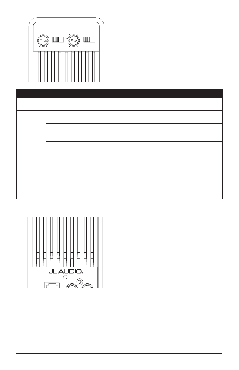
CONTROL PANEL SETTINGS
AND ADJUSTMENTS
Use the amplifier’s panel mounted settings and
controls to integrate and adjust the performance
of your subwoofer system to your vehicle and
listening preference.
50
80
125100
200
Low-Pass
Filter Freq. (Hz)
Turn-On
Mode
Remote
Level
Control
Low-Level Inputs
High-Level
Inputs
FUSE
(30A)
(
L
) (
R
)
Input
Sensitivity
Min. Max.
Signal
|
DC
|
Rem
0
|
180 deg.
+12 VDC GND Remote
Output
Polarity
Power Connections
Power
(green)
Protect
(red)
Switch Setting Mode / Function
Input
Sensitivity
Variable
Adjusts the input stage of the amplier to match the source unit’s output
voltage for maximum clean output (refer to Appendix A)
Turn-On
Mode
Rem
Conventional
(Preferred)
Connect to the source unit’s +12V remote turn-on output
DC
DC-Oset Sensing
(Auto)
Turns on and o by detecting the presence of small DC
signal in OEM audio outputs; connect to the source unit’s
high-level/speaker outputs
Signal
Signal
Sensing (Auto)
Turns on by detecting full-range audio signal in OEM
outputs; turns o after 30 seconds without signal;
connect to the source unit’s high-level/speaker outputs
Low-Pass
Filter Freq.
(Hz)
Variable
Adjusts the low-pass lter cuto frequency,
variable from 50-200 Hz, 12 dB/Octave
Output
Polarity
0 Normal speaker polarity
180 deg. Polarity reversed 180 degrees
STATUS LED / PROTECTION CIRCUITRY
A bi-color LED located on the amplifier panel is
used to indicate the amplifier’s operational status.
“Power (green)”: Lights up green to indicate
the amplifier is turned on and operating normally.
“Protect (red)”: Lights up red to indicate the
amplifier’s protection circuitry has been activated
due to thermal overload. When the protection
mode is activated, the amplifier outputs are muted
to protect its circuitry. When the amplifier cools,
the amplifier will return to its normal operation
and the LED will turn green.
50
80
125100
200
Low-Pass
Filter Freq. (Hz)
Turn-On
Mode
Remote
Level
Control
Low-Level Inputs
High-Level
Inputs
FUSE
(30A)
(
L
) (
R
)
Input
Sensitivity
Min. Max.
Signal
|
DC
|
Rem 0
|
180 deg.
+12 VDC GND Remote
Output
Polarity
Power Connections
Power
(green)
Protect
(red)
Loading ...
Loading ...
Loading ...