Before installing the indoor unit, you must choose an appropriate location. The following are standards that will help you choose an appropriate location for the unit:
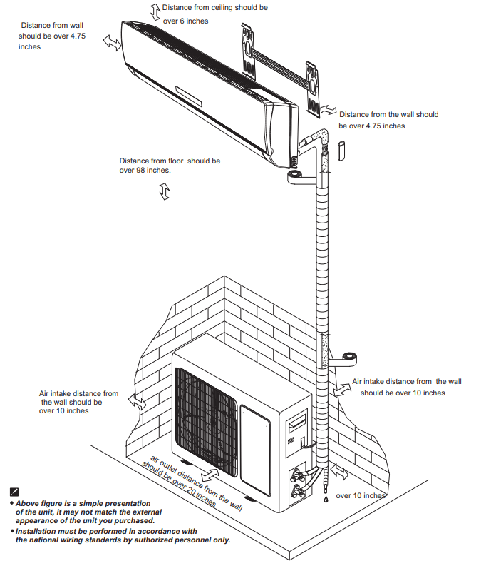
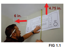
Find an area on an exterior wall, at least 6 inches from the ceiling and 4.75 inches from the adjacent wall. The location should also meet these standards:
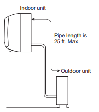
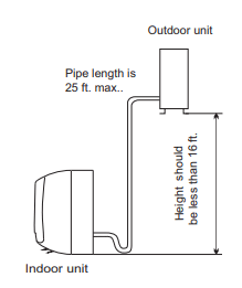
A location within 25 ft. of the outdoor condenser.
A space with good air circulation.
A space with convenient drainage for indoor condensate (tube that will go to the outside with the line set bundle).
A location where noise from the unit will not disturb you or others.
A wall strong enough to support the weight of the unit:
Use a stud finder to locate studs to ensure area is strong enough to support the unit
If a stud cannot be found in the desired area, you will need to use wall anchors
A location at least 3.5 feet from all other electrical devices (e.g., TV, radio, computer)
Do NOT install the unit in the following locations:
Near any source of heat, steam or combustible gases.
Near flammable items such as curtains or clothing. c Near any obstacles that might block air circulation.
Near a doorway.
In a location in direct sunlight
Note about the wall hole:
While choosing a location, be aware that you need to leave ample room for a wall hole to pass the communication cable and refrigerant piping (line set) that connect the indoor and outdoor units. The default position for all piping is the right side of the indoor unit (while facing the unit).
Choose where to install the outdoor condenser
Before installing the outdoor unit, you must choose an appropriate location. The following are standards that will help you choose an appropriate location for the unit:
• An area with good air circulation and ventilation.
• A firm and solid location to support the unit and prevent from vibration.
• An area where noise from the unit will not disturb you and others.
• An area protected or away from prolonged periods of direct sunlight or rain.
Do NOT install the unit in the following locations:
Near an obstacle that will block air inlets and outlets.
Near a public street, in alley ways, crowded areas or where noise from the unit will disturb others.
Near animals or plants that may be harmed by hot air discharge.
Near any source of combustible gas or flammable materials.
Near a heat source or ventilation fans.
In a location that is exposed to large amounts of dust.
In a location exposed to an excessive amount of salty air.
Special considerations for extreme weather:
If the condenser will be exposed to heavy wind:
Install unit so that air outlet fan is at a 90° angle (adjacent) to the direction of the wind. For extremely heavy winds, build a barrier in front of the condenser for added protection.
If the condenser will frequently be exposed to heavy rain or snow:
Build a shelter above the unit to protect it from rain or snow, be careful not to obstruct airflow around the unit.
Installation Instructions
1. Mark the wall using provided template
The mounting bracket is the device on which you will mount the indoor unit, it is the silver bracket on the back of the indoor unit. A mounting template has been provided to assist you with proper hole and evaporator (indoor unit) placement.
In the location chosen during pre-planning, locate studs in the wall using a stud finder. If you cannot find a stud, you will need to use wall anchors.
1. Place the mounting plate template against the wall, in a location:
On an exterior wall, at least 6 inches from the ceiling and 4.75 inches from adjacent wall (refer to figure 1.1)
Where two studs can be drilled directly into to support the mounting bracket
Where the line set hole, as marked on the template, will be free ofelectrical wiring, plumbing, and other sensitive components that may be hidden in the wall
NOTE: We strongly advise using the hole located on the right side of the template, as this is where the indoor unitwill have the line set bundle located. Ifyou choose to move the bundle to the left side of the unit, then you will need to make your line set connections inside, before mounting the unit.
2. Use a level to make sure your template is level.
3. Using something sharp like a nail, mark the areas of the wall where you will be drilling your screws and the line set hole.
4. Remove the mounting plate from the wall.
2. Install Wall Bracket
1. Detach the silver mounting bracket attached to the back of your indoor head unit.
2. Line up the bracket with the screw and hole locations marked previously on your wall.
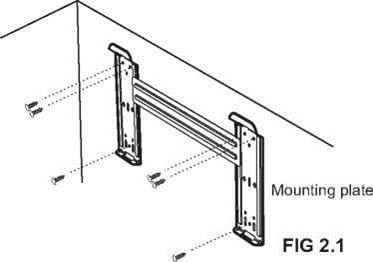
3. Mount the bracket on the wall using the 6 screws provided. Be sure that you are screwing directly into the two studs found earlier. If your wall does not have a stud, you will need to use wall anchors (Mollys) to secure the mounting bracket, (see figure 2.1)
CONCRETE OR BRICK WALLS:
If the wall is made of brick, concrete, or similar material, drill 5/64 in diameter holes in the wall and insert the sleeve anchors provided. Secure the mounting plate to the wall by tightening the screws directly into the wall anchors.
Note: The shape ofyour mounting plate may be different from the one above, but the installation method is similar.
3. Drill hole to pass the line-set bundle through the wall
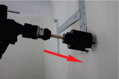
Using a 2.5 in. (63.5mm) core drill, drill a hole in the wall (Fig 3.1). Make sure that the hole is drilled at a slight downward angle so that the outdoor end of the hole is lower than the indoor end by about 1/2 in. (5 - 7mm) to ensure proper drainage for water condensation.
From the outside, place the protective wall cuff/ sleeve in the hole. This protects the edges ofthe hole and seals it when you finish the installation process.
4. Install the wall unit on the mounting bracket
The communication cable, the beginning ofthe drain tube and the beginning ofthe copper line set is inside an insulated sleeve attached to the back of the unit. You must prepare the bundle before passing it through the hole in the wall.
1. Grip the refrigerant copper piping at the base of the bend.
2. Slowly, with even pressure, bend the piping perpendicular to the head unit. Do not kink or damage the piping during the process.
3. CAUTION: Be extremely careful not to kink or damage the piping while bending them away from the unit. Any kinks in the piping will affect the unit's performance.
Preparing the Bundle
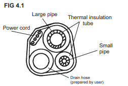
Before passing the refrigerant piping, drain hose and communication cable through the wall hole, you must bundle them together to save space. Make sure that the drain hose is at the bottom ofthe bundle. Putting the drain hose at the top of the bundle can cause the drain pan to overflow and backup, which can lead to fire, water damage or both. (FIG 4.1)
1. Double-check that the ends of the refrigerant pipes are sealed with blue and gray caps, preventing dirt orforeign materials from entering the pipes. Do not remove these caps.
2. Slowly pass the wrapped bundle of refrigerant pipes, drain hose, and communication cable through the hole in the wall. (FIG 4.2)
3. Hook the top of the indoor unit on the top hook of the mounting plate.
4. Check that the unit is hooked firmly on mounting plate by applying slight pressure to the left and right sides of the unit. The unit should not move or shift.
5. Using even pressure, push down on the bottom half of the unit. Keep pushing down until the unit snaps onto the hooks along the bottom ofthe mounting plate.
6. Double-check that the unit is firmly mounted by applying slight pressure to the left and the right sides ofthe unit.
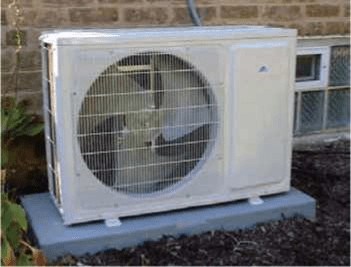
5. Secure the outdoor condenser
Anchor the Outdoor Unit
The outdoor unit can be anchored multiple ways* — a pad on the ground, a wall bracket, or a stand/blocks (*not included).
Installing the unit on a condenser pad:
Mark the positions of the four feet.
Pre-drill holes for expansion bolts, clean any dust away from holes.
Place a nut on the end of each expansion bolt.
Hammer expansion bolts into the pre- drilled holes.
Remove the nuts from expansion bolts. Place outdoor unit on bolts.
Put washer on each expansion bolt, then replace the nuts.
Using a wrench, tighten the nuts until snug.
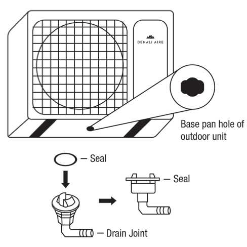
OPTIONAL: Install Drain Joint NOTE:
The drain joint cannot be used unless you are mounting the condenser on a wall bracket or blocks. The condenser must be elevated to accommodate the drain joint.
The drain joint is optional, if you would like to redirect water from the condenser to another location, install the drain joint.
The drain join only needs to be used if you need to redirect water.
Fit the rubber seal to the end of the drain joint that will connect to the outdoor unit.
Insert the drain joint into the hole in the base pan of the unit.
Rotate the drain joint 90° until it clicks in place facing the front of the condenser, away from the house.
Connect a 3/8” ID drain hose (not included) to the drain joint to redirect water from the condenser during heating mode.
FOR COLD CLIMATES
In cold climates, make sure that the drain hose is as vertical as possible to ensure swift water drainage. If water drains too slowly, it can freeze in the hose and flood the unit.
6 - 9: Unroll the line set, connect the copper refrigerant lines, remove condenser valve caps and open condenser valves
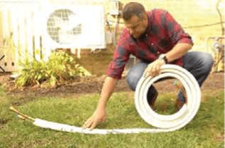
UNROLLING THE LINE SET:
Locate line-set box, remove it from the packaging.
Once out of the box, carefully unroll the line-set to its full extent.
CAUTION: Be extremely careful not to kink or damage the copper piping while unrolling the line set. Any kinks in the piping will affect the unit’s
Refrigerant Line Connections
QUICK CONNECT METHOD
Out of the box the system is setup for this method
Simply connect one end of the line set to the indoor unit
Install the included quick connect fittings to the outdoor unit
Simply connect the other end of the line set to the outdoor unit
The refrigerants lines are connected using the quick connect method described above
Refrigerant within the system is removed and recovered
A flare type line set can then be installed
Connect the one end of the flared line set to the indoor unit
Connect the one end of the flared line set to the outdoor unit
1. Remove the water tray on the outdoor unit.
2. Locate the 2 male condenser couplers that are inside the line set box. Screw the male condenser couplers on to the outdoor condenser until it stops — then give it another 1/4 turn making sure it Is fully secure.
3. Align the refrigerant pipes with the corresponding valves so they are not stressed. The caps are color coded to ensure the proper connection.
4. First, connect the line set to the indoor unit. Remove the caps according to color, 1 from the indoor unit, and 1 from the line set. Screw these together without cross threading them. Once they are tight, give another 1/4 turn to fully seat. Follow the same step to connect the other line.
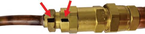
ATTENTION: Once you have made the connections from the line set to the indoor head, ensure that the black lines on the fittings are aligned. Ifthey are not you must re tighten them until they are aligned.
NOTE: the refrigerant lines must be connected to the valves on the outdoor unit and indoor unit with as little stress as possible, leave slack.
5. IMPORTANT: Cover up any exposed refrigerant lines with the optional extra foam insulation.
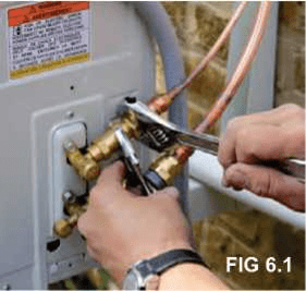
Now, connect the line set to the condenser. Tighten the bottom male condenser coupler first and then the top male condenser coupler using an open-ended wrench, (see figure 6.1)
Ensure the screw connectors do not skew as you tighten them. See below chart for proper torque.
IMPORTANT: Because the coupling works with tapping rings, it may leak if you undo and reconnect the lines — this will void the warranty.
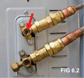
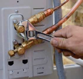
6. Remove the cover on the top valve using an adjustable wrench. Using a 5 mm Allen key, place key inside of the valve and turn counter clockwise slowly until you reach a stop (see figure 6.2). Then screw the cap back on the top of the valve and tighten to ensure a proper seal (see figure 6.3).
7. Remove the cover on the bottom valve using an adjustable wrench. Using a 5 mm Allen key, place key inside ofthe valve and turn counter clockwise slowly until you reach a stop. Then, screw the cover back on the top of the valve and tighten to ensure a proper seal.
8. After steps 1-7, double check that all connections are properly sealed using leak detection spray or soap suds. If bubbles form, the system has a leak and the screw connectors must be tightened again using an open-ended wrench, (see pg 17 for a description of the leak test)
10. Remove the electrical cover on the side of the condenser Remove the screws and electrical cover on the side of the condenser using a Philips screw driver.
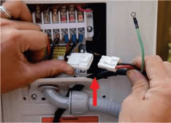
11. Connect the Molex plug 1. Connect your pre-installed communication wire from the indoor unit to the outside Molex plug. (FIG 11.1)
2. Be sure the wiring goes through one of the holes on the cover that was removed.
12. Connect the power supply NOTE: 9K&12K BTU systems are115-volt, 18K & 24K are 230-volt.
BEFORE PERFORMING ELECTRICAL WORK, READ THESE REGULATIONS
All wiring must comply with local and national electrical codes, and must be installed by a licensed electrician.
All electrical connections must be made according to the Electrical Connection Diagram located on the side panels ofthe indoor and outdoor units.
If there is a serious safety issue with the power supply, stop work immediately. Explain your reasoning to the client, and refuse to install the unit until the safety issue is properly resolved.
Power voltage should be within 90-110 of rated voltage. Insufficient power supply can cause electrical shock orfire.
If connecting power to fixed wiring, install a surge protector and main power switch with a capacity of 1.5 times the maximum current of the unit.
If connecting power to fixed wiring, a switch or circuit breaker that disconnects all poles and has a contact separation of at least 1/8 in. (3mm) must be incorporated in the fixed wiring. The qualified technician must use an approved circuit breaker or switch.
Only connect the unit to an individual branch circuit outlet. Do not connect another appliance to that outlet.
Make sure to properly ground the air conditioner.
Every wire must be firmly connected. Loose wiring can cause the terminal to overheat, resulting in product malfunction and possible fire.
Do not let wires touch or rest against refrigerant tubing, the compressor, or any moving parts within the unit.
If the unit has an auxiliary electric heater, it must be installed at least 40 in. (1 meter) away from any combustible materials.
CHOOSE THE RIGHT CABLE SIZE
The size of the power supply cable, signal cable, fuse, and switch needed is determined by the maximum current ofthe unit. The maximum current is indicated on the nameplate located on the side panel ofthe unit. Refer to this nameplate to choose the right cable, fuse, or switch.
Run powerfrom the disconnect box to the unit.
13. Connect the drain tube
Connect the drain tube that comes with the condenser, use duct tape to secure the tubes together.
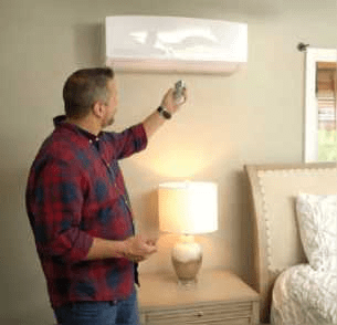
14. Go inside and turn on the wall unit 1. When the outside work has been concluded, be sure to re-check all wiring and valves\
2. Go inside and turn on the indoor unit using the provided remote control. (FIG 14.1)
3.Set the temperature to the lowest temperature in cool mode.
4. Wait for unit to run and assure unit blows cool air and all functions and mode are in working conditions
15. Check for leaks_ Once the unit is up and running it is important to checkfor refrigerant double check for leaks.
There are two methods to check for gas leaks:
Soap and Water Method: Fill a spray bottle with dish soap and water. Spray all line-set connection fittings to make sure there is no bubbling, bubbling implies there is a leak.
Leak Detector Method: When using a leak detector, please refer to the device's user manual for proper instructions.
Once confirmed that no leaks are present, replace the valve cover on the outside condenser.
16. Set up smart controls
Please refer to the Denali Aire Application installation manual forfurther instructions.
Maintenance
Front panel maintenance
1. Cut off the power supply
Turn off the appliance first before disconnecting) from the power supply.
Trouble
Analysis
Unit does not run
Is the air filter dirty?
Are the intakes and outlets ofthe air conditioner blocked?
Is the temperature set properly?
No cooled or heated air is coming out
Is the air filter dirty?
Are the intakes and outlets ofthe air conditioner blocked?
Is the temperature set properly?
Ineffective control
If strong interference (from excessive static electricity discharge, power supply voltage abnormality) presents, operation will be abnormal. At this time, disconnect from the power supply and connect back 2-3 seconds later.
Unit does not operate immediately
Changing modes during operation will cause a 3 minute delay.
Strange odor
This odor may come from another source such as furniture, cigarettes etc, which are sucked in to the unit and blows out with the air.
The sound of flowing water
Caused by the flow of refrigerant in the air conditioner, not an issue.
Defrosting sound in heating mode.
Cracking sound is heard
The sound may be generated by the expansion or contraction of the front panel due to changes in temperature.
Mist is spraying from the outlet
Mist appears when the room air becomes very cold because of cool air discharged from indoor unit during COOLING or DRY operation mode.
The compressor indicator (red) light is on constantly, and indoor fan stops.
The unit is shifting from heating mode to defrost. The indicator light will turn off within ten minutes and return to heating mode.