AP16872 (06/13)
!
FOR YOUR SAFETY!
— Do not store or use gasoline or other
flammable vapors and liquids or other
combustible materials in the vicinity of this or
any other appliance. To do so may result in an
explosion or fire.
— WHAT TO DO IF YOU SMELL GAS
● Do not try to light any appliance.
● Do not touch any electrical switch; Do not
use any phone in your building.
● Immediately call your gas supplier from a
neighbor’s phone. Follow the gas supplier’s
instructions.
● If you cannot reach your gas supplier, call the
fire department.
● Do not return to your home until authorized
by the gas supplier or fire department.
— Improper installation, adjustment, alteration,
service or maintenance can cause property
damage, personal injury, or death. Refer to
this manual. Installation and service must be
performed by a qualified installer, service
agency or the gas supplier.
WARNING: If the information in these instructions is not followed exactly, a fire or
explosion may result causing property damage, personal injury or death.
!
The purpose of this manual is twofold: one, to provide the installer with the basic directions
and recommendations for the proper installation and adjustment of the water heater; and two,
for the owner–operator, to explain the features, operation, safety precautions, maintenance and
troubleshooting of the water heater. This manual also includes a parts list.
It is very important that all persons who are expected to install, operate or adjust this water
heater read the instructions carefully so they may understand how to perform these operations.
If you do not understand these instructions or any terms within it, seek professional assistance.
Any questions regarding the operation, maintenance, service or warranty of this water heater
should be directed to the seller from whom it was purchased. If additional information is
required, refer to the section on “If You Need Service.”
Do not destroy this manual. Please read carefully and keep in a safe place for future
reference.
!
Recognize this symbol as an indication of Important Safety Information!
!
California Proposition 65 Warning: This product contains chemicals known to the
State of California to cause cancer, birth defects or other reproductive harm.
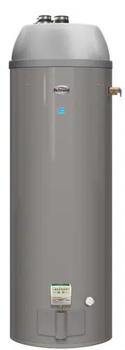
Residential 40 and 50 Gallon
Use & Care Manual
With Installation Instructions for the Installer
Printed in USA
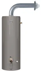
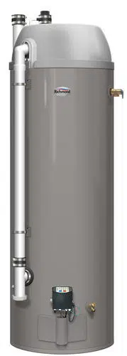
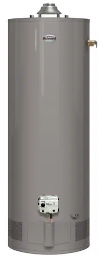
Direct Vent Water Heaters
Residential Gas - FVIR Certified
D
E
S
I
G
N
C
E
R
T
I
F
I
E
D
®
WARNING: This water heater is not
suitable for use in manufactured (mobile) homes!
CERTIFIED
R
!
2
Care and Cleaning
Draining ................ 23
Maintenance ............. 23
Burner Inspection ........ 24
Extended Shut-Down ......24
Safety Information
Safety Precautions ....... 3–6
LP Gas Models ........... 5
Installation Instructions
Location ................. 7
Venting ............... 9-12
Water Supply Connections .. 14
Gas Supply .............. 15
Heat Traps ...............16
Pipe Insulation ............17
Installation Checklist .......18
Potable/Space Heating .... 19
Operating Instructions
Lighting Instructions ...... 20
Water Temperature .... 21, 22
Troubleshooting Tips
Before You Call
For Service ........... 25, 26
Customer Service
Parts List ................ 27
If You Need
Service ................. 28
FOR YOUR RECORDS
Write the model and serial numbers here:
#
#
You can find them on a label on the appliance.
Staple sales slip or cancelled check here.
Proof of the original purchase date is needed to obtain service under
the warranty.
Inside you will find many helpful hints on how to use and
maintain your water heater properly. A little preventive care
on your part can save you time and money over the life of your
water heater.
You’ll find many answers to common problems in
the Troubleshooting Guide. If you review the chart of
Troubleshooting Tips first, you may not need to call for service.
READ THIS MANUAL
Your safety and the safety of others are very important. There
are many important safety messages in this manual and on your
appliance. Always read and obey all safety messages.
!
This is the safety alert symbol. Recognize this symbol
as an indication of Important Safety Information!
This symbol alerts you to potential hazards that can
kill or hurt you and others.
All safety messages will follow the safety alert symbol and
either the word “DANGER”, “WARNING”, “CAUTION” or
“NOTICE”.
These words mean:
!
DANGER:
An imminently hazardous situation
that will result in death or serious
injury.
!
WARNING:
A potentially hazardous situation that
could result in death or serious injury
and/or damage to property.
!
CAUTION:
A potentially hazardous situation that
may result in minor or moderate
injury.
NOTICE:
Attention is called to observe a
specified procedure or maintain
a specific condition.
READ THE SAFETY INFORMATION
3
Be sure to read and understand the entire Use and Care Manual before attempting to install or
operate this water heater. It may save you time and cost. Pay particular attention to the Safety
Instructions. Failure to follow these warnings could result in serious bodily injury or death. Should
you have problems understanding the instructions in this manual, or have any questions, STOP,
and get help from a qualified service technician, or the local gas utility.
IMPORTANT SAFETY INFORMATION
READ ALL INSTRUCTIONS BEFORE USING
Failure to install the venting system and properly vent the water heater to the
outdoors as outlined in the Venting Section of the Installation Instructions in this
manual can result in unsafe operation of the water heater. To avoid the risk of fire,
explosion, or asphyxiation from carbon monoxide, never operate this water heater
unless it is properly vented and has an adequate air supply for proper operation. Be
sure to inspect the vent system for proper installation at initial start-up; and at least
annually thereafter. Refer to the Care and Cleaning section of this manual for more
information regarding vent system inspection.
DANGER!
INSTALL THE VENTING SYSTEM AND PROPERLY VENT
THE WATER HEATER…
Gasoline, as well as other flammable materials and liquids (which include, but not
limited to adhesives, solvents, paint thinners etc.), and the vapors they produce are
extremely dangerous. DO NOT handle, use or store gasoline or other flammable
or combustible materials anywhere near or in the vicinity of a water heater and its
vent pipe terminal or any other appliance. Be sure to read and follow warning label
pictured below and other labels on the water heater, as well as the warnings printed
in this manual. Failure to do so can result in property damage, bodily injury or
death.
WARNING!
!
!
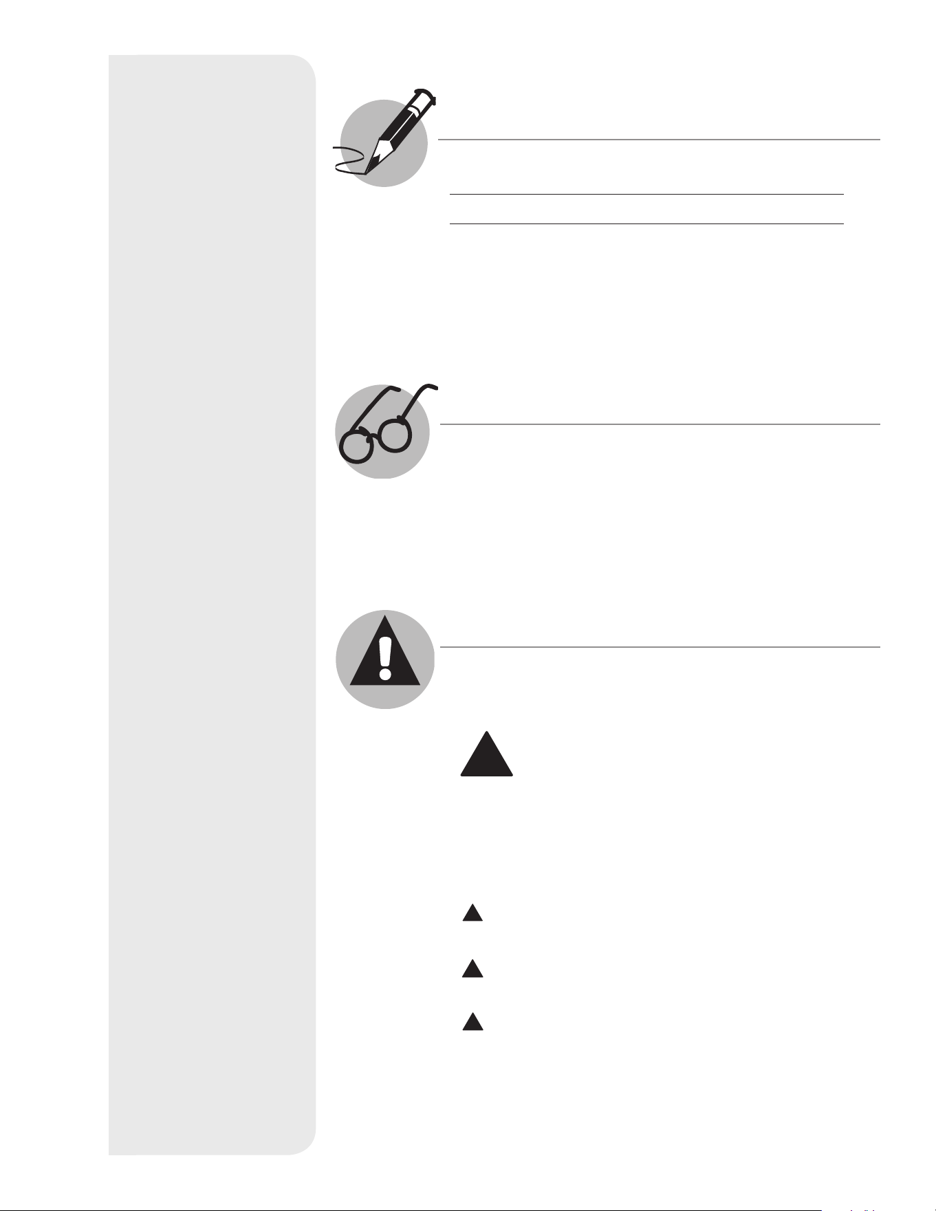
FLAMMABLES
Flammable Vapors
FIRE AND EXPLOSION HAZARD
Can result in serious injury or death.
Do not store or use gasoline or other flammable vapors and liquids
in the vicinity of this or any other appliance. Storage of or use of gasoline
or other flammable vapors or liquids in the vicinity of this or any other
appliance can result in serious injury or death.
W ARNING
4
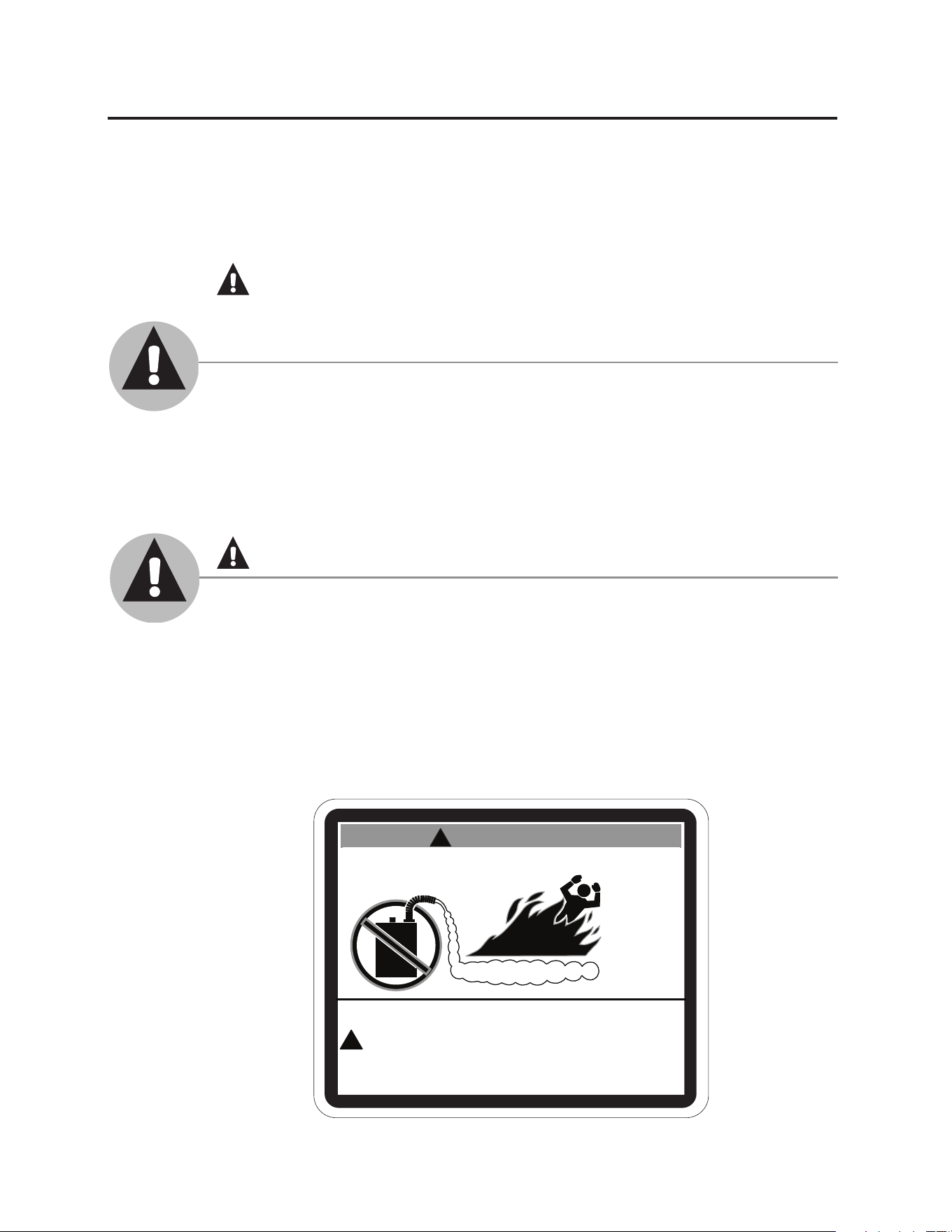
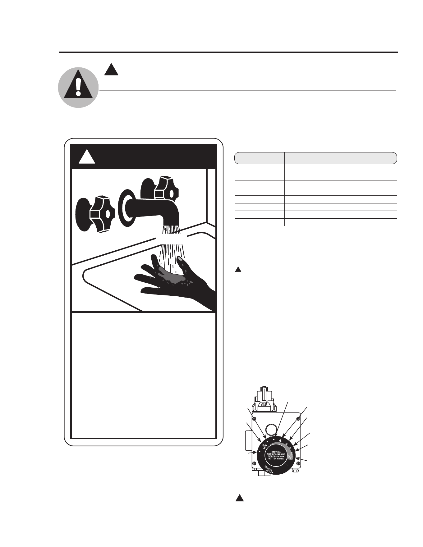
Time/Temperature Relationship in Scalds
Water Temperature Time To Produce a Serious Burn
120°F (49°C) More than 5 minutes
125°F (52°C) 1
1
/2 to 2 minutes
130°F (54°C) About 30 seconds
135°F (57°C) About 10 seconds
140°F (60°C) Less than 5 seconds
145°F (63°C) Less than 3 seconds
150°F (66°C) About 1
1
/2 seconds
155°F (68°C) About 1 second
Table courtesy of Shriners Burn Institute
The chart shown above may be used as a guide in
determining the proper water temperature for your
home.
DANGER: Households with small children, disabled,
or elderly persons may require a 120°F (49°C) or lower gas
control (thermostat) setting to prevent contact with “HOT”
water.
Maximum water temperatures occur just after the
burner has shut off. To find water temperature being
delivered, turn on a hot water faucet and place
a thermometer in the water stream and read the
thermometer. (See page 20 and 21 for more details.)
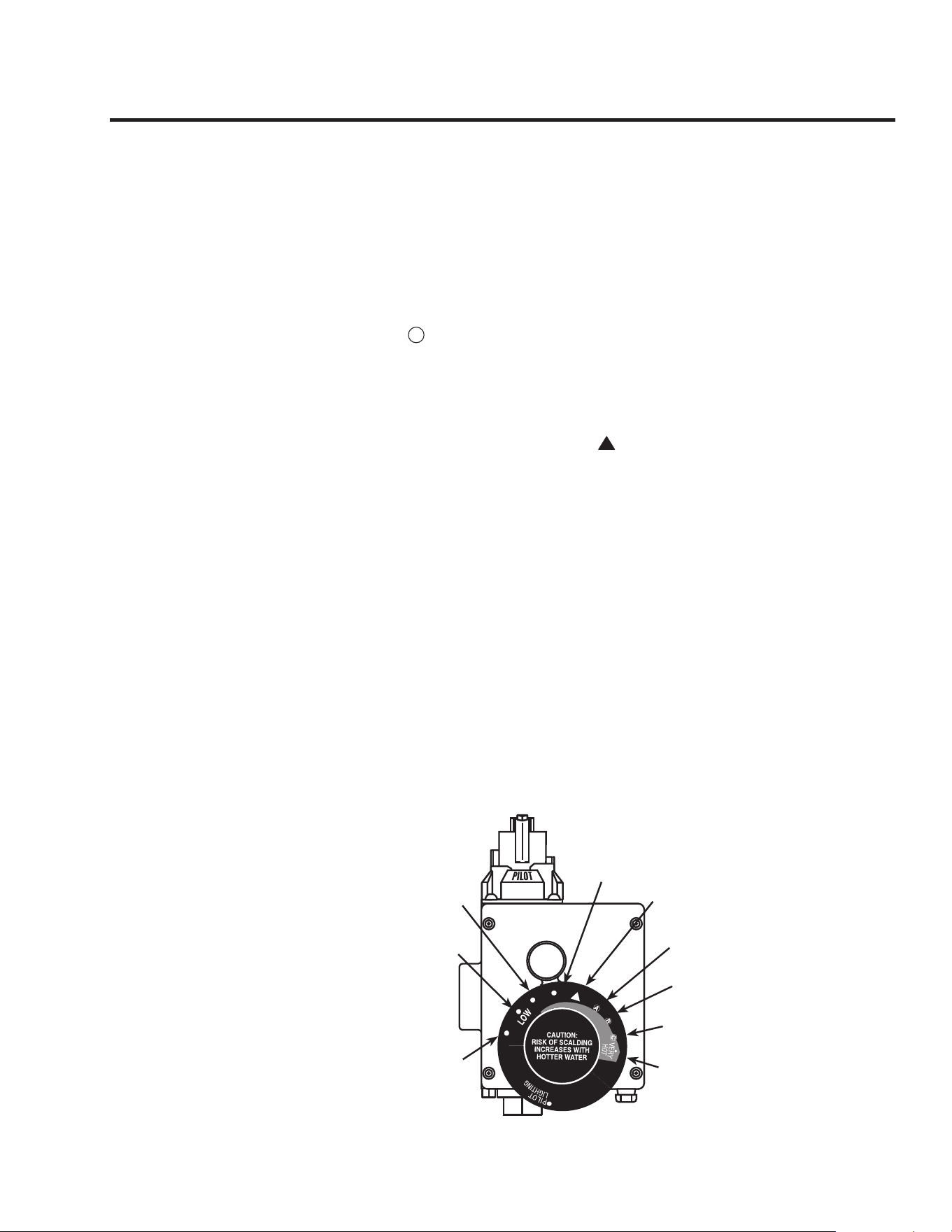
The temperature of the water in the heater can be
regulated by setting the temperature dial on the front
of the gas control (thermostat). To comply with
safety regulations the gas control (thermostat) was
set at its lowest setting
before the water heater
was shipped from the
factory.
The illustration at
the left details the
approximate water
temperature for each
mark on the Gas
Control (Thermostat)
Temperature Dial.
!
DANGER: Hotter water increases the potential for
Hot Water SCALDS.
DANGER
!
HOT
Water temperature over 125° F can
cause severe burns instantly or
death from scalds.
Children, disabled and elderly are
at highest risk of being scalded.
See instruction manual before
setting temperature at water
heater.
Feel water before bathing or
showering.
Temperature limiting valves are
available, see manual.
BURN
!
DANGER!
WATER TEMPERATURE SETTING
Safety and energy conservation are factors to be considered when selecting the water
temperature setting of a water heater’s gas control. Water temperatures above 125°F
(52°C) can cause severe burns or death from scalding. Be sure to read and follow the
warnings outlined on the label pictured below. This label is also located on the water
heater.
NOTICE: Mixing valves are recommended for reducing
point of use water temperature by mixing hot and
cold water in branch water lines. It is recommended
that a mixing valve complying with the Standard for
Temperature Actuated Mixing Valves for Hot Water
Distribution Systems, ASSE 1017 be installed. See pages
19 & 21 for more details and contact a licensed plumber
or the local plumbing authority for further information.
IMPORTANT SAFETY INFORMATION
READ ALL INSTRUCTIONS BEFORE USING
!
100°F
(38°C)
90°F
(32°C)
80°F
(27°C)
110°F
(43°C)
120°F
(49°C)
130°F
(54°C)
140°F
(60°C)
150°F
(66°C)
160°F
(71°C)
Temperatures are approximate
5
● Water heaters utilizing LP gas are
different from natural gas models. A
natural gas water heater will not function
safely on LP gas and vice versa.
● No attempt should ever be made to
convert the water heater from natural gas
to LP gas. To avoid possible equipment
damage, personal injury or fire, do not
connect the water heater to a fuel type
not in accordance with the unit data
plate. LP for LP units. Natural gas for
natural gas units. These units are not
certified for any other fuel type.
● LP appliances should not be installed
below grade (for example, in a basement)
if such installation is prohibited by
federal, state and/or local laws, rules,
regulations or customs.
● LP gas must be used with great caution.
It is heavier than air and will collect first
in lower areas making it hard to detect at
nose level.
● Before attempting to light the water
heater, make sure to look and smell for
gas leaks. Use a soapy solution to check
all gas fittings and connections. Bubbling
at a connection indicates a leak that must
be corrected. When smelling to detect a
gas leak, be sure to sniff near the floor
also.
● Gas detectors are recommended in LP
& natural gas applications and their
installation should be in accordance
with the detector manufacturer’s
recommendations and/or local laws, rules,
regulations or customs.
● It is recommended that more than one
method, such as soapy solution, gas
detectors, etc., be used to detect leaks in
gas applications.
!
DANGER: If a gas leak is present or
suspected:
● DO NOT attempt to find the cause
yourself.
● DO NOT try to light any appliance.
● DO NOT touch any electrical switch.
● DO NOT use any phone in your building.
● Leave the house immediately and make
sure your family and pets leave also.
● Leave the doors open for ventilation
and contact the gas supplier, a qualified
service agency or the fire department.
● Stay away from the house (or building)
until the service call has been made, the
leak is corrected and a qualified agency
has determined the area to be safe.
LP and Natural gas have an odorant added to aid in detecting a gas leak. Some people may
not physically be able to smell or recognize this odorant. If you are unsure or unfamiliar
with the smell of LP or natural gas, ask the gas supplier. Other conditions, such as “odorant
fade”, which causes the odorant to diminish in intensity, can also hide or camouflage a gas
leak.
DANGER!
LIQUEFIED PETROLEUM (LP PROPANE OR BUTANE)
AND NATURAL GAS MODELS
6
IMPORTANT SAFETY INFORMATION
READ ALL INSTRUCTIONS BEFORE USING
!
WARNING!
For your safety, the information in this manual must be followed to minimize the risk of
fire or explosion, electric shock, or to prevent property damage, personal injury, or loss of
life.
FOR INSTALLATIONS IN THE STATE OF CALIFORNIA
California Law requires that residential water heaters must be braced, anchored or
strapped to resist falling or horizontal displacement due to earthquake motions. For
residential water heaters up to 52-gallon capacity, a brochure with generic earthquake
bracing instructions can be obtained from: Office of the State Architect, 1102 Q Street,
Suite 5100, Sacramento, CA 95814 or you may call 916-445-8100 or ask a water heater
dealer.
However, applicable local codes shall govern installation. For residential water heaters of
a capacity greater than 52 gallons, consult the local building jurisdiction for acceptable
bracing procedures.
Have the installer show you the location of the gas shut-off valve and how to shut it off
if necessary. Turn off the manual shut-off valve if the water heater has been subjected to
overheating, fire, flood, physical damage or if the gas supply fails to shut off.
● Read this manual entirely before installing
or operating the water heater.
● Use this appliance only for its intended
purpose as described in this Use and Care
Manual.
● Be sure your appliance is properly installed
in accordance with local codes and the
provided installation instructions.
● DO NOT attempt to repair or replace
any part of your water heater unless it is
specifically recommended in this manual.
All other servicing should be referred to a
qualified technician.
SAFETY PRECAUTIONS
READ AND FOLLOW THIS SAFETY INFORMATION
CAREFULLY.
SAVE THESE INSTRUCTIONS
7
Installing the water heater
This water heater must be installed in accordance with these instructions, local codes, utility company
requirements, and/or in the absence of local codes, use the latest edition of the American National
Standard/National Fuel Gas Code. A copy can be purchased from either the American Gas Association,
400 N. Capitol Street NW, Washington, DC 20001 as ANSI standard Z223.1 or National Fire Protection
Association, 1 Batterymarch Park, Quincy, MA 02269 as booklet NFPA 54. For Canada Installations
use CAN/CSA B149 - Natural Gas and Propane Installation Code. A copy can be purchased from the
Canadian Standards Association, 178 Rexdale Boulevard,Toronto, Ontario, CANADA, M9W 1R3.
Location
The water heater should not be
located in an area where leakage
from the tank or connections
will result in damage to the area
adjacent to the heater or to lower
floors of the structure.
When such areas cannot be avoided
it is recommended that a suitable
catch pan, adequately drained, must
be installed under the water heater.
Catch pan kits are available from
the store where the water heater
was purchased, or any water heater
distributor.
Make certain that the floor underneath
the water heater is strong enough to
support the weight of the water heater
once it is filled with water.
A gas fired water heater or any other
appliance should not be installed in
a space where liquids which give off
flammable vapors are to be used or
stored. Such liquids include gasoline,
LP gas (butane or propane), paint or
adhesives and their thinners, solvents
or removers.
Because of natural air movement
in a room or other enclosed space,
flammable vapors can be carried some
distance from where liquids which
give off flammable vapors are to be
used or stored. The open flame of the
water heater’s pilot or main burner can
ignite these vapors.
FVIR certified gas water heaters can be
installed on a residential garage floor
without the use of an 18-inch stand in
accordance with the National Fuel Gas
Code, NFPA 54, ANSI Z223.1, for US
installations and in accordance with the
CAN/CSA B149.1 - Natural Gas and
Propane Installation Code for Canadian
installations, unless otherwise directed
by Province, State and Local code
requirements. The water heater must be
located so it is not subject to physical
damage, for example, by moving
vehicles, area flooding, etc.
● This water heater is of the direct
vent design. It therefore must be
located next to the outside wall,
within the range of the telescopic
adjustments. (See page 10 for
Locating Clearance Hole for Vent)
● Long hot water lines should be
insulated to conserve water and
energy.
● The water heater and water lines
should be protected from exposure
to freezing temperatures.
● DO NOT install the water heater in
unprotected outdoor areas.
● Minimum clearance from
combustible construction is 0”
sides, 0” rear; and 3” (7.6 cm)
from the front of the control. If the
clearances stated on the Instruction/
Warning Label, located on the front
of the heater differ, install the water
heater according to the clearances
stated on the label.
● The water heater may be installed
on combustible floors, but not
directly on carpeting. If the
water heater must be installed on
carpeting, place a metal or wood
panel beneath the water heater,
extending beyond its full width
and depth at least 3” (7.6 cm) in all
directions.
● If the water heater is installed in
an alcove or closet, the entire floor
must be covered by a wood or metal
panel. A minimum of 24” (61 cm)
clearance from the front and top
should be available for adequate
inspection and servicing.
!
WARNING:
Combustible construction
refers to adjacent walls and
ceilings and should not be
confused with combustible
or flammable products and
materials. Combustible
and/or flammable products
and materials should never
be stored in the vicinity of
this or any gas appliance.
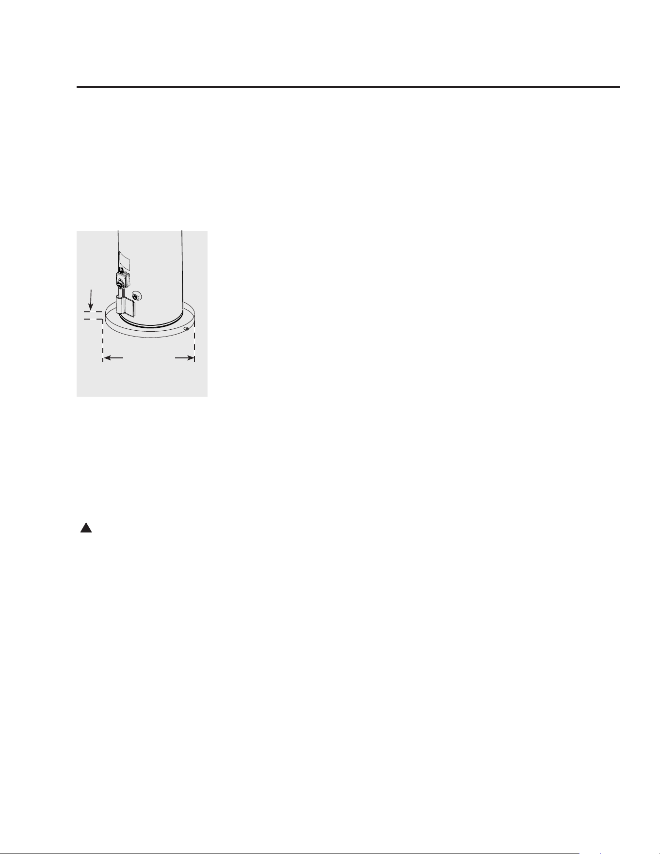
The auxiliary catch pan
installation MUST conform
to local codes.
Max. 2”
(5 cm)
Diameter of
water heater
plus 2” min.
(5 cm)

8
Installing the water heater
Combustion and Ventilation Air
Proper operation of the water
heater requires air for combustion
and ventilation. Provisions for
combustion and ventilation air must
comply with referenced codes and
standards.
NOTICE: If the water heater is
installed in an unconfined space
within a building of conventional
frame, masonry or metal
construction, infiltration air is
normally adequate for proper
combustion and ventilation. If
the water heater is installed in
a confined space, provisions for
ventilation air must be made.
All air for combustion and all products
of combustion are routed through the
ducting provided, directly from and to
the outside of the building.
NOTICE: If the duct openings
which supply ventilation air are
to be covered with a protective
screen or grill, the net free area
(openings in the material) of the
covering material must be used
in determining the size of the
openings. Protective screening for
the openings MUST NOT be smaller
than 1/4”mesh to prevent clogging
by lint or other debris.
Corrosive Atmospheres
The air in beauty shops, dry cleaning
establishments, photo processing
labs, and storage areas for liquid and
powdered bleaches or swimming
pool chemicals often contain such
halogenated hydrocarbons.
An air supply containing halogenated
hydrocarbons may be safe to breathe,
but when it passes through a gas flame
corrosive elements are released that
will shorten the life of any gas burning
appliance.
Propellants from common spray
cans or gas leaks from A/C and
refrigeration equipment are highly
corrosive after passing through a
flame.
The water heater warranty is voided
when failure of the heater is due to
operation in a corrosive atmosphere.
NOTICE: The water heater
should not be installed near
an air supply containing
halogenated hydrocarbons.
Inspect Shipment
Inspect the water heater and the
venting provided with the water
heater for possible damage. Check the
markings on the rating plate of the
water heater to be certain the type of
gas supplied corresponds to the water
heater requirements.

9
Direct Vent Terminal Clearances
D
V
V
E
FIXED
CLOSED
O
P
ERAB
LE
O
PERABLE
FIXED
CLOSED
v
v
B
L
F
C
B
v
v
v
X
B
B
B
A
J
B
I
H
X
v
M
K
v
G
A
V Vent Terminal X Air Supply Inlet
Area Where Terminal Is Not Permitted
Canadian Installations
1
US Installations
2
A - Clearance above grade, ve-
randa, porch, deck or balcony
1 ft. (30 cm) 1 ft. (30 cm)
B - Clearance to window or door
that may be opened
6 in. (15 cm) for appliances ≤ 10,000 Btuh (3 kW),
12 in. (30 cm) for appliances > 10,000 Btuh (3kW)
and ≤ 100,000 Btuh (30 KW), 36 in. (91 cm) for
appliances> 100,000 Btuh (30 kW)
6 in. (15 cm) for appliances ≤ 10,000 Btuh (3 kW), 9
in. (23 cm) for appliances > 10,000 Btuh (3kW) and
≤ 50,000 Btuh (15 KW), 1 ft. (30 cm) for appliances>
50,000 Btuh (15 kW)
C - Clearance to permanently
closed window
* *
D - Clearance to permanently
closed window
* *
E - Clearance to unventilated soft * *
F - Clearance to outside corner * *
G - Clearance to inside corner * *
H - Clearance to each side of cen-
ter line extended above meter/
regulator assembly
3 ft. (91 cm) within a height 15 ft (4.57m) above the
meter/regulator assembly*
*
I - Clearance to service regulator
vent outlet
3 ft. (1.83 m) *
J - Clearance to nonmechanical
air supply inlet to building or
the combustion air inlet to any
other appliance
6 in. (15 cm) for appliances ≤ 10,000 Btuh (3 kW),
12 in. (30 cm) for appliances > 10,000 Btuh (3kW)
and ≤ 100,000 Btuh (30 KW), 36 in. (91 cm) for
appliances> 100,000 Btuh (30 kW)
4 ft. (1.2 m) below or to side of opening; 1 ft. (300
mm) above opening
K - Clearance to a mechanical air
supply inlet
6 ft. (1.83 m) 3 ft. (91 cm) above if within 10 ft. (3 m) horizontally
L - Clearance above paved
sidewalk or paved driveway
located on public property
7 ft. (2.13 m)† *
M - Clearance under veranda,
porch, deck, or balcony
1 ft. (30 cm)‡ *
1
In accordance with the current
CSA B149.1 Natural Gas and Propane Installation Code
2
In accordance with the current
ANSI Z223.1/ NFPA 54 National Fuel Gas Code
† A vent shall not terminate directly above a sidewalk or paved driveway that is located between two single family dwellings and serves both dwellings.
‡ Permitted only if veranda, porch, deck, or balcony is fully open on a minimum of two sides beneath the oor.
* For clearances not specied in ANSI Z223.1/ NFPA 54 or CSA-B149.1, one of the following shall be indicated:
a) A minimum clearance value determined by testing in accordance with section 2.20, or;
b) A reference to the following footnote:
"Clearance in accordance with local installation codes and the requirements of the gas supplier."
10
The water heater must be installed with the factory supplied venting system. The old venting system (vent
pipe, air intake pipe, vent cap, elbows etc.) must be replaced with the vent system supplied with the new
water heater.
Venting
DANGER: Failure to install the
venting system and properly vent the
water heater to the outdoors as
outlined in the Venting section of this
manual will result in unsafe operation
of the water heater causing bodily
injury, explosion, fire or death. To
avoid the risk of fire, explosion, or
asphyxiation from carbon monoxide,
NEVER operate the water heater unless
it is properly vented and has adequate
air supply for proper operation as
outlined in the Venting section of this
manual.
CAUTION: If there are any
damaged parts, DO NOT install the
water heater. Report any damage to
your distributor or to the carrier.
NOTICE: The four fasteners that
are required to secure the vent cap
to the external wall are not provided.
These should be screw type (not nails)
chosen for the type of construction and
obtained locally
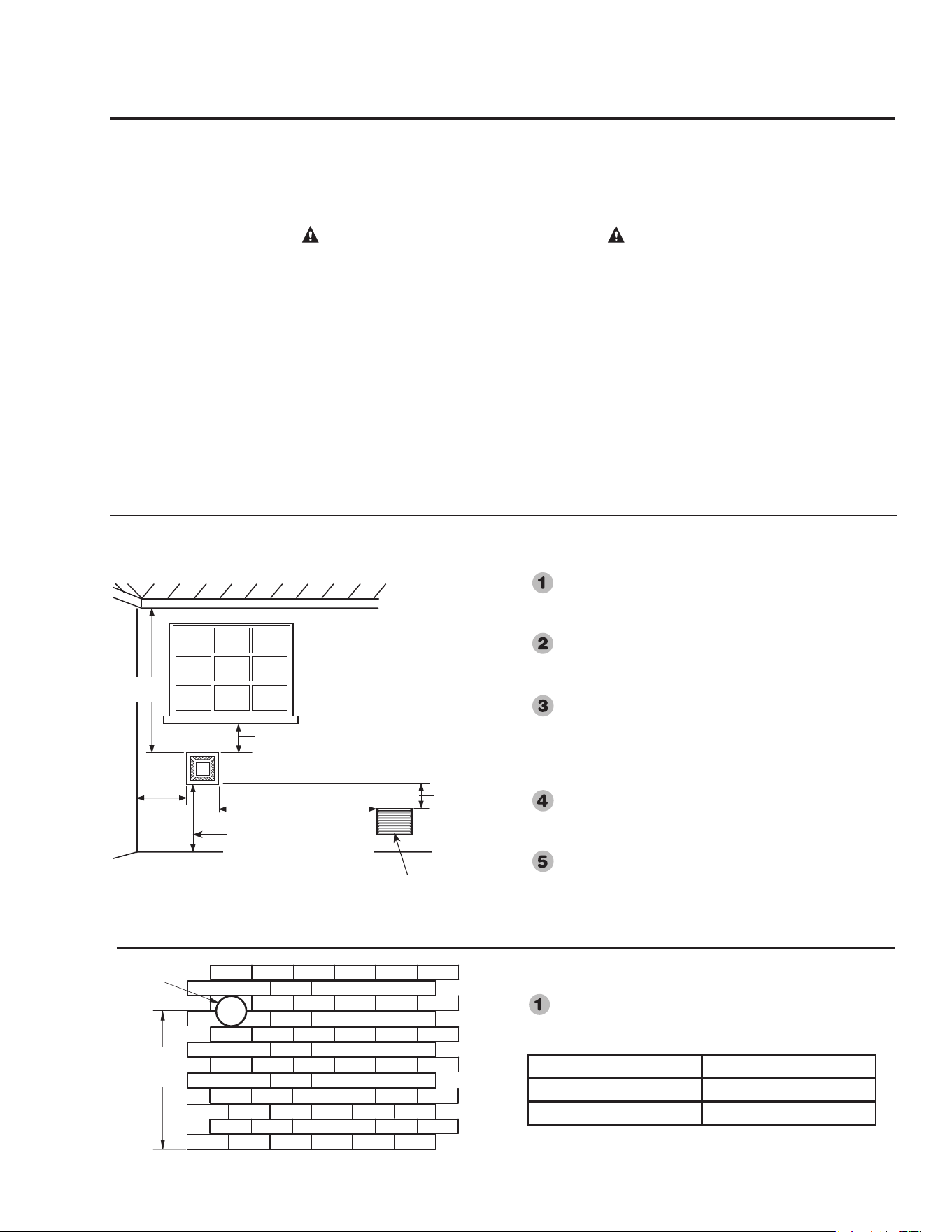
Vent Terminal must be located at least
12” (30.5 cm)
min. above grade level and above normal snow
levels. Higher in areas of heavy snowfall.
Vent Terminal must be located at least 9” (23 cm)
from windows, doors, or any other opening through
which flue gases could enter the building.
Vent Terminal must be located at least 36” (91 cm)
above any Forced Air Inlet into the building within
10’ (3 m) of the Vent Terminal.
Any fresh or make-
up air inlet such as for a dryer or furnace area is
considered to be a forced air inlet.
Vent Terminal must be located at least 18” (46 cm)
from any overhang or building corner or other
irregularity.
DO NOT locate the Vent Terminal under any deck
or patio structure.
"X"
Floor
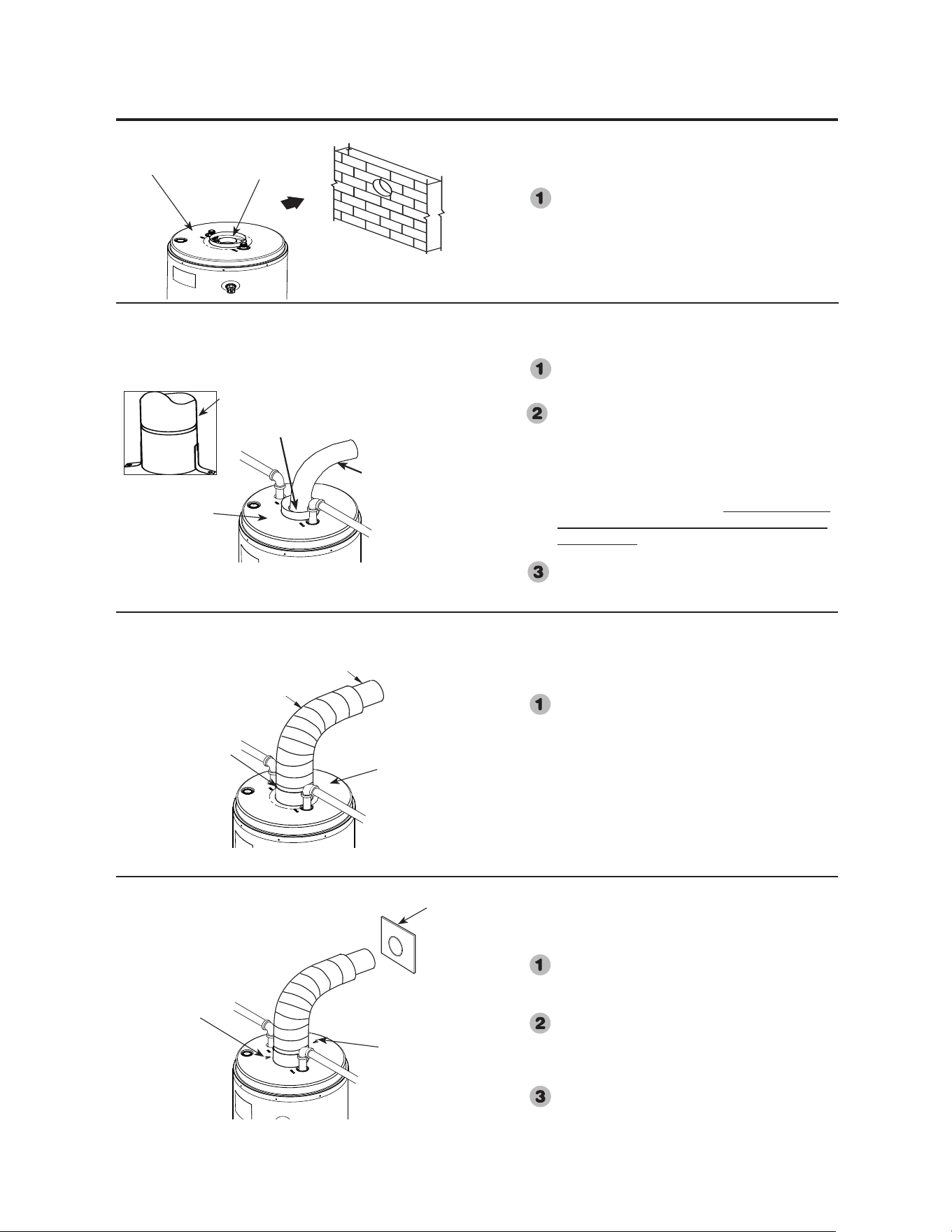
Cut a clearance hole, approximately 6 1/4” (15.8 cm) in
diameter, through the exterior wall for the 6” (15.2 cm)
diameter air tube.
Capacity "X"
40 Gallon 68-1/4" (173.3 cm)
50 Gallon 68" (172.7 cm)
Approximately
6 1/4" Diameter
(15.8 cm)
Locating Clearance Hole for Vent
Vent Termination Clearances
HOT
9" Min. (23 cm)
Within 10 feet(305 cm)
Any forced air inlet
into the building
18”Min
(46 cm)
36” Min.
(91 cm)
18”Min.
(46 cm)
12" Min. (30 cm) above grade
(Higher in areas of heavy
snowfall.)
Inside
Corner
See the back page of this manual
for additional requirements for the
Commonwealth of Massachusetts.
Installing the Water Heater
11
3" (7.6 cm) (90° Elbow (Steel)
6" (15.2 cm)
90° Elbow (Aluminum)
Installing 6” (15.2 cm) Diameter
Aluminum Elbow
Install the 6” (15.2 cm) aluminum elbow over
the 3” (7.6 cm) steel elbow. Be certain both
are pointed in the desired direction with the 3"
(7.6 cm) centered inside the 6” (15.2 cm) inch
elbow.
3" (7.6 cm) 90° Elbow (Steel)
Bend the brackets on the elbow as shown on
left.
Place the 3” (7.6 cm) steel elbow on the water
heater flue pipe and press it firmly downward
until fully seated and pointed in the desired
direction. After installation of elbow, apply
silicone sealant around the outside of the
pipe where the 3" (7.6 cm) elbow
comes in
contact with the ue pipe
. An improper seal
can cause product performance and nuisance
pilot outages.
Secure the 3" (7.6 cm) steel elbow to the top
pan by inserting two #8 x 3/8" long screws
supplied through the bent brackets.
Moving water heater to its final
location
Installing 3” (7.6 cm) Diameter
Steel Elbow
Move the water heater to its final installed
location. Make certain clearances from
combustible materials are observed.
‡ Sheet Metal Screws
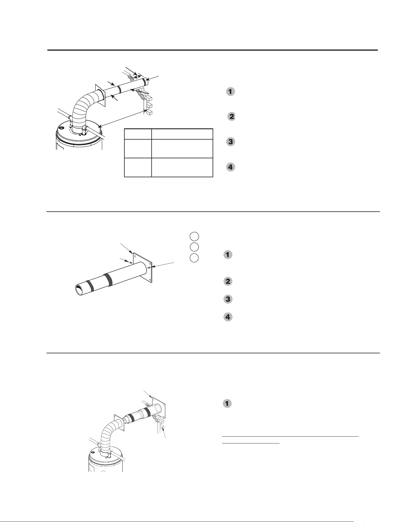
Leveling and attaching 6” (15.2
cm) Diameter Aluminum Elbow
As an aid to leveling the 6” (15.2 cm) elbow,
temporarily place the 6” (15.2 cm) sliding tube
onto the elbow.
When leveled, drill a
1
/
8
”
inch diameter hole
through the elbow into the collar at the front and
back. Secure with the two #8 sheet metal screws
supplied.
Place the finishing collar on the 6” (15.2 cm)
elbow, as it will be positioned later.
‡
‡
Install end of elbow
with label to top
plenum.
Top Plenum.
Finishing
Collar
Top Plenum
Top Pan
Elbow with brackets bent at 90°
Top Plenum
* Seal with silicone sealant.
12
H1
Outside
Wall
Vent Terminal Base (Outside)
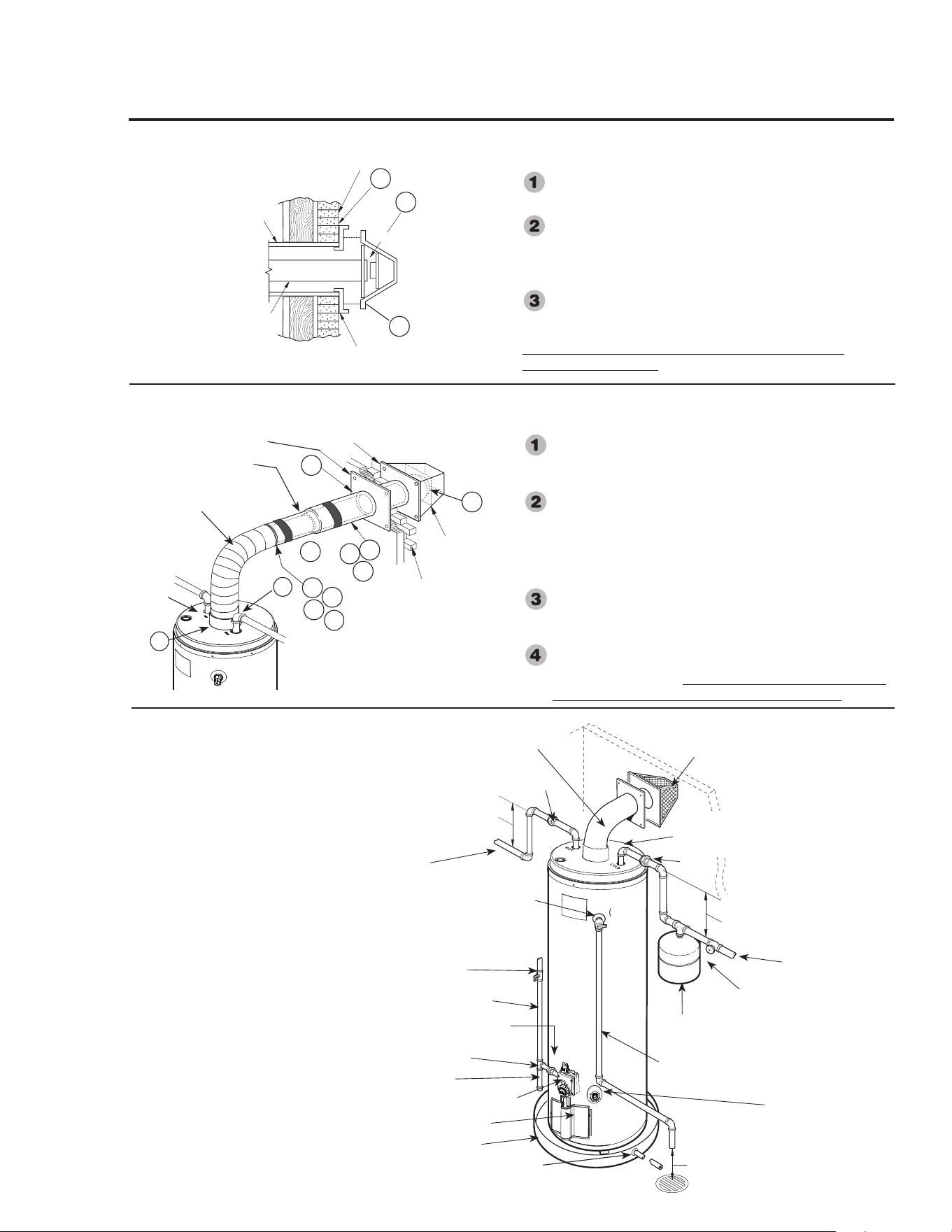
Attaching the 6” (15.2 cm) Diameter
Main Tube
From the outside of the building, insert the
6” (15.2 cm) vent tube/base assembly through the
hole in the exterior wall and onto the 6” (15.2 cm)
elbow. Slide as needed into place. (H1).
An improper seal can cause product performance and
nuisance pilot outages.
✚
✚
✚
✚
✚
✚
G1
G2
G3
Sheet Metal Screws &
Silicone Sealant
Vent Terminal Base (Outside)
Assembling the 6” (15.2 cm) Diameter
Vent Tube Assembly w/ vent terminal
base.
Inspect the vent tube upon opening the kit to assure
two silicone sealing bands are included and
positioned at the sealing points.
Attach the outer 6” (15.2 cm) main tube to the vent
terminal base as shown on left. (G1)
Drill a
1
/
8
”
inch diameter hole through the tube and the
collar of the base. (G2)
Secure with a #8 sheet metal screw, supplied. Repeat
with a second hole and screw approximately 180°
from the first. (G3)
Placing 3" (7.6 cm) Diameter Main
Vent Tube through Exterior Wall
Inspect the vent tube upon opening the kit to assure
three silicone sealing bands are included and
positioned at the sealing points.
Install the 3" main vent tube onto the end of the 3"
inner elbow & seal with silicone band by folding the
band back over the seam of both tubes.
Extend the 3” (7.6 cm) tube assembly to its required
length. Be sure a minimum of 2 1/2" extends beyond
the outer wall. (F1)
Move high temperature silicone band to connecting
joints as shown. (F2)
F2
"X" Optional kit that provides additional adjustment up to 48" (121.9 cm) can be purchased seperately.
"X"
Gallons "X" Inches (cm)
40 9 1/8" (23.17 cm) -
19 1/8" (48.57 cm)
50 8 1/8" (20.63 cm)
- 18 1/8" (46 cm)
2 1/2" Minimum extension
beyond wall.
Installing the water heater
F4
3" Tube
F1
13
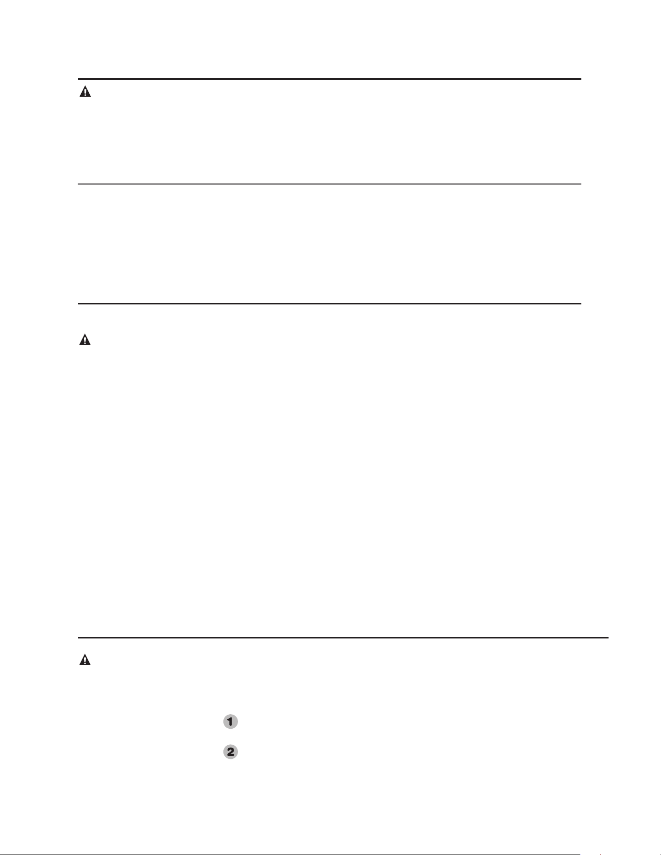
Typical Installation
Heat Trap
6" Min (15.2 cm).
Vent Terminal Cap
(Outside)
Heat Trap
6" Min. (15.2 cm)
Hot Water
Outlet to
Fixtures
To Cold Water Supply
Temperature
and Pressure
Relief Valve
Relief Valve Discharge Line
to Suitable Open Drain
Expansion Tank
(if required)
Manual Gas Shut-Off
Shut-Off Valve
To Gas Supply
Ground Joint Union
Gas Control (Thermostat)
Jacket Door
Drain Valve
Auxiliary Catch Pan
Air Gap - 6" (15.2 cm)
Cap
Air Tube
Sediment Trap
Union
Anode Rod (Located under top pan) Not
accessible. Refer to Protection Plus Kit for
additional protection.
Catch Pan Pipe to suitable drain.
✚
✚
*
✚
✚
✚
✚
✚
✚
✚✚✚
✚✚✚
*
*
✚✚✚
*
J3
J1
J2
L5
L1
K
*
Screw Anchors
Wall
Vent Terminal Base
3" Tube
(7.6 cm)
6" Tube
(15.2 cm)
Seal with Silicone Sealant
Vent Terminal Base (Outside)
Finishing Collar (Inside)
6
” (15.2 cm)
90° Elbow
(Aluminum)
Outside Wall
Vent Terminal
Cap (Outside)
✚✚✚
L2
L3
L2
L3
✚
✚
Sheet Metal Screws
▲Seal with Silicone Band
Securing Vent Cap / Base Assembly to
the Exterior Wall
Next place the 3” (7.6 cm) main tube fully onto the collar
of the vent cap. Then seat the cap against the base. (J1)
Secure the vent cap/base assembly to the exterior wall
with four screw anchors appropriate for the type of wall
construction. The 6” (15.2 cm) tube should be essentially
level. However, a small amount of upward pitch will not
affect operation. (J2)
Caulk the junctions of the vent terminal base and the
exterior wall with silicone sealant (Not Supplied). (J3)
An improper seal can cause product performance and
nuisance pilot outages.
Final Assembly and Sealing of the Vent
System
Position and fasten the finishing collar, previously
installed on the 6” (15.2 cm) elbow, against the wall to
close the opening around the tube. (K)
Make certain the 6” (15.2 cm) inner sliding air tube has
been fully engaged onto the 6" (15.2 cm) elbow.(L1)
Drill two 1/8” inch holes (180° apart) in the junction of
the two joints in the 6" (15.2 cm) tube. (L2)
Fasten with four #8 sheet metal screws supplied. (L3)
Using a flat head screw driver inserted through the holes
in the vent cap, roll the silicone band over the seam to
seal. (L4)
Seal all the 6” (15.2 cm) tube joints with the silicone
bands provided (L5). Seal the elbow joint to the plenum
using silicone sealant. Again, an improper seal can cause
product performance and nuisance pilot outages.
NOTICE: The National
Fuel Gas Code (NFGC)
mandates a manual gas
shut-off valve: See (NFGC)
for complete instructions.
Local codes or plumbing
authority requirements may
vary from the instructions
or diagrams provided and
take precedent over these
instructions.
6" Inner Sliding Tube
Top of
Plenum
✱Seal with Silicone Sealant
✱
L4
✱
▲
Union
▲

14
A new combination temperature and pressure relief valve, complying with the Standard for Relief Valves
and Automatic Gas Shut-Off Devices for Hot Water Supply Systems, ANSI Z21.22, is supplied and must
remain in the opening provided and marked for the purpose on the water heater. No valve of any type
should be installed between the relief valve and the tank. Local codes shall govern the installation of relief
valves.
Relief Valve
The pressure rating of the relief valve
must not exceed 150 PSI (1034 kPa), the
maximum working pressure of the water
heater as marked on the rating plate.
The Btuh rating of the relief valve must
equal or exceed the Btuh input of the water
heater as marked on its rating plate.
Position the outlet of the relief valve above
a suitable open drain to eliminate potential
water damage. Piping used should be of a
type approved for hot water distribution.
The discharge line must be no smaller
than the outlet of the valve and must
pitch downward from the valve to allow
complete drainage (by gravity) of the relief
valve and discharge line.
The end of the discharge line should not
be threaded or concealed and should be
protected from freezing. No valve of any
type, restriction, or reducer coupling should
be installed in the discharge line.
Thermal Expansion
Determine if a check valve exists in the inlet
water line. Check with your local water utility
company. It may have been installed in the cold
water line as a separate back flow preventer,
or it may be part of a pressure reducing valve,
water meter or water softener. A check valve
located in the cold water inlet line can cause
what is referred to as a “closed water system”.
A cold water inlet line with no check valve or
back flow prevention device is referred to as an
“open” water system.
As water is heated, it expands in volume and
creates an increase in the pressure within the
water system. This action is referred to as
“thermal expansion”. In an “open” water
system, expanding water which exceeds the
capacity of the water heater flows back into the
city main where the pressure is easily dissipated.
A “closed water system”, however, prevents
the expanding water from flowing back into the
main supply line, and the result of “thermal
expansion” can create a rapid and dangerous
pressure increase in the water heater and
system piping. This rapid pressure increase can
quickly reach the safety setting of the relief
valve, causing it to operate during each heating
cycle. Thermal expansion, and the resulting
rapid, and repeated expansion and contraction
of components in the water heater and piping
system can cause premature failure of the relief
valve, and possibly the heater itself. Replacing
the relief valve will not correct the problem!
The suggested method of controlling thermal
expansion is to install an expansion tank in the
cold water line between the water heater and the
check valve (see illustration on page 12). The
expansion tank is designed with an air cushion
built in that compresses as the system pressure
increases, thereby relieving the over pressure
condition and eliminating the repeated operation
of the relief valve. Other methods of controlling
thermal expansion are also available. Contact
your installing contractor, water supplier or
plumbing inspector for additional information
regarding this subject.
Refer to the illustration on page 9 for
suggested typical installation. The
installation of unions or flexible copper
connectors is recommended on the hot and
cold water connections so that the water
heater may be easily disconnected for
servicing if necessary. The HOT and COLD
water connections are clearly marked and
are 3/4” NPT on all models. Install a shut-
off valve in the cold water line near the
water heater.
Water Supply Connections
NOTICE: DO NOT apply
heat to the HOT or COLD
water connections. If sweat
connections are used, sweat
tubing to adapter before
fitting adapter to the water
connections on heater.
Any heat applied to the
water supply fittings will
permanently damage the dip
tube, nipples and/or heat
traps.
Installing the water heater
15
WARNING: DO NOT
attempt to convert this water
heater for use with a
different type of gas other
than the type shown on the
rating plate. Such conversion
could result in hazardous
operating conditions.
Leak Testing
The water heater and its gas
connections must be leak tested at
normal operating pressures before it is
placed in operation.
Turn on the manual gas shut-off
valve near the water heater.
Use a soapy water solution to test
for leaks at all connections and
fittings. Bubbles indicate a gas
leak that must be corrected.
The factory connections to the gas
control (thermostat) should also be leak
tested after the water heater is placed in
operation.
Gas Supply
The branch gas supply line to the water
heater should be clean 1/2” black steel
pipe or other approved gas piping
material.
A ground joint union or ANSI design
certified semi-rigid or flexible gas
appliance connector should be installed
in the gas line close to the water heater.
A manual gas shut-off valve should be
at least 5 ft. (1.5 m) above the floor and
readily accessible.
Use compound sparingly on male
threads only. The compound used on
threaded joints of the gas piping must
be of the type resistant to the action of
LP gas.
Where a sediment trap is not
incorporated as part of the appliance,
a sediment trap shall be installed
downstream of the equipment shutoff
valve as close to the inlet of the
appliance as practical at the time the
appliance installation. The sediment
trap shall be either a tee fitting with a
capped nipple in the bottom outlet or
other device recognized as an effective
sediment trap.
DO NOT use excessive force (over
31.5 ft lbs.) (42.7 Nm) in tightening
the pipe joint at the gas control
(thermostat) inlet, particularly if teflon
pipe compound is used, as the valve
body may be damaged.
The inlet gas pressure to the water
heater must not exceed 10.5” w.c.
(2.65 kPa) for natural gas or 14" w.c.
(3.5 kPa) for LP gas. For purposes of
input adjustment, the minimum inlet
gas pressure (with main burner on) is
shown on the water heater rating plate.
If high or low gas pressures are present,
contact your gas supplier for correction.
● If flexible connectors are used, the
maximum length shall not exceed
36” (91 cm).
● If lever type gas shut-offs are used,
they shall be T-Handle type.
WARNING: Never use
an open flame to test for
gas leaks, as property
damage, personal injury, or
death could result.
Condensation
Condensation can form on the tank
when it is first filled with water.
Condensation might also occur with
a heavy water draw and very cold
inlet water temperatures.
Drops of water falling on the burner
can produce a sizzling or pinging
sound. The water may also be seen
beneath the water heater.
This condition is not unusual, and will
disappear after the water becomes
heated. If, however, the condensation
continues, examine the piping and
fittings for possible leaks.
To Fill the Water Heater
Make certain that the drain valve is
closed, then open the shut-off valve in
the cold water supply line.
Open each hot water faucet slowly to
allow the air to vent from the water
heater and piping.
A steady flow of water from the hot
water faucet(s) indicates a full water
heater.
WARNING: The tank
must be full of water before
heater is turned on. The
water heater warranty does
not cover damage or failure
resulting from operation
with an empty or partially
empty tank.
16
Insulation Blankets
Insulation blankets, available to the general
public, for external use on gas water
heaters are not necessary. The purpose
of an insulation blanket is to reduce the
standby heat loss encountered with storage
tank heaters. This water heater meets or
exceeds the National Appliance Energy
Conservation Act standards with respect to
insulation and standby loss requirements
making an insulation blanket unnecessary.
The manufacturer’s warranty does not
cover any damage or defect caused by
installation, attachment or use of any type
of energy saving or other unapproved
devices (other than those authorized
by the manufacturer) into, onto or in
conjunction with the water heater. The use
of unauthorized energy saving devices may
shorten the life of the water heater and may
endanger life and property.
The manufacturer disclaims any
responsibility for such loss or injury
resulting from the use of such unauthorized
devices.
CAUTION: If local codes require the
application of an external insulation
blanket to this water heater, pay careful
attention to the following so as not to
restrict the proper function and
operation of the water heater:
● DO NOT cover the operating or warning
labels attached to the water heater or
attempt to relocate them on the exterior
of insulation blanket.
DO NOT apply insulation to the top of
the water heater as this will interfere with
the safe operation of the water heater and
venting system.
DO NOT cover the burner access door,
jacket door, gas control (thermostat)/gas
valve or pressure and temperature relief
valve.
WARNING: If local
codes require external
application of insulation
blanket kits the
manufacturer’s instructions
included with the kit must
be carefully followed.
High Altitude
Ratings of gas appliances are based on sea
level operation. This water heater is suitable
and certified for use at high altitudes. Refer
to the altitude label on the water heater for
maximum allowable installation altitude
Please contact your local distributor or
place of purchase for a high altitude model.
WARNING: Failure to install a water
heater suitable for the altitude at the
location it is intended to serve, can
result in improper operation of the
appliance resulting in property damage
and/or, producing carbon monoxide gas,
which could result in personal injury, or
death.
Pressure Testing the Gas Supply System
The water heater and its manual gas shut-
off valve must be disconnected from the
gas supply piping system during any
pressure testing of that system at pressures
in excess of 1/2 psi (14” w.c.).
The water heater must be isolated from
the gas piping system by closing the
manual gas shut-off valve during any
pressure testing of the gas supply piping at
pressures equal to or less than
1/2 psi (14” w.c.).
Heat Trap
For increased energy efficiency, some water
heaters have been supplied with factory
installed 3/4” NPT heat traps in the hot
outlet line and cold water inlet line.
NOTICE: DO NOT apply heat to the
HOT or COLD water connections. If
sweat connections are used, sweat tubing
to adapter before fitting adapter to the
water connections on heater. Any heat
applied to the water supply fittings
will permanently damage the dip tube,
nipples, and/or heat traps.
Installing the water heater
17
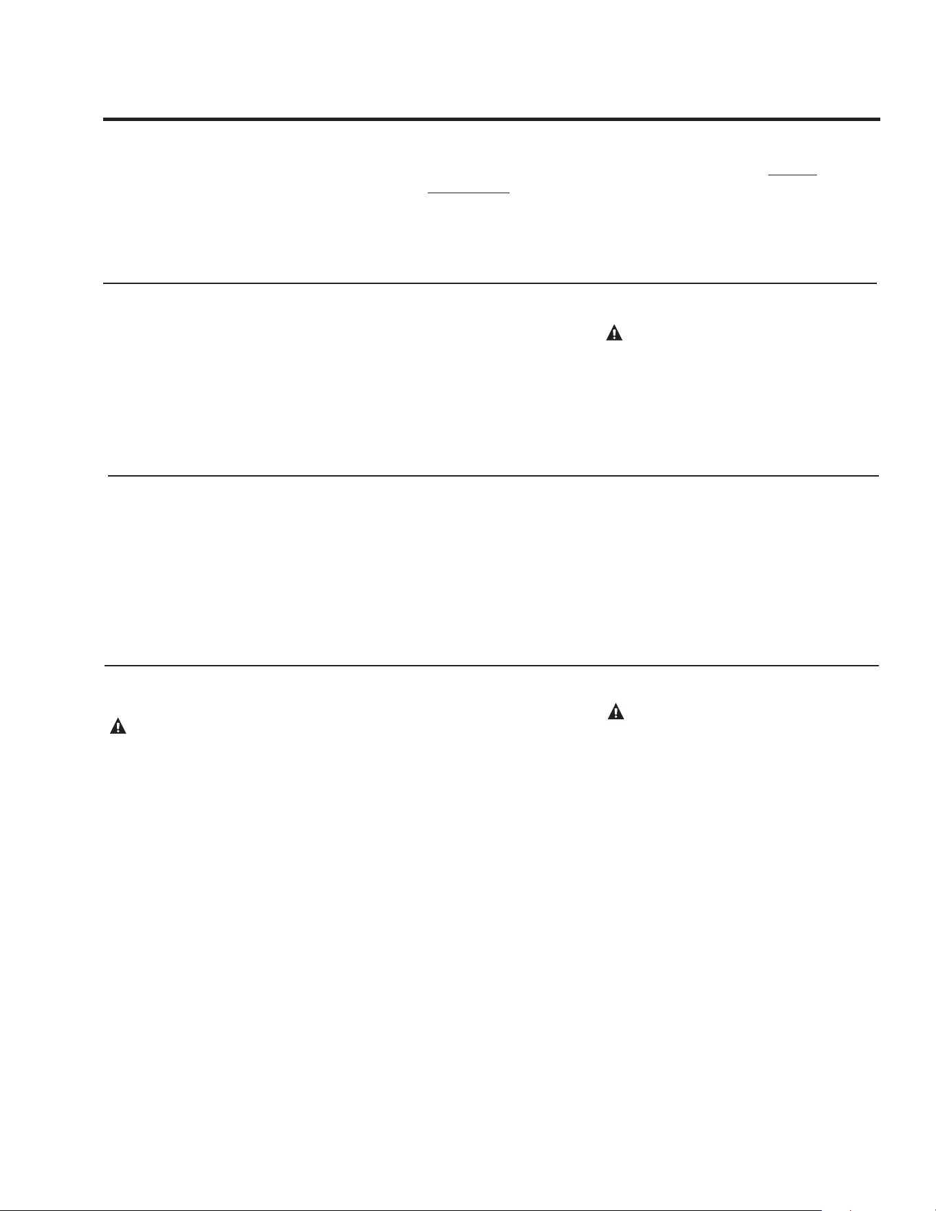
For increased energy efficiency, some
water heaters have been supplied with two
24” (60.9 cm) sections of pipe insulation.
Please install the insulation, according to
the illustrations above, that best meets your
requirements.
DO
❑ DO check inlet gas pressure to ensure that
it is within the range specified on the rating
plate.
❑ DO provide adequate air for combustion
and ventilation as discussed in the Use and
Care Manual and the National Fuel Gas
Code.
❑ DO maintain proper clearances to
combustibles as specified on the instruction/
warning label.
❑ DO ensure that the venting system
complies with the guidelines found in the
Use and Care Manual and National Fuel Gas
Code.
❑ DO contact a qualified service technician
if the pilot or main burner will not stay lit.
DON’T
❑ DON’T block or restrict the vent terminal.
❑ DON’T remove the Burner Access Door
unless absolutely necessary. This should only
be done by a qualified service technician.
A new burner access door gasket must be
installed on any burner access door that has
been removed.
❑ DON’T install this water heater where
standing water may occur. The base of the
water heater is meant to be mounted on a dry
surface.
❑ DON’T operate the water heater if the
sight glass or burner access door grommet is
damaged or broken.
Typical vertical piping arrangement
Typical horizontal piping arrangement
During Installation of this water heater...........
Hot and Cold Pipe Insulation Installation
For increased energy efficiency, this water
heater has been supplied with a 2 3/8”
section of T&P insulation. Please install the
insulation as shown below.
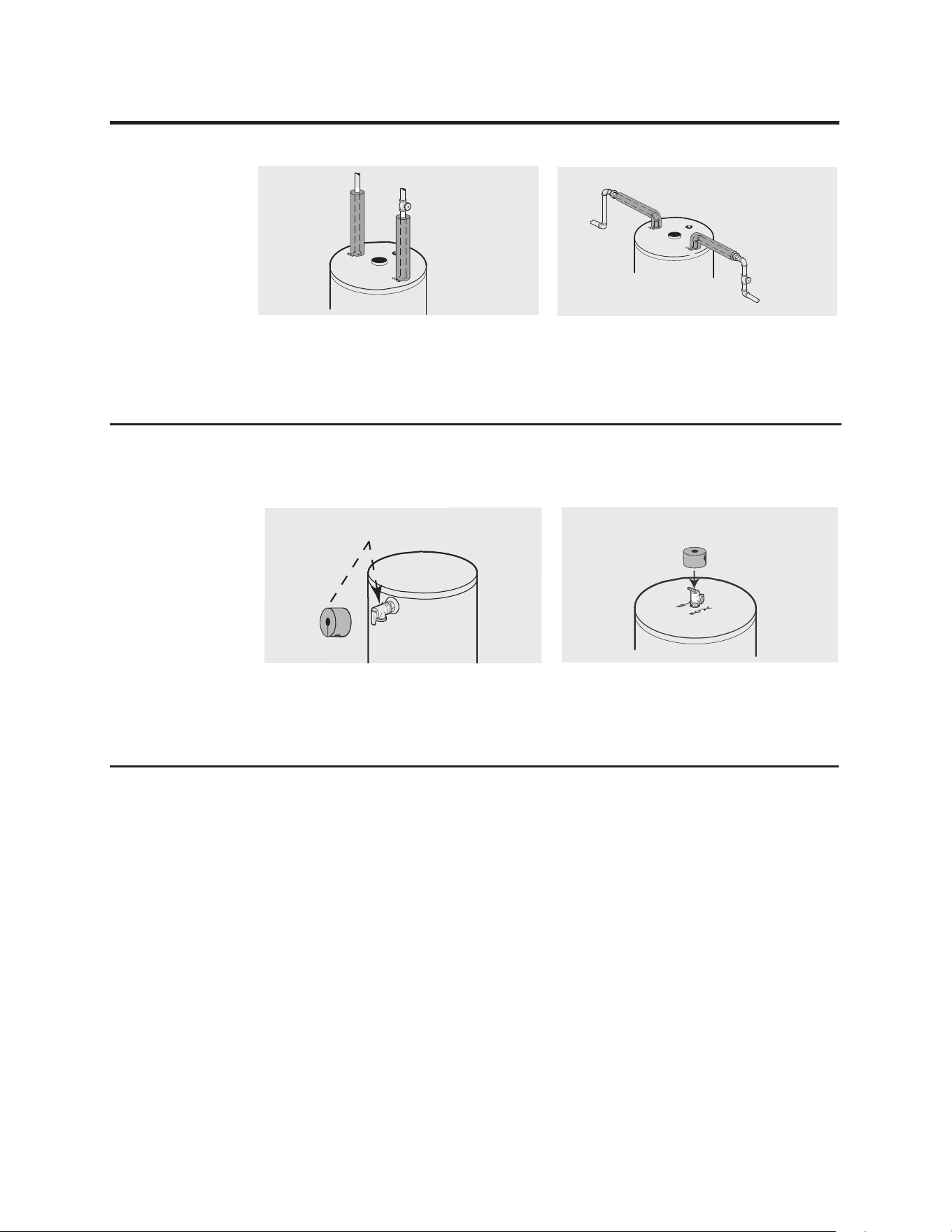
T&P Insulation Installation
Typical Side Connect T & P Arrangement.
Typical Top Connect T & P Arrangement.
Slip the insulation cover over the T&P
Valve through the center hole and align
the hole in the side with the opening of the
T&P Valve.
Ensure the T&P Valve opening is not
obstructed by the insulation.

18
Installation Checklist
A. Water Heater Location
B. Water Supply
C. Gas Supply
D. Relief Valve
E. Venting
❑ Close to outside wall.
❑ Indoors and protected from freezing
temperatures.
❑ Proper clearance from combustible surfaces
observed and water heater not installed on
carpeted floor.
❑ Sufficient fresh air supply for proper
operation of water heater.
❑ Air supply free of corrosive elements and
flammable vapors.
❑ Provisions made to protect area from water
damage.
❑ Sufficient room to service heater.
❑ Combustible materials, such as clothing, cleaning
materials, rags, etc. clear of the base of the heater.
❑ Water heater completely filled with water.
❑ Air purged from water heater and piping.
❑ Water connections tight and free of leaks.
❑ Gas line equipped with shut-off valve, union
and sediment trap.
❑ Approved pipe joint compound used.
❑ Soap and water solution used to check all
connections and fittings for possible gas leak.
❑ Gas Company inspected installation
(if required).
❑ Temperature and Pressure Relief Valve
properly installed and discharge line run to
open drain.
❑ Discharge line protected from freezing.
❑ Flue baffle properly hung in top of heater’s
flue.
❑ Air tube and vent tube properly installed.
❑ Vent terminal, air tube sealed with silicone bands
and sealants.
❑ Air tube securely fastened with screws.
19
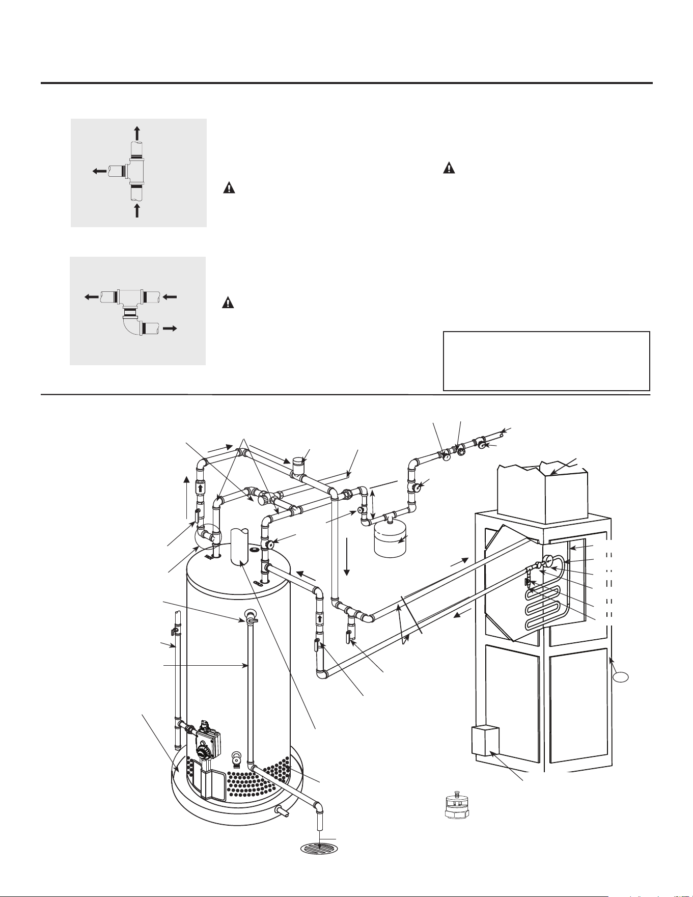
Tee fitting for vertical hot
water supply lines.
Hot water
supply to
house
From HOT
outlet on
water heater
Hot water
supply to
heating
unit
Supplemental instructions for gas water heaters installed in
potable/space heating applications
Local codes or plumbing authority requirements may vary from the instructions or diagrams provided in this
manual and take precedent over these instructions.
Tee fitting for horizontal hot
water supply lines.
From HOT
outlet on
water heater
Hot water
supply to
house
Hot water supply
to heating unit
Combination Potable and Space Heating Application
Tee fitting must be installed as shown. This
ensures that any air in the water lines will be
purged through the domestic water faucets
and showers.
DANGER: When this system requires
water for space heating at elevated
temperatures (above 125°F [52°C.]), a
mixing valve complying with the Standard
for Temperature Actuated Mixing Valves
for Hot Water Distribution Systems, ASSE
1017 must be installed in the hot water
supply line to the house in order to reduce
the scald hazard potential.
DANGER: Any piping or components
used in the installation of this water
heater in a combination potable and space
heating application must be suitable for
use with drinking water.
NOTICE: Suitable for (potable) water
heating and space heating applica-
tions. DO NOT use for space heating
application only
DANGER: If this water heater is in-
stalled in an application intended to supply
domestic hot water needs and hot water
for space heating purposes, do not connect
the heater to an existing heating unit or
components of a heating system that have
previously been used with a non drink-
ing water system. Toxic chemicals such
as those used for boiler treatment may be
present and will contaminate the drinking
water supply causing possible health risks.
Never introduce toxic chemicals, such as
those used for boiler treatment, into this
system.
NOTICE: 50' - 0" maximum
distance from water heater to fan
coil (developed length) is required
for Massachusetts State.
19
Typical Piping Diagram for Combination Potable/Space Heating Installation
Spring loaded check valve in heating
unit hot water supply line and cold water
return line (not supplied with water
heater)
NOTICE: This check valve is
incorporated in some heating units.
Refer to the installation instructions
supplied with specific heating unit to
determine if it is required.
All water piping shall be insulated
in accordance with Local and State
Energy Code.
Isolation valve in
cold water return
line from heating
unit (not supplied
with water heater)
Nominal 3/4" size mixing or tempering valve
(refer to warning above). Follow mixing or
tempering valve manufacturer’s instructions
for installation of the valve.
Temperature and pressure relief
valve discharge line
Air Handler
Drain valve
(not supplied with
water heater)
Hot water
to space heater
Temperature and Pressure Relief
Valve, tie to location approved by
local code
Isolation valve in hot water supply
line to heating unit (not supplied with
water heater)
3/4" cold water supply
3/4" Tempered domestic
hot water supply to house.
Gas line to water heater
6” Air Gap
Combustion Air Inlet
Openings
2 Gallon Thermal
Expansion Tank
(if required-not
supplied with water
heater)
Air vent
Heat Trap
6” Min.
3/4" Shut-Off Valve
(Typ.)
3/4" Check Valve with 1/8" Hole
Pressure Gauge
3/4" Shut-Off
Valve (Typ.)
3/4"
Shut-Off
Valve
(Typ.)
Piping loop between
water heater and fan
coil shall be flow guard
gold CPVC or equal
Hot water coil
All bronze pump.
Check valve
internal in pump.
Air bleed valve.
Water Sample Tap.
T
FAN
ON
OFF
HEAT
COOL
To HVAC
Unit.
Electronically controlled pump timer.
Activates every 6 hours for 60 seconds.
Wire to bronze pump.
3/4" HWS &
HWR to Heating
Coil.
Minimum of 2'-0" developed length
of 3/4" type "L" copper from the
water heater connection.
Water Heater drain pan installed
in accordance with the Local and
State Code
Water Heater to be in
accordance with the Local and
State Energy Code
Gas Fired
Water Heater
Gas Direct Vent
discharge must comply
with Local and State
Code
Vacuum Relief Valve
(Not Supplied)
If required, install per local codes
and valve manufacturer’s
instructions.
1
2
0
°
F
t
o
1
3
0
°
F
14
0°
F
See diagrams above for proper
pipe application for vertical or
horizontal supply lines
20
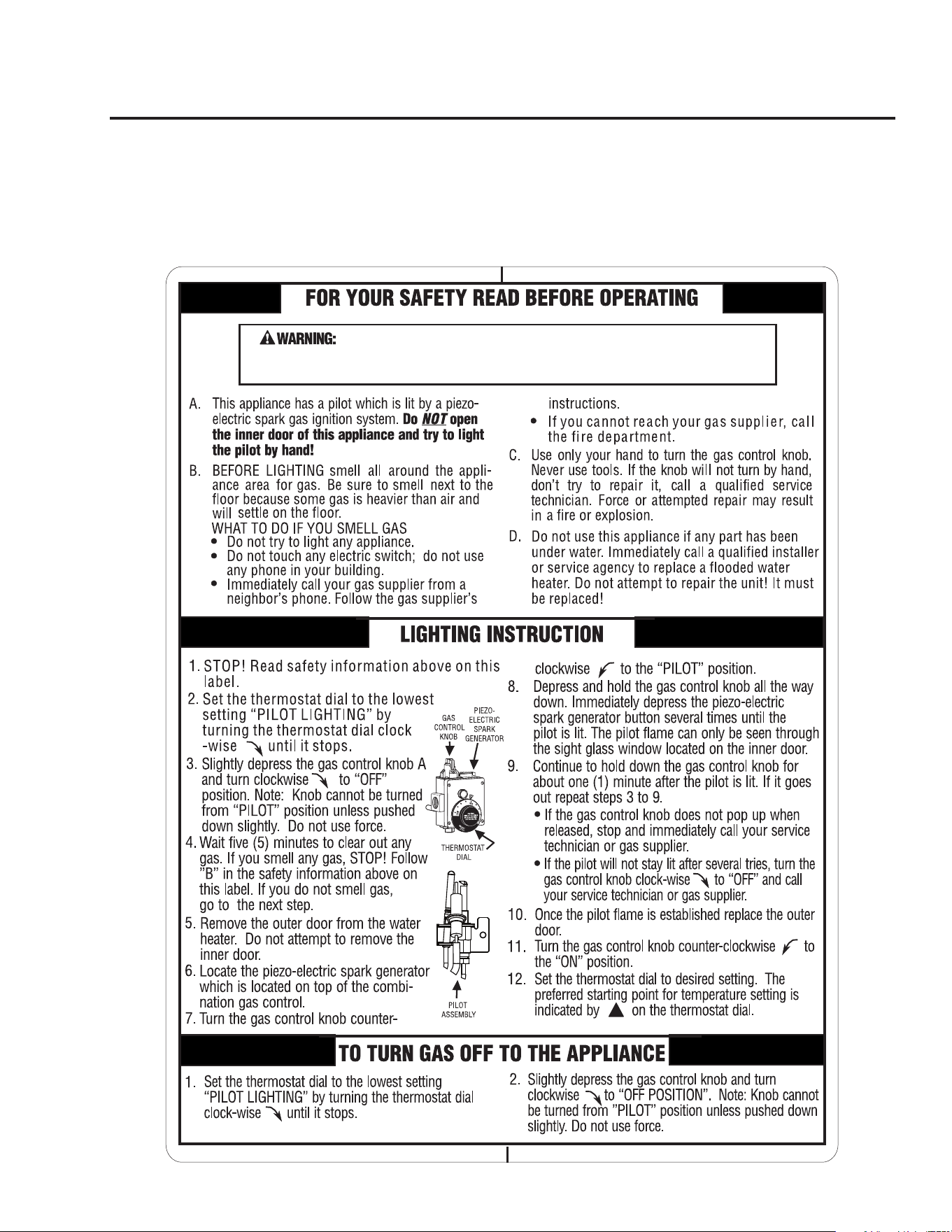
Lighting the water heater
Before operating this water heater, be sure to read and follow the instructions on the label pictured below
and all other labels on the water heater, as well as the warnings printed in this manual. Failure to do so
can result in unsafe operation of the water heater resulting in property damage, personal injury, or death.
Should you have any problems reading or following the instructions in this manual, STOP, and get help
from a qualified person.
instructions exactly, a re or explosion may result causing property damage,
personal injury or loss of life.
If you do not follow these instructions and the Use & Care Manual
21
Time/Temperature Relationship in Scalds
Water Temperature Time To Produce a Serious Burn
120°F (49°C) More than 5 minutes
125°F (52°C) 1
1
/2 to 2 minutes
130°F (54°C) About 30 seconds
135°F (57°C) About 10 seconds
140°F (60°C) Less than 5 seconds
145°F (63°C) Less than 3 seconds
150°F (66°C) About 1
1
/2 seconds
155°F (68°C) About 1 second
Table courtesy of Shriners Burn Institute
Safety Precautions
Do turn off manual gas shut-off valve if water
heater has been subjected to over heating, fire,
flood, physical damage or if the gas supply fails to
shut off.
DO NOT turn on water heater unless it is
completely filled with water.
DO NOT turn on water heater if cold water supply
shut-off valve is closed.
DO NOT allow combustible materials such as
newspaper, rags or mops to accumulate near water
heater.
DO NOT store or use gasoline or other flammable
vapors and liquids, such as adhesives or paint
thinner, in vicinity of this or any other appliance.
If such flammables must be used, open doors and
windows for ventilation, and all gas burning
appliances in the vicinity should be shut off
including their pilot burners, to avoid vapors
igniting.
NOTICE: Flammable vapors can be drawn by air
currents from surrounding areas to the water heater.
If there is any difficulty in understanding or
following the Operating Instructions or the Care
and Cleaning section, it is recommended that a
qualified person or serviceman perform the work.
CAUTION: Hydrogen gas can be produced in a hot water system served by this water heater that has not
been used for a long period of time (generally two weeks or more). HYDROGEN GAS IS EXTREMELY
FLAMMABLE!! To dissipate such gas and to reduce risk of injury, it is recommended that the hot water
faucet be opened for several minutes at the kitchen sink before using any electrical appliance connected to
the hot water system. If hydrogen is present, there will be an unusual sound such as air escaping through the
pipe as the water begins to flow. Do not smoke or use an open flame near the faucet at the time it is open.
!
DANGER: Hotter
water increases the
Potential for Hot Water
SCALDS. Households
with small children,
disabled, or elderly
persons may require a
120°F (49°C) or lower
gas control (thermostat)
setting to prevent
contact with HOT
water.
Water Temperature Setting
The temperature of the water in the water
heater can be regulated by setting the
temperature dial on the front of the gas
control (thermostat).
Safety and energy conservation are factors
to be considered when selecting the water
temperature setting of the water heater’s
gas control (thermostat(s)). The lower
the temperature setting, the greater the
savings in energy and operating costs.
To comply with safety regulations, the gas
control (thermostat) was set at its lowest
setting before the water heater was shipped
from the factory. The recommended
starting point temperature is 120°F
(49°C).
Water temperatures above 125°F (52° C)
can cause severe burns or death from
scalding. Be sure to read and follow the
warnings outlined in this manual and on
the label located on the water heater near
the gas control (thermostat).
Mixing valves are recommended for
reducing point of use water temperature
by mixing hot and cold water in branch
water lines. It is recommended that a
mixing valve complying with the Standard
for Temperature Actuated Mixing Valves
for Hot Water Distribution Systems, ASSE
1017 be installed. See page 4 for more
details and contact a licensed plumber or
the local plumbing authority for further
information.
The chart below may be used as a
guide in determining the proper water
temperature for your home.
22
Water Temperature Setting…
Maximum water temperatures occur just after
the burner has shut off. To determine the water
temperature, turn on a hot water faucet and
place a thermometer in the water stream.
The reference mark p on the rim of the
temperature dial, represents an approximate
water temperature of
120°F (49°C).
The reference mark
A
represents an
approximate water temperature of
130°F (54°C).
Each reference mark above or below these
points indicates an approximate change of
10°F (5.5°C).
To adjust the temperature, turn the
temperature dial to an initial setting of
120°F (49°C).
A condition known as “stacking” or “layering”
can occur when a series of short and frequent
hot water draws are taken.
The hottest temperature water will be at the top
of the tank, closest to the outlet pipe delivering
hot water to the home.
Stacking can cause this top layer of water to
be hotter than the water toward the bottom
of the tank near the gas control (thermostat).
Therefore, always remember to test the water
temperature with your hand before use and
remember that hotter water increases the risk
of scald injury.
Also, always supervise young children or
others who are incapacitated.
The gas control (thermostat) is constructed
with a built in safety shut-off device designed
to shut off the gas supply to the burner if the
pilot flame is extinguished for any reason.
The gas control (thermostat) is also equipped
with a single use gas shut off device that
will shut off the gas supply to the burner if
the water heater exceeds normal operating
temperatures. Refer to the (Before You Call
For Service) section of this manual, or contact
your dealer.
WARNING: Should overheating occur or
the gas supply fail to shut off, turn off the
manual gas control valve to the appliance.
If the water heater has been subjected to fire,
flood or physical damage, turn off power to
water heater, and do not operate the water
heater again until it has been checked by a
qualified service technician.
NOTICE: DO NOT use this appliance if
any part has been under water. Immediately
call a qualified installer or service agency
to replace a flooded water heater. DO NOT
attempt to repair the unit! It must be
replaced.
!
100°F
(38°C)
90°F
(32°C)
80°F
(27°C)
110°F
(43°C)
120°F
(49°C)
130°F
(54°C)
140°F
(60°C)
150°F
(66°C)
160°F
(71°C)
Temperatures are approximate
Operating the water heater
23
Care and cleaning of the water heater
Draining the Water Heater
!
CAUTION: Shut off gas to the
water heater at the gas control
(thermostat) gas cock or manual
shut-off valve before draining
water.
!
DANGER: Before manually
operating the temperature and
pressure relief valve, make certain
no one will be exposed to the hot
water released by the valve. The
water drained from the tank may be
hot enough to present a scald
hazard and should be directed to a
suitable drain to prevent injury or
damage.
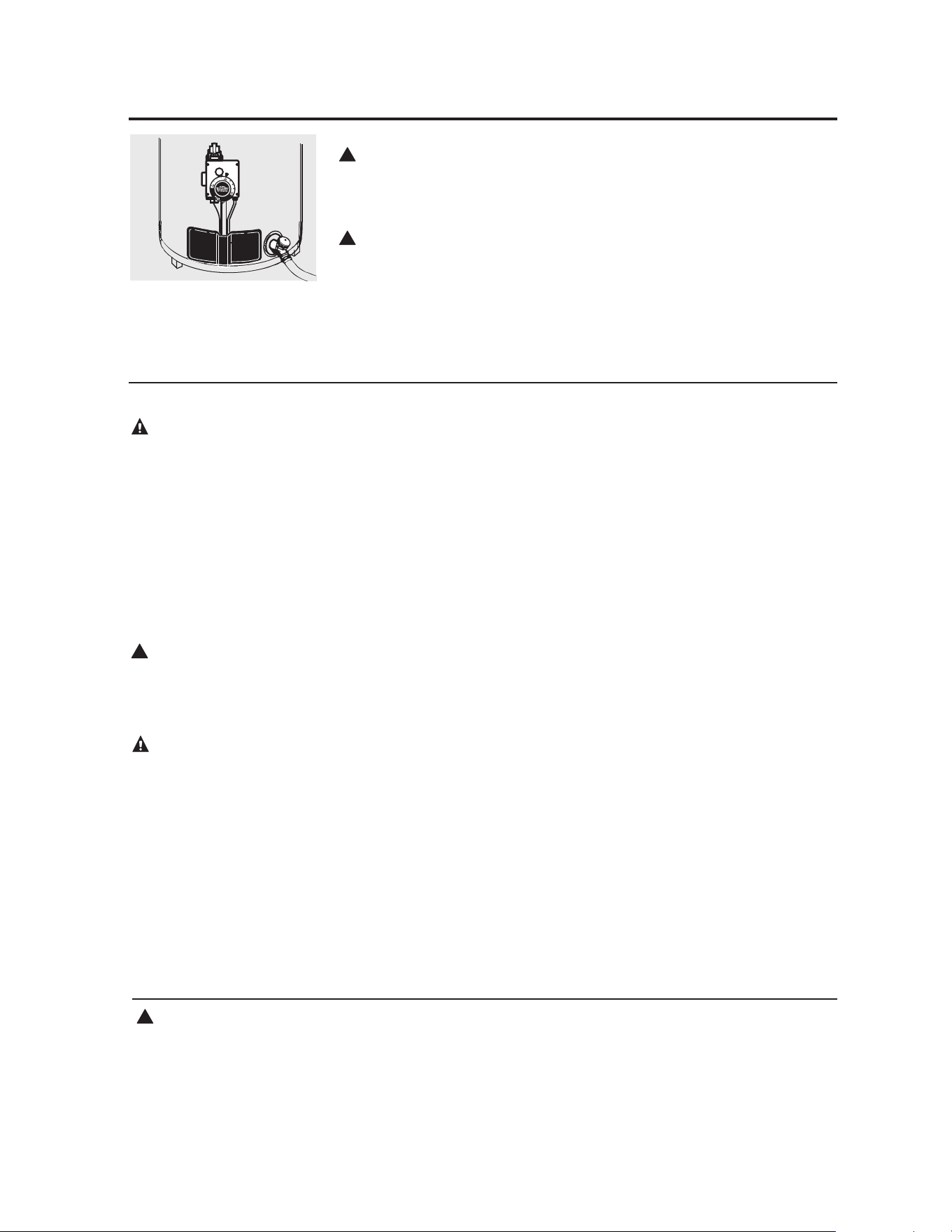
In order to drain the water heater, turn
off the cold water supply. Open a hot
water faucet or lift the handle on the
relief valve to admit air to the tank.
Attach a garden hose to the drain
valve on the water heater and direct
the stream of water to a drain. Open
the valve.
Housekeeping
Vacuum around the base of the water
heater for dust, dirt and lint on a
regular basis. Visually inspect pilot
burner and relight if necessary.
To ensure sufficient ventilation
and combustion air supply, proper
clearances must be maintained.
When installed in a closet, DO
NOT block or obstruct any of
the combustion air inlet openings
located around the perimeter of
the water heater. A minimum of 1”
(2.5 cm) is required between these
combustion air inlet openings and
any obstruction.
Routine Preventative Maintenance
Properly maintained, your water heater
will provide years of dependable
trouble-free service.
It is recommended that a periodic
inspection of the gas control
(thermostat), burner, relief valve,
internal flue-way and venting system
should be made by service personnel
qualified in gas appliance repair.
It is suggested that a routine
preventative maintenance program be
established and followed by the user.
At least once a year, lift and release
the lever handle on the temperature
pressure relief valve, located near the
top of the water heater, to make certain
the valve operates freely. Allow several
gallons to flush through the discharge
line to an open drain.
NOTICE: If the temperature and
pressure relief valve on the hot water
heater discharges periodically, this
may be due to thermal expansion in
a closed water system. Contact the
water supplier or your plumbing
contractor on how to correct this. DO
NOT plug the relief valve outlet.
A water heater’s tank can act as a
settling basin for solids suspended
in the water. It is therefore not
uncommon for hard water deposits to
accumulate in the bottom of the tank.
If allowed to accumulate, these solids
can cover the gas control (thermostat)
sensors, causing the sensors to operate
erratically. Because accumulated solids
can prevent the gas control (thermostat)
sensors from accurately reading the
water temperature, the water at the
fixture can be hotter than the gas
control (thermostat) dial setting. It is
suggested that a few quarts (litres)
of water be drained from the water
heater’s tank every month to clean the
tank of these deposits.
Rapid closing of faucets or solenoid
valves in automatic water using
appliances can cause a banging noise
heard in a water pipe. Strategically
located risers in the water pipe system
or water hammer arresting devices can
be used to minimize the problem.
The anode rod should be inspected and
replaced when more than 6” (15.2 cm)
of core wire is exposed at either end of
the rod.
Make sure the cold water supply is
turned off before replacing the anode
rod.
DANGER: Before
manually operating the
relief valve, make certain
no one will be exposed to
the danger of the hot
water released by the
valve. The water may be
hot enough to create a
scald hazard. The water
should be released into a
suitable drain to prevent
injury or property damage.
!
DANGER: Combustible
materials, such as clothing,
cleaning materials, or
flammable liquids, etc., must
not be placed against or next
to the water heater.
DANGER: Failure to
perform the
recommended Routine
Preventative Maintenance
can harm the proper
operation of this water
heater, which can cause
carbon monoxide
dangers, excessive hot
water temperatures and
other potentially
hazardous conditions.
!
DANGER: Hotter
water increases the
potential for Hot Water
Scalds.
24
Venting System Inspection
It is recommended that the water heater’s
internal flue, vent, and air pipes be inspected
annually to be certain it is clean.
Inspect the gas venting system and the
termination cap.
Make certain the vent system, vent, and air
pipes is properly sealed and securely attached.
If after inspection of the vent system you
found soot or deterioration; call the local gas
utility to correct the problem and clean the
flue, and venting system or replace the flue
baffle, before resuming operation of the water
heater.
Burner Inspection
Visually inspect the pilot and main burners
annually.
Through the sight glass, inspect the pilot
burner flame with the main burner off and
inspect the main burner while firing.
If any unusual burner operation is noted, the
water heater should be shut off until qualified
service assistance can be obtained.
!
CAUTION: For your safety, cleaning of
the burner must be performed only by
qualified service personnel. The burner
chamber is a sealed area. If the burner
access door is removed, the burner access
door gasket must be replaced.
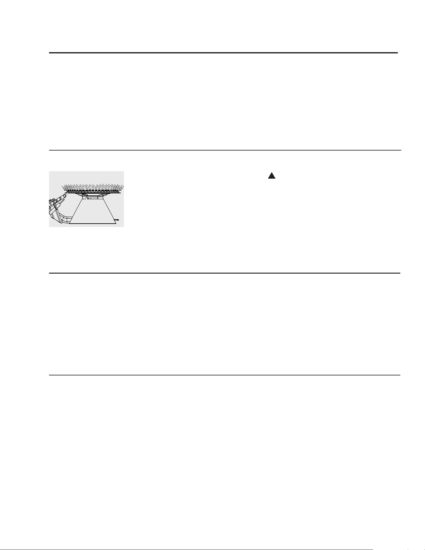
For cleaning, remove the burner from the
water heater. A vacuum cleaner can be used
on the burner and floor shield inside the water
heater. The burner can also be cleaned by
scrubbing with mild detergent.
Proper burner and pilot
burner pattern.
Vacation and Extended Shut-Down
If the water heater is to remain idle for an
extended period of time, the power and
water to the appliance should be turned off
to conserve energy and prevent a build-up of
dangerous hydrogen gas.
The water heater and piping should be
drained if they might be subjected to freezing
temperatures.
After a long shut-down period, the water
heater’s operation and controls should be
checked by qualified service personnel.
Make certain the water heater is completely
filled again before placing it in operation.
NOTICE: Refer to the
Hydrogen Gas Caution in
the Operating Instructions.
Anode Rod
This water heater is equipped with an anode
rod designed to prolong the life of the glass
lined tank. The anode rod is slowly consumed,
thereby eliminating or minimizing corrosion
of the glass lined tank.
Water sometimes contains a high sulfate and/
or mineral content and together with cathodic
protection process can produce a hydrogen
sulfide, or rotten egg odor in the heated water.
Chlorination of the water supply should
minimize the problem.
NOTICE: DO NOT
remove the anode rod
from the water heater’s
tank, except for inspection
and/or replacement, as
operation with the anode
rod removed will greatly
shorten the life of the glass
lined tank and will exclude
warranty coverage.
Care and cleaning of the water heater
25
Problem Possible Causes What To Do
Condensation This usually happens when This is normal. After the water in the tank warms
a new water heater is up, the condensation will disappear. If, however, the
filled for the first time. condition persists, examine the piping and fittings
for possible leaks.
Moisture from the products This is normal and will disappear in time. Excessive
of combustion condensing condensation can cause pilot burner outage.
on the tank surface.
An undersized water Use a water heater size that meets the requirements
heater will cause of your needs.
condensation. Contact a qualified service technician for service.
Yellow flame Scale on top of the burner. Contact a qualified service technician to remove scale.
or soot
Flue or Combustion air inlet Remove obstruction or debris from flue or
openings are restricted. combustion air inlet openings on water heater jacket.
Not enough combustion or Proper operation of the water heater requires air for
ventilation air supplied to combustion and ventilation. See the Combustion and
the water heater location. Ventilation Air information in the “Installing The
Water Heater” section of this manual.
Unable to light Air in gas line. Contact a qualified service technician to purge the air
the pilot burner from the gas line.
Pilot burner orifice clogged. The pilot burner should be cleaned or replaced by a
qualified service technician.
Pilot burner tube pinched or The pilot burner should be cleaned, repaired or
clogged. replaced by a qualified service technician.
Gas cock knob not See the “Lighting The Water Heater” section of this
correctly positioned. manual.
Pilot burner does not stay Loose thermocouple. The connection at the gas control (thermostat) should
lit when the RED be tightened by a qualified service technician.
button is released
Thermocouple defective. The thermocouple should be replaced by a qualified
service technician.
Safety magnet defective. The gas control (thermostat) should be replaced by a
qualified service technician.
Gas Control’s (Thermostat’s) The gas control (thermostat) should be replaced by a
single use gas shut-off device qualified service technician.
has opened.
Improper vent assembly Contact a qualified service technician for service.
and installation.
CAUTION: For your safety DO NOT attempt repair of gas piping, gas control (thermostat), burners, vent connectors or
other safety devices. Refer repairs to qualified service personnel.
Before You Call For Service
Troubleshooting Tips
Save time and money! Review the charts on the following pages first and you may not need to call for service.
26
Problem Possible Causes What To Do
Rumbling noise Scale and sediment Clean tank.
in tank.
Relief valve Pressure build up This is an unacceptable condition and must be
producing popping caused by thermal corrected. Contact the water supplier or plumbing
noise or draining expansion to a contractor on how to correct this. Do not plug the
closed system. relief valve outlet.
Not enough or Water usage may have Wait for the water heater to recover after an
no hot water exceeded the capacity abnormal demand.
of the water heater.
Low gas pressure. Check gas supply pressure and manifold pressure.
The pilot burner may be out. Check the pilot burner. If necessary, relight using the
instructions in the “Lighting The Water Heater”
section of this manual.
The gas control (thermostat) See the “Water Temperature Setting” of The Water
may be set too low. Heater section of this manual.
Leaking or open hot Make sure all faucets are closed.
water faucets.
Cold water inlet ● This is normal. The colder inlet water takes longer
temperature may be to heat.
colder during the winter months.
Water is too hot The gas control (thermostat) ● See the “Water Temperature Setting” of The Water
is set too high. Heater section of this manual.
Gas Control (Thermostat) ● Contact a qualified service technician to replace the
Defective. gas control (thermostat).
CAUTION: For your safety DO NOT attempt repair of gas piping, gas control (thermostat), burners, vent connectors or
other safety devices. Refer repairs to qualified service personnel.
Troubleshooting Tips
Save time and money! Review the charts on the following pages first and you may not need to call for service.
Before You Call For Service
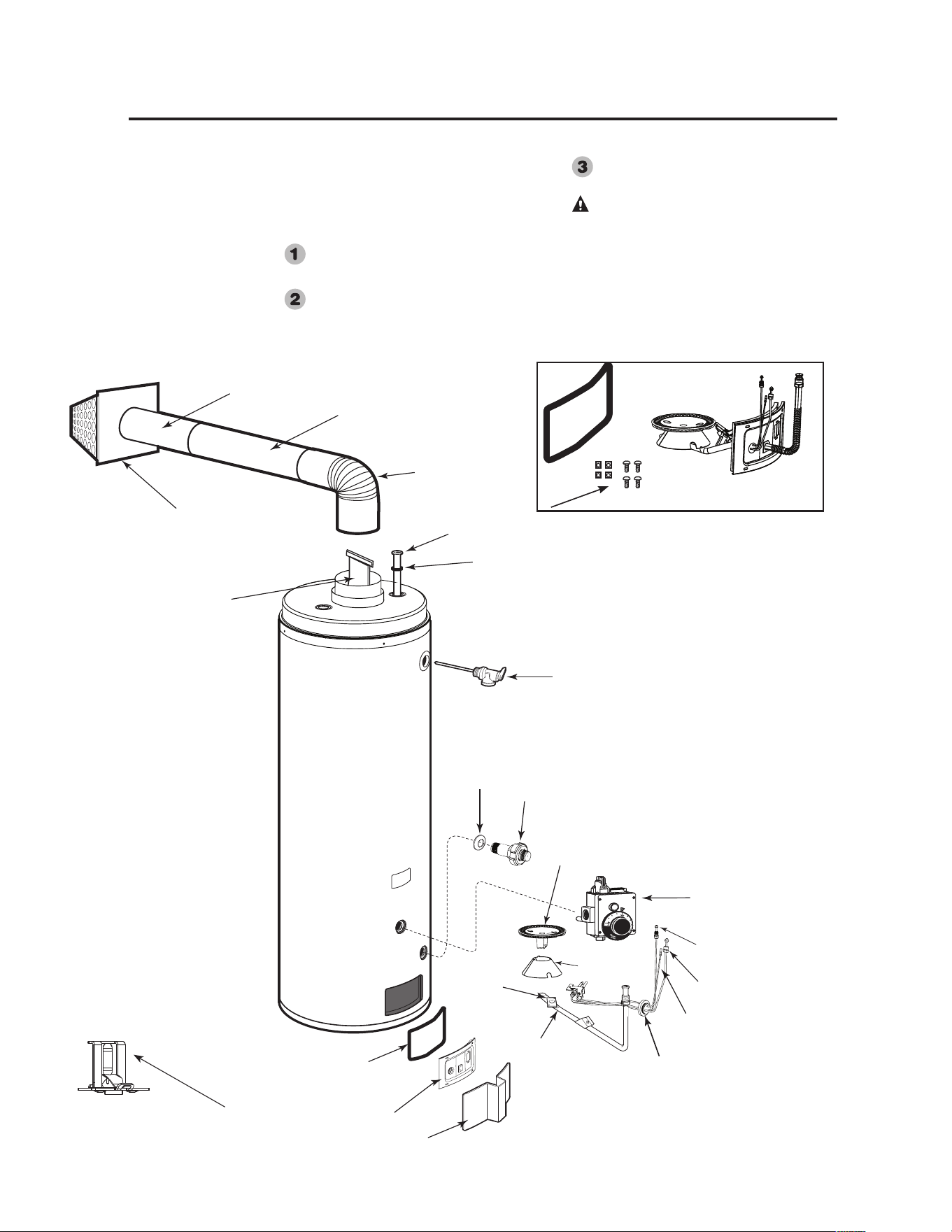
27
Replacement Parts
Instructions For Placing a Parts Order
Address parts orders to the distributor
or store from where the heater was
purchased.
All parts orders should include:
The model and serial number of the
water heater from the rating plate.
Specify type of gas (natural or LP) as
marked on the rating plate.
Part description (as noted below) and
number of parts desired.
CAUTION: For your safety, DO
NOT attempt repair of gas piping, gas
control (thermostat), burners, vent
connectors or other safety devices.
Refer repairs to qualified service
personnel.
Vent
Terminal Cap
T&P Relief Valve
Drain Valve
Shroud
Drain Valve
Inner Door
Jacket Door
Burner
Gas Control
(thermostat)
Pilot Supply
Tube
Piezo
Ignitor Wire
Thermocouple
Burner Supply
Tube
Burner
Orifice
Dip Tube
Dip Tube
Gasket
Flue Baffle
and
Hanger
Main Air Tube
Sliding Air Tube
Air Tube Elbow
Inner Door
Gasket
Burner
Cone
Grommet
Burner Assembly Kit
The kit provides extra speed clips and
tamper resistant screws.
*Combustion Shut-off Device (enlarged view)
Located inside the combustion chamber.

28
IF YOU NEED SERVICE
1. Should you have any questions about your new water
heater, or if it requires adjustment, repair, or routine
maintenance, it is suggested that you first contact your
installer, plumbing contractor or previously agreed upon
service agency. In the event the firm has moved, or is
unavailable, refer to the telephone directory, commercial
listings or local utility for qualified service assistance.
2. Should your problem not be solved to your complete
satisfaction, you should then contact the Manufacturer’s
National Service Department at the following address:
In the United States:
1241 Carwood Court
Montgomery, Alabama 36117
Phone: 1-866-279-4566.
When contacting the manufacturer, the following
information will be requested:
a. Model and serial number of the water heater as shown on
the rating plate attached to the jacket of the heater.
b. Address where the water heater is located and physical
location.
c. Name and address of installer and any service agency who
performed service on the water heater.
d. Date of original installation and dates any service work
was performed.
e. Details of the problems as you can best describe them.
f. List of people, with dates, who have been contacted
regarding your problem.
The Commonwealth of Massachusetts requires compliance with 5.08:
Modications to NFPA-54, Chapter 10 regulation 248 CMR 4.00 and
5.00 for installation of through – the – wall vented gas appliances as
follows:
(a) For all side wall horizontally vented gas fueled equipment installed in
every dwelling, building or structure used in whole or in part for residen-
tial purposes, including those owned or operated by the Commonwealth
and where the side wall exhaust vent termination is less than seven (7)
feet above nished grade in the area of the venting, including but not lim-
ited to decks and porches, the following requirements shall be satised:
1. INSTALLATION OF CARBON MONOXIDE DETECTORS. At the
time of installation of the side wall horizontal vented gas fueled equip-
ment, the installing plumber or gastter shall observe that a hard wired
carbon monoxide detector with an alarm and battery back-up is installed
on the oor level where the gas equipment is to be installed. In addition,
the installing plumber or gastter shall observe that a battery operated or
hard wired carbon monoxide detector with an alarm is installed on each
additional level of the dwelling, building or structure served by the side
wall horizontal vented gas fueled equipment. It shall be the responsibility
of the property owner to secure the services of qualied licensed profes-
sionals for the installation of hard wired carbon monoxide detectors
a. In the event that the side wall horizontally vented gas fueled equip-
ment is installed in a crawl space or an attic, the hard wired carbon
monoxide detector with alarm and battery back-up may be installed on
the next adjacent oor level.
b. In the event that the requirements of this subdivision can not be met
at the time of completion of installation, the owner shall have a period of
thirty (30) days to comply with the above requirements; provided, how-
ever, that during said thirty (30) day period, a battery operated carbon
monoxide detector with an alarm shall be installed.
2. APPROVED CARBON MONOXIDE DETECTORS. Each carbon
monoxide detector as required in accordance with the above provisions
shall comply with NFPA 720 and be ANSI/UL 2034 listed and IAS certi-
ed.
3. SIGNAGE. A metal or plastic identication plate shall be permanently
mounted to the exterior of the building at a minimum height of eight (8)
feet above grade directly in line with the exhaust vent terminal for the
horizontally vented gas fueled heating appliance or equipment. The sign
shall read, in print size no less than one-half (1/2) inch in size, “GAS
VENT DIRECTLY BELOW. KEEP CLEAR OF ALL OBSTRUC-
TIONS”.
4. INSPECTION. The state or local gas inspector of the side wall hori-
zontally vented gas fueled equipment shall not approve the installation
unless, upon inspection, the inspector observes carbon monoxide detec-
tors and signage installed in accordance with the provisions of 248 CMR
5.08(2)(a)1 through 4.
(b) EXEMPTIONS: The following equipment is exempt from 248 CMR
5.08(2)(a)1 through 4:
1. The equipment listed in Chapter 10 entitled “Equipment Not Required
To Be Vented” in the most current edition of NFPA 54 as adopted by the
Board; and
2. Product Approved side wall horizontally vented gas fueled equipment
installed in a room or structure separate from the dwelling, building or
structure used in whole or in part for residential purposes.
(c) MANUFACTURER REQUIREMENTS - GAS EQUIPMENT
VENTING SYSTEM PROVIDED. When the manufacturer of Product
Approved side wall horizontally vented gas equipment provides a vent-
ing system design or venting system components with the equipment, the
instructions provided by the manufacturer for installation of the equip-
ment and the venting system shall include:
1. Detailed instructions for the installation of the venting system design
or the venting system components; and
2. A complete parts list for the venting system design or venting system.
(d) MANUFACTURER REQUIREMENTS - GAS EQUIPMENT
VENTING SYSTEM NOT PROVIDED. When the manufacturer of a
Product Approved side wall horizontally vented gas fueled equipment
does not provide the parts for venting the ue gases, but identies “spe-
cial venting systems”, the following requirements shall be satised by the
manufacturer:
1. The referenced “special venting system” instructions shall be included
with the appliance or equipment installation instructions; and
2. The “special venting systems” shall be Product Approved by the
Board, and the instructions for that system shall include a parts list and
detailed installation instructions.
(e) A copy of all installation instructions for all Product Approved side
wall horizontally vented gas fueled equipment, all venting instructions,
all parts lists for venting instructions, and/or all venting design instruc-
tions shall remain with the appliance or equipment at the completion of
the installation.
(3) After NFPA-54 section 10.10.4.2 add a new section 10.10.4.3 as fol-
lows:
When more than four gas appliances are to be vented through a common
gas vent or common horizontal vent manifold, a plan of the proposed
vent installation shall be submitted to the Inspector and the serving gas
supplier for review and approval.
Important Instructions for the Commonwealth of Massachusetts