
Loading ...
Loading ...
MicroSub+ / PowerWedge+ with DCD™ Amplifier Technology 3
POWER CONNECTIONS PLUG
To connect the power wires and remote
turn-on wire to the amplifier, unplug the
“Power Connections” plug from the amplifier
panel (pull back firmly) and back out the set
screws on the connector plug using a Phillips
head screwdriver. Strip 3/8 inch (10 mm) of
insulation from the end of each wire and insert
the bare wire into the receptacle on the power
connector plug, seating it firmly so that no
bare wire is exposed. While holding each wire
in place, tighten each set screw firmly, taking
care not to strip the head of the screw.
Warning! Never make power connections with
a “live” wire. Always disconnect the negative
battery post before making any connections or
adjustments to a 12V power connection! Failure
to make safe, tight, high-integrity connections
can result in fire and extensive damage!
inputs of the amplifier. The amplifier’s
input section automatically sums stereo
signals to mono for the internal amplifier
section. When feeding a single, low-level
RCA input connection, use a Y-adaptor
splitter to split the mono signal and connect
it to both Left and Right RCA inputs.
7. Signal Input (High-Level): If your system
does not offer a preamp level signal option,
you can connect speaker level signals directly
to the “High-Level Inputs” connector using
the supplied 4-pin plug and wire harness.
Simply splice the appropriate left/right
and positive/negative wires to the included
harness, and plug the harness into the “High-
Level Inputs” connector on the amplifier. The
amplifier will attenuate the high-level signal
to make it compatible with its input stage.
Refer to the table below for corresponding
wire color information. Make sure to observe
correct polarity in making high-level input
connections. Failure to do so will result
in a loss of signal (poor performance).
8. Make necessary adjustments to the
input sensitivity and filter controls.
9. With the optional RBC-1 Remote Level
Control (sold separately), you can control
the amplifier’s output level from the
front of the vehicle. Connect the RBC-1
to the amplifier’s panel-mounted RJ11
input jack. (Refer to Appendix B)
50
80
125100
200
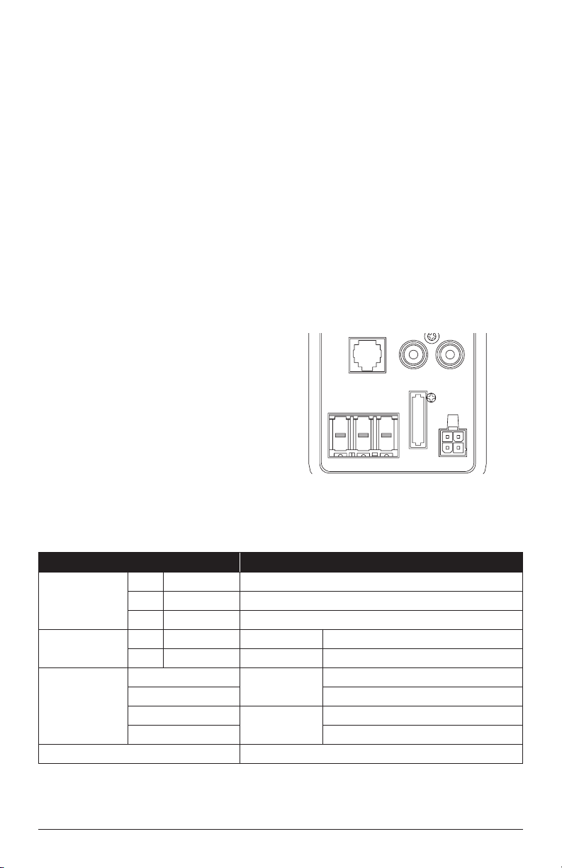
Low-Pass
Filter Freq. (Hz)
Turn-On
Mode
Remote
Level
Control
Low-Level Inputs
High-Level
Inputs
FUSE
(30A)
(
L
) (
R
)
Input
Sensitivity
Min. Max.
Signal
|
DC
|
Rem 0
|
180 deg.
+12 VDC GND Remote
Output
Polarity
Power Connections
Power
(green)
Protect
(red)
Connection Description
Power
Connections
+ +12 VDC Positive (+12V) Power Connection
– GND Negative (GND) Ground Connection
R Remote Positive (+12V) Remote Turn-On Input
Low-Level Inputs
(RCA Jacks)
(L) White RCA Ch. 1 Input Left Channel Signal Input
(R) Red RCA Ch. 2 Input Right Channel Signal Input
High-Level Inputs
(4-Pin
Connector)
White
Ch. 1 Input
(+) Left Channel Positive
White/Black (–) Left Channel Negative
Gray
Ch. 2 Input
(+) Right Channel Positive
Gray/Black (–) Right Channel Negative
Remote Level Control RJ11 Input Jack for RBC-1 (sold separately)
Loading ...
Loading ...
Loading ...