System
www.lg.com
Please read this installation manual completely before installing the product.
Installation work must be performed in accordance with the national wiring
standards by authorized personnel only.
Please retain this installation manual for future reference after reading it
thoroughly.
INSTALLATION MANUAL
AIR
CONDITIONER
P/NO : MFL46912318
Copyright © 2010 - 2018 LG Electronics Inc. All Rights Reserved.
ENGLISH
FRANCAIS
ESPAÑOL
2 Outside Unit
CAUTION
: Improper installation, adjustment, alteration, service or maintenance can void the warranty.
The weight of the condensing unit requires caution and proper handling procedures when lifting
or moving to avoid personal injury. Use care to avoid contact with sharp or pointed edges.
Safety Precautions
• Always wear safety eye wear and work gloves when installing equipment.
• Never assume electrical power is disconnected. Check with meter and equipment.
• Keep hands out of fan areas when power is connected to equipment.
• R-410A causes frostbite burns.
• R-410A is toxic when burned.
NOTE TO INSTALLING DEALER: The Owners Instructions and Warranty are to be given to the owner
or prominently displayed near the indoor Furnace/Air Handler Unit.
When wiring:
Electrical shock can cause severe personal injury or death. Only a qualified,
experienced electrician should attempt to wire this system.
• Do not supply power to the unit until all wiring and tubing are completed or reconnected and checked.
• Highly dangerous electrical voltages are used in this system. Carefully refer to the wiring diagram and these
instructions when wiring. Improper connections and inadequate grounding can cause accidental injury or death.
• Ground the unit following local electrical codes.
• Connect all wiring tightly. Loose wiring may cause overheating at connection points and a possible fire hazard.
When transporting:
Be careful when picking up and moving the indoor and outdoor units. Get a partner to help, and
bend your knees when lifting to reduce strain on your back. Sharp edges or thin aluminum fins on
the air conditioner can cut your finger.
When installing...
... in a wall: Make sure the wall is strong enough to hold the unit's weight.
It may be necessary to construct a strong wood or metal frame to provide added support.
... in a room: Properly insulate any tubing run inside a room to prevent "sweating" that can cause
dripping and water damage to wall and floors.
... in moist or uneven locatinons: Use a raised concrete pad or concrete blocks provide a solid,
level foundation for the outdoor unit. This prevents water damage and abnormal vibration.
... in an area with high winds: Securely anchor the outdoor unit down with bolts and a metal
frame. Provide a suitable air baffle.
... in a snowy area(for Heat Pump Model): Install the outdoor unit on a raised platform that is
higher than drifting snow. Provide snow vents.
When connecting refrigerant tubing
• Keep all tubing runs as short as possible.
• Use the flare method for connecting tubing.
• Check carefully for leaks before starting the test run.
When servicing
• Turn the power OFF at the main power box(mains) before opening the unit to check or repair
electrical parts and wiring.
• Keep your fingers and clothing away from any moving parts.
• Clean up the site after you finish, remembering to check that no metal scraps or bits of wiring have
been left inside the unit being serviced.
Special warnings
WARNING
• Installation or repairs made by unqualified persons can result in hazards to you and others.
Installation MUST conform with local building codes or, in the absence of local codes, with the National Electrical
Code NFPA 70/ANSI C1-1993 or current edition and Canadian Electrical Code Part1 CSA C.22.1.
• The information contained in the manual is intended for use by a qualified service technician familiar with safety
procedures and equipped with the proper tools and test instruments.
• Failure to carefully read and follow all instructions in this manual can result in equipment malfunction, property
damage, personal injury and/or death.
IMPORTANT!
Please read this instruction sheet completely before installing the product.
This air conditioning system meets strict safety and operating standards. As the installer or service
person,it is an important part of your job to install or service the system so it operates safely and
efficiently.

ARUN Series Outdoor Unit Installation Manual
TABLE OF CONTENTS
ENGLISH
Installation Manual 3
Safety Precautions......................................................................................................4
Installation Process....................................................................................................8
Outdoor Units Information.........................................................................................9
Before installation.....................................................................................................10
Select the Best Location ..........................................................................................11
Installation Space .....................................................................................................12
Installation.................................................................................................................16
Refrigerant piping.....................................................................................................19
Electrical Wiring........................................................................................................38
Test Run.....................................................................................................................53
Caution For Refrigerant Leak ..................................................................................63
Installation guide at the seaside..............................................................................65
Safety Precautions
4 Outside Unit
Safety Precautions
To prevent injury to the user or other people and property damage, the following instructions must
be followed.
n Incorrect operation due to ignoring instruction will cause harm or damage. The seriousness is
classified by the following indications.
n Meanings of symbols used in this manual are as shown below.
This symbol indicates the possibility of death or serious injury.
This symbol indicates the possibility of injury or damage to properties only.
Be sure not to do.
Be sure to follow the instruction.
Installation
• Have all electric work done by a licensed electrician according to "Electric Facility
Engineering Standard" and "Interior Wire Regulations" and the instructions given in this
manual and always use a special circuit.
- If the power source capacity is inadequate or electric work is performed improperly,
electric shock or fire may result.
• Ask the dealer or an authorized technician to install the air conditioner.
- Improper installation by the user may result in water leakage, electric shock, or fire.
• Always ground the product.
- There is risk of fire or electric shock.
• Always intstall a dedicated circuit and breaker.
- Improper wiring or installation may cause fire or electric shock.
• For re-installation of the installed product, always contact a dealer or an Authorized Service
Center.
- There is risk of fire, electric shock, explosion, or injury.
• Do not install, remove, or re-install the unit by yourself (customer).
- There is risk of fire, electric shock, explosion, or injury.
• Do not store or use flammable gas or combustibles near the air conditioner.
- There is risk of fire or failure of product.
• Use the correctly rated breaker or fuse.
- There is risk of fire or electric shock.
• Prepare for strong wind or earthquake and install the unit at the specified place.
- Improper installation may cause the unit to topple and result in injury.
• Do not install the product on a defective installation stand.
- It may cause injury, accident, or damage to the product.

Safety Precautions
ENGLISH
Installation Manual 5
• When installing and moving the air conditioner to another site, do not charge it with a
different refrigerant from the refrigerant specified on the unit.
- If a different refrigerant or air is mixed with the original refrigerant, the refrigerant cycle
may malfunction and the unit may be damaged.
• Do not reconstruct to change the settings of the protection devices.
- If the pressure switch, thermal switch, or other protection device is shorted and operated
forcibly, or parts other than those specified by LGE are used, fire or explosion may result.
• Ventilate before operating air conditioner when gas leaked out.
- It may cause explosion, fire, and burn.
• Securely install the cover of control box and the panel.
- If the cover and panel are not installed securely, dust or water may enter the outdoor unit
and fire or electric shock may result.
• If the air conditioner is installed in a small room, measures must be taken to prevent the
refrigerant concentration from exceeding the safety limit when the refrigerant leaks.
- Consult the dealer regarding the appropriate measures to prevent the safety limit from
being exceeded. Should the refrigerant leak and cause the safety limit to be exceeded,
harzards due to lack of oxygen in the room could result.
• Use a vacuum pump or Inert (nitrogen) gas when doing leakage test or air purge. Do not
compress air or Oxygen and do not use Flammable gases. Otherwise, it may cause fire or
explosion.
- There is the risk of death, injury, fire or explosion.
Operation
• Do not damage or use an unspecified power cord.
- There is risk of fire, electric shock, explosion, or injury.
• Use a dedicated outlet for this appliance.
- There is risk of fire or electrical shock.
• Be cautious that water could not enter the product.
- There is risk of fire, electric shock, or product damage.
• Do not touch the power switch with wet hands.
- There is risk of fire, electric shock, explosion, or injury.
• When the product is soaked (flooded or submerged), contact an Authorized Service Center.
- There is risk of fire or electric shock.
• Be cautious not to touch the sharp edges when installing.
- It may cause injury.
• Take care to ensure that nobody could step on or fall onto the outdoor unit.
- This could result in personal injury and product damage.
• Do not open the inlet grille of the product during operation. (Do not touch the electrostatic
filter, if the unit is so equipped.)
- There is risk of physical injury, electric shock, or product failure.
Safety Precautions
6 Outside Unit
Installation
• Always check for gas (refrigerant) leakage after installation or repair of product.
- Low refrigerant levels may cause failure of product.
• Do not install the product where the noise or hot air from the outdoor unit could damage the
neighborhoods.
- It may cause a problem for your neighbors.
• Keep level even when installing the product.
- To avoid vibration or water leakage.
• Do not install the unit where combustible gas may leak.
- If the gas leaks and accumulates around the unit, an explosion may result.
• Use power cables of sufficient current carrying capacity and rating.
- Cables that are too small may leak, generate heat, and cause a fire.
• Do not use the product for special purposes, such as preserving foods, works of art, etc. It
is a consumer air conditioner, not a precision refrigeration system.
- There is risk of damage or loss of property.
• Keep the unit away from children. The heat exchanger is very sharp.
- It can cause the injury, such as cutting the finger. Also the damaged fin may result in
degradation of capacity.
• When installting the unit in a hospital, communication station, or similar place, provide
sufficient protection against noise.
- The inverter equipment, private power generator, high-frequency medical equipment, or
radio communication equipment may cause the air conditioner to operate erroneously, or
fail to operate. On the other hand, the air conditioner may affect such equipment by
creating noise that disturbs medical treatment or image broadcasting.
• Do not install the product where it is exposed to sea wind (salt spray) directly.
- It may cause corrosion on the product. Corrosion, particularly on the condenser and
evaporator fins, could cause product malfunction or inefficient operation.
Operation
• Do not use the air conditioner in special environments.
- Oil, steam, sulfuric smoke, etc. can significantly reduce the performance of the air
conditioner or damage its parts.
• Do not block the inlet or outlet.
- It may cause failure of appliance or accident.
• Make the connections securely so that the outside force of the cable may not be applied to
the terminals.
- Inadequate connection and fastening may generate heat and cause a fire.
• Be sure the installation area does not deteriorate with age.
- If the base collapses, the air conditioner could fall with it, causing property damage,
product failure, or personal injury.

Safety Precautions
ENGLISH
Installation Manual 7
• Install and insulate the drain hose to ensure that water is drained away properly based on
the installation manual.
- A bad connection may cause water leakage.
• Be very careful about product transportation.
- Only one person should not carry the product if it weighs more than 20kg (44lbs).
- Some products use PP bands for packaging. Do not use any PP bands for a means of
transportation. It is dangerous.
- Do not touch the heat exchanger fins. Doing so may cut your fingers.
- When transporting the outdoor unit, suspending it at the specified positions on the unit
base. Also support the outdoor unit at four points so that it cannot slip sideways.
• Safely dispose of the packing materials.
- Packing materials, such as nails and other metal or wooden parts, may cause stabs or
other injuries.
- Tear apart and throw away plastic packaging bags so that children may not play with
them. If children play with a plastic bag which was not torn apart, they face the risk of
suffocation.
• Turn on the power at least 6 hours before starting operation.
- Starting operation immediately after turning on the main power switch can result in severe
damage to internal parts. Keep the power switch turned on during the operational season.
• Do not touch any of the refrigerant piping during and after operation.
- It can cause a burn or frostbite.
• Do not operate the air conditioner with the panels or guards removed.
- Rotating, hot, or high-voltage parts can cause injuries.
• Do not directly turn off the main power switch after stopping operation.
- Wait at least 5 minutes before turning off the main power switch. Otherwise it may result in
water leakage or other problems.
• Auto-addressing should be done in condition of connecting the power of all indoor and
outdoour units. Auto-addressing should also be done in case of changing the indoor unit
PCB.
• Use a firm stool or ladder when cleaning or maintaining the air conditioner.
- Be careful and avoid personal injury.
• Do not insert hands or other objects through the air inlet or outlet while the air conditioner is
plugged in.
- There are sharp and moving parts that could cause personal injury.
Installation Process
8 Outside Unit
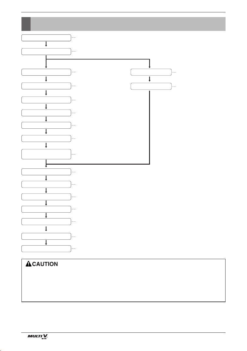
Installation Process
The foundation must be level even
Outdoor unit foundation work
Avoid short circuits and ensure
sufficient space is allowed for service
Installation of outdoor unit
Automatic addressing of indoor unit
In the final check for 24hours at 3.8 MPa(511.1 psi) there must be no drop in pressure.
Airtight test
Multiple core cable must not be used.
(suitable cable should be selected)
Electrical work
(connection circuits and drive circuits)
Make sure no gaps are left where
the insulating materials are joined
Heat insulation work
Make sure airflow is sufficient
Duct work
Adjust to downward gradient
Drain pipe work
Special attention to dryness,
cleanness and tightness
Refrigerant piping work
Check model name to make
sure the fitting is made correctly
Installation of indoor unit
Take account of gradient
of drain piping
Sleeve and insert work
Make relationship between outdoor, indoor, remote controller, and option connections clear.
(Prepare control circuit diagram)
Preparation of contract drawings
Indicate clearly who is to be responsible for switch settings
Determination of division work
The vacuum pump used must have a capacity of reaching at least 5 torr, more than 1 hour
Vacuum drying
Recharge correctly as calculated in this manual. and record the amount of added refrigerant
Additional charge of refrigerant
Make sure there are no gaps left between the facing materials used on the ceiling
Fit facing panels
Run each indoor unit in turn to make sure the pipe work has been fitted correctly
Test run adjustment
Explain the use of the system as clearly as possible to your customer and make sure all relevant
documentation is in order
Transfer to customer with explanation
Refer to automatic addressing flowchart
Preheat the crank case with the electrical heater for more than 6 hours.
(In case of outdoor temperature below 10C (50F)(
• The above list indicates the order in which the individual work operations are normally carried out but this
order may be varied where local conditions warrants such change.
• The wall thickness of the piping should comply with the relevant local and national regulations for the
designed pressure 3.8Mpa (511.1 psi).
• Since R410A is a mixed refrigerant, the required additional refrigerant must be charged in its liquid state.(If the
refrigerant is charged in its gaseous state, its composition changes and the system will not work properly.)
Outdoor Units Information
ENGLISH
Installation Manual 9
Outdoor Units Information
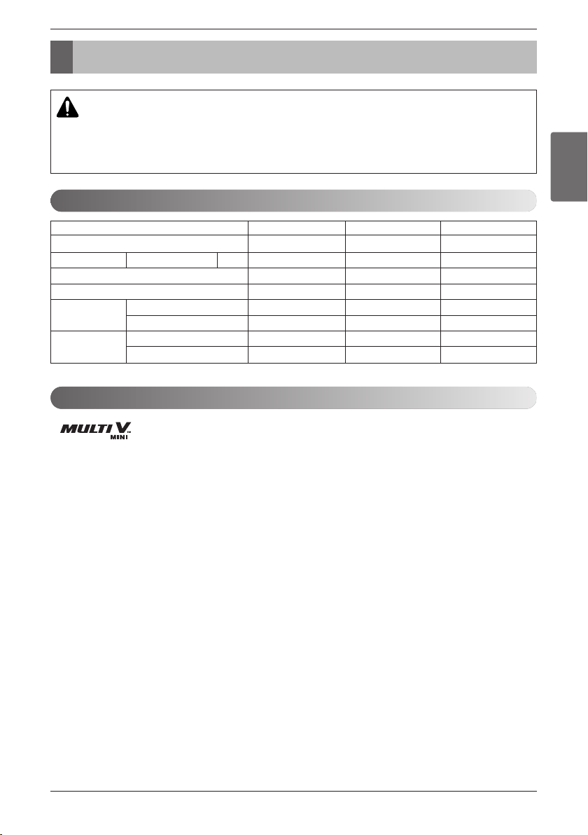
CAUTION
Ratio of the connectable Indoor Units to the Outdoor: Within 50 ~ 130%
Ratio of running Indoor Units to the Outdoor: Within 10 ~ 100%
A combination operation over 100% cause to reduce each indoor unit capacity.
Power Supply: Outdoor Unit (1Ø, 208/230V, 60Hz)
Connectable Indoor Unit
should be connected with "2 series" indoor unit only.
Ex) ARNU073TRC2
System(HP)
Model
Refrigerant Product charge kg(lbs)
Max. Connectable No. of Indoor Units
Net Weight kg(lbs)
Dimensions mm
(WxHxD) inch
Connecting Pipes
Liquid Pipes[mm(inch)]
Gas Pipes[mm(inch)]
45 6
ARUN036GS2 ARUN047GS2 ARUN053GS2
3.0(6.61) 3.0(6.61) 3.0(6.61)
68 9
106(233.7) 106(233.7) 106(233.7)
950×1,380×330 950×1,380×330 950×1,380×330
37.4×54.3×13 37.4×54.3×13 37.4×54.3×13
9.52(3/8) 9.52(3/8) 9.52(3/8)
15.88(5/8) 15.88(5/8) 19.05(3/4)
Before Installation
10 Outside Unit
Before Installation
• The refrigerant R410A has the property of higher operating pressure in comparison with R22.
Therefore, all materials have the characteristics of higher resisting pressure than R22 ones and this characteris-
tic should be also considered during the installation. R410A is an azeotrope of R32 and R125 mixed at 50:50, so
the ozone depletion potential (ODP) of R410A is 0. These days the developed countries have approved it as the
environment-friendly refrigerant and encouraged to use it widely to prevent environment pollution.
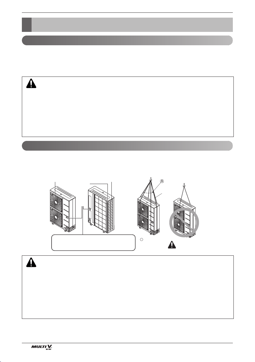
• When carrying the suspended, unit pass the ropes between legs of base panel under the unit.
• Always lift the unit with ropes attached at four points so that impact is not applied to the unit.
• Attach the ropes to the unit at an angle of 40° or less.
• Use only accessories and parts which are of the designated specification when installing.
CAUTION:
• The wall thickness of the piping should comply with the relevant local and national regulations for the designed
pressure 3.8MPa
• Since R410A is a mixed refrigerant, the required additional refrigerant must be charged in its liquid state.
• If the refrigerant is charged in its gaseous state, its composition changes and the system will not work properly.
• Do not place the refrigerant container under the direct rays of the sun to prevent it from exploding.
• For high-pressure refrigerant, any unapproved pipe must not be used.
• Do not heat pipes more than necessary to prevent them from softening.
• Be careful not to install wrongly to minimize economic loss because it is expensive in comparison with R22.
CAUTION:
Be very careful while carrying the product.
- Do not have only one person carry product if it is more than 20 kg (44.1 lbs).
-
PP bands are used to pack some products. Do not use them as a mean for transportation because they are dangerous.
- Do not touch heat exchanger fins with your bare hands. Otherwise you may get a cut in your hands.
- Tear plastic packaging bag and scrap it so that children cannot play with it Otherwise plastic packaging bag may
suffocate children to death.
- When carrying in Outdoor Unit, be sure to support it at four points. Carrying in and lifting with 3-point support may
make Outdoor Unit unstable, resulting in a fall.
Environment-friendly Alternative Refrigerant R410A
Transporting the Unit
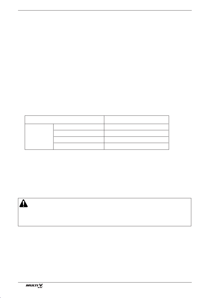
Air outlet grille Intake hole
Corner
Handle
Always hold the unit by the corners, as holding
it by the side intake holes on the casing may
cause them to deform.
Sub line
40° or less
A
WARNING
Select the Best Location
ENGLISH
Installation Manual 11
Select the Best Location
1. Select space for installing outdoor unit, which will meet the following conditions:
• No direct thermal radiation from other heat sources
• No possibility of annoying neighbors by noise from unit
• No exposition to strong wind
• With strength which bears weight of unit
• Note that drain flows out of unit when heating
• With space for air passage and service work shown next
• Because of the possibility of fire, do not install unit to the space where generation, inflow, stagnation, and
leakage of combustible gas is expected.
• Avoid unit installation in a place where acidic solution and spray (sulfur) are often used.
• Do not use unit under any special environment where oil, steam and sulfuric gas exist.
• It is recommended to fence round the outdoor unit in order to prevent any person or animal from accessing
the outdoor unit.
• If installation site is area of heavy snowfall, then the following directions should be observed.
- Make the foundation as high as possible.
- Fit a snow protection hood.
2. Select installation location considering following conditions to avoid bad condition when additionally perform-
ing defrost operation.
• Install the outdoor unit at a place well ventilated and having a lot of sunshine in case of installing the product
at a place with a high humidity in winter (near beach, coast, lake, etc).
(Ex) Rooftop where sunshine always shines.
• Performance of heating will be reduced and preheat time of the indoor unit may be lengthened in case of
installing the outdoor unit in winter at following location:
- Shade position with a narrow space
- Location with much moisture in neighboring floor.
- Location with much humidity around.
- Location where ventilation is good.
It is recommended to install the outdoor unit at a place with a lot of sunshine as possible as.
- Location where water gathers since the floor is not even.
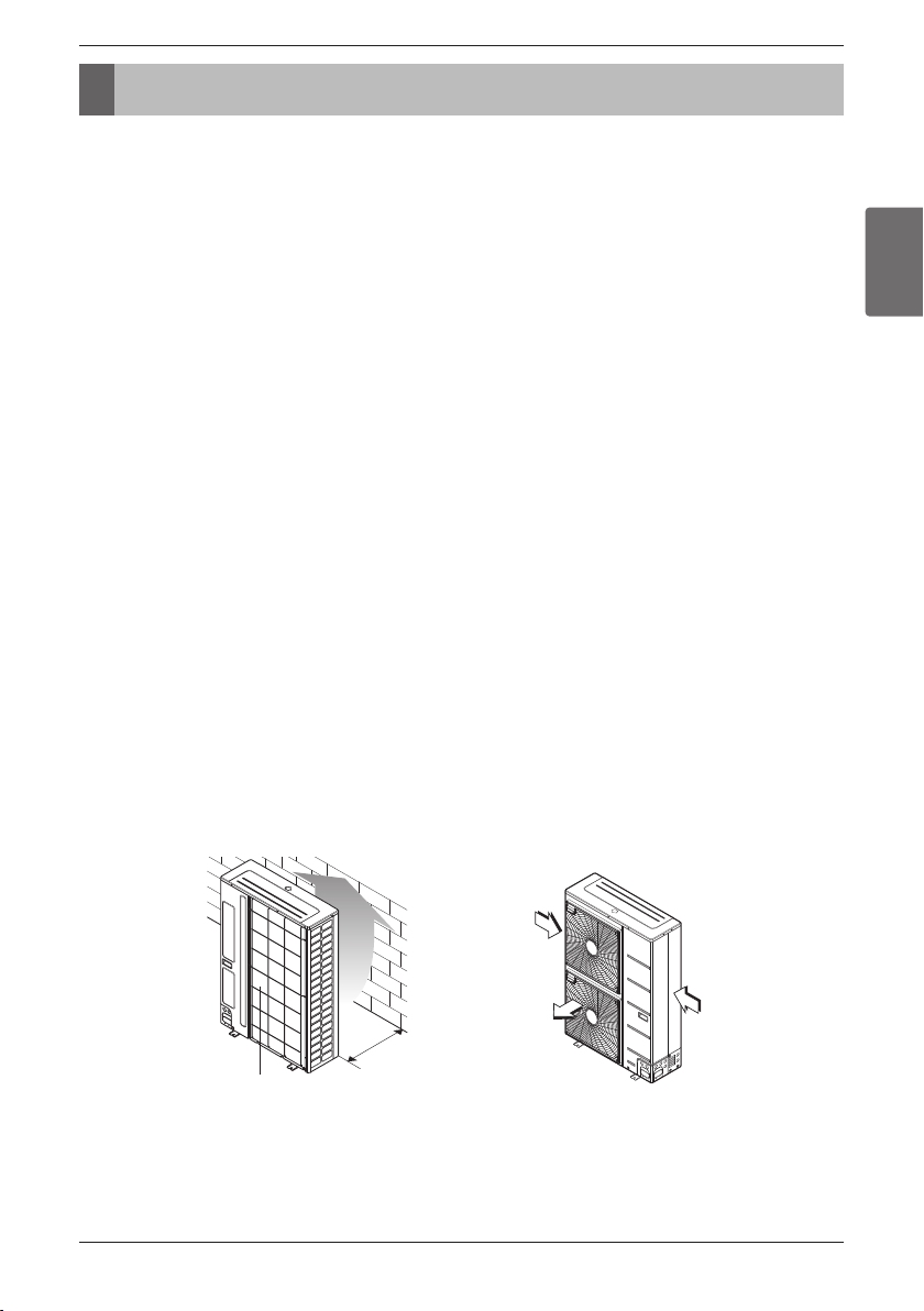
3. When installing the outdoor unit in a place that is constantly exposed to a strong wind like a coast or on a
high story of a building, secure a normal fan operation by using a duct or a wind shield.
• Install the unit so that its discharge port faces to the wall of the building.
Keep a distance 500 mm (19-5/8 inch) or more between the unit and the wall surface.
• Supposing the wind direction during the operation season of the air conditioner, install the unit so that the
discharge port is set at right angle to the wind direction.
Air inlet grille
500 mm
(19-5/8 inch)
Blown
air
Strong
wind
Strong
wind
Turn the air outlet side toward the building's wall,
fence or windbreak screen.
Set the outlet side at a right angle
to the direction of the wind.
Installation Space
12 Outside Unit
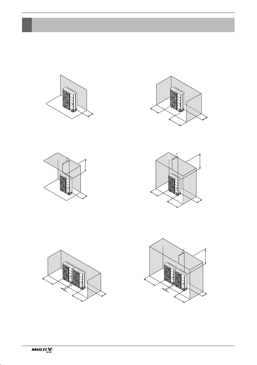
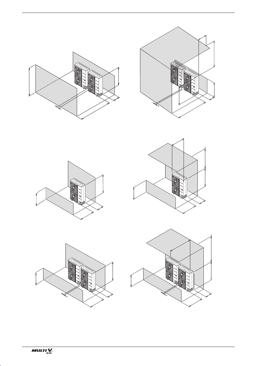
Installation Space
• The following values are the least space for installation.
If any service area is needed for service according to field circumstance, obtain enough service space.
• The unit of values is mm.
n In case of obstacles on the suction side
1. Stand alone installation
2. Collective installation
100(3-15/16)
or more
100(3-15/16)
or more
100(3-15/16)
or more
100(3-15/16)
or more
1000 (39-1/4)
or more
100(3-15/16)
or more
500(19-5/8)
or less
500(19-5/8)
or less
500(19-5/8)
or less
1000 (39-1/4)
or more
1000 (39-1/4)
or more
150(3-15/16)
or more
150(3-15/16)
or more
150(3-15/16)
or more
100(3-10/11)
or more
100(3-15/16)
or more
200(7-7/8)
or more
200(7-7/8)
or more
1000 (39-1/4)
or more
1000 (39-1/4)
or more
300(11-7/8)
or more
300(11-7/8)
or more
Unit:mm(inch)
Unit:mm(inch)
Installation Space
ENGLISH
Installation Manual 13
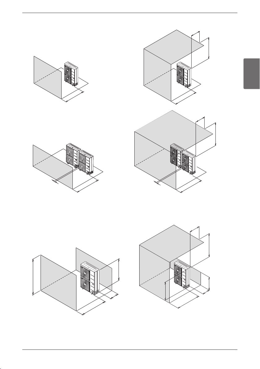
n In case of obstacles on the discharge side
1. Stand alone installation
2. Collective installation
500(19-5/8) or more
500(19-5/8)
or less
1000 (39-1/4)
or more
1000 (39-1/4)
or more
1000 (39-1/4)
or more
500(19-5/8) or more
1000 (39-1/4)
or more
1000 (39-1/4)
or more
H
L
L > HL > H
100(3-15/16)
or more
500(19-5/8)
or more
500(19-5/8) or less
L
H
250 (9-7/8)
or more
1000 (39-1/4)
or more
100(3-15/16)
or more
100(3-15/16)
or more
Unit:mm(inch)
Unit:mm(inch)
500(19-5/8) or less
n In case of obstacles on the suction and the discharge side
Ú Obstacle height of discharge side is higher than the unit
1. Stand alone installation
Installation Space
14 Outside Unit
2. Collective installation
2. Collective installation
Ú Obstacle height of discharge side is lower than the unit
1. Stand alone installation
L > H L > H
L H L H
L H L H
L
H
500(19-5/8)
or less
L
H
1250(49-1/4)
or more
H
L
100(3-15/16)
or more
500(19-5/8)
or less
500(19-5/8) or less
H
L
1000 (39-1/4)
or more
1000 (39-1/4)
or more
H
L
300(11-7/8)
or more
300(11-7/8)
or more
300(11-7/8)
or more
300(11-7/8)
or more
300(11-7/8)
or more
1500(59)
or more
500(19-5/8)
or less
1000 (39-1/4)
or more
1000 (39-1/4)
or more
1000 (39-1/4)
or more
H
L
1500(59)
or more
100(3-15/16)
or more
100(3-15/16)
or more
100(3-15/16)
or more
100(3-15/16)
or more
Unit:mm(inch)
Unit:mm(inch)
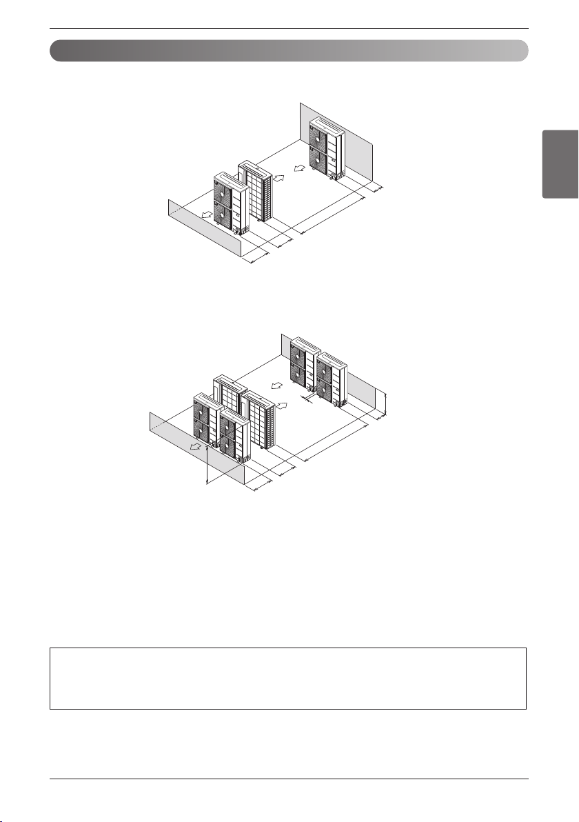
Installation Space
ENGLISH
Installation Manual 15
Collective / Continuous Installation for roof top use
Space required for collective installation and continuous installation: When installing several units, leave space
between each block as shown below considering passage for air and people.
1. One row of stand alone installation
2. Rows of collective installation (2 or more)
• L should be smaller than H
100(3-15/16)
or more
2000(78-3/4)
or more
200(7-7/8)
or more
1000 (39-1/4)
or more
L
300(11-7/8)
or more
3000(118-1/8)
or more
H
600(23-5/8)
or more
1500(59)
or more
100(3-15/16) or
more
L ≤ H
Unit:mm(inch)
Unit:mm(inch)
Seasonal wind and cautions in winter
• Sufficient measures are required in a snow area or severe cold area in winter so that product can be operated well.
• Get ready for seasonal wind or snow in winter even in other areas.
• Install a suction and discharge duct not to let in snow or rain.
• Install the outdoor unit not to come in contact with snow directly. If snow piles up and freezes on the air suction hole,
the system may malfunction. If it is installed at snowy area, attach the hood to the system.
• Install the outdoor unit at the higher installation console by 500mm(19-11/16) than the average snowfall (annual aver-
age snowfall) if it is installed at the area with much snowfall.
1. The height of H frame must be more than 2 times the snowfall and its width shall not exceed the width of the
product. (If width of the frame is wider than that of the product, snow may accumulate)
2. Don't install the suction hole and discharge hole of the Outdoor Unit facing the seasonal wind.
Installation
16 Outside Unit
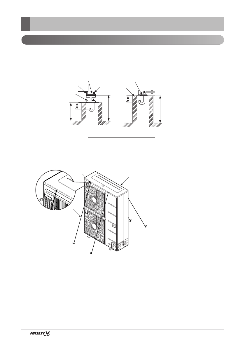
Installation
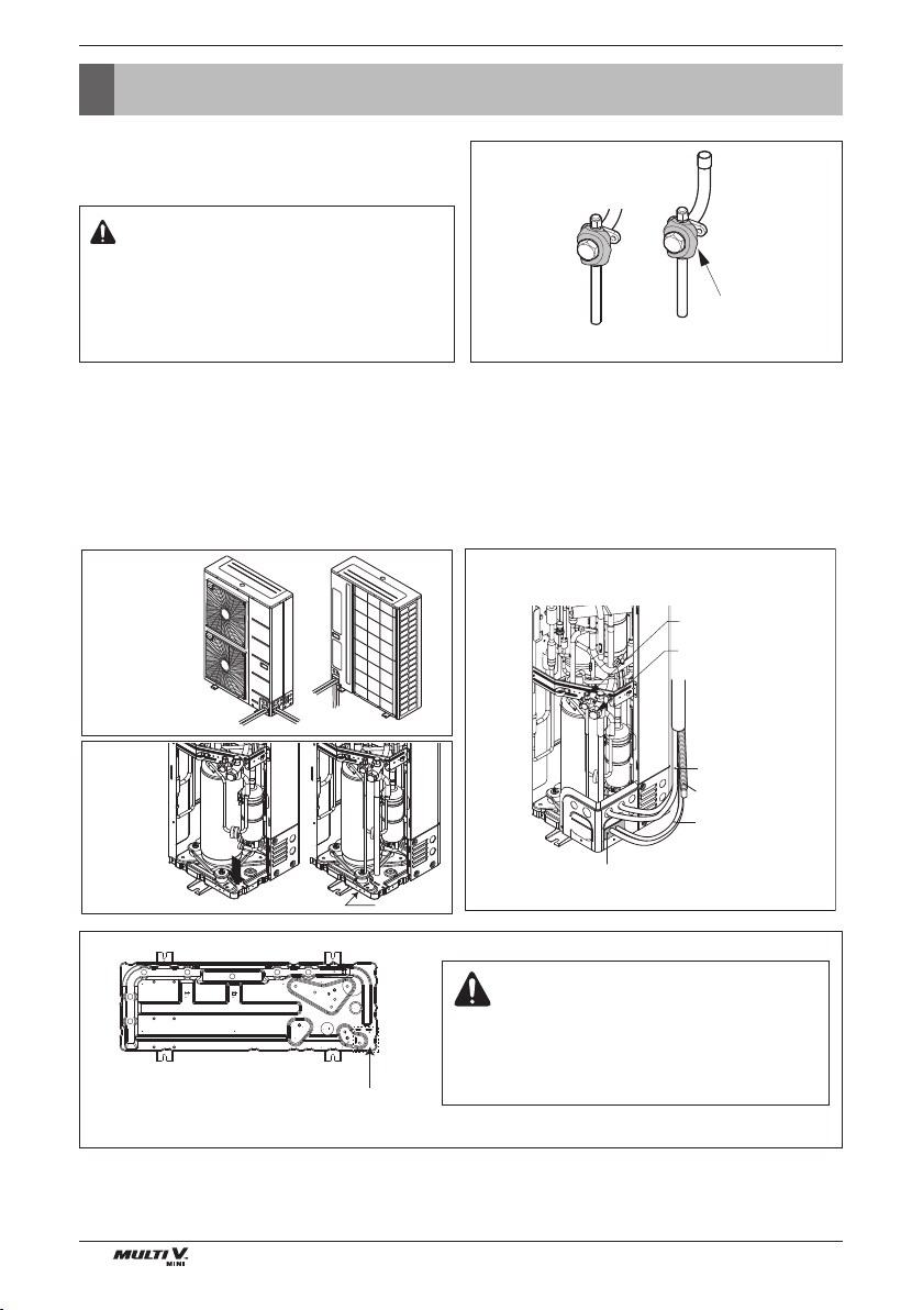
Foundation for Installation
If it is necessary to prevent the unit from falling over, install as shown in the figure.
• Prepare all 4 wires as indicated in the drawing
• Unscrew the top plate at the 4 location indicated A and B
• Put the screws through the nooses and screw them back tight
A
B
C
Foundation bolt executing method
200 (7-7/8)
Nut
75 (3)
75 (3)
200 (7-7/8)
Spring washer
Frame
Anti-vibration
materials
Four bolt are
required
3 thread ridges
H-Beam
Concrete
base
100(3-15/16)
A : Location of the 2 fixation holes on
the front side of the unit
B : Location of the 2 fixation holes on
the rear side of the unit
C : wires
• Fix the unit tightly with bolts as shown below so that unit will not fall down due to earthquake or gust.
• Use the H-beam support as a base support
•
Noise and vibration may occur from the floor or wall since vibration is transferred through the installation part depending
on installation status. Thus, use anti-vibration materials (cushion pad) fully (The base pad shall be more than
200 mm (7-7/8 inch)).
Installation
ENGLISH
Installation Manual 17
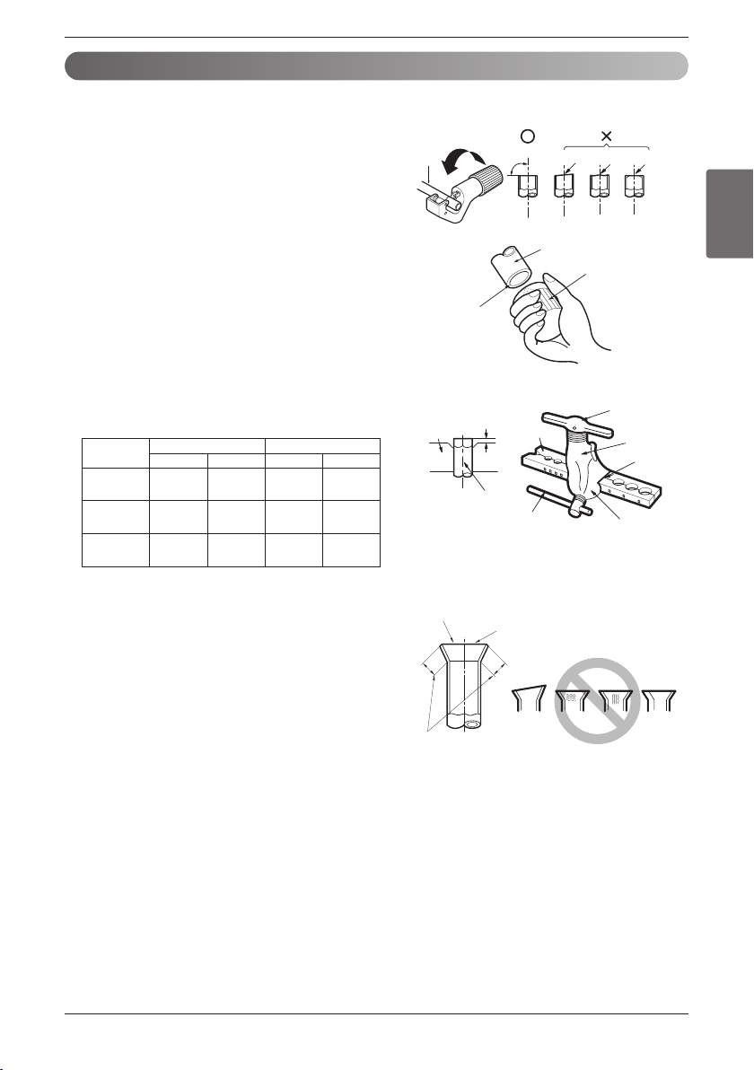
Preparation of Piping
1) Cut the pipes and the cable.
n Use the accessory piping kit or the pipes purchased
locally.
n Measure the distance between the indoor and the out-
door unit.
n Cut the pipes a little longer than measured distance.
n Cut the cable 1.5m longer than the pipe length.
2) Burrs removal
n Completely remove all burrs from the cut cross section
of pipe/tube.
n Put the end of the copper tube/pipe to downward direc-
tion as you remove burrs in order to avoid to let burrs
drop in the tubing.
3) Flaring work
n Carry out flaring work using flaring tool as shown right.
Firmly hold copper tube in a bar(or die) as indicated
dimension in the table above.
4) Check
n Compare the flared work with figure right.
n If flare is noted to be defective, cut off the flared section
and do flaring work again.
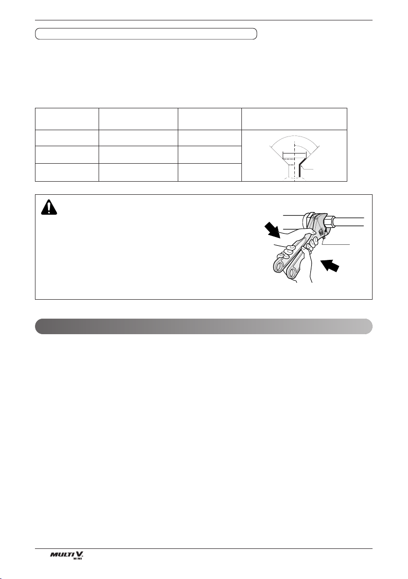
Main cause of gas leakage is defect in flaring work. Carry out correct flaring work in the following procedure.
Pipe " A "
Gas Liquid Gas Liquid
<5.6(19,100) 12.7(1/2) 6.35(1/4)
1.6~1.8 1.1~1.3
(0.63~0.71) (0.43~0.51)
<16.0(54,600) 15.88(5/8) 9.52(3/8)
1.6~1.8 1.5~1.7
(0.63~0.71) (0.59~0.67)
<22.4(76,400) 19.05(3/4) 9.52(3/8)
1.9~2.1 1.5~1.7
(0.75~0.83) (0.59~0.67)
Indoor unit
[kW(Btu/h]
Copper
tube
90°
Slanted Uneven Rough
Pipe
Reamer
Point down
Bar
Copper pipe
Clamp handle
Red arrow mark
Cone
Yoke
Handle
Bar
"A"
Inclined
Inside is shining without scratches.
Smooth all round
Even length
all round
Surface
damaged
Cracked Uneven
thickness
= Improper flaring =
Unit : mm(inch)
Installation
18 Outside Unit
Precautions when connecting pipes
• See the following table for flare part machining dimensions.
• When connecting the flare nuts, apply refrigerant oil to the inside and outside of the flares and turn them three
or four times at first. (Use ester oil or ether oil.)
• See the following table for tightening torque.(Applying too much torque may cause the flares to crack.)
• After all the piping has been connected, use nitrogen to perform a gas leak check.
CAUTION
Always use a charge hose for service port connection.
After tightening the cap, check that no refrigerant leaks are
present.
When loosening a flare nut, always use two wrenches in
combination, When connecting the piping, always use a spanner
and torque wrench in combination to tighten the flare nut.
When connecting a flare nut, coat the flare(inner and outer faces)
with oil for R410A(PVE) and hand tighten the nut 3 to 4 turns as
the initial tightening.
FLARE SHAPE and FLARE NUT TIGHTENING TORQUE
90°
±2
45°
±2
A
R=0.4~0.8
Pipe size(mm/inch) Tightening torque
A (mm /inch) flare shape
(Kgf·m/lbf·ft)
Ø9.52 (3/8) 3.4-4.2(24.6-30.4) 12.6-13.0 (1/2)
Ø12.7 (1/2) 5.5-6.6(39.8-47.7) 15.8-16.2 (5/8)
Ø15.88 (5/8) 6.3-8.2(45.6-59.3) 19.0-19.4(3/4)
Union
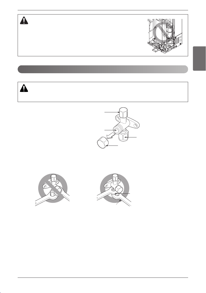
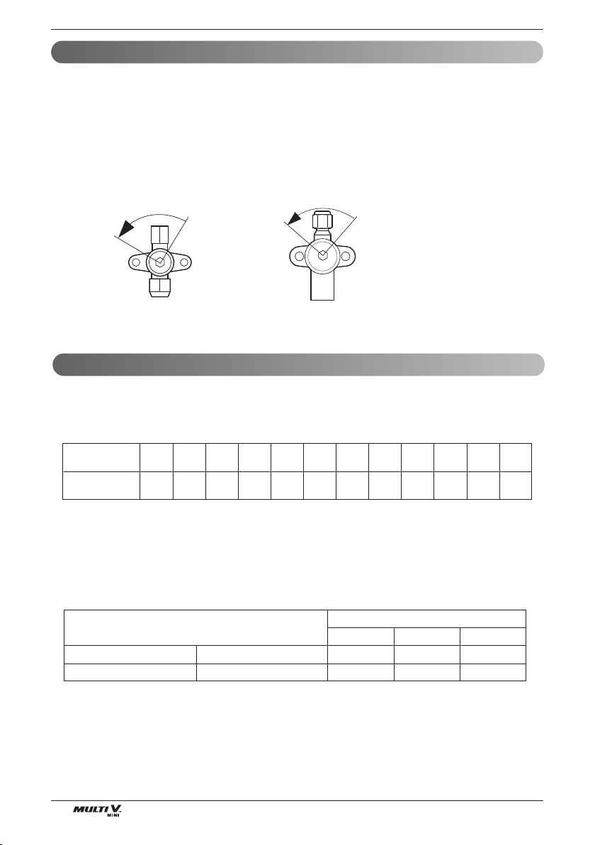
1. Remove the cap and turn the valve counter clockwise with the hexagon wrench.
2. Turn it until the shaft stops.
Do not apply excessive force to the shutoff valve. Doing so may break the valve body, as the valve is not a
backseat type. Always use the special tool.
3. Make sure to tighten the cap securely.
Opening shutoff valve
Installation
ENGLISH
Installation Manual 19
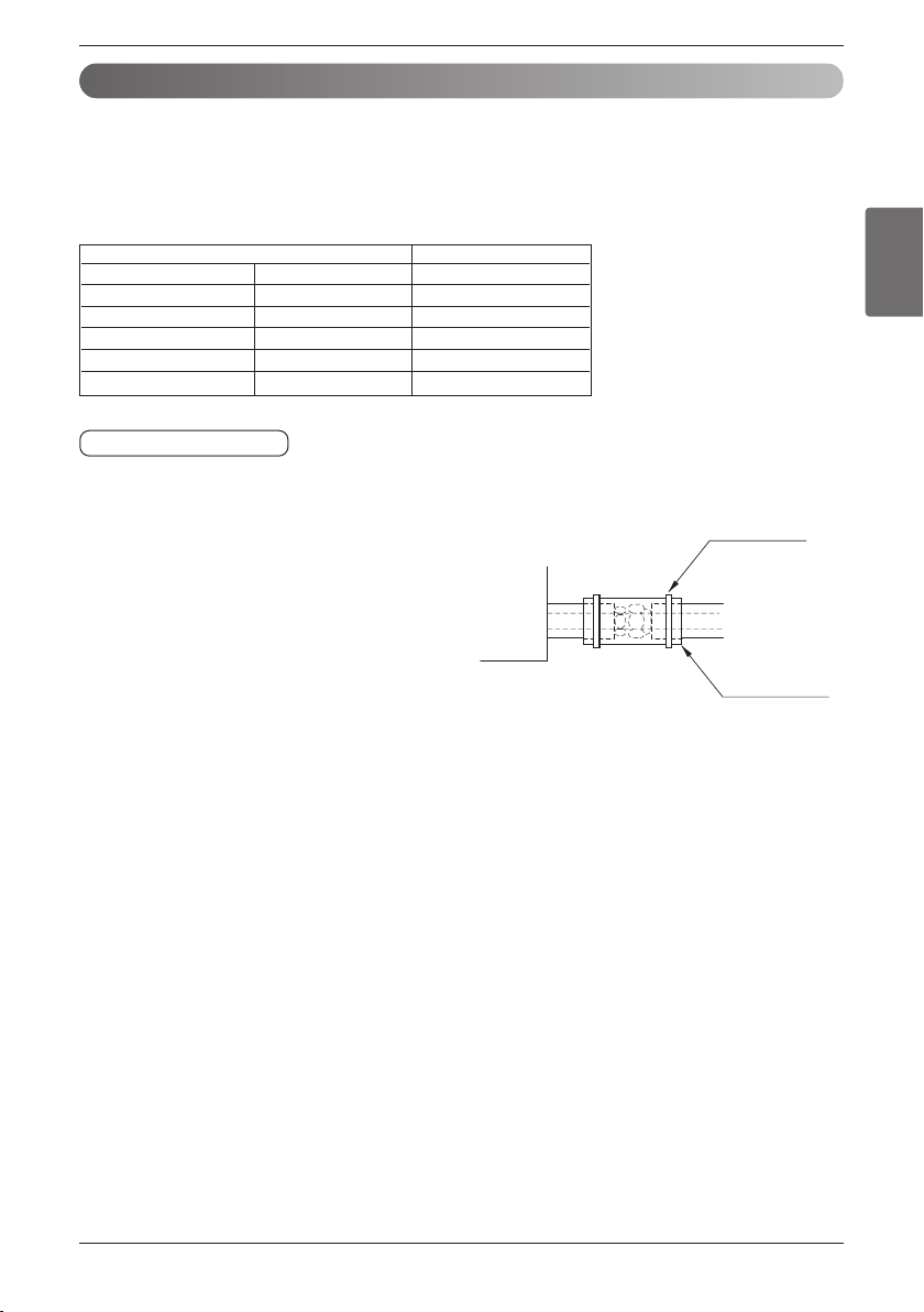
1. Use the heat insulation material for the refrigerant piping which has an excellent heat-resistance
(over 248°F).
2. Precautions in high humidity circumstance:
This air conditioner has been tested according to the
"ISO Conditions with Mist" and confirmed that there is
not any default. However, if it is operated for a long
time in high humid atmosphere (dew point tempera-
ture: more than 73°F), water drops are liable to fall. In
this case, add heat insulation material according to the
following procedure:
• Heat insulation material to be prepared... EPDM
(Ethylene Propylene Diene Methylene)-over 248°F
the heat-resistance temperature.
• Add the insulation over 10mm thickness at high humidity environment.
Indoor unit
Thermal insulator
(accessory)
Fastening band
(accessory)
Refrigerant piping
HEAT INSULATION
1. Remove the cap and turn the valve clockwise with the hexagon wrench.
2. Securely tighten the valve until the shaft contacts the main body seal.
3. Make sure to tighten the cap securely.
* For the tightening torque, refer to the table on the below.
Tightening torque
Outside diameter Torque
mm inch N
.
m(kgf•cm)
Ø6.35 1/4 18~25(180~250)
Ø9.52 3/8 34~42(340~420)
Ø12.7 1/2 55~66(550~660)
Ø15.88 5/8 63~82(630~820)
Ø19.05 3/4 99~121(990~1210)
Closing shutoff valve
Refrigerant Piping
20 Outside Unit
Refrigerant Piping
n Connecting the pipes to the outdoor unit
n Possible direction for field piping
• The installation piping is connectable in four direc-
tions.(refer to figure 1)
• When connecting in a downward direction, knock out
the knockout hole of the base pan.
(refer to figure2, figure3)
n Preventing foreign objects from
entering (Figure 4)
• Plug the pipe through-holes with putty or insulation
material(procured locally)to stop up all gaps,as
shown in the figure 3.
• Insects or small animals entering the outdoor unit
may cause a short circuit in the electrical box.
• Braze suitable field piping with service valve of gas pipe.
<Gas pipe>
<Liquid pipe>
Wet towel
Forward
Sideways
Backward
Base pan
Downward
Knock-out
<Figure 1>
<Figure 2>
<Figure 4>
Gas side piping
(Bigger Dia.)
Liquid side piping
(Smaller Dia.)
Putty or insulating material
(produced locally)
Drain hose
Connecting wire
Connection pipe
CAUTION
Take care so that there is no thermal damage on the
service valves of the outdoor unit.
(Especially packing part of service port.) Wrap the
service valve with a wet towel when brazing it as
shown figure above.
Pipe knock
out during the
ground piping.
<Figure 3>
CAUTION
• You should not dame pipe/base during the work of
pipe knock out.
• Operate piping work removing burr after pipe knock
out.
Refrigerant Piping
ENGLISH
Installation Manual 21
CAUTION
• Make sure that pipe doesn't contact with the compressor terminal cover
and comp bolt.
• Always insulate the liquid and gas-side field piping and branch.
Cautions for Handling Service Valve
CAUTION
Make sure to keep the valve open during operation
• The service valves are closed at shipment from the factory
The names of parts of the service valve are
shown in the figure.
• since the side boards may be deformed if only a torque wrench is used when loosening or tightening flare nuts,
always lock the shut-off valve with a wrench and then use a torque wrench.
Do not place wrenches on the valve cover.
Do not apply force on the valve cover, this may result in a refrigerant leak.
1
2
3
4
1
2
1. Service point
2. Shut-off Valve
3. Filed piping connection
4. Valve cover
1. Spanner
2. Torque wrench
Refrigerant Piping
22 Outside Unit
How to Use the Shut-Off Valve
Use hexagonal wrenches 4mm or 6mm (1/6 inch or 1/4 inch)
• Opening the valve
1. Place the hexagon wrench on the valve bar and turn counter-clockwise.
2. Stop when the valve bar no longer turns. It is now open.
• Closing the valve
1. Place the hexagon wrench on the valve bar and turn clockwise.
2. Stop when the valve bar no longer turns. It is now closed.
<Liquid pipe>
Direction to open
<Gas pipe>
Direction to open
1. Use the following materials for refrigerant piping.
• Material: Seamless phosphorous deoxidized copper pipe
• Wall thickness : Comply with the relevant local and national regulations for the designed pressure
3.8 Mpa(551.1 psi). We recommend the following table as the minimum wall thickness.
2. Commercially available piping often contains dust and other materials. Always blow it clean with a dry inert
gas.
3. Use care to prevent dust, water or other contaminants from entering the piping during installation.
4. Reduce the number of bending portions as much as possible, and make bending radius as big as possible.
5. Always use the branch piping set shown below, which are sold separately.
Caution
ARBLN01621 ARBLN03321 ARBL054 ARBL057 ARBL1010
ARBLN07121 ARBLN14521 ARBL104 ARBL107 ARBL2010
Y branch
Header
4 branch 7 branch 10 branch
6.35(1/4) 9.52(3/8) 12.7(1/2) 15.88(5/8) 19.05(3/4) 22.2(7/8) 25.4(1) 28.58(1-1/8) 31.8(1-1/4) 34.9(1-3/8) 38.1(1-1/2) 41.3(1-5/8)
0.8(0.03) 0.8(0.03) 0.8(0.03) 0.99(0.03) 0.99(0.03) 0.99(0.03) 0.99(0.03) 0.99(0.03) 1.1(0.04) 1.21(0.04) 1.35(0.05) 1.43(0.05)
Minimum thickness
[mm(inch)]
Outer diameter
[mm(inch)]
Refrigerant Piping
ENGLISH
Installation Manual 23
To Outdoor Unit
Sealed Piping
A
A
B
A
B
6. If the diameters of the branch piping of the designated refrigerant piping differs, use a pipe cutter to cut
the connecting section and then use an adapter for connecting different diameters to connect the piping.
7. Always observe the restrictions on the refrigerant piping (such as rated length, difference in height, and
piping diameter).
Failure to do so can result in equipment failure or a decline in heating/cooling performance.
8. A second branch cannot be made after a header. (These are shown by .)
9. The Multi V will stop due to an abnormality like excessive or insufficient refrigerant. At such a time, always
properly charge the unit. When servicing, always check the notes concerning both the piping length and
the amount of additional refrigerant.
10. Never use refrigerant to perform an air purge. Always evacuate using a vacuum pump.
11. Always insulate the piping properly. Insufficient insulation will result in a decline in heating/cooling perfor-
mance, drip of condensate and other such problems.
12. When connecting the refrigerant piping, make sure the service valves of the Outdoor Unit is completely
closed (the factory setting) and do not operate it until the refrigerant piping for the Outdoor and Indoor
Units has been connected, a refrigerant leakage test has been performed and the evacuation process
has been completed.
13. Always blow nitrogen into pipe which is brazed. Always use a non-oxidizing brazing material for brazing
the parts and do not use flux. If not, oxidized film can cause clogging or damage to the compressor unit
and flux can harm the copper piping or refrigerant oil.
3
2
1
45
6
1 Refrigerant piping 4 Taping
2 Pipe to be brazed 5 Valve
3 Nitrogen 6 Pressure-reducing valve
Refrigerant Piping
24 Outside Unit
WARNING
When installing and moving the air conditioner to another site, be sure to make recharge refrigerant
after perfect evacuation.
- If a different refrigerant or air is mixed with the original refrigerant, the refrigerant cycle may malfunction and
the unit may be damaged.
- After selecting diameter of the refrigerant pipe to suit total capacity of the indoor unit connected after
branching, use an appropriate branch pipe set according to the pipe diameter of the indoor unit and the
installation pipe drawing.
WARNING
Do not use anti-oxidants when brazing the pipe joints. Residue can clog pipes and break equipment.
Refrigerant Piping
ENGLISH
Installation Manual 25
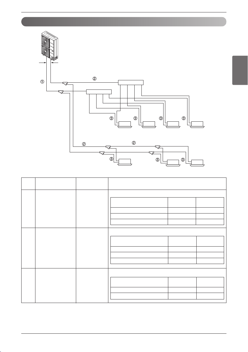
Selection of Refrigerant Piping
Selection of pipe sizeName
Size of main pipe
Pipe size of between branching sections
Connecting pipe size of indoor unit
Piping partsNo.
Outdoor unit
↓
1st branching section
Branching section
↓
Branching section
Branching section
↓
Indoor unit
Main pipe
①
②
③
Branching pipe
Indoor unit
connecting pipe
Outdoor unit capacity type
Liquid pipe Gas pipe
[mm(inch)] [mm(inch)]
4 HP Ø9.52(3/8) Ø15.88(5/8)
5 HP Ø9.52(3/8) Ø15.88(5/8)
6 HP Ø9.52(3/8) Ø19.05(3/4)
Indoor unit capacity[kW(Btu/h)]
Liquid pipe Gas pipe
[mm(inch)] [mm(inch)]
≤ 5.6(19,100) Ø6.35(1/4) Ø12.7(1/2)
< 16.0(54,000) Ø9.52(3/8) Ø15.88(5/8)
Indoor unit capacity[kW(Btu/h)]
Liquid pipe Gas pipe
[mm(inch)] [mm(inch)]
≤ 5.6(19,100) Ø6.35(1/4) Ø12.7(1/2)
< 16.0(54,600) Ø9.52(3/8) Ø15.88(5/8)
< 22.4(76,400) Ø9.52(3/8) Ø19.05(3/4)
Outdoor unit
Gas pipe
Main pipe
Liquid pipe
Branching
pipe
Branching
pipe
Indoor unit
Refrigerant Piping
26 Outside Unit
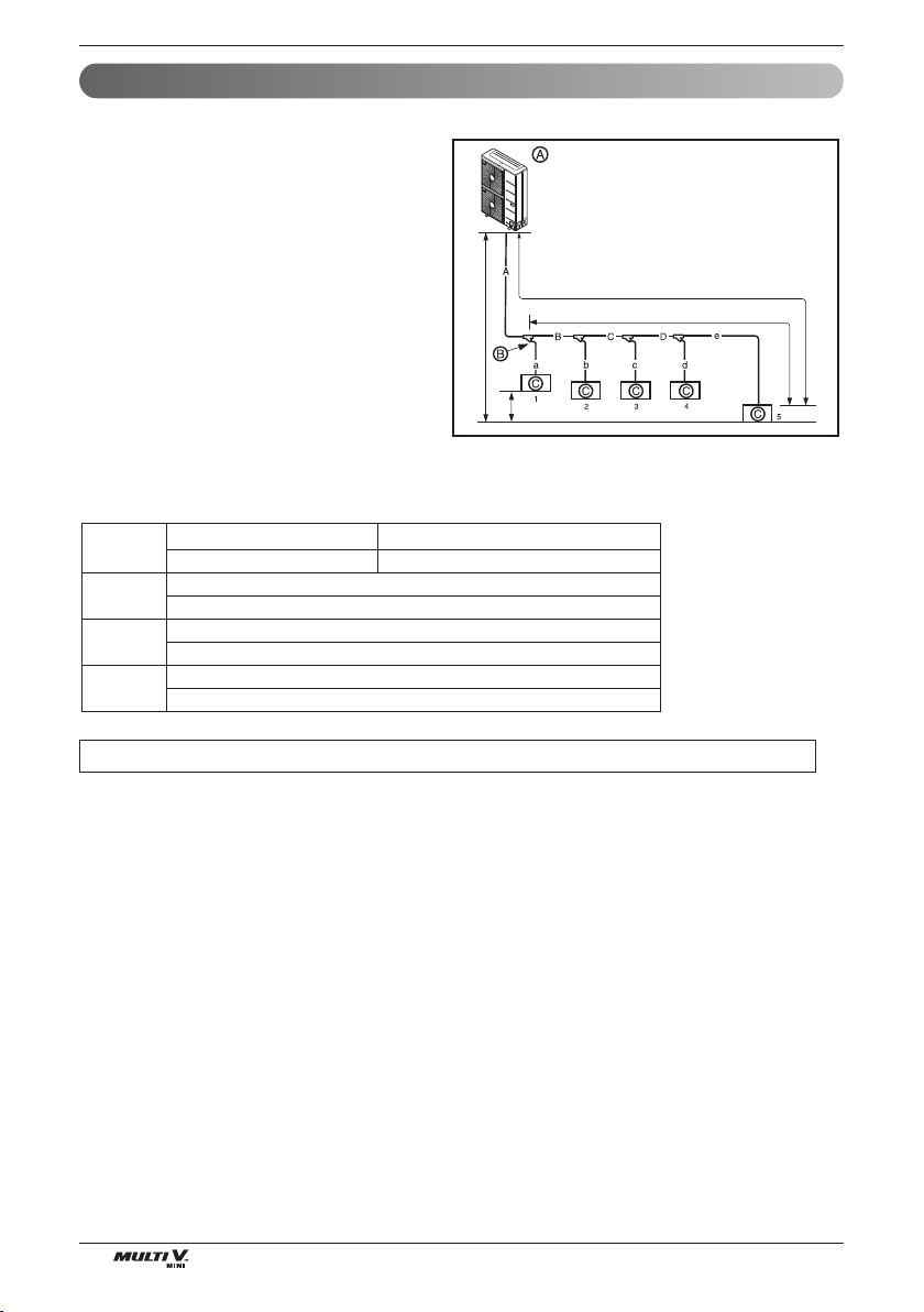
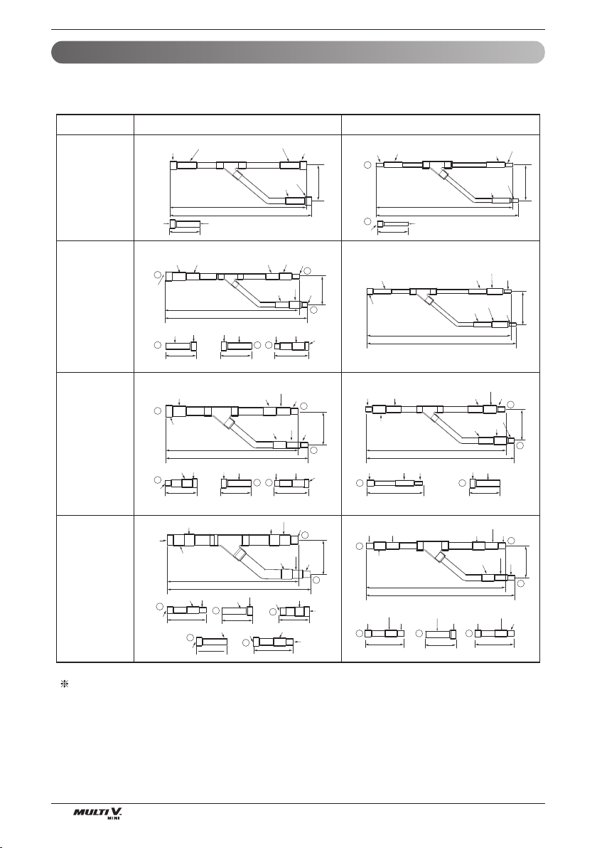
Allowable Length/Height Difference of Refrigerant Piping
n Y Branch Method
Example : 5 Indoor Units connected
Ⓐ : Outdoor Unit
Ⓑ : 1st branch (Y branch)
Ⓒ : Indoor Units
L150 (492)
H50 (164)
l 40 (131)
[Unit:m(ft)]
h15(49)
Ú Total pipe length = A+B+C+D+a+b+c+d+e ≤ 300m(984ft)
• * :
Assume equivalent pipe length of Y branch to be 0.5m(1.6ft), that of header to be 1m(3.3ft), calculation purpose
Longest pipe length Equivalent pipe length
A+B+C+D+e ≤ 150m(492ft) * A+B+C+D+e ≤ 175m(574ft)
Longest pipe length after 1st branch
B+C+D+e ≤ 40m(131ft)
Difference in height(Outdoor Unit ÷ Indoor Unit)
H ≤ 50m(164ft)
Difference in height (Indoor Unit ÷ Indoor Unit)
h ≤ 15m(49ft)
L
l
H
h
Refrigerant Piping
ENGLISH
Installation Manual 27
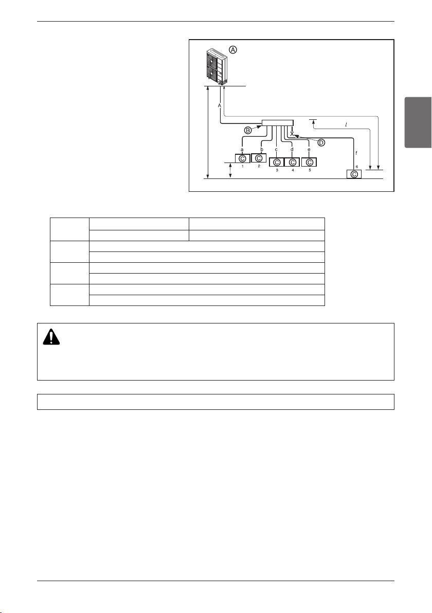
n Header Method
Example : 6 Indoor Units connected
Ⓐ : Outdoor Unit
Ⓑ : 1st branch
Ⓒ : Indoor Units
Ⓓ : Sealed piping
L150 (492)
H50 (164)
40 (131)
h15(49)
[Unit:m(ft)]
WARNING
Pipe length after header branching (a~f)
It is recommended that difference in length of the pipes connected to the Indoor Units is minimized.
Performance difference between Indoor Units may occur.
Longest pipe length * Equivalent pipe length
A+f ≤ 150m(492ft) A+f ≤ 175m(574ft)
Longest pipe length after 1st branch
f ≤ 40m(131ft)
Difference in height(Outdoor Unit ÷ Indoor Unit)
H ≤ 50m(164ft)
Difference in height (Indoor Unit ÷ Indoor Unit)
h ≤ 15m(49ft)
L
l
H
h
Ú Total pipe length = A+a+b+c+d+e+f ≤ 300m(984ft)
• * :
Assume equivalent pipe length of Y branch to be 0.5m(1.6ft), that of header to be 1m(3.3ft), calculation purpose
Refrigerant Piping
28 Outside Unit
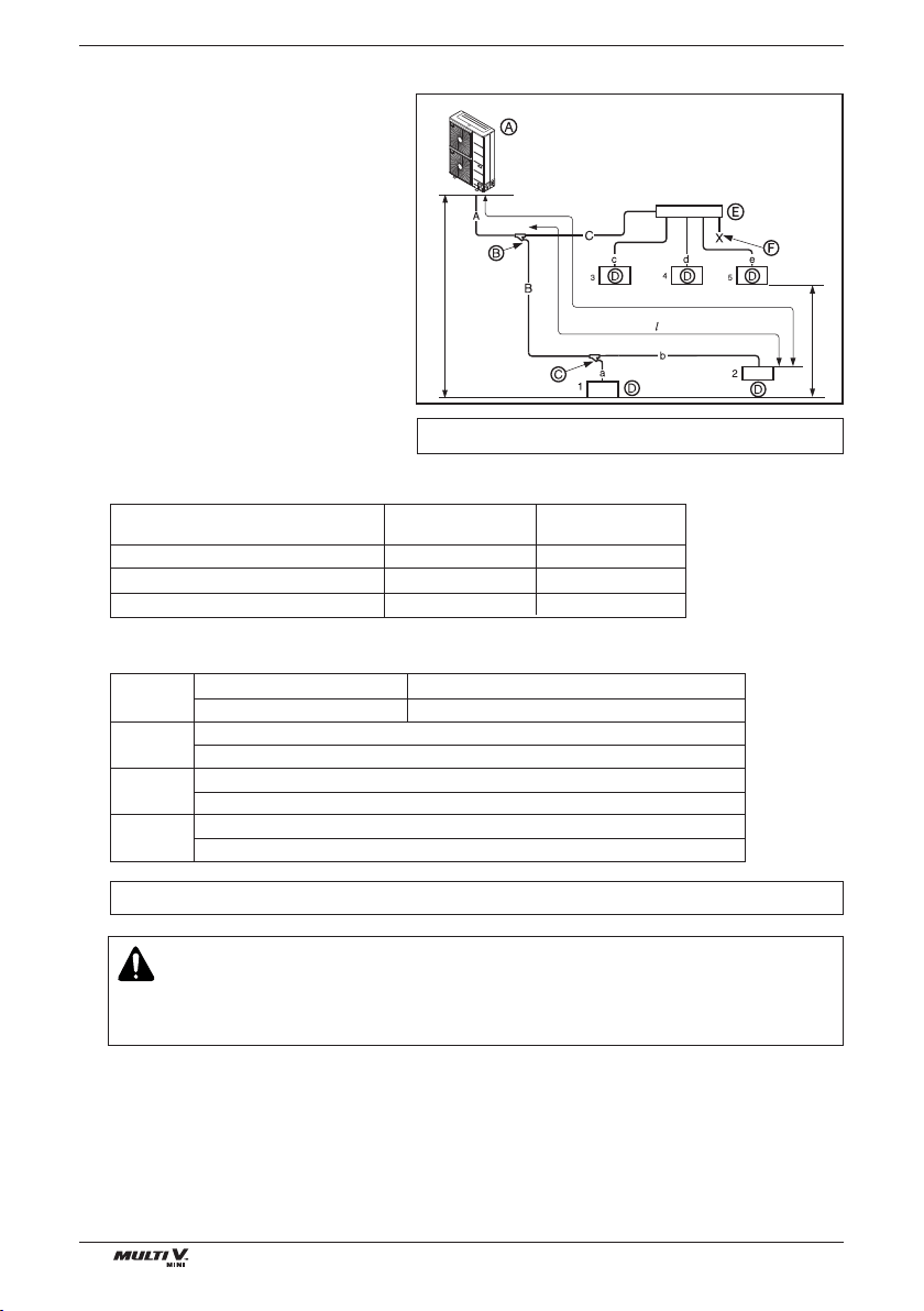
n Combination of Y branch/header method
Example : 5 Indoor Units connected
Ⓐ : Outdoor Unit
Ⓑ : 1st branch (Y branch)
Ⓒ : Y branch
Ⓓ : Indoor Unit
Ⓔ : Header
Ⓕ : Sealed piping
L150 (492)
40 (131)
H50 (164)
[Unit:m(ft)]
h15(49)
Branch pipe can not be used after header
Ú Refrigerant pipe diameter from branch to branch (B,C)
Ú Total pipe length = A+B+C+a+b+c+d+e ≤ 300m(984ft)
Longest pipe length * Equivalent pipe length
A+B+b ≤ 150m(492ft) A+B+b ≤ 175m(574ft)
Longest pipe length after 1st branch
B+b ≤ 40m(131ft)
Difference in height(Outdoor Unit ÷ Indoor Unit)
H ≤ 50m(164ft)
Difference in height (Indoor Unit ÷ Indoor Unit)
h ≤ 15m(49ft)
L
l
H
h
Downward Indoor Unit total capacity
[kW(Btu/h)]
≤5.6(19,100) Ø6.35(1/4) Ø12.7(1/2)
<16(54,600) Ø9.52(3/8) Ø15.88(5/8)
<22.4(76,400) Ø9.52(3/8) Ø19.05(3/4)
Liquid pipe
[mm(inch)]
Gas pipe
[mm(inch)]
• * :
Assume equivalent pipe length of Y branch to be0.5m(1.6ft), that of header to be 1m(3.3ft), calculation purpose
WARNING
It is recommended that difference of piping length for pipes connected to the Indoor Unit is
minimized. Performance difference between Indoor Units may occur.
Refrigerant Piping
ENGLISH
Installation Manual 29
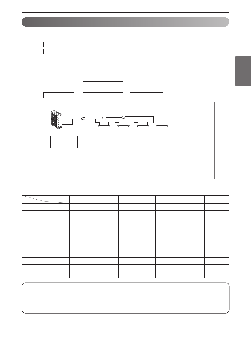
The Amount of Refrigerant
The calculation of the additional charge should take into account the length of pipe.
Additional charge(lbs)
Total charge(lbs) Product charge(lbs) Additional charge(lbs)
Product charge(lbs)
=
x 0.041(lbs/ft)
Length(ft) of
liquid pipe of Ø 3/8 in
+
x 0.015(lbs/ft)
Length(ft) of
liquid pipe of Ø1/4 in
+
Correction factor of
outdoor unit
+
Correction factor of
Indoor unit
=+
Example : 5HP
Additional charge amount R (lbs)
= (Lx x 0.015(lbs/ft) + (Ly x 0.041(lbs/ft) + Correction factor of outdoor unit + Correction factor of indoor unit
= (36 x 0.015(lbs/ft) + (84 x 0.041(lbs/ft) + 0 + 0.33 + 0.35 + 0.40 + 1.06
= 6.124
Lx : Real total length of liquid pipe Ø1/4(ft)
Ly : Real total length of liquid pipe Ø3/8(ft)
L1
L2 L3
abcd
Ø1/4:15ft
d
Ø1/4:12ft
c
Ø1/4:9ft
b
Ø3/8:9ft
a
Ø3/8:15ft
L3
Ø3/8:30ft
L2
Ø3/8:30ft
L1
1WAY
2.2kW
2WAY
5.6kW
4WAY
2.2kW
4WAY
7.1kW
Note:
Fill in the f-gas Label attached on outdoor about the quantity of the fluorinated greenhouse gases
① Manufacturing site (See Model Name label)
② Installation site (If possible being placed adjacent to the service points for the addition or removal of refrigerant)
③ The total Charge (①+②)
n Correction factor of Indoor unit
Unit : kg(lbs)
Capacity(Btu/h(kW))
Type
5k
(1.6)
7k
(2.2)
9k
(2.8)
12k
(3.6)
15k
(4.5)
18k
(5.6)
24k
(7.1)
28k
(8.2)
30k
(8.8)
36k
(10.6)
42k
(12.3)
48k
(14.1)
54k
(15.8)
Ceiling Concealed Duct (Low Static) -
0.17
(0.37)
0.17
(0.37)
0.17
(0.37)
0.17
(0.37)
0.37
(0.82)
0.37
(0.82)
------
Ceiling Concealed Duct (High Static) -
0.26
(0.57)
0.26
(0.57)
0.26
(0.57)
0.26
(0.57)
0.26
(0.57)
0.26
(0.57)
0.44
(0.97)
-
0.44
(0.97)
0.44
(0.97)
0.44
(0.97)
-
Wall Mounted -
0.24
(0.53)
0.24
(0.53)
0.24
(0.53)
0.24
(0.53)
0.28
(0.62)
0.28
(0.62)
------
1Way Ceiling Cassette -
0.15
(0.33)
0.15
(0.33)
0.15
(0.33)
-
0.29
(0.64)
0.29
(0.64)
------
2Way Ceiling Cassette -----
0.16
(0.35)
0.16
(0.35)
------
4Way Ceiling Cassette
0.18
(0.40)
0.18
(0.40)
0.25
(0.55)
0.25
(0.55)
0.32
(0.71)
0.32
(0.71)
0.48
(1.06)
0.48
(1.06)
-
0.64
(1.06)
0.64
(1.06)
0.64
(1.06)
-
ARTCOOL Gallery -
0.10
(0.22)
0.10
(0.22)
0.10
(0.22)
---------
Floor Standing -
0.17
(0.37)
0.17
(0.37)
0.17
(0.37)
0.17
(0.37)
0.37
(0.82)
0.37
(0.82)
------
Ceiling & Floor - -
0.10
(0.22)
0.10
(0.22)
---------
Ceiling Suspended -----
0.35
(0.77)
0.35
(0.77)
------
Vertical AHU -----
0.47
(1.04)
0.47
(1.04)
-
0.47
(1.04)
0.71
(1.57)
0.91
(2.01)
0.91
(2.01)
0.91
(2.01)
Refrigerant Piping
30 Outside Unit
WARNING
Regulation for refrigerant leakage
: the amount of refrigerant leakage should satisfy the following equation for human safety.
If the above equation can not be satisfied, then follow the following steps.
- Selection of air conditioning system: select one of the next
1. Installation of effective opening part
2. Reconfirmation of Outdoor Unit capacity and piping length
3. Reduction of the amount of refrigerant
4. Installation of 2 or more security device (alarm for gas leakage)
- Change Indoor Unit type
: installation position should be over 2m(6.6ft) from the floor (Wall mounted type ’ Cassette type)
- Adoption of ventilation system
: choose ordinary ventilation system or building ventilation system
- Limitation in piping work
: Prepare for earthquake and thermal stress
WARNING
Refer to model information since the CF Value of correction factor differs depending on model.
CAUTION
If a negative result is obtained from the calculation, no refrigerant needs to be added.
Total amount of refrigerant in the system
≤ 0.44 ( kg / m
3
)(0.028(lb/ft
3
))
Volume of the room at which Indoor Unit of the least capacity is installed
Refrigerant Piping
ENGLISH
Installation Manual 31
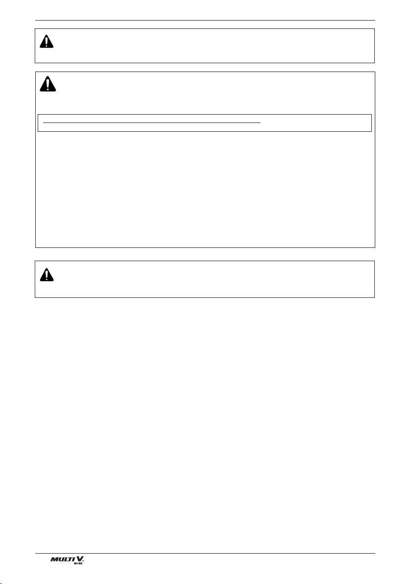
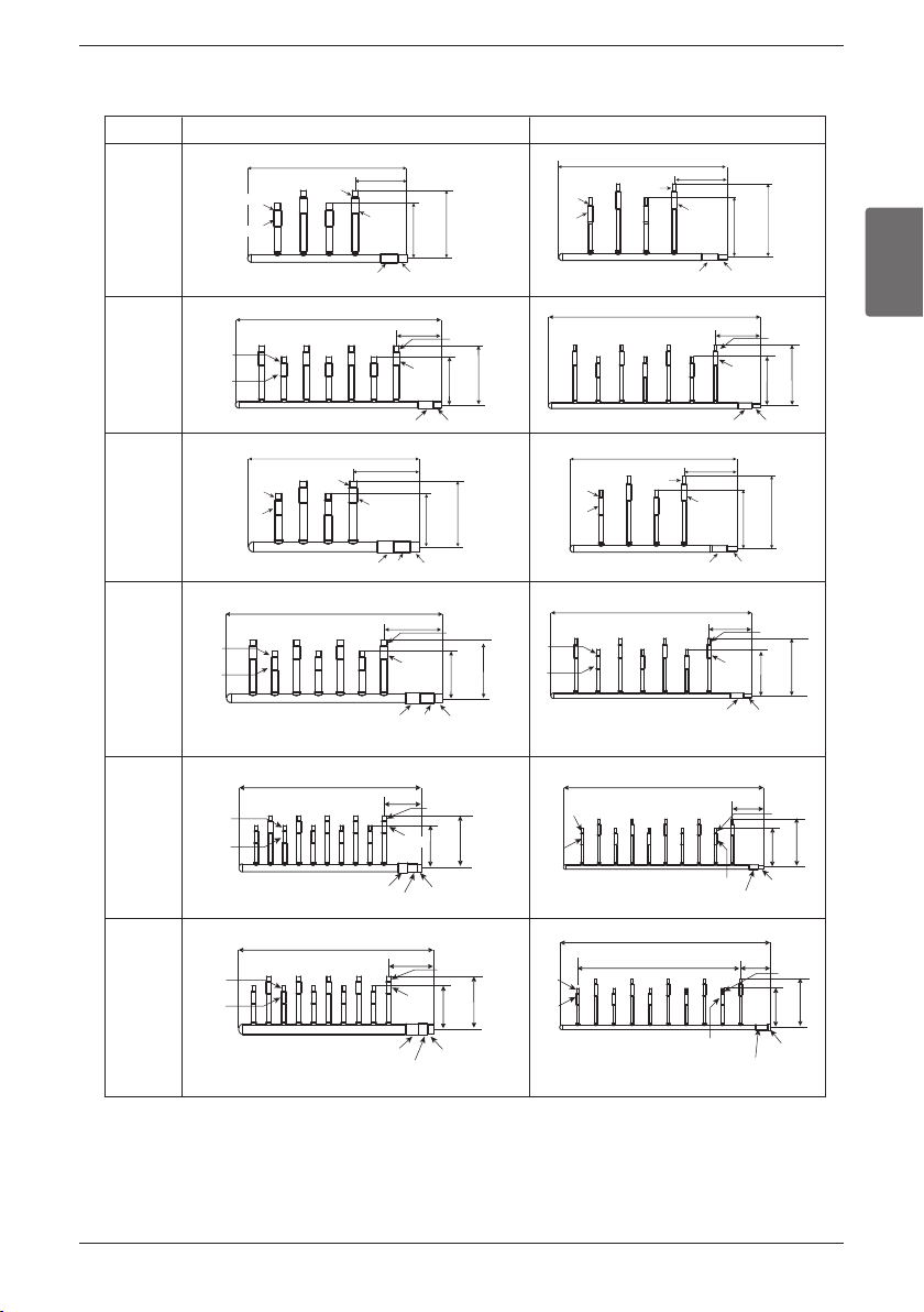
1. Line Distribution
2. Vertical Distribution
Ensure that the branch pipes are attached vertically.
3. The others
Header
1st
1st
1st
Main pipe
Distribution
2nd
2nd
3rd
2nd
Main pipe
Distribution
1st
3rd
3rd main pipe distribution
2nd
Distribution Method
Refrigerant Piping
32 Outside Unit
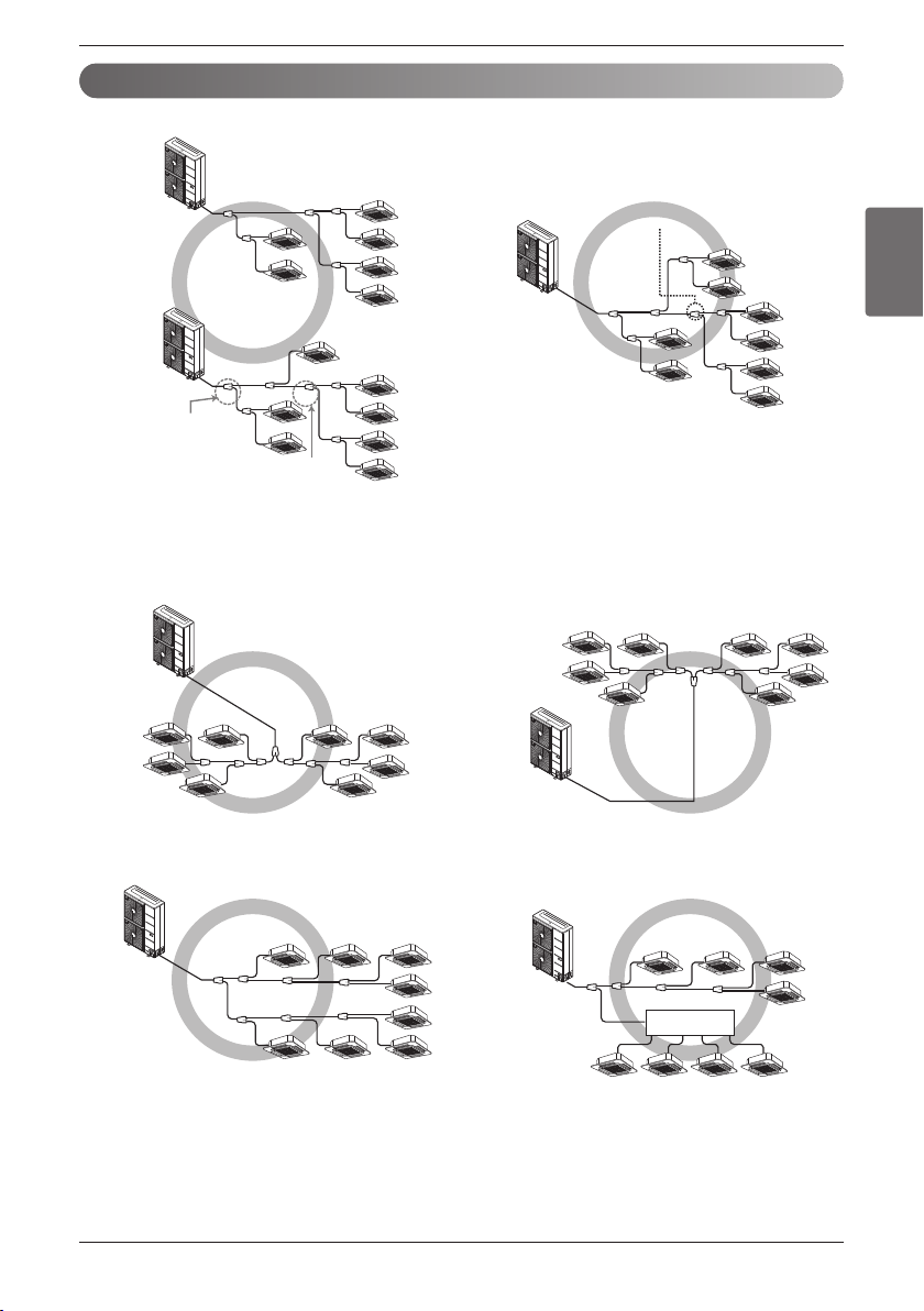
Branch Pipe Fitting
Y branch
A
B
To Outdoor Unit
To Branch Piping or Indoor Unit
A
B
Facing
upwards
Facing
downwards
Within ± 3° Within ± 3°
Viewed from point A
in direction of arrow
Horizontal
plane
Within +/- 10°
A
A
B
Header
To outdoor unit
To indoor unit
A
B
C
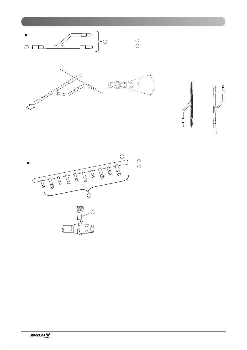
• Ensure that the branch pipes are attached horizontally or vertically (see the diagram below.)
• When the number of pipes to be connected is
smaller than the number of header branches,
install a cap to the unconnected branches.
• The indoor unit having larger capacity must be
installed closer to Ⓐ than smaller one.
• If the diameter of the refrigerant piping selected
by the procedures described is different from
the size of the joint,
the connecting section
should be cut with a pipe cutter.
ⓒ Pipe cutter
Refrigerant Piping
ENGLISH
Installation Manual 33
• When the number of indoor units to be connected to the branch pipes is less than the number of branch
pipes available for connection then cap pipes should be fitted to the surplus branches.
• Fit branch pipe lie in a horizontal plane.
• Header should be insulated with the insulator in each kit.
• Joints between branch and pipe should be sealed with the tape included in each kit.
• Any cap pipe should be insulated using the insulator provided with each kit and then taped as described
above.
B
Pinched pipe
Horizontal plane
View from point B in the direction of the arrow
Insulate the header using
the insulation
material attached to the
branch pipe kit
as shown in the figure.
Insulator
Insulator of field pipe
Tape
Tape
Cap pipe
Insulator for cap pipe
34 Outside Unit
Refrigerant Piping
1. Y Branch
Selection of Y Branch and Header
Models Gas pipe Liquid pipe
For example. Indicated Ø9.52 is the outer diameter(O.D..) of field jointed piping
[unit:mm]
ARBLN03321
ARBLN07121
ARBLN14521
ARBLN01621
I.D9.52(3/8)
I.D9.52(3/8)
O.D12.7(1/2)
I.D15.88
(5/8)
I.D19.05(3/4)
I.D12.7(1/2)
I.D12.7(1/2)
I.D19.05(3/4)
I.D15.88(5/8)I.D12.7(1/2)
I.D19.05(3/4)
O.D12.7(1/2)
I.D6.35(1/4)
I.D15.88(5/8)
I.D25.4(1)
413
390
83
I.D12.7(1/2)
O.D9.52(3/8)
I.D6.35(1/4)
I.D9.52(3/8)
I.D.9.52(3/8)
I.D.6.35(1/4)
I.D9.52(3/8)
I.D.6.35(1/4)
I.D19.05
(3/4)
O.D15.88(5/8)
I.D12.7(1/2)
I.D15.88(5/8)
I.D12.7(1/2)
I.D15.88(5/8)
I.D15.88(5/8)
I.D12.7(1/2)
292
281
292
281
74
74
7070
I.D15.88(5/8)
I.D19.05(3/4)
I.D12.7
(1/2)
I.D12. 7(1/2)
I.D19.05(3/4)
I.D15.88(5/8)I.D19.05(3/4)I.D22.2(7/8)
I.D28.58
(1-1/8)
O.D25.4(1)
I.D22.2(7/8)
O.D19.05(3/4)
O.D19.05
(3/4)
I.D22.2(7/8)
I.D25.4(1)
70 80 11 0
I.D12.7(1/2)
I.D6.35(1/4)I.D9.52 I.D9.52
I.D9.52
I.D12.7(1/2)
I.D6.35
(1/4)
I.D12.7(1/2)
332
321
74
376
404
96
471
517
125
416
444
96
371
394
83
I.D34.9
(1-3/8)
O.D31.8
(1-1/4)
I.D22.2
(7/8)
O.D22.2
(7/8)
I.D28.58
(1-1/8)
I.D31.8
(1-1/4)
O.D19.05
(3/4)
I.D28.58(1-1/8)
120 90
120 130
120 11 0 70
O.D15.88(5/8)
I.D9.52(3/8)
I.D12.7(1/2)
O.D12.7(1/2)
I.D6.35(1/4)
I.D9.52(3/8)
I.D15.88(5/8) I.D19.05(3/4)
I.D22.2(7/8)
I.D22.2(7/8)
I.D19.05(3/4)
I.D15.88(5/8)
I.D12.7
(1/2)
I.D15.88(5/8)
I.D19.05(3/4)
I.D22.2(7/8)
O.D19.05(3/4)
I.D19.05(3/4)
I.D15.88(5/8)
I.D12.7(1/2)
I.D19.05(3/4)
I.D22.2(7/8)
I.D41.3
I.D38.1(1-1/2)
I.D41.3
O.D34.9
(1-3/8)
I.D34.9(1-3/8)
I.D34.9(1-3/8)
I.D22.2
(7/8)
I.D28.58(1-1/8)
I.D28.58(1-1/8)
I.D38.1(1-1/2)
I.D41.3
I.D34.9
(1-3/8)
I.D38.1(1-1/2)
O.D22.2
(7/8)
O.D38.1(1-1/2)
O.D15.88(5/8)
O.D28.58(1-1/8)
90
80
11 0 11 0
I.D31.8(1-1/4)
I.D22.2(7/8)
I.D28.58(1-1/8)
I.D19.05(3/4)
I.D15.88(5/8)
I.D12.7
(1/2)
I.D19.05(3/4)
I.D15.88
(5/8)
1
1
2
2
2
3
3
3
2
2
3
2
3
3
2
3
3
3
1
2
1 3
3
1
2 3 3
2
1 2
1
ENGLISH
Installation Manual 35
Refrigerant Piping
2. Header
[Unit:mm(inch)]
4 branch
ARBL054
7 branch
ARBL057
4 branch
ARBL104
7 branch
ARBL107
10 branch
ARBL1010
10 branch
ARBL2010
Models Gas pipe Liquid pipe
360(14-5/32)
540(21-1/4)
540(21-1/4)
120(4-23/32)
ID15.88(5/8)
ID12.7(1/2)
ID12.7(1/2)
ID15.88(5/8)
ID15.88(5/8)
ID19.05(3/4)
120(4-23/32)
360(14-5/32)
ID9.52(3/8)
ID9.52(3/8)
ID6.35(1/4)
ID6.35(1/4)
ID9.52(3/8)
ID12.7(1/2)
150
(5-29/32)
150
(5-29/32)
150
(5-29/32)
150
(5-29/32)
150
(5-29/32)
400(15-23/32)
160(6-5/16)
ID15.88(5/8)ID15.88(5/8)
ID12.7(1/2)ID12.7(1/2)
ID15.88(5/8)
ID12.7(1/2)
ID19.05(3/4)
ID15.88(5/8)
ID22.2(7/8)
ID28.58(1-1/8)
ID25.4(1)
120
(4-23/32)
120
(4-23/32)
120
(4-23/32)
120
(4-23/32)
120
(4-23/32)
120
(4-23/32)
120
(4-23/32)
120
(4-23/32)
120
(4-23/32)
120(4-23/32)
ID15.88(5/8)
ID12.7(1/2)
ID15.88(5/8)
ID12.7(1/2)
ID15.88(5/8)
ID19.05(3/4)
120(4-23/32)
ID6.35(1/4)
ID9.52(3/8)
ID9.52(3/8)
ID12.7(1/2)
160(6-5/16)
580(22-27/32)
ID19.05(3/4)
ID15.88(5/8)
ID15.88(5/8)ID15.88(5/8)
ID12.7(1/2)ID12.7(1/2)
ID15.88(5/8)
ID12.7(1/2)
ID22.2(7/8)
ID28.58(1-1/8)
ID25.4(1)
700(27-9/16)
120(4-23/32)
ID6.35(1/4)
ID9.52(3/8)
ID9.52(3/8)ID9.52(3/8)
ID6.35(1/4)ID6.35(1/4)
ID9.52(3/8)
ID6.35(1/4)
ID9.52(3/8)ID12.7(1/2)
ID15.88(5/8)
ID12.7(1/2)
120(4-23/32)
720(28-11/32)
ID6.35(1/4)
ID9.52(3/8)
ID9.52(3/8)
ID6.35(1/4)
ID12.7(1/2)
ID9.52(3/8)
107(4-7/32)
60*9=540(21-1/2)
700(27-9/16)
ID6.35(1/4)
ID9.52(3/8)
ID19.05(3/4)
ID15.88(5/8)
ID9.52(3/8)
ID6.35(1/4)
ID9.52(3/8)
ID6.35(1/4)
120
(4-23/32)
120
(4-23/32)
160(6-5/16)
760(29-28/32)
ID19.05(3/4)
ID15.88(5/8)
ID22.2(7/8)
ID28.58(1-1/8)
ID25.4(1)
182(7-5/32)
775(30-17/32)
ID19.05(3/4)
ID15.88(5/8)
ID15.88(5/8)
ID12.7(1/2)
ID28.58(1-1/8)
ID31.8(1-1/4)
ID34.9(1-3/8)
150
(5-29/32)
150
(5-29/32)
150
(5-29/32)
150
(5-29/32)
150
(5-29/32)
150
(5-29/32)
150
(5-29/32)
120(4-23/32)
120
(4-23/32)
360(14-5/32)
ID9.52(3/8)
ID9.52(3/8)
ID6.35(1/4)
ID6.35(1/4)
ID9.52(3/8)
ID12.7(1/2)
36 Outside Unit
Refrigerant Piping
Thermal Insulation of Refrigerant Piping
Heat
insulation
material
Outer
covering
Adhesive + Heat - resistant polyethylene foam +
Adhesive tape
Indoor Vinyl tape
Floor exposed
Water-proof hemp cloth + Bronze asphalt
Outdoor
Water-proof hemp cloth + Zinc plate + Oily paint
Note:
When using polyethylene cover as covering material, asphalt roof-
ing shall not be required.
• Do not insulate gas or low pressure pipe and liquid or high
pressure pipe together.
• Be sure to fully insulate connecting portion.
Liquid pipe
Gas pipe
Power lines
Finishing tape
Insulating material
Bad example
Good example
These parts are not insulated.
B A C
A
B
C
A
C
D
E
A
B
C
D
E
Communication lines
F
Liquid pipe
Communication lines
Communication lines
Separation
Gas pipe
Power lines
Insulating material
A
B
C
D
E
A
A
B
F
Heat insulation material
Pipe
Outer covering
(Wind the connection part and cutting part of
heat insulation material with a finishing tape.)
Power lines
E
D
D
B
A
C
Be sure to give insulation work to refrigerant piping by covering liquid pipe and gas pipe separately with
enough thickness heat-resistant polyethylene, so that no gap is observed in the joint between indoor unit and
insulating material, and insulating materials themselves. When insulation work is insufficient, there is a possi-
bility of condensation drip, etc. Pay special attention to insulation work to ceiling plenum.
1m1m
A
B
D
F
F
G
B
G
D
B
H
I
J
A
E
B
I
A
B
D
C
Inner wall (concealed)
Floor (fireproofing)
Penetrating portion on fire
limit and boundary wall
Roof pipe shaft
Outer wall Outer wall (exposed)
Penetrations
Sleeve
Heat insulating material
Lagging
Caulking material
Band
Waterproofing layer
Sleeve with edge
Lagging material
Mortar or other incombustible caulking
Incombustible heat insulation material
When filling a gap with mortar, cover the
penetration part with steel plate so that
the insulation material will not be caved in.
For this part, use incombustible materials
for both insulation and covering.(Vinyl
covering should not be used.)
ENGLISH
Installation Manual 37
Refrigerant Piping
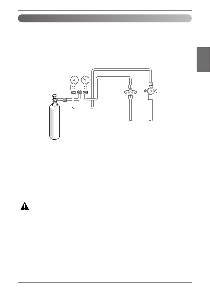
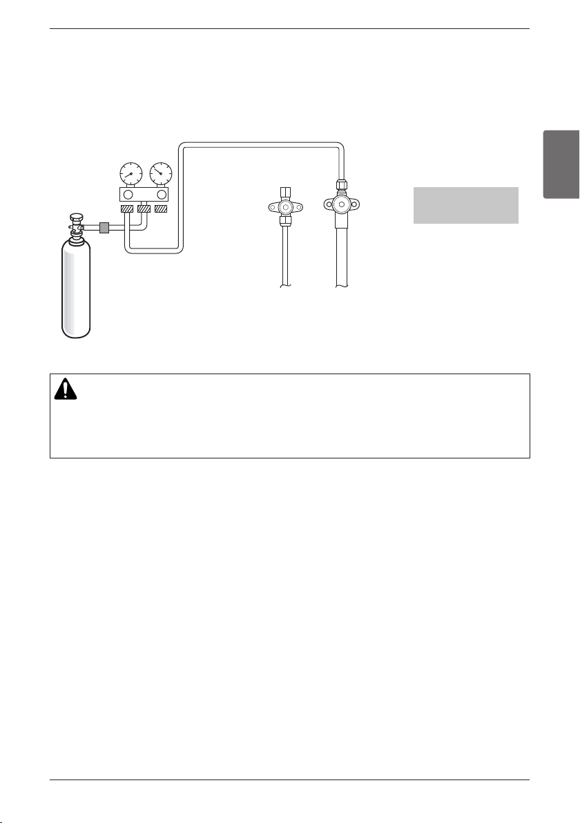
CAUTION
To prevent the nitrogen from entering the refrigeration system in the liquid state, the top of the cylinder must
be at higher position than the bottom when you pressurize the system.
Usually the cylinder is used in a vertical standing position.
Leak Test and Vacuum Drying
Nitrogen gas
cylinder
Liquide pipe
Gas pipe
1. Leak test
Leak test should be m
ade by pressurizing nitrogen gas to 38.7 kgf/cm
2
(551 psi). If the pressure does not drop
for 24 hours, the system passes the test. If the pressure drops, check where the nitrogen leaks. For the test
method, refer to the following figure. (Make a test with the service valves closed. Be also sure to pressurize liquid
pipe, gas pipe and high/low pressure common pipe)
The test result can be judged good if the pressure has not be reduced after leaving for about one day after com-
pletion of nitrogen gas pressurization.
During this test, set DIP switch as Vacuum Mode.
Note:
If the ambient temperature differs between the time when pressure is applied and when the pressure drop is
checked, apply the following correction factor
There is a pressure change of approximately 0.1 kgf/cm
2
(1.4 psi) for each 1°C(2°F) of temperature difference.
Correction= (Temp. at the time of pressurization – Temp. at the time of check) X 0.1
For example: Temperature at the time of pressurization (38.7 kgf/cm
2
(551 psi)) is 27°C(81°F)
24 hour later: (38.0 kgf/cm
2
(541 psi)) is 20°C(68°F)
In this case the pressure drop of 0.07 is because of temperature drop
And hence there is no leakage in pipe occurred.
38 Outside Unit
Refrigerant Piping
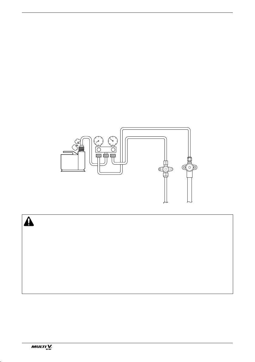
2. Vacuum
Vacuum drying should be made from the service port provided on the outdoor unit’s service valve to the vac-
uum pump commonly used for liquid pipe, gas pipe. Vaccum of the pipe and the indoor units should be
made from the port of the outdoor unit's service valve with the service valve closed.
* Never perform air purging using refrigerant.
• Vacuum drying: Use a vacuum pump that can evacuate to -100.7 kPa (5 Torr, -755mmHq).
1) Evacuate the system from the liquid and gas pipes with a vacuum pump for over 2 hrs and bring the sys-
tem to -100.7 kPa (5 Torr, -755mmHq).
After maintaining system under that condition for over 1 hr, confirm the vacuum gauge rises. The system
may contain moisture or leak.
2) Following should be executed if there is a possibility of moisture remaining inside the pipe.
(Rainwater may enter the pipe during work in the rainy season or over a long period of time)
After evacuating the system for 2 hrs, give pressure to the system to 0.5 kgf/cm
2
( 7.3 psi) (vacuum break)
with nitrogen gas and then evacuate it again with the vacuum pump for 1hr to -100.7 kPa (vacuum dry-
ing). If the system cannot be evacuated to -100.7kPa within 2 hrs, repeat the steps of vacuum break and
its drying.
Finally, check if the vacuum gauge does not rise or not, after maintaining the system in vacuum for 1 hr.
WARNING
• If the primary charging is not performed after vacuum, wet air may go into the outdoor unit. If air is mixed with the
refrigerant, the refrigerant cycle may malfunction and the unit may be damaged.
• Charging of refrigerant while the compressor is working is prohibited. Otherwise, liquid may go into the compres-
sor. It may cause faults of the compressor.
• Use a gravimeter accurate to 0.1kg.
• If other refrigerants are mixed in the original refrigerant, a refrigerant cycle may cause malfunction or damage.
• Add accurate refrigerant quantity via calculation.
Too much or too little refrigerant may cause problems
• Repeated on and off of the indoor units without charging refrigerant may cause faults of EEV.
• Since R410A is a mixed refrigerant, the required additional refrigerant must be charged in its liquid state. If the
refrigerant is charged in its gaseous state, its composition changes and the system will not work properly.
Vacuum pump
Liquide pipe
Gas pipe
ENGLISH
Installation Manual 39
Refrigerant Piping
CAUTION
Never charge the refrigerant with service valves closed and unit stopped.
If charging is carried out with service valves closed and unit stopped, the compressor will be damaged when unit
starts to run, and the unit will display ch26 error.
If trying to keep running under this condition, compressor will be broken.
3. Refrigerant charging
Follow following procedure to charge the refrigerant.
1. Open all service valves
2. Run the unit with cooling mode
3. Charging the refrigerant to gas service valve during operation.
Refrigerant
cylinder
Open Open
Charging during
cooling operation
Liquide pipe
Gas pipe
40 Outside Unit
Electrical Wiring
Electrical Wiring
CAUTION
Be sure to connect the Outdoor Unit to earth. Do not connect earth line to any gas pipe, water pipe,
lightening rod or telephone earth line. If earth is incomplete, it may cause an electric shock.
WARNING
Be sure to have authorized electrical engineers do the electric work using special circuits in
accordance with regulations and this installation manual. If power supply circuit has a lack of
capacity or electric work deficiency, it may cause an electric shock or fire.
1. Caution
1) Follow ordinance of your governmental organization for technical standard related to electrical equipment,
wiring regulations and guidance of each electric power company.
2) Install the Outdoor Unit communication line away from the power source wiring so that it is not affected by
electric noise from the power source. (Do not run it through the same conduit.)
3) Be sure to provide designated grounding work to Outdoor Unit.
4) Give some allowance to wiring for electrical part box of Indoor and Outdoor Units, because the box is some-
times removed at the time of service work.
5) Never connect the main power source to terminal block of communication line. If connected, electrical parts
will be burnt out.
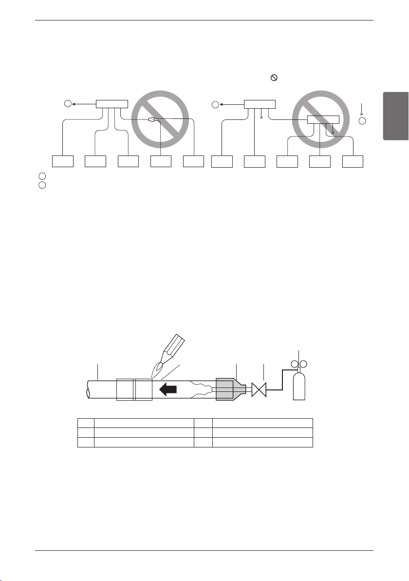
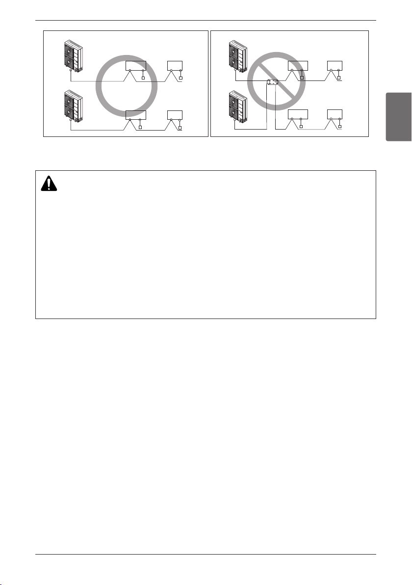
6) Use 2-core shield cable for communication line.(O mark in the figure below) If communication lines of differ-
ent systems are wired with the same multiplecore cable, the resultant poor transmitting and receiving will
cause erroneous operations. ( mark in the figure below)
7) Only the communication line specified should be connected to the terminal block for Outdoor Unit communi-
cation .
Electrical Wiring
ENGLISH
Installation Manual 41
Electrical Wiring
Remote
control
Remote
control
Remote
control
Remote
control
Indoor
Unit
Outdoor Unit
Outdoor Unit
Outdoor Unit
Outdoor Unit
Indoor
Unit
Remote
control
Remote
control
Indoor
Unit
Indoor
Unit
Remote
control
Remote
control
Indoor
Unit
Indoor
Unit
Indoor
Unit
Indoor
Unit
2-Core Shield Cable Multi-Core Cable
CAUTION
• This product have reversed phase protection detector that only works when the power is turned on.
If there exists black out or the power goes on and off which the product is operating, attach a
reversed phase protection circuit locally. running the product in reversed phase may break the com-
pressor and other parts.
• Use the 2-core shield cables for communication lines. Never use them together with power cables.
• The conductive shielding layer of cable should be grounded to the metal part of both units.
• Never use multi-core cable
• As this unit is equipped with an inverter, to install a phase leading capacitor not only will deteriorate
power factor improvement effect, but also may cause capacitor abnormal heating. Therefore, never
install a phase leading capacitor.
• Keep power imbalance within 2% of the supply rating. Large imbalance will shorten the life of the
smoothing capacitor.
• Introducing with a missing N-phase or with a mistaken N-phase will break the equipment.
42 Outside Unit
Electrical Wiring
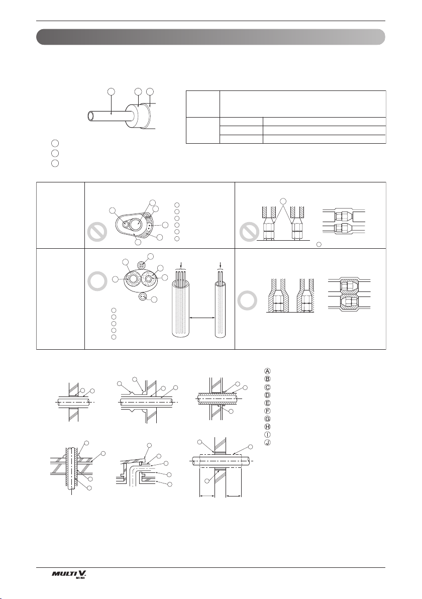
2. Communication and Power Lines
1) Communication cable
• Types : shielding wire CVVS or CPEVS
• Cross section : over 1.25mm
2
(0.002 in
2
)
• Insulation material : PVC
• Maximum allowable temperature: 60°C(140°F)
• Maximum allowable line length: 300m(984ft)
2) Remote control cable
• Types : 3-core cable
3) Simple central control cable
• Types : 4-core cable (Shielding wire)
• Cross section : over 0.75mm
2
(0.001 in
2
)
• Insulation material : PVC
4) Separation of communication and power lines
• If communication and power lines are run alongside each other then there is a strong likelihood of opera-
tional faults developing due to interference in the signal wiring caused by electrostatic and electromagnetic
coupling.
The tables below indicates our recommendation as to appropriate spacing of communication and power
lines where these are to be run side by side
Note:
1. The figures are based on assumed length of parallel cabling up to 100m(328ft). For length in excess of
100m the figures will have to be recalculated in direct proportion to the additional length of line involved.
2. If the power supply waveform continues to exhibit some distortion the recommended spacing in the
table should be increased.
• If the lines are laid inside conduits then the following point must also be taken into account when grouping
various lines together for introduction into the conduits
• Power lines(including power supply to air conditioner) and signal lines must not be laid inside the same
• In the same way, when grouping the lines power and signal lines should not be bunched together.
Current capacity of power line Spacing
10A 300mm(11-7/8inch)
50A 500mm(19-5/8inch)
100A 1000mm (39-1/4inch)
Exceed 100A 1500mm(59inch)
100V or more
CAUTION
• If apparatus is not properly earthed then there is always a risk of electric shocks, the earthing of the
apparatus must be carried out by a qualified person.
• Use a power wire pipe for the power wiring.

ENGLISH
Installation Manual 43
Electrical Wiring
Outdoor unit (1Ø, 208/230V, 60Hz), Indoor unit (1Ø, 208/230V, 60Hz)
1. Use a separate power supply for the Outdoor Unit and Indoor Unit.
2. Bear in mind ambient conditions (ambient temperature,direct sunlight, rain water,etc.) when proceed-
ing with the wiring and connections.
3. The wire size is the minimum value for metal conduit wiring. The power cord size should be 1 rank
thicker taking into account the line voltage drops. Make sure the power-supply voltage does not drop
more than 10%.
4. Specific wiring requirements should adhere to the wiring regulations of the region.
5. Power supply cords of parts of appliances for outdoor use should not be lighter than polychloroprene
sheathed flexible cord.
6. Don't install an individual switch or electrical outlet to disconnect each of indoor unit separately from
the power supply.
WARNING
• Follow ordinance of your governmental organization for technical standard related to electrical equipment, wiring reg-
ulations and guidance of each electric power company.
• Make sure to use specified wires for connections so that no external force is imparted to terminal connections. If con-
nections are not fixed firmly, it may cause heating or fire.
• Make sure to use the appropriate type of overcurrent protection switch. Note that generated overcurrent may include
some amount of direct current.
CAUTION
•
Some installation site may require attachment of an earth leakage breaker. If no earth leakage breaker is installed, it may
cause an electric shock.
•
Do not use anything other than breaker and fuse with correct capacity. Using fuse and wire or copper wire with too large
capacity may cause a malfunction of unit or fire.
Wiring of Main Power Supply and Equipment Capacity
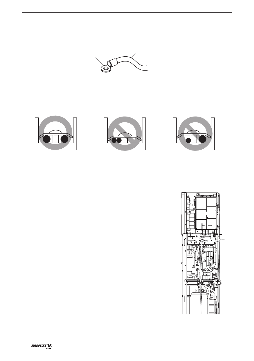
44 Outside Unit
Electrical Wiring
When none are available, follow the instructions below.
• Do not connect wiring of different thicknesses to the power terminal block. (Slack in the power wiring
may cause abnormal heat.)
• When connecting wiring which is the same thickness, do as shown in the figure below.
• For wiring, use the designated power wire and connect firmly, then secure to prevent outside pressure
being exerted on the terminal block.
• Use an appropriate screwdriver for tightening the terinal screws. A screwdriver with a small head will
strip the head and make proper tighterning impossible.
• Over-tightening the terminal screws may break them.
u Precautions when laying power and ground wiring
u How to connect wiring
1. Connect power supply wire to terminal block of control case
using clamps on the supporter and control case as shown figure
right.
2. Connect communication wire to main PCB terminal block using
clamps on the supporter and main PCB case as shown figure
right.
Round pressure terminal
Power wire(Ground wire)
Use round pressure terminals for connections to the power terminal block.
When laying ground wiring, you must use round pressure terminals.
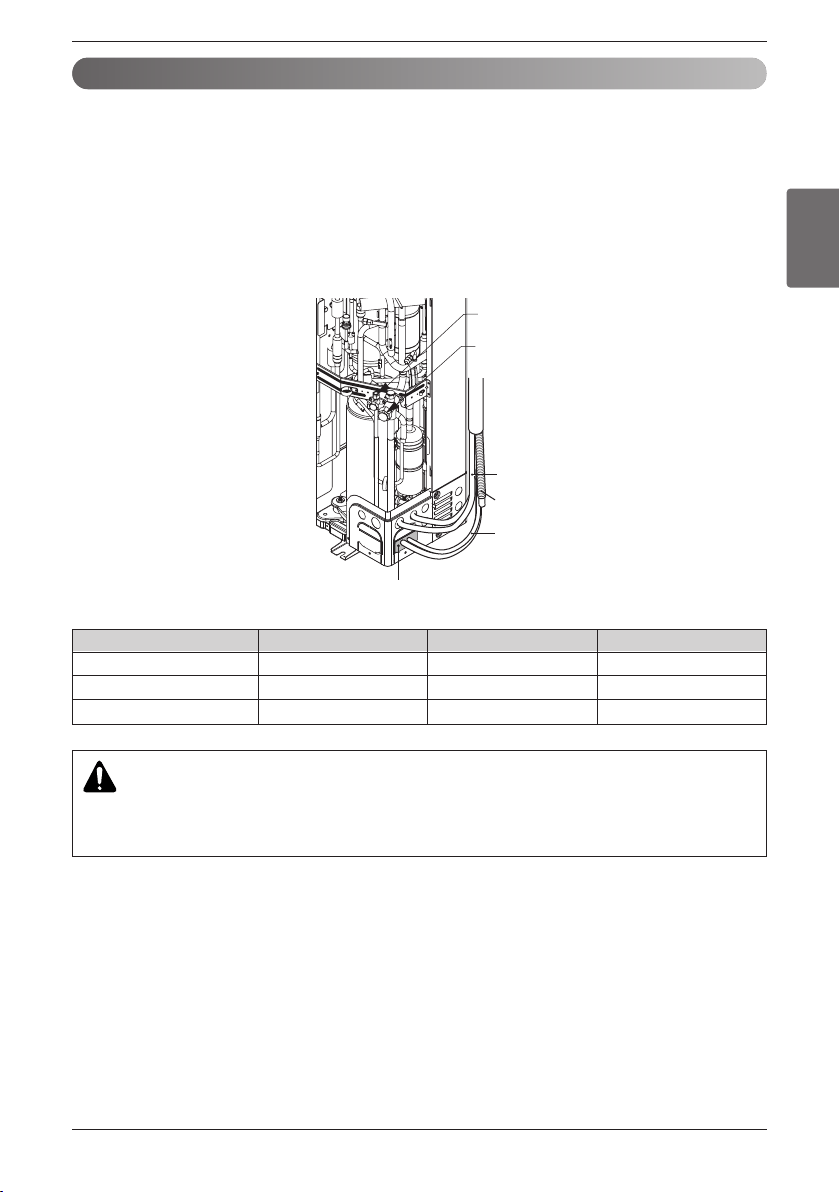
ENGLISH
Installation Manual 45
Electrical Wiring
Connection method of the connecting cable (Example)
1. Make a hole appropriate for the passage of connection cable through on cap by tool.
2. After knocking out the holes, we recommend you paint the edges and areas around the edges using
the repair paint to prevent rusting
3. Pass the connecting cable through the hole.
4. Properly connect the cable on the terminal block.
5. Fix the connection cable with the cord clamp providing on the unit not to have strain at the terminal.
6. Finally, Fix the cap to the conduit panel.
WARNING
• Loose wiring may cause the terminal to overheat or result in unit malfunction.
• A fire hazard may also exist.
• Therefore, be sure all wiring is tightly connected.
Gas side piping
(Bigger Dia.)
Liquid side piping
(Smaller Dia.)
Putty or insulating material
(produced locally)
Drain hose
Connecting wire
Connection pipe
Model name ARUN036GS2 ARUN047GS2 ARUN053GS2
AWG 8 8 8
Conduit (inch) 3/4 3/4 3/4
Knockout Diameter (inch) 1-3/32 1-3/32 1-3/32
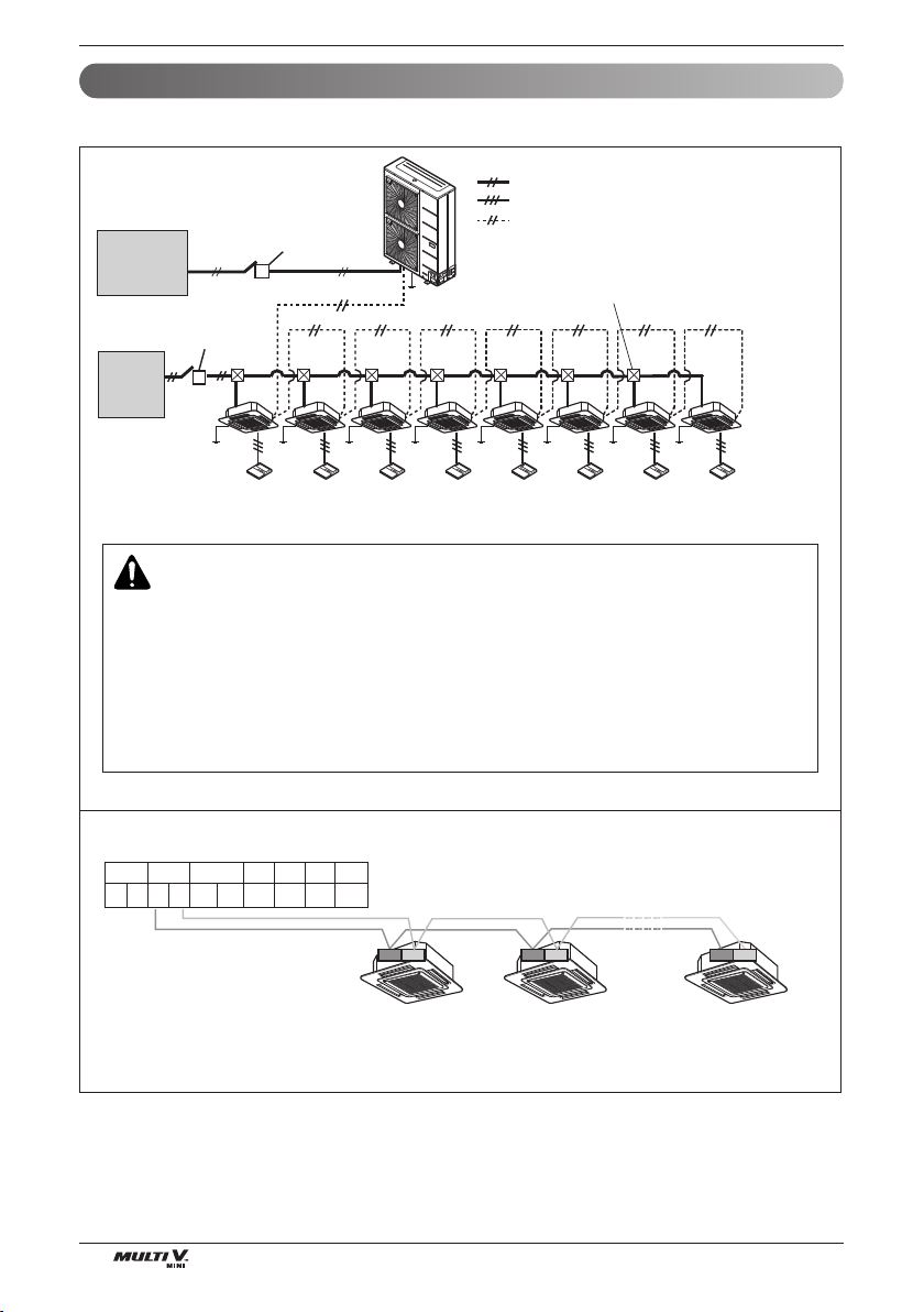
46 Outside Unit
Electrical Wiring
The GND terminal is a '–' terminal for the central controller, not Ground Line
Power supply switch
(Switch fuse : ELCB)
Power supply switch
(Switch fuse)
(Main Switch)
Pull Box(Installer Option)
: Single phase of power supply line(L, N)
: Communication line (3 line): Wired remote control
: Communication line (2 shield line):
Between Indoor Unit and Outdoor Unit
Single Phase 3wires
(L1,L2,GND)
Power supply
208/230V, 60Hz
Power supply
1 Phase
208/230V, 60Hz
3 4 34
Between Indoor and Outdoor unit (U3 Chassis, 2 Fan Model)
IDUSODU DRY1 DRY2 GND
INTERNET
BA
12V
BABA
34
1. 60Hz
WARNING
• Indoor Unit ground Lines are required for preventing electrical shock accident during current leakage,
Communication disorder by noise effect and motor current leakage (without connection to pipe).
• Don't install an individual switch or electrical outlet to disconnect each of indoor unit separately from the
power supply.
• Install the main switch that can interrupt all the power sources in an integrated manner because this system
consists of the equipment utilizing the multiple power sources.
• If there exists the possibility of reversed phase, lose phase, momentary blackout or the power goes on and off
while the product is operating, attach a reversed phase protection circuit locally.
Running the product in reversed phase may break the compressor and other parts.
Example Connection of Communication Cable
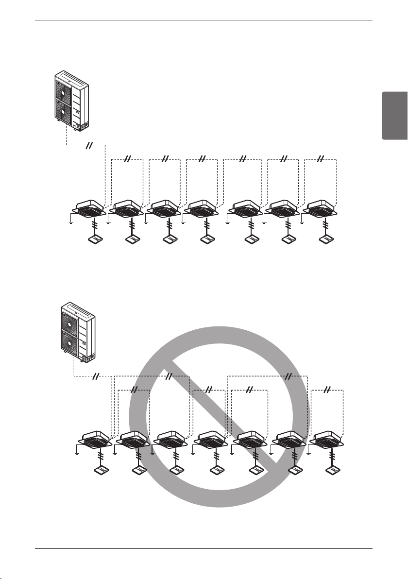
ENGLISH
Installation Manual 47
Electrical Wiring
n Example Connection of Communication Cable
[BUS type]
•
Connection of communication cable must be installed like below figure between indoor unit to outdoor unit.
[STAR type]
• Abnormal operation can be caused by communication defect, when connection of communication
cable is installed like below figure(STAR type).
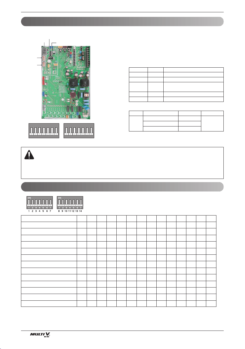
Electrical Wiring
48 Outside Unit
1234567891011121314
Short Pipe Length
Long Pipe Length
Refrigerant Auto Charging
Refrigerant Checking
Cool/Heat Selector
Snow (Heat Pump model)
Forced Defrosting (Heat Pump model)
Snow + Forced Defrosting (Heat Pump model)
Night Silent Operation
Pump Down
Pump Out (Heat Pump model)
Forced Oil Return
Vacuum Mode
l5
5l
ll l
ll l l
ll5
5l5
55l
5ll
ll
l5
ll
55 l
ll
Location of DIP Switch
Configuration of DIP Switch
SW01B
1234567
ON
SW02B
<Initial shipping condition of DIP Switch>
1234567
ON
Main PCB
SW01B
(DIP S/W)
SW02B
(DIP S/W)
7 - Segment
SW02V
Auto addressing
SW01V
Data confirm
SW01B SW02B
1.
When outdoor unit is powered on after configuring the DIP switch, prop-
er input of configuration value can be verified through 7-Segment.
2.
This function is shown only for 2 seconds after turning on the power.
n Verification of outdoor unit configuration
- After power is turned on, number are shown on
7-Segment consecutively
- These numbers show the configuration status
Model Code
In case of 1Φ, 5HP(48kBtu/h) model
Seqence NO. Content
1 121 Model code, 1~255
2 5 Total capacity (HP)
32
2 : heatpump
No display : cooling only
4 25 Normal
5 122 Model type, 1~255
WARNING
•
Main PCB power should be reset in order to recognize the changed function after handling the DIP switch for configuration of additional functions.
•
Main PCB power should be reset after resetting the DIP switch for cancellation of additional function
•
Please configure DIP switch properly. Otherwise, It can overstrain product during operation
4(36) 120
5(48) 121
6(53) 122
Phase Capacity(HP,kBtu/h) Model code Model type
1ø
122
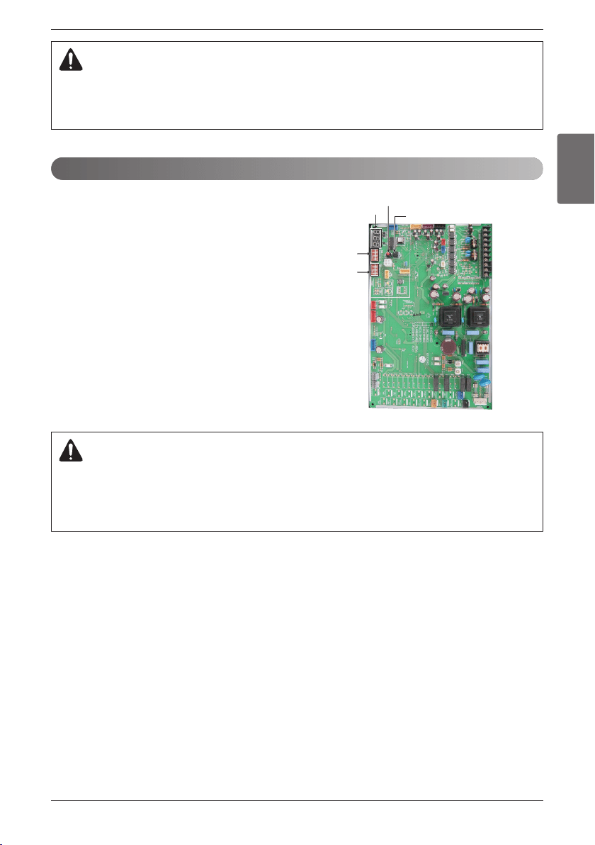
Electrical Wiring
ENGLISH
Installation Manual 49
CAUTION
1. “X” mark means DIP switch must be off, Otherwise the function may not perates correctly.
2. If each DIP switch doesn’t set correctly, unit will operate abnormally.
3. In case of proceeding test run, start after checking if all indoor unit is off.
SW01B
(DIP S/W)
SW02B
(DIP S/W)
7 - Segment
SW02V
Auto addressing
SW01V
Data confirm
• The address of indoor units would be set by auto
addressing
1) Wait for 3 minutes after applying power supply
(outdoor unit, indoor unit).
2) Press the switch of the outdoor unit (SW02V) for 5
seconds.
3) A "88" is indicated on 7-segment LED of the outdoor
unit PCB.
4) For completing addressing, 2~7 minutes are required
depending on numbers of indoor unit connection set.
5) Numbers of indoor unit connection set whose
addressing is completed are indicated for 30seconds
on 7-segment LED of the outdoor unit PCB.
6) After completing addressing, address of each indoor
unit is indicated on the wired remote control display
window. (CH01, CH02, CH03, ............. CH06:
Indicated as numbers of indoor unit connection set.)
CAUTION
In replacement of the indoor unit PCB, always perform auto address setting again.
- If power supply is not applied to the indoor unit, operation error occurs.
- Auto addressing is only possible on the main PCB
- Auto addressing has to be performed after 3 minutes to improve communication.
Automatic Addressing
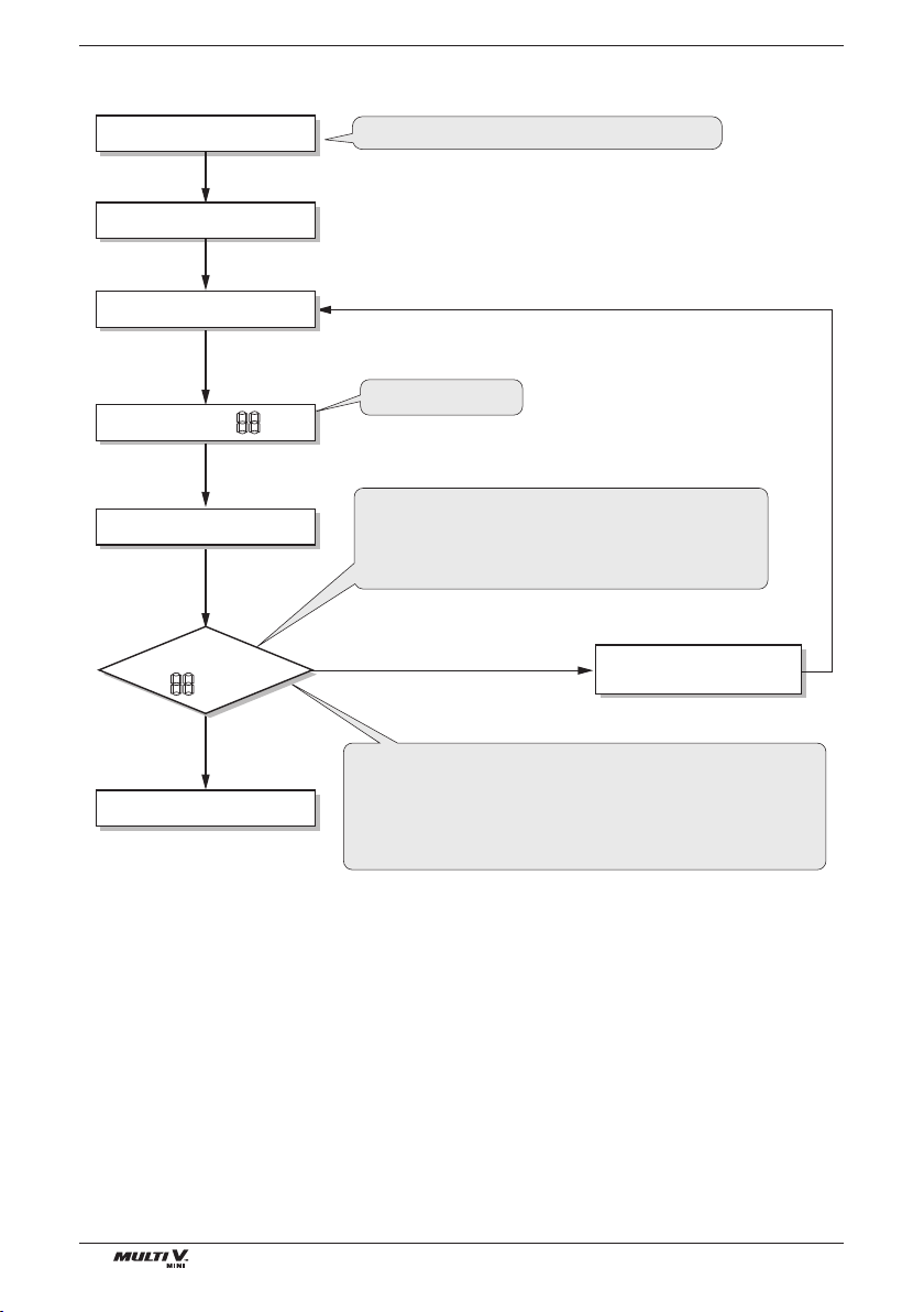
Electrical Wiring
50 Outside Unit
u The Procedure of Automatic Addressing
• Auto addressing setting end
Numbers of indoor unit connection set whose
addressing is completed are indicated for 30seconds
on 7-segment LED after completing setting
Indoor address number is displayed on wired remote control or
indoor unit display window. It is not an error message, will
disappeared when on/off button is pressed on remote control
ex) Display of 01, 02, ..., 15 means connection of 15 indoor
units and auto addressing is completed normally.
Auto addressing start
Waiting 3 minutes
Power On
Press SW02V for 5 sec.
7-segment LED = 88
Waiting about 2~7 minutes
7-segment LED
OK
YES
NO Check the connections
of communication line
= 88
All DIP switch should be off before auto adressing
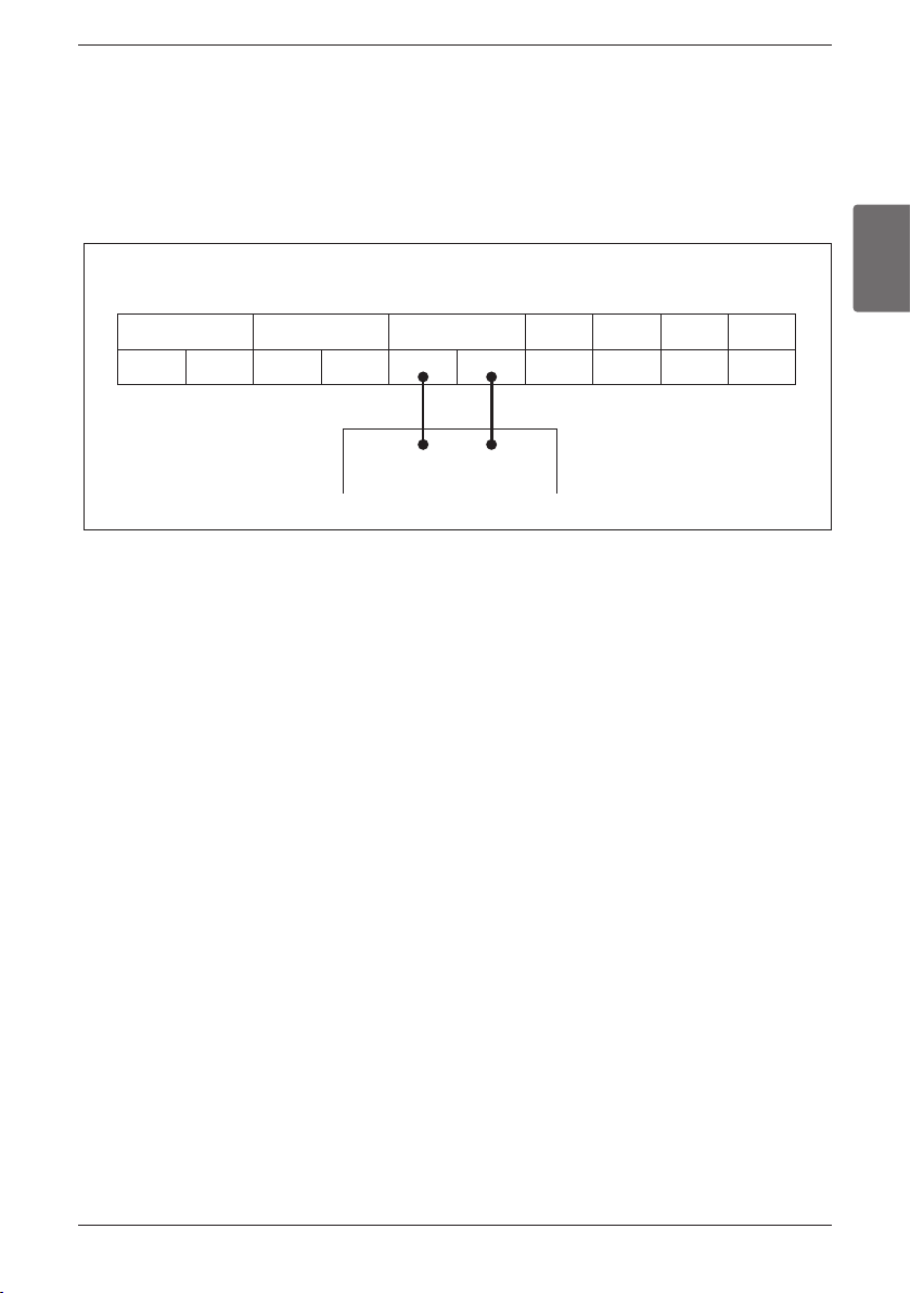
Electrical Wiring
ENGLISH
Installation Manual 51
u How to connect central controller (U3 Chassis, 2 Fan Model)
- The communication lines connected to INTERNET terminal should be connected to central control of Outdoor
unti with care for their polarity( A ’ A, B ’ B )
- Connect communication lines between outdoor unit and indoor units through the terminal block.
- When connecting communication line between outdoor unit and indoor units with shielded wire, connect the
shield ground to the earth screw.
- When connecting the central control system with shielded wire, connect the shield ground to the earth screw.
Terminal block on the main PCB
SODU IDU INTERNET DRY1 DRY2
B
A
B(D) A(C)
GND 12V
Outdoor Units
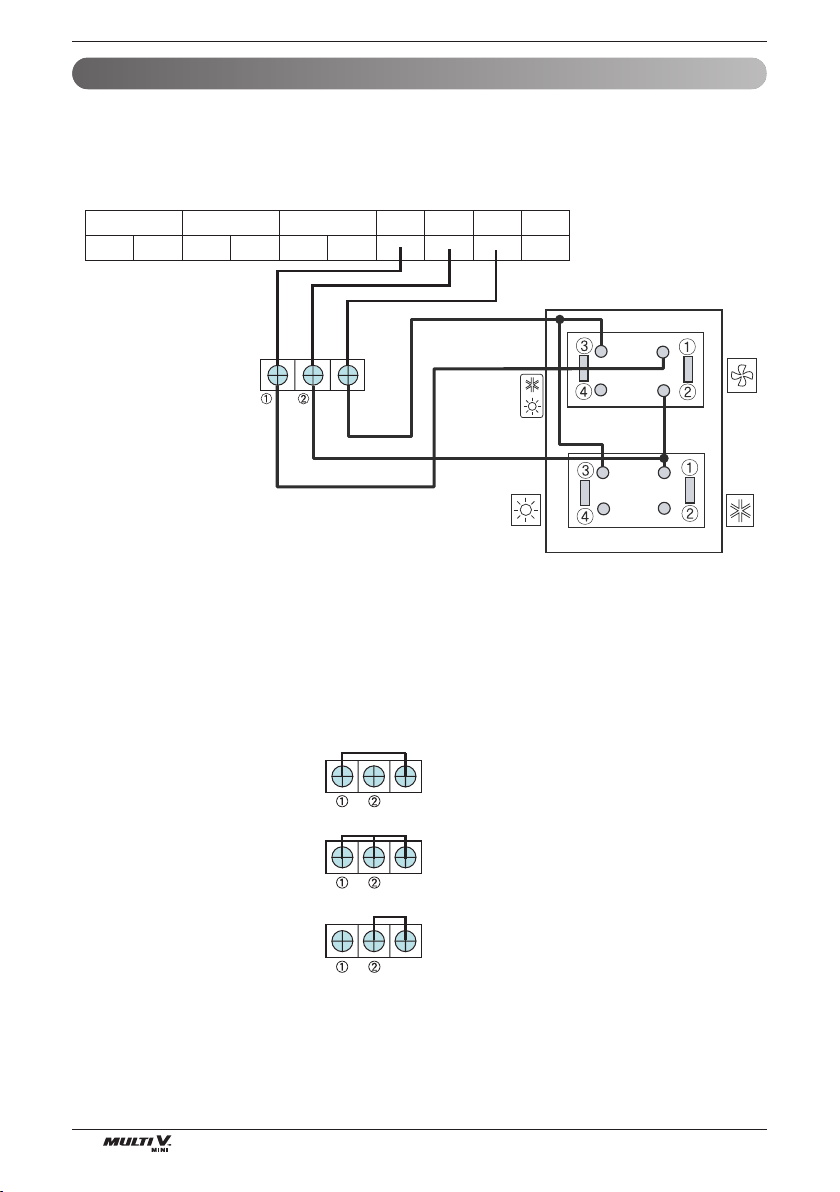
52 Outside Unit
Electrical Wiring
Cool/Heat Selector Installation and Connection(Heat pump only)
n Using Cool/Heat Selector Installation and Connection
• Connect wires as below figure at the hole of backside of Outdoor Unit Dry Contact.
• Insert the wire in the connection hole pushing the "Push" button.
• Setting Main PCB DIP SW of Master Outdoor Unit.
Mode Change
Push Button
Heating
Outdoor Unit
GND
GND
GND
Fan
Cooling
SODU IDU INTERNET DRY1 DRY2 GND 12V
GND
n Without Cool/Heat Selector Installation and Connection
In case, try to set mode without Cool/Heat Selector and try to use other switch except from LG Outdoor
Cool/Heat Selector in field.
Connect signal terminal block as below figure and description.
- How to set mode without Cool/Heat Selector
• Cooling Mode Setting
¿‘GND Connection
¡‘Off (Open)
• Heating Mode Setting
¿‘ GND Connection
¡‘GND Connection
• Fan Mode Setting
¿‘ Off (Open)
¡‘GND Connection

ENGLISH
Installation Manual 53
Test Run
1. Test run should be performed after auto-addressing
2.
Test run can be performed when 3 minutes passed after power on, by DIP switches and buttons. -
needs time for initializing data of micom and readying communication with indoor unit.
3. 7-segment of outdoor unit displays test run status and error.
4. During test run, if error occurs, then test run ends and proceeds final stage of test run - sys-
tem should be initial status by initializing all data of test run pressing black button for 2 seconds after
all DIP switch off
5. In case of finishing test run during test run, press black and red button simultaneously for 5
seconds.
6. When test run is finished, indoor units are stopped and 938 is displayed after 90 seconds.
7. To perform FDD logic test, proceeds when 3 minutes passed after reset.
Step 0. Check order signal
Select the function of tust run
Step 1. Sensor checking
Check sensor abnormality.
Step 2. Refrigerant auto charging
In case of adding additional refrigerant, this function helps adding refrigerant automatically.
Step 3. Refrigerant checking
Check refrigerant amount is proper.
Test Run
Checks before Test Run
Test Run Procedure
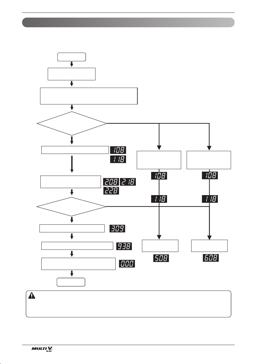
54 Outside Unit
Test Run
Sensor checking function judges whether the current temperature of indoor and outdoor unit sensors is right or
not. It checks 3 indoor temperature sensors, 9 outdoor temperature sensors, 2 outdoor pressure sensors.
It is used for judging sensor abnormality. Note 2)
Note 1)
Sensor Checking Function (U3 Chassis, 2Fan Model)
Wait for 3 min. after power
reset
Note 3)
Start
Main PCB
SW01S
Set the DIP S/W according to the function
Sensor Checking
➠
Refrigerant Auto Charging : 1,2,7 ON
Sensor Checking
➠
Refrigerant Checking : 1,2,7,14 ON
Main PCB
SW01B
SW02B
Press the black button for 2 sec. on main PCB.
Main PCB
SW01V
Indoor/Outdoor units operate with
air circulation mode
Refrigerant Auto Charging
Press the black button
until '508' is displayed
Judging sensor
normality
Error Display
Refrigerant
Auto Charging
Main pcb
LED
Note 4)
Press the black button on the main PCB for 2 sec.
Main PCB
SW01V
Press the black button for 2 sec. after turning off all
of DIP S/W.
Refrigerant Checking
Press the black button
until '608' is displayed.
Refrigerant
Checking
Don’t Perform Sensor Checking
No
Yes
Yes
No
Completed.
Note
1. Sensor checking function is used with Refrigerant
Checking and Refrigerant Auto Charging.
2. Check abnormal sensor
3.
It is displayed at the LED on the main PCB at each step.
4. Refer to the next page for sensor error code part
Would you perform
the Sensor
checking?
Caution
1. Confirm auto addressing has been performed (Check installed number of IDU).
2. The error can be displayed even if the sensor is normal according to installation and temperature condition.
If error occurs, check the sensor and judge abnormality.
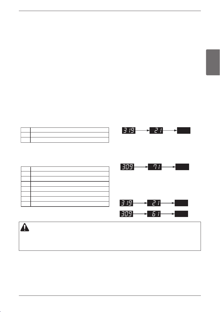
ENGLISH
Installation Manual 55
Test Run
■ Indoor unit error display
1. 1
st
and 2
nd
number represents indoor unit number.
Indoor unit number follows auto addressing number.
2. Last number represents sensor.
❈ Indoor unit number follows Auto addressing number.
■ Displaying outdoor unit error
1. 1
st
and 2
nd
number represents error content(code).
2. Last number represents outdoor unit number.
ex) Indoor unit No. 2 pipe inlet temperature sensor
error
ex) Outdoor unit liquid pipe temperature
sensor error
1 Outdoor Air Temperature
2 Heat Exchanger 1
4 Inverter Compressor Discharge Temperature
6 Suction Temperature
7 Liquid Pipe Temperature
9 SC pipe out
10 High Pressure Sensor
11 Low Pressure Sensor
ex) Indoor unit No.2 pipe inlet temperature sensor error and
outdoor unit suction temperature sensor error
1 Pipe inlet temperature sensor
2 Pipe outlet temperature sensor
3 Air temperature sensor
Error display during sensor inspection process is composed of 3 stages as shown below, and is proceeded by repeating
these stages
n Step 1 : Display of error existence : 309 or 319
- 309 : Inspect sensors of outdoor unit
- 319 : Inspect sensors of indoor unit
n Step 2: Display of error location
- In case of 309 (outdoor unit sensors)
2 digits on the left among 7 segments – Sensor Type (Table1)
1 digit on the right among 7 segments – Outdoor Unit Number
- In case of 319 (indoor unit sensors)
2 digits on the left among 7 segments – Indoor Unit Number
(Same as LGMV (automatic address configuration) indoor unit number)
1 Digit on the right among 7 segments – Sensor Type (Table 2)
n Step 3: Turn Off
h 1 error is displayed through 3 stages above and maximum of 5 errors are displayed.
Sensor Check Error Code Display
Displaying error content
CAUTION
1. Up to 5 number of errors is displayed continuously and repeatedly. In case 5 number of errors occurs, again perform
sensor checking after solving errors.
2. IDU in which error occurred operates air circulation mode.
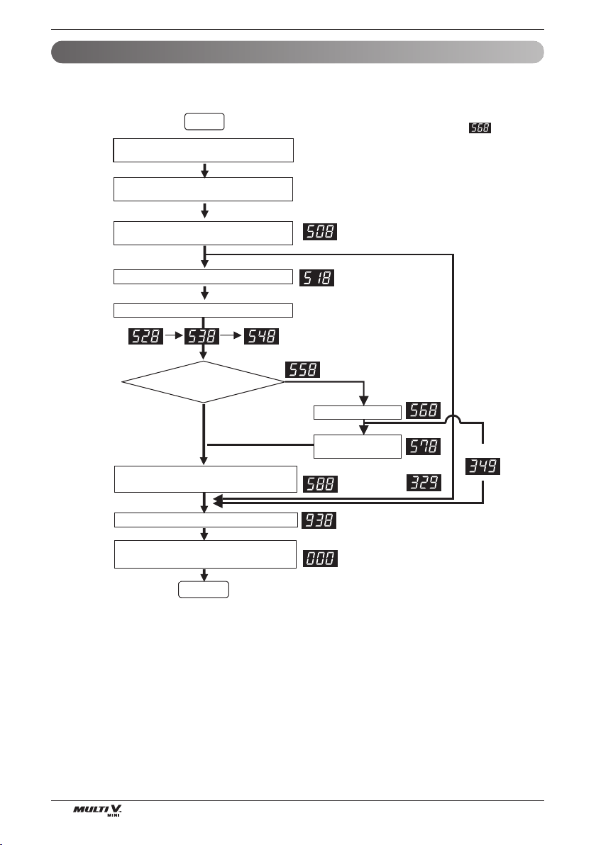
56 Outside Unit
Test Run
Refrigerant Auto Charging Function
This function charges appropriate amount of refrigerant automatically through cycle operation.
It can be used when refrigerant amount Isn't certain because of SVC and leakage.
Note
1.
After installing the refrigerant charging device
as shown below in figure, open the valve.
2.
In case air temperature is out of guaranteed temperature,
it may end without performing auto charging.
3. Refrigerant auto charging may over without using capillary
assembly by sudden inflow of liquid state refrigerant.
4.
Refrigerant Charging Time may change according to the
charging amount. (Refrigerant Charging Time : about 3 min./kg)
Wait for 3 min. after power reset
Start
Main PCB
SW01S
Set the DIP swtich.
Refrigerant Auto Changing : 1,2,7 ON
Main PCB
SW01B
SW02B
Press the black button on main PCB.
Is it necessary to
charge refrigerant?
Press the black button for 2 sec. after turning off
all of DIP swtich.
Yes
No
Press the black button on main PCB.
( Press until ‘508’ is displayed )
Main PCB
SW01V
IDU runs with cooling mode In designated order.
Main PCB
SW01V
Press the black button
IDU and ODU are turned off when Auto Charging
is completed. Close the valve.
Press the black button
Note 1)
Refrigerant Auto
Charging Process
Main PCB
SW01V
Completed.
Note 2)
Note 3)
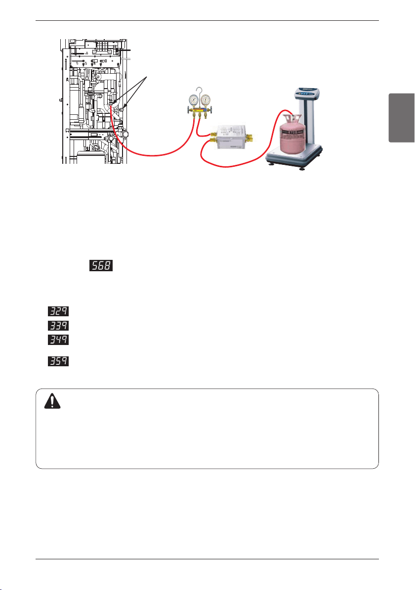
ENGLISH
Installation Manual 57
Test Run
Capillary Assembly
Charging
port
manifold
Procedure
1. Arrange manifold,capillary assembly, refrigerant vessel and scale
2. Connect manifold to the gas pipe service valve of ODU as shown in the figure.
3. Connect manifold and Capillary tube.
Use designated capillary assembly only.
If designated capillary assembly isn't used, the system may get damaged.
4. Connect capillary and refrigerant vessel.
5. Purge hose and manifold.
6. After Is displayed, open the valve and charge the refrigerant
CAUTION
1. Guaranteed temperature range (Error will occur if temperature is out of range)
IDU : 68~89.6°F
ODU : 32~109.4°F
2. For refrigerant charging, use designated device only. (Capillary Assem Set)
3. Set the IDU wired remote controller temperature sensing mode as IDU
4. Be careful that IDU should not be thermo off.
n Error contents about auto refrigerant charging function
1. : Temperature Range Error (In case that IDU or ODU is out of range)
2. : Low Pressure Descent Error (In case the system runs at low pressure limit for over 10 minutes)
3. : Judging rapid refrigerant inflow ( In case the liquid refrigerant flows in because of not using desig-
nated Capillary Assembly)
4. : Instability Error( In case the high/low pressure target doesn't get satisfied for some time
after the starting operation)
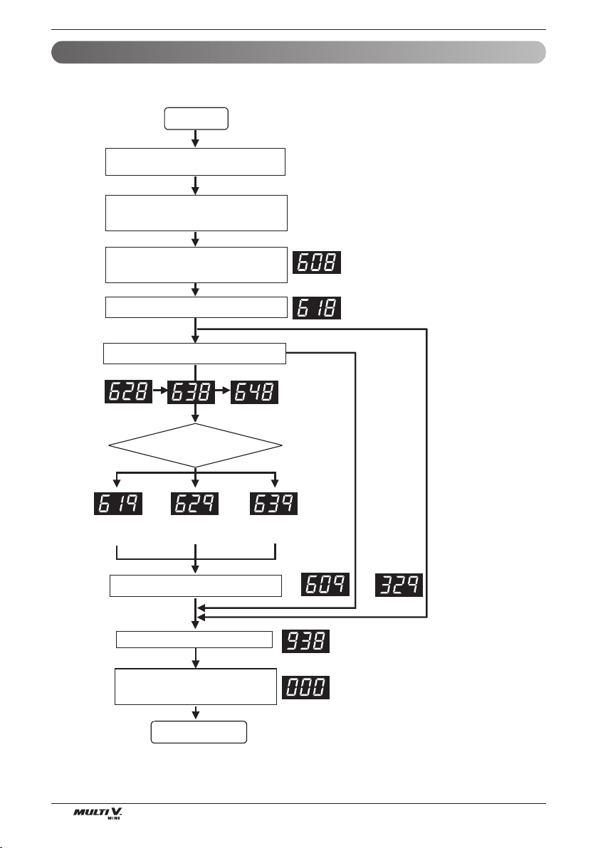
58 Outside Unit
Test Run
This function charges appropriate amount of refrigerant automatically through cycle operation.
This function judges refrigerant leakage and overcharging.
Refrigerant Checking Function
Wait for 3 min. after power reset
Start
Main
PCB
SW01S
Set the DIP S/W.
Refrigerant Checking : 1,2,7,14 ON
Main
PCB
SW01B
SW02B
Press the black button on main PCB
Press the black button for 2 sec. after
turning off all of DIP S/W.
Completed
Press the black button on main PCB.
( Press until ‘608’ is displayed )
Main
PCB
SW01V
IDU runs with cooling mode in order.
Main
PCB
SW01V
Press the black button on main PCB
Main
PCB
SW01V
Note 1)
IDU, ODU are turned off
Note 2)
Judging
Refrigerant
Amount
Note
1. In case air temperature is out of guaranteed
temperature, refrigerant checking function may end
without performing refrigerant checking. Use
guaranteed temperature range only.
2. During the process of judging refrigerant amount, if
the cycle isn't stable, refrigerant checking function
may end without performing refrigerant checking.
Excess of
Refrigerant
Scarcity of
Refrigerant
Impossible
To Judge
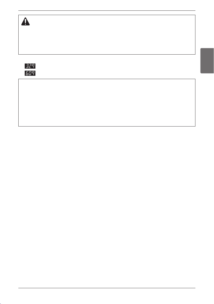
ENGLISH
Installation Manual 59
Test Run
[ Error contents about auto refrigerant charging function ]
1. : Temperature Range Error (In case that IDU or ODU is out of range)
2. : System Unstable Error (In case, After 45 min operating the system, it does not be stable)
How to cope with Result of Refrigerant Checking
1. If the temperature is not in guaranteed Temperature range, the system will not execute Refrigerant check-
ing and the system will be OFF.
2. Excess of Refrigerant(619)
After remove the 20% of calculated total refrigerant, recharge the refrigerant by using Refrigerant Auto
Charging Function.
3. Scarcity of Refrigerant(629)
Charge the refrigerant by using Refrigerant Auto Charging Function.
4. Impossible to Judge(639)
IF the system is not in order, check the other problem except refrigerant.
CAUTION
1. Guaranteed Temperature range(Error occurs out of guaranteed temperature range)
IDU : 68~89.6°F
ODU : 32~109.4°F
2. Set IDU wired remote controller temperature sensor setting as 'IDU'.
3. Make certain that IDU doesn't run with thermo off mode during operation.
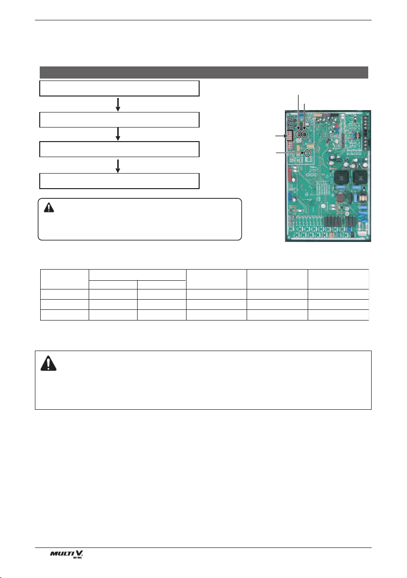
60 Outside Unit
Test Run
Night Silent Operation
In cooling mode, this function makes the ODU fan operate at low RPM to reduce the fan noise of ODU at night
which has low cooling load.
Caution
1. Request installer to set the function during installation.
2. In case the function is not used, set the DIP switch OFF and reset the power.
3. If ODU RPM changes, cooling capacity may go down.
Main PCB power reset
DIP switch No.12+14 ON
ODU
SW01S
ODU
SW01B
Setting complete
Setting the Fan Max. RPM
SW01V
SW02V
Note 1)
U3 Chassis (2 Fan Model)
Note
1.Setting RPM
1 time
1 time
1 time
SW02V (Red)
9
9
9
Operation
(hr)
8
8
8
420
370
320
1
2
3
Judgment
(hr)
Fan Max
RPM
Setting
Step
SW01V (Black)
1 time
2 times
3 times
SW01S
SW02V
SW01V
SW01B
※
Reset power after changing DIP S/W
CAUTION
1. Request additional function setting to installer.
2. In case of not using additional function, DIP switch off and reset.
3. If RPM of outdoor unit fan is changed, capacity may be down.
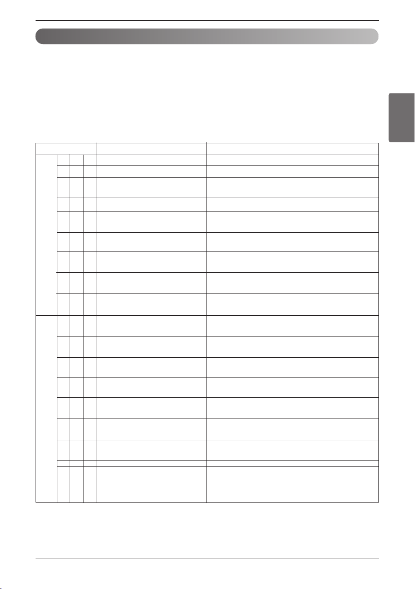
ENGLISH
Installation Manual 61
Test Run
Error Indicator
• This function indicates types of failure in self-diagnosis and occurrence of failure for air condition.
• Error mark is displayed on display window of indoor units and wired remote controller, and 7-segment LED of
outdoor unit control board as shown in the table.
• If more than two troubles occur simultaneously, lower number of error code is first displayed.
• After error occurrence, if error is released, error LED is also released simultaneously.
Error Display
1st,2nd LED of 7-segment indicates error number, 3rd LED indicates unit number.
※
Refer to the DX-Venitilation manual for DX-Venitilation error code.
Self-Diagnosis Function
Display Title Cause of Error
01-
02-
03-
04-
05-
06-
09-
10-
17-
211
221
231
241
251
261
271
281
291
Air temperature sensor of indoor unit
Inlet pipe temperature sensor of indoor unit
Communication error : wired
remote controller ÷ indoor unit
Drain pump
Communication error : outdoor
unit ÷ indoor unit
Outlet pipe temperature sensor of
indoor unit
Indoor EEPROM Error
Poor fan motor operation
Inlet Air temperature sensor of
FAU
Outdoor Unit Inverter Compressor
IPM Fault
Inverter Board Input Over
Current(RMS) of Outdoor Unit
Outdoor Unit Inverter Compressor
DC link Low Voltage
Outdoor Unit High Pressure
Switch
Outdoor Unit Input Voltage High/
Low Voltage
Outdoor Unit Inverter Compressor
Start Failure
PSC/PFC Fault error
Outdoor Unit Inverter DC link High
Voltage
Outdoor Unit Inverter Compressor
Over Current
Air temperature sensor of indoor unit is open or short
Inlet pipe temperature sensor of indoor unit is open or short
Failing to receive wired remote controller signal in
indoor unit PCB
Malfunction of drain pump
Failing to receive outdoor unit signal in indoor unit PCB
Outlet pipe temperature sensor of indoor unit is
open or short
In case when the serial number marked on
EEPROM of Indoor unit is 0 or FFFFFF
Disconnecting the fan motor connector/Failure of indoor fan
motor lock
Air temperature sensor of indoor unit is open or short
Outdoor Unit Inverter Compressor Drive IPM Fault
Outdoor Unit Inverter Board Input Current excess
(RMS)
DC charging is not performed at outdoor unit after
starting relay turn on.
System is turned off by outdoor unit high pressure
switch.
Outdoor Unit input voltage is out of range.
The First Start Failure by Outdoor Unit Inverter
Compressor Abnormality
When over current flows instantly at PSC/PFC
System is turned off by outdoor unit DC Voltage Over
Charging
Outdoor Unit Inverter Compressor Fault OR Drive
Fault
Indoor unit related error
Outdoor unit related error
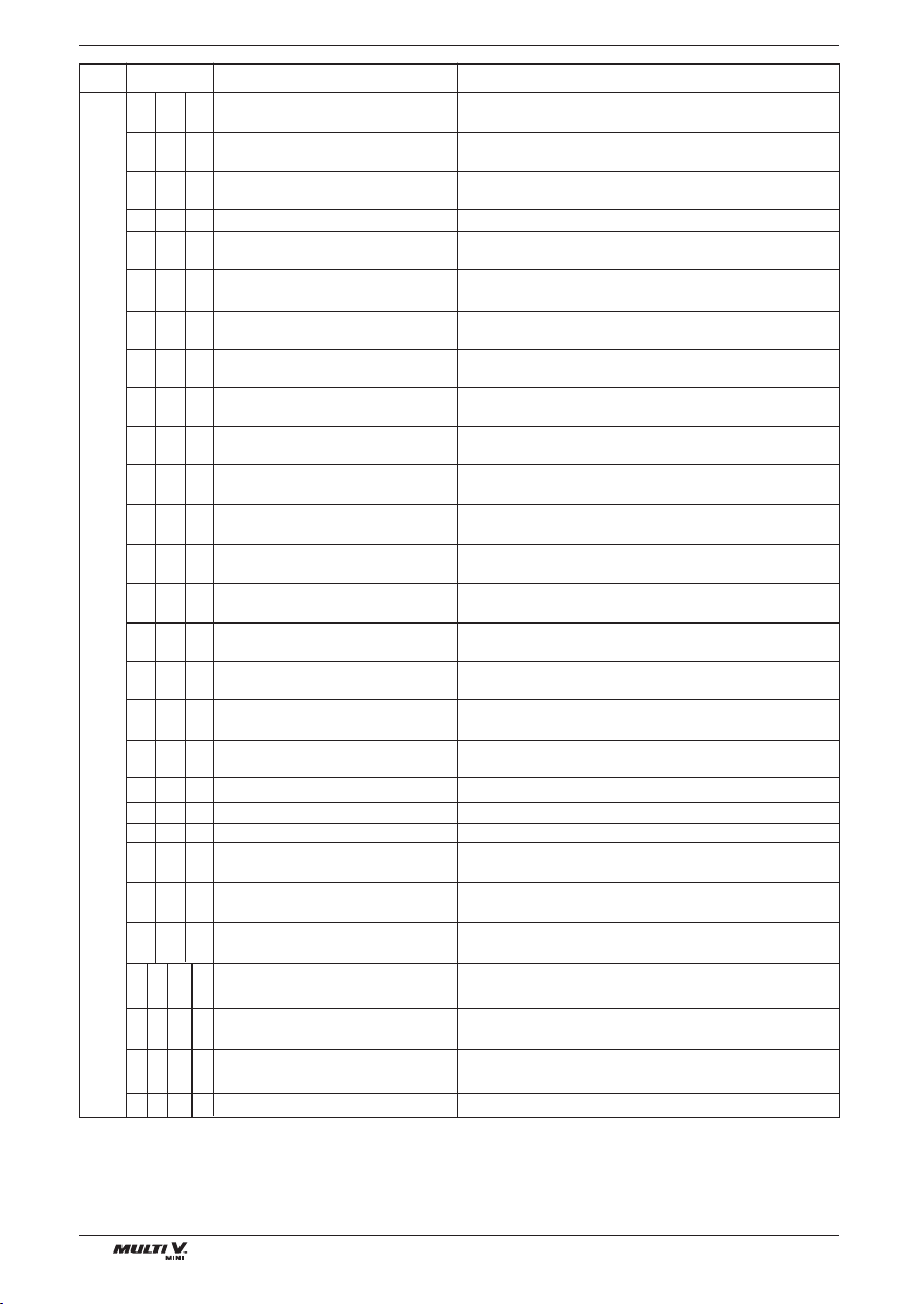
62 Outside Unit
Test Run
System is turned off by outdoor unit Inverter
Compressor High Discharge Temperature
System is turned off by excessive increase of high
pressure of outdoor unit
System is turned off by excessive decrease of low
pressure of outdoor unit
Pressure ratio is under limit
Outdoor Unit Inverter Compressor CT Sensor open or
short
Outdoor Unit Inverter Compressor Discharge
Temperature Sensor open or short
Outdoor Unit Low Pressure Sensor open or short
Outdoor Unit High Pressure Sensor open or short
Outdoor Unit Air Temperature Sensor open or short
Outdoor Unit Heat Exchanger Temperature
Sensor Open or Short
Outdoor Unit Suction Temperature Sensor open or
short
Disconnection or short circuit on IPM temperature sen-
sor of the outdoor unit
Omitting connection of Outdoor unit
Excessive connection of indoor units compared to
capacity of outdoor unit
Failing to receive inverter signal at main PCB of
Outdoor Unit
Failing to receive indoor unit signal at main PCB of out-
door Unit.
Reverse connection or omitting connection of R, S, T
power of Outdoor unit
Restriction of Outdoor Unit (Inverter PCB)
Check EEPROM checksum error when resetting power
When Heat sink temperature is above setting value
Restriction of Outdoor Unit Fan
Instant Over Current(Peak) of Outdoor Unit PFC
Communication Fail Between Outdoor Unit Main
MICOM and EEPROM or omitting EEPROM
Communication Fail Between Outdoor Unit PFC
MICOM and EEPROM or omitting EEPROM
Outdoor Unit Inverter Compressor
High Discharge Temperature
High Pressure of Outdoor Unit
Low Pressure of Outdoor Unit
Low pressure ratio
Outdoor Unit Inverter Compressor
CT Sensor Fault
Outdoor Unit Inverter Compressor
Discharge Temperature Sensor Fault
Outdoor Unit Low Pressure
Sensor Fault
Outdoor Unit High Pressure
Sensor Fault
Outdoor Unit Air Temperature
Sensor Fault
Outdoor Unit Heat Exchanger
Temperature Sensor Fault
Outdoor Unit Suction Temperature
Sensor Fault
Defective IPM Temperature
Sensor
Omitting connection of R, S, T
power of Outdoor unit
Excessive capacity of indoor units
Communication error : inverter
PCB ’ Main PCB
Communication error : indoor unit
’ main PCB of outdoor unit
Reverse connection of R, S, T
power of Outdoor unit
Communication error : inverter
PCB ’ Main PCB
Inverter PCB EEPROM error
Heat sink temperature high error
Outdoor Unit Fan Lock
Instant Over Current(Peak) of
Outdoor Unit PFC
Outdoor Unit Main PCB EEPROM
Error
PFC PCB EEPROM Error
Outdoor Unit Liquid pipe
Temperature Sensor Error
Outdoor Unit Subcooling Outlet
Temperature Sensor Error
Failure of operation mode conver-
sion at Outdoor Unit
Network error
Liquid pipe temperature sensor of outdoor unit is open
or short
Outdoor Unit Subcooling Outlet Temperature Sensor
open or short
Pressure unbalance between outdoor units
Network error of central control unit
Display Title Cause of Error
321
341
351
401
361
411
421
431
441
451
461
491
501
511
521
531
541
571
601
621
671
731
861
881
11 31
11 51
15 11
24 21
Outdoor unit related error
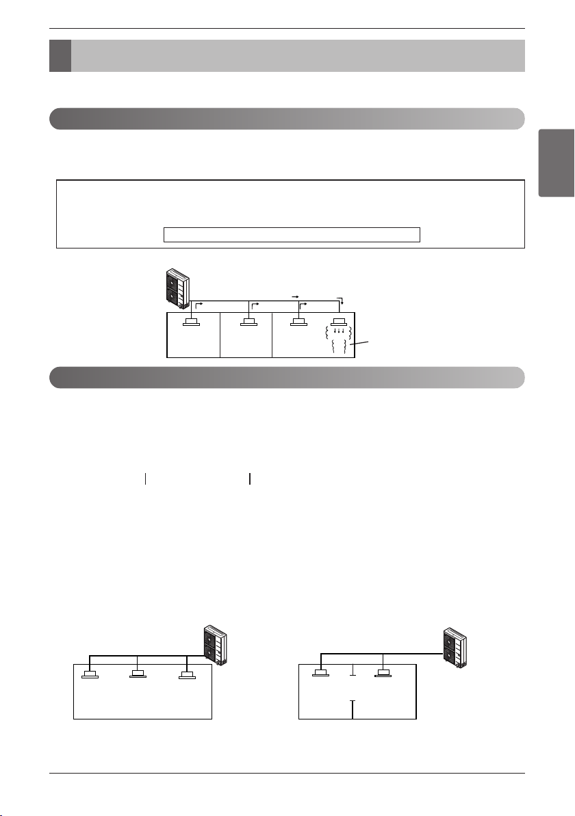
ENGLISH
Installation Manual 63
Caution for Refrigerant Leak
The installer and system specialist shall secure safety against leakage according to local regulations or standards.
The following standards may be applicable if local regulations are not available.
Though the R410A refrigerant is harmless and incombustible itself , the room to equip the air conditioner should be large enough to
such an extent that the refrigerant gas will not exceed the limiting concentration even if the refrigerant gas leaks in the room
.
n Limiting concentration
Check limiting concentration along following steps and take appropriate measure depending on the situation.
n Calculate amount of all the replenished refrigerant (kg (lbs)) per each refrigerant
sys-
tem.
n Calculate minimum room capacity
Calculate room capacity by regarding a portion as one room or the smaller room.
(1) Without partition
(2) With partition and with opening which serve as
passage of air to adjoining room
Caution for Refrigerant Leak
Introduction
Checking procedure of limiting concentration
Limiting concentration is the limit of Freon gas concentration where immediate measures can be taken with-
out hurting human body when refrigerant leaks in the air. The limiting concentration shall be described in the
unit of kg/m
3
(lb/ft
3
) (Freon gas weight per unit air volume) for facilitating calculation.
Limiting concentration: 0.44kg/m
3
(0.028(lb/ft
3
))(R410A)
Outdoor unit
(No.1 system)
Flow of
refrigerant
Indoor unit
Room where refrigerant leaks
(Refrigerant of the whole No.1
system flows out.)
Amount of additional
replenished refrigerant
Total amount of replenished
refrigerant in refrigerant
facility (kg (lbs))
+
=
Note : In case one refrigerant facility is
divided into 2 or more refrigerant
systems and each system is
independent, amount of replenished
refrigerant of each system shall be
adopted.
Outdoor unit
Indoor unit
Outdoor unit
Indoor unit
Opening
Partition
In the case of opening
without door , or 0.15
% or more openings
(to floor space) both
above and below door)
Amount of replenished
refrigerant per one outdoor
unit system
Amount of replenished
refrigerant at factory shipment
Amount of additionally
replenished refrigerant
depending on piping
length or piping
diameter at customer
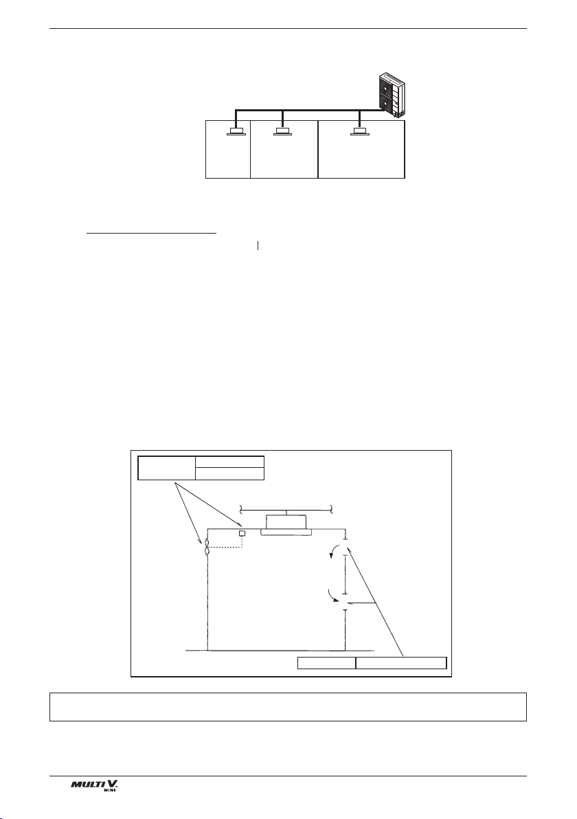
64 Outside Unit
Caution for Refrigerant Leak
(3) With partition and without opening which serve as passage of air to adjoining room
n Calculate refrigerant concentration
n In case the concentration exceeds the limit
When the concentration exceeds the limit, change original plan or take one of the countermeasures
shown below:
• Countermeasure 1
Provide opening for ventilation.
Provide 0.15% or more opening to floor space both above and below door, or provide opening without
door.
• Countermeasure 2
Provide gas leak alarm linked with mechanical ventilator.
Pay special attention to the place, such as a basement, etc. where refrigerant can be present, since
refrigerant is heavier than air.
Outdoor unit
Indoor unit
Smallest
room
(R410A)
Refrigerant concentration
(lb/ft
3
)
Total amount of replenished
refrigerant in refrigerant facility (kg(lbs))
Capacity of smallest room where
indoor unit is installed (ft
3
)
In case the result of calculation exceeds
the limiting concentration, perform the
same calculations by shifting to the
second smallest, and the third smallest
rooms until at last the result is below the
limiting concentration.
Countermeasure 2
Gas leak alarm
Mechanical ventilator
Countermeasure 1
Opening effective to ventilation
Indoor unit
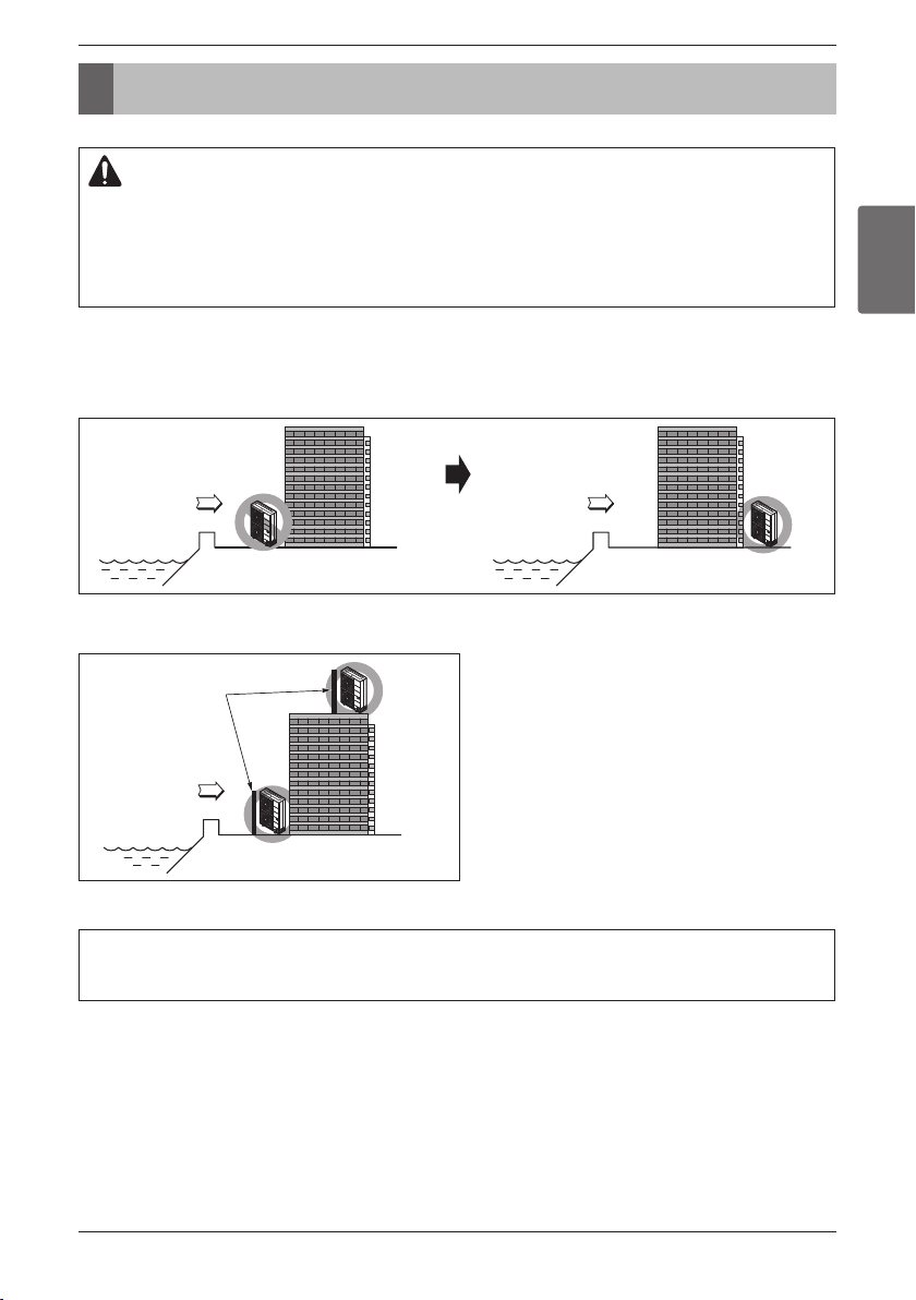
ENGLISH
Installation Manual 65
Installation Guide at the Seaside
Installation Guide at the Seaside
1.
Air conditioners should not be installed in areas where corrosive gases, such as acid or alkaline gas, are produced.
2. Do not install the product where it could be exposed to sea wind (salty wind) directly. It can result corrosion
on the product. Corrosion, particularly on the condenser and evaporator fins, could cause product malfunc-
tion or inefficient performance.
3. If outdoor unit is installed close to the seaside, it should avoid direct exposure to the sea wind. Otherwise it
needs additional anticorrosion treatment on the heat exchanger.
1.
If you can’t meet above guide line in the seaside installation, please contact LG Electronics for the additional anticorrosion treatment.
2. Periodic ( more than once/year ) cleaning of the dust or salt particles stuck on the heat exchanger by using water
Selecting the location(Outdoor Unit)
1) If the outdoor unit is to be installed close to the seaside, direct exposure to the sea wind should be avoided.
Install the outdoor unit on the opposite side of the sea wind direction.
2) In case, to install the outdoor unit on the seaside, set up a windbreak not to be exposed to the sea wind.
3) Select a well-drained place.
• It should be strong enough like concrete to prevent
the sea wind from the sea.
• The height and width should be more than 150% of
the outdoor unit.
• It should be keep more than 70cm(27 5/9 inch)
of space between outdoor unit and the windbreak
for easy air flow.
Sea wind Sea wind
CAUTION
Sea wind
Windbreak
66 Outside Unit
Installation Guide at the Seaside

USA, press #2 for PTAC, TTW
USA, press #3 for DFS, Multi V
CANADA
888-865-3026
888-865-3026
1-888-LG-Canada
www.lge.com
LG Customer Information Center
Register your product Online!
LGEUS
LG Electronics, Air conditioning Division
1000 Sylvan Ave., Englewood Cliffs, NJ 07632
LGECI
LG Electronics Canada Inc.
550 Matheson Blvd. East, Mississauga, Ontario, L4Z 4G3
US
Please call the installing contractor of your product, as warranty service will be
provided by them.
CANADA
Service call Number # : (888) LG Canada, (888) 542-2623
Numéro pour les appels de service : LG Canada, 1-888-542-2623