Loading ...
Loading ...
Loading ...
6
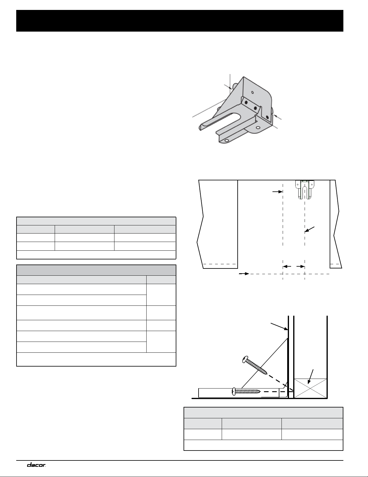
Using the graphic in Step 4 and the final installation cabinet/cutout
dimensions, find the range’s center line and front panel location.
1. Determine and mark the position of the anti-tip bracket.
2. Place the bracket in position, and mark a dot at the notch on
each side of the bracket.
3. Drill just deep enough to see if the bit contacts the base plate.
- If the bit contacts the base plate, wall mounting is suitable.
- If the bit does not contact the base plate, you must either
floor-mount the bracket.)
4. Place the bracket against the wall in the mounting location.
Using a 1/8” bit, drill four 1-5/8” deep pilot holes perpendicular
to the screw-seating surfaces shown below. Attach the bracket
to the wall as shown with the included #12 x 1-3/4 screws.
ANTI-TIP BRACKET PLACEMENT
Dimension HGPR36S HGPR48S
C 11-7/8” (30.2 cm) 2-1/2” (6.4 cm)
*Excludes bull nose (see Pg. 3)
3. Determine the screw size required. The minimum full thread
depth (portion of screw threaded into wood/slab) for wood is
3/8” (1 cm) and 5/8” (1.6 cm) for concrete. See SCREW SIZE
TABLE to select the correct screw size.
Anchoring the Bracket To Concrete
1. Drill four 3/8”-diameter countersink holes through any existing
floor covering to (but not into) the concrete slab.
2. With a 3/16” masonry bit, drill four anchor holes 1-1/4” (3.2 cm)
into the concrete slab.
The hole must be longer than the anchor for proper installation.
3. Clear the holes of dust and debris, then tap the anchors into
the holes so the top is flush with the slab.
4. Position the anti-tip bracket over the anchor holes.
5. Insert the screws through the 4 holes in the base of the
bracket, and thread them into the anchors.
Ensure the screw threads engage the anchor.
6. Tighten the screws.
Attaching the Bracket To a Wooden Sub-Floor
1. If there is a hard floor covering (e.g., ceramic, asphalt), drill
four countersink holes to (but not into) the wood sub-floor.
2. (With a 1/16” bit for #8 screws or a 1/8” bit for #12 screws)
Drill four pilot holes into the wood sub-floor.
3. Align the anti-tip bracket holes with the holes in the floor.
4. Insert and tighten the four screws.
ANTI-TIP BRACKET PLACEMENT
Dimension HGPR36S HGPR48S
A 10-7/8” (27.6 cm) 1-1/2” (3.8 cm)
B 22-1/2” (57.2 cm) 22-1/2” (57.2 cm)
*Excludes bull nose (see Pg. 3)
SCREW SIZE TABLE
Sub-Floor Type/Floor Covering Thickness Screw
Concrete or wood sub-floor, no floor covering
#8 x 1*
Concrete/wood sub-floor, floor covering up to ¼” thick
Concrete/wood sub-floor, floor covering over ¼”, up to
½” thick
#8 x 1 ¼ *
Wood sub-floor, floor covering over ½”, up to 1 3/16” thick #12 x 1 ¾ *
Concrete under floor covering over ½” thick
Not
included**
Wood sub-floor, floor covering over 1-3/16” thick
*Included with range; **Determine required depth based on information in
Step 3 and purchase from local hardware store.
Wall-Mounting the Anti-Tip Bracket
• To use this option:
- the range’s front panel (exterior surface of the door—not the
forward edge of the bull nose) must be 27 in. (68.6 cm) or
less from the wall behind the range.
- the bracket screws must be able to thread into the wall’s base
plate (see the graphic, Step 5, Pg. 7).
• Notches on the bracket sides indicate the minimum required
height of the base plate and that any floor covering does not
keep screw threads from engaging the base plate.
Installation Instructions
Range
center line
C
L
C
L
Bracket
center
line
Range front panel*
C
Wall
Stud
Base
plate
Drywall
Loading ...
Loading ...
Loading ...