HT-IS100
Operating Instructions
Manual de instrucciones
©2008 Sony Corporation
3-299-270-11(2)
Home Theatre
System
GB
US
ES
2
US
3
To reduce the risk of fire or electric
shock, do not expose this apparatus to
rain or moisture.
Batteries or batteries installed apparatus shall not be
exposed to excessive heat such as sunshine, fire or the
like.
Do not install the appliance in a confined space, such as
a bookcase or built-in cabinet.
In door use only.
For the customers in the U.S.A
This symbol is intended to alert the user to
the presence of uninsulated “dangerous
voltage” within the product’s enclosure that
may be of sufficient magnitude to constitute a risk of
electric shock to persons.
This symbol is intended to alert the user to
the presence of important operating and
maintenance (servicing) instructions in the
literature accompanying the appliance.
For the customers in Argentina
To prevent fire, do not cover the ventilation of the
apparatus with news papers, table-cloths, curtains, etc.
And don’t place lighted candles on the apparatus.
For the customers in Canada and
Argentina
To prevent fire or shock hazard, do not place objects
filled with liquids, such as vases, on the apparatus.
Important Safety Instructions
1) Read these instructions.
2) Keep these instructions.
3) Heed all warnings.
4) Follow all instructions.
5) Do not use this apparatus near water.
6) Clean only with dry cloth.
7) Do not block any ventilation openings. Install in
accordance with the manufacturer’s instructions.
8) Do not install near any heat sources such as
radiators, heat registers, stoves, or other apparatus
(including amplifiers) that produce heat.
9) Do not defeat the safety purpose of the polarized or
grounding-type plug. A polarized plug has two
blades with one wider than the other. A grounding
type plug has two blades and a third grounding
prong. The wide blade or the third prong are
provided for your safety. If the provided plug does
not fit into your outlet, consult an electrician for
replacement of the obsolete outlet.
10) Protect the power cord from being walked on or
pinched particularly at plugs, convenience
receptacles, and the point where they exit from the
apparatus.
11) Only use attachments/accessories specified by the
manufacturer.
12) Use only with the cart, stand, tripod, bracket, or
table specified by the manufacturer, or sold with the
apparatus. When a cart is used, use caution when
moving the cart/apparatus combination to avoid
injury from tip-over.
13) Unplug this apparatus during lightning storms or
when unused for long periods of time.
14) Refer all servicing to qualified service personnel.
Servicing is required when the apparatus has been
damaged in any way, such as power-supply cord or
plug is damaged, liquid has been spilled or objects
have fallen into the apparatus, the apparatus has
been exposed to rain or moisture, does not operate
normally, or has been dropped.
WARNING

3
US
GB
US
WARNING
This equipment has been tested and found to comply
with the limits for a Class B digital device, pursuant to
Part 15 of the FCC Rules. These limits are designed to
provide reasonable protection against harmful
interference in a residential installation. This
equipment generates, uses, and can radiate radio
frequency energy and, if not installed and used in
accordance with the instructions, may cause harmful
interference to radio communications. However, there
is no guarantee that interference will not occur in a
particular installation. If this equipment does cause
harmful interference to radio or television reception,
which can be determined by turning the equipment off
and on, the user is encouraged to try to correct the
interference by one or more of the following measures:
– Reorient or relocate the receiving antenna.
– Increase the separation between the equipment and
receiver.
– Connect the equipment into an outlet on a circuit
different from that to which the receiver is
connected.
– Consult the dealer or an experienced radio/TV
technician for help.
CAUTION
You are cautioned that any changes or modifications
not expressly approved in this manual could void your
authority to operate this equipment.
Note to CATV system installer:
This reminder is provided to call the CATV system
installer’s attention to Article 820-40 of the NEC that
provides guidelines for proper grounding and, in
particular, specifies that the cable ground shall be
connected to the grounding system of the building, as
close to the point of cable entry as practical.
Owner’s Record
The model and serial numbers are located at the rear of the
subwoofer. Record the serial numbers in the spaces
provided below. Refer to them whenever you call upon
your Sony dealer regarding this product.
Model No. HT-IS100
Serial No.
This system incorporates Dolby* Digital and Pro Logic
Surround and the DTS** Digital Surround System.
* Manufactured under license from Dolby
Laboratories.
“Dolby”, “Pro Logic”, and the double-D symbol are
trademarks of Dolby Laboratories.
**Manufactured under license under U.S. Patent #'s:
5,451,942; 5,956,674; 5,974,380; 5,978,762;
6,487,535 & other U.S. and worldwide patents
issued & pending. DTS and DTS Digital Surround
are registered trademarks and the DTS logos and
Symbol are trademarks of DTS, Inc. © 1996-2007
DTS, Inc. All Rights Reserved.
This system incorporates High-Definition Multimedia
Interface (HDMI™) technology.
HDMI, the HDMI logo and High-Definition
Multimedia Interface are trademarks or registered
trademarks of HDMI Licensing LLC.
“BRAVIA” is a trademark of Sony Corporation.
“S-AIR” and its logo are trademarks of Sony
Corporation.

4
US
On safety
• Should any solid object or liquid fall into the system,
unplug the system and have it checked by qualified
personnel before operating it any further.
• Do not climb on the subwoofer, as you may fall down
and injure yourself, or system damage may result.
On power sources
• Before operating the system, check that the operating
voltage is identical to your local power supply. The
operating voltage is indicated on the nameplate at the
rear of the subwoofer.
• If you are not going to use the system for a long time,
be sure to disconnect the system from the wall outlet
(mains). To disconnect the AC power cord (mains
lead), grasp the plug itself; never pull the cord.
• One blade of the plug is wider than the other for the
purpose of safety and will fit into the wall outlet
(mains) only one way. If you are unable to insert the
plug fully into the outlet, contact your dealer.
• AC power cord (mains lead) must be changed only at
the qualified service shop.
• The system is not disconnected from the AC power
source (mains) as long as it is connected to the wall
outlet, even if the system itself has been turned off.
• Install this system so that the power cord can be
unplugged from the wall socket immediately in the
event of trouble.
On heat buildup
Although the system heats up during operation, this is
not a malfunction. If you continuously use this system
at a large volume, the system temperature of the back
and bottom rises considerably. To avoid burning
yourself, do not touch the system.
On placement
• Place the system in a location with adequate
ventilation to prevent heat buildup and prolong the
life of the system.
• Do not place the system near heat sources, or in a
place subject to direct sunlight, excessive dust, or
mechanical shock.
• Do not place anything at the rear of the subwoofer
that might block the ventilation holes and cause
malfunctions.
• Do not place the system near equipment such as a TV,
VCR, or tape deck. (If the system is being used in
combination with a TV, VCR, or tape deck, and is
placed too close to that equipment, noise may result,
and picture quality may suffer. This is especially
likely when using an indoor antenna. Therefore, we
recommend using an outdoor antenna.)
• Use caution when placing the system on surfaces that
have been specially treated (with wax, oil, polish, etc.)
as staining or discoloration of the surface may result.
On operation
Before connecting other components, be sure to turn off
and unplug the system.
If you encounter color irregularity on
a nearby TV screen
The system is magnetically shielded to allow it to be
installed near a TV set. However, color irregularities
may still be observed on certain types of TV sets.
If color irregularity is observed...
Turn off the TV set, then turn it on again after 15 to 30
minutes.
If color irregularity is observed
again...
Place the system further away from the TV set.
On cleaning
Clean the system with a soft dry cloth. Do not use any
type of abrasive pad, scouring powder or solvent such
as alcohol or benzine.
If you have any question or problem concerning your
system, please consult your nearest Sony dealer.
Precautions

5
US
Precautions...............................................4
Getting Started
Supplied Accessories ...............................6
Step 1: Positioning the Speakers..............7
Step 2: Connecting the Speakers............15
Step 3a: Connecting the Components with
HDMI Jacks.....................................16
Step 3b: Connecting the Components
without HDMI Jacks........................18
Step 4: Connecting the Antenna (Aerial)
.........................................................22
Step 5: Connecting the AC Power Cord
(Mains Lead)....................................24
Step 6: Calibrating the Appropriate
Settings Automatically ....................24
(Auto Calibration)
Setting up the Sound Output of the
Connected Component ....................28
Function for Conversion of Video Signals
.........................................................29
Connecting the Other Components........30
Playback Options
Index to Parts and Controls....................32
Enjoying TV...........................................35
Enjoying Other Components..................36
Surround Functions
Enjoying the Surround Effects...............38
Adjusting the Bass, Middle, and Treble
Level ................................................40
Enjoying the Movies at Night................40
“BRAVIA” Sync features
What is “BRAVIA” Sync?.....................41
Preparing for the “BRAVIA” Sync........41
Enjoying a Blu-ray Disc/DVD...............43
(One-Touch Play)
Enjoying the TV sound from the
Speakers...........................................43
(System Audio Control)
Turning off the TV, System, and
Connected Components...................45
(System Power Off)
Tuner Functions
Presetting Radio Stations ...................... 46
Listening to the Radio........................... 47
Advanced Settings
Controlling the Connected Sony
Components with the Remote......... 50
Changing the Input Button Assignments of
the Remote ...................................... 52
Settings and Adjustments Using the
Amplifier Menu .............................. 54
Reassigning the audio inputs................. 63
Using an S-AIR Product........................ 65
Using the IR repeater............................. 72
Additional Information
Troubleshooting .................................... 73
Specifications ........................................ 76
Glossary................................................. 78
Index...................................................... 79
Table of Contents

6
US
Please check the following accessories in the
package.
Remote commander (RM-AAU036) (1)
Size AA (R6) batteries (2)
Optical cable (2.5 m) (98
1
/
2
inches) (1)
FM wire antenna (aerial) (1)
AM loop antenna (aerial) (1)
Calibration mic (1)
Speaker (with Remote commander
receiver) (1)
Speakers (4)
Extra speaker pedestal (1)
Brackets (5)
Wrench (1)
Screw (+PSW4 × 12) (1)
Operating Instructions (1)
Quick Start Guide (card) (1)
Inserting batteries into the
remote
You can control the system using the supplied
remote. Insert two size AA (R6) batteries by
matching the + and – ends on the batteries to the
markings inside the compartment.
• Do not leave the remote in an extremely hot or humid
place.
• Do not use a new battery with an old one.
• Do not drop any foreign object into the remote casing,
particularly when replacing the batteries.
• Do not expose the remote sensor ( ) to direct light
from the sun or lighting apparatus. Doing so may
cause a malfunction.
• If you do not intend to use the remote for an extended
period of time, remove the batteries to avoid possible
damage from battery leakage and corrosion.
Getting Started
Supplied Accessories
Notes
7
US
Getting Started
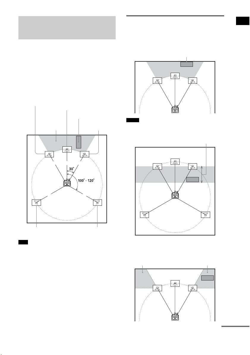
For the best possible surround sound, all the
speakers other than the subwoofer should be
placed at the same distance from the listening
position (1). Sony recommends that the
subwoofer should be placed (2).
Place speakers and subwoofer as illustrated
below.
• You can also place the subwoofer either side, facing
the listening position.
• When you install the speaker, the speaker face may be
unstable. In this case, use a commercially available
wire clamper or a commercially available tape, etc., to
secure the speaker cord.
Using the subwoofer
efficiently
To reinforce the bass sound, place the subwoofer
possible close to a wall.
• If the subwoofer is to be placed ahead of the front
speaker, the distance should be less than 0.5 m (1.6
ft).*
• You may not get the bass sound efficiently when the
subwoofer is placed outside (3). You need to adjust
the setting of the distance from the listening position.
Step 1: Positioning the
Speakers
Tips
1 1 1
11
2
Subwoofer
Center speaker
Front right speaker
Front left speaker
Surround left speaker Surround right speaker
Notes
Close to a wall
*
33
continued
8
US
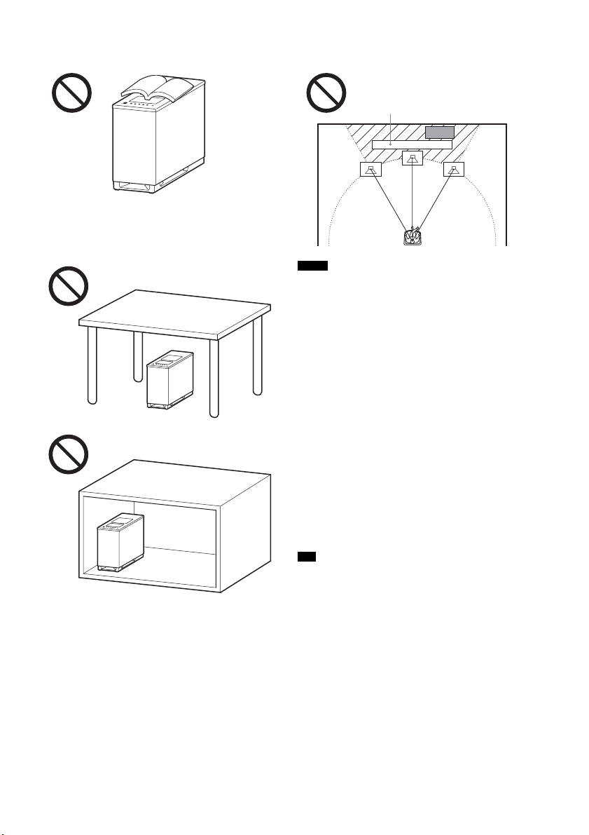
• Do not place objects on the top of the subwoofer
where the speaker unit is installed.
• Do not place the subwoofer under a desk or in a
cabinet, etc.
• Do not place the subwoofer back of the obstruction,
such as TV, etc. Middle range sound will fall.
• Do not set the speakers in an inclined position.
• Do not place the speakers in locations that are:
– Extremely hot or cold
– Dusty or dirty
– Very humid
– Subject to vibrations
– Subject to direct sunlight
• Use caution when placing the speakers and/or speaker
stands (not supplied) that are attached with the
speakers on a specially treated (waxed, oiled,
polished, etc.) floor, as staining or discoloration may
result.
• When cleaning, use a soft cloth such as a cleaning
cloth for glasses.
• Do not use any type of abrasive pad, scouring powder,
or solvent such as alcohol or benzine.
• Image distortion on the TV screen may occur
depending on the location of the subwoofer. In this
case, place the subwoofer away from the TV.
• When you change the positions of the speakers, Sony
recommends that you change the settings. For details,
see “Step 6: Calibrating the Appropriate Settings
Automatically” (page 24).
Notes
Tip
TV, etc.
9
US
Getting Started
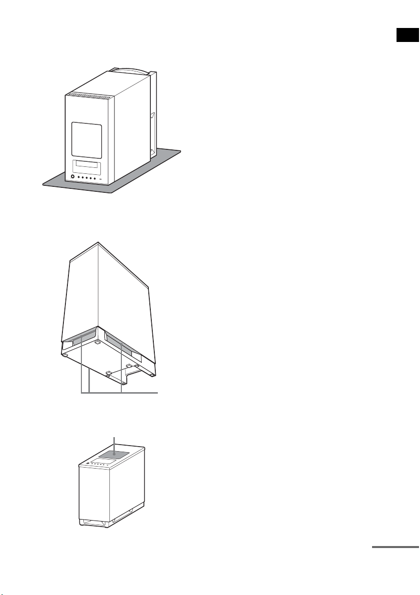
Notes on handling the subwoofer
• Place a soft cloth under the subwoofer when you lay
the subwoofer down for connection.
• Do not place your hand into the slit of the subwoofer
when lifting it. The speaker driver may be damaged.
When lifting, hold the bottom of the subwoofer.
• Do not push the top of the subwoofer where the
speaker unit is installed.
Slits
Speaker unit
continued
10
US
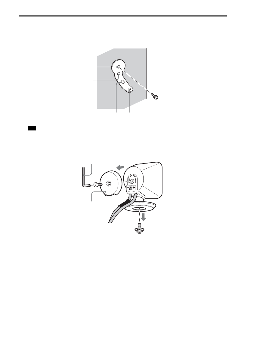
Installing the speakers on a wall
1 Prepare screws (not supplied) that are suitable for the holes of the bracket.
2 Secure the bracket to the wall using hole 1.
• To prevent the speaker from rotating, use the hole 2, too.
3 Remove the rear cap using the wrench (supplied), and remove the speaker pedestal
using a screwdriver (+) (not supplied).
Tip
1
34
2
Rear cap
Wrench (supplied)
11
US
Getting Started
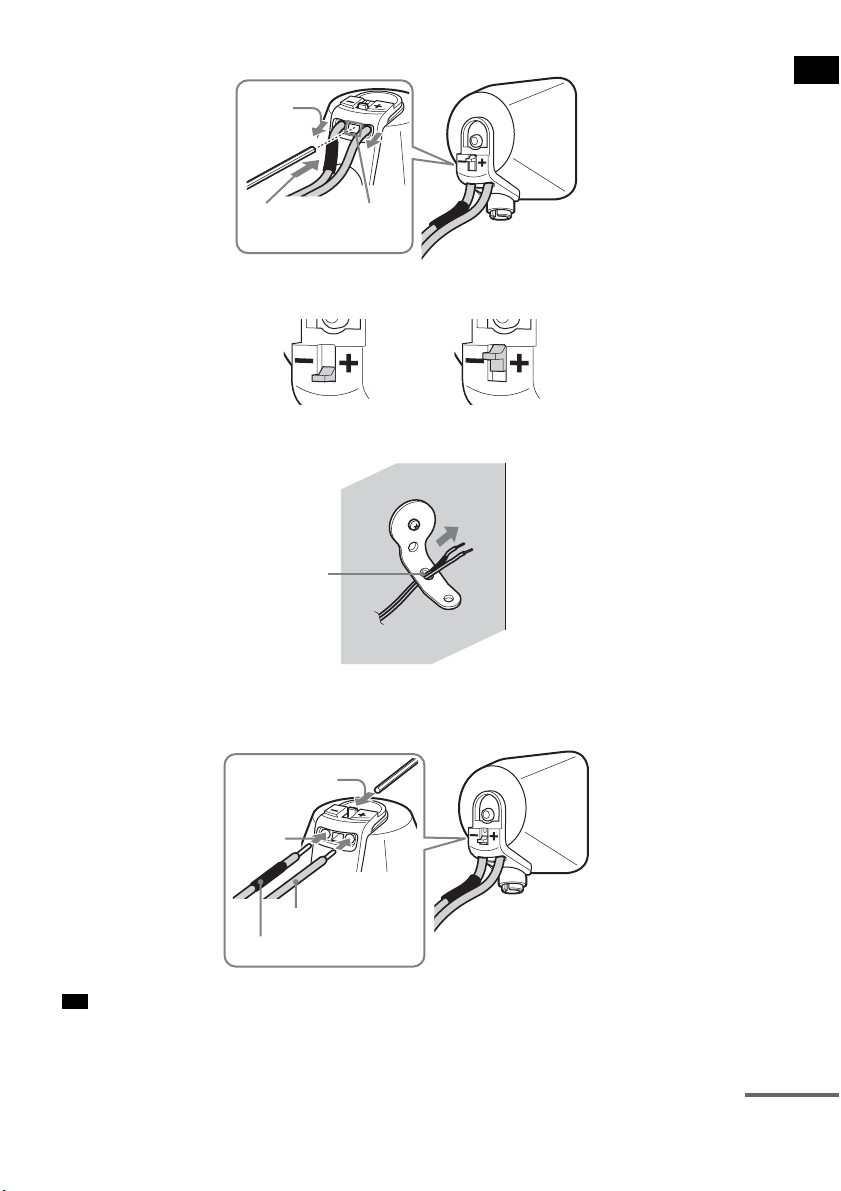
4 Push A with the supplied wrench (1), and then remove the speaker cords (2).
5 Thread the speaker cords through hole 3.
6 Reconnect the detached speaker cords, matching 3/# to the appropriate speaker
terminals (1), and then push the lever down completely (2).
• If it is difficult to push the lever down, use the wrench (supplied).
Tip
(1)
When the lever is down, the
speaker cords are locked.
When the lever is up, the
speaker cords can be removed.
(2)
A
3
#
3
(1)
(2)
continued

12
US
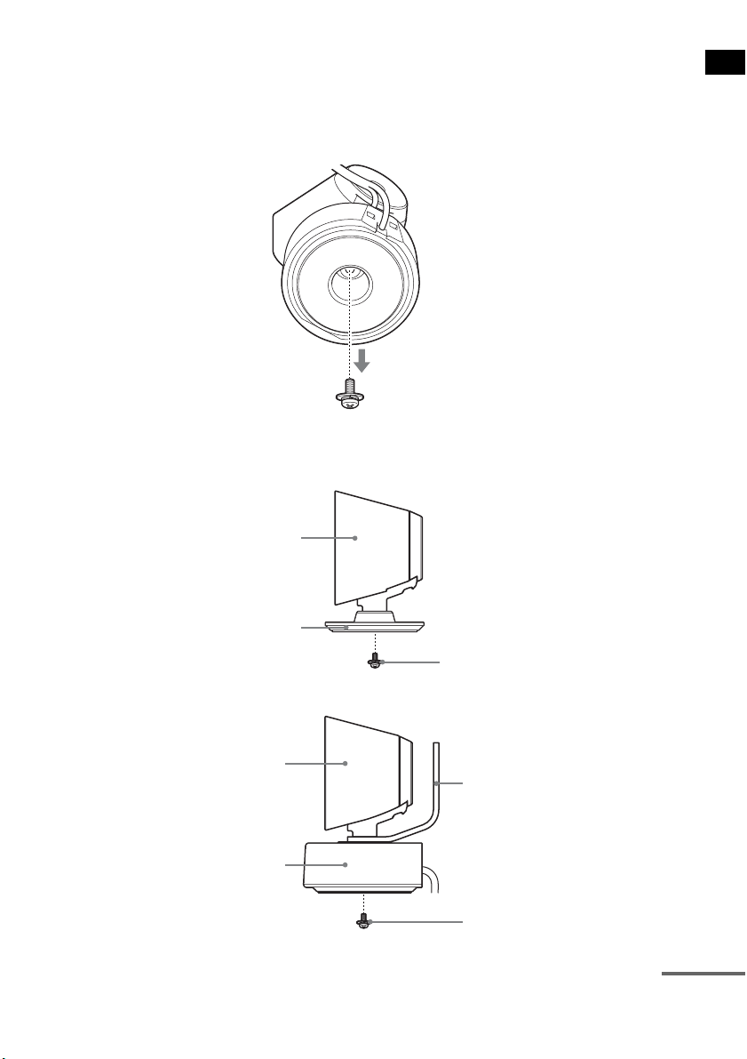
7 Reattach the rear cap using the wrench (supplied).
8 Secure the speaker to the bracket with the screw in step 3 using hole 4.
CAUTION
• Do not place any load on the bracket, other than that of the speaker. If you do so, the speaker may fall and cause
injury or property damage.
• Do not hang from the speaker or the bracket, as it may fall on you and cause serious injury.
• Use screws that are suitable for the wall material and strength. As a plaster board wall is especially fragile, attach
the screws securely to a beam and fasten them to the wall. Install the speakers on a vertical and flat wall where
reinforcement is applied.
• Contact a screw shop or installer regarding the wall material or screws to be used.
• Sony is not responsible for accident or damage caused by improper installation, insufficient wall strength or
improper screw installation, natural calamity, etc.
Notes
4
13
US
Getting Started
About the center speaker
You can remove the remote commander receiver from the center speaker, allowing them to be used
separately.
You can also install the remote commander receiver with the center speaker on a wall.
1 Remove the remote commander receiver using a screwdriver (+) (not supplied).
2 Secure the speaker with the screw.
To use the center speaker and remote commander receiver separately.
To install the remote commander receiver on a wall.
Center speaker
Extra speaker pedestal
(supplied)
Screw in step 1
Center speaker
Remote commander receiver
Bracket
Screw (+PSW4 × 12) (supplied)
continued
14
US
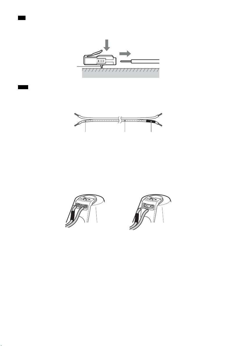
• You can remove the speaker cords from the connector. With the catch facing down, press and hold the connector
down against a flat surface (1) and remove the speaker cords from the connector (2).
• When you reconnect the speaker cords to the connector, be sure to match the speaker cords to the appropriate
speaker terminals: 3 to +, and # to –. Connect the cord with white letters or lines (to which a black tube is also
attached on one side) to –. If the cords are reversed, the sound will lack bass and may be distorted.
To avoid short-circuiting the speakers
Short-circuiting of the speakers may damage the system. To prevent this, be sure to follow these
precautions when connecting the speakers. Make sure the bare wire of each speaker cord does not touch
another speaker terminal or the bare wire of another speaker cord, such as shown below.
Tip
Note
Catch
(1)
(2)
#
White letters or lines Black tube
Stripped speaker cord is
touching another speaker
terminal.
Stripped cords are touching each
other due to excessive removal of
insulation.
15
US
Getting Started
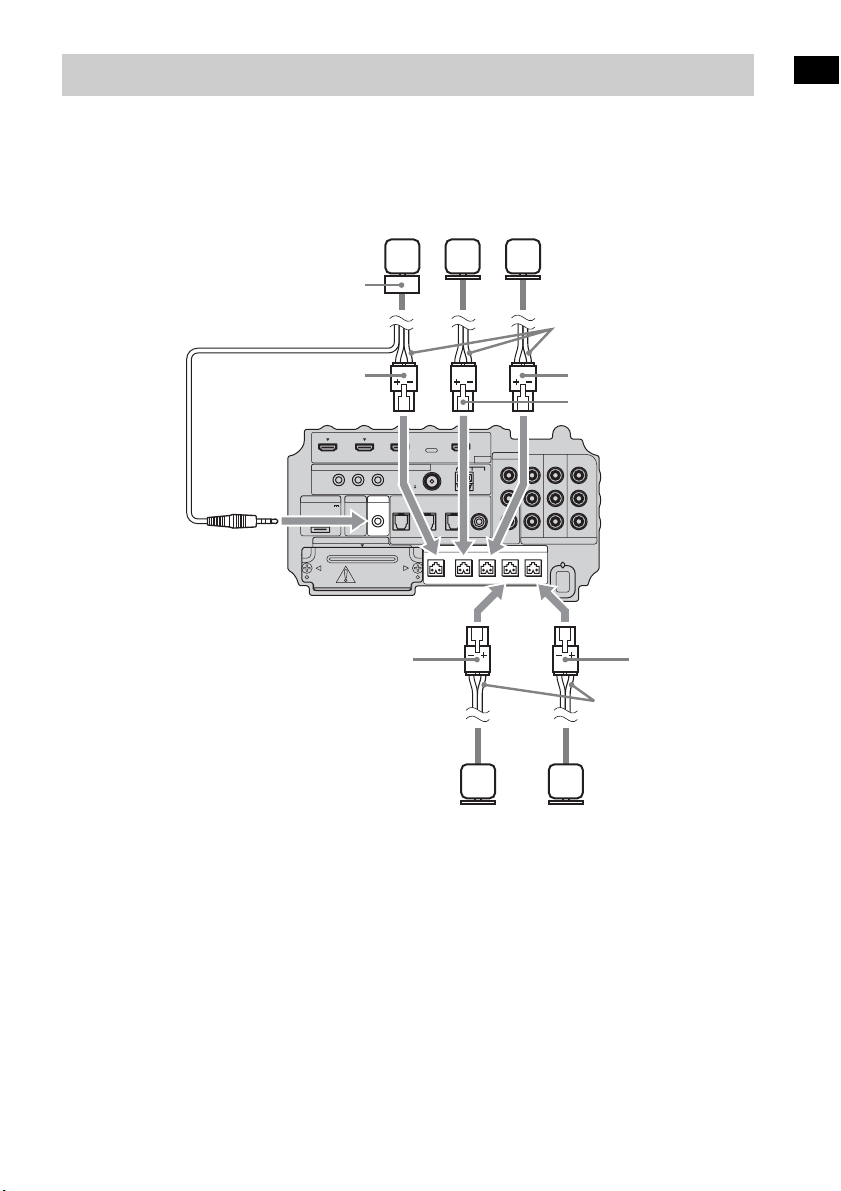
Connect the connectors of the speaker cords to their corresponding SPEAKER jacks. The connectors
of the speaker cords are the same color as the jacks to be connected.
Connect the cord of the remote commander receiver to the IR-R100 jack.
Step 2: Connecting the Speakers
IR REMOTE
VIDEO
DMPORT
SPEAKER ONLY FOR SS-IS15
ECM-AC2 IR-R100
ANTENNA
HDMI
IR IN IR OUT1 IR OUT2
FM AM
75
COAXIAL
DC 5V
0.7A MAX
FRONT R FRONT L SUR R SUR LCENTER
BD IN DVD IN SAT IN
SAT IN
ASSIGNABLE
COAXIAL
AUDI O IN
ASSIGNABLE
VIDEO IN
L
R
TV OUT
EZW-T100 DIGITAL
TV IN DVD IN SAT IN
OPTICAL
COMPONENT VIDEO
DVD IN SAT IN
MONITOR
OUT
Y
P
B/
C
B
PR/
C
R
Speaker cords
Bottom of the
subwoofer
Center
speaker
Front right
speaker
Front left
speaker
Speaker cords
Surround
left speaker
Surround
right speaker
Green
Red
White
Gray
Blue
Remote commander
receiver
16
US
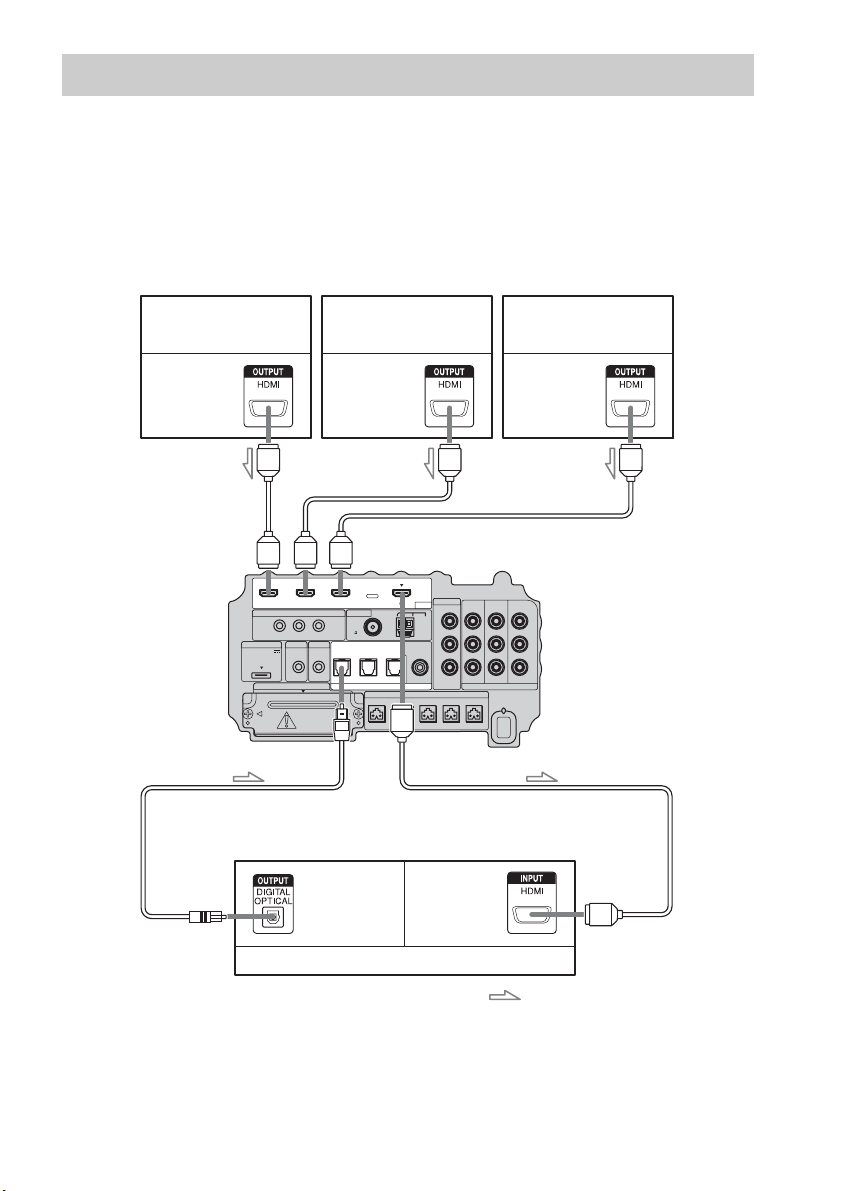
Sony recommends that you connect components to the system using an HDMI cable.
With HDMI, you can easily enjoy both high quality sound and high quality images.
However, it is necessary to connect the audio output of the TV to the audio input of the system
using an optical cable in order to listen to the TV’s sound from the system.
For details on the Control for HDMI function, see ““BRAVIA” Sync features” (page 41).
Step 3a: Connecting the Components with HDMI Jacks
IR REMOTE
VIDEO
DMPORT
SPEAKER ONLY FOR SS-IS15
ECM-AC2 IR-R100
ANTENNA
HDMI
IR IN IR OUT1 IR OUT2
FM AM
75
COAXIAL
DC 5V
0.7A MAX
FRONT R FRONT L SUR R SUR LCENTER
BD IN DVD IN SAT IN
SAT IN
ASSIGNABLE
COAXIAL
AUDI O IN
ASSIGNABLE
VIDEO IN
L
R
TV OUT
EZW-T100 DIGITAL
TV IN DVD IN SAT IN
OPTICAL
COMPONENT VIDEO
DVD IN SAT IN
MONITOR
OUT
Y
P
B/
C
B
PR/
C
R
TV monitor, projector, etc.
A HDMI cable (not supplied)
B Optical cable (supplied)
Blu-ray Disc player (recorder),
“PlayStation 3”
Audio/video
signal
Satellite tuner
Audio/video
signal
B
A
Audio/video
signal
DVD player (recorder)
Audio signal
: Signal flow
A
A
A
Bottom of the
subwoofer
Audio/video
signal

17
US
Getting Started
• For details on connecting to components without HDMI jacks, see page 18.
• The HDMI jack has priority when you connect the component to the system using the HDMI input jacks and other
input jacks at the same time.
Notes on HDMI connections
• You can enjoy high quality images using an HDMI cable with an HDMI logo. Sony recommends that
you use a Sony HDMI cable.
• Check the setup of the connected component if an image is poor or the sound does not come out of a
component connected via the HDMI cable.
• Audio signals (sampling frequency, bit length, etc.) transmitted from an HDMI jack may be
suppressed by the connected component.
• Sound may be interrupted when the sampling frequency or the number of channels of audio output
signals from the playback component is switched.
• When the connected component is not compatible with copyright protection technology (HDCP), the
image and/or the sound from the HDMI TV OUT jack may be distorted or may be not output.
In this case, check the specification of the connected component.
• Sony does not recommend using an HDMI-DVI conversion cable.
• Regardless of which input is selected for the system, video signals from the input jack selected the
last time are output from the HDMI TV OUT jack.
Notes
18
US
When you connect a DVD player (recorder), satellite tuner, VCR, etc., that has no HDMI jacks, you
can choose the connecting combination of the system. This subwoofer is equipped with a function for
converting video signals. For details, see “Function for Conversion of Video Signals” (page 29).
Connecting a TV monitor
The image from a visual component connected to this subwoofer can be displayed on a TV monitor,
projector, etc.
• Connect image display components such as a TV or a projector to the MONITOR OUT jacks on the subwoofer.
• Be sure to turn on the subwoofer when the video and audio of a playback component are being output to a TV via
the subwoofer. If the power supply of the subwoofer is not turned on, neither video nor audio signal is transmitted.
• You can reassign the analog audio input using the AUDIO IN ASSIGNABLE jacks. For details, see “Reassigning
the analog audio input” (page 63).
• You can watch the selected input image when you connect the MONITOR OUT jack to a TV.
Step 3b: Connecting the Components without HDMI Jacks
Notes
Tips
IR REMOTE
VIDEO
DMPORT
SPEAKER ONLY FOR SS-IS15
ECM-AC2 IR-R100
ANTENNA
HDMI
IR IN IR OUT1 IR OUT2
FM AM
75
COAXIAL
DC 5V
0.7A MAX
FRONT R FRONT L SUR R SUR LCENTER
BD IN DVD IN SAT IN
SAT IN
ASSIGNABLE
COAXIAL
AUDI O IN
ASSIGNABLE
VIDEO IN
L
R
TV OUT
EZW-T100 DIGITAL
TV IN DVD IN SAT IN
OPTICAL
COMPONENT VIDEO
DVD IN SAT IN
MONITOR
OUT
Y
P
B/
C
B
PR/
C
R
INPUT
TV monitor, projector, etc.
A
A Optical cable (supplied)
B Audio cord (not supplied)
C Component video cord (not supplied)
Video signal
: Signal flow
B
Audio signal
Bottom of the
subwoofer
C
or
19
US
Getting Started
• To output the TV sound from the speakers connected to the subwoofer, be sure to
– connect the audio output jacks of the TV to the OPTICAL TV IN jacks of the subwoofer.
– turn off or mute the TV’s volume.
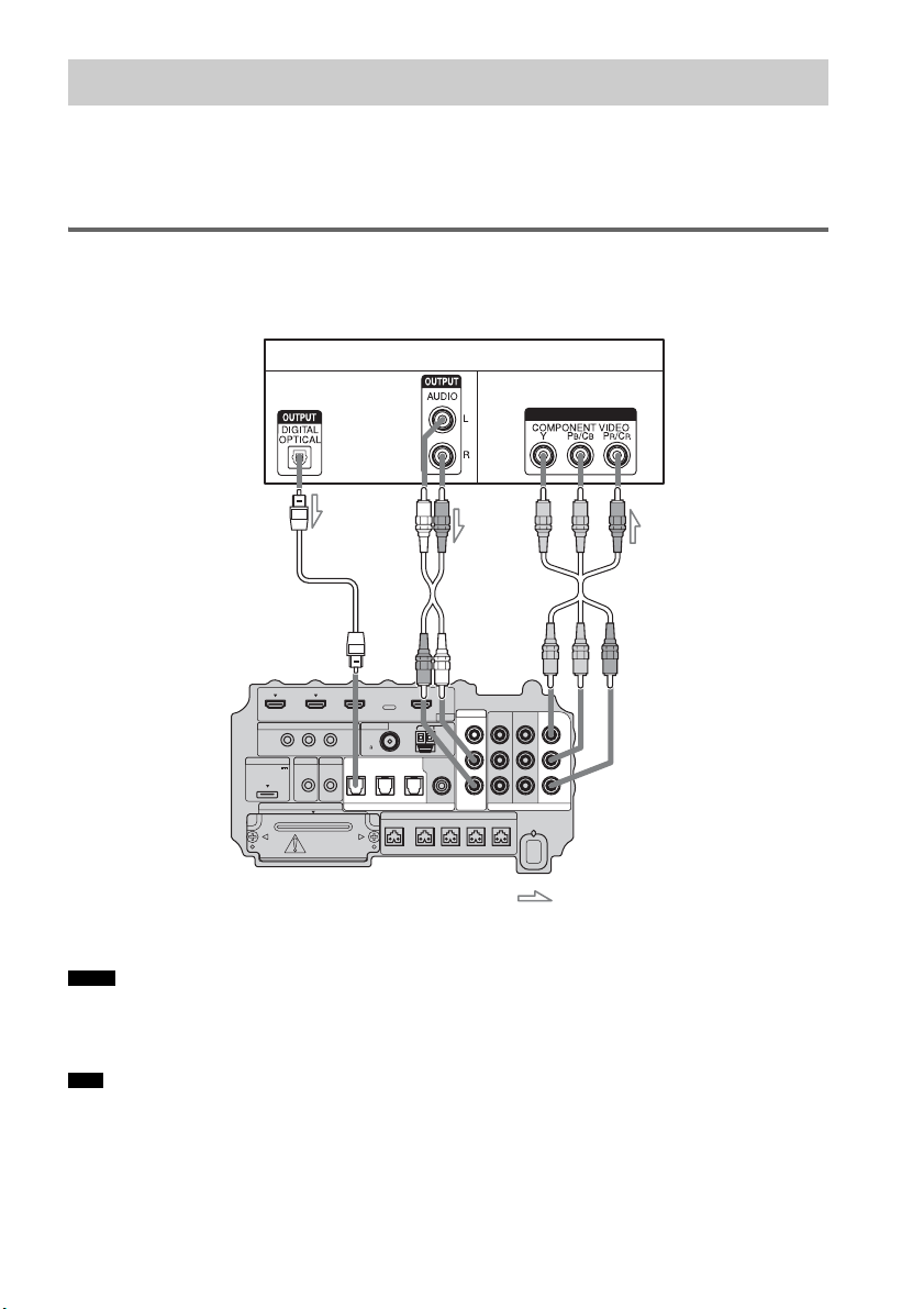
Connecting a DVD player (recorder)
The following illustration shows how to connect a DVD player (recorder).
You can reassign the digital audio input using the ASSIGNABLE COAXIAL SAT IN jack. For details,
see “Reassigning the digital audio input” (page 64).
IR REMOTE
VIDEO
DMPORT
SPEAKER ONLY FOR SS-IS15
ECM-AC2 IR-R100
ANTENNA
HDMI
IR IN IR OUT1 IR OUT2
FM AM
75
COAXIAL
DC 5V
0.7A MAX
FRONT R FRONT L SUR R SUR LCENTER
BD IN DVD IN SAT IN
AUDI O IN
ASSIGNABLE
VIDEO IN
L
R
TV OUT
EZW-T100 DIGITAL
TV IN DVD IN SAT IN
OPTICAL
COMPONENT VIDEO
DVD IN SAT IN
MONITOR
OUT
Y
P
B/
C
B
PR/
C
R
SAT IN
ASSIGNABLE
COAXIAL
DVD player (recorder)
A
A Optical cable (not supplied)
B Coaxial cord (not supplied)
C Component video cord (not supplied)
Video signal
: Signal flow
B
Audio signal
Bottom of the
subwoofer
or
C
continued

20
US
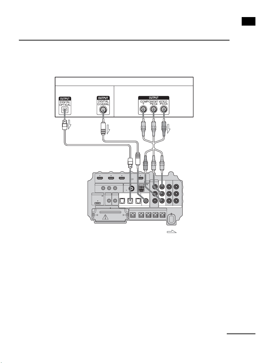
Connecting a satellite tuner
The following illustration shows how to connect a satellite tuner.
If the satellite tuner does not have an OPTICAL OUT jack, connect the system using the COAXIAL
SAT IN jack.
IR REMOTE
VIDEO
DMPORT
SPEAKER ONLY FOR SS-IS15
ECM-AC2 IR-R100
ANTENNA
HDMI
IR IN IR OUT1 IR OUT2
FM AM
75
COAXIAL
DC 5V
0.7A MAX
FRONT R FRONT L SUR R SUR LCENTER
BD IN DVD IN SAT IN
AUDI O IN
ASSIGNABLE
VIDEO IN
L
R
TV OUT
EZW-T100 DIGITAL
TV IN DVD IN SAT IN
OPTICAL
COMPONENT VIDEO
DVD IN SAT IN
MONITOR
OUT
Y
P
B/
C
B
PR/
C
R
SAT IN
ASSIGNABLE
COAXIAL
Satellite tuner
C
A Optical cable (not supplied)
B Coaxial cord (not supplied)
C Component video cord (not supplied)
Video signal
: Signal flow
B
Audio signal
or
A
Bottom of the
subwoofer
21
US
Getting Started
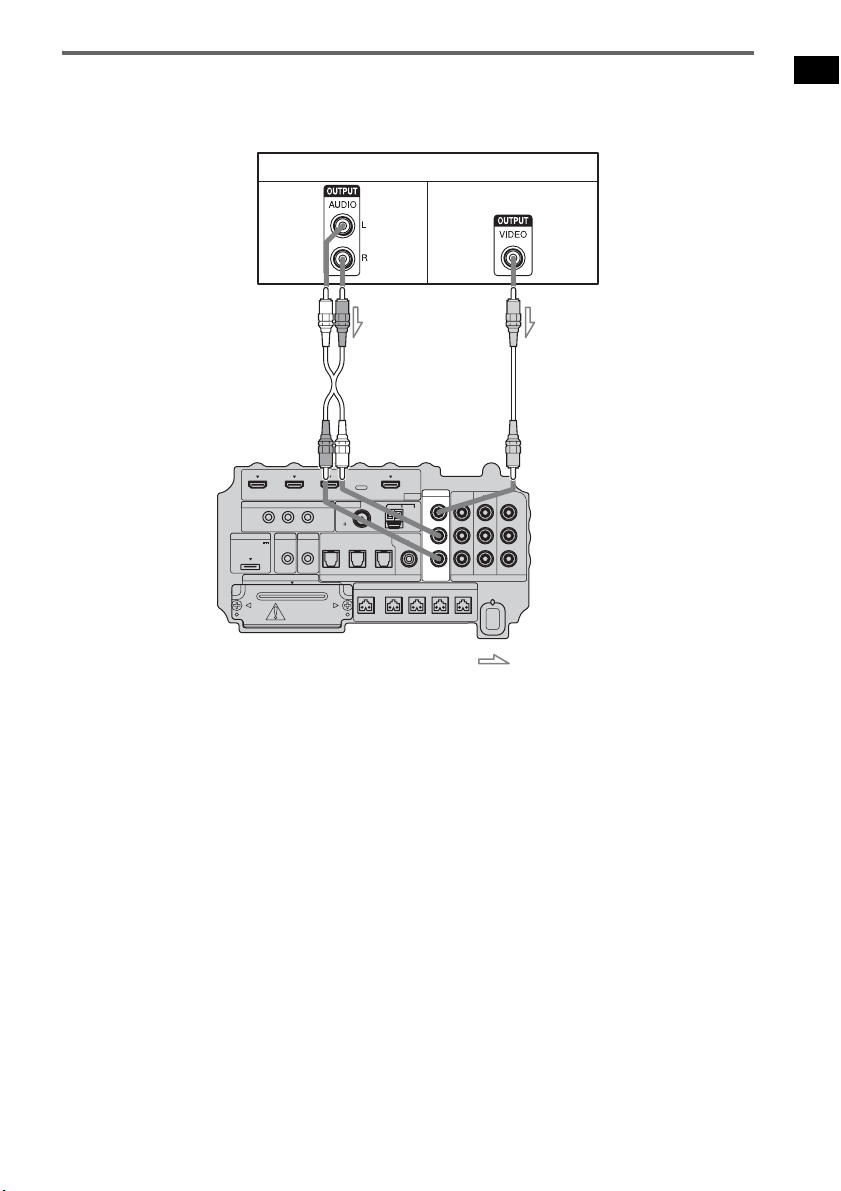
Connecting a VCR
The following illustration shows how to connect a component which has analog jacks such as a VCR,
etc.
IR REMOTE
VIDEO
DMPORT
SPEAKER ONLY FOR SS-IS15
ECM-AC2 IR-R100
ANTENNA
HDMI
IR IN IR OUT1 IR OUT2
FM AM
75
COAXIAL
DC 5V
0.7A MAX
FRONT R FRONT L SUR R SUR LCENTER
BD IN DVD IN SAT IN
AUDI O IN
ASSIGNABLE
VIDEO IN
L
R
TV OUT
EZW-T100 DIGITAL
TV IN DVD IN SAT IN
OPTICAL
COMPONENT VIDEO
DVD IN SAT IN
MONITOR
OUT
Y
P
B/
C
B
PR/
C
R
SAT IN
ASSIGNABLE
COAXIAL
VCR
A
A Audio cord (not supplied)
B Video cord (not supplied)
Video signal
: Signal flow
B
Audio
signal
Bottom of the
subwoofer
22
US
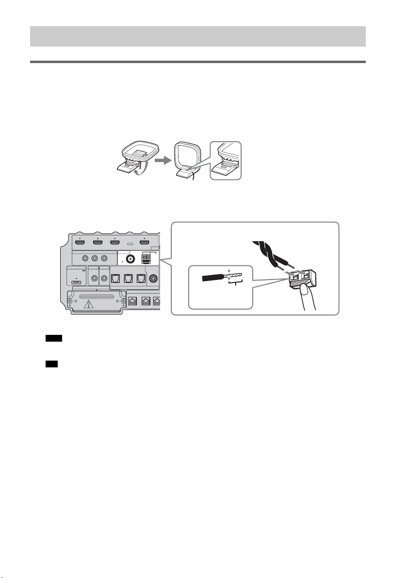
Connecting the AM loop antenna (aerial)
The shape and the length of the antenna (aerial) is designed to receive AM signals. Do not dismantle
or roll up the antenna (aerial).
1 Remove only the loop part from the plastic stand.
2 Set up the AM loop antenna (aerial).
3 Connect the cords to the AM antenna (aerial) terminals.
The cords can be connected to either terminal.
• Do not place the AM loop antenna (aerial) near the system or other AV component, as noise may result.
• Adjust the direction of the AM loop antenna (aerial) for best AM broadcast sound.
4 Make sure the AM loop antenna (aerial) is connected firmly by pulling softly.
Step 4: Connecting the Antenna (Aerial)
Note
Tip
IR REMOTE
DMPORT
SPEAKER ONLY
F
ECM-AC2 IR-R100
ANTENNA
HDMI
IR IN IR OUT1 IR OUT2
FM AM
75
COAXIAL
DC 5V
0.7A MAX
FRONT R FRONT
L
CENTER
BD IN DVD IN SAT IN
SAT IN
ASSIGNABLE
COAXIAL
A
TV OUT
EZW-T100 DIGITAL
TV IN DVD IN SAT IN
OPTICAL
Insert until this
part.
Insert the cords by pushing down the terminal clamp.
Bottom of the subwoofer
23
US
Getting Started
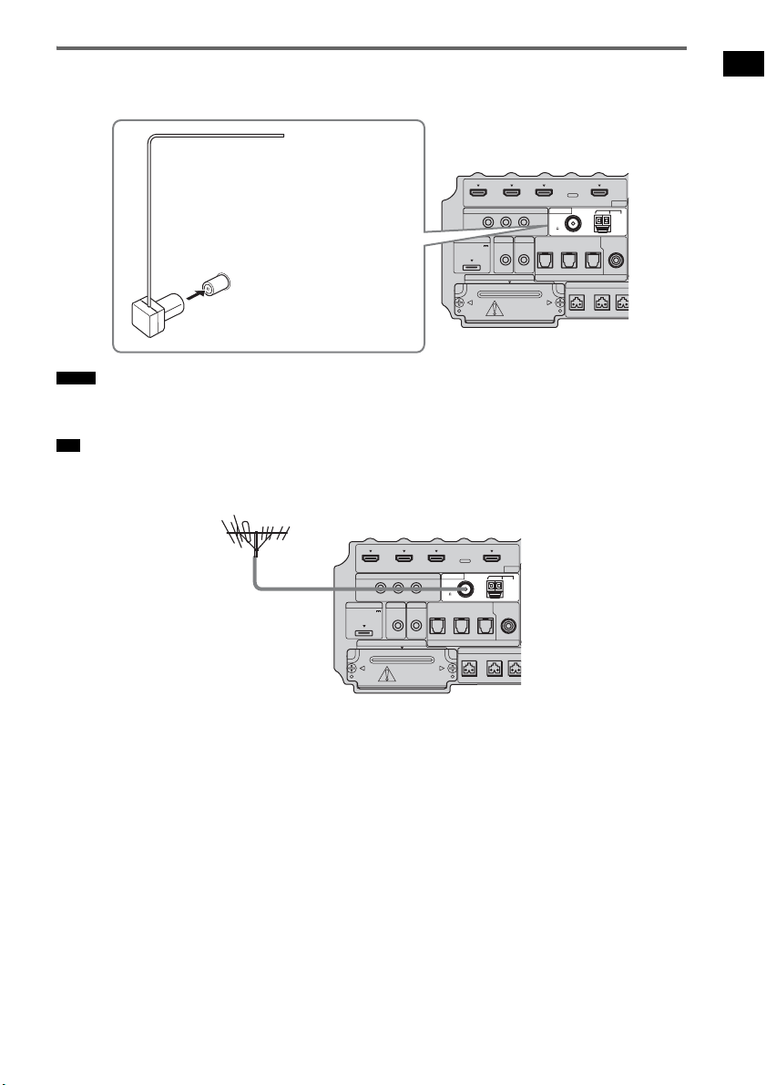
Connecting the FM wire antenna (aerial)
Connect the FM wire antenna (aerial) to the FM 75 Ω COAXIAL jack.
• Be sure to fully extend the FM wire antenna (aerial).
• After connecting the FM wire antenna (aerial), keep it as horizontal as possible.
• If you have poor FM reception, use a 75-ohm coaxial cable (not supplied) to connect the subwoofer to an outdoor
FM antenna (aerial) as shown below.
Notes
Tip
IR REMOTE
DMPORT
SPEAKER ONLY
F
ECM-AC2 IR-R100
ANTENNA
HDMI
IR IN IR OUT1 IR OUT2
FM AM
75
COAXIAL
DC 5V
0.7A MAX
FRONT R FRONT
L
CENTER
BD IN DVD IN SAT IN
SAT IN
ASSIGNABLE
COAXIAL
A
TV OUT
EZW-T100 DIGITAL
TV IN DVD IN SAT IN
OPTICAL
FM wire antenna (aerial)
(supplied)
FM 75 Ω COAXIAL jack
Bottom of the subwoofer
IR REMOTE
DMPORT
SPEAKER ONLY
F
ECM-AC2 IR-R100
ANTENNA
HDMI
IR IN IR OUT1 IR OUT2
FM AM
75
COAXIAL
DC 5V
0.7A MAX
FRONT R FRONT
L
CENTER
BD IN DVD IN SAT IN
SAT IN
ASSIGNABLE
COAXIAL
A
TV OUT
EZW-T100 DIGITAL
TV IN DVD IN SAT IN
OPTICAL
Outdoor FM antenna
(aerial)
Bottom of the subwoofer

24
US
Before connecting the AC power cord (mains
lead) of the subwoofer to a wall outlet (mains),
connect all the speakers to the subwoofer
(page 15).
• After connecting the AC power cord (mains lead),
wait about 20 seconds before turning on the power by
pressing "/1.
This subwoofer is equipped with D.C.A.C.
(Digital Cinema Auto Calibration) Technology
which allows you to perform automatic
calibration as follows:
• Check the connection between each speaker
and the subwoofer.
• Adjust the speaker level.
• Measure the distance of each speaker to your
listening position.
• Measure the frequency characteristics.*
* The measurement result is not utilized for signals
with a sampling frequency of more than 96 kHz.
The D.C.A.C. is designed to obtain proper sound
balance in your room. However, you can adjust
the speaker levels and balance manually
according to your preference. For details, see
“Setting the speaker level” (page 57).
Step 5: Connecting the AC
Power Cord (Mains Lead)
Note
AC power cord
(mains lead)
To a wall outlet
(mains)
Rear of the subwoofer
Step 6: Calibrating the
Appropriate Settings
Automatically
(Auto Calibration)
25
US
Getting Started
Before performing the Auto
Calibration
Before you perform the Auto Calibration, set up
and connect the speakers (page 15).
• The ECM-AC2 jack is used for the calibration
mic (supplied) only. Do not connect other
microphones to this jack. Doing so may
damage the subwoofer and the calibration mic.
• During the calibration, the sound that comes
out of the speakers is very loud. Pay attention
to the presence of children or to the effect on
your neighborhood.
• Perform the Auto Calibration in a quiet
environment to avoid the effect of noise and to
get a more accurate measurement.
• If there are any obstacles in the path between
the calibration mic and the speakers, the
calibration cannot be performed correctly.
Remove any obstacles from the measurement
area to avoid measurement error.
• If the muting function is on when you perform the
Auto Calibration, it will turn off automatically.
• When you use the S-AIR product, disconnect the
headphones.
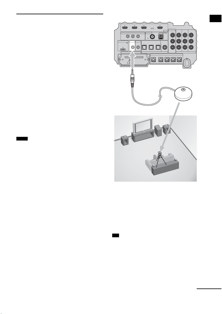
1 Connect the calibration mic (supplied)
to the ECM-AC2 jack on the subwoofer.
2 Set up the calibration mic.
Place the calibration mic at your listening
position. You can also use a stool or tripod
so that the calibration mic remains at the
same height as your ears.
• The front of each speaker should face the calibration
mic. You will get a more accurate measurement.
Notes
Tip
IR REMOTE
VIDEO
DMPORT
SPEAKER ONLY FOR SS-IS15
ECM-AC2 IR-R100
ANTENNA
HDMI
IR IN IR OUT1 IR OUT2
FM AM
75
COAXIAL
DC 5V
0.7A MAX
FRONT R FRONT L SUR R SUR LCENTER
BD IN DVD IN SAT IN
SAT IN
ASSIGNABLE
COAXIAL
AUDI O IN
ASSIGNABLE
VIDEO IN
L
R
TV OUT
EZW-T100 DIGITAL
TV IN DVD IN SAT IN
OPTICAL
COMPONENT VIDEO
DVD IN SAT IN
MONITOR
OUT
Y
P
B/
C
B
PR/
C
R
Bottom of the subwoofer
To ECM-AC2 jack
Calibration mic
continued
26
US
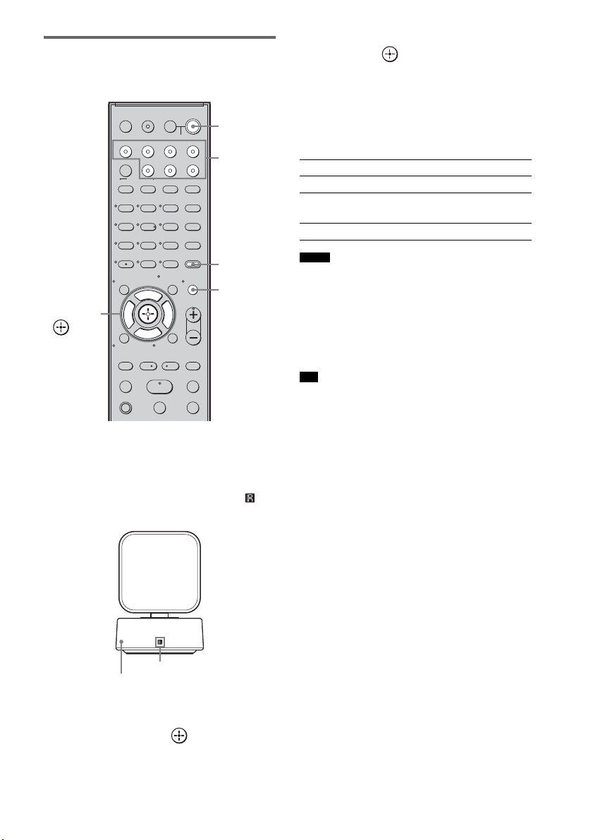
Performing the Auto
Calibration
1 Press ?/1.
The system turns on.
2 Press AMP MENU.
Point the remote at the remote sensor ( ) on
the remote commander receiver.
3 Press x/X repeatedly until “A. CAL
MENU” appears on the top panel
display, then press or c.
4 Press x/X to select “A. CAL START,”
then press .
The Auto Calibration starts after the
countdown.
The measurement process will take
approximately 30 seconds to complete.
The table below shows the display when
measurement starts.
• If “PHONES” appears, you cannot perform the Auto
Calibration. Disconnect the headphones from the S-
AIR product you are using, then restart the Auto
Calibration.
• If “CHECK MIC” appears, you cannot perform the
Auto Calibration. Connect the calibration mic, then
restart the Auto Calibration.
• When the Auto Calibration starts:
– Stand some distance from the speakers and the
listening position to avoid measurement failure. This
is because test signals are output from the speakers
during measurement.
– Avoid making noise to get a more accurate
measurement.
To cancel the Auto Calibration
The Auto Calibration function will be canceled
when you do the following during the
measurement process:
– Press MUTING.
– Press input buttons on the remote or INPUT
SELECTOR on the subwoofer.
– Change the volume level.
123
46
78
0
ENTER
9
TV INPUTTHEATER
TV
?/1
AV
?/1
TV BD DVD SAT
TOP MENU MENU
BD/DVD
RETURN/EXIT
TV
REPLAY ADVANCE
F1 F2
AMP MENU
CLEAR
DISPLAY
MUTING
TONE
TUNING - TUNING +
NIGHT
MODE
GUIDE
FAVORITEWIDEPICTUREJUMP
DMPORTTUNER/BANDVIDEO
SOUND FIELD
?/1
TV CH -
PRESET -
TV CH +
PRESET +
F
Gg
f
.
HmM
Xx
<
<
>
5
SYSTEM STANDBY
MENU/HOME
TOOLS/
OPTIONS
TV VOL
MASTER VOL
C, X, x, c,
?/1
AMP
MENU
Input
buttons
MUTING
Remote sensor
Remote commander receiver
Measurement for Display
Speaker existance TONE
Speaker gain, distance, frequency
response
T.S.P.
Subwoofer gain and distance SUBWOOFER
Notes
Tip
27
US
Getting Started
Confirming/saving the
measurement result
1 Confirm the measurement result.
When the measurement ends, a beep sounds
and the measurement result appears on the
top panel display.
• After “SAVE EXIT” is displayed for 50 seconds, the
measurement result is saved automatically, without
the need to saving procedure.
2 Press x/X repeatedly to select the
desired item, then press or c. To
return, press C or RETURN.
3 Save the measurement result.
Select “SAVE EXIT” in step 2, then press
.
The measurement result is saved.
When error codes appear
Try the remedies and perform the Auto
Calibration again.
When you select “WRN CHECK”
If a warning on the measurement result is
present, detailed information is displayed.
Item Explanation
SAVE EXIT Saves the measurement result
and exits the setting process.
WRN CHECK Displays warning concerning
the measurement result. See
“When you select “WRN
CHECK”” (page 27).
DIST INFO Displays the measurement
result for speaker distance.
LEVEL INFO Displays the measurement
result for speaker level.
EXIT Exits the setting process
without saving the
measurement result.
Note
Item Explanation
ERROR 32 • The sound input from the
calibration mic is out of the
acceptable range.
• The calibration mic or
subwoofer may be damaged.
Contact your Sony dealer or
local authorized Sony service
facility.
ERROR F 33 The front speakers are not
connected.
Check that the front speakers
are connected properly.
ERROR SR 33 Either the surround left or
surround right speaker is not
connected.
Check that the surround
speakers are connected
properly.
ERROR SW 33 The subwoofer may be
damaged.
Contact your Sony dealer or
local authorized Sony service
facility.
Warning code Explanation
WARNING 40 The Auto Calibration has
completed. However, the noise
level is high. You may be able
to perform the Auto Calibration
properly if you try it again, even
though the measurement cannot
be performed in all
environments. Try to perform
the Auto Calibration in a quiet
environment.
WARNING 41
WARNING 42
The sound input from the
calibration mic is out of the
acceptable range. The distance
between the calibration mic and
the speakers is too closed. Set
them away, and then try to
perform the Auto Calibration.
WARNING 43 The distance and position of the
subwoofer cannot be detected.
This may be caused by noise.
Try to perform the Auto
Calibration in a quiet
environment.
NO WARNING There is no warning
information.
Item Explanation
continued

28
US
When you select “DIST INFO” or
“LEVEL INFO”
You can check the speaker distance or speaker
level.
• The measurement result of a speaker will not appear if
the subwoofer does not recognize that the speaker is
connected.
After you have finished
Disconnect the calibration mic from the
subwoofer.
• If you have changed the position of the speakers, Sony
recommends that you perform the Auto Calibration
again in order to enjoy the surround sound.
Deleting the result of the Auto
Calibration
You can delete the result of the Auto Calibration.
If there is no saved data, you cannot delete the
result.
1 Press AMP MENU.
2 Press x/X repeatedly until “A.CAL
MENU” appears, then press or c.
3 Press x/X repeatedly to select “A.CAL
CLEAR,” then press or c.
4 Press x/X to select “YES,” then press
.
The saved result is deleted.
The settings for speaker distance and
speaker level return to their defaults.
Depending on the audio output settings of the
connected component, the sound may output in 2
channel sound format only. In this case, set the
connected component to output the sound in
multi channel sound format (PCM, DTS, Dolby
Digital). For details on audio output settings,
refer to the operating instructions of the
connected component.
Note
Note
Setting up the Sound
Output of the Connected
Component
29
US
Getting Started
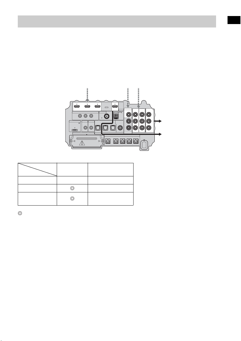
The subwoofer is equipped with a function for converting video signals.
Video signals and component video signals can be output as HDMI video signals and these up-
converted video signals can only be output from the HDMI TV OUT jack. See the illustration that
follows.
In the video input/output conversion table of the subwoofer
: Video signals are up-converted and output through the video converter.
a : The same type of signal as that of the input signal is output. Video signals are not up-converted.
X : Video signals are not output.
Notes on converting video signals
• When video signals from a VCR, etc., are converted on the subwoofer and then output to your TV,
depending on the status of the video signal output, the image on the TV screen may appear distorted
horizontally, or no image may be output.
• HDMI video signals cannot be converted to component video signals.
• The up-converted video signals are output only from the HDMI OUT jack. They are not output from
any other video jacks.
• When you play back a VCR with an image improvement circuit, such as TBC, the images may be
distorted or may not be output. In this case, set the image improvement circuit function to off.
Function for Conversion of Video Signals
HDMI TV OUT
COMPONENT VIDEO
MONITOR OUT
HDMI IN A a X
VIDEO IN B X
COMPONENT
VIDEO IN C
a
IR REMOTE
DMPORT
SPEAKER ONLY FOR SS-IS15
ECM-AC2 IR-R100
ANTENNA
IR IN IR OUT1 IR OUT2
FM AM
75
COAXIAL
DC 5V
0.7A MAX
FRONT R FRONT L SUR R SUR LCENTER
AUDI O IN
ASSIGNABLE
L
R
EZW-T100 DIGITAL
TV IN DVD IN SAT IN
OPTICAL
COMPONENT VIDEO
DVD IN SAT IN
MONITOR
OUT
Y
P
B/
C
B
PR/
C
R
SAT IN
ASSIGNABLE
COAXIAL
VIDEO
VIDEO IN
HDMI
BD IN DVD IN SAT IN TV OUT
Input signals
ABC
C
ABC
Output signalsBottom of the
subwoofer
INPUT jack
OUTPUT jack
30
US
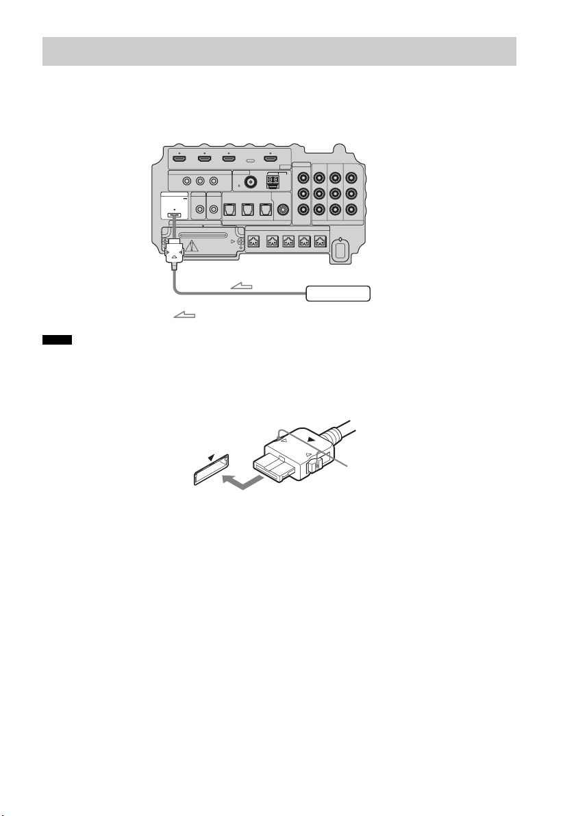
To connect the DIGITAL MEDIA PORT adapter
You can enjoy sound from a component connected to the subwoofer, using the DIGITAL MEDIA
PORT adapter.
• Do not connect or disconnect the DIGITAL MEDIA PORT adapter while the system is turned on.
• When you connect the DIGITAL MEDIA PORT adapter, be sure the connector is inserted with the arrow mark
facing toward the arrow mark on the DMPORT jack. To detach the DIGITAL MEDIA PORT adapter, press and
hold
A and then pull out the connector.
Connecting the Other Components
Notes
IR REMOTE
VIDEO
DMPORT
SPEAKER ONLY FOR SS-IS15
ECM-AC2 IR-R100
ANTENNA
HDMI
IR IN IR OUT1 IR OUT2
FM AM
75
COAXIAL
DC 5V
0.7A MAX
FRONT R FRONT L SUR R SUR LCENTER
BD IN DVD IN SAT IN
SAT IN
ASSIGNABLE
COAXIAL
AUDI O IN
ASSIGNABLE
VIDEO IN
L
R
TV OUT
EZW-T100 DIGITAL
TV IN DVD IN SAT IN
OPTICAL
COMPONENT VIDEO
DVD IN SAT IN
MONITOR
OUT
Y
P
B/
C
B
PR/
C
R
DIGITAL MEDIA PORT adapter
: Signal flow
Bottom of the
subwoofer
A
31
US
Getting Started
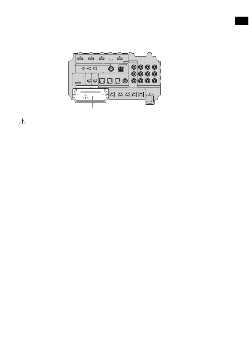
To use the wireless system
The system is compatible with the S-AIR function, which allows sound transmission between the
subwoofer and S-AIR product (not supplied). When you purchase the S-AIR product, you need to
establish sound transmission.
For details, see page 65.
CAUTION
• There is no need to open the slot cover until the S-AIR product is used.
IR REMOTE
VIDEO
DMPORT
SPEAKER ONLY FOR SS-IS15
ECM-AC2 IR-R100
ANTENNA
HDMI
IR IN IR OUT1 IR OUT2
FM AM
75
COAXIAL
DC 5V
0.7A MAX
FRONT R FRONT L SUR R SUR LCENTER
BD IN DVD IN SAT IN
SAT IN
ASSIGNABLE
COAXIAL
AUDI O IN
ASSIGNABLE
VIDEO IN
L
R
TV OUT
EZW-T100 DIGITAL
TV IN DVD IN SAT IN
OPTICAL
COMPONENT VIDEO
DVD IN SAT IN
MONITOR
OUT
Y
P
B/
C
B
PR/
C
R
Slot cover
Bottom of the
subwoofer
32
US
For more information, see the pages indicated in parentheses.
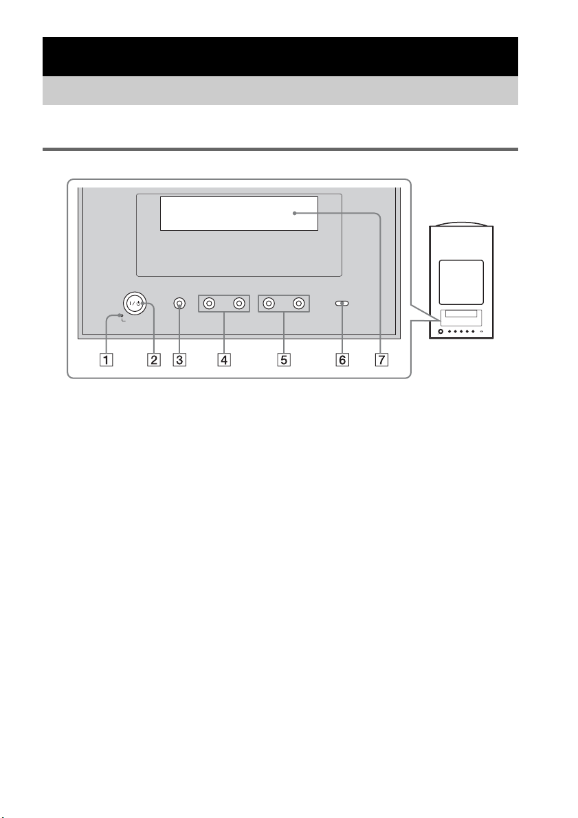
Top panel
A POWER / ACTIVE STANDBY
Green: the system turns on.
Amber: the Control for HDMI function or the S-AIR STANDBY MODE function is working
while the system is turned off.
No light: the system is turned off, and the Control for HDMI function and the S-AIR STANDBY
MODE function is not working.
B ?/1 (on/standby)
Press to turn the system on or off.
C INPUT SELECTOR
Press to select the input source to play back.
D PRESET –/+
Press to go to the previous/next preset radio station.
E VOLUME –/+
Press to adjust the volume level.
F S-AIR
Green: the S-AIR transmitter (not supplied) is inserted in the subwoofer and the system
establishes sound transmission.
No light: the system does not establish sound transmission by the S-AIR function.
G Top panel display
Check the system status.
Playback Options
Index to Parts and Controls
-
VOLUME +
-
PRESET +INPUT SELECTOR
POWER/
ACTIVE STANDBY

33
US
Playback Options
About the indications in the top panel display
A Lights up according to the audio input signals.
B SLEEP (62)
Flashes when the Sleep Timer function is active.
C NIGHT (40)
Lights up when the night mode is on.
D COAX/OPT
Lights up according to the coaxial or optical signal being input.
E TUNED (46)
Lights up when a radio station is received.
F ST/MONO (48)
Lights up according to the stereo or monaural status of the radio.
G Displays system’s status.
Radio frequency, sound field, etc.
H HDMI (16, 74)
Lights up when an HDMI component is being used.
continued
34
US
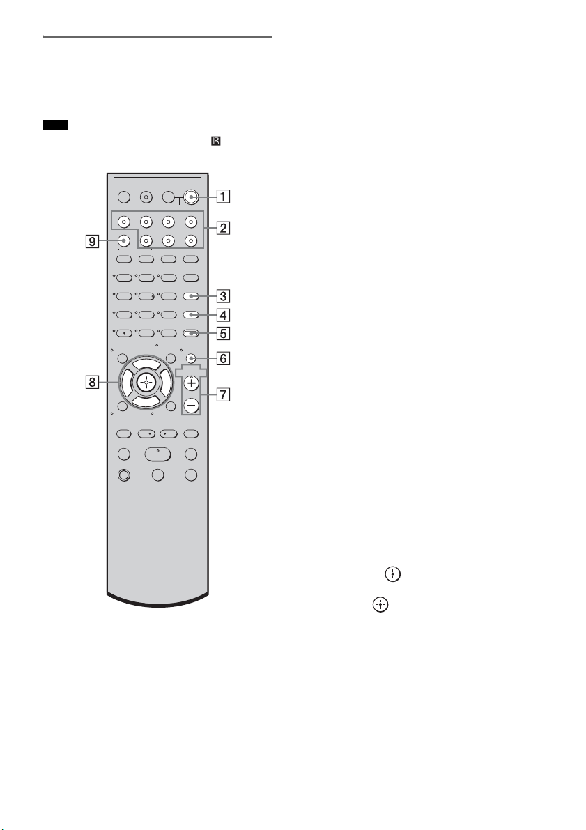
Remote control
Here describes the buttons for amplifier
operation only. See page 50 for the buttons for
operation of the connected components.
• Point the remote at the remote sensor ( ) on the
remote commander receiver.
* The 5, H, and VOL + buttons have a tactile dot.
Use it as a guide during operation.
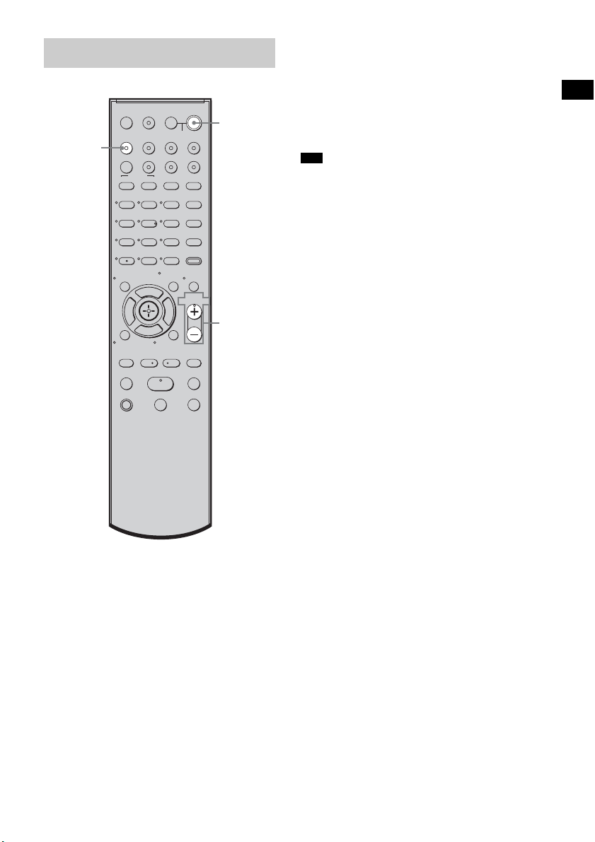
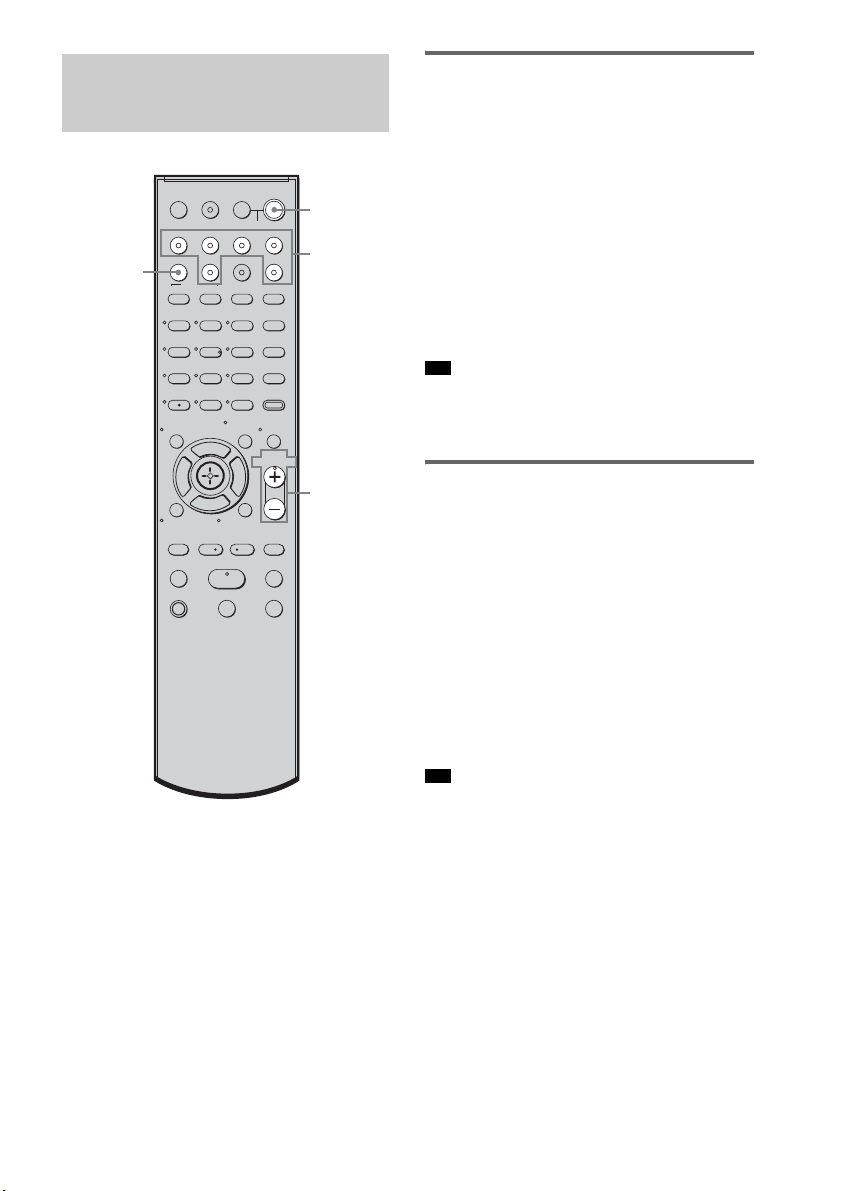
A ?/1 (on/standby)
Press to turn the system on or off.
To save the power in standby mode
Press ?/1 while the system turns on.
To enter power saving mode, make sure that
the system is in the following status.
– “CTRL: HDMI” is set to “CTRL OFF”
(page 41).
– “S-AIR STBY” is set to “STBY OFF”
(page 71).
To cancel standby mode, press
?/1 once.
B Input buttons
Press one of the buttons to select the
component you want to use.
The buttons are factory assigned to control
Sony components. You can change the
factory settings of the input buttons to suit
the components in your system. For details,
see “Changing the Input Button
Assignments of the Remote” (page 52).
C TONE
Press to adjust the bass, middle, and treble
level (page 40).
D NIGHT MODE
Press to enjoy sound effects for watching
movies at night (page 40).
E AMP MENU
Press to display the menu of the system
(page 54).
F MUTING
Press to turn off the sound.
G MASTER VOL +/–
Press to adjust the volume.
H C, X, x, c or
Press C, X, x or c to select the settings.
Then press to enter the selection.
I SOUND FIELD
Press to select the sound field (page 38).
Note
123
46
78
0
ENTER
9
TV INPUTTHEATER
TV
?/1
AV
?/1
TV BD DVD SAT
TOP MENU MENU
BD/DVD
RETURN/EXIT
TV
REPLAY ADVANCE
F1 F2
AMP MENU
CLEAR
DISPLAY
MUTING
TONE
TUNING - TUNING +
NIGHT
MODE
GUIDE
FAVORITEWIDEPICTUREJUMP
DMPORTTUNER/BANDVIDEO
SOUND FIELD
?/1
TV CH -
PRESET -
TV CH +
PRESET +
F
Gg
f
.
HmM
Xx
<
<
>
5
SYSTEM STANDBY
MENU/HOME
TOOLS/
OPTIONS
TV VOL
MASTER VOL
35
US
Playback Options
1 Turn on the TV and choose a program.
For details, refer to the operating
instructions of the TV.
2 Turn the system on.
3 Press TV (white) on the remote.
4 Adjust the volume of the system.
• When you connect a Sony TV, the audio input of the
TV is switched and the image from the TV tuner is
displayed on the TV screen automatically by pressing
the TV (white) button. To change this setting, see
“Changing the Input Button Assignments of the
Remote” (page 52).
• The sound may be output from the TV’s speaker. In
this case, turn the volume of the TV’s speaker down
to the minimum.
Enjoying TV
123
46
78
0
ENTER
9
TV INPUTTHEATER
TV
?/1
AV
?/1
TV BD DVD SAT
TOP MENU MENU
BD/DVD
RETURN/EXIT
TV
REPLAY ADVANCE
F1 F2
AMP MENU
CLEAR
DISPLAY
MUTING
TONE
TUNING - TUNING +
NIGHT
MODE
GUIDE
FAVORITEWIDEPICTUREJUMP
DMPORTTUNER/BANDVIDEO
SOUND FIELD
?/1
TV CH -
PRESET -
TV CH +
PRESET +
F
Gg
f
.
HmM
Xx
<
<
>
5
SYSTEM STANDBY
MENU/HOME
TOOLS/
OPTIONS
TV VOL
MASTER VOL
?/1
MASTER
VOL +/–
TV
(white)
Tips
36
US
Enjoying a satellite tuner
1 Turn on the TV.
For details, refer to the operating
instructions of the TV.
2 Turn the satellite tuner and the system
on.
3 Press SAT on the remote.
4 Change the TV input.
For details, refer to the operating
instructions of the TV.
5 Adjust the volume of the system.
• The sound may be output from the TV’s speaker. In
this case, turn the volume of the TV’s speaker down
to the minimum.
Enjoying Blu-ray Disc, DVD, or
“PlayStation 3”
1 Turn on the TV.
2 Turn the Blu-ray Disc/DVD player
(recorder) or “PlayStation 3” and the
system on.
3 Press DVD or BD on the remote.
4 Change the TV input.
For details, refer to the operating
instructions of the TV.
5 Play back the disc.
• Even if you playback Dolby True HD, Dolby Digital
Plus or DTS-HD with a connected component
compatible with these sound formats, the system
accepts as Dolby Digital or DTS. When you connect
the component to the system using an HDMI cable to
playback these high-quality sound formats, set the
connected component to output the sound in multi
channel PCM, if possible.
Enjoying Other
Components
123
46
78
0
ENTER
9
TV INPUTTHEATER
TV
?/1
AV
?/1
TV BD DVD SAT
TOP MENU MENU
BD/DVD
RETURN/EXIT
TV
REPLAY ADVANCE
F1 F2
AMP MENU
CLEAR
DISPLAY
MUTING
TONE
TUNING - TUNING +
NIGHT
MODE
GUIDE
FAVORITEWIDEPICTUREJUMP
DMPORTTUNER/BANDVIDEO
SOUND FIELD
?/1
TV CH -
PRESET -
TV CH +
PRESET +
F
Gg
f
.
HmM
Xx
<
<
>
5
SYSTEM STANDBY
MENU/HOME
TOOLS/
OPTIONS
TV VOL
MASTER VOL
?/1
MASTER
VOL +/–
Input
buttons
SOUND
FIELD
Tip
Tip

37
US
Playback Options
Enjoying a VCR
1 Turn on the TV.
2 Turn the VCR player and the system on.
3 Press VIDEO on the remote.
4 Change the TV input.
For details, refer to the operating
instructions of the TV.
5 Play back the tape on the VCR.
Enjoying a connected
component through DMPORT
connection
1 Press DMPORT on the remote.
2 Start playback of the connected
component.
• When listening to MP3 or other compressed music
files using a portable audio source, you can enhance
the sound. Press SOUND FIELD repeatedly until “P.
AUDIO” appears in the top panel display.
Tip
38
US
Selecting the sound field
This system can create multi channel surround
sound. You can select one of the optimized
sound fields from the system’s preprogrammed
sound fields.
Enjoying Surround Sound
Using Sound Field
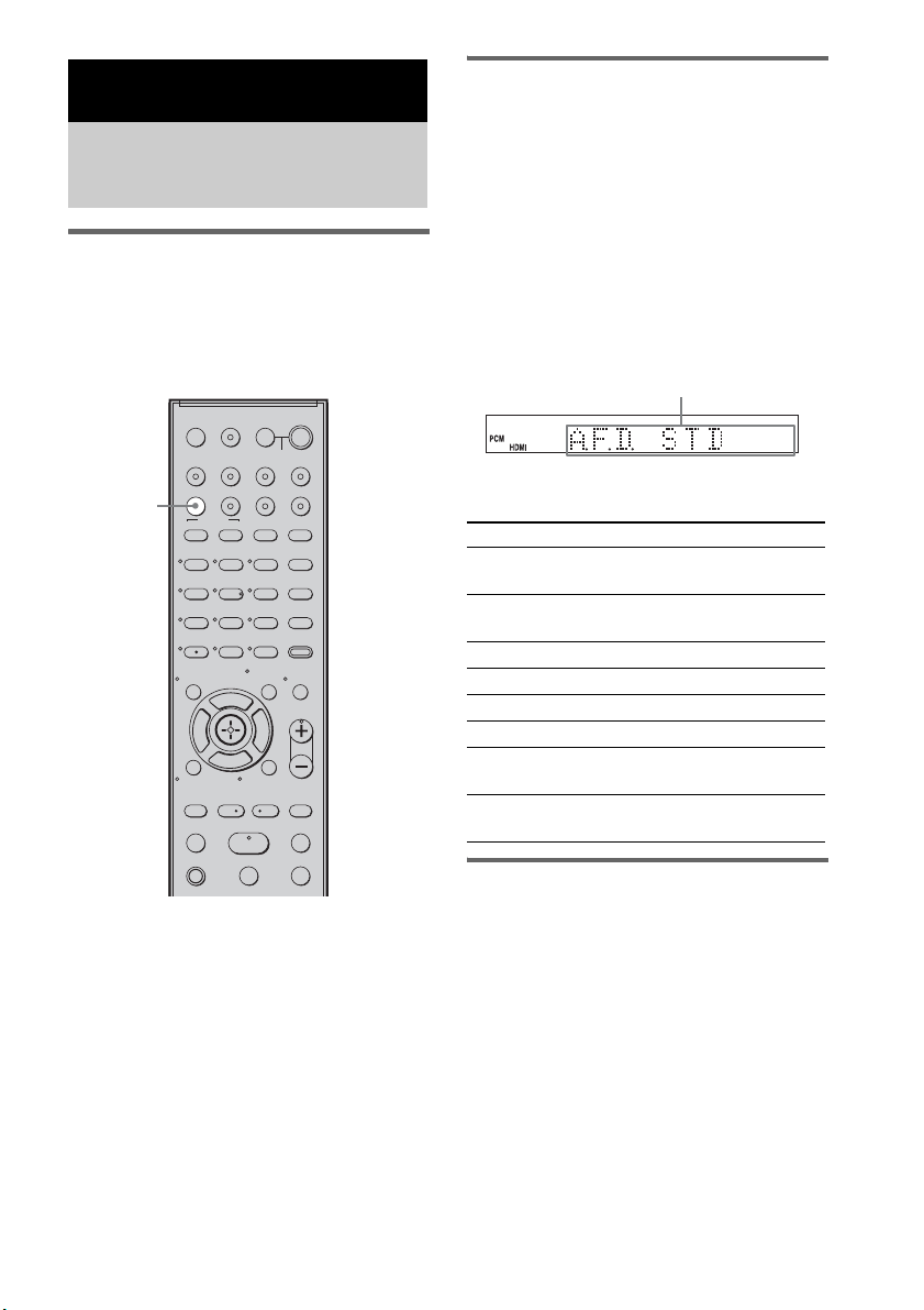
Press SOUND FIELD.
The present sound field appears.
Each time you press the SOUND FIELD button,
the display changes cyclically as follows:
A.F.D. STD t A.F.D. MULTI t
PLII MOVIE t PLII MUSIC t SPORTS t
NEWS t P. AUDIO t OMNI-DIR t
A.F.D. STD t ...
Press SOUND FIELD repeatedly until the sound
field you want appears.
Available sound fields
Automatic outputting of the
original sound
x AUTO FORMAT DIRECT STANDARD
The auto decoding function automatically
detects the type of audio signal being input
(Dolby Digital, DTS, or standard 2 channel
stereo) and performs the proper decoding if
necessary. This mode presents the sound as it
was recorded/encoded, without adding any
effects (e.g. reverberation).
However, if there are no low frequency signals
(Dolby Digital LFE, etc.), it will generate a low
frequency signal for output to the subwoofer.
Surround Functions
Enjoying the Surround
Effects
123
46
78
0
ENTER
9
TV INPUTTHEATER
TV
?/1
AV
?/1
TV BD DVD SAT
TOP MENU MENU
BD/DVD
RETURN/EXIT
TV
REPLAY ADVANCE
F1 F2
AMP MENU
CLEAR
DISPLAY
MUTING
TONE
TUNING - TUNING +
NIGHT
MODE
GUIDE
FAVORITEWIDEPICTUREJUMP
DMPORTTUNER/BANDVIDEO
SOUND FIELD
?/1
TV CH -
PRESET -
TV CH +
PRESET +
F
Gg
f
.
HmM
Xx
<
<
>
5
SYSTEM STANDBY
MENU/HOME
TOOLS/
OPTIONS
TV VOL
MASTER VOL
SOUND
FIELD
Sound field Display
AUTO FORMAT DIRECT
STANDARD
A.F.D. STD
AUTO FORMAT DIRECT
MULTI
A.F.D. MULTI
Dolby Pro Logic II MOVIE PLII MOVIE
Dolby Pro Logic II MUSIC PLII MUSIC
SPORTS SPORTS
NEWS NEWS
PORTABLE AUDIO
ENHANCER
P. AUDIO
OMNI-DIRECTIONAL
SOUND
OMNI-DIR
Display area

39
US
Surround Functions
Outputting the sound from
multiple speakers
x AUTO FORMAT DIRECT MULTI
This mode lets you enjoy audio playback of all
types of discs from multiple speakers.
• The sound is not output from multiple speakers
depending on the source.
• Depending on the disc or source, the beginning of the
sound may be cut off as the optimum mode is
automatically selected. To avoid cutting the sound,
select “A.F.D. STD.”
Outputting 2 channel sources
like CDs by 5.1channel
x Dolby Pro Logic II MOVIE/MUSIC
Dolby Pro Logic II produces five full-bandwidth
output channels from 2 channel sources. This is
done using an advanced, high-purity matrix
surround decoder that extracts the spatial
properties of the original recording without
adding any new sounds or tonal colorations.
• When the input signal is multi channel source, Dolby
Pro Logic II MOVIE/MUSIC are canceled and the
multi channel source is output directly.
• When the bilingual broadcast sound is input, Dolby
Pro Logic II MOVIE/MUSIC are not effective.
Enjoying the sound effects
x SPORTS
This mode produces clear play-by-play
commentary and realistic sound with surround
effects, such as cheering, etc.
x NEWS
This mode produces the clear announcer’s voice.
x PORTABLE AUDIO ENHANCER
This mode reproduces a clear enhanced sound
image from your portable audio device. This
mode is ideal for MP3 and other compressed
music.
• Multi channel Linear PCM is not available for “P.
AUDIO.”
x OMNI-DIRECTIONAL SOUND
This mode reproduces the stereo effect
everywhere surrounding by five satellite
speakers.
To turn the surround effect off
Press SOUND FIELD repeatedly until “A.F.D.
STD” appears in the top panel display.
• The sound fields memorized for each input are
retained even if you disconnect the AC power cord
(mains lead).
Whenever you select a function such as “DVD” or
“TUNER,” the sound field that was last applied to
function is automatically applied again. For example,
if you listen to DVD with Dolby Pro Logic II MOVIE
as the sound field, then change to another function,
and then return to DVD, Dolby Pro Logic II MOVIE
will be applied again.
Notes
Notes
Note
Tip
40
US
You can adjust the bass, middle, and treble level
easily.
1 Press TONE repeatedly until “BASS,”
“MIDDLE,” or “TREBLE” appears in the
top panel display.
• BASS: adjusts the bass level
(–6.0 – +6.0 dB, 0.5 dB steps).
• MIDDLE: adjusts the middle level
(–6.0 – +6.0 dB, 0.5 dB steps).
• TREBLE: adjusts the treble level
(–6.0 – +6.0 dB, 0.5 dB steps).
2 Press X/x to adjust.
The adjusted value appears in the top panel
display.
3 Press .
• When you use the S-AIR functions with the
headphones, “MIDDLE” appears. However, middle
level is not available for the headphones.
You can enjoy sound effects or dialog, as you
would in a movie theater, even at low volume. It
is useful for watching movies at night.
Press NIGHT MODE.
“NIGHT” lights up in the top panel display and
the sound effect is activated.
To turn off the sound effect
Press NIGHT MODE again.
Adjusting the Bass,
Middle, and Treble Level
Notes
123
46
78
0
ENTER
9
TV INPUTTHEATER
TV
?/1
AV
?/1
TV BD DVD SAT
TOP MENU MENU
BD/DVD
RETURN/EXIT
TV
REPLAY ADVANCE
F1 F2
AMP MENU
CLEAR
DISPLAY
MUTING
TONE
TUNING - TUNING +
NIGHT
MODE
GUIDE
FAVORITEWIDEPICTUREJUMP
DMPORTTUNER/BANDVIDEO
SOUND FIELD
?/1
TV CH -
PRESET -
TV CH +
PRESET +
F
Gg
f
.
HmM
Xx
<
<
>
5
SYSTEM STANDBY
MENU/HOME
TOOLS/
OPTIONS
TV VOL
MASTER VOL
TONE
X, x,
Enjoying the Movies at
Night
123
46
78
0
ENTER
9
TV INPUTTHEATER
TV
?/1
AV
?/1
TV BD DVD SAT
TOP MENU MENU
BD/DVD
RETURN/EXIT
TV
REPLAY ADVANCE
F1 F2
AMP MENU
CLEAR
DISPLAY
MUTING
TONE
TUNING - TUNING +
NIGHT
MODE
GUIDE
FAVORITEWIDEPICTUREJUMP
DMPORTTUNER/BANDVIDEO
SOUND FIELD
?/1
TV CH -
PRESET -
TV CH +
PRESET +
F
Gg
f
.
HmM
Xx
<
<
>
5
SYSTEM STANDBY
MENU/HOME
TOOLS/
OPTIONS
TV VOL
MASTER VOL
NIGHT
MODE
41
US
“BRAVIA” Sync features
By connecting Sony components that are
compatible with the “BRAVIA” Sync with an
HDMI cable (not supplied), operation is
simplified as below:
• One-Touch Play: When you play back a
component such as a Blu-ray Disc/DVD player
(recorder), the system and the TV are turned on
automatically and switch to the appropriate
HDMI input.
• System Audio Control: While watching TV,
you can select to output the sound from the TV
speaker or the speakers of the system.
• System Power Off: When you turn off the TV,
the system and the connected components are
also turned off simultaneously.
“BRAVIA” Sync is compatible with a Sony TV,
Blu-ray Disc/DVD player, AV amplifier, etc.,
with the Control for HDMI function.
Control for HDMI is a mutual control function
standard used by CEC (Consumer Electronics
Control) for HDMI (High-Definition
Multimedia Interface).
The Control for HDMI function will
not operate in the following
cases:
• When you connect this system to a component
which does not correspond with the Control for
HDMI function.
• When you connect the system and components
using other than HDMI connection.
Sony recommends that you connect this system
to products featuring “BRAVIA” Sync.
• Depending on the connected component, the Control
for HDMI function may not work. For details, refer to
the operating instructions of the component.
To use the “BRAVIA” Sync, set the Control for
HDMI function to on for the system and the
connected component.
When you connect a Sony TV with the Control
for HDMI function, the Control for HDMI
function for the system and the connected
component can be set simultaneously by setting
the Control for HDMI function of the TV.
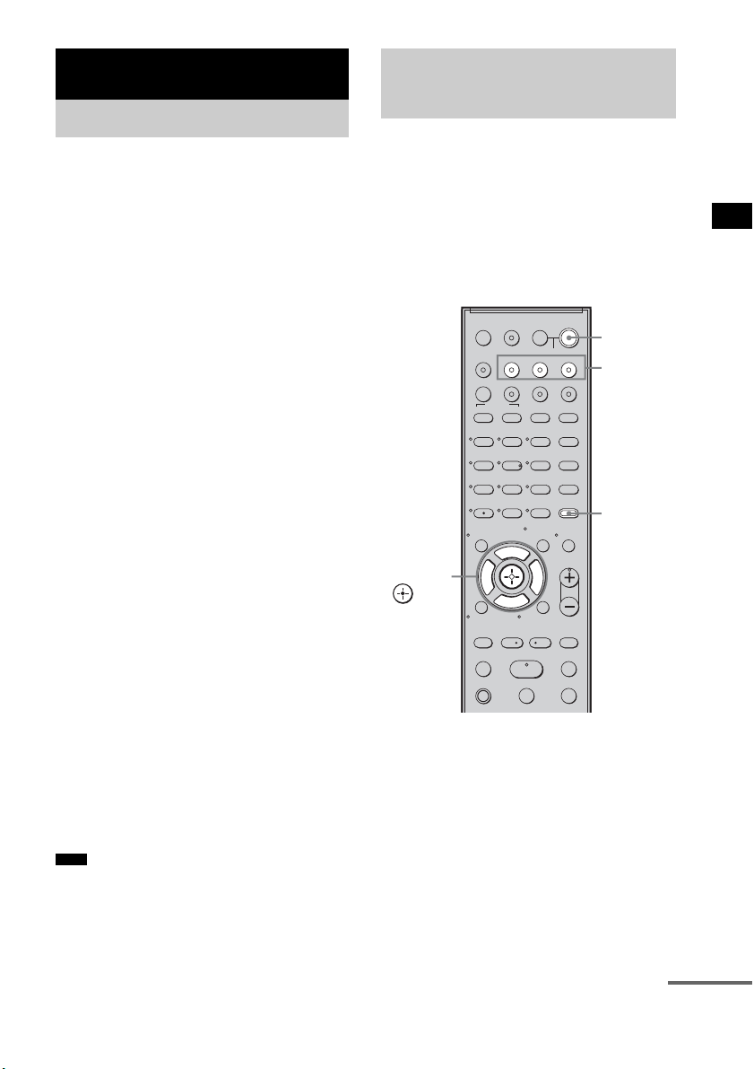
1 Make sure that the system is connected
to the TV and the connected
components (which should be
compatible with the Control for HDMI
function) using HDMI cables (not
supplied).
2 Turn on the system, the TV, and the
connected components.
“BRAVIA” Sync features
What is “BRAVIA” Sync?
Note
Preparing for the
“BRAVIA” Sync
123
46
78
0
ENTER
9
TV INPUTTHEATER
TV
?/1
AV
?/1
TV BD DVD SAT
TOP MENU MENU
BD/DVD
RETURN/EXIT
TV
REPLAY ADVANCE
F1 F2
AMP MENU
CLEAR
DISPLAY
MUTING
TONE
TUNING - TUNING +
NIGHT
MODE
GUIDE
FAVORITEWIDEPICTUREJUMP
DMPORTTUNER/BANDVIDEO
SOUND FIELD
?/1
TV CH -
PRESET -
TV CH +
PRESET +
F
Gg
f
.
HmM
Xx
<
<
>
5
SYSTEM STANDBY
MENU/HOME
TOOLS/
OPTIONS
TV VOL
MASTER VOL
?/1
AMP
MENU
Input
buttons
C, X, x, c,
continued

42
US
3 Select the input of the system
connected to the component you want
to watch (BD, DVD, SAT), and switch
the HDMI input of the TV, so that an
image from the connected component
is displayed.
4 Set the Control for HDMI function of the
TV to on.
The Control for HDMI function for the
system and the connected component is
simultaneously set to on.
During the setting, “SCANNING” appears
in the top panel display. After you finish the
setting, “COMPLETE” appears in the top
panel display. Wait until the setting is
complete.
If “SCANNING” or “COMPLETE”
does not appear after performing
the steps above
Set the Control for HDMI function to on for the
system and the connected component
individually.
1 Press AMP MENU.
2 Press x/X repeatedly until “SET HDMI”
appears, then press or c.
3 Press x/X repeatedly until “CTRL:
HDMI” appears, then press or c.
4 Press x/X to select “CTRL ON,” then
press or c.
5 Press AMP MENU.
The AMP menu turns off. The Control for
HDMI function is set to on.
6 Set the Control for HDMI function of the
connected component to on.
For details, refer to the operating
instructions of the connected component.
7 Select the input of the system
connected to the component you want
to use the Control for HDMI function for
(BD, DVD, SAT), and repeat step 6.
If you add or reconnect the
component
Perform steps of “Preparing for the “BRAVIA”
Sync” and “If “SCANNING” or “COMPLETE”
does not appear after performing the steps
above” again.
• During the setting of the Control for HDMI function
for the system, the System Audio Control function
does not work.
• If the Control for HDMI function for the connected
component cannot be set simultaneously by setting
“Control for HDMI” of the TV, set the Control for
HDMI function using the menu of the connected
component.
• For details on setting the TV and the connected
components, refer to their operating instructions.
• The default setting of the Control for HDMI function
of the system is “OFF.”
Notes
Tip
43
US
“BRAVIA” Sync features
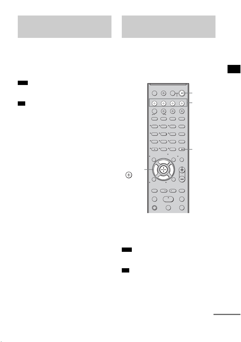
Play back a connected component.
The system and the TV are turned on
automatically and switch to the appropriate
HDMI input.
• Depending on the TV, the start of the content may not
be output.
• You can enjoy the Blu-ray Disc/DVD player
(recorder) connected to the system, even if you turn
the system off. The POWER / ACTIVE STANDBY
indicator lights up in amber at this time.
You can enjoy the TV sound from the speakers
of the system by means of a simple operation.
For details, refer to the operating instructions of
the TV.
Press ?/1 to turn on the system.
The sound is output from the speakers of the
system. The sound is output from the TV's
speaker when you turn the system off.
• When the TV is turned on before this system is turned
on, the TV sound will not be output for a moment.
• You can adjust the volume and turn off the sound of
the system using the TV remote.
Enjoying a Blu-ray Disc/
DVD
(One-Touch Play)
Note
Tip
Enjoying the TV sound
from the Speakers
(System Audio Control)
Note
Tip
123
46
78
0
ENTER
9
TV INPUTTHEATER
TV
?/1
AV
?/1
TV BD DVD SAT
TOP MENU MENU
BD/DVD
RETURN/EXIT
TV
REPLAY ADVANCE
F1 F2
AMP MENU
CLEAR
DISPLAY
MUTING
TONE
TUNING - TUNING +
NIGHT
MODE
GUIDE
FAVORITEWIDEPICTUREJUMP
DMPORTTUNER/BANDVIDEO
SOUND FIELD
?/1
TV CH -
PRESET -
TV CH +
PRESET +
F
Gg
f
.
HmM
Xx
<
<
>
5
SYSTEM STANDBY
MENU/HOME
TOOLS/
OPTIONS
TV VOL
MASTER VOL
?/1
AMP
MENU
Input
buttons
C, X, x, c,
continued

44
US
Using the Volume Limit
function
When the System Audio Control function is
active, and the output method changes from the
TV speaker to the system speaker automatically,
loud sound may be output depending on the
volume level of the system. You can prevent this
by limiting the maximum volume level.
1 Press AMP MENU.
2 Press x/X repeatedly until “SET HDMI”
appears, then press or c.
3 Press x/X repeatedly until “VOL LIMIT”
appears, then press or c.
4 Press x/X to select the maximum
volume level you want.
The maximum volume level changes as
follows:
5 Press AMP MENU.
The AMP menu turns off.
• This function is available only when the Control for
HDMI function is set to on.
• This function is not available when the output method
changes from the system speaker to the TV speaker.
• Sony recommends that you set the maximum volume
level to a little lower than the volume you usually
listen to.
• Regardless of the maximum volume level you set, the
VOLUME +/– button of the subwoofer and the
MASTER VOL +/– button of the remote are operable.
• If you do not want to limit the maximum volume
level, select “MAX.”
Using the input buttons of the
remote
The input buttons (TV (white), BD, DVD, SAT,
VIDEO, DMPORT) work as follows when the
Control for HDMI function is set to on.
• BD, DVD, SAT, VIDEO, DMPORT: Since the
input of the TV is also switched automatically,
you can watch the image of the selected
component on the TV simply by pressing the
buttons.
• TV: The input of the TV switches
automatically. When you connect a Sony TV,
you can watch the TV simply by pressing the
button.
• You can control connected Sony components by
pressing the input buttons. For details, see
“Controlling the Connected Sony Components with
the Remote” (page 50).
Notes
Tips
MAX y 49 y 48 y
...... y 2 y 1 y MIN
Tip
45
US
“BRAVIA” Sync features
When you turn the TV off by using the power
button on the TV’s remote, the system and the
connected components turn off automatically.
Also, when you turn the TV off by using the
system’s remote, the system and the connected
components turn off automatically.
Hold down TV (orange), and press AV
?/1.
The TV, the system, and the connected
components are turned off.
• Depending on the status, the connected components
may not be turned off. For details, refer to the
operating instructions of the connected components.
Turning off the TV,
System, and Connected
Components
(System Power Off)
Note
123
46
78
0
ENTER
9
TV INPUTTHEATER
TV
?/1
AV
?/1
TV BD DVD SAT
TOP MENU MENU
BD/DVD
RETURN/EXIT
TV
REPLAY ADVANCE
F1 F2
AMP MENU
CLEAR
DISPLAY
MUTING
TONE
TUNING - TUNING +
NIGHT
MODE
GUIDE
FAVORITEWIDEPICTUREJUMP
DMPORTTUNER/BANDVIDEO
SOUND FIELD
?/1
TV CH -
PRESET -
TV CH +
PRESET +
F
Gg
f
.
HmM
Xx
<
<
>
5
SYSTEM STANDBY
MENU/HOME
TOOLS/
OPTIONS
TV VOL
MASTER VOL
AV ?/1
TV
(orange)
46
US
You can preset 20 FM stations, and 10 AM
stations. Before tuning, make sure to turn the
volume down to minimum.
1 Press TUNER/BAND.
You can change “FM” or “AM” by pressing
TUNER/BAND.
2 Press and hold TUNING + or – until the
auto scanning starts.
Scanning stops when the system tunes in a
station. “TUNED” and “ST” (for stereo
program) light up in the top panel display.
3 Press MENU.
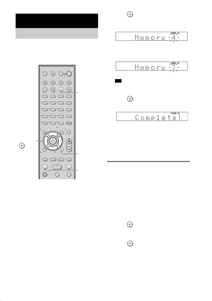
4 Press X/x repeatedly until “Memory?”
appears in the top panel display.
5 Press .
A preset number appears in the top panel
display.
6 Press X/x to select the preset number
you want.
• You can select the preset number directly by
pressing the number buttons.
7 Press .
The station is stored.
8 Press MENU.
9 Repeat 2 to 8 to store other stations.
To change the preset number
Restart from step 3.
Changing the AM tuning
interval
The AM tuning interval can be set to either 10
kHz or 9 kHz.
1 Press TUNER/BAND repeatedly until
“AM” appears in the top panel display.
2 Press MENU.
3 Press X/x repeatedly until “AM Step?”
appears in the top panel display, then
press or
c.
“9k t 10k” or “10k t 9k” appears in the
top panel display.
4 Press .
“Complete!” appears in the top panel
display. The AM tuning interval is changed.
5 Press MENU.
Tuner Functions
Presetting Radio Stations
123
46
78
0
ENTER
9
TV INPUTTHEATER
TV
?/1
AV
?/1
TV BD DVD SAT
TOP MENU MENU
BD/DVD
RETURN/EXIT
TV
REPLAY ADVANCE
F1 F2
AMP MENU
CLEAR
DISPLAY
MUTING
TONE
TUNING - TUNING +
NIGHT
MODE
GUIDE
FAVORITEWIDEPICTUREJUMP
DMPORTTUNER/BANDVIDEO
SOUND FIELD
?/1
TV CH -
PRESET -
TV CH +
PRESET +
F
Gg
f
.
HmM
Xx
<
<
>
5
SYSTEM STANDBY
MENU/HOME
TOOLS/
OPTIONS
TV VOL
MASTER VOL
C, X, x, c,
TUNING
–/+
TUNER/
BAND
MENU
Tip
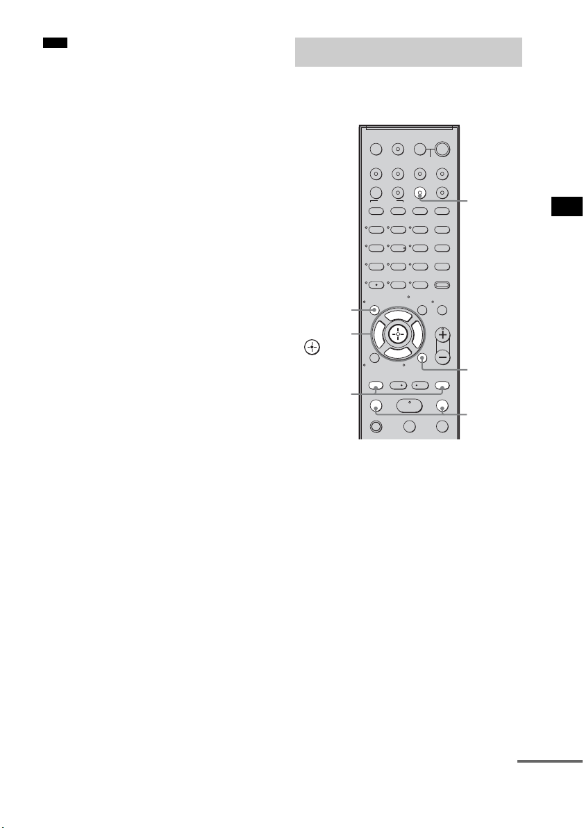
47
US
Tuner Functions
• If you change the interval, AM preset stations will be
erased.
Preset radio stations in the system’s memory first
(see “Presetting Radio Stations” (page 46)).
1 Press TUNER/BAND.
The last received station is tuned in.
You can change “FM” or “AM” by pressing
TUNER/BAND.
2 Press PRESET + or – repeatedly to
select the preset station.
Each time you press the button, the system
tunes in one preset station.
You can select the preset number directly by
pressing the number buttons.
3 Adjust the volume of the system.
To turn off the radio
Press "/1 to turn off the system, or change to
another function.
Note
Listening to the Radio
123
46
78
0
ENTER
9
TV INPUTTHEATER
TV
?/1
AV
?/1
TV BD DVD SAT
TOP MENU MENU
BD/DVD
RETURN/EXIT
TV
REPLAY ADVANCE
F1 F2
AMP MENU
CLEAR
DISPLAY
MUTING
TONE
TUNING - TUNING +
NIGHT
MODE
GUIDE
FAVORITEWIDEPICTUREJUMP
DMPORTTUNER/BANDVIDEO
SOUND FIELD
?/1
TV CH -
PRESET -
TV CH +
PRESET +
F
Gg
f
.
HmM
Xx
<
<
>
5
SYSTEM STANDBY
MENU/HOME
TOOLS/
OPTIONS
TV VOL
MASTER VOL
C, X, x, c,
TUNING
–/+
TUNER/
BAND
MENU
PRESET
–/+
DISPLAY
continued
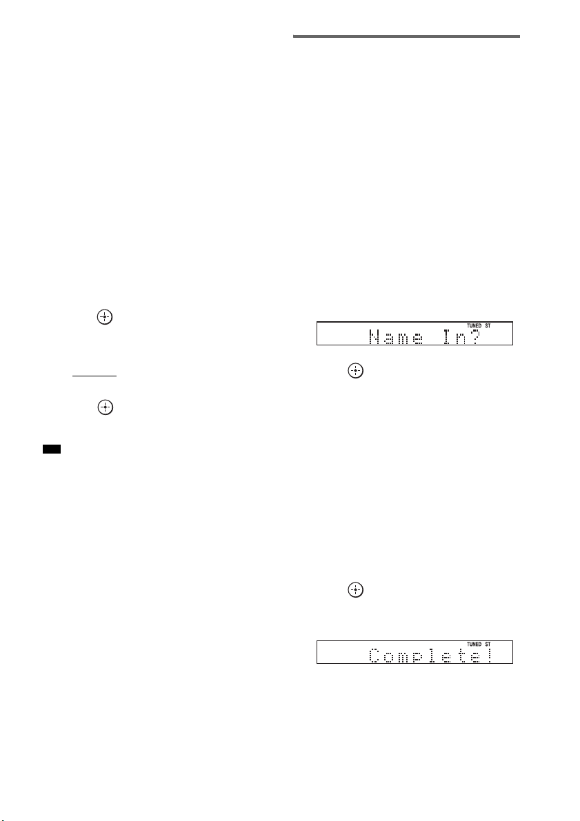
48
US
To listen to non-preset radio
stations
Use manual or automatic tuning in step 2.
For manual tuning, press TUNING + or –
repeatedly.
For automatic tuning, press and hold TUNING +
or –. The automatic tuning stops automatically
when the system receives a radio station. To stop
the automatic tuning manually, press TUNING +
or –.
If an FM program is noisy
If an FM program is noisy, you can select
monaural reception. There will be no stereo
effect, but reception will improve.
1 Press MENU.
2 Press X/x repeatedly until “FM Mode?”
appears in the top panel display, then
press or c.
3 Press X/x to select “MONO.”
The default setting is underlined.
•STEREO
: stereo reception.
• MONO: monaural reception.
4 Press .
5 Press MENU.
• To improve reception, reorient the supplied antennas
(aerials).
Naming preset stations
You can enter a name for preset stations. These
names (for example, “XYZ”) appear in the top
panel display when a station is selected.
Note that no more than one name can be entered
for each preset station.
1 Press TUNER/BAND.
The last received station is tuned in.
You can change “FM” or “AM” by pressing
TUNER/BAND.
2 Press PRESET + or – repeatedly to
select the preset station you want to
create an index name for.
3 Press MENU.
4 Press X/x repeatedly until “Name In?”
appears in the top panel display.
5 Press .
6 Create a name by using C/X/x/c.
Press X/x to select a character, then press c
to move the cursor to the next position.
Letters, numbers, and other symbols can be
input for a radio station name.
If you enter a wrong character
Press C/c repeatedly until the character to
be changed flashes, then press X/x to select
the desired character.
To erase the character, press C/c repeatedly
until the character to be erased flashes, then
press CLEAR.
7 Press .
“Complete!” appears in the top panel
display, and the station name is stored.
8 Press MENU.
Tip

49
US
Tuner Functions
• You can check the frequency in the top panel display
by pressing DISPLAY repeatedly (page 49).
Viewing the station name or
frequency in the top panel
display
When the system is set to “FM” or “AM,” you
can check the frequency using the top panel
display.
Press DISPLAY.
Each time you press DISPLAY, the top panel
display changes as shown.
1 Station name*
2 Frequency**
* This is displayed if you have entered a name for a
preset station.
** Returns to the original display when several seconds
have elapsed.
Tip

50
US
You can control connected Sony components
with the remote of this system.
Some functions cannot be selected depending on
the component. In that case, select them using
the remote control of the component.
* The 5, H, and MASTER VOL + buttons have a
tactile dot. Use it as a guide during operation.
To control the component
1 Press one of the input buttons 3 (TV,
BD, DVD, or SAT) to select the
component you want to operate.
The component assigned to the selected
input button becomes operable.
2 Referring to the following table, press
the corresponding button for the
operation.
Common operations
To control the TV
Press and hold qh TV (orange) button while
pressing the buttons with an orange dot or orange
printing to control the TV.
Advanced Settings
Controlling the Connected
Sony Components with the
Remote
123
46
78
0
ENTER
9
TV INPUTTHEATER
TV
?/1
AV
?/1
TV BD DVD SAT
TOP MENU MENU
BD/DVD
RETURN/EXIT
TV
REPLAY ADVANCE
F1 F2
AMP MENU
CLEAR
DISPLAY
MUTING
TONE
TUNING - TUNING +
NIGHT
MODE
GUIDE
FAVORITEWIDEPICTUREJUMP
DMPORTTUNER/BANDVIDEO
SOUND FIELD
?/1
TV CH -
PRESET -
TV CH +
PRESET +
F
Gg
f
.
HmM
Xx
<
<
>
5
SYSTEM STANDBY
MENU/HOME
TOOLS/
OPTIONS
TV VOL
MASTER VOL
Remote Button Function
2 TV ?/1
AV ?/1
(on/standby)
Turns on or off the Sony
TV or audio/video
components that the
remote is assigned to
operate.
Press 1
?/1 and 2 TV
?/1/AV ?/1 at the same
time to turn off the system
and all other components
that the remote is assigned
to operate (SYSTEM
STANDBY).
7 ENTER Enters the selection.
ws Number buttons Selects channels and tracks
directly.
Remote Button Function
4 WIDE Sets to the wide mode.
5 FAVORITE Displays the stored
favorite channel list.
6 GUIDE Displays the guide when
you are watching analog or
digital channels.
8 TOOLS/
OPTIONS
Enables you to access
various viewing options
and change/make
adjustments according to
the source and screen
format.
9 MUTING Turns off the sound.
q; TV VOL +/– Adjusts the volume.
51
US
Advanced Settings
To control the DVD recorder/Blu-
ray Disc recorder
To control the DVD player/Blu-ray
Disc player
qa MENU/HOME Allows you to select
channels or input sources
and change the settings for
your TV.
qd TV CH +/– Selects the next (+) or
previous (–) channel. To
scan quickly through
channels, press and hold
down either +/–.
qk RETURN/EXIT Returns to the previous
screen of any displayed
menu.
ql C, X, x, c, Selects a menu item and
enters the selection.
w; DISPLAY Displays the current
channel number, etc.
wa Selects digital channels
using with the 0-9 and
ENTER buttons. For
example, to enter “2.1”,
press , , and
ENTER.
ws Number buttons Selects channels. Press 7
ENTER to change
channels immediately.
wd JUMP Jumps back and forth
between two channels. The
TV alternates between the
current channel and the last
channel that was selected.
wf PICTURE Displays the available
picture mode.
wg TV INPUT Selects input.
wh THEATER Automatically sets the
optimal picture settings for
watching movies, when
you connect a Sony TV
which is compatible with
the THEATER button.
Also, the audio is
automatically switched to
the audio output of this
system when you connect
the TV and the system with
HDMI connection, and the
Control for HDMI function
is set to on.
Remote Button Function
2 1
Remote Button Function
4 F1 Selects the HDD.
5 F2 Selects the Blu-ray Disc/
DVD.
qa MENU/HOME Displays the MENU.
qs •
, Jumps forward while
viewing recorded
programs.
qd . Skips chapters.
> Skips forward to the next
available chapter.
qf m/M To fast reverse or to fast
forward the disc when
pressed during playback.
qg H (playback)/X
(pause, press again to
resume normal
playback)/x (stop)
Play mode buttons.
qj
< • Jumps backward while
viewing live or recorded
programs.
ql C, X, x, c, Selects a menu item and
enters the selection.
wd BD/DVD
TOP MENU
Displays the top menu/disc
menu.
wf BD/DVD MENU
Remote Button Function
qa MENU/HOME Displays the MENU.
qs •
, Jumps forward.
qd ./> Skips chapters.
qf m/M To fast reverse or to fast
forward the disc when
pressed during playback.
qg H (playback)/X
(pause, press again to
resume normal
playback)/x (stop)
Play mode buttons.
qj
< • Jumps backward.
ql C, X, x, c, Selects a menu item and
enters the selection.
continued
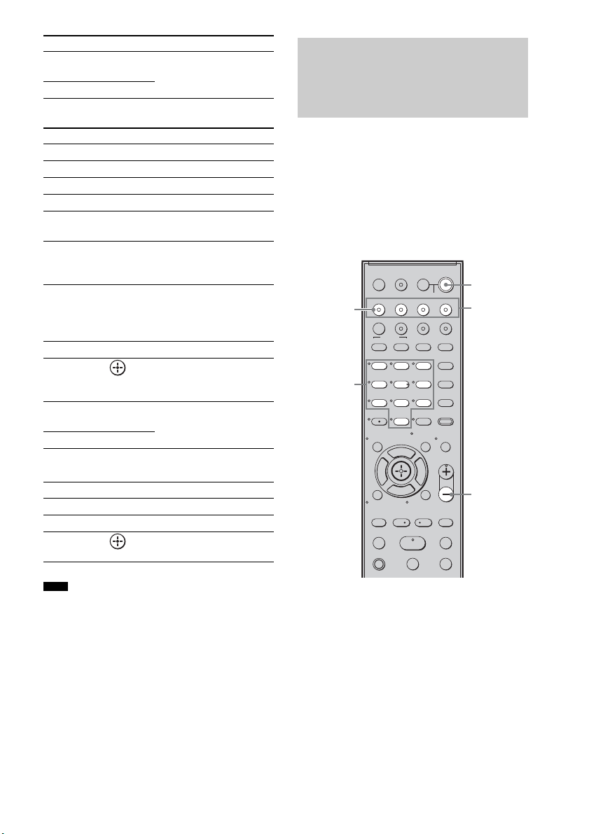
52
US
To control the HDD/DVD COMBO
To control the SAT
• The above explanations are intended to serve as an
example only. Depending on the component, the
above operations may not be possible, or may operate
differently than described.
You can change the factory settings of the input
buttons to suit the components in your system.
For example, if you connect a Blu-ray Disc
player to the DVD jack on the system, you can
set the DVD button on this remote to control the
Blu-ray Disc player.
You cannot assign any component other than a
TV to the TV (white) button of the remote.
1 Hold down the input button you want to
change the assignment of.
Example: Hold down DVD.
2 Referring to the following table, press
the corresponding button for the
category you want.
Example: Press 3.
Now you can use the DVD button to control
the Blu-ray Disc player.
wd BD/DVD
TOP MENU
Displays the top menu/disc
menu.
wf BD/DVD MENU
Remote Button Function
4 F1 Selects the HDD.
5 F2 Selects the DVD.
qa MENU/HOME Displays the MENU.
qs •
, Advance.
qd ./> Specifies the previous/next
chapter/track.
qf m/M To fast reverse or to fast
forward the disc when
pressed during playback.
qg H (playback)/X
(pause, press again to
resume normal
playback)/x (stop)
Play mode buttons.
qj
< • Changes to replay mode.
ql C, X, x, c, Moves the highlight
(cursor) and selects the
item.
wd BD/DVD
TOP MENU
Displays the top menu/disc
menu.
wf BD/DVD MENU
Remote Button Function
6 GUIDE Displays the guide menu.
qa MENU/HOME Displays the MENU.
ql C, X, x, c, Selects a menu item and
enters the selection.
Note
Remote Button Function
Changing the Input Button
Assignments of the
Remote
123
46
78
0
ENTER
9
TV INPUTTHEATER
TV
?/1
AV
?/1
TV BD DVD SAT
TOP MENU MENU
BD/DVD
RETURN/EXIT
TV
REPLAY ADVANCE
F1 F2
AMP MENU
CLEAR
DISPLAY
MUTING
TONE
TUNING - TUNING +
NIGHT
MODE
GUIDE
FAVORITEWIDEPICTUREJUMP
DMPORTTUNER/BANDVIDEO
SOUND FIELD
?/1
TV CH -
PRESET -
TV CH +
PRESET +
F
Gg
f
.
HmM
Xx
<
<
>
5
SYSTEM STANDBY
MENU/HOME
TOOLS/
OPTIONS
TV VOL
MASTER VOL
MASTER
VOL –
Number
buttons
Input
buttons
TV
(white)
?/1

53
US
Advanced Settings
Categories and the
corresponding buttons for BD,
DVD, and SAT
* The default setting of the DVD button.
Sony DVD recorders are operated with a DVD1 or
DVD3 setting. For details, refer to the operating
instructions of the DVD recorders.
** The default setting of the BD button.
For details on the BD1 or BD3 setting, refer to the
operating instructions of the Blu-ray Disc player or
Blu-ray Disc recorder.
*** The default setting of the SAT button.
Categories and the
corresponding buttons for TV
* The default setting of the TV (white) button.
When this setting is selected, the audio input of the
TV is switched and the image from the TV tuner is
displayed on the TV screen automatically by
pressing the TV (white) button.
** When this setting is selected, the audio input of the
TV is switched automatically by pressing the TV
(white) button.
To clear all remote button
assignments
Press and hold MASTER VOL –, ?/1, and then
press TV INPUT. The remote is reset to its
factory settings.
Categories Press
DVD player
(command mode DVD1)*
1
DVD recorder
(command mode DVD3)
2
Blu-ray Disc player
(command mode BD1)**
3
Blu-ray Disc recorder
(command mode BD3)
4
DVR
(Digital CATV terminal)
7
DSS
(Digital Satellite Receiver)***
8
Categories Press
TV* 5
TV** 6
54
US
Using the AMP menu
You can set the following items with AMP
MENU on the remote.
The default settings are underlined.
1)
See ““BRAVIA” Sync features” (page 41).
2)
This setting appears only when “CTRL: HDMI” is
set to “CTRL ON.”
3)
See “Step 6: Calibrating the Appropriate Settings
Automatically” (page 24). “A. CAL CLEAR”
setting appears only when the result of the Auto
Calibration is saved.
4)
This setting is only for the optical and coaxial input
signals.
Settings and Adjustments
Using the Amplifier Menu
CTRL ON
CTRL OFF
CTRL: HDMI
MAX, 49,
48…..2, 1,
MIN
VOL LIMIT
2)
SET
HDMI
1)
FL 10’ 0”
*
(3 m 0 cm)
FL DIST
CENTER YES
CENTER NO
CENTER SPSP
SETUP
SUR YES
SUR NO
SUR SP
CNT 10’ 0”
*
(3 m 0 cm)
CNT DIST
FR 10’ 0”
*
(3 m 0 cm)
FR DIST
SR 10’ 0”
*
(3 m 0 cm)
SR DIST
SL 10’ 0”
*
(3 m 0 cm)
SL DIST
SW 10’ 0”
*
(3 m 0 cm)
SW DIST
FL 0.0
FL LEVEL
T. TONE ON
T. TONE OFF
TEST TONE
LEVEL
CNT 0.0
CNT LEVEL
FR 0.0
FR LEVEL
SR 0.0SR LEVEL
SL 0.0
SL LEVEL
SW 0.0
SW LEVEL
A. CAL START
YES
NO
A. CAL CLEAR
A. CAL
MENU
3)
* For North American models
SYNC OFF,
1, 2, …..20
A/V SYNC
4)
ANALOG VD
ANALOG TV
A. ASSIGN
AUDIO
ANALOG SAT
ANALOG DVD
ANALOG BD
COAX SAT
COAX DVD
D. ASSIGN
MAIN
SUB
DUAL MONO
MAIN+SUB
DRC MAX
DRC STD
AUDIO DRC
DRC OFF
SLEEP OFF, 10M,
20M, …..90M
SLEEP
DIMMER ON
DIMMER OFF
DIMMER
CUST-
OMIZE
DSPL ON
DSPL OFF
DISPLAY
START
CONDITION
PAIRING
S-AIR
SET
5)
S-AIR ID: A
S-AIR ID: B
S-AIR ID
S-AIR ID: C
PARTY
SEPARATE
S-AIR MODE
AUTO
ON
RF CHANGE
OFF
STBY ON
STBY OFF
S-AIR STBY
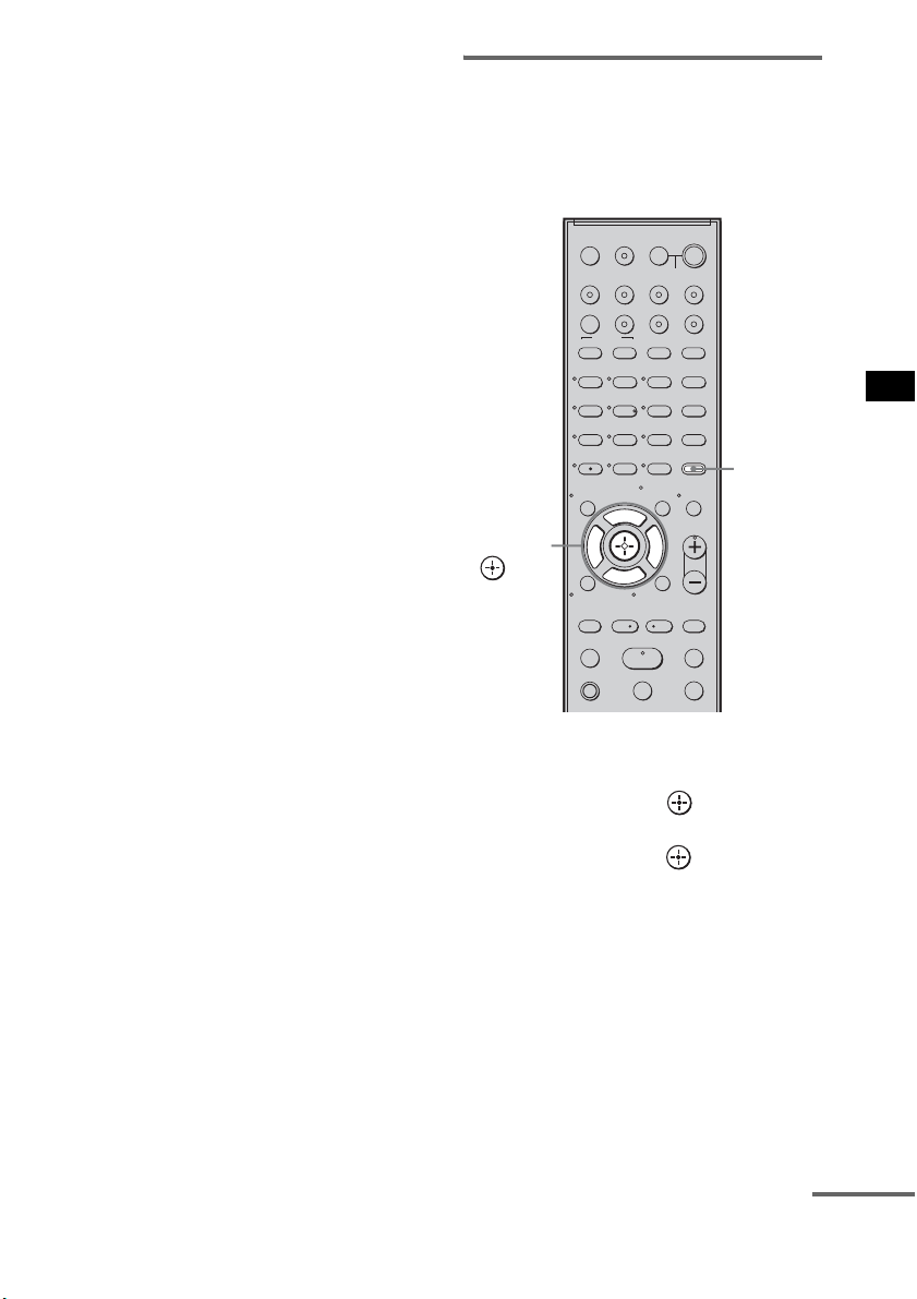
55
US
Advanced Settings
5)
This setting appears only when you insert the S-AIR
transmitter (not supplied).
1 Press AMP MENU to turn on the AMP
menu.
2 Press C/X/x/c repeatedly to select the
item and the setting.
3 Press AMP MENU to turn off the AMP
menu.
The following pages show details for each
setting.
Setting the speaker
connection
To obtain the best possible surround sound, you
can set the connection of the center and surround
speakers.
1 Press AMP MENU.
2 Press x/X repeatedly until “SP SETUP”
appears, then press or c.
3 Press x/X repeatedly to select the
speaker, then press or c.
• CENTER SP: selects the center speaker.
• SUR SP: selects the surround speakers.
4 Press x/X to select the setting.
• CENTER (SUR) YES: selects when you
connect the speaker(s).
• CENTER (SUR) NO: selects when you do
not connect the speaker(s).
5 Press AMP MENU.
The AMP menu turns off.
123
46
78
0
ENTER
9
TV INPUTTHEATER
TV
?/1
AV
?/1
TV BD DVD SAT
TOP MENU MENU
BD/DVD
RETURN/EXIT
TV
REPLAY ADVANCE
F1 F2
AMP MENU
CLEAR
DISPLAY
MUTING
TONE
TUNING - TUNING +
NIGHT
MODE
GUIDE
FAVORITEWIDEPICTUREJUMP
DMPORTTUNER/BANDVIDEO
SOUND FIELD
?/1
TV CH -
PRESET -
TV CH +
PRESET +
F
Gg
f
.
HmM
Xx
<
<
>
5
SYSTEM STANDBY
MENU/HOME
TOOLS/
OPTIONS
TV VOL
MASTER VOL
AMP
MENU
C, X, x, c,
continued
56
US
Setting the speaker distance
To obtain the best possible surround sound, you
can set the speaker distance from your listening
position.
1 Press AMP MENU.
2 Press x/X repeatedly until “SP SETUP”
appears, then press or c.
3 Press x/X repeatedly to select the
speaker, then press or c.
• FL DIST: adjusts the front left speaker
distance.
• CNT DIST: adjusts the center speaker
distance.
• FR DIST: adjusts the front right speaker
distance.
• SR DIST: adjusts the surround right
speaker distance.
• SL DIST: adjusts the surround left speaker
distance.
• SW DIST: adjusts the subwoofer distance.
• “CNT DIST” does not appear when you set
“CENTER NO” in the “SP SETUP” setting.
• “SR DIST” and “SL DIST” do not appear when
you set “SUR NO” in the “SP SETUP” setting.
4 Press x/X to set the parameter, then
press or C.
Default setting: 10 feet 0 inch (3 m 0 cm*).
The adjustment range is 0 feet 0 inch to
23 feet 0 inch (0 m 0 cm to 7 m 0 cm*).
* Except for North American models.
• When the result of the Auto Calibration is saved,
you can adjust the speakers distance in 1 inch
(1 cm*) steps. If the result of the Auto
Calibration is not saved, you can adjust the
speakers distance in
1
/
4
feet (3 inches) (10 cm*)
steps.
* Except for North American models.
5 Repeat step 3 and 4.
6 Press AMP MENU.
The AMP menu turns off.
123
46
78
0
ENTER
9
TV INPUTTHEATER
TV
?/1
AV
?/1
TV BD DVD SAT
TOP MENU MENU
BD/DVD
RETURN/EXIT
TV
REPLAY ADVANCE
F1 F2
AMP MENU
CLEAR
DISPLAY
MUTING
TONE
TUNING - TUNING +
NIGHT
MODE
GUIDE
FAVORITEWIDEPICTUREJUMP
DMPORTTUNER/BANDVIDEO
SOUND FIELD
?/1
TV CH -
PRESET -
TV CH +
PRESET +
F
Gg
f
.
HmM
Xx
<
<
>
5
SYSTEM STANDBY
MENU/HOME
TOOLS/
OPTIONS
TV VOL
MASTER VOL
AMP
MENU
C, X, x, c,
Notes
Tip
57
US
Advanced Settings
Setting the speaker level
You can use the test tone to adjust the level and
the balance of the speakers.
1 Press AMP MENU.
2 Press x/X repeatedly until “LEVEL”
appears, then press or c.
3 Press x/X repeatedly until “TEST
TONE” appears, then press or c.
4 Press X/x to select “T. TONE ON,” then
press .
The test tone is emitted from each speaker in
sequence.
5 Press x/X repeatedly to select the
desired speaker, then press or c.
The test tone is emitted from only the
speaker that is being adjusted.
• FL LEVEL: adjusts the front left speaker
level.
• CNT LEVEL: adjusts the center speaker
level.
• FR LEVEL: adjusts the front right speaker
level.
• SR LEVEL: adjusts the surround right
speaker level.
• SL LEVEL: adjusts the surround left
speaker level.
• SW LEVEL: adjusts the subwoofer level.
• “CNT LEVEL” does not appear when you set
“CENTER NO” in the “SP SETUP” setting.
• “SR LEVEL” and “SL LEVEL” do not appear
when you set “SUR NO” in the “SP SETUP”
setting.
6 Press x/X to adjust the speaker level,
then press or c.
Default setting: 0.0 (dB)
You can adjust from –6.0 (dB) to +6.0 (dB)
in 0.5 (dB) steps.
• If you do not adjust for a certain period, the test
tone is emitted from the next speaker in
sequence.
7 Repeat step 5 and 6 to adjust the
speaker level.
8 After you have finished making
adjustments, press
x/X until “TEST
TONE” appears, then press or c.
9 Press X/x to select “T. TONE OFF,”
then press .
10Press AMP MENU.
The AMP menu turns off.
• The test tone signals are not output from the HDMI
OUT jack.
123
46
78
0
ENTER
9
TV INPUTTHEATER
TV
?/1
AV
?/1
TV BD DVD SAT
TOP MENU MENU
BD/DVD
RETURN/EXIT
TV
REPLAY ADVANCE
F1 F2
AMP MENU
CLEAR
DISPLAY
MUTING
TONE
TUNING - TUNING +
NIGHT
MODE
GUIDE
FAVORITEWIDEPICTUREJUMP
DMPORTTUNER/BANDVIDEO
SOUND FIELD
?/1
TV CH -
PRESET -
TV CH +
PRESET +
F
Gg
f
.
HmM
Xx
<
<
>
5
SYSTEM STANDBY
MENU/HOME
TOOLS/
OPTIONS
TV VOL
MASTER VOL
AMP
MENU
C, X, x, c,
Notes
Note
Note
continued
58
US
Enjoying multiplex broadcast
sound (DUAL MONO)
You can enjoy multiplex broadcast sound when
the system receives an AC-3 multiplex broadcast
signal.
• To receive AC-3 signal, you need to connect a digital
satellite tuner to the system with an optical cable or
coaxial cable, and set the digital output mode of the
digital satellite tuner to AC-3.
1 Press AMP MENU.
2 Press x/X repeatedly until
“CUSTOMIZE” appears, then press
or c.
3 Press x/X repeatedly until “DUAL
MONO”
appears, then press or c.
4 Press x/X to select the sound you want.
• MAIN: plays back only the main
channel.
• SUB: plays back only the sub
channel.
• MAIN+SUB: main sound is output from
the left speaker and sub
sound is output from the
right speaker.
5 Press AMP MENU.
The AMP menu turns off.
Note
123
46
78
0
ENTER
9
TV INPUTTHEATER
TV
?/1
AV
?/1
TV BD DVD SAT
TOP MENU MENU
BD/DVD
RETURN/EXIT
TV
REPLAY ADVANCE
F1 F2
AMP MENU
CLEAR
DISPLAY
MUTING
TONE
TUNING - TUNING +
NIGHT
MODE
GUIDE
FAVORITEWIDEPICTUREJUMP
DMPORTTUNER/BANDVIDEO
SOUND FIELD
?/1
TV CH -
PRESET -
TV CH +
PRESET +
F
Gg
f
.
HmM
Xx
<
<
>
5
SYSTEM STANDBY
MENU/HOME
TOOLS/
OPTIONS
TV VOL
MASTER VOL
AMP
MENU
C, X, x, c,
59
US
Advanced Settings
Adjusting the delay between
the sound and the image (A/V
SYNC)
You can delay the sound using this function
when the image is slower than the sound.
1 Press AMP MENU.
2 Press x/X repeatedly until
“CUSTOMIZE” appears, then press
or c.
3 Press X/x repeatedly until “A/V SYNC”
appears, then press or c.
4 Press X/x to set the parameter.
• SYNC OFF: does not adjust.
• SYNC 1 – 20: adjusts from 1 (10 ms) to
20 (200 ms) in 1 (10 ms)
steps.
5 Press AMP MENU.
The AMP menu turns off.
• You may not be able to adjust the delay between
sound and image perfectly using this function.
• This function is useful only for Dolby Digital, DTS
and Linear PCM (2ch) input by optical and coaxial
audio input signals.
123
46
78
0
ENTER
9
TV INPUTTHEATER
TV
?/1
AV
?/1
TV BD DVD SAT
TOP MENU MENU
BD/DVD
RETURN/EXIT
TV
REPLAY ADVANCE
F1 F2
AMP MENU
CLEAR
DISPLAY
MUTING
TONE
TUNING - TUNING +
NIGHT
MODE
GUIDE
FAVORITEWIDEPICTUREJUMP
DMPORTTUNER/BANDVIDEO
SOUND FIELD
?/1
TV CH -
PRESET -
TV CH +
PRESET +
F
Gg
f
.
HmM
Xx
<
<
>
5
SYSTEM STANDBY
MENU/HOME
TOOLS/
OPTIONS
TV VOL
MASTER VOL
AMP
MENU
C, X, x, c,
Notes
continued
60
US
Enjoying Dolby Digital sound
at low volume (AUDIO DRC)
You can compress the dynamic range of the
sound track. AUDIO DRC is useful for watching
movies at low volume. AUDIO DRC only
applies to Dolby Digital sources.
1 Press AMP MENU.
2 Press x/X repeatedly until
“CUSTOMIZE” appears, then press
or c.
3 Press x/X repeatedly until “AUDIO
DRC” appears, then press or c.
4 Press x/X to select the setting.
• DRC MAX: compresses dynamic range
fully.
• DRC STD: reproduces the sound track
with the kind of dynamic
range that the recording
engineer intended.
• DRC OFF: no compression of dynamic
range.
5 Press AMP MENU.
The AMP menu turns off.
123
46
78
0
ENTER
9
TV INPUTTHEATER
TV
?/1
AV
?/1
TV BD DVD SAT
TOP MENU MENU
BD/DVD
RETURN/EXIT
TV
REPLAY ADVANCE
F1 F2
AMP MENU
CLEAR
DISPLAY
MUTING
TONE
TUNING - TUNING +
NIGHT
MODE
GUIDE
FAVORITEWIDEPICTUREJUMP
DMPORTTUNER/BANDVIDEO
SOUND FIELD
?/1
TV CH -
PRESET -
TV CH +
PRESET +
F
Gg
f
.
HmM
Xx
<
<
>
5
SYSTEM STANDBY
MENU/HOME
TOOLS/
OPTIONS
TV VOL
MASTER VOL
AMP
MENU
C, X, x, c,
61
US
Advanced Settings
Changing the brightness of
the top panel display
(DIMMER)
The brightness of the top panel display can be set
to one of 2 levels.
1 Press AMP MENU.
2 Press x/X repeatedly until
“CUSTOMIZE” appears, then press
or c.
3 Press X/x repeatedly until “DIMMER”
appears, then press or c.
4 Press X/x to select the brightness of
the top panel display.
• DIMMER ON:low lighting.
• DIMMER OFF:bright lighting.
5 Press AMP MENU.
The AMP menu turns off.
Changing the display setting
(DISPLAY)
You can change the display setting.
1 Press AMP MENU.
2 Press x/X repeatedly until
“CUSTOMIZE” appears, then press
or c.
3 Press x/X repeatedly until “DISPLAY”
appears, then press or c.
4 Press x/X to select the setting of the
top panel display.
• DSPL ON: the display appears all the
time.
• DSPL OFF: the display appears for a
moment when you operate
the system.
• The display appears all the time when the muting
or protection function is working, even if you set
the “DISPLAY” to “DSPL OFF.”
123
46
78
0
ENTER
9
TV INPUTTHEATER
TV
?/1
AV
?/1
TV BD DVD SAT
TOP MENU MENU
BD/DVD
RETURN/EXIT
TV
REPLAY ADVANCE
F1 F2
AMP MENU
CLEAR
DISPLAY
MUTING
TONE
TUNING - TUNING +
NIGHT
MODE
GUIDE
FAVORITEWIDEPICTUREJUMP
DMPORTTUNER/BANDVIDEO
SOUND FIELD
?/1
TV CH -
PRESET -
TV CH +
PRESET +
F
Gg
f
.
HmM
Xx
<
<
>
5
SYSTEM STANDBY
MENU/HOME
TOOLS/
OPTIONS
TV VOL
MASTER VOL
AMP
MENU
C, X, x, c,
Note
123
46
78
0
ENTER
9
TV INPUTTHEATER
TV
?/1
AV
?/1
TV BD DVD SAT
TOP MENU MENU
BD/DVD
RETURN/EXIT
TV
REPLAY ADVANCE
F1 F2
AMP MENU
CLEAR
DISPLAY
MUTING
TONE
TUNING - TUNING +
NIGHT
MODE
GUIDE
FAVORITEWIDEPICTUREJUMP
DMPORTTUNER/BANDVIDEO
SOUND FIELD
?/1
TV CH -
PRESET -
TV CH +
PRESET +
F
Gg
f
.
HmM
Xx
<
<
>
5
SYSTEM STANDBY
MENU/HOME
TOOLS/
OPTIONS
TV VOL
MASTER VOL
AMP
MENU
C, X, x, c,
continued
62
US
5 Press AMP MENU.
The AMP menu turns off.
Using the sleep timer
(SLEEP)
You can set the system to turn off at a preset time
when you sleep listening to music. You can
preset the time in 10 minutes decrements.
1 Press AMP MENU.
2 Press x/X repeatedly until
“CUSTOMIZE” appears, then press
or c.
3 Press x/X repeatedly until “SLEEP”
appears, then press or c.
4 Press x/X to select the preset time.
The minutes display (the remaining time)
changes as follows:
5 Press AMP MENU.
The AMP menu turns off.
123
46
78
0
ENTER
9
TV INPUTTHEATER
TV
?/1
AV
?/1
TV BD DVD SAT
TOP MENU MENU
BD/DVD
RETURN/EXIT
TV
REPLAY ADVANCE
F1 F2
AMP MENU
CLEAR
DISPLAY
MUTING
TONE
TUNING - TUNING +
NIGHT
MODE
GUIDE
FAVORITEWIDEPICTUREJUMP
DMPORTTUNER/BANDVIDEO
SOUND FIELD
?/1
TV CH -
PRESET -
TV CH +
PRESET +
F
Gg
f
.
HmM
Xx
<
<
>
5
SYSTEM STANDBY
MENU/HOME
TOOLS/
OPTIONS
TV VOL
MASTER VOL
AMP
MENU
C, X, x, c,
OFF y 10M y 20M
YY
90M y 80M ..... 30M
63
US
Advanced Settings
• This function is only for this system, not for the
connected TV or other components.
Reassigning the analog audio
input
You can reassign an audio input that has audio
(analog) signal to the “TV,” “BD,” “DVD,”
“SAT,” or “VIDEO” function, if it is not being
used.
For example, to output the audio source for DVD
player using the AUDIO IN ASSIGNABLE
jacks on the subwoofer:
• Connect the analog output jacks of the DVD
player to the AUDIO IN ASSIGNABLE jacks
on the subwoofer.
• Assign “DVD” function to the “ANALOG
DVD” in the “A. ASSIGN” setting.
1 Press AMP MENU.
2 Press x/X repeatedly until “AUDIO”
appears, then press or c.
Note
Reassigning the audio
inputs
123
46
78
0
ENTER
9
TV INPUTTHEATER
TV
?/1
AV
?/1
TV BD DVD SAT
TOP MENU MENU
BD/DVD
RETURN/EXIT
TV
REPLAY ADVANCE
F1 F2
AMP MENU
CLEAR
DISPLAY
MUTING
TONE
TUNING - TUNING +
NIGHT
MODE
GUIDE
FAVORITEWIDEPICTUREJUMP
DMPORTTUNER/BANDVIDEO
SOUND FIELD
?/1
TV CH -
PRESET -
TV CH +
PRESET +
F
Gg
f
.
HmM
Xx
<
<
>
5
SYSTEM STANDBY
MENU/HOME
TOOLS/
OPTIONS
TV VOL
MASTER VOL
AMP
MENU
C, X, x, c,
continued
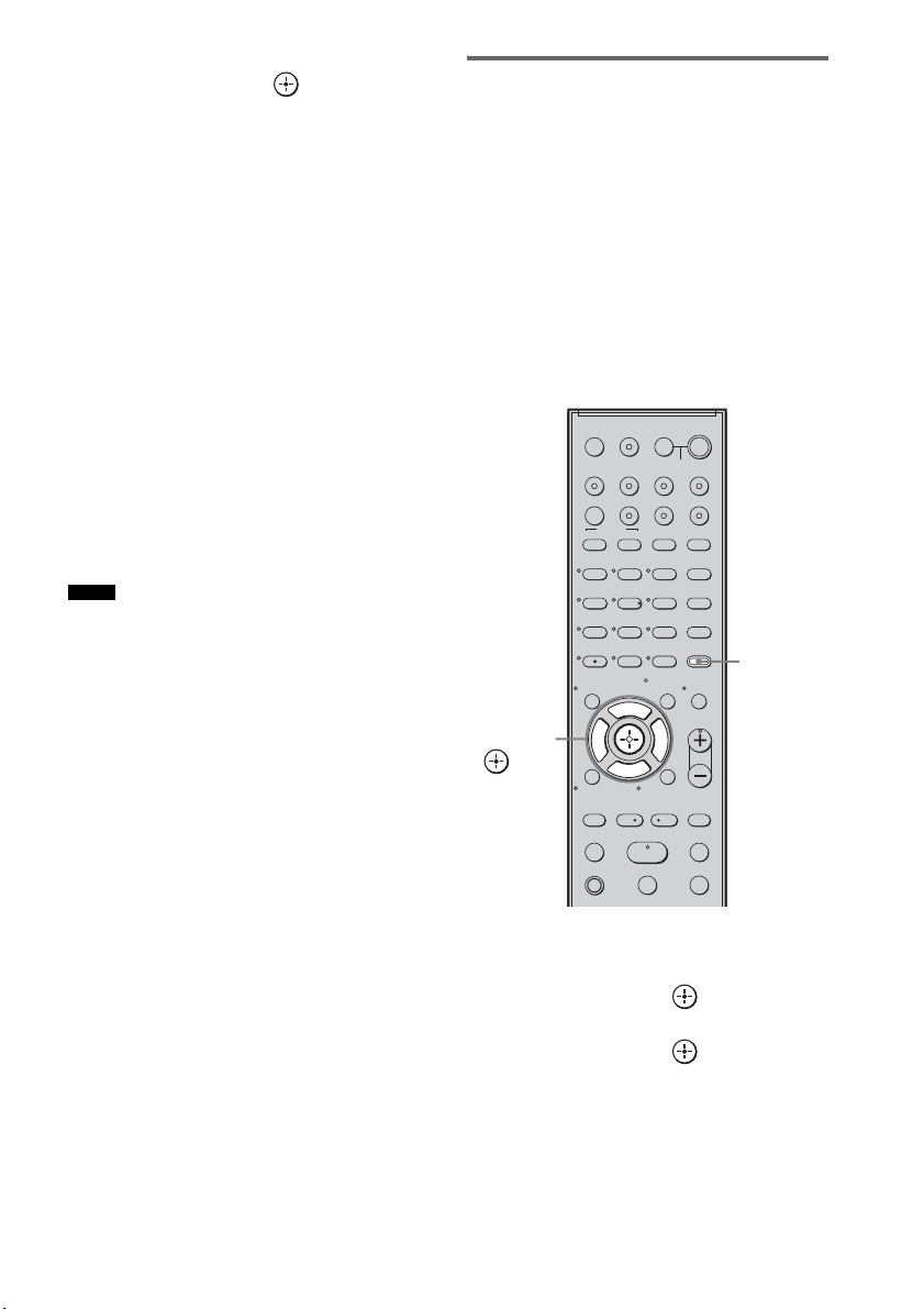
64
US
3 Press x/X repeatedly until “A. ASSIGN”
appears, then press or c.
4 Press x/X to select the audio input you
want to reassign.
• ANALOG VD: reassigns the analog
audio input to the
“VIDEO” function.
• ANALOG TV: reassigns the analog
audio input to the “TV”
function.
• ANALOG SAT: reassigns the analog
audio input to the “SAT”
function.
• ANALOG DVD:reassigns the analog
audio input to the
“DVD” function.
• ANALOG BD: reassigns the analog
audio input to the “BD”
function.
5 Press AMP MENU.
The AMP menu turns off.
• When images of an audio component are output, the
sound may not be output. In this case, check the
following:
– Confirm the audio analog input jacks correspond
with the function.
– Reassign the function.
• You cannot use the analog audio input for the original
input if it has been reassigned to another input.
• You cannot reassign the analog audio input to the
“TUNER/BAND” and “DMPORT” function.
Reassigning the digital audio
input
You can reassign an audio input that has coaxial
(digital) signal to the “DVD” or “SAT” function,
if either one function is not being used.
For example, to output the audio source for DVD
player using the ASSIGNABLE COAXIAL
SAT IN jack on the subwoofer:
• Connect the coaxial output jack of the DVD
player to the ASSIGNABLE COAXIAL SAT
IN jack on the subwoofer.
• Assign the “DVD” function to “COAX DVD”
in the “D. ASSIGN” setting.
1 Press AMP MENU.
2 Press x/X repeatedly until “AUDIO”
appears, then press or c.
3 Press x/X repeatedly until “D. ASSIGN”
appears, then press or c.
Notes
123
46
78
0
ENTER
9
TV INPUTTHEATER
TV
?/1
AV
?/1
TV BD DVD SAT
TOP MENU MENU
BD/DVD
RETURN/EXIT
TV
REPLAY ADVANCE
F1 F2
AMP MENU
CLEAR
DISPLAY
MUTING
TONE
TUNING - TUNING +
NIGHT
MODE
GUIDE
FAVORITEWIDEPICTUREJUMP
DMPORTTUNER/BANDVIDEO
SOUND FIELD
?/1
TV CH -
PRESET -
TV CH +
PRESET +
F
Gg
f
.
HmM
Xx
<
<
>
5
SYSTEM STANDBY
MENU/HOME
TOOLS/
OPTIONS
TV VOL
MASTER VOL
AMP
MENU
C, X, x, c,
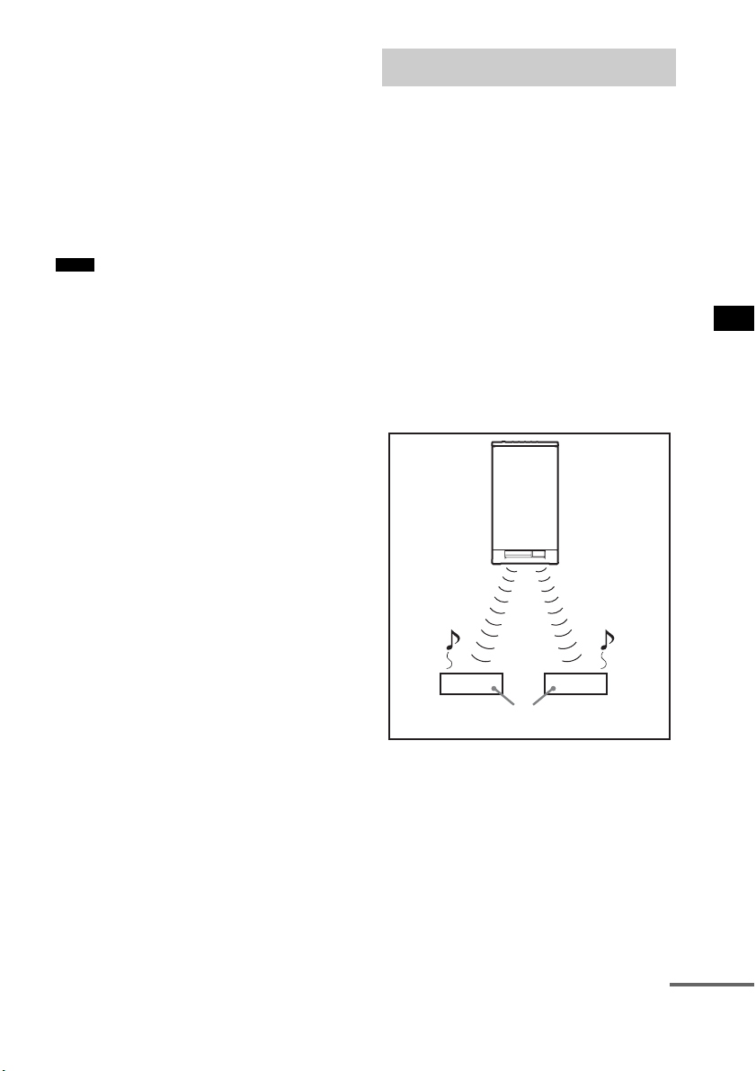
65
US
Advanced Settings
4 Press x/X to select the audio input you
want to reassign.
• COAX SAT: reassigns the coaxial audio
input to the “SAT”
function.
• COAX DVD: reassigns the coaxial audio
input to the “DVD”
function.
5 Press AMP MENU.
The AMP menu turns off.
• You cannot reassign several digital audio inputs to the
same input.
• You cannot use the digital audio input for the original
input if it has been reassigned to another input.
• You cannot reassign the digital audio input to the
“TV,” “BD,” “VIDEO,” “TUNER/BAND,” or
“DMPORT” function.
About S-AIR products
The system is compatible with the S-AIR
function, which allows sound transmission
between the subwoofer and S-AIR product (not
supplied).
When you purchase the S-AIR product, you need
to perform the following settings to establish the
sound transmission.
There are two types of S-AIR product.
• S-AIR main unit (this subwoofer): This is for
transmitting sound. You can use up to three
S-AIR main units. (The number of usable
S-AIR main units depends on the use
environment.)
• S-AIR sub unit: This is for receiving sound.
Notes
Using an S-AIR Product
S-AIR
main unit
S-AIR sub unit
continued
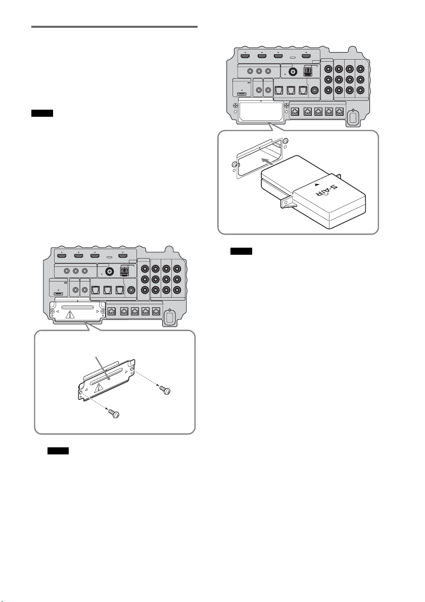
66
US
Inserting the wireless
transmitter/transceiver
To make use of the S-AIR function, you need to
insert the wireless transmitter (not supplied) into
the subwoofer and the wireless transceiver (not
supplied) into the S-AIR product.
• When you insert the wireless transmitter/transceiver,
make sure that the AC power cord (mains lead) is not
connected to a wall outlet (mains).
• Do not touch the terminals of the wireless transmitter/
transceiver.
To insert the wireless transmitter
into the subwoofer
1 Remove the screws and detach the slot
cover.
• Remove the screws from the slot cover bearing
the caution mark. Do not remove other screws.
• The slot cover is no longer necessary; however,
keep it after detaching.
2 Insert the wireless transmitter.
• Insert the wireless transmitter with the S-AIR
logo facing up.
• Insert the wireless transmitter so that the
V
marks are aligned.
• Do not insert other than the wireless transmitter
into the EZW-T100 slot.
Notes
Notes
IR REMOTE
VIDEO
DMPORT
DIGITAL COMPONENT VIDEO
SPEAKER ONLY FOR SS-IS15
ECM-AC2 IR-R100
ANTENNA
HDMI
IR IN IR OUT1 IR OUT2
FM AM
75
COAXIAL
DC 5V
0.7A MAX
FRONT R FRONT L SUR R SUR LCENTER
BD IN DVD IN SAT IN
TV IN DVD IN SAT IN SAT IN
ASSIGNABLE
COAXIAL
AUDI O IN
ASSIGNABLE
VIDEO IN
DVD IN SAT IN
MONITOR
OUT
L
Y
P
B
/
C
B
P
R
/
C
R
R
OPTICAL
TV OUT
EZW-T100
E
Z
W
-
T
1
0
0
Slot cover
Bottom of the subwoofer
Notes
IR REMOTE
VIDEO
DMPORT
DIGITAL COMPONENT VIDEO
SPEAKER ONLY FOR SS-IS15
ECM-AC2 IR-R100
ANTENNA
HDMI
IR IN IR OUT1 IR OUT2
FM AM
75
COAXIAL
DC 5V
0.7A MAX
FRONT R FRONT L SUR R SUR LCENTER
BD IN DVD IN SAT IN
TV IN DVD IN SAT IN SAT IN
ASSIGNABLE
COAXIAL
AUDI O IN
ASSIGNABLE
VIDEO IN
DVD IN SAT IN
MONITOR
OUT
L
Y
P
B
/
C
B
P
R
/
C
R
R
OPTICAL
TV OUT
EZW-T100
E
Z
W
-
T
1
0
0
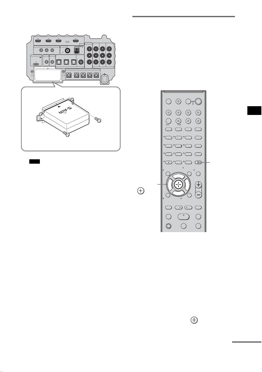
67
US
Advanced Settings
3 Make sure to use the same screws to
secure the wireless transmitter.
• Do not use other screws to fasten the wireless
transmitter.
To insert the wireless transceiver
into the S-AIR product
For details on installing the wireless transceiver
into the S-AIR product, refer to the operating
instructions of the S-AIR product.
Establishing sound
transmission between the
subwoofer and the S-AIR
product
To establish sound transmission, set the S-AIR
products that you use.
After inserting the wireless transmitter/
transceiver, connect the AC power cord (mains
lead).
To set the ID of the subwoofer
Simply by matching the ID of the subwoofer and
the S-AIR product, you can establish sound
transmission. You can use multiple S-AIR
products by setting a different ID for each
component.
1 Turn on the subwoofer.
The subwoofer turns on.
2 Press AMP MENU.
3 Press x/X repeatedly until “S-AIR SET”
appears, then press or c.
Note
IR REMOTE
VIDEO
DMPORT
DIGITAL COMPONENT VIDEO
SPEAKER ONLY FOR SS-IS15
ECM-AC2 IR-R100
ANTENNA
HDMI
IR IN IR OUT1 IR OUT2
FM AM
75
COAXIAL
DC 5V
0.7A MAX
FRONT R FRONT L SUR R SUR LCENTER
BD IN DVD IN SAT IN
TV IN DVD IN SAT IN SAT IN
ASSIGNABLE
COAXIAL
AUDI O IN
ASSIGNABLE
VIDEO IN
DVD IN SAT IN
MONITOR
OUT
L
Y
P
B
/
C
B
P
R
/
C
R
R
OPTICAL
TV OUT
EZW-T100
E
Z
W
-
T
1
0
0
123
46
78
0
ENTER
9
TV INPUTTHEATER
TV
?/1
AV
?/1
TV BD DVD SAT
TOP MENU MENU
BD/DVD
RETURN/EXIT
TV
REPLAY ADVANCE
F1 F2
AMP MENU
CLEAR
DISPLAY
MUTING
TONE
TUNING - TUNING +
NIGHT
MODE
GUIDE
FAVORITEWIDEPICTUREJUMP
DMPORTTUNER/BANDVIDEO
SOUND FIELD
?/1
TV CH -
PRESET -
TV CH +
PRESET +
F
Gg
f
.
HmM
Xx
<
<
>
5
SYSTEM STANDBY
MENU/HOME
TOOLS/
OPTIONS
TV VOL
MASTER VOL
AMP
MENU
C, X, x, c,
continued
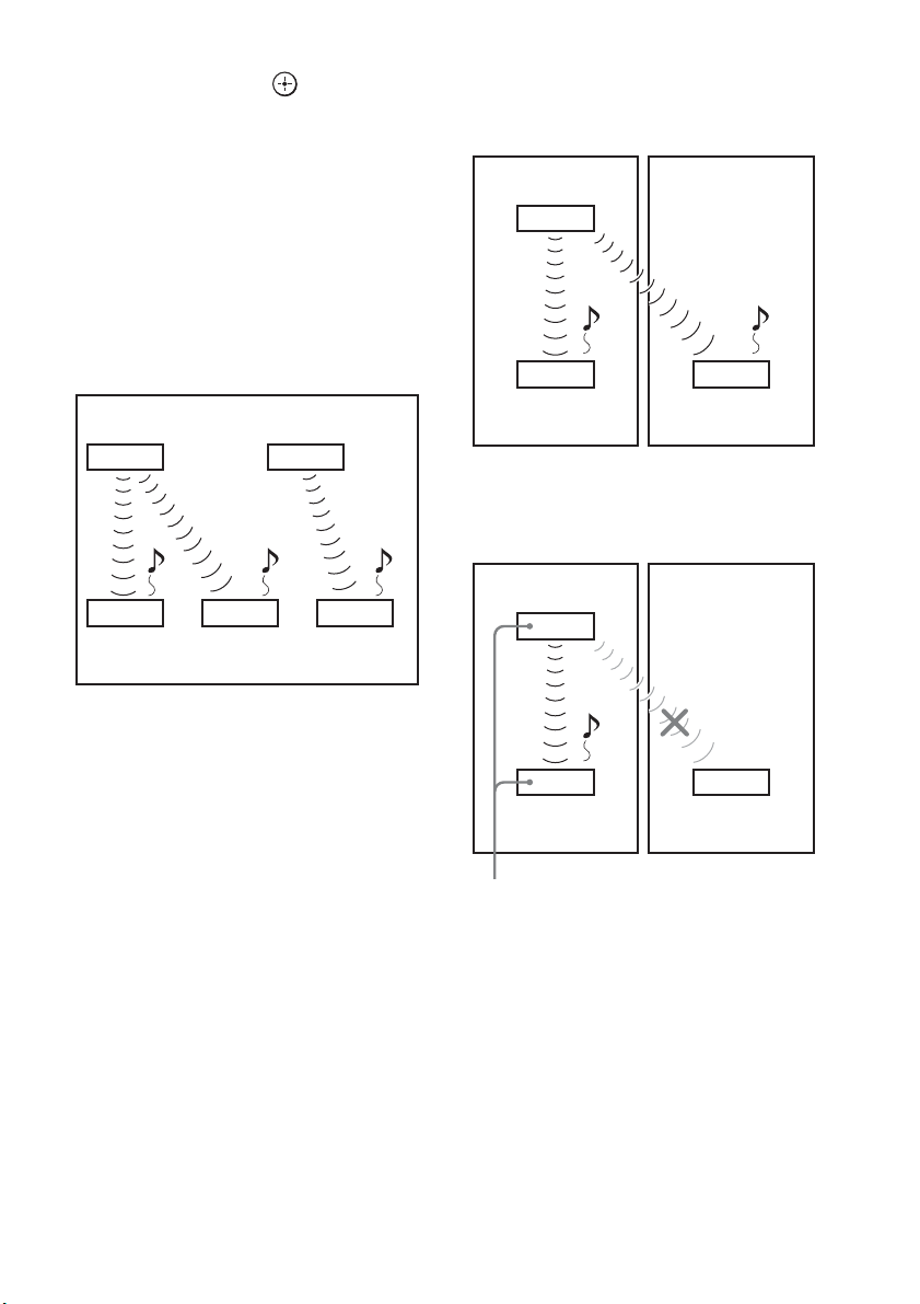
68
US
4 Press x/X repeatedly until “S-AIR ID”
appears, then press or c.
5 Press x/X repeatedly to select the
desired ID (A, B, or C).
6 Press AMP MENU.
The AMP menu turns off.
To set the ID of the S-AIR product
For details on setting the ID of the S-AIR
product, refer to the operating instructions of the
S-AIR product.
The image of established sound
transmission
To perform the pairing operation
It is easy to set the same ID for the subwoofer
and the S-AIR product to establish sound
transmission. However, neighbors may also
receive your system’s sound if IDs are the same,
or you may receive sound from neighbors. To
prevent this, you can identify the subwoofer with
a specific S-AIR product by performing the
pairing operation.
x When you perform pairing
Before pairing, sound transmission is established
by the ID (example).
Sound transmission is established between the
paired subwoofer and the S-AIR product(s).
1 Place the S-AIR product that you want
to pair near the subwoofer.
2 Match the IDs of the subwoofer and the
S-AIR product. To set the ID of the
system, see “To set the ID of the
subwoofer” (page 67).
To set the ID of the S-AIR product, refer to
the operating instructions of the S-AIR
product.
3 Press AMP MENU.
S-AIR main unit A
(this subwoofer)
S-AIR
product A
S-AIR main unit B
S-AIR
product B
S-AIR
product C
ID A ID A ID B
ID A ID B
Your room Neighbor
ID A ID A
ID A
S-AIR
product A
S-AIR
product B
S-AIR main unit A
(this subwoofer)
Your room Neighbor
ID A ID A
ID A
S-AIR
product A
S-AIR
product B
Pairing
S-AIR main unit A
(this subwoofer)

69
US
Advanced Settings
4 Press x/X repeatedly until “S-AIR SET”
appears, then press or c.
5 Press x/X repeatedly until “PAIRING”
appears, then press or c.
6 Press x/X repeatedly to select the
desired setting, then press or c.
• START: the subwoofer starts
pairing.
• CONDITION: you can check the current
ID. When the pairing
setting is not made, “NO
PAIRING” appears in the
top panel display.
7 Start pairing of the S-AIR product.
To start paring of the S-AIR product, refer
to the operating instructions of the S-AIR
product.
When sound transmission is established,
“COMPLETE” appears in the top panel
display.
8 Press AMP MENU.
The AMP menu turns off.
• Perform the pairing of the S-AIR product within
several minutes after step 6. If you do not, pairing is
canceled automatically and the “INCOMPLETE”
appears in the top panel display.
To cancel pairing
Perform the ID setting of the subwoofer
according to the procedure of “To set the ID of
the subwoofer” (page 67). If you select a new ID
(you can select the same ID as before), pairing is
canceled.
Enjoying the system’s sound
by using the S-AIR product
You can enjoy the system’s sound by using the
S-AIR product that is compatible with the S-AIR
mode. The S-AIR product can be installed
anywhere, regardless of the location of the
subwoofer, for enjoying the system’s sound in
another room.
For details of the S-AIR product, refer to the
operating instructions of the S-AIR product.
• Sources with copyright protection may not be
playable on S-AIR products.
1 Set the ID of the S-AIR product to that of
the subwoofer.
To set the ID of the subwoofer, see “To set
the ID of the subwoofer” (page 67).
• When you are using another S-AIR product, do not
change the ID of the subwoofer. Set the ID of the
S-AIR product to the same ID as the subwoofer.
• When you pair the subwoofer and another S-AIR
product by the pairing operation, you need to perform
pairing between the subwoofer and the S-AIR
product. For details, see “To perform the pairing
operation” (page 68).
Note
Note
Notes
continued
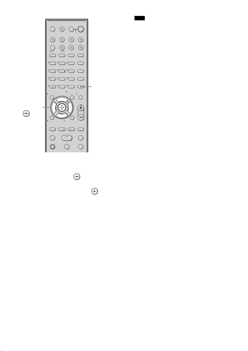
70
US
2 Press AMP MENU.
3 Press x/X repeatedly until “S-AIR SET”
appears, then press or c.
4 Press x/X repeatedly until “S-AIR
MODE” appears, then press or c.
5 Press x/X repeatedly to select the
desired function.
• PARTY: the S-AIR product outputs
sound according to function
set on the subwoofer.
• SEPARATE: you can set the desired
function for the S-AIR
product while functions of
the subwoofer do not
change.
When “SEPARATE” is set,
the functions you can select
are “MAIN UNIT,”
“TUNER FM,” “TUNER
AM” and “DMPORT.”
To enjoy the same function
as the subwoofer, select
“MAIN UNIT.”
• When “TUNER FM” or “TUNER AM” is
selected on the subwoofer, you can only select
the same band for the tuner on the S-AIR
product.
6 Press AMP MENU.
The AMP menu turns off.
7 Select the desired function on the
S-AIR product.
When the sound is other than 2 channel
stereo, multi channel sound is down mixed
to 2 channel.
8 Adjust the volume on the S-AIR
product.
123
46
78
0
ENTER
9
TV INPUTTHEATER
TV
?/1
AV
?/1
TV BD DVD SAT
TOP MENU MENU
BD/DVD
RETURN/EXIT
TV
REPLAY ADVANCE
F1 F2
AMP MENU
CLEAR
DISPLAY
MUTING
TONE
TUNING - TUNING +
NIGHT
MODE
GUIDE
FAVORITEWIDEPICTUREJUMP
DMPORTTUNER/BANDVIDEO
SOUND FIELD
?/1
TV CH -
PRESET -
TV CH +
PRESET +
F
Gg
f
.
HmM
Xx
<
<
>
5
SYSTEM STANDBY
MENU/HOME
TOOLS/
OPTIONS
TV VOL
MASTER VOL
AMP
MENU
C, X, x, c,
Note
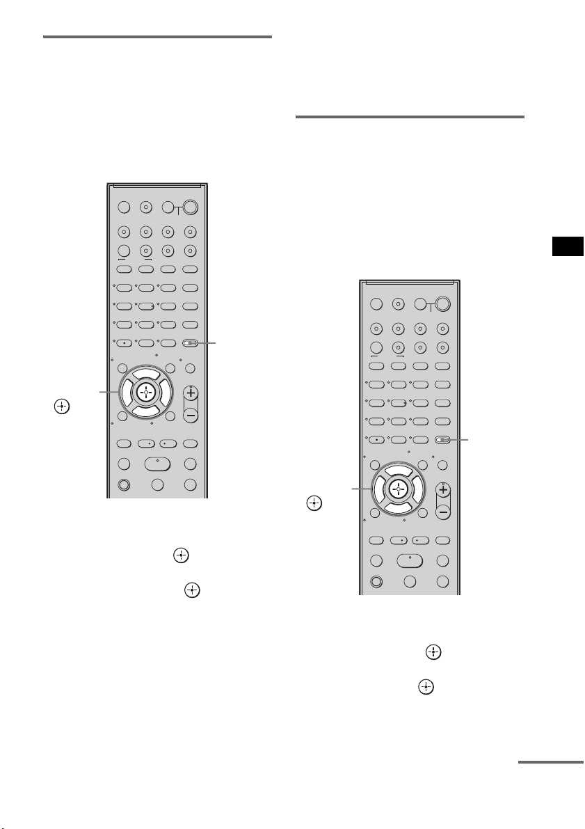
71
US
Advanced Settings
Changing the channel for
improved sound transmission
If sound transmission is unstable, you can
improve it by changing the “RF CHANGE”
setting. The optimal setting differs depending on
the usage environment.
In most cases, you will not need to change this
setting.
1 Press AMP MENU.
2 Press x/X repeatedly until “S-AIR SET”
appears, then press or c.
3 Press x/X repeatedly to select “RF
CHANGE,” then press or c.
4 Press x/X repeatedly to select the
desired setting.
• AUTO: normally select this. The
subwoofer changes “RF
CHANGE” to “ON” or “OFF”
automatically.
• ON: the subwoofer transmits sound by
searching for a better channel to
transmit.
• OFF: the subwoofer transmits sound by
fixing the channel to transmit.
5 Press AMP MENU.
The AMP menu turns off.
To enjoy the S-AIR product
while the subwoofer is in
standby mode
You can enjoy the S-AIR product while the
subwoofer is in standby mode by setting “S-AIR
STBY” to “STBY ON.”
When you use the timer function of the S-AIR
product, set to “STBY ON” in the “S-AIR
STBY” setting.
1 Press AMP MENU.
2 Press x/X repeatedly until “S-AIR SET”
appears, then press or c.
3 Press x/X repeatedly to select “S-AIR
STBY,” then press or c.
4 Press x/X repeatedly to select the
desired setting.
123
46
78
0
ENTER
9
TV INPUTTHEATER
TV
?/1
AV
?/1
TV BD DVD SAT
TOP MENU MENU
BD/DVD
RETURN/EXIT
TV
REPLAY ADVANCE
F1 F2
AMP MENU
CLEAR
DISPLAY
MUTING
TONE
TUNING - TUNING +
NIGHT
MODE
GUIDE
FAVORITEWIDEPICTUREJUMP
DMPORTTUNER/BANDVIDEO
SOUND FIELD
?/1
TV CH -
PRESET -
TV CH +
PRESET +
F
Gg
f
.
HmM
Xx
<
<
>
5
SYSTEM STANDBY
MENU/HOME
TOOLS/
OPTIONS
TV VOL
MASTER VOL
AMP
MENU
C, X, x, c,
continued
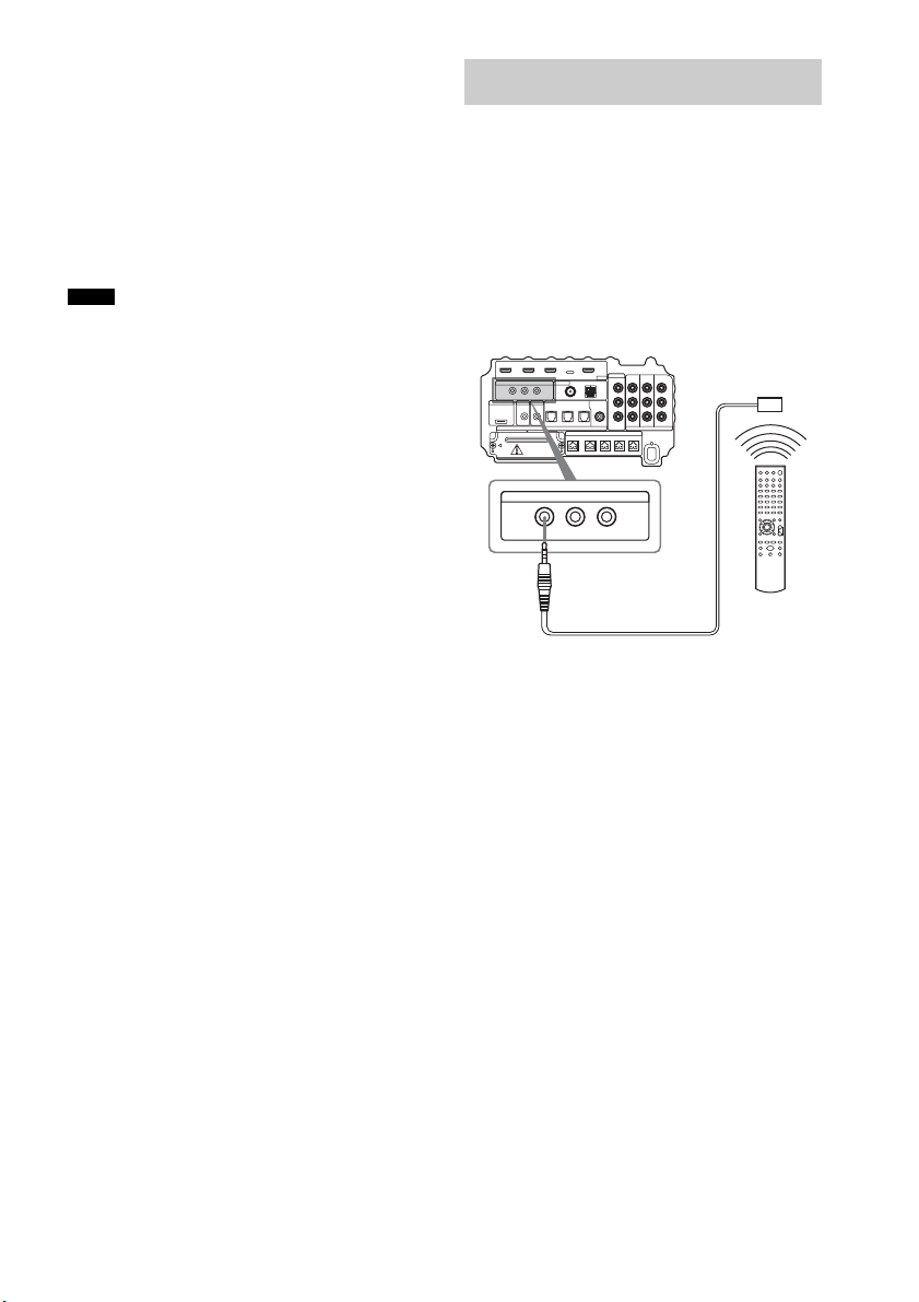
72
US
• STBY OFF: you cannot enjoy the S-AIR
product while the subwoofer
is in standby mode.
• STBY ON: you can enjoy the S-AIR
product while the subwoofer
is in standby mode or turned
on.
5 Press AMP MENU.
The AMP menu turns off.
• When you set “S-AIR STBY” to “STBY ON,” power
consumption during standby mode increases.
• The sound of the S-AIR product may be cut off when
the subwoofer is operated.
About the IR REMOTE jacks
You can operate the subwoofer without pointing
the remote toward the remote commander
receiver if you connect an IR repeater (not
supplied) to the IR REMOTE jack.
Use an IR repeater when you install the remote
commander receiver in a place where signals
from the remote cannot reach.
Notes
Using the IR repeater
IR REMOTE
IR IN IR OUT1 IR OUT2
Bottom of the subwoofer
IR repeater
(not supplied)
Remote

73
US
Additional Information
If you experience any of the following
difficulties while using the system, use this
troubleshooting guide to help remedy the
problem before requesting repairs. Should any
problem persist, consult your nearest Sony
dealer. When bringing the system in for repairs,
be sure to bring in the entire system.
General
The power is not turned on.
• Check that the AC power cord (mains lead)
is connected securely.
If “PROTECTOR” and “PUSH POWER”
appears alternately in the top panel display.
Press ?/1 to turn off the system, and check
the following item after “STANDBY”
disappears.
• Is anything blocking the ventilation holes of
the system?
After checking the above item and fixing
any problems, turn on the system. If the
cause of the problem cannot be found even
after checking the above item, consult your
nearest Sony dealer.
Dolby Digital or DTS multi channel sound is
not reproduced.
• Check that the playing Blu-ray Disc, DVD,
etc., is recorded in Dolby Digital or DTS
format.
• Check that audio setting (settings for the
audio output) of the connected component.
The surround effect cannot be obtained.
• Depending on the digital signal, the
surround processing may not work
(page 38).
No sound or only a very low-level sound is
heard from the speakers.
• Press MASTER VOL + and check the
volume level.
• Press MUTING or MASTER VOL + to
cancel the muting function.
• Press SOUND FIELD and check the
selected sound field.
• Depending on the source, the sound effect of
the speakers may be less noticeable.
The sound comes from the center speaker
only.
• Check the speaker connections and settings
(page 15, 55).
• Depending on the disc, the sound may come
from the center speaker only.
No sound is heard from the center speaker.
• Check the speaker connections and settings
(page 15, 55).
• Set the sound field to other than “OMNI-
DIRECTIONAL SOUND” (page 38).
• Depending on the source, the effect of the
center speaker may be less noticeable.
No sound or only a very low-level sound is
heard from the surround speakers.
• Check the speaker connections and settings
(page 15, 55).
• Check the selected sound field (page 38).
• Depending on the source, the effect of the
surround speakers may be less noticeable.
• A monaural or stereo (not multi channel)
signal is being played.
The sound is delayed compared to the image
of the TV.
• Set “A/V SYNC” to “SYNC OFF” when
“A/V SYNC” is set.
Connected components
There is no sound or only a very low-level
sound no matter which component is selected.
• Check that this system and components are
connected correctly and securely.
• Check that both this system and the selected
component are turned on.
There is no sound from the selected
component.
• Check that the component is connected
correctly to the audio input jacks for that
component.
Additional Information
Troubleshooting
continued

74
US
• Check that the cords are fully inserted into
the jacks on both the component and this
system.
• Check that the component is selected
correctly.
• If you resume playing a disc when volume is
maximum, there may be no sound. In this
case, turn down the volume, turn off the
system and turn on again.
Sound is interrupted or there is noise.
• Check the output audio formats supported
by this system (page 76).
There is no picture or an unclear picture
appears on the TV screen.
• Select the appropriate input using the input
buttons.
• Set your TV to the appropriate input mode.
• Move your audio components away from the
TV.
• Depending on the DIGITAL MEDIA PORT
adapter, video output may not be possible.
The source image input to the HDMI jack on the
subwoofer is not output from the TV.
• Check the HDMI connection.
• Depending on the playback component, you
may need to set up the component. Refer to
the operating instructions of each
component.
There is picture on the TV screen without
sound.
• Check that the audio assignable setting is
correct (page 63, 64).
Control for HDMI
The Control for HDMI function does not work.
• Check the HDMI connection (page 16).
• Make sure “CTRL: HDMI” is set to “CTRL
ON” in AMP menu.
• Make sure the connected component is
compatible with the Control for HDMI
function.
• Check the Control for HDMI settings on the
connected component. For details, refer to
the operating instructions of the component.
• If you change the HDMI connection, or
connect/disconnect the AC power cord
(main lead), or if there is a power failure,
repeat the procedures of “Preparing for the
“BRAVIA” Sync” (page 41).
• The system may not work correctly if you
select a component that is not compatible
with the Control for HDMI function on the
TV side.
No sound is output from the system and the
TV’s speaker.
• Check the volume of the system and the TV.
• Select the input of the system correctly.
The sound is output from both the system and
the TV.
• If the Control for HDMI function is set to
off, or the selected component is not
compatible with the Control for HDMI
function, turn off the sound of the system or
the TV.
The System Power Off function does not work.
• Change the setting of the TV to turn
connected components off automatically
when you turn off the TV. For details, refer
to the operating instructions of the TV.
An image does not appear on the TV.
• Check whether HDMI IN and HDMI OUT
are connected correctly.
S-AIR function
Sound transmission is not established.
• If you use another S-AIR main unit, place it
more than 8 m (26
1
/4 feet) away from the
system.
• Confirm the ID of the subwoofer and the
S-AIR product (page 67).
• You performed pairing the subwoofer and
another S-AIR product. Perform pairing of
the desired S-AIR product (page 68).
• The S-AIR product is paired to another
S-AIR product. Cancel pairing.
• Install the system away from other wireless
products.
• Stop using another wireless product.

75
US
Additional Information
• The S-AIR product is turned off. Make sure
the AC power cord (mains lead) is connected
and turn on the S-AIR product.
No sound is heard from the S-AIR product.
• If you use another S-AIR main unit, place it
more than 8 m (26
1
/4 feet) away from the
system.
• Confirm the ID of the subwoofer and the
S-AIR product (page 67).
• Confirm the pairing setting (page 68).
• Install the S-AIR main unit and S-AIR sub
unit closer together.
• Avoid use of equipment that generates
electromagnetic energy, such as a
microwave oven.
• Install the S-AIR main unit and S-AIR sub
unit away from other wireless products.
• Stop using another wireless product.
• Change the “RF CHANGE” setting
(page 71).
• Change the ID settings of the S-AIR main
unit and S-AIR sub unit.
• Turn off the system and S-AIR product, then
turn them on.
There is noise or the sound skips.
• If you use another S-AIR main unit, place it
more than 8 m (26
1
/4 feet) away from the
system.
• Install the S-AIR main unit and S-AIR sub
unit closer together.
• Avoid use of equipment that generates
electromagnetic energy, such as a
microwave oven.
• Install the S-AIR main unit and S-AIR sub
unit away from other wireless products.
• Stop using another wireless product.
• Change the “RF CHANGE” setting
(page 71).
• Change the ID settings of the S-AIR main
unit and S-AIR sub unit.
Other
The remote does not function.
• Check that the subwoofer and the remote
commander receiver are connected correctly
and securely.
• Point the remote at the remote sensor ( ) on
the remote commander receiver.
• Remove any obstacles in the path between
the remote and the remote commander
receiver.
• Replace both batteries in the remote with
new ones, if they are weak.
• Press one of the input buttons (TV, BD,
DVD, SAT, TUNER/BAND, or DMPORT)
on the remote to select the component you
want to operate (page 50).
The volume turns down when the output
method changes from the TV speaker to the
system speaker.
• The Volume Limit function is working. For
details, see “Using the Volume Limit
function” (page 44).
If the system still does not
operate properly after performing
the above measures, reset the
system as follows:
Use buttons on the subwoofer for the operation.
1 Press ?/1 to turn on the power.
2 Press INPUT SELECTOR, VOLUME –,
?/1 at the same time.
“COLD RESET” appears and the system is
reset. AMP menu, sound field, etc., return to
the default settings.

76
US
Formats supported by this
system
Digital input formats supported by this system
are as follows.
* Linear PCM accepts sampling frequencies of no
more than 96 kHz.
Amplifier section
AUDIO POWER SPECIFICATIONS
For the U.S.A model
POWER OUTPUT AND TOTAL HARMONIC
DISTORTION:
Front L / Front R:
With 10 ohms loads, both channels driven, from 800 -
20,000 Hz; rated 35 watts per channel minimum RMS
power, with no more than 0.7 % total harmonic
distortion from 250 milli watts to rated output
Subwoofer:
With 4 ohms loads, from 30 - 800 Hz; rated 75 watts per
channel minimum RMS power, with no more than
0.7 % total harmonic distortion from 250 milli watts to
rated output
Power output (rated)
For Canadian and Argentine models
Front L / Front R (rated): 35 W + 35 W
(at 10 ohms, 1 kHz, 1 %
THD)
RMS output power (reference)
Front L / Front R*: 50 W + 50 W
(at 10 ohms, 1 kHz, 10 %
THD)
Center*: 50 W
(at 10 ohms, 1 kHz, 10 %
THD)
Surround L / Surround R*: 50 W + 50 W
(at 10 ohms, 1 kHz, 10 %
THD)
Subwoofer*: 100 W (at 4 ohms, 70 Hz,
10 % THD) + 100 W (at 4
ohms, 500 Hz, 10 % THD)
* Depending on the sound field settings and the source,
there may be no sound output.
Inputs (Analog)
VIDEO Sensitivity: 700 mV
Impedance: 33 kohms
Inputs (Digital)
TV, DVD Optical
SAT Coaxial, optical
HDMI section
Connector HDMI 19pin-standard
connector
Video inputs/outputs BD, DVD, SAT:
640 × 480p@60 Hz
720 × [email protected]/60 Hz
1440 × [email protected]/60 Hz
(pixel sent 2 times)
1280 × [email protected]/60 Hz
1920 × 1080i@59.94/
60 Hz
1920 × [email protected]4/
60 Hz
720 × 576p@50 Hz
1440 × 576p@50 Hz
(pixel sent 2 times)
1280 × 720p@50 Hz
1920 × 1080i@50 Hz
1920 × 1080p@50 Hz
1920 × 1080p@24 Hz
Audio inputs BD, DVD, SAT: Linear
PCM 7.1ch/
Dolby Digital/ DTS
Tuner section
System PLL quartz-locked digital
synthesizer
FM tuner section
Tuning range
North American models: 87.5 – 108.0 MHz
(100 kHz step)
Argentine models: 87.5 – 108.0 MHz
(50 kHz step)
Antenna (aerial) FM wire antenna (aerial)
Antenna (aerial) terminals 75 ohms, unbalanced
Intermediate frequency 10.7 MHz
Specifications
Format Supported/Not supported
Dolby Digital a
DTS a
Linear PCM (2ch)* a
Linear PCM (5.1ch,
7.1ch)* (Only on
HDMI)
a
Dolby Digital Plus ×
Dolby True HD ×
DTS-HD ×

77
US
Additional Information
AM tuner section
Tuning range 530 – 1,710 kHz (with the
interval set at 10 kHz)
531 – 1,710 kHz (with the
interval set at 9 kHz)
Antenna (aerial) AM loop antenna (aerial)
Intermediate frequency 450 kHz
Video section
Input VIDEO: 1 Vp-p 75 ohms
Inputs/Outputs COMPONENT:
Y: 1 Vp-p 75 ohms
PB/CB, PR/CR: 0.7 Vp-p
75 ohms
Speakers
Front/Center/Surround (SS-IS15)
Speaker system Full range speaker system
Speaker unit 35 mm (1
7
/16 inches)
Rated impedance 10 ohms
Dimensions (approx.) 45 × 55 × 40 mm
(1
13
/16 × 2
1
/4 × 1
5
/8 inches)
(w/h/d)
Mass (approx.) 0.07 kg (3 oz)
Speaker cords 4.5 m × 2, 3 m × 1, 12 m ×
2 (14.7 ft. × 2, 9.8 ft. × 1,
39.3 ft. × 2)
Subwoofer (SA-WIS100)
Speaker system 2 Way 2 Drivers
Subwoofer speaker system
Speaker unit 120 mm + 160 mm (4
3
/4
inches + 6
3
/8 inches)
Rated impedance 4 ohms
Dimensions (approx.) 238 × 441 × 434 mm
(9
3
/8 × 17
3
/8 × 17
1
/8
inches) (w/h/d)
Mass (approx.) 14.5 kg (31 lb 16 oz)
Power requirements
North American models: 120 V AC, 60Hz
Argentine models: 220 – 240 V AC, 50/60 Hz
Power consumption
On: 115 W
Standby mode: 0.3W (when “CTRL: HDMI”
and “S-AIR STBY” are set to “OFF.”)
Power output
(DIGITAL MEDIA PORT)DC OUT: 5 V, 700 mA
Remote commander receiver (IR-R100)
Dimensions (approx.) 46 × 19 × 45 mm
(1
13
/16 ×
3
/4 × 1
13
/16 inches)
(w/h/d)
Mass (approx.) 0.15 kg (6 oz)
Design and specifications are subject to change without
notice.
• Standby power consumption 0.3 W.
• Halogenated flame retardants are not
used in the certain printed wiring
boards.
• Over 85 % power efficiency of
amplifier block is achieved with the
full digital amplifier, S-master.

78
US
Dolby Digital
This movie theater sound format is more
advanced than Dolby Surround Pro Logic. In this
format, the surround speakers output stereo
sound with an expanded frequency range, and a
subwoofer channel for deep bass is
independently provided. This format is also
called “5.1” with the subwoofer channel
designed as the 0.1 channel (since it functions
only when a deep bass effect is needed). All six
channels in this format are recorded separately
for superior channel separation. Furthermore,
since all the signals are processed digitally, less
signal degradation occurs.
Dolby Pro Logic II
Dolby Pro Logic II creates five full-bandwidth
output channels from 2 channel sources. This is
done using an advanced, high-purity matrix
surround decoder that extracts the spatial
properties of the original recording without
adding any new sounds or tonal colorations.
DTS
Digital audio compression technology
developed by Digital Theater Systems, Inc. This
technology conforms to 5.1-channel surround.
This format comprises of stereo rear channel and
there is discrete subwoofer channel in this
format. DTS provides the same 5.1 discrete
channels of high quality digital audio. The good
channel separation is realized due to the all
channel data being recorded discretely and
processed in digitally.
HDMI
HDMI (High-Definition Multimedia Interface)
is an interface that supports both video and audio
on a single digital connection, allowing you to
enjoy high quality digital picture and sound. The
HDMI specification supports HDCP (High-
bandwidth Digital Contents Protection), a copy
protection technology that incorporates coding
technology for digital video signals.
PCM (Pulse Code Modulation)
A method of converting analog audio to digital
audio for easy enjoyment of digital sound.
S-AIR (Sony Audio Interactive Radio
frequency)
Recent times have seen the rapid spread of DVD
media, Digital Broadcasting, and other high-
quality media.
To ensure that the subtle nuances of these high-
quality media are transmitted with no
deterioration, Sony has developed a technology
called “S-AIR” for the radio transmission of
digital audio signals with no compression, and
has incorporated this technology into the
EZWRT10/EZW-T100.
This technology transfers digital audio signals
with no compression using the 2.4 GHz band
range of ISM band (Industrial, Scientific, and
Medical band), such as wireless LANs and
Bluetooth applications.
S-master
S-master is an all-digital amplifier technology
developed by Sony, which effectively minimizes
the occurrence of sound fragmentation and jitter,
delivering superb dialog clarity and faithful
reproduction of the original sound. The compact
amplifier section supports a higher power
efficiency and improved thermal performance.
x.v.Color
x.v.Color is a more familiar term for the xvYCC
standard proposed by Sony, and is a trademark of
Sony. xvYCC is an international standard for
color space in video.
This standard can express a wider color range
than the currently used broadcast standard.
Glossary

79
US
Additional Information
A
A. ASSIGN 63
A. CAL CLEAR
28
A. CAL MENU
26, 28
A. CAL START
26
A/V SYNC
59
AM Step
46
AMP menu
54
AUDIO
63, 64
AUDIO DRC
60
Auto Calibration
24
B
Blu-ray Disc player (recorder)
connecting
16
“BRAVIA” Sync
41
C
CENTER SP 55
CNT DIST
56
CNT LEVEL
57
CTRL: HDMI
42
CUSTOMIZE
58, 59, 60, 61, 62
D
D. ASSIGN 64
DIGITAL MEDIA PORT
connecting 30
DIMMER
61
DISPLAY
49, 61
DUAL MONO
58
DVD player (recorder)
connecting 16, 19
F
FL DIST 56
FL LEVEL
57
FM Mode
48
FR DIST
56
FR LEVEL
57
H
HDMI
connecting
16
I
Installing 7
L
LEVEL 57
M
MUTING 34
N
Naming preset stations 48
NIGHT MODE
40
P
PAIRING 68
“PlayStation 3”
connecting 16
Presetting radio stations
46
R
Radio 47
Radio Stations
46
Reassigning the analog audio input
63
Reassigning the digital audio input
64
Remote
assignments 52
before use
6
operating
34, 50
RF CHANGE
71
Index
continued

80
US
S
S-AIR 65
S-AIR ID
67
S-AIR MODE
69
S-AIR SET
67, 69, 71
S-AIR STBY
71
Satellite tuner
connecting 16, 20
SET HDMI
42, 44
SL DIST
56
SL LEVEL
57
Sleep timer
62
Sound field
38
SP SETUP
55, 56
Speakers level
57
Speakers setting
55, 56
SR DIST
56
SR LEVEL
57
SUR SP
55
SW DIST
56
SW LEVEL
57
T
TEST TONE 57
TONE
40
V
VCR
connecting
21
VOL LIMIT
44

2
ES
3
Para reducir el riesgo de incendio o
descarga eléctrica, no exponga este
aparato a la lluvia ni a la humedad.
Las pilas o los aparatos instalados con pilas no deben
exponerse al calor excesivo como a la luz solar, el
fuego o similar.
No instale el aparato en un espacio cerrado, como una
estantería o un armario empotrado.
Solo para uso en interiores.
Para los clientes en Estados Unidos
La traducción del texto de las etiquetas es la siguiente:
PRECAUCIÓN
RIESGO DE DESCARGA ELÉCTRICA
NO ABRIR
PRECAUCIÓN: PARA REDUCIR EL RIESGO DE
DESCARGA ELÉCTRICA, NO RETIRE LA
CUBIERTA (O TAPA POSTERIOR).
EL INTERIOR DE LA UNIDAD NO CONTIENE
NINGÚN COMPONENTE QUE PUEDA REPARAR
EL USUARIO.
ACUDA A PERSONAL CUALIFICADO PARA
CUALQUIER TAREA DE REPARACIÓN.
Este símbolo tiene por objeto advertir al
usuario de la presencia de “voltaje peligroso”
desprovisto de aislamiento en el interior del
producto que puede ser de suficiente magnitud como
para presentar un riesgo de descarga eléctrica para las
personas.
Este símbolo tiene por objeto advertir al
usuario de la presencia de instrucciones
importantes de funcionamiento y
mantenimiento (servicio técnico) en la documentación
que acompaña a este aparato.
Para los clientes en Argentina
Para evitar el riesgo de incendio, no cubra la ventilación
del aparato con periódicos, manteles, cortinas, etc., ni
coloque velas encendidas sobre el aparato.
Para los clientes en Canadá y Argentina
Para evitar el riesgo de incendio o electrocución, no
coloque sobre el aparato objetos que contengan
líquidos como, por ejemplo, un jarrón.
Instrucciones importantes de
seguridad
1) Lea estas instrucciones.
2) Conserve estas instrucciones.
3) Respete todas las advertencias.
4) Siga todas las instrucciones.
5) No utilice este aparato cerca del agua.
6) Limpie el aparato únicamente con un paño seco.
7) No bloquee las aberturas de ventilación. Siga las
instrucciones del fabricante para instalar el aparato.
8) No instale el aparato cerca de fuentes de calor como
radiadores, salidas de calefacción, estufas u otros
aparatos (incluidos amplificadores) que generen
calor.
9) No ponga a prueba la función de seguridad del
enchufe polarizado o de tipo de conexión a tierra.
Un enchufe polarizado tiene dos patas, una más
ancha que la otra. Un enchufe de tipo conexión a
tierra tiene dos patas y una tercera de conexión a
tierra. La pata ancha o la tercera clavija se
suministra para su seguridad. Si el enchufe
suministrado no cabe en la toma de corriente,
póngase en contacto con un electricista para
sustituir la toma de corriente obsoleta.
10) Para proteger el cable de alimentación, sitúelo en un
lugar fuera de paso o donde pueda ser aplastado,
especialmente en los enchufes, los receptáculos y el
punto donde sale del aparato.
11) Utilice únicamente los accesorios que especifica el
fabricante.
12) Utilice el aparato únicamente con el carro, base,
trípode, soporte o mesa que especifique el
fabricante o que se venda con el aparato. Si utiliza
un carro, tenga precaución al mover el conjunto del
carro y el aparato para evitar dañarse en el caso de
una caída.
ADVERTENCIA

3
ES
GB
ESES
13) Desconecte el aparato durante tormentas eléctricas
o si no lo va a utilizar durante períodos prolongados
de tiempo.
14) Ponga cualquier tipo de reparación en manos de
personal de asistencia técnica cualificado. Es
necesario llevar a cabo una reparación cuando se ha
deteriorado el aparato de alguna manera, como
cuando se ha dañado un cable de fuente de
alimentación o enchufe, se ha vertido líquido o se
ha caído algún objeto dentro del aparato, el aparato
se ha expuesto a la lluvia o a la humedad, no
funciona normalmente o se ha caído.
ADVERTENCIA
Este equipo se ha probado y cumple con las
restricciones de los aparatos digitales de Clase B, de
acuerdo con la sección 15 del reglamento de la FCC.
Estas restricciones se han diseñado para proporcionar
protección suficiente contra interferencias nocivas en
instalaciones domésticas. Este equipo genera, utiliza y
puede irradiar energía de radio frecuencia y, si no se
instala y utiliza siguiendo las instrucciones, puede
provocar interferencias en las radiocomunicaciones.
Sin embargo, no se garantiza que no se produzcan
interferencias en una instalación determinada. Si el
equipo produce interferencias en la recepción de radio
y televisión, lo que se puede determinar conectando y
desconectando el equipo, el usuario debería intentar
corregir las interferencias siguiendo uno o varios de los
siguientes procedimientos:
– Reorientar o reubicar la antena receptora.
– Aumentar la separación entre el equipo y el receptor.
– Conectar el equipo a una toma o a un circuito distinto
al que está conectado el receptor.
– Ponerse en contacto con el distribuidor o con un
técnico con experiencia en radio y televisión para
obtener asistencia.
PRECAUCIÓN
Le advertimos de que cualquier cambio o modificación
que no se apruebe de modo explícito en este manual
podría anular su autorización para utilizar este equipo.
Nota para el instalador del sistema CATV:
Esta nota pretende llamar la atención del instalador del
sistema CATV en relación con el artículo 820-40 del
código NEC, que proporciona las pautas para una
adecuada conexión a tierra y, en particular, especifica
que el cable de conexión a tierra debe estar conectado
al sistema de toma de tierra del edificio lo más cerca
posible de la entrada del cable.
Registro del propietario
Los números de modelo y de serie se encuentran en la parte
posterior del altavoz potenciador de graves. Anote los
números de serie en los espacios provistos a continuación.
Indíquelos siempre que acuda a su distribuidor Sony en
relación con este producto.
N.º de modelo HT-IS100
N.º de serie
Este sistema incorpora Dolby* Digital, Pro Logic
Surround y el sistema DTS** Digital Surround.
* Fabricado con licencia de Dolby Laboratories.
“Dolby”, “Pro Logic” y el símbolo de la doble D son
marcas comerciales de Dolby Laboratories.
**Fabricado bajo licencia amparado por las patentes de
los Estados Unidos: 5.451.942, 5.956.674,
5.974.380, 5.978.762, 6.487.535 y otras patentes
estadounidenses e internacionales emitidas y
pendientes. DTS y DTS Digital Surround son
marcas comerciales registradas y los logotipos y el
símbolo de DTS son marcas comerciales de DTS,
Inc. © 1996-2007 DTS, Inc. Todos los derechos
reservados.
Este sistema incorpora tecnología High-Definition
Multimedia Interface (HDMI™).
HDMI, el logotipo de HDMI y High-Definition
Multimedia Interface son marcas comerciales o marcas
comerciales registradas de HDMI Licensing LLC.
“BRAVIA” es una marca comercial de Sony
Corporation.
“S-AIR” y su logotipo son marcas comerciales de Sony
Corporation.

4
ES
Seguridad
• Si se introduce algún objeto o cae líquido en el
sistema, desenchúfelo y haga que lo revise un técnico
especializado antes de volver a utilizarlo.
• No se suba encima del altavoz potenciador de graves,
ya que podría caerse y provocarse lesiones o bien
causar daños en el sistema.
Fuente de alimentación
• Antes de utilizar el sistema, verifique que el voltaje
de funcionamiento coincide con el suministro de
alimentación del país en el que va a utilizarlo. Puede
encontrar el voltaje de funcionamiento en la placa
situada en la parte posterior del altavoz potenciador
de graves.
• Si no va a utilizar el sistema durante un período
prolongado de tiempo, no olvide desconectarlo de la
toma de pared. Para desconectar el cable de
alimentación de ca, tire del enchufe, nunca del cable.
• Una punta del enchufe es más ancha que el resto por
motivos de seguridad: sólo encaja en la toma de pared
de una sola forma. Si no consigue insertar el enchufe
por completo en la toma, póngase en contacto con su
distribuidor.
• El cable de alimentación de ca sólo deberá ser
sustituido en un establecimiento cualificado.
• Aunque apague el sistema, no se desconectará de la
fuente de alimentación de ca mientras permanezca
conectado a la toma de pared.
• Instale este sistema de tal forma que pueda
desenchufar el cable de alimentación de la toma de
pared inmediatamente en caso de emergencia.
Acumulación de calor
Aunque el sistema se caliente durante el
funcionamiento, no se trata de un defecto. Si utiliza el
sistema continuamente a un volumen elevado, la
temperatura de la parte superior, lateral e inferior del
sistema aumenta considerablemente. Para evitar
quemaduras, no toque el sistema.
Ubicación
• Coloque el sistema en un lugar con ventilación
adecuada para evitar la acumulación de calor y
prolongar la vida del sistema.
• No coloque el sistema cerca de fuentes de calor o en
lugares expuestos a la luz solar directa, el polvo o
tensiones mecánicas.
• No coloque cerca del altavoz potenciador de graves
objetos que puedan obstruir los orificios de
ventilación y provocar problemas de funcionamiento.
• No coloque el sistema cerca de equipos como
televisores, videograbadoras o radiocasetes. (Si el
sistema se utiliza junto con un televisor, una
videograbadora o un radiocasete y está situado
demasiado cerca de dichos equipos, pueden
originarse ruidos y la calidad de la imagen puede
disminuir. Esta posibilidad es especialmente probable
si se utiliza una antena interior. Por tanto,
recomendamos utilizar una antena exterior.)
• Tenga cuidado cuando coloque el sistema en
superficies con tratamientos especiales (de cera,
aceite, abrillantador, etc.), ya que podría desteñir o
decolorar la superficie.
Funcionamiento
Antes de conectar otros componentes, verifique que ha
apagado y desenchufado el sistema.
Si detecta un color irregular en una
pantalla de televisor cercana
El sistema dispone de protección magnética para
permitir su instalación junto a un televisor. Sin
embargo, en algunos televisores pueden observarse
todavía irregularidades con el color.
Si se observan irregularidades en el
color...
Apague el televisor y vuelva a encenderlo 15 o 30
minutos después.
Si se observan de nuevo
irregularidades en el color...
Coloque el sistema en un punto más alejado del
televisor.
Limpieza
Limpie el sistema con un paño seco y suave. No utilice
estropajos abrasivos, detergente en polvo ni
disolventes, como alcohol o bencina.
Si desea realizar alguna consulta o solucionar algún
problema relacionado con el sistema, póngase en
contacto con el distribuidor Sony más próximo.
Precauciones

5
ES
Precauciones ............................................4
Procedimientos iniciales
Accesorios suministrados.........................6
Paso 1: colocación de los altavoces .........7
Paso 2: conexión de los altavoces..........15
Paso 3a: conexión de los componentes con
las tomas HDMI...............................16
Paso 3b: conexión de los componentes sin
las tomas HDMI...............................18
Paso 4: conexión de la antena................22
Paso 5: conexión del cable de alimentación
de ca.................................................24
Paso 6: calibración de los ajustes
adecuados de forma automática.......24
(Autocalibración)
Configuración de la salida de sonido del
componente conectado ....................29
Función para la conversión de señales de
vídeo ................................................30
Conexión de otros componentes ............31
Opciones de reproducción
Índice de componentes y controles........33
Ver la televisión.....................................36
Utilización de otros componentes..........37
Funciones de sonido
envolvente
Cómo disfrutar del efecto de sonido
envolvente........................................39
Ajuste del nivel de graves, medios y
agudos..............................................41
Reproducción de películas de noche......42
Funciones de “BRAVIA” Sync
¿Qué es “BRAVIA” Sync? ....................43
Preparativos para utilizar “BRAVIA”
Sync .................................................43
Utilización de Blu-ray Disc/DVD..........45
(Reproducción mediante una
pulsación)
Cómo escuchar el sonido del televisor
desde los altavoces...........................45
(Control de audio del sistema)
Desactivación del televisor, el sistema y
los componentes conectados........... 47
(Apagado del sistema)
Funciones del sintonizador
Memorización de emisoras de radio...... 48
Cómo escuchar la radio......................... 49
Ajustes avanzados
Control de los componentes Sony
conectados con el mando a
distancia .......................................... 52
Modificación de las asignaciones de los
botones de entrada del mando a
distancia .......................................... 55
Configuración y ajustes mediante el menú
del amplificador .............................. 56
Reasignación de las entradas de
audio................................................ 66
Utilización de un producto S-AIR......... 68
Utilización del repetidor de
infrarrojos........................................ 76
Información complementaria
Solución de problemas .......................... 77
Especificaciones.................................... 80
Glosario................................................. 82
Índice alfabético .................................... 84
Tabla de contenido
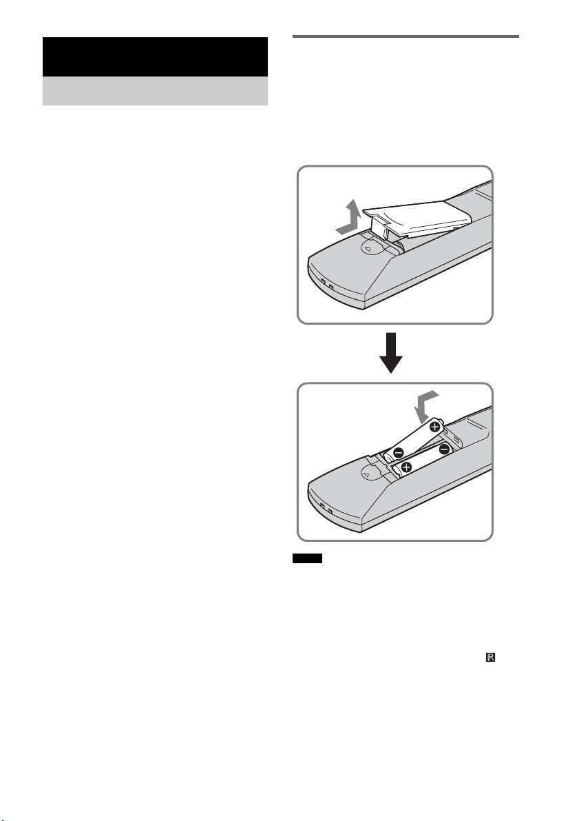
6
ES
Compruebe que se incluyen los siguientes
accesorios en el paquete.
Mando a distancia (RM-AAU036) (1)
Pilas de tamaño AA (R6) (2)
Cable óptico (2,5 m) (98
1
/
2
pulgadas) (1)
Antena monofilar de FM (1)
Antena cerrada de AM (1)
Micrófono de calibración (1)
Altavoz (con receptor de mando a
distancia) (1)
Altavoces (4)
Soporte de altavoz adicional (1)
Soportes (5)
Llave (1)
Tornillo (+PSW4 × 12) (1)
Manual de instrucciones (1)
Guía de inicio rápido (tarjeta) (1)
Inserción de las pilas en el
mando a distancia
Es posible controlar el sistema mediante el
mando a distancia suministrado. Inserte dos pilas
de tamaño AA (R6) de modo que los polos + y –
de éstas coincidan con las marcas del interior del
compartimento.
• No deje el mando a distancia en lugares
extremadamente cálidos o húmedos.
• No utilice pilas nuevas con pilas usadas.
• No permita que se introduzcan sustancias extrañas en
el mando a distancia, especialmente al sustituir las
pilas.
• No exponga el sensor del mando a distancia ( ) a la
luz directa del sol ni a dispositivos de iluminación. De
lo contrario, podría ocasionar un fallo de
funcionamiento.
• Cuando no vaya a utilizar el mando a distancia
durante mucho tiempo, extraiga las pilas para evitar
posibles daños por fugas y corrosión de las mismas.
Procedimientos iniciales
Accesorios suministrados
Notas
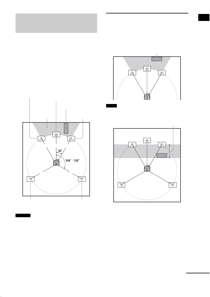
7
ES
Procedimientos iniciales
Para obtener el mejor sonido envolvente posible,
todos los altavoces, excepto el altavoz
potenciador de graves, deben estar situados a la
misma distancia de la posición de escucha (1).
Sony recomienda situar el altavoz potenciador de
graves en el punto (2).
Coloque los altavoces y el altavoz potenciador
de graves tal como se muestra a continuación.
• También puede situar el altavoz potenciador de graves
en uno de los laterales, frente a la posición de escucha.
• Al instalar el altavoz, puede que el frontal del altavoz
no sea del todo estable. En estos casos, utilice
abrazaderas o cinta adhesiva normales para fijar el
cable del altavoz.
Uso correcto del altavoz
potenciador de graves
Para potenciar los graves, coloque el altavoz
potenciador de graves lo más cerca posible de
una pared.
• Si desea colocar el altavoz potenciador de graves
frente al altavoz frontal, la distancia debe ser inferior
a los 0,5 m (1,6 pies).*
Paso 1: colocación de los
altavoces
Consejos
1 1 1
11
2
Altavoz potenciador
de graves
Altavoz central
Altavoz frontal
derecho
Altavoz frontal
izquierdo
Altavoz de sonido
envolvente izquierdo
Altavoz de sonido
envolvente derecho
Notas
Junto a la pared
*
continúa
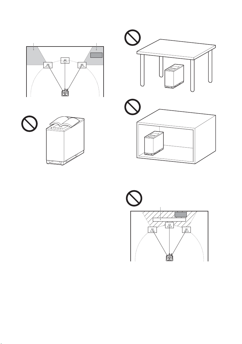
8
ES
• Puede que los graves no tengan la calidad necesaria si
coloca el altavoz potenciador de graves fuera del
intervalo (3). Deberá ajustar la distancia desde la
posición de escucha.
• No coloque objetos sobre el altavoz potenciador de
graves, en la zona del altavoz.
• No coloque el altavoz potenciador de graves debajo
de una mesa o dentro de un armario.
• No coloque el altavoz potenciador de graves detrás de
un obstáculo, como un televisor, ya que el sonido de
rango medio podría perderse.
33
Televisor, etc.
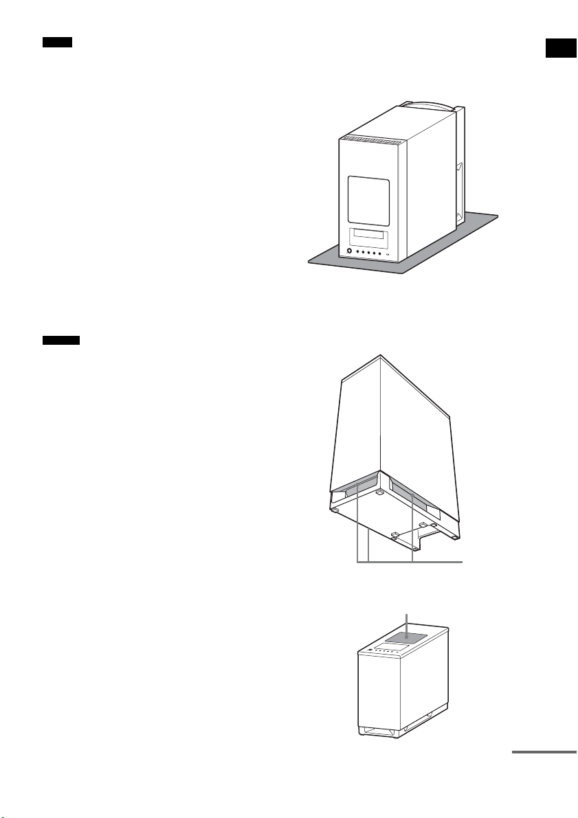
9
ES
Procedimientos iniciales
• No coloque los altavoces inclinados.
• No coloque los altavoces en puntos:
– Extremadamente fríos o calientes
– Sucios o polvorientos
– Muy húmedos
– Sujetos a vibraciones
– Expuestos a la luz solar directa
• Coloque con precaución los altavoces y los soportes
de altavoces (no suministrado) incorporados con los
altavoces en superficies con un tratamiento especial
(cera, aceite, superficies pulidas, etc.), ya que podría
ocasionar manchas o decoloración.
• Al limpiar el sistema, utilice un paño suave, como una
gamuza.
• No utilice estropajos abrasivos, detergente en polvo ni
disolventes, como alcohol o bencina.
• En función de la ubicación del altavoz potenciador de
graves, pueden producirse distorsiones en la pantalla
del televisor. En estos casos, aleje el altavoz
potenciador de graves del televisor.
• Al cambiar las posiciones de los altavoces, Sony
recomienda modificar los ajustes. Para obtener más
información, consulte “Paso 6: calibración de los
ajustes adecuados de forma automática” (página 24).
Notas sobre el uso del altavoz
potenciador de graves
• Coloque un paño suave debajo del altavoz
potenciador de graves cuando lo gire para conectarlo.
• No ponga la mano en la hendidura del altavoz
potenciador de graves al levantarlo. Si lo hace, podría
dañar el motor del altavoz potenciador de graves. Al
levantar el altavoz potenciador de graves, sujételo por
su parte inferior.
• No presione la parte superior del altavoz potenciador
de graves, en la zona del altavoz.
Notas
Consejo
Hendiduras
Altavoz
continúa
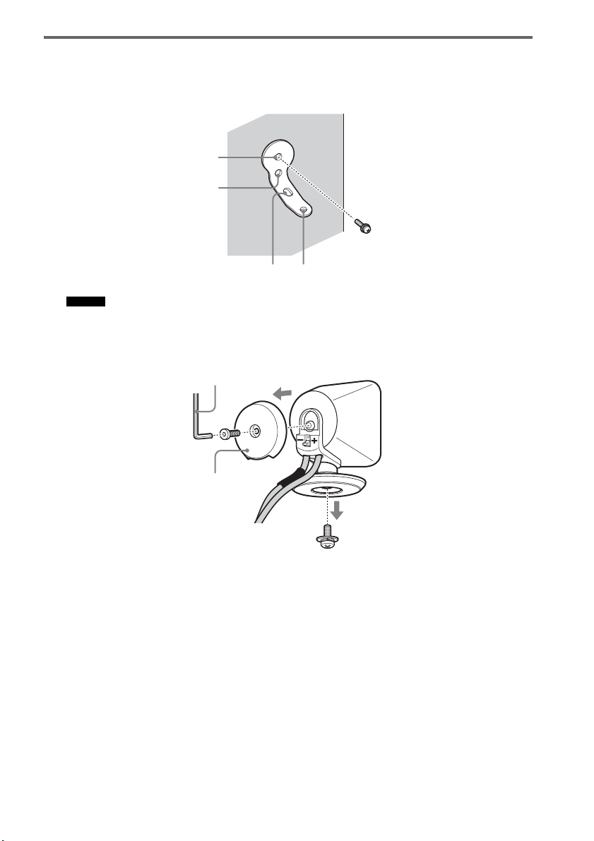
10
ES
Instalación de los altavoces en la pared
1 Prepare tornillos (no suministrado) adecuados para los orificios del soporte.
2 Fije el soporte a la pared con el orificio 1.
• Para impedir que el altavoz se mueva, utilice también el orificio 2.
3 Quite la tapa posterior con la llave (suministrado) y retire el soporte del altavoz con la
ayuda de un destornillador (+) (no suministrado).
Consejo
1
34
2
Tapa posterior
Llave (suministrado)
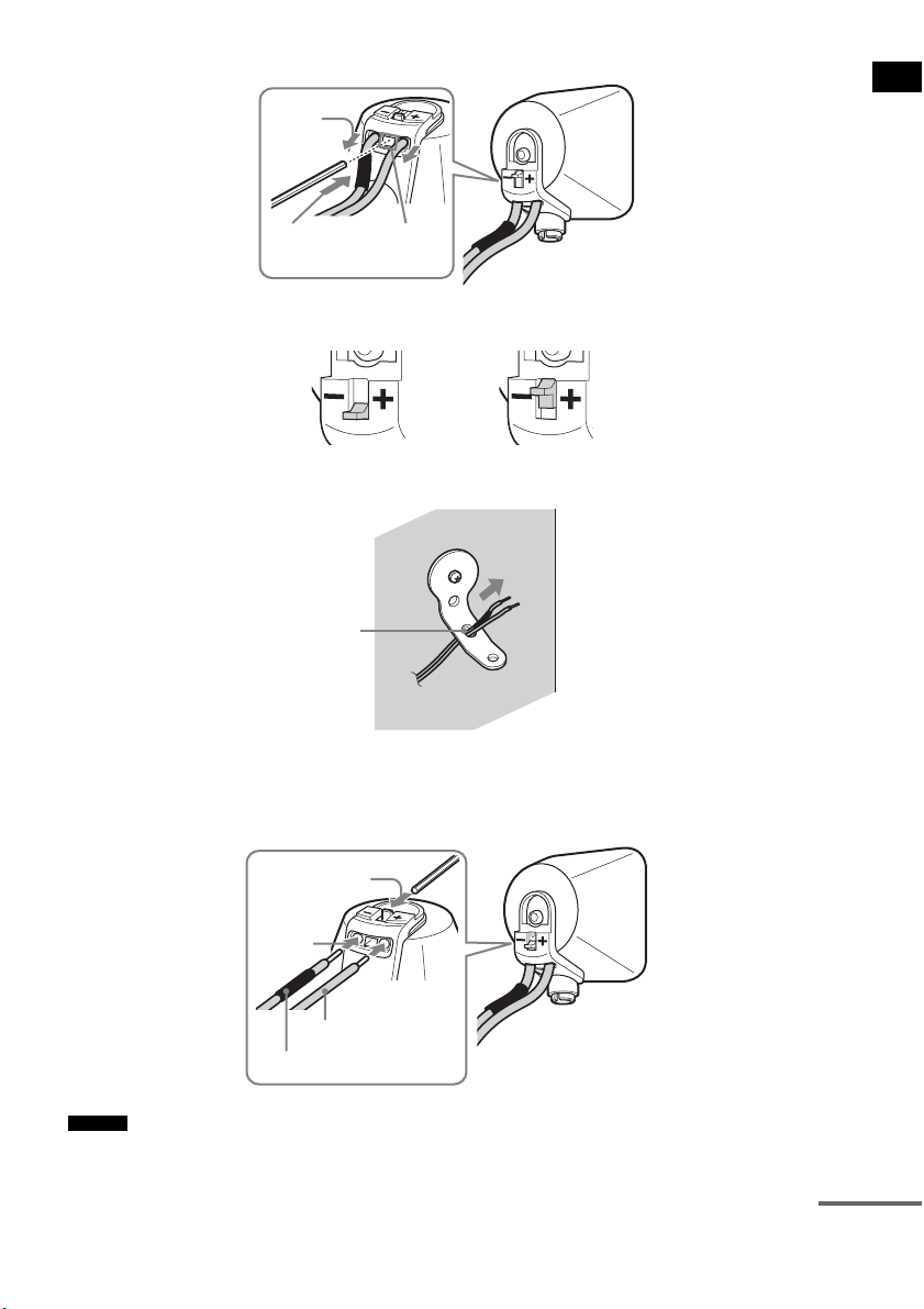
11
ES
Procedimientos iniciales
4 Presione el punto A con la llave suministrada (1) y quite los cables del altavoz (2).
5 Pase los cables del altavoz a través del orificio 3.
6 Vuelva a conectar los cables del altavoz desconectados, de modo que 3/# coincidan
con los terminales de altavoz correspondientes (1) y, a continuación, baje
completamente la palanca (2).
• Si tiene problemas para bajar la palanca, utilice la llave (suministrado).
Consejo
(1)
Cuando la palanca está hacia abajo, los
cables de altavoz están bloqueados.
Cuando la palanca está hacia arriba, los
cables de altavoz se pueden extraer.
(2)
A
3
#
3
(1)
(2)
continúa
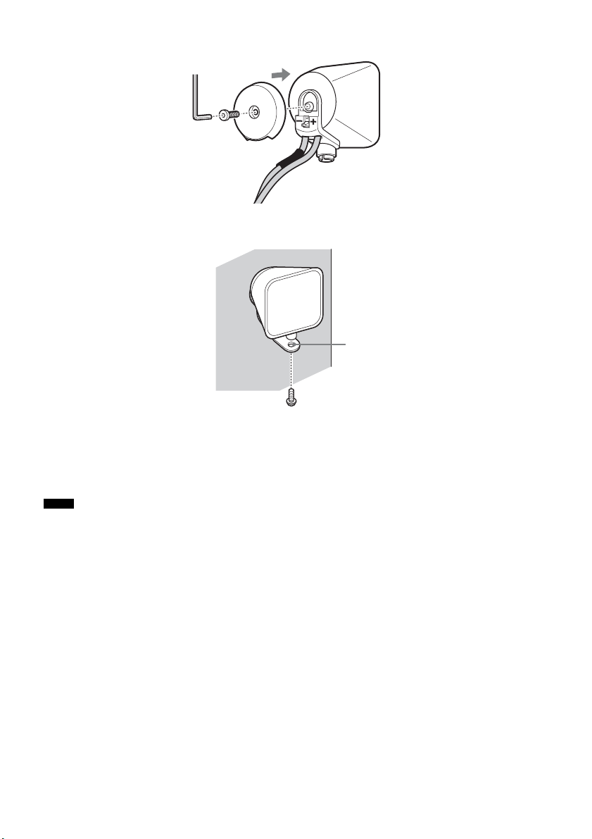
12
ES
7 Vuelva a colocar la tapa posterior con la ayuda de la llave (suministrado).
8 Fije el altavoz al soporte con el tornillo del paso 3 utilizando el orificio 4.
PRECAUCIÓN
• Excepto el altavoz, no cargue peso encima del soporte. De lo contrario, el altavoz podría caerse y provocar lesiones
o daños materiales.
• No se cuelgue del altavoz o del soporte, ya que podría caerle encima y causarle daños.
• Utilice tornillos adecuados al material y la resistencia de la pared. Dado que las paredes de yeso son especialmente
frágiles, debe colocar los tornillos en una viga y fijarlos a la pared. Instale los altavoces en una pared vertical y lisa
que esté reforzada.
• Si tiene dudas en relación con los tornillos adecuados, consúltelo en la ferretería o con un instalador.
• Sony no se responsabiliza de ningún accidente o daño causado por una instalación incorrecta, por la poca resistencia
de una pared o el mal montaje de los tornillos, desastres naturales, etc.
Notas
4

13
ES
Procedimientos iniciales
Acerca del altavoz central
Puede desconectar el receptor de mando a distancia del altavoz central y utilizar los altavoces por
separado.
También puede instalar el receptor de mando a distancia con el altavoz central en una pared.
1 Extraiga el receptor de mando a distancia con un destornillador (+) (no suministrado).
2 Fije el altavoz con el tornillo.
Para utilizar el altavoz central y el receptor de mando a distancia por separado.
Para instalar el receptor de mando a distancia en una pared.
Altavoz central
Soporte de altavoz adicional
(suministrado)
Tornillo del paso 1
Altavoz central
Receptor de mando a distancia
Soporte
Tornillo (+PSW4 × 12)
(suministrado)
continúa
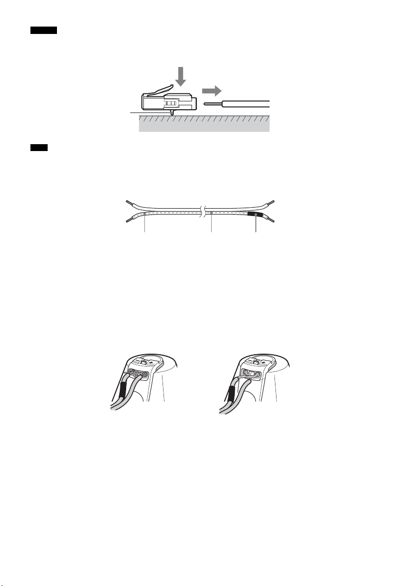
14
ES
• Puede extraer los cables de altavoz del conector. Con el enganche mirando hacia abajo, mantenga presionado el
conector contra una superficie plana (1) y retire los cables de altavoz del conector (2).
• Cuando vuelva a conectar los cables de altavoz al conector, asegúrese de hacer coincidir los cables de altavoz con
los terminales de altavoz correspondientes: 3 con + y # con –. Conecte el cable con letras o líneas blancas (y con
un tubo negro conectado en un lado) a –. Si los cables se colocan al revés, el sonido perderá graves y puede salir
distorsionado.
Para evitar que se produzca un cortocircuito en los altavoces
Si se produce un cortocircuito en los altavoces, el sistema podría dañarse. Para evitarlo, asegúrese de
seguir estas medidas de precaución al conectar los altavoces. Compruebe que el hilo desprotegido de
cada uno de los cables de altavoz no entra en contacto con otro terminal de altavoz ni con el hilo
desprotegido de otro cable de altavoz, tal y como se muestra a continuación.
Consejo
Nota
Enganche
(1)
(2)
# Tubo negroLetras o líneas blancas
El cable de altavoz pelado
toca otro terminal de
altavoz.
Los cables pelados se tocan
entre sí, porque se ha eliminado
demasiado aislamiento.
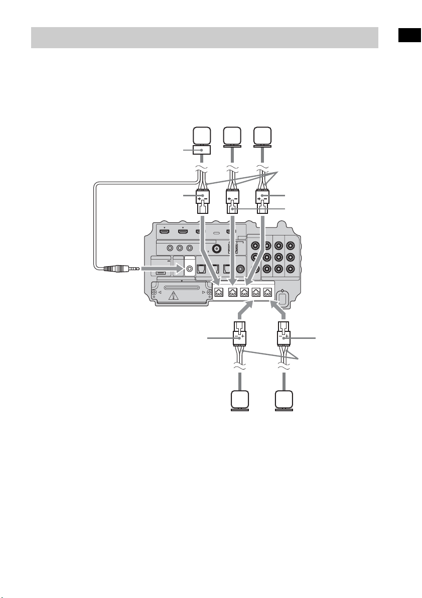
15
ES
Procedimientos iniciales
Conecte los conectores de los cables de altavoz a sus tomas SPEAKER correspondientes. Los
conectores de los cables de altavoz son del mismo color que las tomas que deben conectarse.
Conecte el cable del receptor de mando a distancia a la toma IR-R100.
Paso 2: conexión de los altavoces
IR REMOTE
VIDEO
DMPORT
SPEAKER ONLY FOR SS-IS15
ECM-AC2 IR-R100
ANTENNA
HDMI
IR IN IR OUT1 IR OUT2
FM AM
75
COAXIAL
DC 5V
0.7A MAX
FRONT R FRONT L SUR R SUR LCENTER
BD IN DVD IN SAT IN
SAT IN
ASSIGNABLE
COAXIAL
AUDI O IN
ASSIGNABLE
VIDEO IN
L
R
TV OUT
EZW-T100 DIGITAL
TV IN DVD IN SAT IN
OPTICAL
COMPONENT VIDEO
DVD IN SAT IN
MONITOR
OUT
Y
P
B/
C
B
PR/
C
R
Cables de altavoz
Parte inferior del
altavoz potenciador
de graves
Altavoz
central
Altavoz
frontal
derecho
Altavoz
frontal
izquierdo
Cables de altavoz
Altavoz de
sonido
envolvente
izquierdo
Altavoz de
sonido
envolvente
derecho
Verde
Rojo
Blanco
Gris
Azul
Receptor de mando
a distancia

16
ES
Sony recomienda que conecte los componentes al sistema mediante un cable HDMI.
Con la interfaz HDMI, es posible disfrutar fácilmente de sonido e imágenes de alta calidad.
Sin embargo, es necesario conectar la salida de audio del televisor a la entrada de audio del
sistema con un cable óptico para escuchar el sonido del televisor desde el sistema.
Para obtener más información sobre la función Control por HDMI, consulte “Funciones de
“BRAVIA” Sync” (página 43).
Paso 3a: conexión de los componentes con las tomas HDMI
IR REMOTE
VIDEO
DMPORT
SPEAKER ONLY FOR SS-IS15
ECM-AC2 IR-R100
ANTENNA
HDMI
IR IN IR OUT1 IR OUT2
FM AM
75
COAXIAL
DC 5V
0.7A MAX
FRONT R FRONT L SUR R SUR LCENTER
BD IN DVD IN SAT IN
SAT IN
ASSIGNABLE
COAXIAL
AUDI O IN
ASSIGNABLE
VIDEO IN
L
R
TV OUT
EZW-T100 DIGITAL
TV IN DVD IN SAT IN
OPTICAL
COMPONENT VIDEO
DVD IN SAT IN
MONITOR
OUT
Y
P
B/
C
B
PR/
C
R
Monitor del televisor, proyector, etc.
A Cable HDMI (no suministrado)
B Cable óptico (suministrado)
Señal de
audio/vídeo
Reproductor de Blu-ray Disc
(grabadora), “PlayStation 3”
Señal de
audio/vídeo
Sintonizador vía satélite
Señal de
audio/vídeo
B
A
Señal de
audio/vídeo
Reproductor de DVD
(grabadora)
Señal de
audio
: Flujo de la señal
A
A
A
Parte inferior del
altavoz potenciador
de graves

17
ES
Procedimientos iniciales
• Para obtener más información sobre la conexión de componentes sin tomas HDMI, consulte la página 18.
• La toma HDMI tiene prioridad al conectar el componente al sistema utilizando las tomas de entrada HDMI y otras
tomas de entrada a la vez.
Notas acerca de las conexiones HDMI
• Podrá disfrutar de imágenes con la más alta calidad con un cable HDMI que tenga el logotipo de
HDMI. Sony recomienda utilizar el cable HDMI de Sony.
• Compruebe la configuración del componente conectado si la imagen es de baja calidad o si el
componente no emite audio mediante el cable HDMI.
• Es posible que el componente conectado cancele las señales de audio (frecuencia de muestreo,
longitud de bits, etc.) que se transmiten desde una toma HDMI.
• Es posible que se interrumpa el sonido si se modifican la frecuencia de muestreo o el número de
canales de las señales de emisión de audio del componente en reproducción.
• Si el componente conectado no es compatible con la tecnología de protección de derechos de autor
(HDCP), es posible que la imagen y/o el sonido de la toma HDMI TV OUT aparezca distorsionado
o no se emita.
En este caso, compruebe las especificaciones del componente conectado.
• Sony desaconseja el uso de un cable de conversión HDMI-DVI.
• Independientemente de la entrada que se seleccione para el sistema, las señales de vídeo de la toma
de entrada seleccionadas por última vez se emiten desde la toma HDMI TV OUT.
Notas
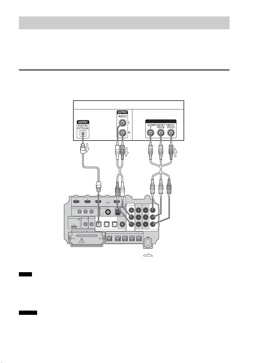
18
ES
Al conectar un reproductor de DVD (grabadora), sintonizador vía satélite o videograbadora sin tomas
HDMI, puede elegir la combinación de conexiones del sistema. Este altavoz potenciador de graves está
equipado con una función de conversión de señales de vídeo. Para obtener más información, consulte
“Función para la conversión de señales de vídeo” (página 30).
Conexión de un monitor de televisor
La imagen de un componente visual conectado al altavoz potenciador de graves puede mostrarse en un
monitor de televisor o un proyector.
• Conecte los componentes de visualización de imágenes, como un televisor o un proyector, a las tomas MONITOR OUT
del altavoz potenciador de graves.
• Asegúrese de encender el altavoz potenciador de graves cuando se emita vídeo o audio de un componente de
reproducción a un televisor mediante el altavoz potenciador de graves. Si el altavoz potenciador de graves está
apagado, no se transmitirá ni señal de vídeo ni de audio.
• Puede volver a asignar la entrada de audio analógica mediante las tomas AUDIO IN ASSIGNABLE. Para obtener
más información, consulte “Reasignación de la entrada de audio analógica” (página 66).
Paso 3b: conexión de los componentes sin las tomas HDMI
Notas
Consejos
IR REMOTE
VIDEO
DMPORT
SPEAKER ONLY FOR SS-IS15
ECM-AC2 IR-R100
ANTENNA
HDMI
IR IN IR OUT1 IR OUT2
FM AM
75
COAXIAL
DC 5V
0.7A MAX
FRONT R FRONT L SUR R SUR LCENTER
BD IN DVD IN SAT IN
SAT IN
ASSIGNABLE
COAXIAL
AUDI O IN
ASSIGNABLE
VIDEO IN
L
R
TV OUT
EZW-T100 DIGITAL
TV IN DVD IN SAT IN
OPTICAL
COMPONENT VIDEO
DVD IN SAT IN
MONITOR
OUT
Y
P
B/
C
B
PR/
C
R
INPUT
Monitor del televisor, proyector, etc.
A Cable óptico (suministrado)
B Cable de audio (no suministrado)
C Cable de vídeo componente (no suministrado)
Señal de vídeo
: Flujo de la señal
Señal de audio
Parte inferior del
altavoz potenciador
de graves
ABC
o
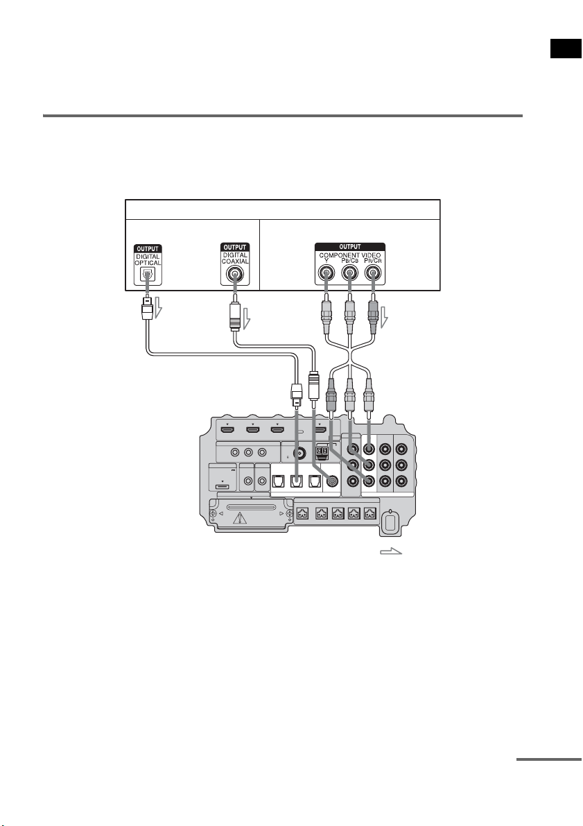
19
ES
Procedimientos iniciales
• Puede visualizar la imagen de entrada seleccionada al conectar la toma MONITOR OUT a un televisor.
• Para emitir el sonido del televisor desde los altavoces conectados al altavoz potenciador de graves, asegúrese de
– conectar las tomas de salida de audio del televisor a las tomas OPTICAL TV IN del altavoz potenciador de
graves.
– apagar el televisor o ponerlo en silencio.
Conexión de un reproductor de DVD (grabadora)
La ilustración siguiente muestra como conectar un reproductor de DVD (grabadora).
Puede reasignar la entrada de audio digital con la toma ASSIGNABLE COAXIAL SAT IN. Para
obtener más información, consulte “Reasignación de la entrada de audio digital” (página 67).
IR REMOTE
VIDEO
DMPORT
SPEAKER ONLY FOR SS-IS15
ECM-AC2 IR-R100
ANTENNA
HDMI
IR IN IR OUT1 IR OUT2
FM AM
75
COAXIAL
DC 5V
0.7A MAX
FRONT R FRONT L SUR R SUR LCENTER
BD IN DVD IN SAT IN
AUDI O IN
ASSIGNABLE
VIDEO IN
L
R
TV OUT
EZW-T100 DIGITAL
TV IN DVD IN SAT IN
OPTICAL
COMPONENT VIDEO
DVD IN SAT IN
MONITOR
OUT
Y
P
B/
C
B
PR/
C
R
SAT IN
ASSIGNABLE
COAXIAL
Reproductor de DVD (grabadora)
A Cable óptico (no suministrado)
B Cable coaxial (no suministrado)
C Cable de vídeo componente (no suministrado)
Señal de vídeo
: Flujo de la señal
Señal de audio
Parte inferior del
altavoz potenciador
de graves
o
AB C
continúa
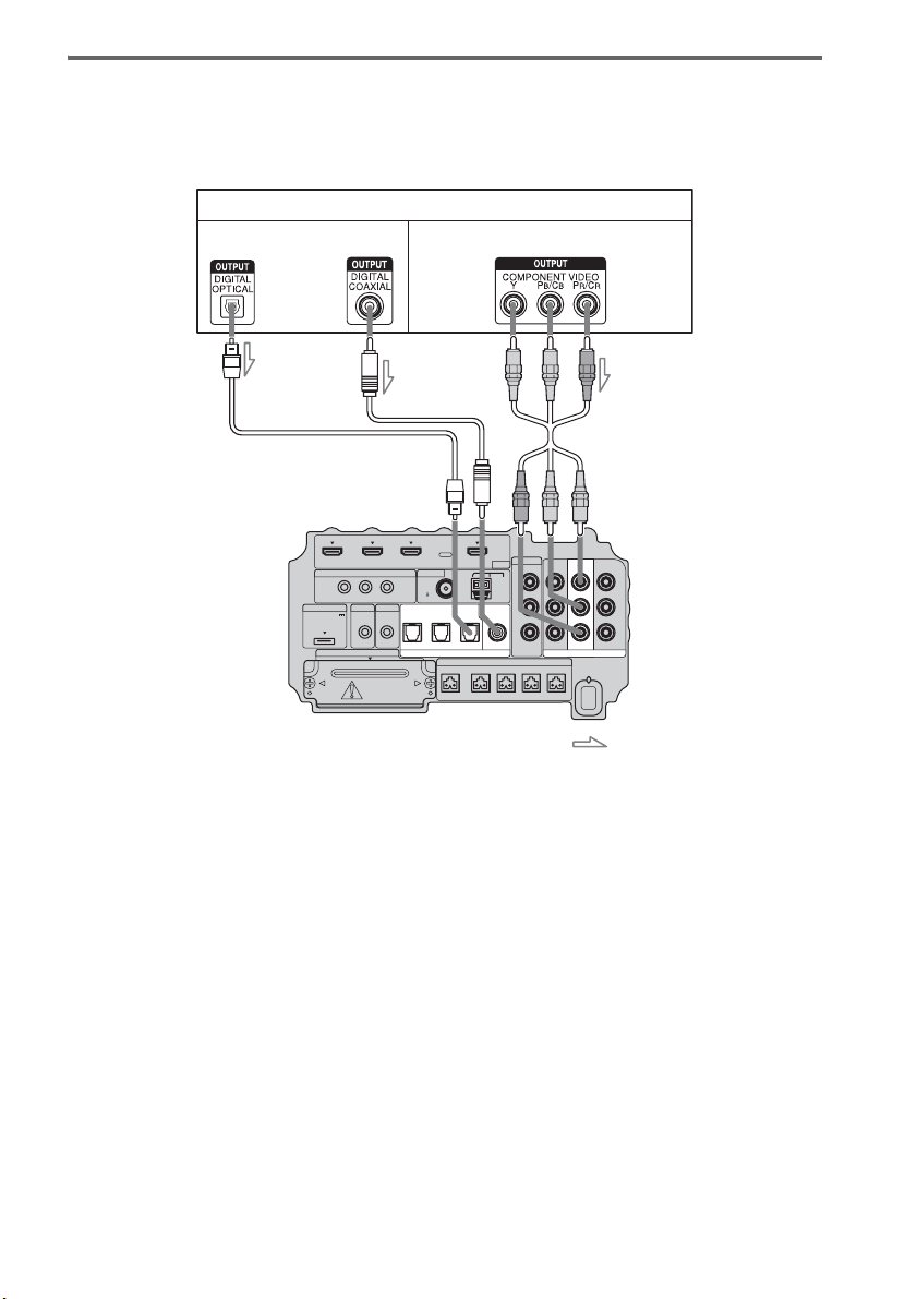
20
ES
Conexión de un sintonizador vía satélite
La ilustración siguiente muestra como conectar un sintonizador vía satélite.
Si el sintonizador vía satélite no dispone de toma OPTICAL OUT, conecte el sistema mediante la toma
COAXIAL SAT IN.
IR REMOTE
VIDEO
DMPORT
SPEAKER ONLY FOR SS-IS15
ECM-AC2 IR-R100
ANTENNA
HDMI
IR IN IR OUT1 IR OUT2
FM AM
75
COAXIAL
DC 5V
0.7A MAX
FRONT R FRONT L SUR R SUR LCENTER
BD IN DVD IN SAT IN
AUDI O IN
ASSIGNABLE
VIDEO IN
L
R
TV OUT
EZW-T100 DIGITAL
TV IN DVD IN SAT IN
OPTICAL
COMPONENT VIDEO
DVD IN SAT IN
MONITOR
OUT
Y
P
B/
C
B
PR/
C
R
SAT IN
ASSIGNABLE
COAXIAL
Sintonizador vía satélite
C
A Cable óptico (no suministrado)
B Cable coaxial (no suministrado)
C Cable de vídeo componente (no suministrado)
Señal de vídeo
: Flujo de la señal
B
Señal de audio
o
A
Parte inferior del
altavoz potenciador
de graves

21
ES
Procedimientos iniciales
Conexión de una videograbadora
La ilustración siguiente muestra cómo conectar un componente que dispone de tomas analógicas como
las de una videograbadora.
IR REMOTE
VIDEO
DMPORT
SPEAKER ONLY FOR SS-IS15
ECM-AC2 IR-R100
ANTENNA
HDMI
IR IN IR OUT1 IR OUT2
FM AM
75
COAXIAL
DC 5V
0.7A MAX
FRONT R FRONT L SUR R SUR LCENTER
BD IN DVD IN SAT IN
AUDI O IN
ASSIGNABLE
VIDEO IN
L
R
TV OUT
EZW-T100 DIGITAL
TV IN DVD IN SAT IN
OPTICAL
COMPONENT VIDEO
DVD IN SAT IN
MONITOR
OUT
Y
P
B/
C
B
PR/
C
R
SAT IN
ASSIGNABLE
COAXIAL
Videograbadora
A
A Cable de audio (no suministrado)
B Cable de vídeo (no suministrado)
Señal de vídeo
: Flujo de la señal
B
Señal
de
audio
Parte inferior del
altavoz potenciador
de graves
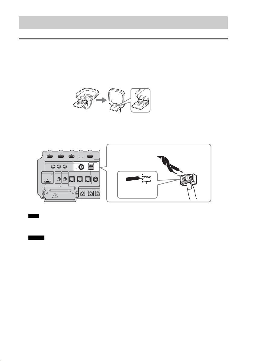
22
ES
Conexión de la antena cerrada de AM
La forma y la longitud de la antena están diseñadas para recibir señales AM. No desmonte ni enrolle la
antena.
1 Extraiga solamente la parte cerrada del soporte de plástico.
2 Instale la antena cerrada de AM.
3 Conecte los cables a los terminales de la antena de AM.
Los cables pueden conectarse a cualquier terminal.
• No coloque la antena cerrada de AM cerca del sistema o de otro componente de audio o vídeo, ya que podría
generar ruidos.
• Ajuste la dirección de la antena cerrada de AM para obtener un sonido mejor.
4 Tire de la antena cerrada de AM suavemente para asegurarse de que está bien
conectada.
Paso 4: conexión de la antena
Nota
Consejo
IR REMOTE
DMPORT
SPEAKER ONLY
F
ECM-AC2 IR-R100
ANTENNA
HDMI
IR IN IR OUT1 IR OUT2
FM AM
75
COAXIAL
DC 5V
0.7A MAX
FRONT R FRONT
L
CENTER
BD IN DVD IN SAT IN
SAT IN
ASSIGNABLE
COAXIAL
A
TV OUT
EZW-T100 DIGITAL
TV IN DVD IN SAT IN
OPTICAL
Insértelo hasta
este punto.
Presione el fijador del terminal para insertar los
cables.
Parte inferior del altavoz
potenciador de graves
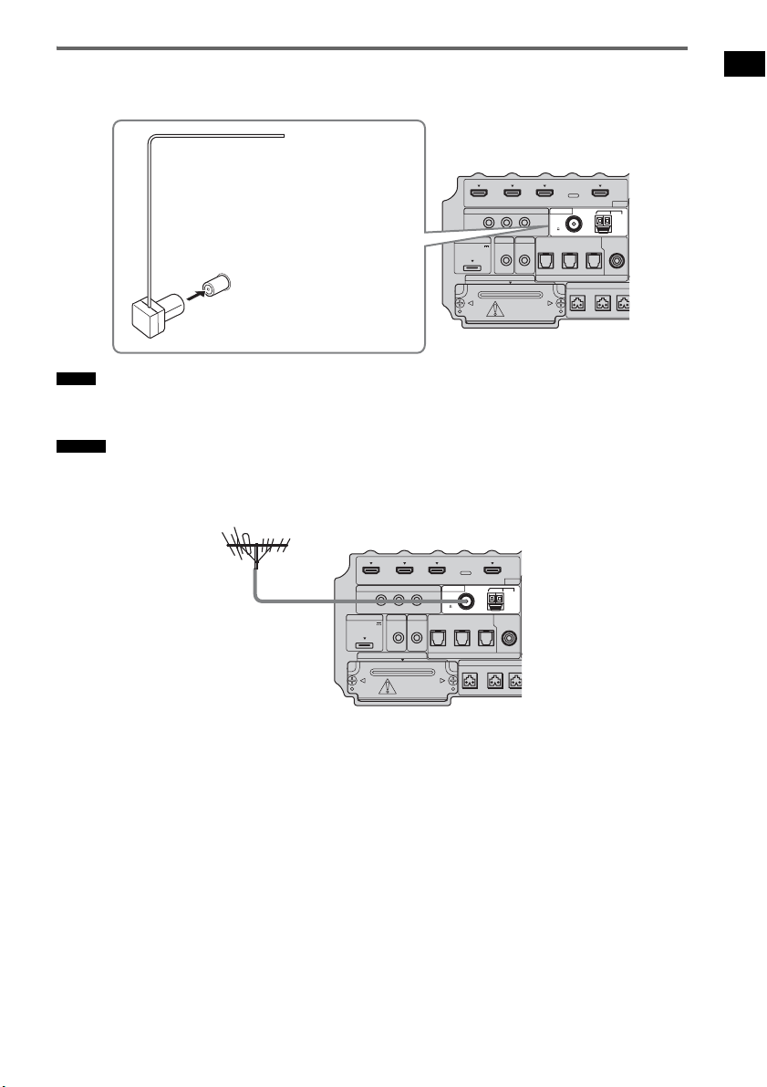
23
ES
Procedimientos iniciales
Conexión de la antena monofilar de FM
Conecte la antena monofilar de FM a la toma FM 75 Ω COAXIAL.
• Asegúrese de extender totalmente la antena monofilar de FM.
• Tras conectar la antena monofilar de FM, manténgala siempre en posición horizontal.
• Si la recepción de FM no es buena, utilice un cable coaxial de 75 ohmios (no suministrado) para conectar el altavoz
potenciador de graves a una antena de FM exterior, tal y como se muestra a continuación.
Notas
Consejo
IR REMOTE
DMPORT
SPEAKER ONLY
F
ECM-AC2 IR-R100
ANTENNA
HDMI
IR IN IR OUT1 IR OUT2
FM AM
75
COAXIAL
DC 5V
0.7A MAX
FRONT R FRONT
L
CENTER
BD IN DVD IN SAT IN
SAT IN
ASSIGNABLE
COAXIAL
A
TV OUT
EZW-T100 DIGITAL
TV IN DVD IN SAT IN
OPTICAL
Antena monofilar de FM
(suministrado)
Toma FM 75 Ω COAXIAL
Parte inferior del altavoz
potenciador de graves
IR REMOTE
DMPORT
SPEAKER ONLY
F
ECM-AC2 IR-R100
ANTENNA
HDMI
IR IN IR OUT1 IR OUT2
FM AM
75
COAXIAL
DC 5V
0.7A MAX
FRONT R FRONT
L
CENTER
BD IN DVD IN SAT IN
SAT IN
ASSIGNABLE
COAXIAL
A
TV OUT
EZW-T100 DIGITAL
TV IN DVD IN SAT IN
OPTICAL
Antena de FM exterior
Parte inferior del altavoz
potenciador de graves

24
ES
Antes de conectar el cable de alimentación de ca
del altavoz potenciador de graves a una toma de
pared, conecte todos los altavoces al altavoz
potenciador de graves (página 15).
• Tras conectar el cable de alimentación de ca, espere
unos 20 segundos antes de encender el aparato
presionando "/1.
El altavoz potenciador de graves incorpora la
tecnología D.C.A.C. (Autocalibración de cine
digital), que permite realizar la calibración
automáticamente, de la forma siguiente:
• Compruebe la conexión entre cada altavoz y el
altavoz potenciador de graves.
• Ajuste el nivel del altavoz.
• Mida la distancia entre cada altavoz y la
posición de escucha.
• Mida las características de frecuencia.*
* El resultado de la medición no se utiliza en señales
con una frecuencia de muestreo superior a los 96
kHz.
El sistema D.C.A.C. está diseñado para obtener
un buen balance de sonido en la habitación. Sin
embargo, puede ajustar los niveles y el balance
de los altavoces manualmente, según sus
preferencias. Para obtener más información,
consulte “Configuración del nivel de los
altavoces” (página 60).
Paso 5: conexión del cable
de alimentación de ca
Nota
Cable de
alimentación de ca
Parte posterior del altavoz
potenciador de graves
Hacia la toma de
pared
Paso 6: calibración de los
ajustes adecuados de
forma automática
(Autocalibración)

25
ES
Procedimientos iniciales
Antes de realizar la
autocalibración
Antes de realizar la autocalibración, configure y
conecte los altavoces (página 15).
• La toma ECM-AC2 se utiliza solamente para el
micrófono de calibración (suministrado). No
conecte otros micrófonos a esta toma. De lo
contrario, podría dañar el altavoz potenciador
de graves y el micrófono de calibración.
• Durante la calibración, el sonido que sale de los
altavoces es muy alto. Procure que el sonido no
moleste a niños o a los vecinos.
• Realice la autocalibración en un entorno
tranquilo, para evitar las interferencias del
ruido y obtener una medición más precisa.
• Si hay obstáculos entre el micrófono de
calibración y los altavoces, la calibración no
podrá realizarse correctamente. Elimine todos
los obstáculos de la zona de medición para
evitar cualquier error.
• Si la función de desactivación del sonido está activada
durante la autocalibración, se apagará
automáticamente.
• Al utilizar el producto S-AIR, desconecte los
auriculares.
1 Conecte el micrófono de calibración
(suministrado) a la toma ECM-AC2 del
altavoz potenciador de graves.
2 Ajuste el micrófono de calibración.
Coloque el micrófono de calibración en la
posición de escucha. También puede utilizar
un taburete o un trípode, para que el
micrófono de calibración esté a la misma
altura que el oído.
• La parte frontal de cada altavoz debe estar orientada
hacia el micrófono de calibración. De este modo, la
medición será más precisa.
Notas
Consejo
IR REMOTE
VIDEO
DMPORT
SPEAKER ONLY FOR SS-IS15
ECM-AC2 IR-R100
ANTENNA
HDMI
IR IN IR OUT1 IR OUT2
FM AM
75
COAXIAL
DC 5V
0.7A MAX
FRONT R FRONT L SUR R SUR LCENTER
BD IN DVD IN SAT IN
SAT IN
ASSIGNABLE
COAXIAL
AUDI O IN
ASSIGNABLE
VIDEO IN
L
R
TV OUT
EZW-T100 DIGITAL
TV IN DVD IN SAT IN
OPTICAL
COMPONENT VIDEO
DVD IN SAT IN
MONITOR
OUT
Y
P
B/
C
B
PR/
C
R
Parte inferior del altavoz
potenciador de graves
Hacia la toma
ECM-AC2
Micrófono de
calibración
continúa
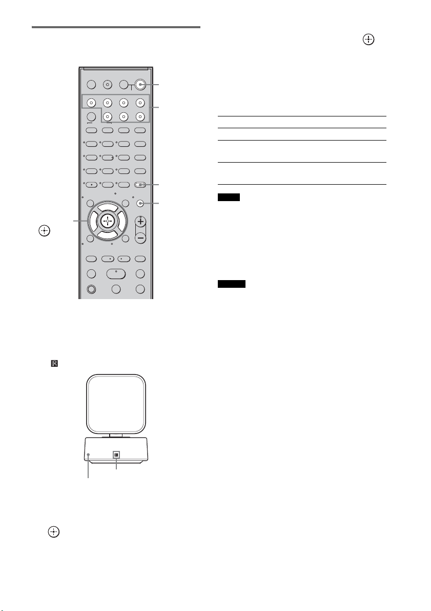
26
ES
Realización de la
autocalibración
1 Presione ?/1.
El sistema se enciende.
2 Pulse AMP MENU.
Oriente el mando a distancia hacia el sensor
( ) del receptor de mando a distancia.
3 Pulse x/X varias veces hasta que
aparezca “A. CAL MENU” en el visor del
panel superior y, a continuación, pulse
o c.
4 Pulse x/X para seleccionar “A. CAL
START” y, a continuación, pulse .
La autocalibración empezará después de la
cuenta atrás.
El proceso de medición tarda unos 30 segundos
en completarse.
La tabla siguiente muestra la imagen del visor
cuando empieza la medición.
• Si aparece “PHONES”, no podrá realizar la
autocalibración. Desconecte los auriculares del
producto S-AIR que utilice y, seguidamente, vuelva a
iniciar la autocalibración.
• Si aparece “CHECK MIC”, no podrá realizar la
autocalibración. Conecte el micrófono de calibración
y vuelva a iniciar la autocalibración.
• Cuando empiece la autocalibración:
– Sitúese a una cierta distancia de los altavoces y de la
posición de escucha, para evitar errores en la
medición. El motivo es que los altavoces emiten
señales de prueba durante la medición.
– Evite ocasionar ruidos, para obtener así una
medición más precisa.
Para cancelar la autocalibración
La función de autocalibración se cancelará si
realiza alguna de las acciones siguientes durante
el proceso de medición:
– Pulsar MUTING.
– Pulsar los botones de entrada del mando a
distancia o bien INPUT SELECTOR en el
altavoz potenciador de graves.
– Cambiar el nivel de volumen.
123
46
78
0
ENTER
9
TV INPUTTHEATER
TV
?/1
AV
?/1
TV BD DVD SAT
TOP MENU MENU
BD/DVD
RETURN/EXIT
TV
REPLAY ADVANCE
F1 F2
AMP MENU
CLEAR
DISPLAY
MUTING
TONE
TUNING - TUNING +
NIGHT
MODE
GUIDE
FAVORITEWIDEPICTUREJUMP
DMPORTTUNER/BANDVIDEO
SOUND FIELD
?/1
TV CH -
PRESET -
TV CH +
PRESET +
F
Gg
f
.
HmM
Xx
<
<
>
5
SYSTEM STANDBY
MENU/HOME
TOOLS/
OPTIONS
TV VOL
MASTER VOL
C, X, x, c,
?/1
AMP
MENU
Botones de
entrada
MUTING
Receptor de mando a distancia
Sensor remoto
Medición de Visor
Presencia de altavoces TONE
Ganancia, distancia y respuesta de
frecuencia de altavoces
T.S.P.
Ganancia y distancia de altavoz
potenciador de graves
SUBWOOFER
Notas
Consejo

27
ES
Procedimientos iniciales
Confirmar/guardar los
resultados de la medición
1 Confirme el resultado de la medición.
Cuando termine la medición, sonará un
pitido y el resultado de la medición
aparecerá en el visor del panel superior.
• Tras aparecer “SAVE EXIT” durante unos 50
segundos, el resultado de la medición se guarda
automáticamente sin necesidad de realizar otras
acciones.
2 Pulse x/X varias veces para
seleccionar el elemento que desee y, a
continuación, pulse o c. Para
regresar, pulse C o RETURN.
3 Guarde el resultado de la medición.
Seleccione “SAVE EXIT” en el paso 2 y, a
continuación, pulse .
El resultado de la medición quedará
guardado.
Si aparecen códigos de error
Intente aplicar las soluciones y vuelva a realizar
la autocalibración.
Al seleccionar “WRN CHECK”
Si hay una advertencia sobre el resultado de la
medición, aparece información detallada.
Elemento Explicación
SAVE EXIT Guarda los resultados de la
medición y sale del proceso de
ajuste.
WRN CHECK Muestra avisos relacionados
con los resultados de la
medición. Consulte “Al
seleccionar “WRN CHECK””
(página 27).
DIST INFO Muestra el resultado de la
medición de la distancia del
altavoz.
LEVEL INFO Muestra el resultado de la
medición del nivel del altavoz.
EXIT Sale del proceso de ajuste sin
guardar los resultados de la
medición.
Nota
Elemento Explicación
ERROR 32 • La entrada de sonido del
micrófono de calibración está
fuera del rango aceptable.
• El micrófono de calibración o
el altavoz potenciador de
graves pueden estar dañados.
Póngase en contacto con su
distribuidor Sony o con un
centro de asistencia autorizado
de Sony.
ERROR F 33 Los altavoces frontales no están
conectados.
Compruebe que los altavoces
frontales estén bien conectados.
ERROR SR 33 El altavoz de sonido envolvente
izquierdo o derecho no está
conectado.
Compruebe que los altavoces de
sonido envolvente estén bien
conectados.
ERROR SW 33 El altavoz potenciador de
graves puede estar dañado.
Póngase en contacto con su
distribuidor Sony o con un
centro de asistencia autorizado
de Sony.
Código de
advertencia
Explicación
WARNING 40 La autocalibración ha
terminado. Sin embargo, el
nivel de ruido es elevado. Puede
volver a realizar la
autocalibración, aunque la
medición no pueda efectuarse
en todos los entornos. Intente
realizar la autocalibración en un
entorno tranquilo.
WARNING 41
WARNING 42
La entrada de sonido del
micrófono de calibración está
fuera del rango aceptable. La
distancia entre el micrófono de
calibración y los altavoces es
demasiado estrecha. Apártelos
y trate de realizar la
Autocalibración.
continúa

28
ES
Al seleccionar “DIST INFO” o
“LEVEL INFO”
Puede comprobar la distancia del altavoz o el
nivel del altavoz.
• Los resultados de la medición de un altavoz no
aparecerán si el altavoz potenciador de graves no
reconoce que el altavoz está conectado.
Cuando haya terminado
Desconecte el micrófono de calibración del
altavoz potenciador de graves.
• Si ha modificado la posición de los altavoces, Sony
recomienda realizar de nuevo la autocalibración para
disfrutar del sonido envolvente.
Eliminación del resultado de
la autocalibración
Puede eliminar el resultado de la
Autocalibración. Si no hay datos guardados, no
podrá eliminar los resultados.
1 Pulse AMP MENU.
2 Pulse x/X varias veces hasta que
aparezca “A.CAL MENU” y, a
continuación, pulse o c.
3 Pulse x/X varias veces hasta que
aparezca “A.CAL CLEAR” y, a
continuación, pulse o c.
4 Pulse x/X para seleccionar “YES” y, a
continuación, pulse .
El resultado guardado se eliminará.
Los ajustes de la distancia y el nivel de los
altavoces regresan a sus valores
predeterminados.
WARNING 43 No pueden detectarse la
distancia y la posición del
altavoz potenciador de graves.
Puede que sea por culpa del
ruido. Intente realizar la
autocalibración en un entorno
tranquilo.
NO WARNING No existe información sobre
advertencias.
Nota
Nota
Código de
advertencia
Explicación

29
ES
Procedimientos iniciales
En función de los ajustes de salida de audio del
componente conectado, puede que el sonido se
emita solo en formato de 2 canales. En este caso,
ajuste el componente conectado para que emita
el sonido en formato de sonido multicanal (PCM,
DTS, Dolby Digital). Para obtener más
información sobre los ajustes de la salida de
audio, consulte el manual de instrucciones del
componente conectado.
Configuración de la salida
de sonido del componente
conectado
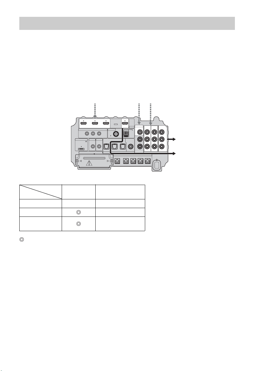
30
ES
El altavoz potenciador de graves está equipado con una función de conversión de señales de vídeo.
Las señales de vídeo y de vídeo componente pueden emitirse como señales de vídeo HDMI y las
señales de vídeo convertidas solo pueden salir por la toma HDMI TV OUT. Consulte la ilustración
siguiente.
En la tabla de conversión de entrada/salida de vídeo del altavoz
potenciador de graves
: señales de vídeo convertidas y emitidas a través del conversor de vídeo.
a : se emite el mismo tipo de señal que la señal de entrada. Las señales de vídeo no se convierten.
X : no se emiten señales de vídeo.
Notas sobre la conversión de señales de vídeo
• Si se convierten señales de vídeo de, por ejemplo, una videograbadora en el altavoz potenciador de
graves y posteriormente se emiten al televisor, en función de la condición de la salida de señal de
vídeo, puede que la imagen en la pantalla del televisor aparezca distorsionada horizontalmente, o que
no aparezca ninguna imagen.
• Las señales de vídeo HDMI no pueden convertirse a señales de vídeo componente.
• Las señales de vídeo convertidas se emiten solo por la toma HDMI OUT. No pueden emitirse a través
de otras tomas de vídeo.
• Si reproduce una videograbadora con un circuito de mejora de la imagen, como TBC, puede que las
imágenes aparezcan distorsionadas o que no se emitan. En este caso, desactive la función del circuito
de mejora de imagen.
Función para la conversión de señales de vídeo
HDMI TV OUT
COMPONENT VIDEO
MONITOR OUT
HDMI IN A a X
VIDEO IN B X
COMPONENT
VIDEO IN C
a
IR REMOTE
DMPORT
SPEAKER ONLY FOR SS-IS15
ECM-AC2 IR-R100
ANTENNA
IR IN IR OUT1 IR OUT2
FM AM
75
COAXIAL
DC 5V
0.7A MAX
FRONT R FRONT L SUR R SUR LCENTER
AUDI O IN
ASSIGNABLE
L
R
EZW-T100 DIGITAL
TV IN DVD IN SAT IN
OPTICAL
COMPONENT VIDEO
DVD IN SAT IN
MONITOR
OUT
Y
P
B/
C
B
PR/
C
R
SAT IN
ASSIGNABLE
COAXIAL
VIDEO
VIDEO IN
HDMI
BD IN DVD IN SAT IN TV OUT
Señales de entrada
ABC
C
ABC
Señales de salidaParte inferior
del altavoz
potenciador
de graves
Toma INPUT
Toma OUTPUT
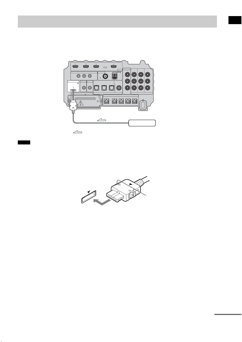
31
ES
Procedimientos iniciales
Para conectar el adaptador DIGITAL MEDIA PORT
Puede disfrutar del sonido de un componente conectado al altavoz potenciador de graves mediante un
adaptador DIGITAL MEDIA PORT.
• No conecte ni desconecte el adaptador DIGITAL MEDIA PORT con el sistema encendido.
• Al conectar el adaptador DIGITAL MEDIA PORT, asegúrese de que el conector está insertado con la flecha
apuntando hacia la flecha de la toma DMPORT. Para desconectar el adaptador DIGITAL MEDIA PORT, mantenga
pulsado
A y tire del conector.
Conexión de otros componentes
Notas
IR REMOTE
VIDEO
DMPORT
SPEAKER ONLY FOR SS-IS15
ECM-AC2 IR-R100
ANTENNA
HDMI
IR IN IR OUT1 IR OUT2
FM AM
75
COAXIAL
DC 5V
0.7A MAX
FRONT R FRONT L SUR R SUR LCENTER
BD IN DVD IN SAT IN
SAT IN
ASSIGNABLE
COAXIAL
AUDI O IN
ASSIGNABLE
VIDEO IN
L
R
TV OUT
EZW-T100 DIGITAL
TV IN DVD IN SAT IN
OPTICAL
COMPONENT VIDEO
DVD IN SAT IN
MONITOR
OUT
Y
P
B/
C
B
PR/
C
R
Adaptador DIGITAL MEDIA PORT
: Flujo de la señal
Parte inferior del
altavoz potenciador
de graves
A
continúa

32
ES
Para utilizar el sistema inalámbrico
El sistema es compatible con la función S-AIR, que permite transmitir sonido entre el altavoz
potenciador de graves y un producto S-AIR (no suministrado). Al adquirir el producto S-AIR, deberá
establecer la transmisión de sonido.
Para obtener más información, consulte la página 68.
PRECAUCIÓN
• No es necesario abrir la tapa de la ranura hasta que deba utilizarse el producto S-AIR.
IR REMOTE
VIDEO
DMPORT
SPEAKER ONLY FOR SS-IS15
ECM-AC2 IR-R100
ANTENNA
HDMI
IR IN IR OUT1 IR OUT2
FM AM
75
COAXIAL
DC 5V
0.7A MAX
FRONT R FRONT L SUR R SUR LCENTER
BD IN DVD IN SAT IN
SAT IN
ASSIGNABLE
COAXIAL
AUDI O IN
ASSIGNABLE
VIDEO IN
L
R
TV OUT
EZW-T100 DIGITAL
TV IN DVD IN SAT IN
OPTICAL
COMPONENT VIDEO
DVD IN SAT IN
MONITOR
OUT
Y
P
B/
C
B
PR/
C
R
Tapa de la ranura
Parte inferior del
altavoz potenciador
de graves
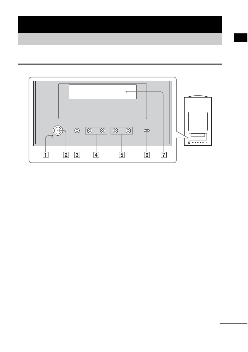
33
ES
Opciones de reproducción
Para obtener más información, consulte las páginas indicadas entre paréntesis.
Panel superior
A POWER / ACTIVE STANDBY
Verde: El sistema se enciende.
Naranja: La función Control por HDMI o S-AIR STANDBY MODE está activada mientras el
sistema está apagado.
Sin luz: El sistema está apagado y las funciones Control por HDMI y S-AIR STANDBY MODE
no están activadas.
B ?/1 (encendido/en espera)
Pulse este botón para encender y apagar el sistema.
C INPUT SELECTOR
Pulse este botón para seleccionar la fuente de entrada que desea reproducir.
D PRESET –/+
Pulse este botón para pasar a la emisora de radio memorizada anterior o siguiente.
E VOLUME –/+
Pulse este botón para ajustar el nivel de volumen.
F S-AIR
Verde: El transmisor S-AIR (no suministrado) está insertado en el altavoz potenciador de graves
y el sistema establece la transmisión de sonido.
Sin luz: El sistema no establece la transmisión de sonido mediante la función S-AIR.
G Visor del panel superior
Compruebe el estado del sistema.
Opciones de reproducción
Índice de componentes y controles
-
VOLUME +
-
PRESET +INPUT SELECTOR
POWER/
ACTIVE STANDBY
continúa
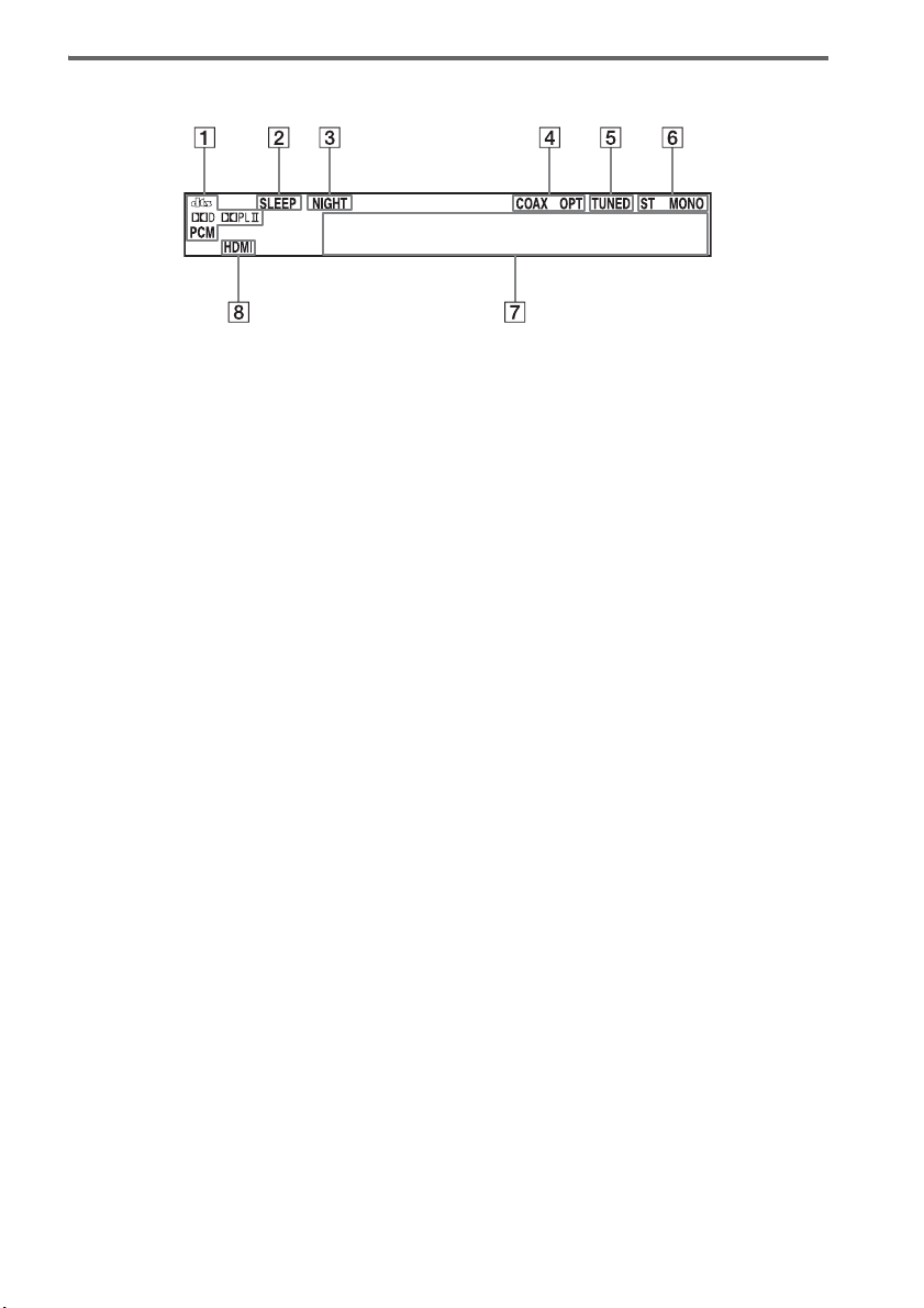
34
ES
Acerca de las indicaciones del visor del panel superior
A Se enciende en función de las señales de entrada de audio.
B SLEEP (65)
Parpadea cuando la función de temporizador de apagado se encuentra activa.
C NIGHT (42)
Se enciende cuando el modo nocturno está activado.
D COAX/OPT
Se enciende en función de la señal coaxial u óptica de entrada.
E TUNED (48)
Se enciende cuando se recibe una emisora de radio.
F ST/MONO (50)
Se enciende en función de si la radio está en estado estéreo o monoaural.
G Muestra el estado del sistema.
Radiofrecuencia, campo acústico, etc.
H HDMI (16, 78)
Se ilumina al utilizar un componente HDMI.
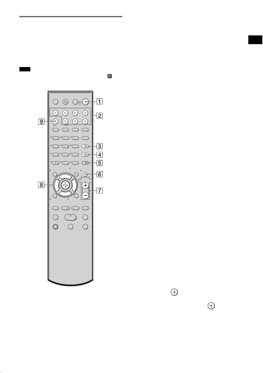
35
ES
Opciones de reproducción
Mando a distancia
A continuación se describen los botones
únicamente para el funcionamiento del
amplificador. Consulte la página 52 para saber
qué botones se utilizan en los componentes
conectados.
• Oriente el mando a distancia hacia el sensor ( ) del
receptor de mando a distancia.
* Los botones 5, H y VOL + disponen de un punto
táctil. Utilice los puntos táctiles como guía durante el
uso del mando a distancia.
A ?/1 (encendido/en espera)
Pulse este botón para encender y apagar el
sistema.
Para ahorrar energía en el modo de
espera
Pulse ?/1 mientras se enciende el sistema.
Para entrar en el modo de ahorro de energía,
asegúrese de que el sistema se encuentra en
el estado siguiente.
– “CTRL: HDMI” en “CTRL OFF”
(página 43).
– “S-AIR STBY” en “STBY OFF”
(página 75).
Para cancelar el modo de espera, pulse
?/1
una vez.
B Botones de entrada
Pulse uno de los botones para seleccionar el
componente que desea utilizar.
Los botones están asignados de fábrica para
controlar componentes Sony. Puede
modificar los ajustes de fábrica de los
botones de entrada en función de los
componentes de su sistema. Para obtener
más información, consulte “Modificación
de las asignaciones de los botones de
entrada del mando a distancia” (página 55).
C TONE
Pulse este botón para ajustar el nivel de
graves, medios y agudos (página 41).
D NIGHT MODE
Pulse este botón para disfrutar de efectos de
sonido al ver películas de noche (página 42).
E AMP MENU
Pulse este botón para que aparezca el menú
del siste (página 56).
F MUTING
Pulse este botón para desactivar el sonido.
G MASTER VOL +/–
Pulse este botón para ajustar el volumen.
H C, X, x, c o
Pulse C, X, x o c para seleccionar los
ajustes. A continuación, pulse para
introducir la selección.
I SOUND FIELD
Pulse este botón para seleccionar el campo
acústico (página 39).
Nota
123
46
78
0
ENTER
9
TV INPUTTHEATER
TV
?/1
AV
?/1
TV BD DVD SAT
TOP MENU MENU
BD/DVD
RETURN/EXIT
TV
REPLAY ADVANCE
F1 F2
AMP MENU
CLEAR
DISPLAY
MUTING
TONE
TUNING - TUNING +
NIGHT
MODE
GUIDE
FAVORITEWIDEPICTUREJUMP
DMPORTTUNER/BANDVIDEO
SOUND FIELD
?/1
TV CH -
PRESET -
TV CH +
PRESET +
F
Gg
f
.
HmM
Xx
<
<
>
5
SYSTEM STANDBY
MENU/HOME
TOOLS/
OPTIONS
TV VOL
MASTER VOL
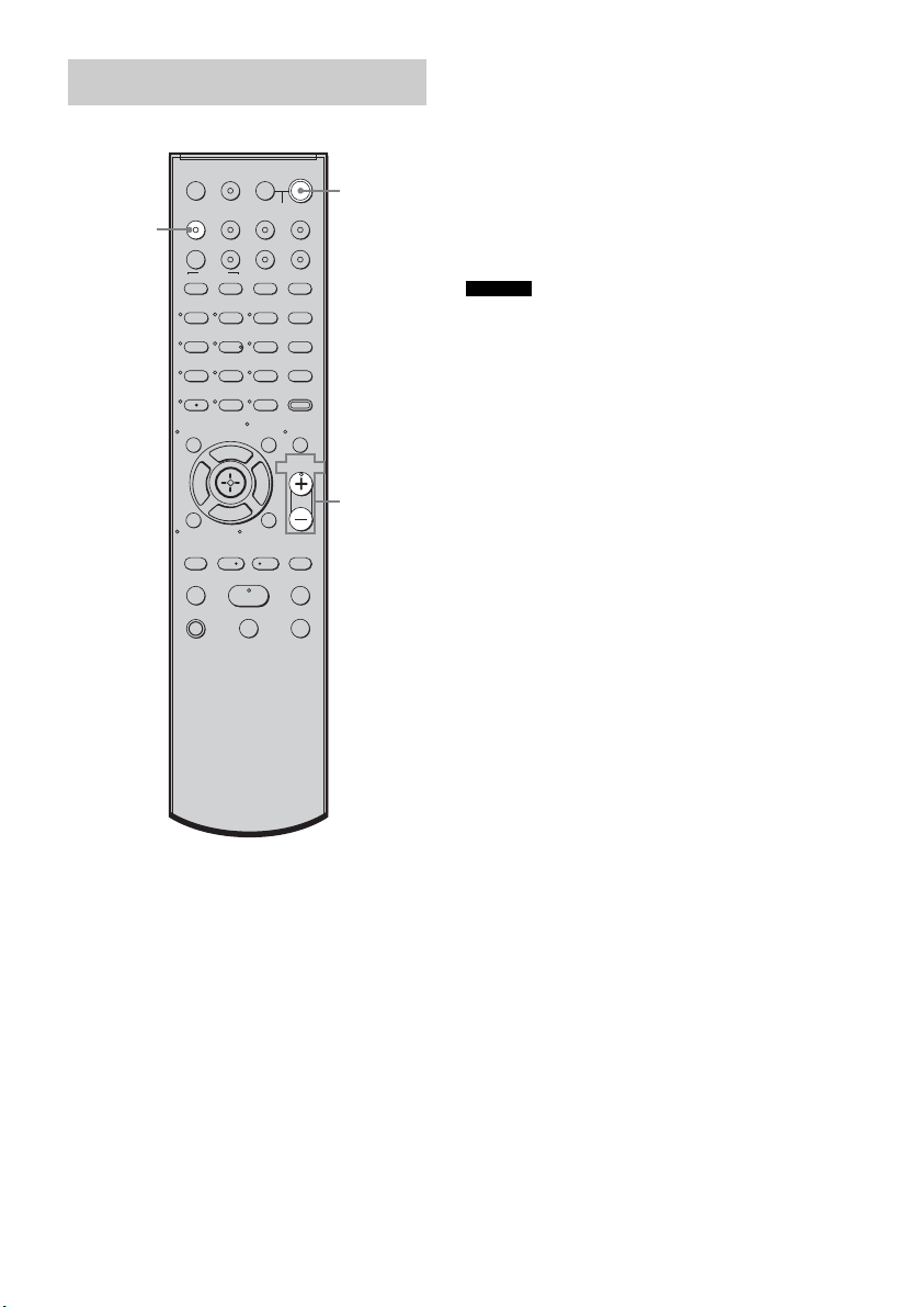
36
ES
1 Encienda el televisor y elija un
programa.
Para obtener más información, consulte el
manual de instrucciones del televisor.
2 Encienda el sistema.
3 Pulse TV (blanco) en el mando a
distancia.
4 Ajuste el volumen del sistema.
• Al conectar un televisor Sony, la entrada de audio del
televisor cambia y la imagen del sintonizador del
televisor aparece en la pantalla del televisor
automáticamente pulsando el botón TV (blanco). Para
cambiar este ajuste, consulte “Modificación de las
asignaciones de los botones de entrada del mando a
distancia” (página 55).
• Es posible que el sonido se emita desde el altavoz del
televisor. En tal caso, ajuste el volumen del altavoz
del televisor al mínimo.
Ver la televisión
123
46
78
0
ENTER
9
TV INPUTTHEATER
TV
?/1
AV
?/1
TV BD DVD SAT
TOP MENU MENU
BD/DVD
RETURN/EXIT
TV
REPLAY ADVANCE
F1 F2
AMP MENU
CLEAR
DISPLAY
MUTING
TONE
TUNING - TUNING +
NIGHT
MODE
GUIDE
FAVORITEWIDEPICTUREJUMP
DMPORTTUNER/BANDVIDEO
SOUND FIELD
?/1
TV CH -
PRESET -
TV CH +
PRESET +
F
Gg
f
.
HmM
Xx
<
<
>
5
SYSTEM STANDBY
MENU/HOME
TOOLS/
OPTIONS
TV VOL
MASTER VOL
?/1
MASTER
VOL +/–
TV
(blanco)
Consejos
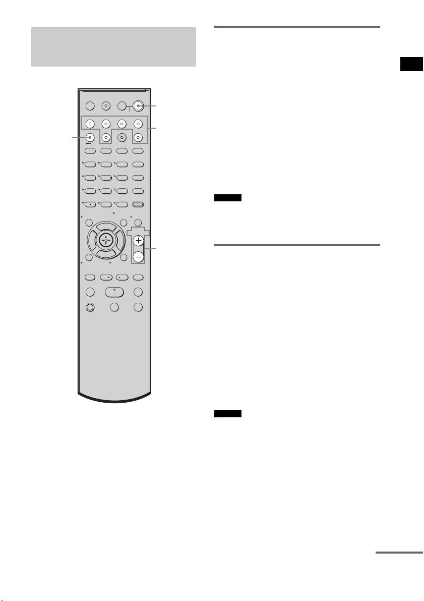
37
ES
Opciones de reproducción
Uso del sintonizador vía
satélite
1 Encienda el televisor.
Para obtener más información, consulte el
manual de instrucciones del televisor.
2 Encienda el sintonizador vía satélite y
el sistema.
3 Pulse SAT en el mando a distancia.
4 Cambie la entrada del televisor.
Para obtener más información, consulte el
manual de instrucciones del televisor.
5 Ajuste el volumen del sistema.
• Es posible que el sonido se emita desde el altavoz del
televisor. En tal caso, ajuste el volumen del altavoz
del televisor al mínimo.
Uso de Blu-ray Disc, DVD o
“PlayStation 3”
1 Encienda el televisor.
2 Encienda el reproductor (grabadora) de
Blu-ray Disc/DVD, la “PlayStation 3” y
el sistema.
3 Pulse DVD o BD en el mando a
distancia.
4 Cambie la entrada del televisor.
Para obtener más información, consulte el
manual de instrucciones del televisor.
5 Reproduzca el disco.
• Aunque reproduzca Dolby True HD, Dolby Digital
Plus o DTS-HD con un componente conectado
compatible con estos formatos de sonido, el sistema
los admite como Dolby Digital o DTS. Al conectar el
componente al sistema con un cable HDMI para
reproducir los formatos de sonido de alta calidad,
configure el componente conectado para que emita el
sonido en PCM multicanal, si es posible.
Utilización de otros
componentes
123
46
78
0
ENTER
9
TV INPUTTHEATER
TV
?/1
AV
?/1
TV BD DVD SAT
TOP MENU MENU
BD/DVD
RETURN/EXIT
TV
REPLAY ADVANCE
F1 F2
AMP MENU
CLEAR
DISPLAY
MUTING
TONE
TUNING - TUNING +
NIGHT
MODE
GUIDE
FAVORITEWIDEPICTUREJUMP
DMPORTTUNER/BANDVIDEO
SOUND FIELD
?/1
TV CH -
PRESET -
TV CH +
PRESET +
F
Gg
f
.
HmM
Xx
<
<
>
5
SYSTEM STANDBY
MENU/HOME
TOOLS/
OPTIONS
TV VOL
MASTER VOL
?/1
MASTER
VOL +/–
Botones de
entrada
SOUND
FIELD
Consejo
Consejo
continúa

38
ES
Uso de una videograbadora
1 Encienda el televisor.
2 Encienda la videograbadora y el
sistema.
3 Pulse VIDEO en el mando a distancia.
4 Cambie la entrada del televisor.
Para obtener más información, consulte el
manual de instrucciones del televisor.
5 Reproduzca la cinta en la
videograbadora.
Uso de un componente
conectado mediante la
conexión DMPORT
1 Pulse DMPORT en el mando a
distancia.
2 Empiece a reproducir el componente
conectado.
• Cuando escuche archivos MP3 u otros formatos de
música comprimidos con una fuente de audio portátil,
puede mejorar el sonido. Pulse SOUND FIELD varias
veces hasta que aparezca “P. AUDIO” en el visor del
panel superior.
Consejo
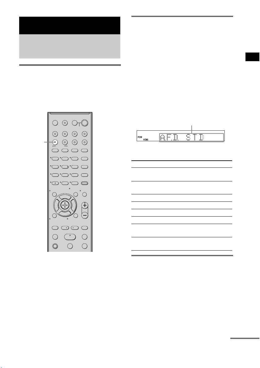
39
ES
Funciones de sonido envolvente
Selección del campo acústico
Este sistema puede crear sonido envolvente
multicanal. Puede seleccionar uno de los campos
acústicos optimizados entre los campos
acústicos preprogramados del sistema.
Cómo escuchar sonido
envolvente mediante el
campo acústico
Pulse SOUND FIELD.
Aparecerá el campo acústico actual.
Cada vez que pulsa el botón SOUND FIELD, la
visualización cambia de manera cíclica como
sigue:
A.F.D. STD t A.F.D. MULTI t
PLII MOVIE t PLII MUSIC t SPORTS t
NEWS t P. AUDIO t OMNI-DIR t
A.F.D. STD t ...
Pulse SOUND FIELD varias veces hasta que
aparezca el campo acústico que desee.
Campos acústicos disponibles
Salida automática del sonido
original
x AUTO FORMAT DIRECT STANDARD
La función de decodificación automática detecta
el tipo de señal de audio de entrada (Dolby
Digital, DTS o estéreo de 2 canales estándar) y
lleva a cabo la decodificación si es necesario.
Este modo presenta el sonido como si estuviera
grabado o codificado, sin añadir efectos
adicionales (como la reverberación).
Funciones de sonido envolvente
Cómo disfrutar del efecto
de sonido envolvente
123
46
78
0
ENTER
9
TV INPUTTHEATER
TV
?/1
AV
?/1
TV BD DVD SAT
TOP MENU MENU
BD/DVD
RETURN/EXIT
TV
REPLAY ADVANCE
F1 F2
AMP MENU
CLEAR
DISPLAY
MUTING
TONE
TUNING - TUNING +
NIGHT
MODE
GUIDE
FAVORITEWIDEPICTUREJUMP
DMPORTTUNER/BANDVIDEO
SOUND FIELD
?/1
TV CH -
PRESET -
TV CH +
PRESET +
F
Gg
f
.
HmM
Xx
<
<
>
5
SYSTEM STANDBY
MENU/HOME
TOOLS/
OPTIONS
TV VOL
MASTER VOL
SOUND
FIELD
Campo acústico Visor
AUTO FORMAT DIRECT
STANDARD
A.F.D. STD
AUTO FORMAT DIRECT
MULTI
A.F.D. MULTI
Dolby Pro Logic II MOVIE PLII MOVIE
Dolby Pro Logic II MUSIC PLII MUSIC
SPORTS SPORTS
NEWS NEWS
PORTABLE AUDIO
ENHANCER
P. AUDIO
OMNI-DIRECTIONAL
SOUND
OMNI-DIR
Área del visor
continúa

40
ES
Sin embargo, si no hay señales de baja
frecuencia (Dolby Digital LFE, etc.), generará
una señal de baja frecuencia para enviarla al
altavoz potenciador de graves.
Emisión de sonido a través de
varios altavoces
x AUTO FORMAT DIRECT MULTI
Este modo permite disfrutar de la reproducción
de sonido de cualquier tipo de disco desde
diferentes altavoces.
• En función de la fuente, puede que el sonido no se
emita desde diferentes altavoces.
• En función del disco o la fuente, es posible que el
principio del sonido se corte, mientras se selecciona
automáticamente el modo óptimo. Para evitar cortes
en el sonido, seleccione “A.F.D. STD”.
Emisión de fuentes de 2
canales como CD a través de
5.1 canales
x Dolby Pro Logic II MOVIE/MUSIC
Dolby Pro Logic II crea cinco canales de salida
de ancho de banda completo a partir de fuentes
de 2 canales. Esto se consigue mediante un
avanzado decodificador de sonido envolvente de
matriz de alta pureza, que extrae las propiedades
espaciales de la grabación original sin añadir
sonidos nuevos ni matices tonales.
• Si la señal de entrada es una fuente multicanal, Dolby
Pro Logic II MOVIE/MUSIC se cancelan y se emite
directamente la fuente multicanal.
• Cuando se recibe sonido de una emisión bilingüe,
Dolby Pro Logic II MOVIE/MUSIC no tienen efecto.
Utilización de los efectos de
sonido
x SPORTS
Este modo genera un sonido realista y detallado,
con efectos de sonido envolvente, como los
aplausos, etc.
x NEWS
Este modo genera una voz nítida del narrador.
x PORTABLE AUDIO ENHANCER
Este modo reproduce una imagen con sonido
mejorado desde un dispositivo de audio portátil.
Se trata de un modo ideal para archivos MP3 y
otros formatos de música comprimidos.
• El PCM lineal multicanal no está disponible para “P.
AUDIO”.
x OMNI-DIRECTIONAL SOUND
Este modo reproduce el efecto estéreo en todo el
entorno, a través de cinco altavoces satélite.
Desactivación del efecto de
sonido envolvente
Pulse SOUND FIELD varias veces hasta que
aparezca “A.F.D. STD” en el visor del panel
superior.
• Los campos acústicos se memorizan para cada entrada
y se guardan incluso si desconecta el cable de
alimentación de ca.
Cuando seleccione una función como “DVD” o
“TUNER”, el campo acústico aplicado por última vez
a la función se aplica automáticamente otra vez. Por
ejemplo, si escucha un DVD con Dolby Pro Logic II
MOVIE como campo acústico y cambia a otra
función y, posteriormente, regresa al DVD, Dolby Pro
Logic II MOVIE se aplicará de nuevo.
Notas
Notas
Nota
Consejo
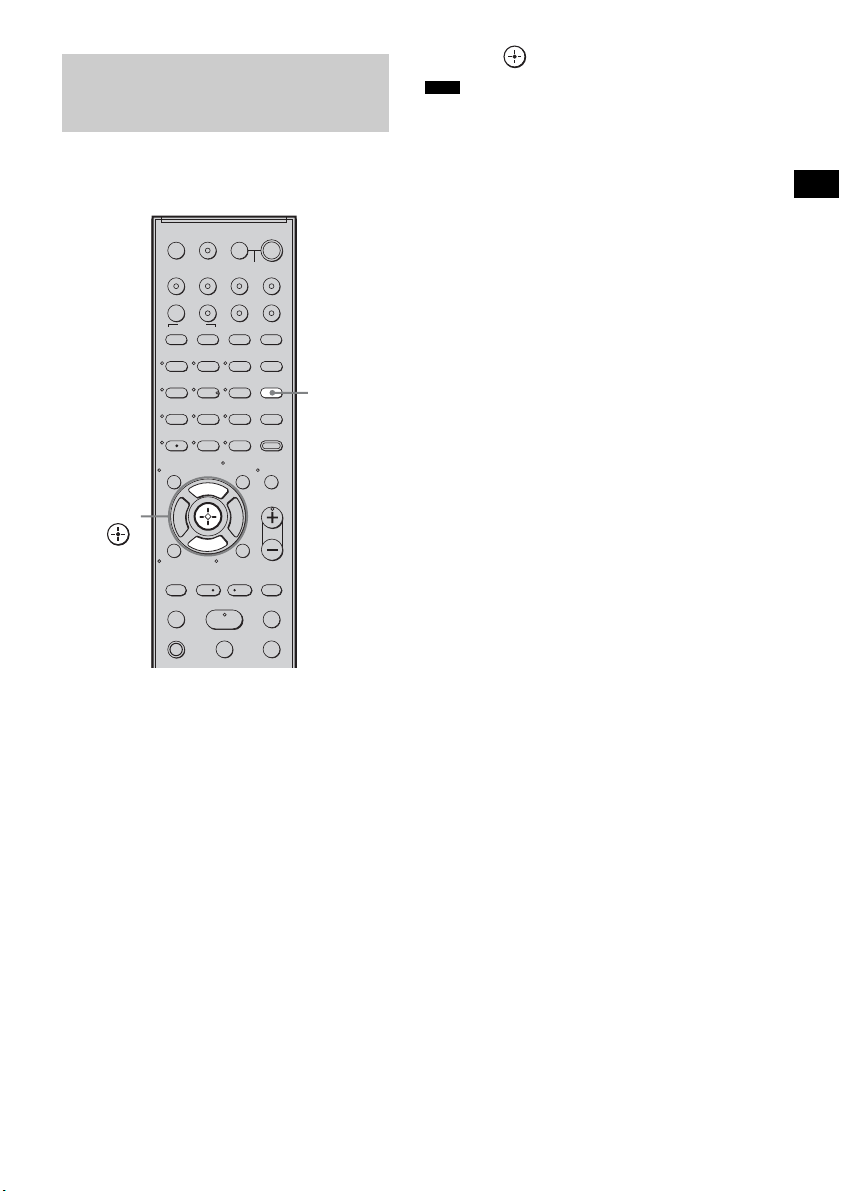
41
ES
Funciones de sonido envolvente
Pulse este botón para ajustar el nivel de graves,
medios y agudos.
1 Pulse TONE varias veces hasta que
aparezca “BASS”, “MIDDLE” o
“TREBLE” en el visor del panel
superior.
• BASS: ajusta el nivel de graves
(entre –6,0 y +6,0 dB, en incrementos de
0,5 dB).
• MIDDLE: ajusta el nivel de medios
(entre –6,0 y +6,0 dB, en incrementos de
0,5 dB).
• TREBLE: ajusta el nivel de agudos
(entre –6,0 y +6,0 dB, en incrementos de
0,5 dB).
2 Pulse X/x para realizar el ajuste.
El valor ajustado aparecerá en el visor del
panel superior.
3 Pulse .
• Si utiliza las funciones S-AIR con los auriculares,
aparece “MIDDLE”. Sin embargo, los auriculares no
disponen de nivel medio.
Ajuste del nivel de graves,
medios y agudos
123
46
78
0
ENTER
9
TV INPUTTHEATER
TV
?/1
AV
?/1
TV BD DVD SAT
TOP MENU MENU
BD/DVD
RETURN/EXIT
TV
REPLAY ADVANCE
F1 F2
AMP MENU
CLEAR
DISPLAY
MUTING
TONE
TUNING - TUNING +
NIGHT
MODE
GUIDE
FAVORITEWIDEPICTUREJUMP
DMPORTTUNER/BANDVIDEO
SOUND FIELD
?/1
TV CH -
PRESET -
TV CH +
PRESET +
F
Gg
f
.
HmM
Xx
<
<
>
5
SYSTEM STANDBY
MENU/HOME
TOOLS/
OPTIONS
TV VOL
MASTER VOL
TONE
X, x,
Nota
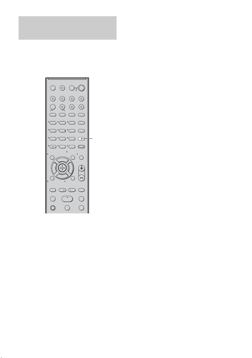
42
ES
Puede disfrutar de los efectos de sonido o de
diálogos de forma similar a como lo haría en un
cine, incluso a un volumen bajo. Esta opción
resulta útil para ver películas de noche.
Pulse NIGHT MODE.
“NIGHT” se encenderá en el visor del panel
superior y el efecto de sonido quedará activado.
Desactivación del efecto de
sonido
Pulse NIGHT MODE de nuevo.
Reproducción de películas
de noche
123
46
78
0
ENTER
9
TV INPUTTHEATER
TV
?/1
AV
?/1
TV BD DVD SAT
TOP MENU MENU
BD/DVD
RETURN/EXIT
TV
REPLAY ADVANCE
F1 F2
AMP MENU
CLEAR
DISPLAY
MUTING
TONE
TUNING - TUNING +
NIGHT
MODE
GUIDE
FAVORITEWIDEPICTUREJUMP
DMPORTTUNER/BANDVIDEO
SOUND FIELD
?/1
TV CH -
PRESET -
TV CH +
PRESET +
F
Gg
f
.
HmM
Xx
<
<
>
5
SYSTEM STANDBY
MENU/HOME
TOOLS/
OPTIONS
TV VOL
MASTER VOL
NIGHT
MODE

43
ES
Funciones de “BRAVIA” Sync
Si conecta componentes de Sony compatibles
con “BRAVIA” Sync con un cable HDMI (no
suministrado), el funcionamiento se simplifica
de la forma siguiente:
• Reproducción mediante una pulsación: al
reproducir un componente como un reproductor
de Blu-ray Disc/DVD (grabadora), el sistema y
el televisor se encienden automáticamente y
cambian a la entrada HDMI correspondiente.
• Control de audio del sistema: al ver el televisor,
puede seleccionar que el sonido se emita del
altavoz del televisor o de los altavoces del
sistema.
• Apagado del sistema: al apagar el televisor, el
sistema y los componentes conectados también
se apagan a la vez.
“BRAVIA” Sync es compatible con un televisor
Sony, un reproductor Blu-ray Disc/DVD o un
amplificador AV con la función Control por
HDMI.
La función Control por HDMI es una función de
control mutuo estándar utilizada por CEC
(Consumer Electronics Control) para HDMI
(High-Definition Multimedia Interface).
La función Control por HDMI no
funcionará en los casos
siguientes:
• Si conecta este sistema a un componente que
no se ajuste a la función Control por HDMI.
• Si conecta el sistema y los componentes con
una conexión que no sea HDMI.
Sony recomienda conectar el sistema a productos
que incorporen “BRAVIA” Sync.
• En función del componente conectado, puede que la
función Control por HDMI no funcione. Para obtener
más información, consulte el manual de instrucciones
del componente.
Para utilizar “BRAVIA” Sync, active la función
Control por HDMI del sistema y el componente
conectado.
Al conectar un televisor Sony con la función
Control por HDMI, la función Control por
HDMI del sistema y el componente conectado
pueden ajustarse a la vez seleccionando la
función Control por HDMI del televisor.
1 Asegúrese de que el sistema está
conectado al televisor y los
componentes conectados (que deben
ser compatibles con la función Control
por HDMI) mediante cables HDMI (no
suministrado).
2 Encienda el sistema, el televisor y los
componentes conectados.
Funciones de “BRAVIA” Sync
¿Qué es “BRAVIA” Sync?
Nota
Preparativos para utilizar
“BRAVIA” Sync
123
46
78
0
ENTER
9
TV INPUTTHEATER
TV
?/1
AV
?/1
TV BD DVD SAT
TOP MENU MENU
BD/DVD
RETURN/EXIT
TV
REPLAY ADVANCE
F1 F2
AMP MENU
CLEAR
DISPLAY
MUTING
TONE
TUNING - TUNING +
NIGHT
MODE
GUIDE
FAVORITEWIDEPICTUREJUMP
DMPORTTUNER/BANDVIDEO
SOUND FIELD
?/1
TV CH -
PRESET -
TV CH +
PRESET +
F
Gg
f
.
HmM
Xx
<
<
>
5
SYSTEM STANDBY
MENU/HOME
TOOLS/
OPTIONS
TV VOL
MASTER VOL
?/1
AMP
MENU
Botones de
entrada
C, X, x, c,
continúa

44
ES
3 Seleccione la entrada del sistema
conectado al componente que desea
reproducir (BD, DVD, SAT) y cambie la
entrada HDMI del televisor de modo
que aparezca la imagen del
componente conectado.
4 Active la función Control por HDMI del
televisor.
La función Control por HDMI del sistema y
el componente conectado se activan a la vez.
Durante el ajuste, aparece “SCANNING”
en el visor del panel superior. Después del
ajuste, aparece “COMPLETE” en el visor
del panel superior. Espere a que termine el
ajuste.
Si no aparece ni “SCANNING” ni
“COMPLETE” tras realizar los
pasos anteriores
Active por separado la función Control por
HDMI del sistema y del componente conectado.
1 Pulse AMP MENU.
2 Pulse x/X varias veces hasta que
aparezca “SET HDMI” y, a
continuación, pulse o c.
3 Pulse x/X varias veces hasta que
aparezca “CTRL: HDMI” y, a
continuación, pulse o c.
4 Pulse x/X para seleccionar “CTRL ON”
y, a continuación, pulse o c.
5 Pulse AMP MENU.
El menú AMP se desactivará. La función
Control por HDMI quedará activada.
6 Active la función Control por HDMI del
componente conectado.
Para obtener más información, consulte el
manual de instrucciones del componente
conectado.
7 Seleccione la entrada del sistema
conectado al componente para el que
desea utilizar la función Control por
HDMI (BD, DVD, SAT) y repita el paso 6.
Si añade o vuelve a conectar el
componente
Siga los pasos descritos en “Preparativos para
utilizar “BRAVIA” Sync” y “Si no aparece ni
“SCANNING” ni “COMPLETE” tras realizar
los pasos anteriores”.
• Durante el ajuste de la función Control por HDMI
para el sistema, la función Control de audio del
sistema no funcionará.
• Si no puede ajustarse a la vez la función Control por
HDMI del componente conectado ajustando la
función “Control por HDMI” del televisor, ajuste la
función Control por HDMI con el menú del
componente conectado.
• Para obtener más información sobre cómo ajustar el
televisor y los componentes conectados, consulte los
manuales de instrucciones correspondientes.
• El ajuste predeterminado de la función Control por
HDMI del sistema es “OFF”.
Notas
Consejo
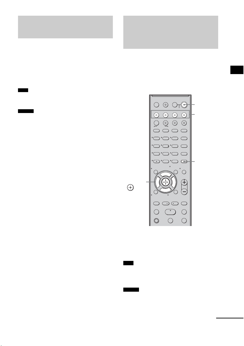
45
ES
Funciones de “BRAVIA” Sync
Reproduzca un componente conectado.
El sistema y el televisor se encienden
automáticamente y cambian a la entrada HDMI
correspondiente.
• En función del televisor, es posible que no se emita el
principio del contenido.
• Puede utilizar el reproductor (grabadora) Blu-ray
Disc/DVD conectado al sistema, incluso si desactiva
el sistema. El indicador POWER / ACTIVE
STANDBY se encenderá de color naranja en esta
ocasión.
Puede escuchar el sonido del televisor desde los
altavoces del sistema mediante una sencilla
operación. Para obtener más información,
consulte el manual de instrucciones del televisor.
Pulse ?/1 para encender el sistema.
El sonido se emite a través de los altavoces del
sistema. Al apagar el sistema, el sonido se emite
desde el altavoz del televisor.
• Si enciende el televisor antes de que se encienda el
sistema, el sonido del televisor se emitirá
transcurridos unos segundos.
• Puede ajustar el volumen y apagar el sonido del
sistema mediante el mando a distancia del televisor.
Utilización de Blu-ray
Disc/DVD
(Reproducción mediante una
pulsación)
Nota
Consejo
Cómo escuchar el sonido
del televisor desde los
altavoces
(Control de audio del sistema)
Nota
Consejo
123
46
78
0
ENTER
9
TV INPUTTHEATER
TV
?/1
AV
?/1
TV BD DVD SAT
TOP MENU MENU
BD/DVD
RETURN/EXIT
TV
REPLAY ADVANCE
F1 F2
AMP MENU
CLEAR
DISPLAY
MUTING
TONE
TUNING - TUNING +
NIGHT
MODE
GUIDE
FAVORITEWIDEPICTUREJUMP
DMPORTTUNER/BANDVIDEO
SOUND FIELD
?/1
TV CH -
PRESET -
TV CH +
PRESET +
F
Gg
f
.
HmM
Xx
<
<
>
5
SYSTEM STANDBY
MENU/HOME
TOOLS/
OPTIONS
TV VOL
MASTER VOL
?/1
AMP
MENU
Botones de
entrada
C, X, x, c,
continúa

46
ES
Uso de la función de límite de
volumen
Si la función Control de audio del sistema está
activada y el método de emisión cambia del
altavoz del televisor al altavoz del sistema
automáticamente, puede que el sonido emitido
sea alto, en función del nivel de volumen del
sistema. Para evitarlo, puede limitar el nivel de
volumen máximo.
1 Pulse AMP MENU.
2 Pulse x/X varias veces hasta que
aparezca “SET HDMI” y, a
continuación, pulse o c.
3 Pulse x/X varias veces hasta que
aparezca “VOL LIMIT” y, a
continuación, pulse o c.
4 Pulse x/X para seleccionar el nivel de
volumen máximo que desee.
El nivel de volumen máximo cambia de la
forma siguiente:
5 Pulse AMP MENU.
El menú AMP se desactivará.
• Esta función esta disponible solo si la función Control
por HDMI está activada.
• La función no estará disponible si el método de
emisión cambia del altavoz del sistema al altavoz del
televisor.
• Sony recomienda ajustar el nivel de volumen máximo
algo por debajo del volumen que normalmente
seleccione.
• Independientemente del nivel de volumen máximo
que seleccione, el botón VOLUME +/– del altavoz
potenciador de graves y el botón MASTER VOL +/–
del mando a distancia pueden utilizarse igualmente.
• Si no desea limitar el nivel de volumen máximo,
seleccione “MAX”.
Utilización de los botones de
entrada del mando a distancia
Los botones de entrada (TV (blanco), BD, DVD,
SAT, VIDEO, DMPORT) funcionan del modo
siguiente si la función Control por HDMI está
activada.
• BD, DVD, SAT, VIDEO, DMPORT: como la
entrada del televisor también se cambia
automáticamente, puede ver la imagen del
componente seleccionado en el televisor solo
pulsando los botones.
• TV: la entrada del televisor cambia
automáticamente. Al conectar un televisor
Sony, puede ver el televisor simplemente
pulsando el botón.
• Puede controlar los componentes de Sony conectados
pulsando los botones de entrada. Para obtener más
información, consulte “Control de los componentes
Sony conectados con el mando a distancia”
(página 52).
Notas
Consejos
MAX y 49 y 48 y
...... y 2 y 1 y MIN
Consejo
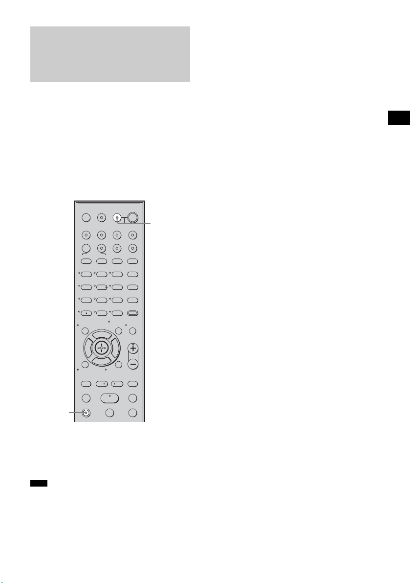
47
ES
Funciones de “BRAVIA” Sync
Si desactiva el televisor con el botón de
encendido del mando a distancia del televisor, el
sistema y los componentes conectados se
desactivan automáticamente.
Asimismo, si desactiva el televisor con el mando
a distancia del sistema, el sistema y los
componentes conectados se desactivan
automáticamente.
Mantenga pulsado el botón TV (naranja) y
pulse AV ?/1.
El televisor, el sistema y los componentes
conectados se desactivarán.
• En función del estado, los componentes conectados
puede que no se desactiven. Para obtener más
información, consulte los manuales de instrucciones
de los componentes conectados.
Desactivación del
televisor, el sistema y los
componentes conectados
(Apagado del sistema)
Nota
123
46
78
0
ENTER
9
TV INPUTTHEATER
TV
?/1
AV
?/1
TV BD DVD SAT
TOP MENU MENU
BD/DVD
RETURN/EXIT
TV
REPLAY ADVANCE
F1 F2
AMP MENU
CLEAR
DISPLAY
MUTING
TONE
TUNING - TUNING +
NIGHT
MODE
GUIDE
FAVORITEWIDEPICTUREJUMP
DMPORTTUNER/BANDVIDEO
SOUND FIELD
?/1
TV CH -
PRESET -
TV CH +
PRESET +
F
Gg
f
.
HmM
Xx
<
<
>
5
SYSTEM STANDBY
MENU/HOME
TOOLS/
OPTIONS
TV VOL
MASTER VOL
AV ?/1
TV
(naranja)
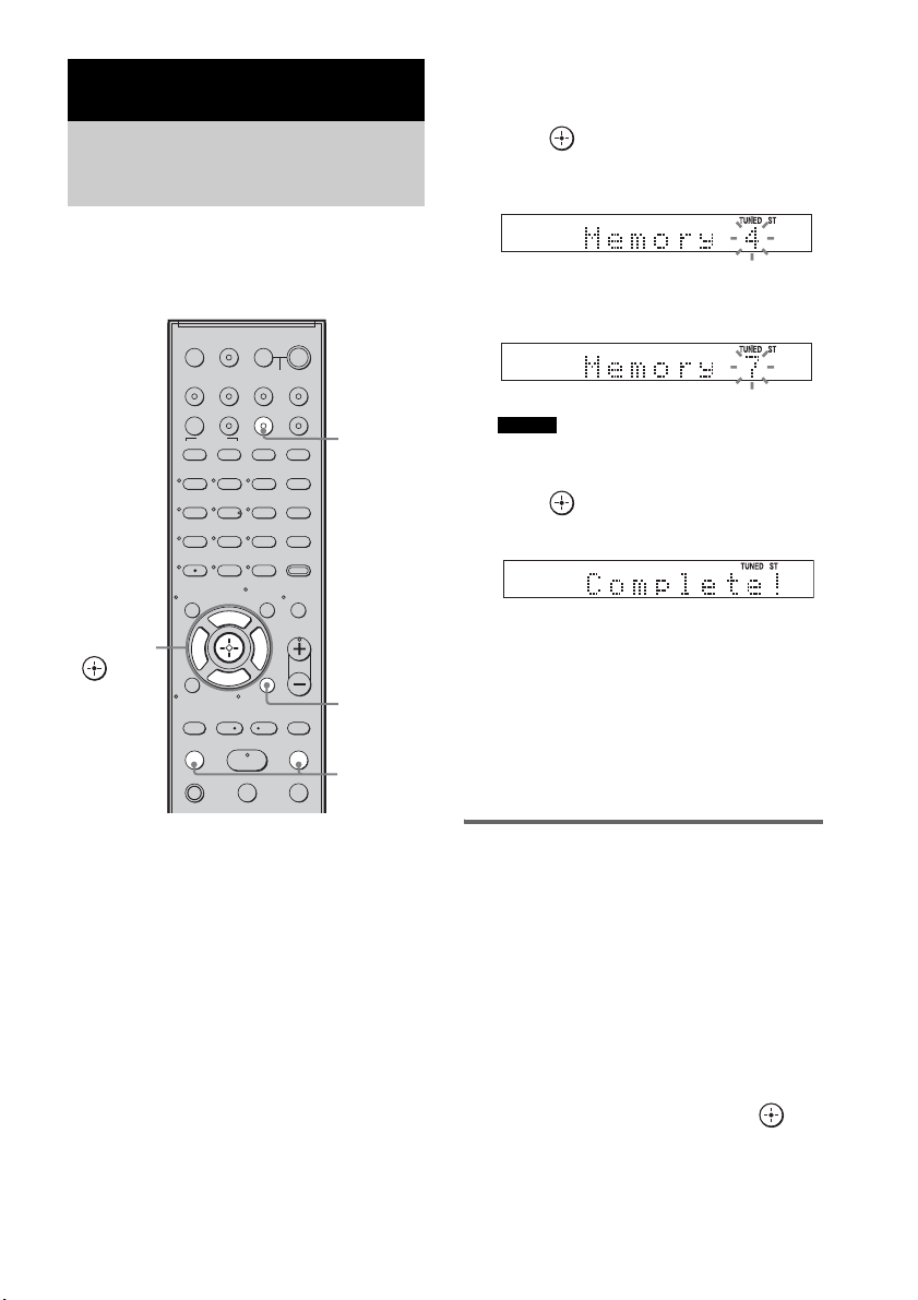
48
ES
Puede memorizar 20 emisoras de FM y 10
emisoras de AM. Antes de la sintonización,
asegúrese de bajar el volumen al mínimo.
1 Pulse TUNER/BAND.
Puede cambiar entre “FM” o “AM”
pulsando TUNER/BAND.
2 Mantenga pulsado TUNING + o – hasta
que empiece la exploración
automática.
La exploración se detiene cuando el sistema
sintoniza una emisora. “TUNED” y “ST”
(para programas estéreo) aparecerán en el
visor del panel superior.
3 Pulse MENU.
4 Pulse X/x varias veces hasta que
aparezca “Memory?” en el visor del
panel superior.
5 Pulse .
El visor del panel superior muestra un
número de memorización.
6 Pulse X/x para seleccionar el número
de memorización que desee.
• Puede seleccionar el número de memorización
directamente pulsando los botones numéricos.
7 Pulse .
La emisora se almacenará.
8 Pulse MENU.
9 Repita los pasos 2 a 8 para almacenar
más emisoras.
Para cambiar el número de
memorización
Vuelva a comenzar desde el paso 3.
Cambio del intervalo de
sintonización de AM
Es posible ajustar el intervalo de sintonización
de AM en 10 kHz o 9 kHz.
1 Pulse TUNER/BAND varias veces hasta
que “AM” aparezca en el visor del panel
frontal.
2 Pulse MENU.
3 Pulse X/x varias veces hasta que “AM
Step?” aparezca en el visor del panel
frontal y, a continuación, pulse o
c.
Aparecerá “9k t 10k” o “10k t 9k” en el
visor del panel frontal.
Funciones del sintonizador
Memorización de
emisoras de radio
123
46
78
0
ENTER
9
TV INPUTTHEATER
TV
?/1
AV
?/1
TV BD DVD SAT
TOP MENU MENU
BD/DVD
RETURN/EXIT
TV
REPLAY ADVANCE
F1 F2
AMP MENU
CLEAR
DISPLAY
MUTING
TONE
TUNING - TUNING +
NIGHT
MODE
GUIDE
FAVORITEWIDEPICTUREJUMP
DMPORTTUNER/BANDVIDEO
SOUND FIELD
?/1
TV CH -
PRESET -
TV CH +
PRESET +
F
Gg
f
.
HmM
Xx
<
<
>
5
SYSTEM STANDBY
MENU/HOME
TOOLS/
OPTIONS
TV VOL
MASTER VOL
C, X, x, c,
TUNING
–/+
TUNER/
BAND
MENU
Consejo
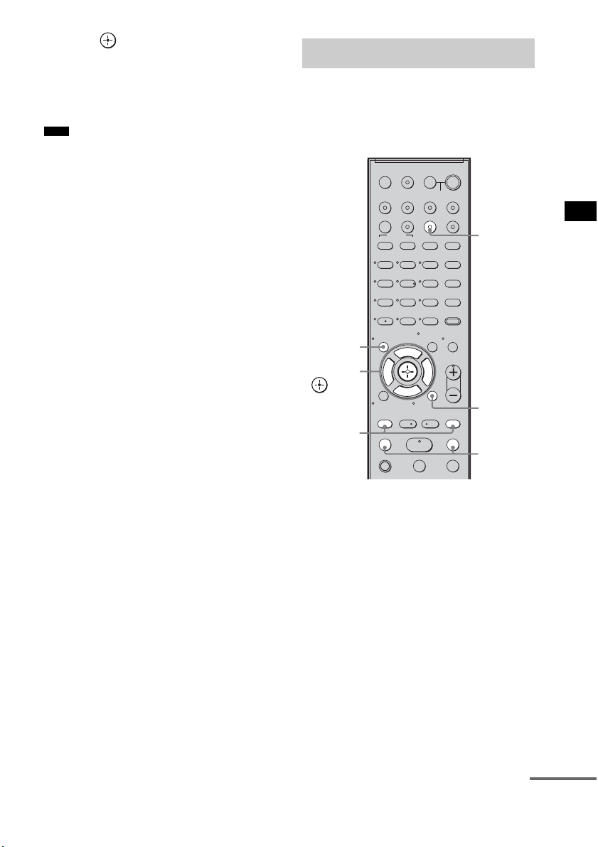
49
ES
Funciones del sintonizador
4 Pulse .
“Complete!” aparecerá en el visor del panel
frontal. El intervalo de sintonización de AM
ha cambiado.
5 Pulse MENU.
• Si cambia el intervalo, se borrarán las emisoras
memorizadas de AM.
En primer lugar, memorice emisoras de radio en
la memoria del sistema (consulte
“Memorización de emisoras de radio”
(página 48)).
1 Pulse TUNER/BAND.
Se sintonizará la última emisora encontrada.
Puede cambiar entre “FM” o “AM”
pulsando TUNER/BAND.
2 Pulse PRESET + o – varias veces para
seleccionar la emisora memorizada.
Cada vez que pulse el botón, el sistema
sintonizará una emisora memorizada.
Puede seleccionar el número de
memorización directamente pulsando los
botones numéricos.
3 Ajuste el volumen del sistema.
Para apagar la radio
Pulse "/1 para desactivar el sistema o para
cambiar a otra función.
Nota
Cómo escuchar la radio
123
46
78
0
ENTER
9
TV INPUTTHEATER
TV
?/1
AV
?/1
TV BD DVD SAT
TOP MENU MENU
BD/DVD
RETURN/EXIT
TV
REPLAY ADVANCE
F1 F2
AMP MENU
CLEAR
DISPLAY
MUTING
TONE
TUNING - TUNING +
NIGHT
MODE
GUIDE
FAVORITEWIDEPICTUREJUMP
DMPORTTUNER/BANDVIDEO
SOUND FIELD
?/1
TV CH -
PRESET -
TV CH +
PRESET +
F
Gg
f
.
HmM
Xx
<
<
>
5
SYSTEM STANDBY
MENU/HOME
TOOLS/
OPTIONS
TV VOL
MASTER VOL
C, X, x, c,
TUNING
–/+
TUNER/
BAND
MENU
PRESET
–/+
DISPLAY
continúa
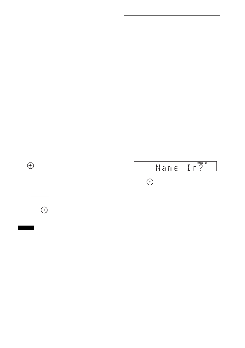
50
ES
Para escuchar emisoras no
memorizadas
Utilice la sintonización manual o automática en
el paso 2.
Para la sintonización manual, pulse TUNING +
o – varias veces.
Para la sintonización automática, mantenga
pulsado TUNING + o –. La sintonización
automática se detiene de forma automática
cuando el sistema encuentra una emisora de
radio. Para detener la sintonización automática
manualmente, pulse TUNING + o –.
Si el sonido de un programa de FM
no es claro
Si el sonido de un programa de FM no es claro,
puede seleccionar la recepción monoaural. La
recepción será de mejor calidad, aunque se
perderá el efecto estéreo.
1 Pulse MENU.
2 Pulse X/x varias veces hasta que
aparezca “FM Mode?” en el visor del
panel superior y, a continuación, pulse
o c.
3 Pulse X/x para seleccionar “MONO”.
El valor predeterminado aparecerá
subrayado.
•STEREO
: recepción estéreo.
• MONO: recepción monoaural.
4 Pulse .
5 Pulse MENU.
• Para mejorar la recepción, cambie la orientación de
las antenas suministradas.
Asignación de un nombre a
emisoras memorizadas
Puede introducir un nombre para las emisoras
memorizadas. Estos nombres (por ejemplo,
“XYZ”) aparecerán en el visor del panel superior
al seleccionar la emisora.
Tenga en cuenta que solo puede introducir un
nombre para cada emisora memorizada.
1 Pulse TUNER/BAND.
Se sintonizará la última emisora encontrada.
Puede cambiar entre “FM” o “AM”
pulsando TUNER/BAND.
2 Pulse PRESET + o – varias veces para
seleccionar la emisora memorizada
para la que desee crear un nombre de
índice.
3 Pulse MENU.
4 Pulse X/x varias veces hasta que
aparezca “Name In?” en el visor del
panel superior.
5 Pulse .
6 Cree un nombre con C/X/x/c.
Pulse X/x para seleccionar un carácter y
pulse c para desplazar el cursor a la
posición siguiente.
Para componer el nombre de una emisora de
radio, puede utilizar letras, números y otros
símbolos.
Si comete un error
Pulse C/c varias veces hasta que parpadee
el carácter que desea cambiar y, a
continuación, pulse X/x para seleccionar el
carácter deseado.
Para borrar el carácter, pulse C/c varias
veces hasta que el carácter que desea borrar
parpadee y, a continuación, pulse CLEAR.
Consejo

51
ES
Funciones del sintonizador
7 Pulse .
“Complete!” aparecerá en el visor del panel
superior y se guardará el nombre de la
emisora.
8 Pulse MENU.
• Para comprobar la frecuencia en el visor del panel
superior, pulse DISPLAY varias veces (página 51).
Visualización del nombre de la
emisora o la frecuencia en el
visor del panel superior
Si se ajusta el sistema en “FM” o “AM”, puede
comprobar la frecuencia en el visor del panel
superior.
Pulse DISPLAY.
Cada vez que pulse DISPLAY, el visor del panel
superior cambiará de la siguiente manera.
1 Nombre de la emisora*
2 Frecuencia**
* Ésta se muestra si ha introducido el nombre de una
emisora memorizada.
** Regresa a la pantalla original transcurridos varios
segundos.
Consejo
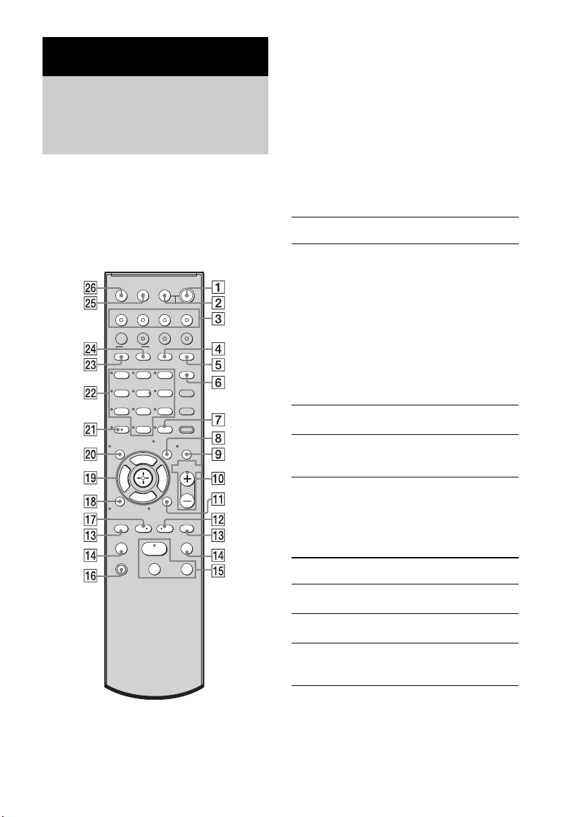
52
ES
El mando a distancia de este sistema le permite
controlar los componentes Sony que tenga
conectados.
Según el componente, es posible que no pueda
seleccionar alguna de las funciones. En ese caso,
selecciónelas mediante el mando a distancia del
componente.
* Los botones 5, H y MASTER VOL + disponen de
un punto táctil. Utilice los puntos táctiles como guía
durante el uso del mando a distancia.
Para controlar el componente
1 Para seleccionar el componente que
desea controlar, pulse uno de los
botones de entrada
3 (TV, BD, DVD o
SAT).
Se activa el componente asignado al botón
de entrada seleccionado.
2 Consulte la siguiente tabla y pulse el
botón que se corresponda con la
función deseada.
Operaciones más frecuentes
Para controlar el televisor
Para controlar el televisor, mantenga pulsado el
botón TV
qh (naranja) pulsando los botones con
un punto naranja o con letra naranja.
Ajustes avanzados
Control de los componentes
Sony conectados con el
mando a distancia
123
46
78
0
ENTER
9
TV INPUTTHEATER
TV
?/1
AV
?/1
TV BD DVD SAT
TOP MENU MENU
BD/DVD
RETURN/EXIT
TV
REPLAY ADVANCE
F1 F2
AMP MENU
CLEAR
DISPLAY
MUTING
TONE
TUNING - TUNING +
NIGHT
MODE
GUIDE
FAVORITEWIDEPICTUREJUMP
DMPORTTUNER/BANDVIDEO
SOUND FIELD
?/1
TV CH -
PRESET -
TV CH +
PRESET +
F
Gg
f
.
HmM
Xx
<
<
>
5
SYSTEM STANDBY
MENU/HOME
TOOLS/
OPTIONS
TV VOL
MASTER VOL
Botón del mando a
distancia
Función
2 TV ?/1
AV ?/1
(encendido/espera)
Permite encender o apagar
el televisor o los
componentes de audio/vídeo
Sony asignados al mando a
distancia.
Para apagar el sistema y
todos los componentes
asignados al mando a
distancia (SYSTEM
STANDBY), pulse
1
?/1 y 2 TV ?/1/
AV
?/1 al mismo tiempo.
7 ENTER Permite introducir la
selección.
ws Botones numéricos Permite seleccionar
canales y pistas
directamente.
Botón del mando a
distancia
Función
4 WIDE Ajusta el modo
panorámico.
5 FAVORITE Muestra la lista de canales
favoritos almacenados.
6 GUIDE Muestra la guía cuando
está viendo canales
analógicos o digitales.
53
ES
Ajustes avanzados
Para controlar la grabadora de
DVD/grabadora de Blu-ray Disc
8 TOOLS/
OPTIONS
Permite acceder a distintas
opciones de visualización
y cambiar/realizar ajustes
en función del formato de
la fuente y la pantalla.
9 MUTING Permite desactivar el
sonido.
q; TV VOL +/– Sirve para ajustar el
volumen.
qa MENU/HOME Permite seleccionar
canales o fuentes de
entrada y modificar los
ajustes del televisor.
qd TV CH +/– Selecciona el canal
siguiente (+) o anterior (–).
Para desplazarse
rápidamente por los
canales, mantenga pulsado
uno de los botones +/–.
qk RETURN/EXIT Permite volver a la última
pantalla de cualquier menú
que se haya mostrado.
ql C, X, x, c, Selecciona un elemento de
menú e introduce la
selección.
w; DISPLAY Muestra el número de
canal actual, etc.
wa Selecciona canales
digitales mediante los
botones 0-9 y ENTER. Por
ejemplo, para introducir
“2.1”, pulse , ,
y ENTER.
ws Botones numéricos Permite seleccionar los
canales. Para cambiar
canales de forma
inmediata, pulse 7
ENTER.
wd JUMP Alterna entre dos canales.
El televisor alterna entre el
canal actual y el último
canal seleccionado.
wf PICTURE Muestra el modo de
imagen disponible.
wg TV INPUT Selecciona la entrada.
Botón del mando a
distancia
Función
2
1
wh THEATER Permite establecer
automáticamente los
ajustes óptimos de imagen
para ver películas si tiene
conectado un televisor
Sony compatible con el
botón THEATER.
Asimismo, cuando se
conecta el televisor y el
sistema con conexión
HDMI, el sonido cambia
automáticamente a la
salida de audio de este
sistema y se activa la
función Control por
HDMI.
Botón del mando a
distancia
Función
4 F1 Selecciona el HDD.
5 F2 Selecciona el Blu-ray Disc/
DVD.
qa MENU/HOME Muestra el MENU.
qs •
, Permite avanzar durante la
visualización de
programas grabados.
qd . Avanza y retrocede los
capítulos.
> Permite avanzar al
siguiente capítulo
disponible.
qf m/M Permite el retroceso o el
avance rápido del disco si
se pulsa durante la
reproducción.
qg H (reproducción)/
X (pausa, púlselo de
nuevo para reanudar
la reproducción
normal)/x (parada)
Botones del modo de
reproducción.
qj
< • Permite retroceder
mientras se visualizan
programas grabados o en
directo.
Botón del mando a
distancia
Función
continúa
54
ES
Para controlar el reproductor de
DVD/reproductor de Blu-ray Disc
Para controlar el HDD/DVD
COMBO
Para controlar el SAT
• Las explicaciones anteriores se muestran a modo de
ejemplo. En función del componente, tal vez no sea
posible realizar todo lo descrito anteriormente o bien
se pueda realizar de forma distinta a la descrita.
ql C, X, x, c, Selecciona un elemento de
menú e introduce la
selección.
wd BD/DVD
TOP MENU
Muestra el menú principal/
menú de disco.
wf BD/DVD MENU
Botón del mando a
distancia
Función
qa MENU/HOME Muestra el MENU.
qs •
, Avance.
qd ./> Avanza y retrocede los
capítulos.
qf m/M Permite el retroceso o el
avance rápido del disco si
se pulsa durante la
reproducción.
qg H (reproducción)/
X (pausa, púlselo de
nuevo para reanudar
la reproducción
normal)/x (parada)
Botones del modo de
reproducción.
qj
< •Retroceso.
ql C, X, x, c, Selecciona un elemento de
menú e introduce la
selección.
wd BD/DVD
TOP MENU
Muestra el menú principal/
menú de disco.
wf BD/DVD MENU
Botón del mando a
distancia
Función
4 F1 Selecciona el HDD.
5 F2 Selecciona el DVD.
qa MENU/HOME Muestra el MENU.
qs •
, Permite avanzar.
qd ./> Permite especificar el
capítulo o pista anterior o
siguiente.
Botón del mando a
distancia
Función
qf m/M Permite el retroceso o el
avance rápido del disco si
se pulsa durante la
reproducción.
qg H (reproducción)/
X (pausa, púlselo de
nuevo para reanudar
la reproducción
normal)/x (parada)
Botones del modo de
reproducción.
qj
< • Permite cambiar al modo
de repetición.
ql C, X, x, c, Permite desplazar el
resaltado (cursor) y
selecciona el elemento.
wd BD/DVD
TOP MENU
Muestra el menú principal/
menú de disco.
wf BD/DVD MENU
Botón del mando a
distancia
Función
6 GUIDE Muestra el menú de guía.
qa MENU/HOME Muestra el MENU.
ql C, X, x, c, Selecciona un elemento de
menú e introduce la
selección.
Nota
Botón del mando a
distancia
Función
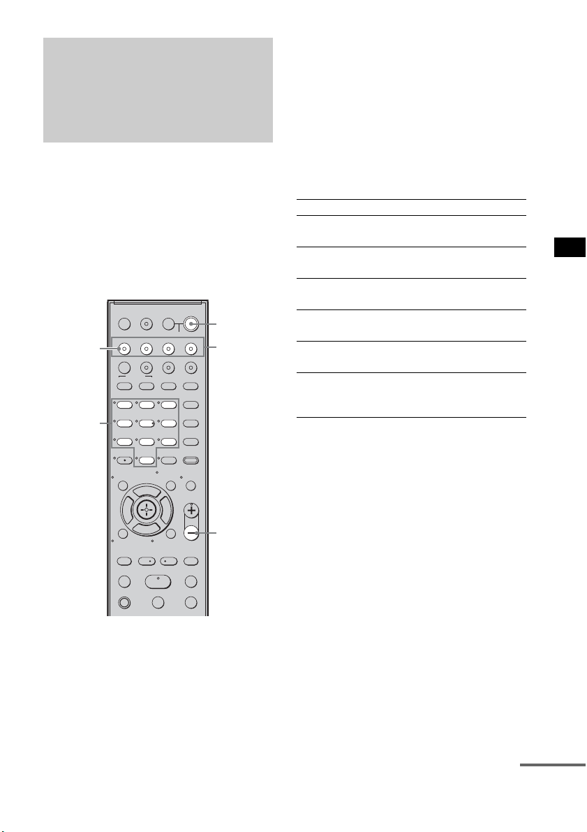
55
ES
Ajustes avanzados
Puede modificar los ajustes de fábrica de los
botones de entrada en función de los
componentes de su sistema.
Por ejemplo, si conecta un reproductor de Blu-
ray Disc a la toma de DVD del sistema, puede
asignar el botón DVD del mando a distancia para
que controle el reproductor de Blu-ray Disc.
Sin embargo, el botón TV (blanco) del mando a
distancia solo puede asignarse al televisor.
1 Mantenga pulsado el botón de entrada
cuya asignación desee cambiar.
Ejemplo: Mantenga pulsado DVD.
2 Consulte la siguiente tabla y pulse el
botón que se corresponda con la
categoría deseada.
Ejemplo: Pulse 3.
A partir de este momento, podrá utilizar el
botón DVD para controlar el reproductor de
Blu-ray Disc.
Categorías y botones
correspondientes a BD, DVD y
SAT
* Éste es el ajuste predeterminado del botón DVD.
Las grabadoras de DVD Sony se controlan con un
ajuste DVD1 o DVD3. Si desea más información,
consulte el manual de instrucciones de la grabadora
de DVD.
** Éste es el ajuste predeterminado del botón BD.
Si desea más información sobre el ajuste BD1 o
BD3, consulte el manual de instrucciones del
reproductor o la grabadora de Blu-ray Disc.
*** Éste es el ajuste predeterminado del botón SAT.
Modificación de las
asignaciones de los
botones de entrada del
mando a distancia
123
46
78
0
ENTER
9
TV INPUTTHEATER
TV
?/1
AV
?/1
TV BD DVD SAT
TOP MENU MENU
BD/DVD
RETURN/EXIT
TV
REPLAY ADVANCE
F1 F2
AMP MENU
CLEAR
DISPLAY
MUTING
TONE
TUNING - TUNING +
NIGHT
MODE
GUIDE
FAVORITEWIDEPICTUREJUMP
DMPORTTUNER/BANDVIDEO
SOUND FIELD
?/1
TV CH -
PRESET -
TV CH +
PRESET +
F
Gg
f
.
HmM
Xx
<
<
>
5
SYSTEM STANDBY
MENU/HOME
TOOLS/
OPTIONS
TV VOL
MASTER VOL
MASTER
VOL –
Botones
numéricos
Botones
de entrada
?/1
TV
(blanco)
Categorías Pulse
Reproductor de DVD
(modo de comando DVD1)*
1
Grabadora de DVD
(modo de comando DVD3)
2
Reproductor de Blu-ray Disc
(modo de comando BD1)**
3
Grabadora de Blu-ray Disc
(modo de comando BD3)
4
Grabadora de vídeo digital
(Terminal CATV digital)
7
DSS
(Receptor de emisiones vía satélite
digital)***
8
continúa

56
ES
Categorías y botones
correspondientes para televisor
* Éste es el ajuste predeterminado del botón TV
(blanco).
Cuando este ajuste está seleccionado, se cambia la
entrada de audio del televisor y la imagen del
sintonizador del televisor se muestra en la pantalla
del televisor automáticamente al pulsar el botón
TV (blanco).
** Cuando se selecciona este ajuste, se cambia
automáticamente a la entrada de audio del televisor
al pulsar el botón TV (blanco).
Para borrar todas las
asignaciones de los botones del
mando a distancia
Mantenga pulsado MASTER VOL –, ?/1, y
luego pulse TV INPUT. La configuración del
mando a distancia vuelve a los ajustes de fábrica.
Utilización del menú AMP
Es posible ajustar los siguientes elementos con
AMP MENU en el mando a distancia.
Los valores predeterminados aparecerán
subrayados.
Categorías Pulse
TV* 5
TV** 6
Configuración y ajustes
mediante el menú del
amplificador
CTRL ON
CTRL OFF
CTRL: HDMI
MAX, 49,
48…..2, 1,
MIN
VOL LIMIT
2)
SET
HDMI
1)
FL 10’ 0”*
(3 m 0 cm)
FL DIST
CENTER YES
CENTER NO
CENTER SPSP
SETUP
SUR YES
SUR NO
SUR SP
CNT 10’ 0”*
(3 m 0 cm)
CNT DIST
FR 10’ 0”*
(3 m 0 cm)
FR DIST
SR 10’ 0”*
(3 m 0 cm)
SR DIST
SL 10’ 0”*
(3 m 0 cm)
SL DIST
SW 10’ 0”*
(3 m 0 cm)
SW DIST
A. CAL START
YES
NO
A. CAL CLEAR
A. CAL
MENU
3)
* Para los modelos de Norteamérica
57
ES
Ajustes avanzados
1)
Consulte “Funciones de “BRAVIA” Sync”
(página 43).
2)
Este ajuste solo aparece cuando “CTRL: HDMI”
está en estado “CTRL ON”.
3)
Consulte “Paso 6: calibración de los ajustes
adecuados de forma automática” (página 24). El
ajuste “A. CAL CLEAR” solo aparece cuando se
guarda el resultado de la autocalibración.
4)
Este ajuste es solo para las señales de entrada óptica
y coaxial.
5)
Este ajuste solo aparece cuando se inserta el
transmisor S-AIR (no suministrado).
1 Pulse AMP MENU para acceder al menú
AMP.
2 Pulse C/X/x/c varias veces para
seleccionar el elemento y el ajuste.
3 Pulse AMP MENU para salir del menú
AMP.
En las siguientes páginas se incluye información
detallada de cada ajuste.
FL 0.0
FL LEVEL
T. TONE ON
T. TONE OFF
TEST TONELEVEL
CNT 0.0
CNT LEVEL
FR 0.0FR LEVEL
SR 0.0
SR LEVEL
SL 0.0SL LEVEL
SW 0.0
SW LEVEL
ANALOG VD
ANALOG TV
A. ASSIGN
AUDIO
ANALOG SAT
ANALOG DVD
ANALOG BD
COAX SAT
COAX DVD
D. ASSIGN
MAIN
SUB
DUAL MONO
MAIN+SUB
CUST-
OMIZE
SYNC OFF,
1, 2, …..20
A/V SYNC
4)
DRC MAX
DRC STD
AUDIO DRC
DRC OFF
SLEEP OFF, 10M,
20M, …..90M
SLEEP
DIMMER ON
DIMMER OFF
DIMMER
DSPL ON
DSPL OFF
DISPLAY
START
CONDITION
PAIRING
S-AIR
SET
5)
S-AIR ID: A
S-AIR ID: B
S-AIR ID
S-AIR ID:
C
PARTY
SEPARATE
S-AIR MODE
AUTO
ON
RF CHANGE
OFF
STBY ON
STBY OFF
S-AIR STBY
continúa
58
ES
Configuración de la conexión
de los altavoces
Para obtener el mejor sonido envolvente posible,
puede configurar la conexión de los altavoces
central y de sonido envolvente.
1 Pulse AMP MENU.
2 Pulse x/X varias veces hasta que
aparezca “SP SETUP” y, a
continuación, pulse o c.
3 Pulse x/X varias veces para
seleccionar el altavoz y, a
continuación, pulse o c.
• CENTER SP: permite seleccionar el
altavoz central.
• SUR SP: permite seleccionar los altavoces
de sonido envolvente.
4 Pulse x/X para seleccionar el ajuste.
• CENTER (SUR) YES: permite conectar el
altavoz o los altavoces.
• CENTER (SUR) NO: permite no conectar
el altavoz o los altavoces.
5 Pulse AMP MENU.
El menú AMP se desactivará.
123
46
78
0
ENTER
9
TV INPUTTHEATER
TV
?/1
AV
?/1
TV BD DVD SAT
TOP MENU MENU
BD/DVD
RETURN/EXIT
TV
REPLAY ADVANCE
F1 F2
AMP MENU
CLEAR
DISPLAY
MUTING
TONE
TUNING - TUNING +
NIGHT
MODE
GUIDE
FAVORITEWIDEPICTUREJUMP
DMPORTTUNER/BANDVIDEO
SOUND FIELD
?/1
TV CH -
PRESET -
TV CH +
PRESET +
F
Gg
f
.
HmM
Xx
<
<
>
5
SYSTEM STANDBY
MENU/HOME
TOOLS/
OPTIONS
TV VOL
MASTER VOL
AMP
MENU
C, X, x, c,

59
ES
Ajustes avanzados
Configuración de la distancia
de los altavoces
Para obtener el mejor resultado de sonido
envolvente, puede ajustar la distancia del altavoz
desde su posición de escucha.
1 Pulse AMP MENU.
2 Pulse x/X varias veces hasta que
aparezca “SP SETUP” y, a
continuación, pulse o c.
3 Pulse x/X varias veces para
seleccionar el altavoz y, a
continuación, pulse o c.
• FL DIST: permite ajustar la distancia del
altavoz frontal izquierdo.
• CNT DIST: permite ajustar la distancia
del altavoz central.
• FR DIST: permite ajustar la distancia del
altavoz frontal derecho.
• SR DIST: permite ajustar la distancia del
altavoz de sonido envolvente derecho.
• SL DIST: permite ajustar la distancia del
altavoz de sonido envolvente izquierdo.
• SW DIST: permite ajustar la distancia del
altavoz potenciador de graves.
• “CNT DIST” no aparece cuando se elige la
opción “CENTER NO” en el ajuste “SP
SETUP”.
• “SR DIST” y “SL DIST” no aparecen cuando se
elige la opción “SUR NO” en el ajuste “SP
SETUP”.
4 Pulse x/X para establecer el parámetro
y, a continuación, pulse o C.
Ajuste predeterminado: 10 pies 0 pulgadas
(3 m 0 cm*).
El rango de ajuste es de 0 pies 0 pulgadas a
23 pies 0 pulgadas (de 0 m 0 cm a 7 m
0cm*).
* Excepto en los modelos para Norteamérica.
• Cuando se guarda el resultado de la
autocalibración, la distancia de los altavoces
podrá ajustarse en pasos de 1 pulgada (1 cm*). Si
no se guarda el resultado de la autocalibración, la
distancia de los altavoces podrá ajustarse en
pasos de
1
/
4
pie (3 pulgadas) (10 cm*).
* Excepto en los modelos para Norteamérica.
5 Repita los pasos 3 y 4.
6 Pulse AMP MENU.
El menú AMP se desactivará.
123
46
78
0
ENTER
9
TV INPUTTHEATER
TV
?/1
AV
?/1
TV BD DVD SAT
TOP MENU MENU
BD/DVD
RETURN/EXIT
TV
REPLAY ADVANCE
F1 F2
AMP MENU
CLEAR
DISPLAY
MUTING
TONE
TUNING - TUNING +
NIGHT
MODE
GUIDE
FAVORITEWIDEPICTUREJUMP
DMPORTTUNER/BANDVIDEO
SOUND FIELD
?/1
TV CH -
PRESET -
TV CH +
PRESET +
F
Gg
f
.
HmM
Xx
<
<
>
5
SYSTEM STANDBY
MENU/HOME
TOOLS/
OPTIONS
TV VOL
MASTER VOL
AMP
MENU
C, X, x, c,
Notas
Consejo
continúa
60
ES
Configuración del nivel de los
altavoces
Puede utilizarse el tono de prueba para ajustar el
nivel y el balance de los altavoces.
1 Pulse AMP MENU.
2 Pulse x/X varias veces hasta que
aparezca “LEVEL” y, a continuación,
pulse o c.
3 Pulse x/X varias veces hasta que
aparezca “TEST TONE” y, a
continuación, pulse o c.
4 Pulse X/x para seleccionar “T. TONE
ON” y, a continuación, pulse .
Cada altavoz emite el tono de prueba
siguiendo una secuencia.
5 Pulse x/X varias veces para
seleccionar el altavoz deseado y, a
continuación, pulse o c.
El tono de prueba se emitirá únicamente
desde el altavoz que se esté ajustando en ese
momento.
• FL LEVEL: permite ajustar el nivel del
altavoz frontal izquierdo.
• CNT LEVEL: permite ajustar el nivel del
altavoz central.
• FR LEVEL: permite ajustar el nivel del
altavoz frontal derecho.
• SR LEVEL: permite ajustar el nivel del
altavoz de sonido envolvente derecho.
• SL LEVEL: permite ajustar el nivel del
altavoz de sonido envolvente izquierdo.
• SW LEVEL: permite ajustar el nivel del
altavoz potenciador de graves.
• “CNT LEVEL” no aparece cuando se elige la
opción “CENTER NO” en el ajuste “SP
SETUP”.
• “SR LEVEL” y “SL LEVEL” no aparecen
cuando se elige la opción “SUR NO” en el ajuste
“SP SETUP”.
6 Pulse x/X para ajustar el nivel del
altavoz y, a continuación, pulse o c.
Ajuste predeterminado: 0,0 (dB)
Es posible ajustar entre –6,0 (dB) y +6,0
(dB) en pasos de 0,5 (dB).
• Si pasa determinado tiempo sin realizar ajustes,
el tono de prueba se emitirá desde el siguiente
altavoz de la secuencia.
7 Repita los pasos 5 y 6 para ajustar el
nivel del altavoz.
8 Cuando haya terminado de realizar los
ajustes, pulse
x/X hasta que aparezca
“TEST TONE” y, a continuación, pulse
o c.
9 Pulse X/x para seleccionar “T. TONE
OFF” y, a continuación, pulse .
10Pulse AMP MENU.
El menú AMP se desactivará.
• Las señales del tono de prueba no salen de la toma
HDMI OUT.
123
46
78
0
ENTER
9
TV INPUTTHEATER
TV
?/1
AV
?/1
TV BD DVD SAT
TOP MENU MENU
BD/DVD
RETURN/EXIT
TV
REPLAY ADVANCE
F1 F2
AMP MENU
CLEAR
DISPLAY
MUTING
TONE
TUNING - TUNING +
NIGHT
MODE
GUIDE
FAVORITEWIDEPICTUREJUMP
DMPORTTUNER/BANDVIDEO
SOUND FIELD
?/1
TV CH -
PRESET -
TV CH +
PRESET +
F
Gg
f
.
HmM
Xx
<
<
>
5
SYSTEM STANDBY
MENU/HOME
TOOLS/
OPTIONS
TV VOL
MASTER VOL
AMP
MENU
C, X, x, c,
Notas
Nota
Nota
61
ES
Ajustes avanzados
Escuchar sonido de emisión
multiplex (DUAL MONO)
Puede disfrutar del sonido de emisión multiplex
si el sistema recibe la señal de emisión multiplex
AC-3.
• Para recibir la señal AC-3, debe conectar un
sintonizador digital vía satélite al sistema mediante un
cable óptico o un cable coaxial y establecer el modo
de salida digital de dicho sintonizador en AC-3.
1 Pulse AMP MENU.
2 Pulse x/X varias veces hasta que
aparezca “CUSTOMIZE” y, a
continuación, pulse o c.
3 Pulse x/X varias veces hasta que
aparezca
“DUAL MONO” y, a
continuación, pulse o c.
4 Pulse x/X para seleccionar el sonido
que desea.
• MAIN: solamente se reproducirá el
canal principal.
• SUB: solamente se reproducirá el
canal secundario.
• MAIN+SUB: el sonido principal se emite
desde el altavoz izquierdo y
el secundario, desde el
derecho.
5 Pulse AMP MENU.
El menú AMP se desactivará.
Nota
123
46
78
0
ENTER
9
TV INPUTTHEATER
TV
?/1
AV
?/1
TV BD DVD SAT
TOP MENU MENU
BD/DVD
RETURN/EXIT
TV
REPLAY ADVANCE
F1 F2
AMP MENU
CLEAR
DISPLAY
MUTING
TONE
TUNING - TUNING +
NIGHT
MODE
GUIDE
FAVORITEWIDEPICTUREJUMP
DMPORTTUNER/BANDVIDEO
SOUND FIELD
?/1
TV CH -
PRESET -
TV CH +
PRESET +
F
Gg
f
.
HmM
Xx
<
<
>
5
SYSTEM STANDBY
MENU/HOME
TOOLS/
OPTIONS
TV VOL
MASTER VOL
AMP
MENU
C, X, x, c,
continúa
62
ES
Ajuste del retardo entre el
sonido y la imagen (A/V SYNC)
Es posible retardar el sonido mediante esta
función cuando la imagen es más lenta que el
sonido.
1 Pulse AMP MENU.
2 Pulse x/X varias veces hasta que
aparezca “CUSTOMIZE” y, a
continuación, pulse o c.
3 Pulse X/x varias veces hasta que
aparezca “A/V SYNC” y, a
continuación, pulse o c.
4 Pulse X/x para fijar el parámetro.
• SYNC OFF: no realiza el ajuste.
• SYNC 1 – 20:permite ajustar entre
1 (10 ms) y 20 (200 ms) en
pasos de 1 (10 ms).
5 Pulse AMP MENU.
El menú AMP se desactivará.
• Es posible que no pueda ajustar el retardo entre el
sonido y la imagen a la perfección mediante esta
función.
• Esta función solo es útil para Dolby Digital, DTS y
PCM lineal (2 canales) procedentes de señales de
entrada de audio ópticas y coaxiales.
123
46
78
0
ENTER
9
TV INPUTTHEATER
TV
?/1
AV
?/1
TV BD DVD SAT
TOP MENU MENU
BD/DVD
RETURN/EXIT
TV
REPLAY ADVANCE
F1 F2
AMP MENU
CLEAR
DISPLAY
MUTING
TONE
TUNING - TUNING +
NIGHT
MODE
GUIDE
FAVORITEWIDEPICTUREJUMP
DMPORTTUNER/BANDVIDEO
SOUND FIELD
?/1
TV CH -
PRESET -
TV CH +
PRESET +
F
Gg
f
.
HmM
Xx
<
<
>
5
SYSTEM STANDBY
MENU/HOME
TOOLS/
OPTIONS
TV VOL
MASTER VOL
AMP
MENU
C, X, x, c,
Notas
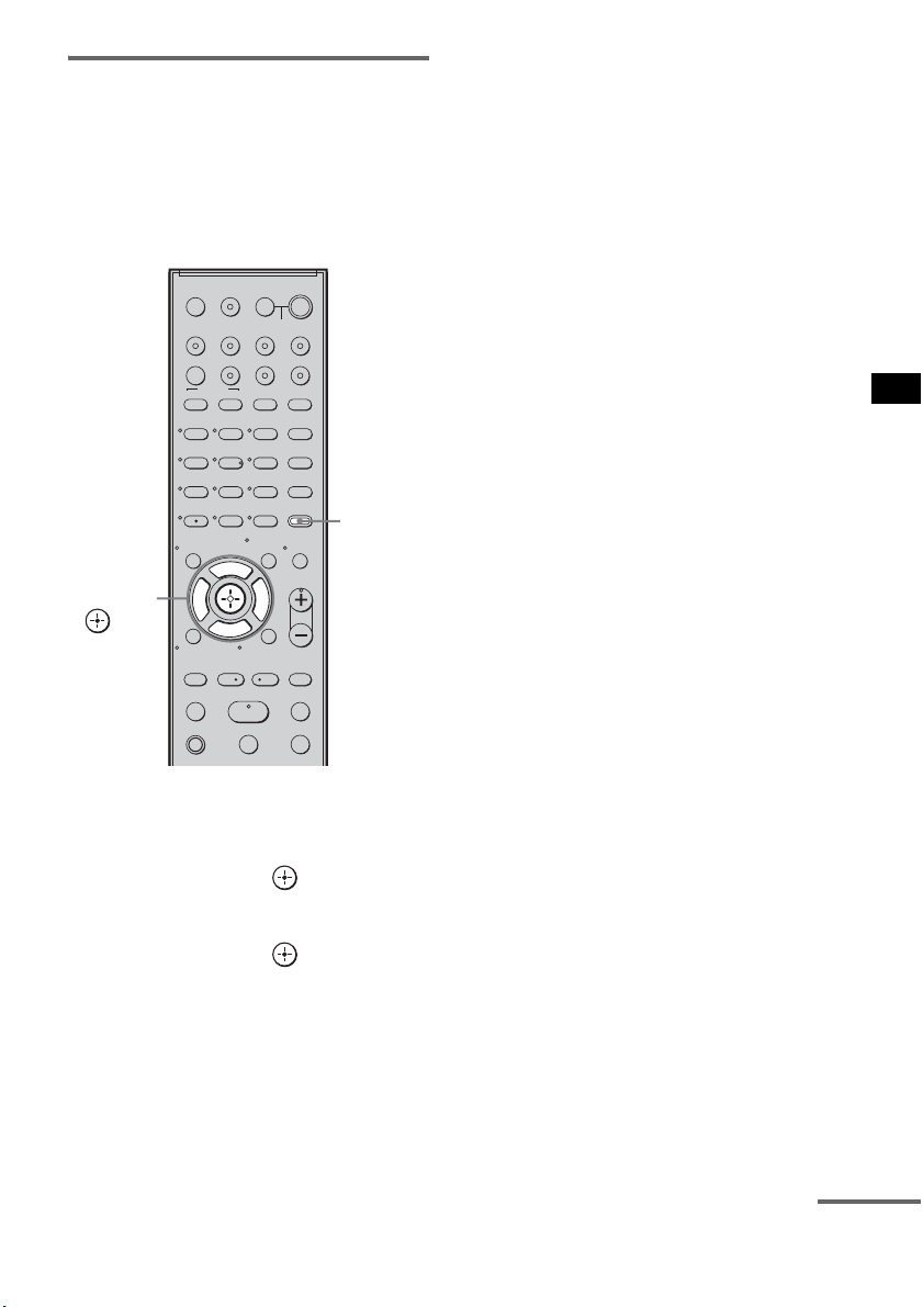
63
ES
Ajustes avanzados
Disfrutar de sonido Dolby
Digital a un volumen
moderado (AUDIO DRC)
Es posible reducir el rango dinámico de la pista
de sonido. AUDIO DRC resulta útil para ver
películas a un volumen moderado. AUDIO DRC
solo funciona con fuentes Dolby Digital.
1 Pulse AMP MENU.
2 Pulse x/X varias veces hasta que
aparezca “CUSTOMIZE” y, a
continuación, pulse o c.
3 Pulse x/X varias veces hasta que
aparezca “AUDIO DRC” y, a
continuación, pulse o c.
4 Pulse x/X para seleccionar el ajuste.
• DRC MAX: comprime totalmente el
rango dinámico.
• DRC STD: reproduce la pista de sonido
con el tipo de rango
dinámico diseñado por el
ingeniero de grabación.
• DRC OFF: no comprime el rango
dinámico.
5 Pulse AMP MENU.
El menú AMP se desactivará.
123
46
78
0
ENTER
9
TV INPUTTHEATER
TV
?/1
AV
?/1
TV BD DVD SAT
TOP MENU MENU
BD/DVD
RETURN/EXIT
TV
REPLAY ADVANCE
F1 F2
AMP MENU
CLEAR
DISPLAY
MUTING
TONE
TUNING - TUNING +
NIGHT
MODE
GUIDE
FAVORITEWIDEPICTUREJUMP
DMPORTTUNER/BANDVIDEO
SOUND FIELD
?/1
TV CH -
PRESET -
TV CH +
PRESET +
F
Gg
f
.
HmM
Xx
<
<
>
5
SYSTEM STANDBY
MENU/HOME
TOOLS/
OPTIONS
TV VOL
MASTER VOL
AMP
MENU
C, X, x, c,
continúa
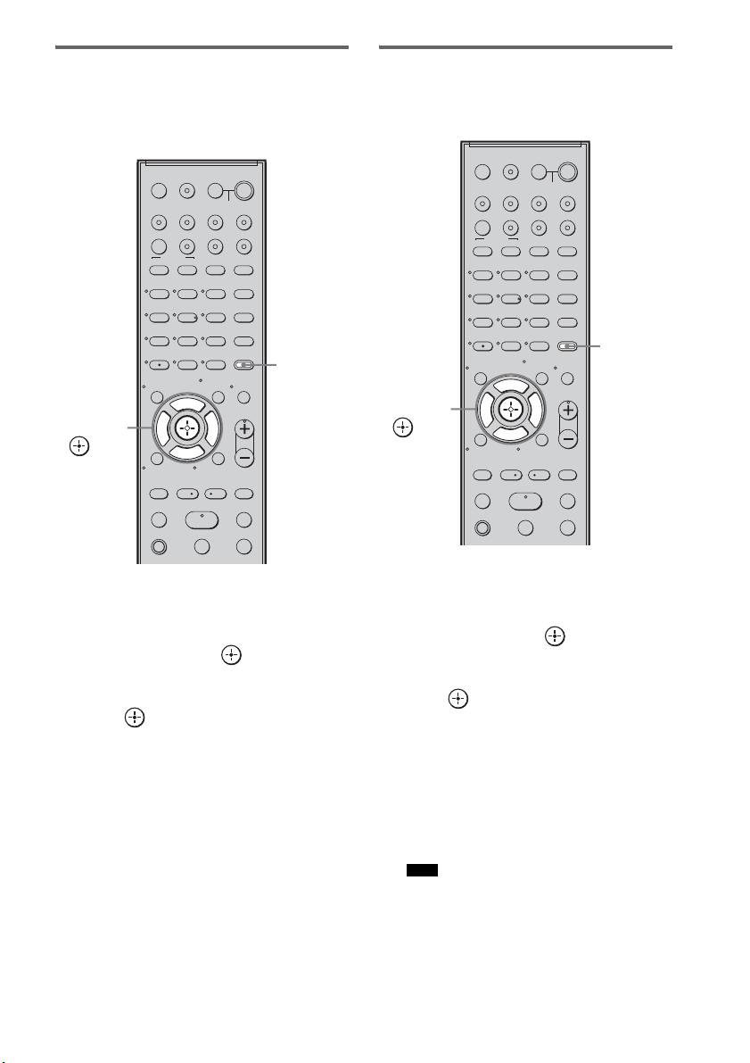
64
ES
Cambio del brillo del visor del
panel superior (DIMMER)
Puede ajustar el brillo del visor del panel
superior en cualquiera de los 2 niveles.
1 Pulse AMP MENU.
2 Pulse x/X varias veces hasta que
aparezca “CUSTOMIZE” y, a
continuación, pulse o c.
3 Pulse X/x varias veces hasta que
aparezca “DIMMER” y, a continuación,
pulse o c.
4 Pulse X/x para seleccionar el brillo del
visor del panel superior.
• DIMMER ON: luz débil.
• DIMMER OFF: luz brillante.
5 Pulse AMP MENU.
El menú AMP se desactivará.
Cambio del ajuste del visor
(DISPLAY)
Es posible cambiar el ajuste del visor.
1 Pulse AMP MENU.
2 Pulse x/X varias veces hasta que
aparezca “CUSTOMIZE” y, a
continuación, pulse o c.
3 Pulse x/X varias veces hasta que
aparezca “DISPLAY” y, a continuación,
pulse o c.
4 Pulse x/X para seleccionar el ajuste del
visor del panel superior.
• DSPL ON: el visor aparece
permanentemente.
• DSPL OFF: el visor aparece por un
instante cuando se está
manejando el sistema.
• El visor aparece permanentemente mientras las
funciones de desactivación del sonido o
protección están activadas, incluso si se ha
ajustado “DISPLAY” en “DSPL OFF”.
123
46
78
0
ENTER
9
TV INPUTTHEATER
TV
?/1
AV
?/1
TV BD DVD SAT
TOP MENU MENU
BD/DVD
RETURN/EXIT
TV
REPLAY ADVANCE
F1 F2
AMP MENU
CLEAR
DISPLAY
MUTING
TONE
TUNING - TUNING +
NIGHT
MODE
GUIDE
FAVORITEWIDEPICTUREJUMP
DMPORTTUNER/BANDVIDEO
SOUND FIELD
?/1
TV CH -
PRESET -
TV CH +
PRESET +
F
Gg
f
.
HmM
Xx
<
<
>
5
SYSTEM STANDBY
MENU/HOME
TOOLS/
OPTIONS
TV VOL
MASTER VOL
AMP
MENU
C, X, x, c,
Nota
123
46
78
0
ENTER
9
TV INPUTTHEATER
TV
?/1
AV
?/1
TV BD DVD SAT
TOP MENU MENU
BD/DVD
RETURN/EXIT
TV
REPLAY ADVANCE
F1 F2
AMP MENU
CLEAR
DISPLAY
MUTING
TONE
TUNING - TUNING +
NIGHT
MODE
GUIDE
FAVORITEWIDEPICTUREJUMP
DMPORTTUNER/BANDVIDEO
SOUND FIELD
?/1
TV CH -
PRESET -
TV CH +
PRESET +
F
Gg
f
.
HmM
Xx
<
<
>
5
SYSTEM STANDBY
MENU/HOME
TOOLS/
OPTIONS
TV VOL
MASTER VOL
AMP
MENU
C, X, x, c,
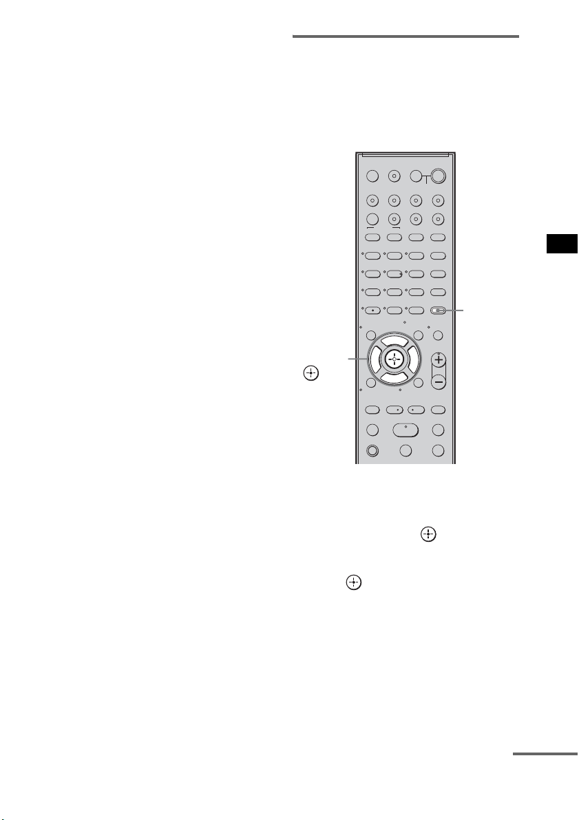
65
ES
Ajustes avanzados
5 Pulse AMP MENU.
El menú AMP se desactivará.
Uso del temporizador de
apagado (SLEEP)
Puede ajustar el sistema para que se apague en un
tiempo predeterminado cuando se duerma
escuchando música. El tiempo puede
programarse en intervalos de 10 minutos.
1 Pulse AMP MENU.
2 Pulse x/X varias veces hasta que
aparezca “CUSTOMIZE” y, a
continuación, pulse o c.
3 Pulse x/X varias veces hasta que
aparezca “SLEEP” y, a continuación,
pulse o c.
123
46
78
0
ENTER
9
TV INPUTTHEATER
TV
?/1
AV
?/1
TV BD DVD SAT
TOP MENU MENU
BD/DVD
RETURN/EXIT
TV
REPLAY ADVANCE
F1 F2
AMP MENU
CLEAR
DISPLAY
MUTING
TONE
TUNING - TUNING +
NIGHT
MODE
GUIDE
FAVORITEWIDEPICTUREJUMP
DMPORTTUNER/BANDVIDEO
SOUND FIELD
?/1
TV CH -
PRESET -
TV CH +
PRESET +
F
Gg
f
.
HmM
Xx
<
<
>
5
SYSTEM STANDBY
MENU/HOME
TOOLS/
OPTIONS
TV VOL
MASTER VOL
AMP
MENU
C, X, x, c,
continúa

66
ES
4 Pulse x/X para seleccionar el tiempo
predeterminado.
La visualización de minutos (el tiempo
restante) cambiará de la siguiente manera:
5 Pulse AMP MENU.
El menú AMP se desactivará.
• Esta función solo es válida para este sistema, no para
el televisor conectado ni para el resto de componentes.
Reasignación de la entrada de
audio analógica
Es posible reasignar una entrada de audio con
señal de audio (analógica) a la función “TV”,
“BD”, “DVD”, “SAT” o “VIDEO”, si ésta no se
utiliza.
Por ejemplo, para emitir la fuente de audio para
el reproductor de DVD utilizando las tomas
AUDIO IN ASSIGNABLE del altavoz
potenciador de graves:
• Conecte las entradas de salida analógica del
reproductor de DVD a las tomas AUDIO IN
ASSIGNABLE del altavoz potenciador de
graves.
• Asigne la función “DVD” a “ANALOG DVD”
en el ajuste “A. ASSIGN”.
1 Pulse AMP MENU.
Nota
OFF y 10M y 20M
YY
90M y 80M ..... 30M
Reasignación de las
entradas de audio
123
46
78
0
ENTER
9
TV INPUTTHEATER
TV
?/1
AV
?/1
TV BD DVD SAT
TOP MENU MENU
BD/DVD
RETURN/EXIT
TV
REPLAY ADVANCE
F1 F2
AMP MENU
CLEAR
DISPLAY
MUTING
TONE
TUNING - TUNING +
NIGHT
MODE
GUIDE
FAVORITEWIDEPICTUREJUMP
DMPORTTUNER/BANDVIDEO
SOUND FIELD
?/1
TV CH -
PRESET -
TV CH +
PRESET +
F
Gg
f
.
HmM
Xx
<
<
>
5
SYSTEM STANDBY
MENU/HOME
TOOLS/
OPTIONS
TV VOL
MASTER VOL
AMP
MENU
C, X, x, c,
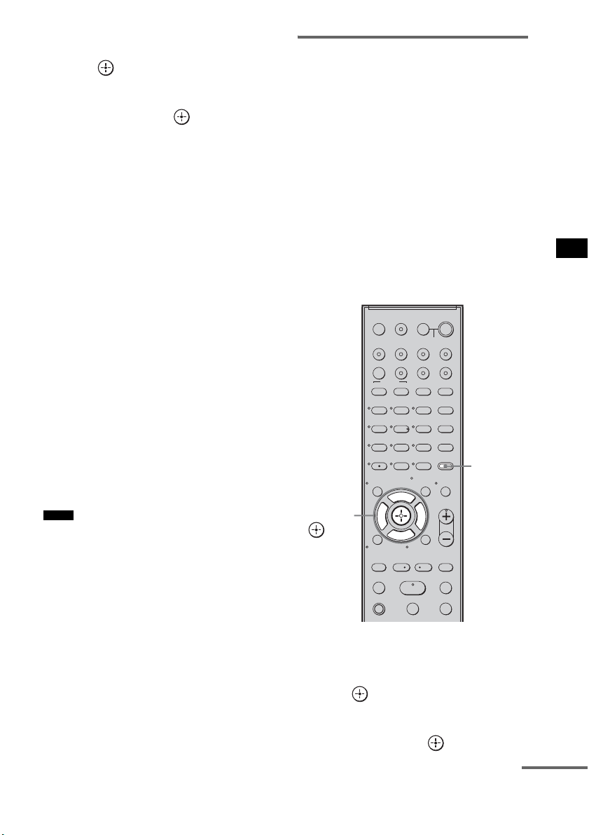
67
ES
Ajustes avanzados
2 Pulse x/X varias veces hasta que
aparezca “AUDIO” y, a continuación,
pulse o c.
3 Pulse x/X varias veces hasta que
aparezca “A. ASSIGN” y, a
continuación, pulse o c.
4 Pulse x/X para seleccionar la entrada
de audio que desee reasignar.
• ANALOG VD: permite reasignar la
entrada de audio
analógica a la función
“VIDEO”.
• ANALOG TV: permite reasignar la
entrada de audio
analógica a la función
“TV”.
• ANALOG SAT: permite reasignar la
entrada de audio
analógica a la función
“SAT”.
• ANALOG DVD: permite reasignar la
entrada de audio
analógica a la función
“DVD”.
• ANALOG BD: permite reasignar la
entrada de audio
analógica a la función
“BD”.
5 Pulse AMP MENU.
El menú AMP se desactivará.
• Cuando se emiten imágenes de un componente de
audio, es posible que el sonido no se emita. En ese
caso, compruebe lo siguiente:
– Confirme que las tomas de entrada de audio
analógica se corresponden con la función.
– Reasigne la función.
• No podrá utilizar la entrada de audio analógica para la
entrada original si se ha reasignado a otra entrada.
• No podrá reasignar la entrada de audio analógica a la
función “TUNER/BAND” ni “DMPORT”.
Reasignación de la entrada de
audio digital
Es posible reasignar una entrada de audio con
señal coaxial (digital) a la función “DVD” o
“SAT” si alguna de estas dos funciones no se
utiliza.
Por ejemplo, para emitir la fuente de audio para
el reproductor de DVD utilizando la toma
ASSIGNABLE COAXIAL SAT IN del altavoz
potenciador de graves:
• Conecte las entradas de salida coaxial del
reproductor de DVD a la toma ASSIGNABLE
COAXIAL SAT IN del altavoz potenciador de
graves.
• Asigne la función “DVD” a “COAX DVD” en
el ajuste “D. ASSIGN”.
1 Pulse AMP MENU.
2 Pulse x/X varias veces hasta que
aparezca “AUDIO” y, a continuación,
pulse o c.
3 Pulse x/X varias veces hasta que
aparezca “D. ASSIGN” y, a
continuación, pulse o c.
Notas
123
46
78
0
ENTER
9
TV INPUTTHEATER
TV
?/1
AV
?/1
TV BD DVD SAT
TOP MENU MENU
BD/DVD
RETURN/EXIT
TV
REPLAY ADVANCE
F1 F2
AMP MENU
CLEAR
DISPLAY
MUTING
TONE
TUNING - TUNING +
NIGHT
MODE
GUIDE
FAVORITEWIDEPICTUREJUMP
DMPORTTUNER/BANDVIDEO
SOUND FIELD
?/1
TV CH -
PRESET -
TV CH +
PRESET +
F
Gg
f
.
HmM
Xx
<
<
>
5
SYSTEM STANDBY
MENU/HOME
TOOLS/
OPTIONS
TV VOL
MASTER VOL
AMP
MENU
C, X, x, c,
continúa
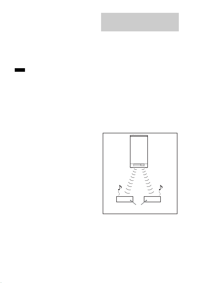
68
ES
4 Pulse x/X para seleccionar la entrada
de audio que desee reasignar.
• COAX SAT: permite reasignar la entrada
de audio coaxial a la
función “SAT”.
• COAX DVD: permite reasignar la entrada
de audio coaxial a la
función “DVD”.
5 Pulse AMP MENU.
El menú AMP se desactivará.
• No es posible reasignar varias entradas de audio
digital a la misma entrada.
• No podrá utilizar la entrada de audio digital para la
entrada original si se ha reasignado a otra entrada.
• No podrá reasignar la entrada de audio digital a la
función “TV”, “BD”, “VIDEO”, “TUNER/BAND” o
“DMPORT”.
Acerca de los productos S-AIR
El sistema es compatible con la función S-AIR,
que permite transmitir sonido entre el altavoz
potenciador de graves y un producto S-AIR (no
suministrado).
Al adquirir un producto S-AIR, debe llevar a
cabo los siguientes ajustes para poder establecer
la transmisión de sonido.
Existen dos clases de productos S-AIR.
• La unidad principal S-AIR (este altavoz
potenciador de graves): sirve para transmitir el
sonido. Puede utilizar hasta un máximo
de tres unidades principales S-AIR. (El número
de unidades principales S-AIR utilizables
depende del entorno de uso.)
• Unidad secundaria S-AIR: sirve para recibir el
sonido.
Notas
Utilización de un producto
S-AIR
Unidad
principal
S-AIR
Unidad secundaria S-AIR
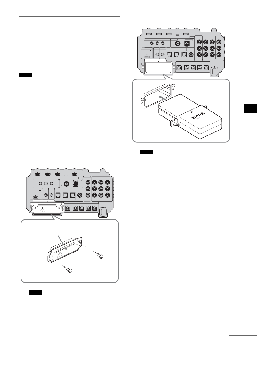
69
ES
Ajustes avanzados
Inserción del transmisor/
transceptor inalámbrico
Para utilizar la función S-AIR, debe insertar el
transmisor inalámbrico (no suministrado) en el
altavoz potenciador de graves y el transceptor
inalámbrico (no suministrado) en el producto
S-AIR.
• Al insertar el transmisor/transceptor inalámbrico,
asegúrese de que el cable de alimentación de CA no
está conectado a una toma de pared.
• No toque los terminales del transmisor/transceptor
inalámbrico.
Para insertar el transmisor
inalámbrico en el altavoz
potenciador de graves
1 Quite los tornillos y retire la tapa de la
ranura.
• Quite solo los tornillos de la tapa de la ranura que
vienen indicados con una señal de advertencia.
No retire ningún otro tornillo.
• Ya no necesitará la tapa de la ranura; sin
embargo, recomendamos que la guarde.
2 Inserte el transmisor inalámbrico.
• Inserte el transmisor inalámbrico con el logotipo
de S-AIR mirando hacia arriba.
• Inserte el transmisor inalámbrico de tal modo
que las marcas
V queden alineadas.
• Inserte únicamente el transmisor inalámbrico en
la ranura EZW-T100.
Notas
Notas
IR REMOTE
VIDEO
DMPORT
DIGITAL COMPONENT VIDEO
SPEAKER ONLY FOR SS-IS15
ECM-AC2 IR-R100
ANTENNA
HDMI
IR IN IR OUT1 IR OUT2
FM AM
75
COAXIAL
DC 5V
0.7A MAX
FRONT R FRONT L SUR R SUR LCENTER
BD IN DVD IN SAT IN
TV IN DVD IN SAT IN SAT IN
ASSIGNABLE
COAXIAL
AUDI O IN
ASSIGNABLE
VIDEO IN
DVD IN SAT IN
MONITOR
OUT
L
Y
P
B
/
C
B
P
R
/
C
R
R
OPTICAL
TV OUT
EZW-T100
E
Z
W
-
T
1
0
0
Tapa de la ranura
Parte inferior del altavoz
potenciador de graves
Notas
IR REMOTE
VIDEO
DMPORT
DIGITAL COMPONENT VIDEO
SPEAKER ONLY FOR SS-IS15
ECM-AC2 IR-R100
ANTENNA
HDMI
IR IN IR OUT1 IR OUT2
FM AM
75
COAXIAL
DC 5V
0.7A MAX
FRONT R FRONT L SUR R SUR LCENTER
BD IN DVD IN SAT IN
TV IN DVD IN SAT IN SAT IN
ASSIGNABLE
COAXIAL
AUDI O IN
ASSIGNABLE
VIDEO IN
DVD IN SAT IN
MONITOR
OUT
L
Y
P
B
/
C
B
P
R
/
C
R
R
OPTICAL
TV OUT
EZW-T100
E
Z
W
-
T
1
0
0
continúa
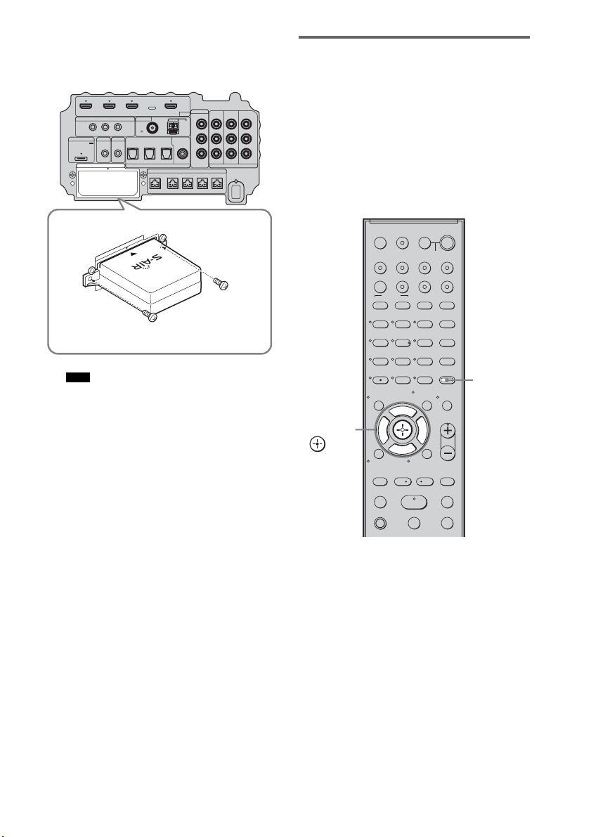
70
ES
3 Asegúrese de utilizar los mismos
tornillos para fijar el transmisor
inalámbrico.
• No utilice otros tornillos para fijar el transmisor
inalámbrico.
Para insertar el transceptor
inalámbrico en el producto S-AIR
Si desea información detallada sobre cómo
instalar el transceptor inalámbrico en el producto
S-AIR, consulte el manual de instrucciones del
producto S-AIR correspondiente.
Establecimiento de la
transmisión de sonido entre el
altavoz potenciador de graves
y el producto S-AIR
Para establecer la transmisión de sonido,
configure los productos S-AIR que esté
utilizando.
Tras insertar el transmisor/transceptor
inalámbrico, conecte el cable de alimentación de
CA.
Para configurar la ID del altavoz
potenciador de graves
Para establecer la transmisión de sonido basta
con vincular la ID del altavoz potenciador de
graves con el producto S-AIR. Pueden utilizarse
varios productos S-AIR; para ello, hay que
configurar una ID distinta para cada
componente.
1 Encienda el altavoz potenciador de
graves.
El altavoz potenciador de graves se
enciende.
Nota
IR REMOTE
VIDEO
DMPORT
DIGITAL COMPONENT VIDEO
SPEAKER ONLY FOR SS-IS15
ECM-AC2 IR-R100
ANTENNA
HDMI
IR IN IR OUT1 IR OUT2
FM AM
75
COAXIAL
DC 5V
0.7A MAX
FRONT R FRONT L SUR R SUR LCENTER
BD IN DVD IN SAT IN
TV IN DVD IN SAT IN SAT IN
ASSIGNABLE
COAXIAL
AUDI O IN
ASSIGNABLE
VIDEO IN
DVD IN SAT IN
MONITOR
OUT
L
Y
P
B
/
C
B
P
R
/
C
R
R
OPTICAL
TV OUT
EZW-T100
E
Z
W
-
T
1
0
0
123
46
78
0
ENTER
9
TV INPUTTHEATER
TV
?/1
AV
?/1
TV BD DVD SAT
TOP MENU MENU
BD/DVD
RETURN/EXIT
TV
REPLAY ADVANCE
F1 F2
AMP MENU
CLEAR
DISPLAY
MUTING
TONE
TUNING - TUNING +
NIGHT
MODE
GUIDE
FAVORITEWIDEPICTUREJUMP
DMPORTTUNER/BANDVIDEO
SOUND FIELD
?/1
TV CH -
PRESET -
TV CH +
PRESET +
F
Gg
f
.
HmM
Xx
<
<
>
5
SYSTEM STANDBY
MENU/HOME
TOOLS/
OPTIONS
TV VOL
MASTER VOL
AMP
MENU
C, X, x, c,
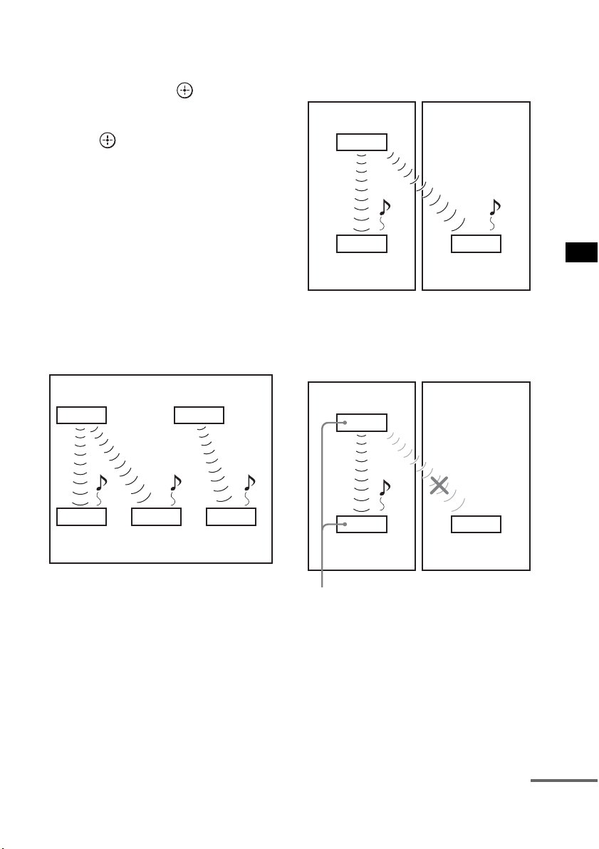
71
ES
Ajustes avanzados
2 Pulse AMP MENU.
3 Pulse x/X varias veces hasta que
aparezca “S-AIR SET” y, a
continuación, pulse o c.
4 Pulse x/X varias veces hasta que
aparezca “S-AIR ID” y, a continuación,
pulse o c.
5 Pulse x/X varias veces para
seleccionar la ID deseada (A, B o C).
6 Pulse AMP MENU.
El menú AMP se desactivará.
Para configurar la ID del producto
S-AIR
Si desea información detallada sobre cómo
configurar la ID del producto S-AIR, consulte el
manual de instrucciones del producto S-AIR
correspondiente.
Imagen del establecimiento de la
transmisión de sonido
Para realizar el emparejamiento
Configurar la misma ID para el altavoz
potenciador de graves y el producto S-AIR para
establecer la transmisión de sonido es muy
sencillo. Sin embargo, es posible que sus vecinos
también reciban el sonido de su sistema si las ID
son las mismas, o que usted reciba el sonido de
los vecinos. Para evitar esto, puede vincular el
altavoz potenciador de graves con un producto
S-AIR específico realizando un emparejamiento.
x Al realizar el emparejamiento
Antes de realizar el emparejamiento, se establece
la transmisión de sonido mediante ID (ejemplo).
Se establece la transmisión de sonido entre el
altavoz potenciador de graves y el producto o los
productos S-AIR emparejados.
1 Coloque el producto S-AIR que desee
emparejar cerca del altavoz
potenciador de graves.
Unidad principal S-AIR
A
(este
altavoz potenciador de graves)
Producto
S-AIR A
Unidad principal
S-AIR B
Producto
S-AIR B
Producto
S-AIR C
ID A ID A ID B
ID A ID B
Su sala Vecino
ID A ID A
ID A
Producto
S-AIR A
Producto
S-AIR B
Unidad principal S-AIR
A
(este
altavoz potenciador de graves)
Su sala Vecino
ID A ID A
ID A
Producto
S-AIR A
Producto
S-AIR B
Emparejamiento
Unidad principal S-AIR
A
(este
altavoz potenciador de graves)
continúa

72
ES
2 Haga coincidir la ID del altavoz
potenciador de graves con el producto
S-AIR. Para configurar la ID del
sistema, consulte “Para configurar la ID
del altavoz potenciador de graves”
(página 70).
Para configurar la ID del producto S-AIR,
consulte el manual de instrucciones del
producto S-AIR correspondiente.
3 Pulse AMP MENU.
4 Pulse x/X varias veces hasta que
aparezca “S-AIR SET” y, a
continuación, pulse o c.
5 Pulse x/X varias veces hasta que
aparezca “PAIRING” y, a continuación,
pulse o c.
6 Pulse x/X varias veces para
seleccionar el ajuste deseado y, a
continuación, pulse o c.
• START: el altavoz potenciador de
graves inicia el
emparejamiento.
• CONDITION: permite comprobar la ID
actual. Cuando no se ha
llevado a cabo ningún
ajuste de emparejamiento,
aparece “NO PAIRING”
en el visor del panel
superior.
7 Inicie el emparejamiento del producto
S-AIR.
Para iniciar el emparejamiento del producto
S-AIR, consulte el manual de instrucciones
del producto S-AIR correspondiente.
Cuando se establece la transmisión de
sonido, aparece “COMPLETE” en el visor
del panel superior.
8 Pulse AMP MENU.
El menú AMP se desactivará.
• Realice el emparejamiento del producto S-AIR antes
de que transcurran varios minutos desde el paso 6. De
lo contrario, el emparejamiento se cancela
automáticamente y aparece “INCOMPLETE” en el
visor del panel superior.
Para cancelar el emparejamiento
Configure la ID del altavoz potenciador de
graves según el procedimiento de “Para
configurar la ID del altavoz potenciador de
graves” (página 70). Si selecciona una ID nueva
(puede seleccionar la misma ID que antes), el
emparejamiento se cancela.
Nota
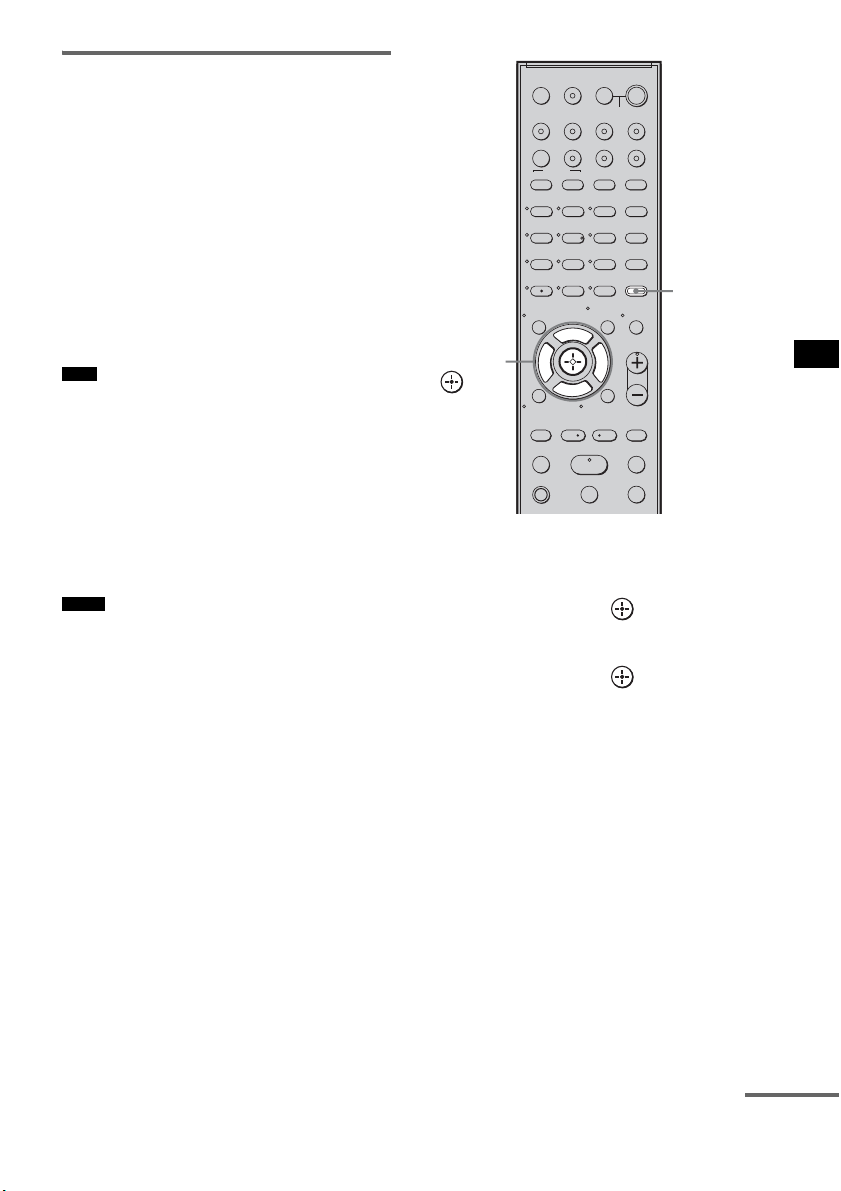
73
ES
Ajustes avanzados
Disfrutar del sonido del
sistema utilizando el producto
S-AIR
Puede disfrutar del sonido del sistema utilizando
un producto S-AIR compatible con el modo
S-AIR. El producto S-AIR puede instalarse en
cualquier lugar, con independencia de la
ubicación del altavoz potenciador de graves, y
así poder recibir el sonido del sistema en otra
sala.
Si desea más información sobre el producto
S-AIR, consulte el manual de instrucciones del
producto S-AIR correspondiente.
• Es posible que las fuentes con protección de derechos
de autor no puedan reproducirse en productos S-AIR.
1 Configure la ID del producto S-AIR
según la ID del altavoz potenciador de
graves.
Para configurar la ID del altavoz
potenciador de graves, consulte “Para
configurar la ID del altavoz potenciador de
graves” (página 70).
• Cuando utilice otro producto S-AIR, no cambie la ID
del altavoz potenciador de graves. Configure la ID
del producto S-AIR según la ID del altavoz
potenciador de graves.
• Al vincular el altavoz potenciador de graves y otro
producto S-AIR mediante la operación de
emparejamiento, es necesario realizar un
emparejamiento entre el altavoz potenciador de
graves y el producto S-AIR. Si desea más
información, consulte “Para realizar el
emparejamiento” (página 71).
2 Pulse AMP MENU.
3 Pulse x/X varias veces hasta que
aparezca “S-AIR SET” y, a
continuación, pulse o c.
4 Pulse x/X varias veces hasta que
aparezca “S-AIR MODE” y, a
continuación, pulse o c.
5 Pulse x/X varias veces para
seleccionar la función deseada.
• PARTY: el producto S-AIR emite
sonido según la función
configurada en el altavoz
potenciador de graves.
• SEPARATE: permite configurar la
función deseada para el
producto S-AIR sin variar
las funciones del altavoz
potenciador de graves.
Si se ha seleccionado
“SEPARATE”, las
funciones que puede
seleccionar son “MAIN
UNIT”, “TUNER FM”,
“TUNER AM” y
“DMPORT”.
Nota
Notas
123
46
78
0
ENTER
9
TV INPUTTHEATER
TV
?/1
AV
?/1
TV BD DVD SAT
TOP MENU MENU
BD/DVD
RETURN/EXIT
TV
REPLAY ADVANCE
F1 F2
AMP MENU
CLEAR
DISPLAY
MUTING
TONE
TUNING - TUNING +
NIGHT
MODE
GUIDE
FAVORITEWIDEPICTUREJUMP
DMPORTTUNER/BANDVIDEO
SOUND FIELD
?/1
TV CH -
PRESET -
TV CH +
PRESET +
F
Gg
f
.
HmM
Xx
<
<
>
5
SYSTEM STANDBY
MENU/HOME
TOOLS/
OPTIONS
TV VOL
MASTER VOL
AMP
MENU
C, X, x, c,
continúa
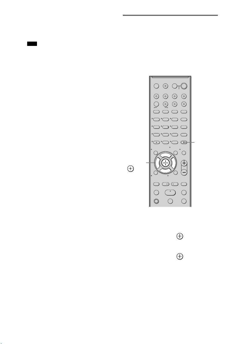
74
ES
Para utilizar la misma
función que el altavoz
potenciador de graves,
seleccione “MAIN UNIT”.
• Si se ha seleccionado “TUNER FM” o “TUNER
AM” en el altavoz potenciador de graves, solo
podrá seleccionar la misma banda que el
sintonizador del producto S-AIR.
6 Pulse AMP MENU.
El menú AMP se desactivará.
7 Seleccione la función deseada en el
producto S-AIR.
Cuando el sonido no es estéreo a 2 canales,
el sonido multicanal se reduce a 2 canales.
8 Ajuste el volumen del producto S-AIR.
Cambio de canal para mejorar
la transmisión de sonido
Si la transmisión de sonido es inestable, puede
mejorarla cambiando el ajuste “RF CHANGE”.
El ajuste óptimo es distinto según el entorno de
uso.
En la mayoría de los casos, no será necesario
cambiar este ajuste.
1 Pulse AMP MENU.
2 Pulse x/X varias veces hasta que
aparezca “S-AIR SET” y, a
continuación, pulse o c.
3 Pulse x/X varias veces para
seleccionar “RF CHANGE” y, a
continuación, pulse o c.
4 Pulse x/X varias veces para
seleccionar el ajuste deseado.
• AUTO: seleccione esta opción como
norma general. El altavoz
potenciador de graves cambia
“RF CHANGE” a “ON” o a
“OFF” automáticamente.
Nota
123
46
78
0
ENTER
9
TV INPUTTHEATER
TV
?/1
AV
?/1
TV BD DVD SAT
TOP MENU MENU
BD/DVD
RETURN/EXIT
TV
REPLAY ADVANCE
F1 F2
AMP MENU
CLEAR
DISPLAY
MUTING
TONE
TUNING - TUNING +
NIGHT
MODE
GUIDE
FAVORITEWIDEPICTUREJUMP
DMPORTTUNER/BANDVIDEO
SOUND FIELD
?/1
TV CH -
PRESET -
TV CH +
PRESET +
F
Gg
f
.
HmM
Xx
<
<
>
5
SYSTEM STANDBY
MENU/HOME
TOOLS/
OPTIONS
TV VOL
MASTER VOL
AMP
MENU
C, X, x, c,
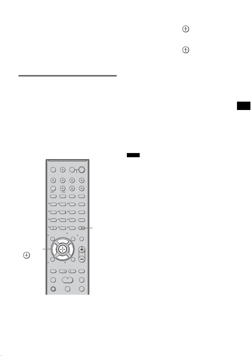
75
ES
Ajustes avanzados
• ON: el altavoz potenciador de graves
transmite sonido buscando el
mejor canal para ello.
• OFF: el altavoz potenciador de graves
transmite sonido a través de un
canal fijo.
5 Pulse AMP MENU.
El menú AMP se desactivará.
Para utilizar el producto S-AIR
cuando el altavoz potenciador
de graves se encuentra en
modo de espera
Es posible utilizar el producto S-AIR mientras el
altavoz potenciador de graves se encuentra en
modo de espera ajustando “S-AIR STBY” a
“STBY ON”.
Cuando use la función de temporizador del
producto S-AIR, ajuste “S-AIR STBY” en
“STBY ON”.
1 Pulse AMP MENU.
2 Pulse x/X varias veces hasta que
aparezca “S-AIR SET” y, a
continuación, pulse o c.
3 Pulse x/X varias veces para
seleccionar “S-AIR STBY” y, a
continuación, pulse o c.
4 Pulse x/X varias veces para
seleccionar el ajuste deseado.
• STBY OFF: no es posible utilizar el
producto S-AIR cuando el
altavoz potenciador de
graves se encuentra en modo
de espera.
• STBY ON: es posible utilizar el
producto S-AIR cuando el
altavoz potenciador de
graves se encuentra en modo
de espera o encendido.
5 Pulse AMP MENU.
El menú AMP se desactivará.
• Cuando se ajusta “S-AIR STBY” a “STBY ON”,
aumenta el consumo de electricidad durante el modo
de espera.
• El sonido del producto S-AIR puede verse
interrumpido al utilizar el altavoz potenciador de
graves.
123
46
78
0
ENTER
9
TV INPUTTHEATER
TV
?/1
AV
?/1
TV BD DVD SAT
TOP MENU MENU
BD/DVD
RETURN/EXIT
TV
REPLAY ADVANCE
F1 F2
AMP MENU
CLEAR
DISPLAY
MUTING
TONE
TUNING - TUNING +
NIGHT
MODE
GUIDE
FAVORITEWIDEPICTUREJUMP
DMPORTTUNER/BANDVIDEO
SOUND FIELD
?/1
TV CH -
PRESET -
TV CH +
PRESET +
F
Gg
f
.
HmM
Xx
<
<
>
5
SYSTEM STANDBY
MENU/HOME
TOOLS/
OPTIONS
TV VOL
MASTER VOL
AMP
MENU
C, X, x, c,
Notas
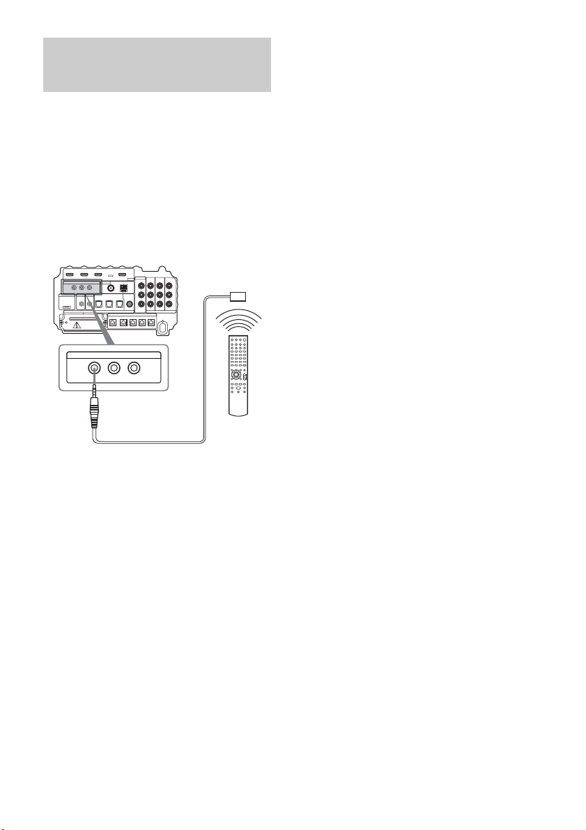
76
ES
Acerca de las tomas IR REMOTE
Es posible controlar el altavoz potenciador de
graves sin apuntar el mando a distancia hacia el
receptor si se conecta un repetidor de infrarrojos
(no suministrado) a la toma IR REMOTE.
Utilice un repetidor de infrarrojos si instala el
receptor del mando a distancia en un lugar donde
las señales no llegan.
Utilización del repetidor
de infrarrojos
IR REMOTE
IR IN IR OUT1 IR OUT2
Parte inferior del altavoz potenciador de graves
Repetidor de
infrarrojos (no
suministrado)
Mando a
distancia

77
ES
Información complementaria
Si le surge cualquiera de las siguientes
dificultades mientras emplea el sistema, utilice
esta guía de solución de problemas para resolver
el problema antes de solicitar asistencia técnica.
Si el problema persiste, consulte con el
distribuidor Sony más próximo. En caso de
reparación, asegúrese de entregar todo el
sistema.
Especificaciones generales
La alimentación no se activa.
• Compruebe que el cable de alimentación de
CA está correctamente conectado.
Si aparece alternativamente “PROTECTOR” y
“PUSH POWER” en el visor del panel superior.
Pulse ?/1 para apagar el sistema y compruebe
que el elemento que sigue a “STANDBY”
desaparece.
• Compruebe que no hay nada que bloquee los
orificios de ventilación del sistema.
Una vez que haya realizado dicha
comprobación y solucionado cualquier
problema, encienda el sistema. Si no es
capaz de detectar la causa del problema
incluso después de haber comprobado el
elemento anterior, póngase en contacto con
su distribuidor Sony más cercano.
El sonido Dolby Digital o DTS multicanal no se
reproduce.
• Compruebe que el Blu-ray Disc, DVD u otro
soporte que está reproduciendo se ha
grabado en formato Dolby Digital o DTS.
• Compruebe el ajuste de audio (los ajustes de
la salida de audio) del componente
conectado.
No es posible obtener el efecto de sonido
envolvente.
• En función de la señal digital, es posible que
el procesamiento de sonido envolvente no
funcione (página 39).
No hay sonido o sólo se emite sonido muy
bajo desde los altavoces.
• Pulse MASTER VOL + y compruebe el
nivel de volumen.
• Pulse MUTING o MASTER VOL + para
cancelar la función de desactivación del
sonido.
• Pulse SOUND FIELD y verifique el campo
acústico seleccionado.
• Según la fuente, el efecto de sonido de los
altavoces puede ser menos perceptible.
El sonido procede solo del altavoz central.
• Compruebe las conexiones y los ajustes del
altavoz (página 15, 58).
• En función del disco, puede que el sonido
proceda solo del altavoz central.
No se emite sonido del altavoz central.
• Compruebe las conexiones y los ajustes del
altavoz (página 15, 58).
• Ajuste el campo de sonido en un nivel que
no sea “OMNI-DIRECTIONAL SOUND”
(página 39).
• En función de la fuente, el efecto de sonido
del altavoz central puede ser menos
perceptible.
No hay sonido o solo se emite sonido muy
bajo desde los altavoces de sonido
envolvente.
• Compruebe las conexiones y los ajustes del
altavoz (página 15, 58).
• Compruebe el campo de sonido
seleccionado (página 39).
• En función de la fuente, el efecto de sonido
de los altavoces de sonido envolvente puede
ser menos perceptible.
• Se reproduce una señal monoaural o estéreo
(que no es multicanal).
El sonido se emite con retraso en
comparación con la imagen del televisor.
• Ajuste “A/V SYNC” en “SYNC OFF” si
“A/V SYNC” está ajustado.
Información complementaria
Solución de problemas
continúa

78
ES
Componentes conectados
No hay sonido o el que hay es muy bajo,
independientemente del componente que se
seleccione.
• Compruebe que este sistema y los
componentes están correctamente
conectados y con firmeza.
• Compruebe que tanto el sistema como el
componente seleccionado están encendidos.
El componente seleccionado no emite ningún
sonido.
• Verifique que el componente esté conectado
correctamente a las tomas de entrada de
audio de dicho componente.
• Compruebe que los cables estén totalmente
insertados en las tomas del componente y del
sistema.
• Compruebe que el componente está
correctamente seleccionado.
• Si reanuda la reproducción de un disco con
el volumen al máximo, es posible que no se
produzca ningún sonido. En este caso, baje
el volumen, apague el sistema y vuelva a
encenderlo.
El sonido se interrumpe o se escucha ruido.
• Consulte los formatos de audio de salida
compatibles con este sistema (página 80).
No hay imagen en la pantalla del televisor o la
que se muestra es borrosa.
• Seleccione la entrada adecuada con los
botones de entrada.
• Ajuste el televisor en el modo de entrada
correcto.
• Aleje los componentes de audio del
televisor.
• En función del adaptador DIGITAL MEDIA
PORT, tal vez no sea posible emitir vídeo.
La imagen original que recibe la toma HDMI del
altavoz potenciador de graves no se emite
desde el televisor.
• Compruebe la conexión HDMI.
• En función del componente de
reproducción, puede que deba configurarlo.
Consulte el manual de instrucciones
suministrado con cada componente.
Aparecen imágenes en la pantalla del televisor
pero no hay sonido.
• Compruebe que el ajuste asignable de audio
es correcto (página 66, 67).
Control por HDMI
La función Control por HDMI no funciona.
• Compruebe la conexión HDMI (página 16).
• Asegúrese de que “CTRL: HDMI” está
ajustado en “CTRL ON” en el menú AMP.
• Asegúrese de que el componente conectado
es compatible con la función Control por
HDMI.
• Compruebe los ajustes de Control por
HDMI en el componente conectado. Para
obtener más información, consulte el
manual de instrucciones del componente.
• Si cambia la conexión HDMI o bien conecta
o desconecta el cable de alimentación de CA
o si se produce un corte en la alimentación,
repita los pasos de “Preparativos para
utilizar “BRAVIA” Sync” (página 43).
• Puede que el sistema no funcione
correctamente si selecciona un componente
no compatible con la función Control por
HDMI del televisor.
No se emite sonido ni del sistema ni del
altavoz del televisor.
• Compruebe el volumen del sistema y del
televisor.
• Seleccione correctamente la entrada del
sistema.
El sonido se emite desde el sistema y también
desde el televisor.
• Si la función Control por HDMI está
desactivada o el componente seleccionado
no es compatible con dicha función,
desactive el sonido del sistema o del
televisor.
La función Apagado del sistema no funciona.
• Cambie el ajuste del televisor para apagar
los componentes conectados
automáticamente al apagar el televisor. Para
obtener más información, consulte el
manual de instrucciones del televisor.

79
ES
Información complementaria
Una imagen no aparece en el televisor.
• Compruebe si HDMI IN y HDMI OUT están
bien conectadas.
Función S-AIR
No se establece la transmisión de sonido.
• Si utiliza otra unidad principal S-AIR,
colóquela a más de 8 m (26
1
/4 pies) de
distancia del sistema.
• Confirme la ID del altavoz potenciador de
graves y del producto S-AIR (página 70).
• Ha emparejado el altavoz potenciador de
graves y otro producto S-AIR. Empareje el
producto S-AIR deseado (página 71).
• El producto S-AIR está emparejado con otro
producto S-AIR. Cancele el
emparejamiento.
• Instale el sistema en una posición alejada de
otros productos inalámbricos.
• Deje de utilizar el otro producto
inalámbrico.
• El producto S-AIR está apagado. Asegúrese
de que el cable de alimentación de CA está
conectado y encienda el producto S-AIR.
No se emite sonido del producto S-AIR.
• Si utiliza otra unidad principal S-AIR,
colóquela a más de 8 m (26
1
/4 pies) de
distancia del sistema.
• Confirme la ID del altavoz potenciador de
graves y del producto S-AIR (página 70).
• Confirme el ajuste del emparejamiento
(página 71).
• Instale la unidad principal S-AIR y la unidad
secundaria S-AIR más cerca entre sí.
• No utilice equipos que generen campos
electromagnéticos, como por ejemplo un
horno microondas.
• Instale la unidad principal S-AIR y la unidad
secundaria S-AIR en una posición alejada de
otros productos inalámbricos.
• Deje de utilizar el otro producto
inalámbrico.
• Cambie el ajuste de “RF CHANGE”
(página 74).
• Cambie los ajustes de ID de la unidad
principal S-AIR y la unidad secundaria S-AIR.
• Apague el sistema y el producto S-AIR y
vuelva a encenderlos.
Se percibe ruido o el sonido salta.
• Si utiliza otra unidad principal S-AIR,
colóquela a más de 8 m (26
1
/4 pies) de
distancia del sistema.
• Instale la unidad principal S-AIR y la unidad
secundaria S-AIR más cerca entre sí.
• No utilice equipos que generen campos
electromagnéticos, como por ejemplo un
horno microondas.
• Instale la unidad principal S-AIR y la unidad
secundaria S-AIR en una posición alejada de
otros productos inalámbricos.
• Deje de utilizar el otro producto
inalámbrico.
• Cambie el ajuste de “RF CHANGE”
(página 74).
• Cambie los ajustes de ID de la unidad
principal S-AIR y la unidad secundaria
S-AIR.
Otros
El mando a distancia no funciona.
• Compruebe que el altavoz potenciador de
graves y el receptor de mando a distancia
están correctamente conectados y con
firmeza.
• Oriente el mando a distancia hacia el sensor
( ) del receptor de mando a distancia.
• Retire cualquier obstáculo que impida la
comunicación entre el mando a distancia y el
receptor de mando a distancia.
• Sustituya las dos pilas del mando a distancia
por otras nuevas si ya no tienen carga.
• Pulse uno de los botones de entrada (TV,
BD, DVD, SAT, TUNER/BAND o
DMPORT) del mando a distancia para
seleccionar el componente que desea utilizar
(página 52).
continúa

80
ES
El volumen se apaga cuando el método de
salida cambia del altavoz del televisor al
altavoz del sistema.
• La función de límite de volumen está
activada. Para obtener más información,
consulte “Uso de la función de límite de
volumen” (página 46).
Si el sistema sigue sin funcionar
después de llevar a cabo las
medidas descritas
anteriormente, restablezca el
sistema del modo siguiente:
Utilice los botones del altavoz potenciador de
graves para hacerlo.
1 Pulse ?/1 para encender la unidad.
2 Pulse INPUT SELECTOR, VOLUME –
?/1 a la vez.
Aparecerá “COLD RESET” y se
restablecerá el sistema. El menú AMP, el
campo acústico, etc., vuelven a sus ajustes
iniciales.
Formatos compatibles con
este sistema
Los formatos de entrada digital compatibles con
este sistema son los siguientes:
* PCM lineal acepta frecuencias de muestreo
inferiores a 96 kHz.
Sección del amplificador
ESPECIFICACIONES DE LA POTENCIA DE
AUDIO
Para el modelo de Estados Unidos de América
SALIDA DE POTENCIA Y DISTORSIÓN
ARMÓNICA TOTAL:
Frontal izquierdo / Frontal derecho:
Con cargas de 10 ohmios, ambos canales dirigidos, de
800 a 20.000 Hz; potencia RMS nominal mínima de
35 vatios por canal, con un máximo del 0,7 % de
distorsión armónica total desde 250 milivatios hasta la
salida nominal
Altavoz potenciador de graves:
Con cargas de 4 ohmios, de 30 a 800 Hz; potencia RMS
nominal mínima de 75 vatios por canal, con un máximo
del 0,7 % de distorsión armónica total desde
250 milivatios hasta la salida nominal
Potencia de salida (nominal)
Para modelos de Canadá y Argentina
Frontal izquierdo / Frontal derecho (nominal):
35 W + 35 W
(a 10 ohmios, 1 kHz, 1 %
THD)
Potencia de salida RMS (referencia)
Frontal izquierdo / Frontal derecho*:
50 W + 50 W
(a 10 ohmios, 1 kHz, 10 %
THD)
Especificaciones
Formato Compatible/No compatible
Dolby Digital a
DTS a
PCM lineal de 2
canales*
a
PCM lineal de 5.1 y
7.1 canales* (Solo en
HDMI)
a
Dolby Digital Plus ×
Dolby True HD ×
DTS-HD ×

81
ES
Información complementaria
Central*: 50 W
(a 10 ohmios, 1 kHz, 10 %
THD)
Altavoces de sonido envolvente izquierdo/derecho*:
50 W + 50 W
(a 10 ohmios, 1 kHz, 10 %
THD)
Altavoz potenciador de graves*:
100 W (a 4 ohmios, 70 Hz,
10 % THD) + 100 W (a 4
ohmios, 500 Hz, 10 %
THD)
* Es posible que no se emita ningún sonido en función de
los ajustes de campo acústico y de la fuente.
Entradas (analógicas)
VIDEO Sensibilidad: 700 mV
Impedancia: 33 kohmios
Entradas (digitales)
TV, DVD Óptico
SAT Coaxial, óptico
Sección HDMI
Conector Conector HDMI estándar
de 19 contactos
Entradas/salidas de vídeo BD, DVD, SAT:
640 × 480p@60 Hz
720 × 480p@59,94/60 Hz
1440 × 480p@59,94/60 Hz
(píxel enviado 2 veces)
1280 × 720p@59,94/60 Hz
1920 × 1080i@59,94/
60 Hz
1920 × 1080p@59,94/
60 Hz
720 × 576p@50 Hz
1440 × 576p@50 Hz
(píxel enviado 2 veces)
1280 × 720p@50 Hz
1920 × 1080i@50 Hz
1920 × 1080p@50 Hz
1920 × 1080p@24 Hz
Entradas de audio BD, DVD, SAT: PCM
lineal de 7.1 canales/
Dolby digital/ DTS
Sección del sintonizador
Sistema Sintetizador digital
bloqueado con cuarzo PLL
Sección del sintonizador de FM
Rango de sintonización
Modelos de América del Norte:
87.5 – 108.0 MHz
(en pasos de 100 kHz)
Modelos de Argentina: 87.5 – 108.0 MHz
(en pasos de 50 kHz)
Antena Antena monofilar de FM
Terminales de antena 75 ohmios, no equilibrado
Frecuencia intermedia 10,7 MHz
Sección del sintonizador de AM
Rango de sintonización de 530 a 1.710 kHz (con el
intervalo ajustado en
10 kHz)
de 531 a 1.710 kHz (con el
intervalo ajustado en
9kHz)
Antena Antena cerrada de AM
Frecuencia intermedia 450 kHz
Sección de vídeo
Entrada VIDEO: 1 Vp-p 75 ohmios
Entradas/Salidas COMPONENT:
Y: 1 Vp-p 75 ohmios
PB/CB, PR/CR: 0,7 Vp-p
75 ohmios
Altavoces
Frontales/Central/Sonido envolvente
(SS-IS15)
Sistema de altavoces Sistema de altavoces de
gama completa
Altavoz 35 mm (1
7
/16 pulgadas)
Impedancia nominal 10 ohmios
Dimensiones (aprox.) 45 × 55 × 40 mm (1
13
/16 ×
2
1
/4 × 1
5
/8 pulgadas)
(an/al/prf)
Peso (aprox.) 0,07 kg (3 oz)
Cables de altavoz 4,5 m × 2, 3 m × 1, 12 m × 2
(14,7 pies × 2; 9,8 pies × 1;
39,3 pies × 2)
Altavoz potenciador de graves (SA-WIS100)
Sistema de altavoces Sistema de altavoz
potenciador de graves
bidireccional de 2
controladores
Altavoz 120 mm + 160 mm (4
3
/4
pulgadas + 6
3
/8 pulgadas)
Impedancia nominal 4 ohmios
Dimensiones (aprox.) 238 × 441 × 434 mm
(9
3
/8 × 17
3
/8 × 17
1
/8
pulgadas) (an/al/prf)
Peso (aprox.) 14,5 kg (31 lb 16 oz)
Requisitos de alimentación
Modelos de América del Norte:
120 V CA, 60 Hz
Modelos de Argentina: 220 – 240 V CA, 50/60 Hz
Consumo de energía
Encendido: 115 W
En espera: 0,3 W (si “CTRL: HDMI” y “S-AIR
STBY” están ajustados en “OFF”.)
continúa

82
ES
Salida de potencia
(DIGITAL MEDIA PORT)
DC OUT: 5 V, 700 mA
Receptor de mando a distancia (IR-R100)
Dimensiones (aprox.) 46 × 19 × 45 mm
(1
13
/16 ×
3
/4 × 1
13
/16
pulgadas) (an/al/prf)
Peso (aprox.) 0,15 kg (6 oz)
El diseño y las especificaciones están sujetos a cambios
sin previo aviso.
Dolby Digital
Este formato de sonido para salas de cine es más
avanzado que el sonido Dolby Surround Pro
Logic. En este formato, los altavoces
envolventes emiten sonido estéreo con una gama
de frecuencias ampliada y se proporciona
independientemente un canal para el altavoz
potenciador de graves para obtener graves
intensos. Este formato también se denomina
“5.1”, en el que el canal para el altavoz
potenciador de graves se contabiliza como 0.1
canales (puesto que funciona solamente cuando
se necesita un efecto de graves intensos). Los
seis canales de este formato se graban por
separado para proporcionar una separación
óptima entre canales. Además, puesto que todas
las señales se procesan digitalmente, se obtiene
una degradación menor de las señales.
Dolby Pro Logic II
Dolby Pro Logic II crea cinco canales de salida
de ancho de banda completo a partir de fuentes
de 2 canales. Esto se consigue mediante un
avanzado decodificador de sonido envolvente de
matriz de alta pureza, que extrae las propiedades
espaciales de la grabación original sin añadir
sonidos nuevos ni matices tonales.
DTS
Tecnología de compresión de audio digital
desarrollada por Digital Theater Systems, Inc.
Esta tecnología es compatible con sonido
envolvente de 5.1 canales. Este formato incluye
un canal posterior estéreo y un canal de altavoz
potenciador de graves independiente. DTS
proporciona los mismos 5.1 canales
independientes de sonido digital de alta calidad.
La óptima separación entre canales se obtiene
gracias a que los datos de todos los canales se
registran por separado y se procesan
digitalmente.
Glosario

83
ES
Información complementaria
HDMI
HDMI (High-Definition Multimedia Interface)
es una interfaz que admite vídeo y audio en una
sola conexión digital y que le permitirá disfrutar
de un sonido y una imagen digitales de alta
calidad. La especificación HDMI admite HDCP
(High-bandwidth Digital Contents Protection),
una tecnología de protección contra copias que
incorpora tecnología de codificación para
señales de vídeo digitales.
PCM (Pulse Code Modulation,
modulación de códigos de pulsos)
Método para convertir audio analógico a digital
y disfrutar de sonido digital fácilmente.
S-AIR (Sony Audio Interactive Radio
frequency)
Últimamente hemos sido testigos de un gran
avance de los soportes en DVD, la difusión
digital y otros soportes de alta calidad.
Con el objetivo de lograr transmitir los sutiles
matices de estos soportes de alta calidad sin
ninguna pérdida, Sony ha desarrollado una
tecnología llamada “S-AIR”, pensada para la
transmisión por radio de señales de audio digital
sin compresión, tecnología que ha incorporado al
modelo EZWRT10/EZW-T100.
Gracias a dicha tecnología, las señales de audio
digital sin compresión pueden transmitirse con el
rango de banda de 2,4 GHz de la banda ISM
(Industrial, Scientific and Medical band), por
ejemplo mediante aplicaciones LAN y Bluetooth
inalámbricas.
S-master
S-master es una tecnología de amplificador
digital (all-digital) desarrollada por Sony, que
minimiza de manera efectiva las incidencias de
fragmentación de sonido e inestabilidad,
emitiendo una claridad de los diálogos magnífica
y una reproducción fiel del sonido original. La
sección del amplificador compacta ostenta una
mayor eficacia de potencia y una mejora del
rendimiento térmico.
x.v.Color
x.v.Color es una denominación más común para
la norma xvYCC propuesta por Sony y es una
marca comercial de Sony. xvYCC es una norma
internacional en materia del espacio del color en
vídeo.
Esta norma permite expresar una mayor paleta
de colores que la norma utilizada hasta la fecha.

84
ES
A
A. ASSIGN 66
A. CAL CLEAR
28
A. CAL MENU
26, 28
A. CAL START
26
A/V SYNC
62
Altavoces, configuración
58, 59
AM Step
48
Asignación de un nombre a emisoras
memorizadas 50
AUDIO
66, 67
AUDIO DRC
63
Autocalibración
24
B
“BRAVIA” Sync 43
C
Campo acústico 39
CENTER SP
58
CNT DIST
59
CNT LEVEL
60
CTRL: HDMI
44
CUSTOMIZE
61, 62, 63, 64, 65
D
D. ASSIGN 67
DIGITAL MEDIA PORT
conexión
31
DIMMER
64
DISPLAY
51, 64
DUAL MONO
61
E
Emisoras de radio 48
F
FL DIST 59
FL LEVEL
60
FM Mode
50
FR DIST
59
FR LEVEL
60
H
HDMI (High-Definition Multimedia
Interface)
conexión 16
I
Instalación 7
L
LEVEL 60
M
Mando a distancia
antes del uso
6
asignaciones
55
utilización
35, 52
Memorización de emisoras de radio
48
Menú AMP
56
MUTING
35
N
NIGHT MODE 42
Nivel de los altavoces
60
P
PAIRING 71
“PlayStation 3”
conexión
16
Índice alfabético

85
ES
Información complementaria
R
Radio 49
Reasignación de la entrada de audio analógica
66
Reasignación de la entrada de audio digital
67
Reproductor de Blu-ray Disc (grabadora)
conexión
16
Reproductor de DVD (grabadora)
conexión 16, 19
RF CHANGE
74
S
S-AIR 68
S-AIR ID
70
S-AIR MODE
73
S-AIR SET
70, 73, 74, 75
S-AIR STBY
75
SET HDMI
44, 46
Sintonizador vía satélite
conexión
16, 20
SL DIST
59
SL LEVEL
60
SP SETUP
58, 59
SR DIST
59
SR LEVEL
60
SUR SP
58
SW DIST
59
SW LEVEL
60
T
Temporizador de apagado 65
TEST TONE
60
TONE
41
V
Videograbadora
conexión
21
VOL LIMIT
46


Sony Corporation Printed in Malaysia
(2)