Loading ...
Loading ...
Loading ...
21
ENGLISH
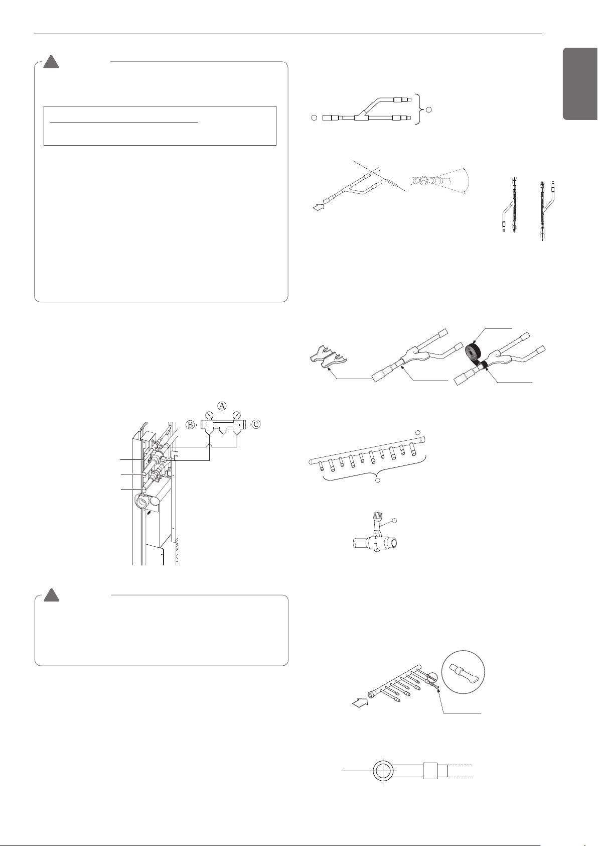
Low Pressure Gas pipe
High Pressure Gas pipe
Liquid pipe
Ⓐ Manifold Gauge
Ⓑ Low pressure side Handle
Ⓒ High pressure side Handle
WARNING
• Pipe to be vacuumed : gas pipe, liquid pipe
• If the refrigerant amount is not exact, it may not operate
properly.
• If additionally bottled refrigerant amount is over 10%, condenser
burst or insufficient indoor unit performance may be caused.
!
Refrigerant charging
WARNING
• Regulation for refrigerant leakage
: the amount of refrigerant leakage should satisfy the following
equation for human safety.
If the above equation can not be satisfied, then follow the follow-
ing steps.
• Selection of air conditioning system: select one of the next
- Installation of effective opening part
- Reconfirmation of Outdoor Unit capacity and piping length
- Reduction of the amount of refrigerant
- Installation of 2 or more security device (alarm for gas leakage)
• Change Indoor Unit type
:
installation position should be over 2m(6.56ft) from the floor (Wall
mounted type Cassette type)
• Adoption of ventilation system
: choose ordinary ventilation system or building ventilation sys-
tem
• Limitation in piping work
: Prepare for earthquake and thermal stress
!
Volume of the room at which Indoor Unit of
the least capacity is installed
Total amount of refrigerant in the system
0.44(kg/m
3
(0.028(lbs/ft
3
))
• When the number of indoor units to be connected to the branch
pipes is less than the number of branch pipes available for connec-
tion then cap pipes should be fitted to the surplus branches.
• Fit branch pipe lie in a horizontal plane.
Pinched pipe
B
Horizontal plane
View from point B in the direction of the arrow
Y branch
Header
A
B
Facing
upwards
Facing
downwards
Within ±3° Within ±3°
Viewed from point A
in direction of arrow
Horizontal
plane
Within ±10°
A
Insulator
(included with kit)
Liquid and gas
pipe joints
Insulator for
field piping
Tape
(field supply)
A
B
C
Ⓐ To Branch Piping or Indoor Unit
Ⓑ To Outside Unit
• Ensure that the branch pipes are attached horizontally or vertically
(see the diagram below.)
• There is no limitation on the joint mounting configuration.
• If the diameter of the refrigerant piping selected by the procedures
described is different from the size of the joint, the connecting sec-
tion should be cut with a pipe cutter.
• Branch pipe should be insulated with the insulator in each kit.
Ⓐ To Outside Unit
Ⓑ To Indoor Unit
• The indoor unit having larger ca-
pacity must be installed closer
to Ⓐ than smaller one.
• If the diameter of the refrigerant
piping selected by the proce-
dures described is different
from the size of the joint, the
connecting section should be
cut with a pipe cutter.
ⓒ Pipe cutter
• When the number of pipes to be
connected is smaller than the
number of header branches, in-
stall a cap to the unconnected
branches.
Branch pipe Fitting
Loading ...
Loading ...
Loading ...