INSTALLATION GUIDE

READ AND SAVE THESE INSTRUCTIONS
Page 23Page 16Page 6
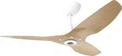
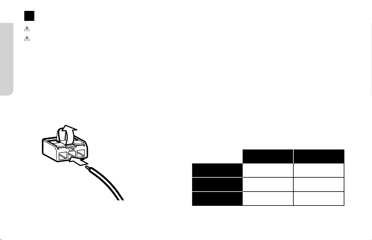
Follow the instructions for your mount type. Each mount uses dierent parts and hardware.
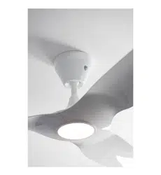
Low Profile Mount
Mounting
Flat ceilings as low as 8 feet
(2.4meters)
Input Voltage
100–240 VAC, 50–60 Hz
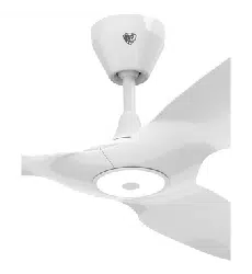
Standard Mount
Mounting
Flat ceilings from 8.5 to 11 feet
(2.5 to 3.4 meters)
Input Voltage
100–240 VAC, 50–60 Hz
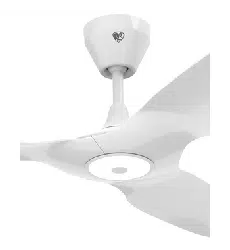
Universal Mount
Mounting
Sloped or flat ceilings from 11 to 18feet
(3.4 to 5.5 meters)
Input Voltage
100–240 VAC, 50–60 Hz
1
HAIKU® BY BIG ASS FANS
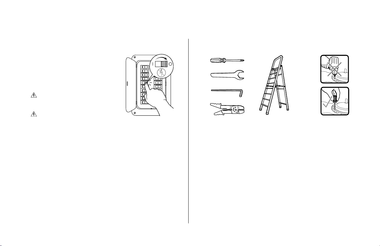
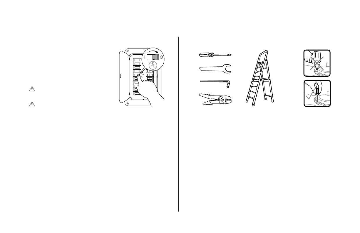
☑ Gather Tools
☑ Select Extension Tube (Universal Mount Only)
If your fan uses the universal mount, you will need to select
the appropriate extension tube for your ceiling height and
slope.
See page 4 for a guide to select the most appropriate
extension tube.
BEFORE YOU START
☑ Turn O Power
Contact a licensed electrician
if you are uncomfortable
performing electrical work. A
licensed electrician must install
the fan if required by local code.
Do not use the fan with a
dimmer switch.
Turn o power at breaker!
☑ Prepare Fan Site
Outlet Box: Make sure your outlet box is suitable for fan
support. If there is not an outlet box at the fan location,
install one on a ceiling joist or beam.
Concrete Ceiling: Install an anchor hook for the safety
cable if required by your local building and safety code.
See the following page for installation details.
Wood Ceiling Joist: Attach the mounting plate or mounting
bracket directly to the joist using two wood screws (not
supplied). Big Ass Fans recommends using corrosion-
resistant 12-11 x 45 mm hex head timber screws with seal.
2
REV. D | © 2018 BIG ASS FANS | ALL RIGHTS RESERVED
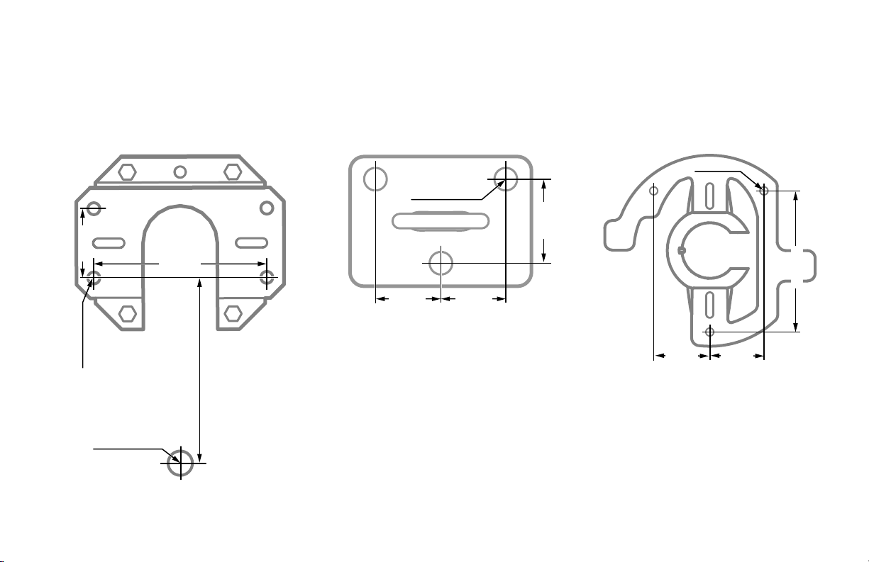
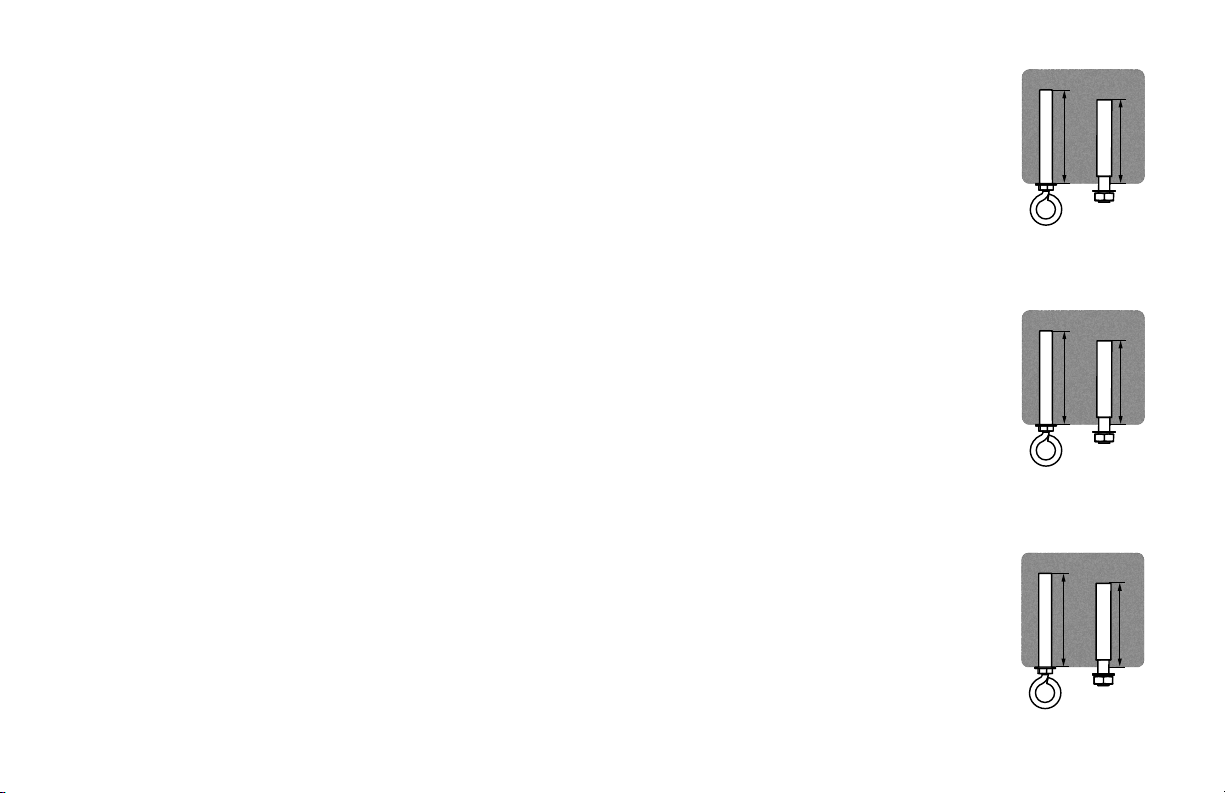
Ø 6 mm
112 mm
45 mm 43 mm
40 mm
Ø 8 mm
(anchor bolt)
Ø 14 mm
(anchor hook)
80 mm
100 mm
Ø 12–12.5 mm
45 mm
35 mm 35 mm
Standard Mount Universal MountLow Profile Mount
Concrete Ceiling
Install an anchor hook for the safety cable if required by your local building and safety code.
3
HAIKU® BY BIG ASS FANS
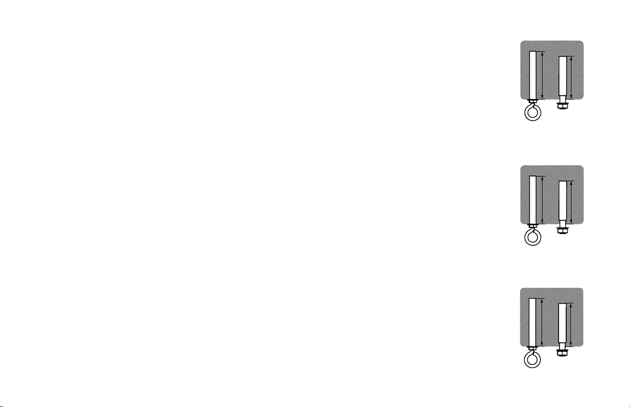
50 mm max
40 mm max
35–40 mm
35–40 mm
50 mm max
40 mm max
Low Profile Mount
Drill four Ø 8 mm holes in the pattern shown. The hole depth should not exceed 40 mm. Remove any dust
from the holes. Insert four anchor bolts into the holes. Strike the heads of the anchor bolts with a hammer,
ensuring the bolt sleeves are flush with the ceiling surface. Position the mounting plate on the anchor bolts.
Ensure all four anchor bolts are fully tightened to expand and lock the anchors.
If required by local building and safety codes, install an anchor hook for the safety cable. Drill a Ø 14 mm
hole for the anchor hook in the pattern shown. The hole depth should not exceed 50 mm. Remove any dust
from the hole, and then insert the anchor hook and fully tighten.
Standard Mount
Drill three Ø 12–12.5 mm holes in the pattern shown. The hole depth should not exceed 35–40 mm.
Remove any dust from the holes. Insert three anchor bolts into the holes. Strike the heads of the anchor
bolts with a hammer, ensuring the bolt sleeves are flush with the ceiling surface. Position the hanger plate
on the anchor bolts. Ensure all three anchor bolts are fully tightened to expand and lock the anchors.
If required by local building and safety codes, install an anchor hook for the safety cable. Drill a
Ø8–8.5mm hole for the anchor hook adjacent to the hanger plate. The hole depth should not exceed
35–40mm. Remove any dust from the hole, and then insert the anchor hook and fully tighten.
Universal Mount
Drill three Ø 6 mm holes in the pattern shown. The hole depth should not exceed 40 mm. Remove any dust
from the holes. Insert three anchor bolts into the holes. Strike the heads of the anchor bolts with a hammer,
ensuring the bolt sleeves are flush with the ceiling surface. Position the mounting bracket on the anchor
bolts. Ensure all three anchor bolts are fully tightened to expand and lock the anchors.
If required by local building and safety codes, install an anchor hook for the safety cable. Drill a Ø 8 mm
hole for the anchor hook. The hole depth should not exceed 50 mm. Remove any dust from the hole, and
then insert the anchor hook and fully tighten.

4
REV. D | © 2018 BIG ASS FANS | ALL RIGHTS RESERVED
Choosing an Extension Tube (Universal Mount Only)
Consult the tables below to select the appropriate extension tube for your fan.
Ceiling Slope
Haiku fans with a universal mount can be installed on sloped
ceilings with an angle no greater than 33°.
Fan Diameter
Maximum
Ceiling Slope
Extension Tube
Length
52 in.
(1.3 m)
26°
20 in.
(508 mm)
52 in.
(1.3 m)
33°
32 in.
(813 mm)
60 in.
(1.5 m)
22°
20 in.
(508 mm)
60 in.
(1.5 m)
33°
32 in.
(813 mm)
84 in.
(2.1 m)
16°
20 in.
(508 mm)
84 in.
(2.1 m)
29°
32 in.
(813 mm)
If installing your fan outdoors on a sloped ceiling, Big
Ass Fans recommends installing the Sloped Ceiling Fan
Stabilizer kit (available separately).
Ceiling Height
For optimum performance, Big Ass Fans recommends the
following extension tube lengths based on ceiling height.
Ceiling Height Extension Tube Length
9.5–11 ft
(2.9–3.4 m)
20 in.
(508 mm)
11–13 ft
(3.4–4 m)
32 in.
(813 mm)
13–14 ft *
(4–4.3 m) *
48 in. *
(1219 mm) *
>14 ft *
(>4.3 m) *
60 in. *
(1524 mm) *
* Big Ass Fans recommends using an extended length
extension tube for ceiling heights over 13 ft (4 m). The fan
comes standard with 20 in. (508 mm) and 32 in. (813 mm)
extension tubes. Other lengths are available by contacting
Customer Service.

Universal Mount
6
REV. D | © 2018 BIG ASS FANS | ALL RIGHTS RESERVED
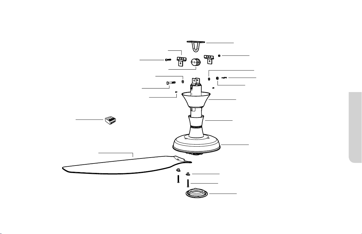
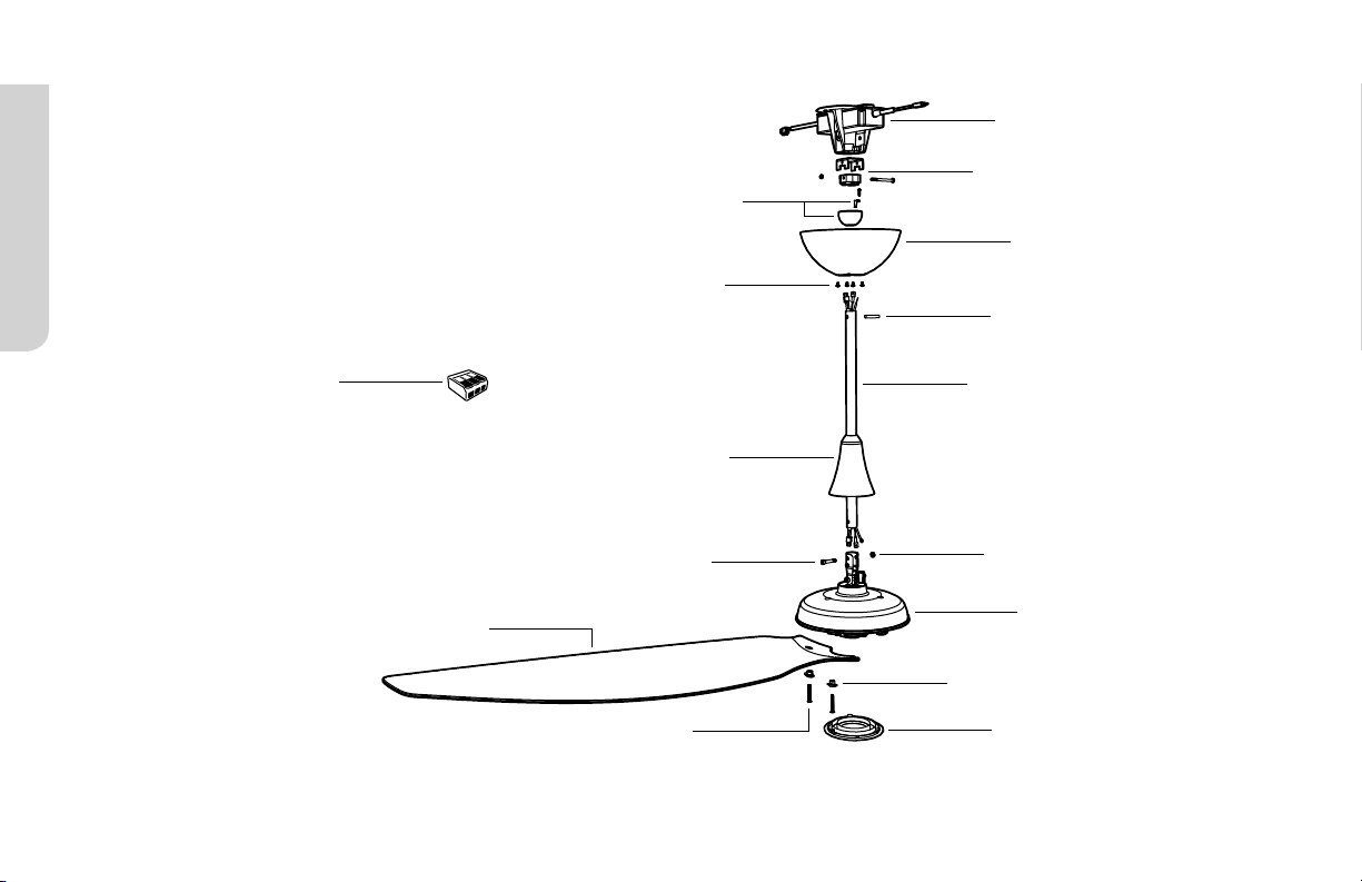
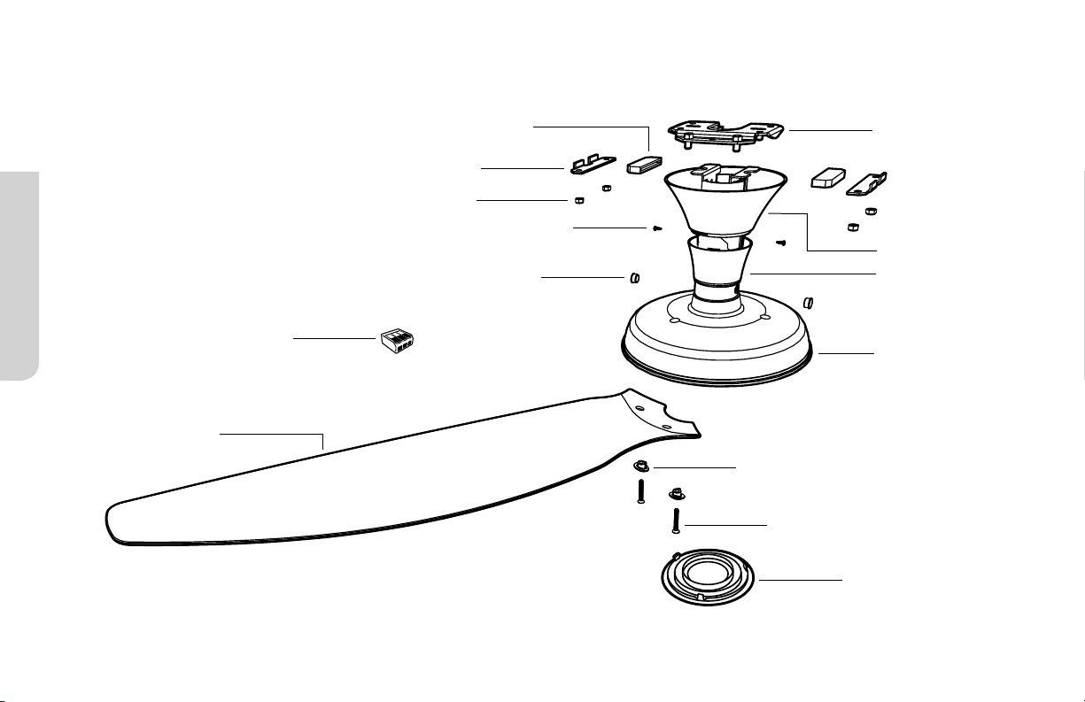
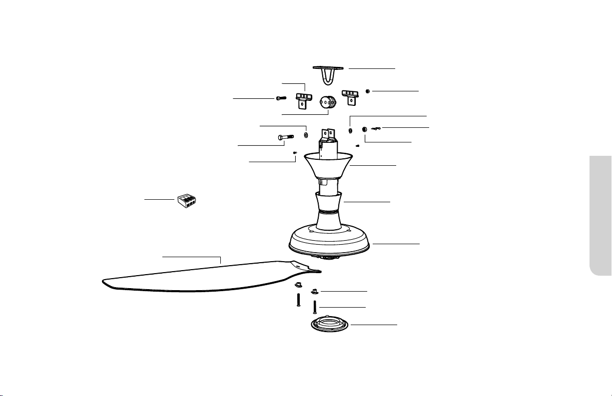
UNIVERSAL MOUNT
Mounting Bracket
Canopy
Extension Tube
Lower Cover
M5 Screws (6)
Canopy Screws (4)
Wiring Cover
Airfoils (3)
M6 Nut
M6 x 32 mm Bolt
Fan Stabilizer Kit
(Flat ceilings only)
Grommets (6)
Mounting Ball
and Wedge
Motor Hub
Wire Connectors
6 mm Steel Pin
Safety cable not shown
If the EMI filter is included, install it with your fan.
For sloped ceilings, Big Ass Fans recommends installing the Sloped Ceiling Fan Stabilizer Kit (available separately).
Universal Mount
7
HAIKU® BY BIG ASS FANS
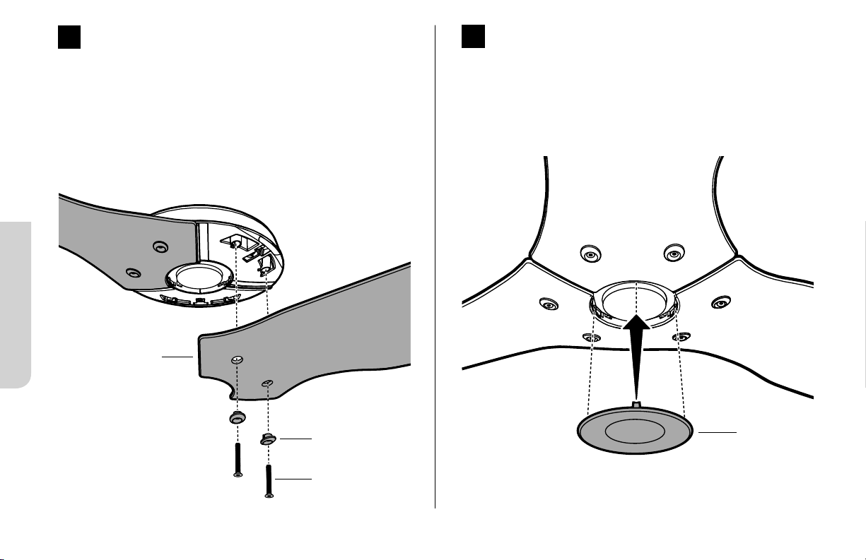
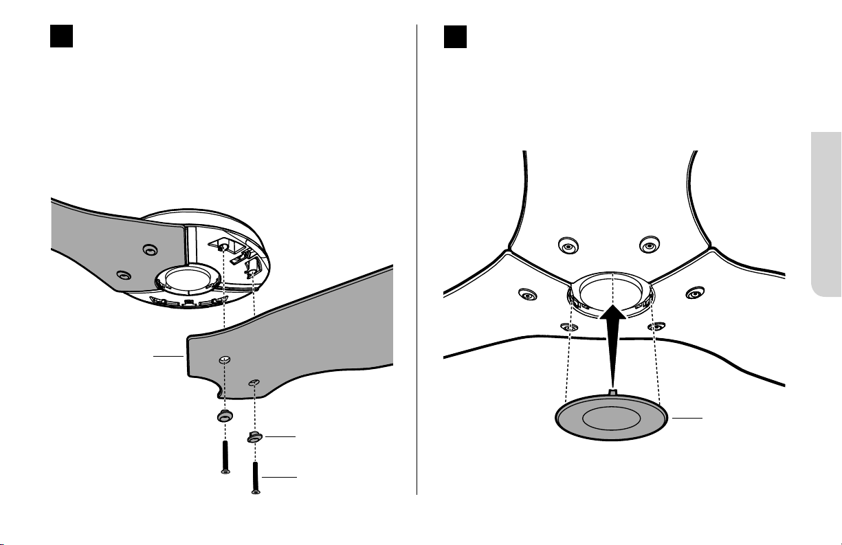
Install Airfoils
Moving clockwise, align each airfoil on the fan hub and secure
it with the airfoil hardware (Fig. 1). Make sure the sticker color
on each airfoil matches the corresponding sticker color on
the fan hub!
M5 Screw
Grommet
1
Fig. 1
Airfoil
2
Install Lower Cover
Attach the lower cover as shown (Fig. 2).
Lower Cover
Fig. 2
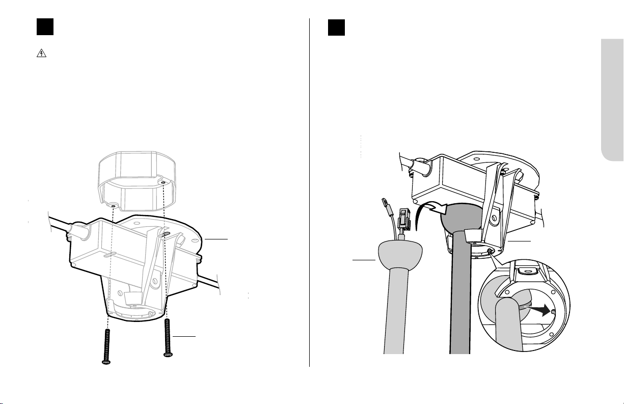
Fig. 7
Mounting
Bracket
Mounting
Ball
Universal Mount
11
HAIKU® BY BIG ASS FANS
7
Hang Fan
Raise the fan to the mounting bracket. Align the rib in the
mounting bracket with the slot in the mounting ball, position the
mounting ball, and let the fan hang freely (Fig. 7).
Gently twist the extension tube to ensure it is properly seated
and will not move during fan operation.
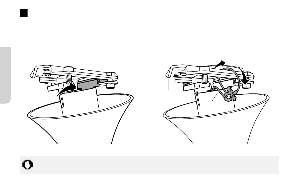
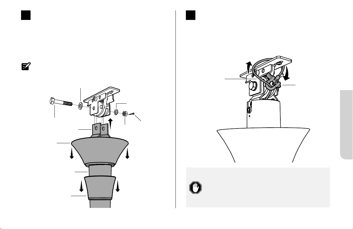
Install Mounting Bracket
Disconnect power to the fan location before installing
the mounting bracket!
Secure the mounting bracket to the mounting structure with
suitable hardware (Fig. 6).
Outlet box shown. Your mounting structure may dier from
the illustration.
6
Fig. 6
Suitable Mounting
Hardware
Mounting
Bracket

Universal Mount
12
REV. D | © 2018 BIG ASS FANS | ALL RIGHTS RESERVED
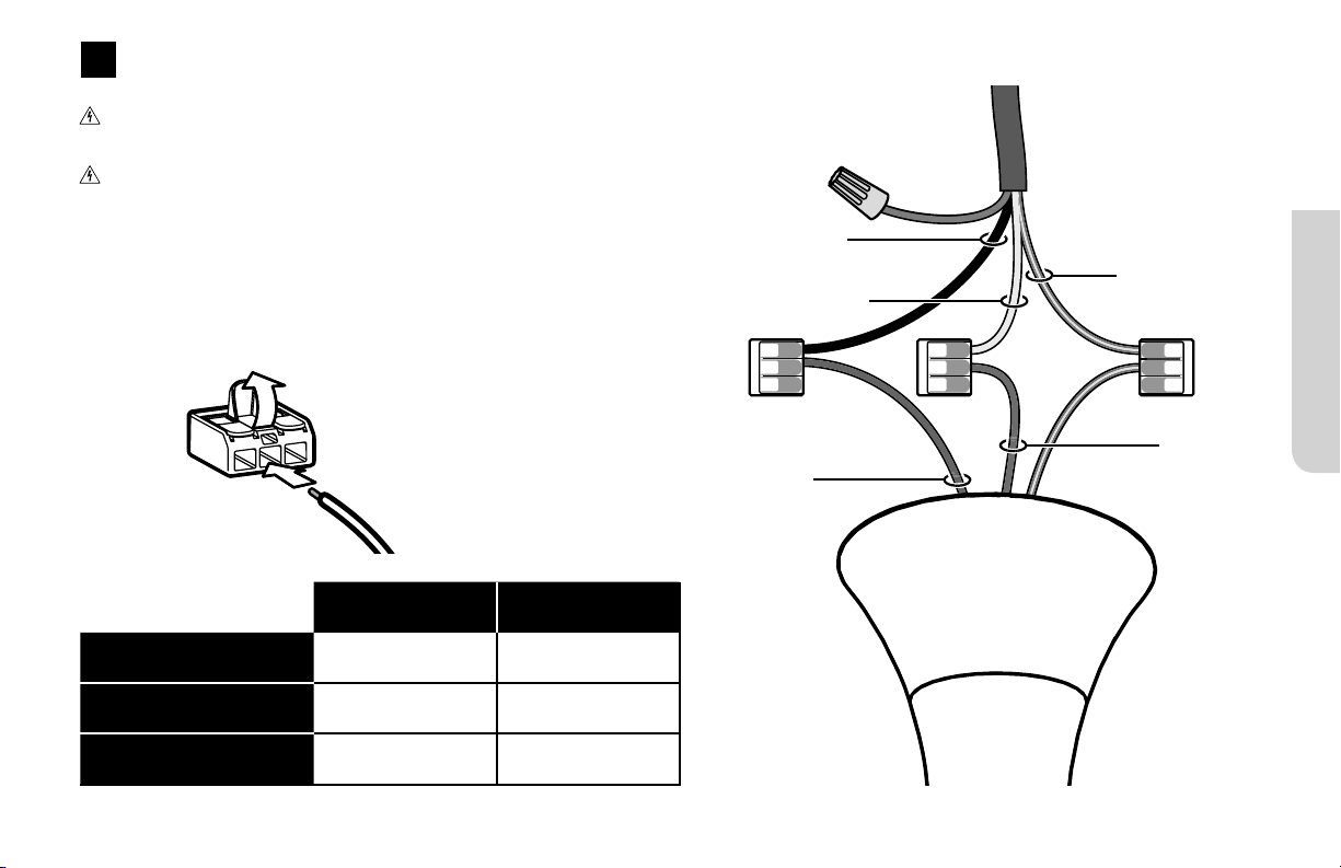
Wire the Fan
Disconnect power to the fan location before wiring the fan!
Do not connect the fan to a damaged power source! Do not attempt to resolve electrical failures on your own. Consult a
qualified electrician if uncertain of the electrical installation of this fan.
Wire the fan as shown in the diagram using the wire connectors (Fig. 8). If your fan packaging included an EMI filter, install it as shown.
Attach the green ground wire to the mount with the unpainted screw. Connect the wiring harness from the power supply to the wiring
harness from the extension tube, making sure that the wiring and safety cable are routed in the same direction.
8
North America
100–120 V
All other regions
AC Hot/L1
Brown
Black Brown
AC Neutral/L2
Blue
White Blue
PE/Earth Ground
Green with Yellow
Green or Bare
Copper
Green with Yellow
Fig. 8

Universal Mount
13
HAIKU® BY BIG ASS FANS
Wiring Diagram
(No EMI Filter)
WHITE
BLACK
BROWN
BLUE
WHITE
BLACK
BROWN
BLUE
EMI FILTER
Wiring Diagram
(With EMI Filter)
GREEN &
YELLOW
GREEN &
YELLOW
Universal Mount
14
REV. D | © 2018 BIG ASS FANS | ALL RIGHTS RESERVED
Install Flat Ceiling Fan Stabilizer
If installing your fan on a sloped ceiling, Big Ass Fans recommends installing the Sloped Ceiling Fan Stabilizer kit.
Fit the stabilizer block into the notches on top of the mounting ball (Fig. 9.1).
Secure the stabilizer plate to the stabilizer block with the M6 x 70 mm bolt and M6 nut (Fig. 9.2).
Fig. 9.1 Fig. 9.2
9
Stabilizer Block
Mounting Ball
Stabilizer Plate
M6 x 70 mm Bolt
M6 Nut
Universal Mount
15
HAIKU® BY BIG ASS FANS
11
Raise Canopy
Raise the canopy to the mounting bracket, aligning the four
holes on the canopy with the holes on the bracket. Secure
the canopy to the mounting bracket with the painted screws
(Fig.11). Make sure all wires and the safety cable are tucked in
the canopy.
10
Secure Safety Cable
Loop the safety cable around the mounting bracket or building
structure, and then secure it with the shackle (Fig. 10).
Canada: The safety cable must be secured directly
to an existing part of the building structure. It
may be necessary to install additional structural
material to provide attachment points.
Safety Cable
Shackle
Canopy
Canopy
Screw
Fig. 10
Fig. 11
Congratulations!
Installation is now complete. Test your fan using the remote
control.

Low Profile Mount
REV. D | © 2018 BIG ASS FANS | ALL RIGHTS RESERVED
16
LOW PROFILE MOUNT
Use the extension tube screw caps that match the color of your fan.
Safety cable not shown.
Mounting Plate
Rubber Bumpers (2)
Mounting Brackets (2)
6 mm Nylock Nuts (4)
Extension Tube Screw Caps (2)
Lower Cover
Grommets (6)
M5 Screws (6)
Motor Hub
Wiring Cover Screws (2)
Airfoils (3)
Wire Connectors
Wiring Cover
Wiring Cover Trim
Low Profile Mount
HAIKU® BY BIG ASS FANS
17
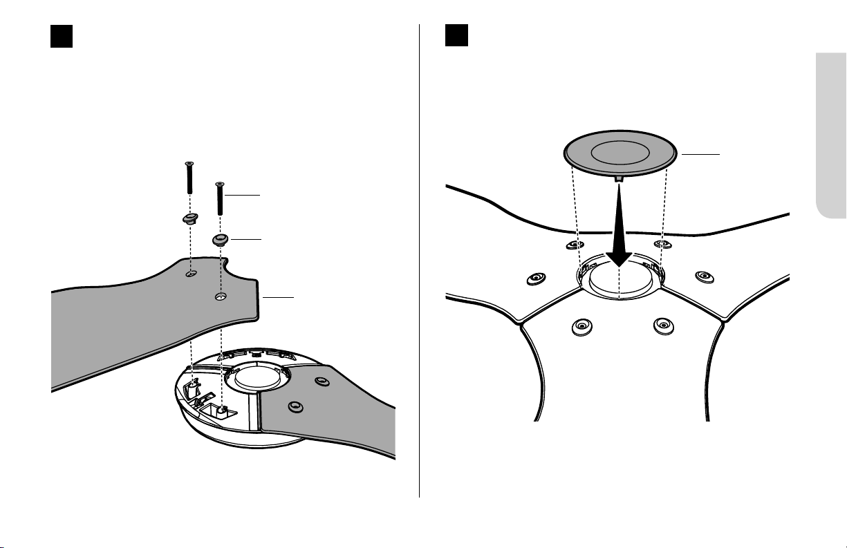
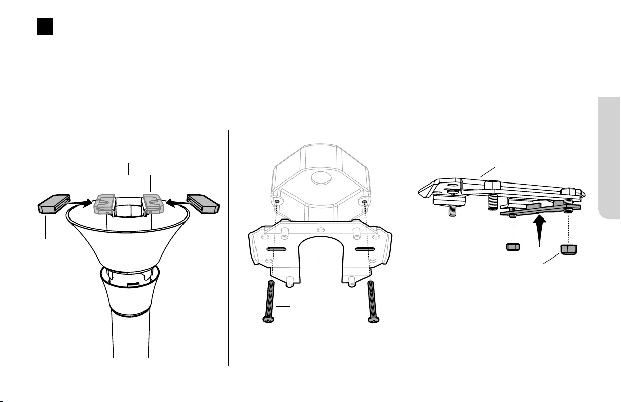
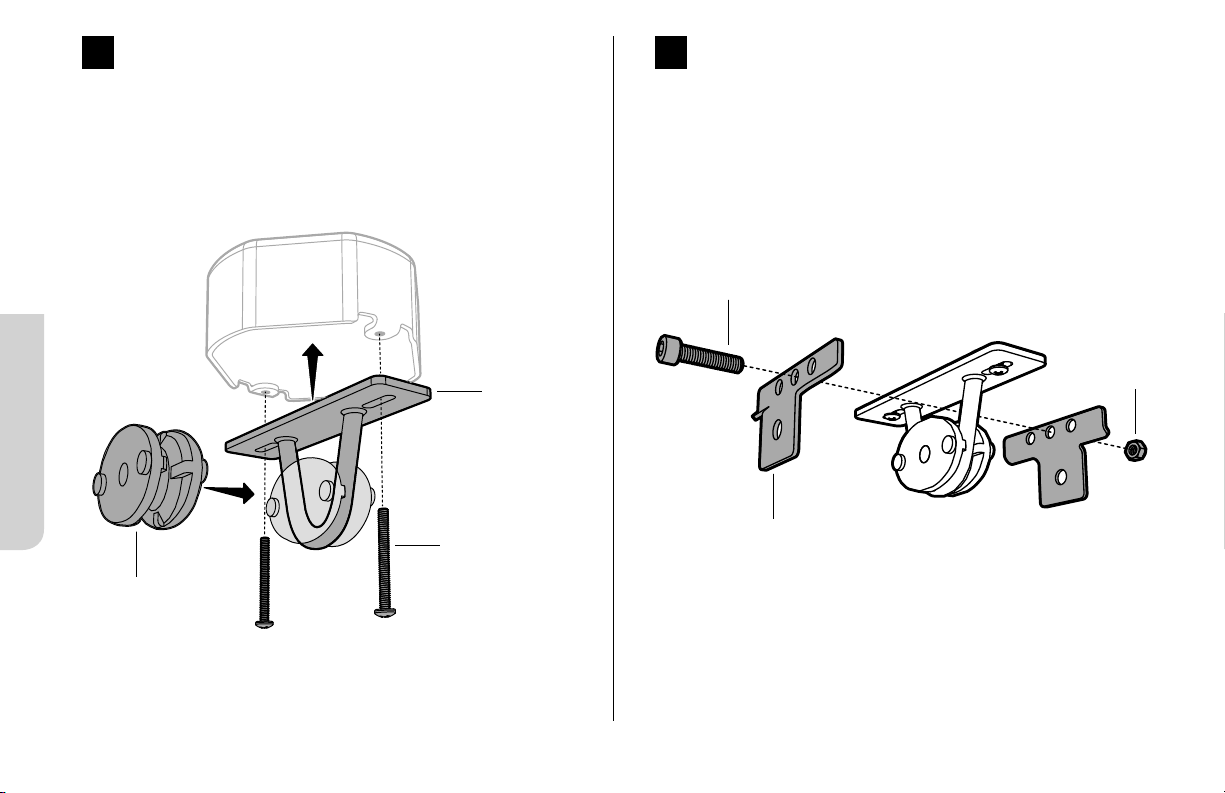
Install Mounting Plate and Single Bracket
Slide the rubber bumpers onto the extension tube brackets (Fig. 1.1).
Secure the mounting bracket to the mounting structure with suitable hardware (Fig. 1.2). Your mounting structure may dier from the
illustration.
Loosely attach one mounting bracket to the mounting plate with two 6 mm nylock nuts, but do not fully tighten (Fig. 1.3).
1
Fig. 1.1 Fig. 1.2 Fig. 1.3
Rubber
Bumper
Extension Tube Brackets
Mounting
Plate
6 mm Nylock Nut
Mounting Plate
Suitable Mounting
Hardware
Outlet box shown. Your mounting
structure may dier from the illustration.
Low Profile Mount
REV. D | © 2018 BIG ASS FANS | ALL RIGHTS RESERVED
18
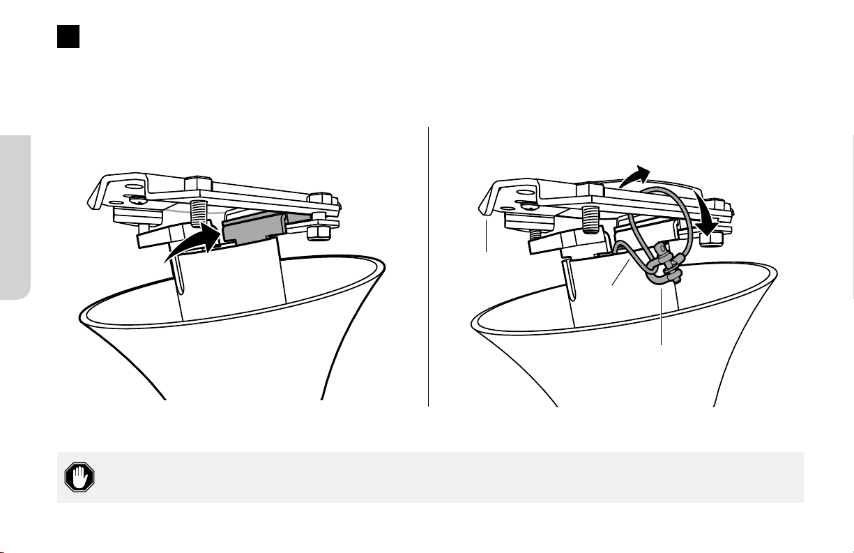
Secure Safety Cable
Raise the fan to the bracket and temporarily rest one rubber bumper in the space between the bracket and plate (Fig. 2.1). While
supporting the fan, loop the safety cable around the mounting plate or building structure, and then secure it with the shackle (Fig.2.2).
2
Canada: The safety cable must be secured directly to an existing part of the building structure. It may be necessary to
install additional structural material to provide attachment points.
Mounting
Plate
Safety
Cable
Shackle
Fig. 2.2
Fig. 2.1
Low Profile Mount
HAIKU® BY BIG ASS FANS
21
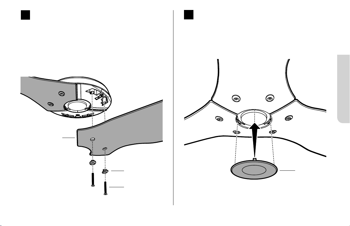
Install Airfoils
Moving clockwise, align each airfoil on the fan hub and secure
it with the airfoil hardware (Fig. 6). Make sure the sticker color
on each airfoil matches the corresponding sticker color on
the fan hub!
M5 Screw
Grommet
6
Fig. 6
Airfoil
7
Install Lower Cover
Attach the lower cover as shown (Fig. 7).
Lower Cover
Fig. 7
Low Profile Mount
REV. D | © 2018 BIG ASS FANS | ALL RIGHTS RESERVED
22
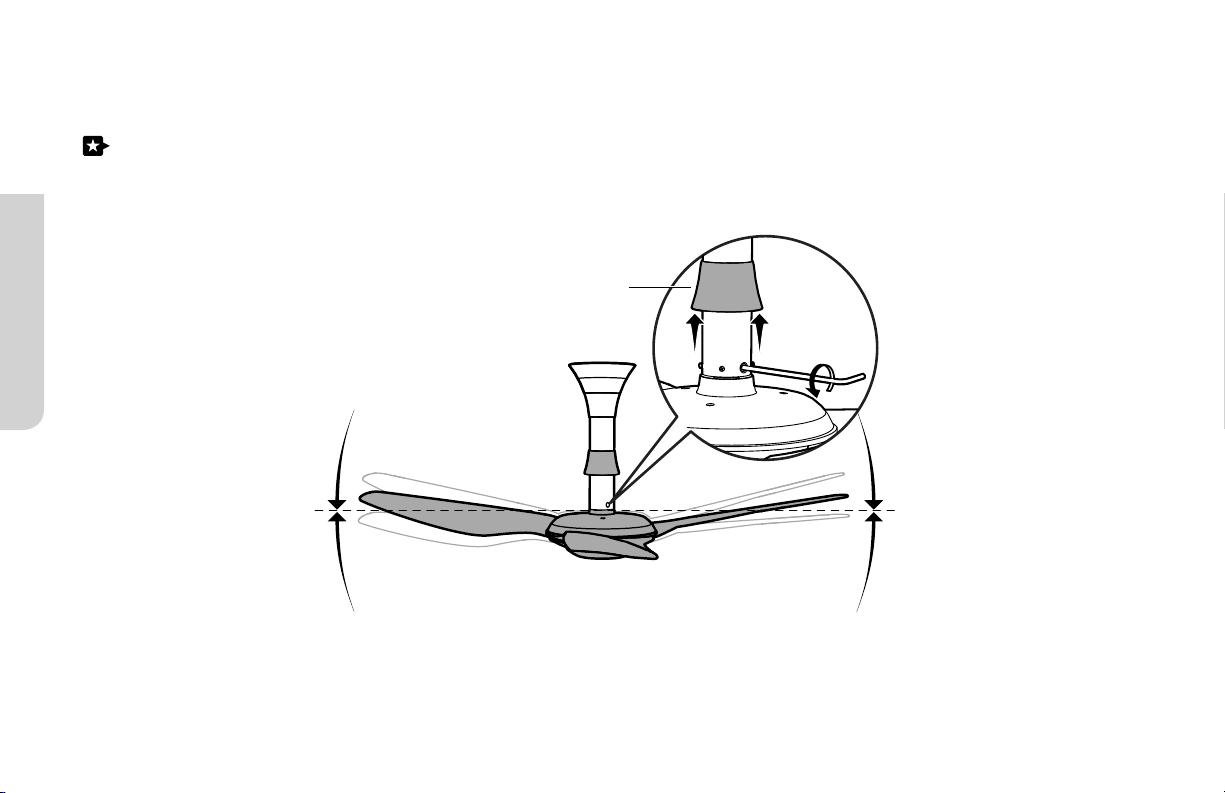
Congratulations!
Installation is now complete. Test your fan using the remote control.
If your fan appears slightly tilted, raise the lower motor cover trim and locate the pivot bolt. Loosen the bolt with a 5 mm hex key
to allow the fan to hang straight, and then re-tighten.
Lower Motor Cover Trim
Standard Mount
HAIKU® BY BIG ASS FANS
23
Use the extension tube screw caps that match the color of your fan.
Safety cable not shown.
Mounting Bracket
Wiring Cover
Lower Cover
Motor Hub
STANDARD MOUNT
Rubber Bushing
Wiring Cover Trim
Grommets (6)
Wiring Cover Screws
2 mm x 2 mm Split Pin
Mounting Brace Brackets (2)
M8 Bolt
M6 x 25 mm Screw
M8 Nut
8 mm Lock Washer
M6 Nut
Airfoils (3)
Wire Connectors
8 mm Flat Washer
M5 Screws (6)

Standard Mount
REV. D | © 2018 BIG ASS FANS | ALL RIGHTS RESERVED
26
5
Wire Fan
Disconnect power to the fan location before wiring the fan!
Do not connect the fan to a damaged power source! Do not
attempt to resolve electrical failures on your own. Consult a
qualified electrician if uncertain of the electrical installation of
this fan.
Wire the fan as shown in the diagram using the wire connectors (Fig. 5).
Wiring Diagram
BLUE
BROWN
WHITE
BLACK
GREEN &
YELLOW
North America
100–120 V
All other regions
AC Hot/L1
Brown
Black Brown
AC Neutral/L2
Blue
White Blue
PE/Earth Ground
Green with Yellow
Green or Bare
Copper
Green with Yellow
Fig. 5
Standard Mount
REV. D | © 2018 BIG ASS FANS | ALL RIGHTS RESERVED
28
Install Airfoils
Moving clockwise, align each airfoil on the fan hub and secure
it with the airfoil hardware (Fig. 7). Make sure the sticker color
on each airfoil matches the corresponding sticker color on
the fan hub!
M5 Screw
Grommet
7
Fig. 7
Airfoil
8
Install Lower Cover
Attach the lower cover as shown (Fig. 8).
Lower Cover
Fig. 8
30
REV. D | © 2018 BIG ASS FANS | ALL RIGHTS RESERVED
TROUBLESHOOTING
Your fan may occasionally jerk forward and backward upon startup. This is normal and does not aect fan operation.
Try these troubleshooting steps before contacting Customer Service. For additional operation, maintenance, and troubleshooting
information, visit bigassfans.com/support
Issue Solution
The fan will not start.
• Make sure the fan is receiving power.
• Check your circuit breaker or fuse panel and wall switch for functionality.
• Make sure the fan is properly wired and grounded.
• Make sure the plastic film in the remote's battery tray has been removed.
The fan wobbles.
Remove the airfoils and make sure the colored dot sticker on each airfoil matches the
corresponding sticker on the motor hub. If the stickers do not match, move the airfoils
to the matching attachment points.
The fan appears slightly tilted.
(Low profile and standard mounts only.)
Raise the lower motor cover trim and locate the pivot bolt. Loosen the bolt with a 5 mm
hex key to allow the fan to hang straight, and then re-tighten.
The fan is noisy during operation.
Bring the fan to a complete stop.
• Gently turn the airfoils by hand, making sure there are no fan parts rubbing on the
motor hub when the fan rotates.
• Check all mounting and fan hardware. If loose, tighten.
I need to reboot the fan.
Press and hold the On/O button until the LED indicators start blinking.
Within three seconds of the LEDs flashing, press the On/O button again. When the
LEDs stop blinking, the reboot is complete.
1
HAIKU® BY BIG ASS FANS
AVANT DE COMMENCER
☑ Coupez le courant
Contactez un électricien
professionnel si vous ne vous
sentez pas à l’aise avec les travaux
électriques. La règlementation
locale peut exiger que le ventilateur
soit installé par un professionnel.
N’utilisez pas de variateur
d’intensité avec ce ventilateur.
Coupez le courant au niveau du
disjoncteur!
☑ Préparation du site de montage
Boîte de dérivation : Vérifiez que votre boîte de dérivation
peut supporter le poids et le ballant d’un ventilateur. S’il n’y
a pas de boîte de dérivation à l’emplacement du ventilateur,
installez-en une sur une solive ou sur une poutre.
Plafond en béton : Si les normes de sécurité et de
construction en vigueur l’exigent, installez un crochet
d’ancrage pour l’élingue de sécurité.
Solive de plafond en bois : Fixez directement la plaque ou
le support de fixation à la solive au moyen de deux vis à
bois (non fournies). Big Ass Fans recommande l’utilisation
de vis à bois à tête hexagonale de 12–11 × 45 mm
résistantes à la corrosion, freinées.
☑ Préparez les outils nécessaires
☑ Choisissez une tige de prolongation (fixation
universelle uniquement)
Si vous utilisez la fixation universelle, vous devez choisir
une tige de prolongation adaptée à la hauteur et à la pente
de votre plafond.
Tournez à la page 4 pour savoir comment choisir la tige de
prolongation la mieux adaptée à votre installation.

2
RÉV.D | © 2018 BIG ASS FANS | TOUS DROITS RÉSERVÉS
Plafond en béton
Si les normes de sécurité et de construction en vigueur l’exigent, installez un crochet d’ancrage pour l’élingue de sécurité.
Ø 6 mm
112 mm
45 mm 43 mm
40 mm
Ø 8 mm
(boulon d’ancrage)
Ø 14 mm
(crochet d’ancrage)
80 mm
100 mm
Ø 12–12,5 mm
45 mm
35 mm 35 mm
Fixation standard Fixation universelleFixation courte

3
HAIKU® BY BIG ASS FANS
Fixation courte
Percez quatre trous de Ø 8 mm tel qu’illustré ci-contre. La profondeur des trous ne doit pas excéder 40 mm.
Époussetez les trous. Insérez quatre boulons d’ancrage dans les trous. À l’aide d’un marteau, frappez la tête des
boulons d’ancrage de sorte que la cheville aeure à la surface du plafond. Positionnez la plaque de fixation sur les
boulons d’ancrage. Assurez-vous que les quatre boulons d’ancrage sont serrés à fond pour expanser et verrouiller
les systèmes d’ancrage.
Si les normes de sécurité et de construction en vigueur l’exigent, installez un crochet d’ancrage pour l’élingue de
sécurité. Percez un trou de Ø 14 mm pour le crochet d’ancrage, tel qu’illustré ci-contre. La profondeur du trou ne doit
pas excéder 50 mm. Époussetez le trou, insérez le crochet d’ancrage et serrez à fond.
Fixation standard
Percez trois trous de Ø 12–12,5 mm tel qu’illustré ci-contre. La profondeur des trous ne doit pas excéder 35–40
mm. Époussetez les trous. Insérez trois boulons d’ancrage dans les trous. À l’aide d’un marteau, frappez la tête des
boulons d’ancrage de sorte que la cheville aeure à la surface du plafond. Positionnez la plaque de suspension sur
les boulons d’ancrage. Assurezvous que les trois boulons d’ancrage sont serrés à fond pour expanser et verrouiller
les systèmes d’ancrage.
Si les normes de sécurité et de construction en vigueur l’exigent, installez un crochet d’ancrage pour l’élingue de
sécurité. Percez un trou de Ø 8–8,5 mm pour le crochet d’ancrage à côté de la plaque de suspension. La profondeur
du trou ne doit pas excéder 35–40 mm. Époussetez le trou, insérez le crochet d’ancrage et serrez à fond.
Fixation universelle
Percez trois trous de Ø 6 mm tel qu’illustré ci-contre. La profondeur des trous ne doit pas excéder 40 mm.
Époussetez les trous. Insérez trois boulons d’ancrage dans les trous. À l’aide d’un marteau, frappez la tête des
boulons d’ancrage de sorte que la cheville aeure à la surface du plafond. Positionnez le support de fixation sur les
boulons d’ancrage. Assurez-vous que les trois boulons d’ancrage sont serrés à fond pour expanser et verrouiller les
systèmes d’ancrage.
Si les normes de sécurité et de construction en vigueur l’exigent, installez un crochet d’ancrage pour l’élingue de
sécurité. Percez un trou de Ø 8 mm pour le crochet d’ancrage. La profondeur du trou ne doit pas excéder 50 mm.
Époussetez le trou, insérez le crochet d’ancrage et serrez à fond.
50 mm max.
40 mm max.
35–40 mm
35–40 mm
50 mm max.
40 mm max.
5
HAIKU® BY BIG ASS FANS
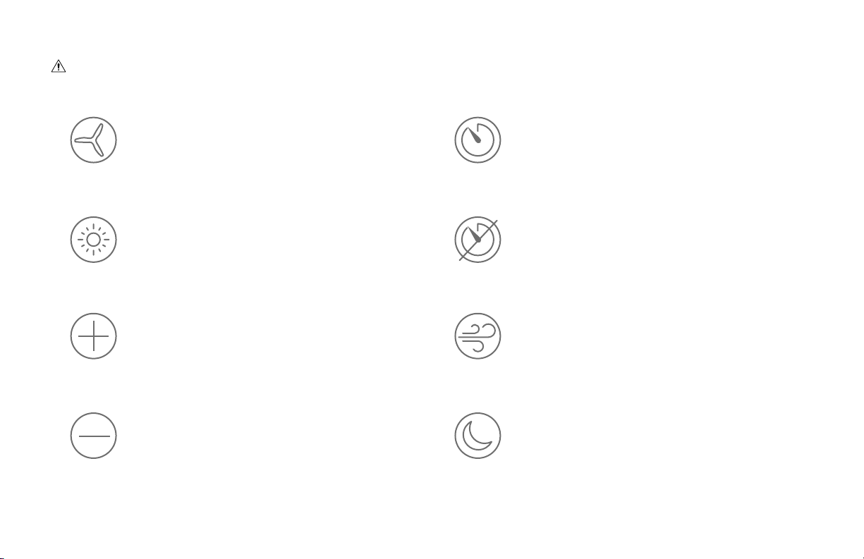
Télécommande Haiku
Conservez la télécommande à l’abri de l’eau et de la pluie.
Allume ou éteint le ventilateur.
Active le minuteur pour une durée maximale de
huit heures. Chaque pression allonge la durée
d’une heure.
Allume ou éteint l’éclairage. Désactive le minuteur.
Augmente la vitesse de rotation ou la
luminosité.
Fait varier la vitesse du ventilateur pour simuler
une brise naturelle.
Réduit la vitesse de rotation ou la
luminosité.
Ajuste automatiquement la vitesse du ventilateur
pendant la nuit, pour un sommeil tout en confort.
Fixation universelle
6
RÉV.D | © 2018 BIG ASS FANS | TOUS DROITS RÉSERVÉS
FIXATION UNIVERSELLE
Élingue de sécurité non représentée.
Si votre ventilateur est livré avec un filtreEMI, installez-le.
Pour les plafonds rampants, Big Ass Fans vous recommande d’utiliser le kit de stabilisation pour plafond rampant (disponible séparément).
Support de fixation
Monture
Tige de prolongation
Cache inférieur
VisM5 (6)
Vis pour monture (4)
Couvre-fils
Pales (3)
ÉcrouM6
Vis M6×32mm
Kit de stabilisation
(plafonds horizontaux uniquement)
Œillets (6)
Cale de montage et
boule de fixation
Moyeu
Connecteurs électriques
Goupille en
acier 6mm

Fixation universelle
8
RÉV.D | © 2018 BIG ASS FANS | TOUS DROITS RÉSERVÉS
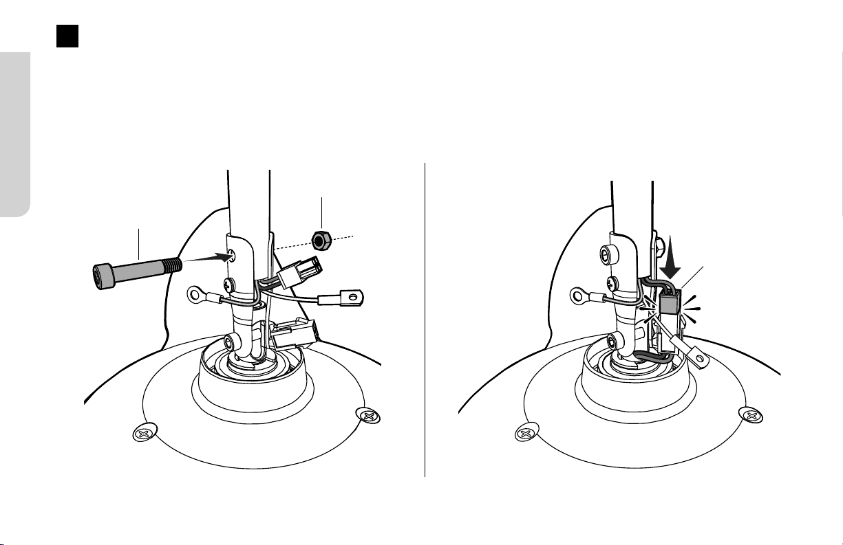
3
Fixation de la tige de prolongation et du faisceau de fils
Alignez les trous de la tige de prolongation sur ceux du support moteur, puis fixez la tige de prolongation à l’aide de la visM6×32mm
et de l’écrouM6 (fig. 3.1).
Branchez le faisceau de fils sortant de la tige de prolongation au connecteur sortant du moyeu (fig.3.2).
Fig. 3.1 Fig. 3.2
Faisceau
de fils
Vis M6×32mm
ÉcrouM6
Fixation universelle
9
HAIKU® BY BIG ASS FANS
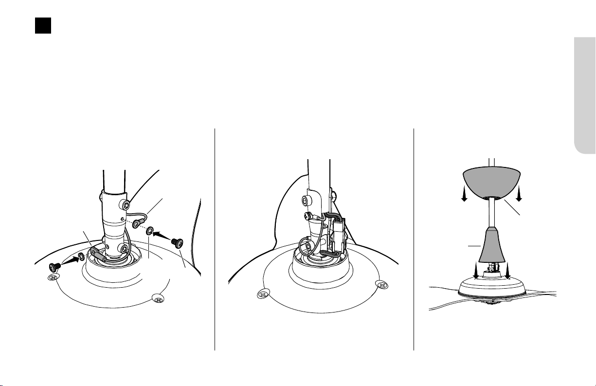
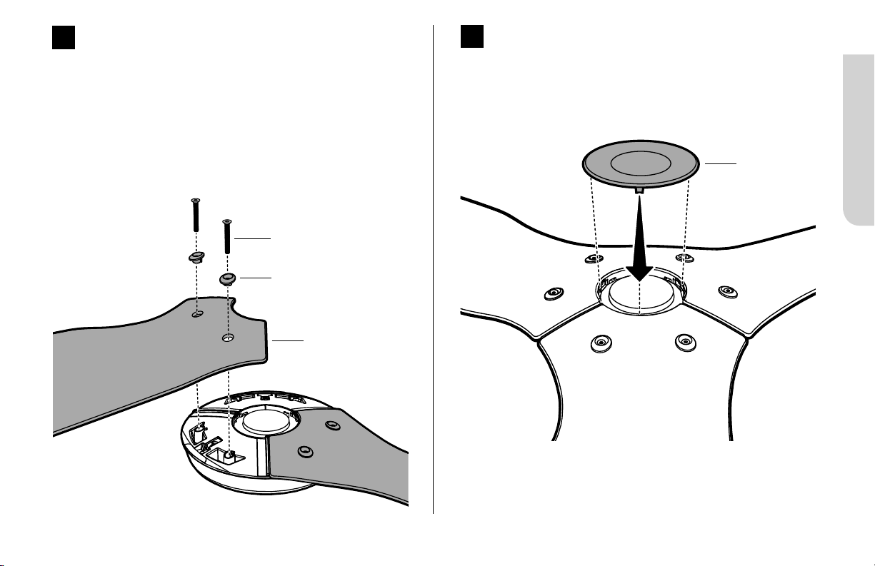
4
Fixation de la partie inférieure de l’élingue de sécurité et du fil de terre
Fixez l’élingue de sécurité et la cosse du fil de terre à l’aide des vis non peintes et des rondelles Grower (fig.4.1).
Vérifiez que la visserie est bien serrée, puis tirez doucement sur les câbles en haut de la tige de prolongation pour éliminer le mou
(fig.4.2).
Faites descendre le couvre-filsle long de la tige de prolongation et laissez-le en appui sur le moyeu du ventilateur. Assurez-vous
qu’aucun fil n’est visible entre le couvre-fils et le moyeu du ventilateur. Faites descendre la monturele long de la tige de prolongation
(fig.4.3).
Fig. 4.1 Fig. 4.2 Fig. 4.3
Couvre-fils
Monture
Élingue de
sécurité
Fil de terre
(vert)
Rondelle
Grower
Vis
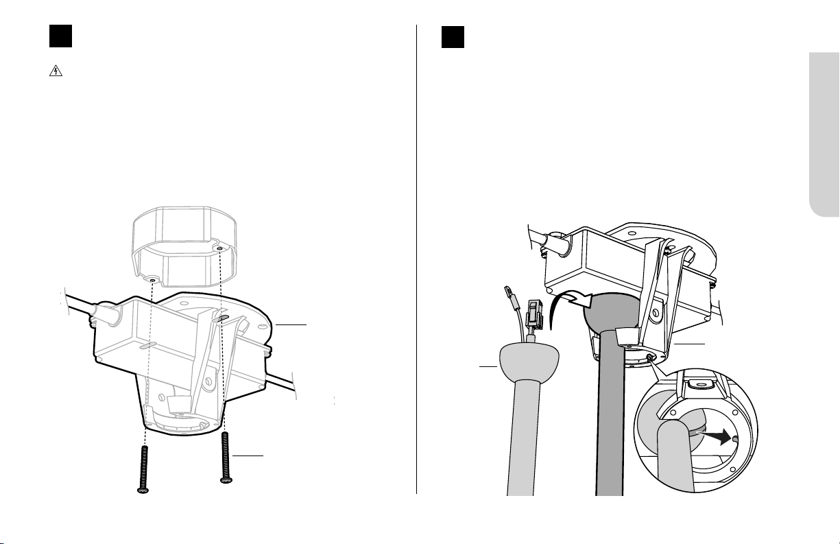
Fig.7
Fixation universelle
11
HAIKU® BY BIG ASS FANS
7
Suspension du ventilateur
Soulevez le ventilateur jusqu’au support de fixation. Alignez
la nervure du support de fixation sur la fente de la boule de
fixation, mettez la boule de fixation en place, puis relâchez le
ventilateur (fig.7).
Faites légèrement pivoter la tige de prolongation pour vous
assurer qu’elle est bien en place et qu’elle ne bougera pas une
fois le ventilateur en marche.
Mise en place du support de fixation
Coupez l’alimentation du ventilateur avant d’installer le
support de fixation!
Fixez le support de fixation à la structure d'ancrage à l’aide des
visserie de montage approprié (Fig. 6).
Boîte de dérivation illustrée. La configuration de votre
structure d’ancrage peut être diérente de celle de
l’illustration.
6
Fig.6
Visserie de
montage approprié
Support de
fixation
Support de
fixation
Boule de
fixation
Fixation universelle
12
RÉV.D | © 2018 BIG ASS FANS | TOUS DROITS RÉSERVÉS
Câblage du ventilateur
Coupez l’alimentation du ventilateur avant de procéder au câblage!
Ne branchez jamais le ventilateur à une source de courant endommagée! N’essayez pas de réparer une panne électrique seul.
Contactez un électricien qualifié si vous avez le moindre doute concernant le raccordement électrique de ce ventilateur.
Procédez au câblage conformément au schéma électrique, en utilisant les connecteurs électriques (fig.8). Si votre ventilateur est livré
avec un filtreEMI, installez-le en suivant le schéma électrique.
Fixez le fil de terre vert au support à l’aide de la vis non peinte. Branchez le faisceau de fils provenant de l’alimentation au faisceau de
fils sortant de la tige de prolongation, en veillant à ce que les fils électriques et l’élingue de sécurité sortent du même côté.
8
Amérique du Nord
100–120V
Autres régions
PhaseCA/L1
Marron
Noir Marron
NeutreCA/L2
Bleu
Blanc Bleu
PE/Terre
Vert et jaune
Vert ou cuivre nu Vert et jaune
Fig.8

Fixation universelle
13
HAIKU® BY BIG ASS FANS
Schéma électrique
(sans filtre EMI)
BLANC
NOIR
MARRON
BLEU
BLANC
NOIR
MARRON
BLEU
FILTRE EMI
Schéma électrique
(avec filtre EMI)
VERT ET
JAUNE
VERT ET
JAUNE

Fixation universelle
14
RÉV.D | © 2018 BIG ASS FANS | TOUS DROITS RÉSERVÉS
Mise en place du kit de stabilisation pour plafond horizontal
Pour une installation sous plafond rampant, Big Ass Fans vous recommande d’utiliser le kit de stabilisation pour plafond
rampant.
Insérez le bloc de stabilisation dans les ouvertures supérieures de la boule de fixation (fig.9.1).
Fixez la plaque de stabilisation au bloc de stabilisation à l’aide de la visM6×70mm et de l’écrouM6 (fig.9.2).
9
Bloc de
stabilisation
Boule de
fixation
Plaque de
stabilisation
Vis M6×70mm
ÉcrouM6
Fig. 9.1 Fig. 9.2
Fixation courte
RÉV.D | © 2018 BIG ASS FANS | TOUS DROITS RÉSERVÉS
16
FIXATION COURTE
Utilisez les cache-vis pour tige de prolongation de la couleur de votre ventilateur.
Élingue de sécurité non représentée.
Plaque de fixation
Blocs en caoutchouc (2)
Supports de fixation (2)
Écrous à bague nylon 6mm (4)
Cache-vis pour tige de prolongation (2)
Cache inférieur
Œillets (6)
VisM5 (6)
Moyeu
Vis pour couvre-fils (2)
Pales (3)
Connecteurs électriques
Couvre-fils
Enjoliveur pour
couvre-fils
Fixation courte
RÉV.D | © 2018 BIG ASS FANS | TOUS DROITS RÉSERVÉS
18
Mise en place de l’élingue de sécurité
Soulevez le ventilateur jusqu’au support de fixation et insérez provisoirement l’un des deux blocs en caoutchouc dans l’espace situé
entre le support et la plaque (fig.2.1). Tout en soutenant le ventilateur, passez l’élingue de sécurité autour de la plaque de fixation ou
d’un élément structurel, puis attachez-la à l’aide de la manille (fig.2.2).
2
Canada: L’élingue de sécurité doit être directement fixée à un élément structurel du bâtiment. Il est parfois nécessaire
d’installer des éléments structurels supplémentaires pour créer des points d’attache.
Plaque de
fixation
Élingue de
sécurité
Manille
Fig.2.2
Fig.2.1

Fixation courte
RÉV.D | © 2018 BIG ASS FANS | TOUS DROITS RÉSERVÉS
20
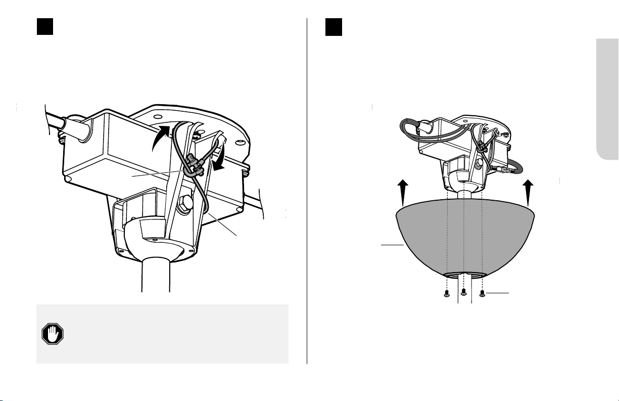
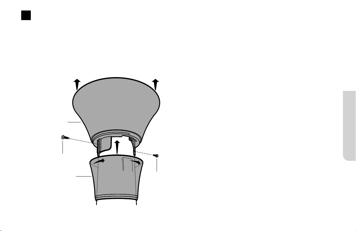
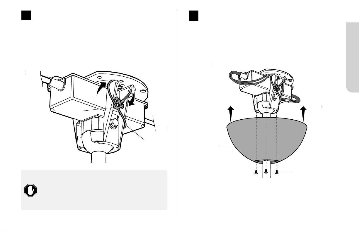
Mise en place du couvre-fils
Faites remonter le couvre-fils en veillant à laisser un espace
d’environ 3mm (1/8po) entre le couvre-fils et le plafond.
Alignez les fentes de fixation sur les trous de vis de la tige de
prolongation, puis fixez le couvre-fils à l’aide des vis prévues à
cet eet.
Faites remonter l’enjoliveur le long de la tige de prolongation
en alignant les ergots intérieurs sur les fentes de la partie
inférieure du couvre-fils. Enclenchez l’enjoliveur en le faisant
pivoter dans le sens des aiguilles d’une montre (fig.5).
5
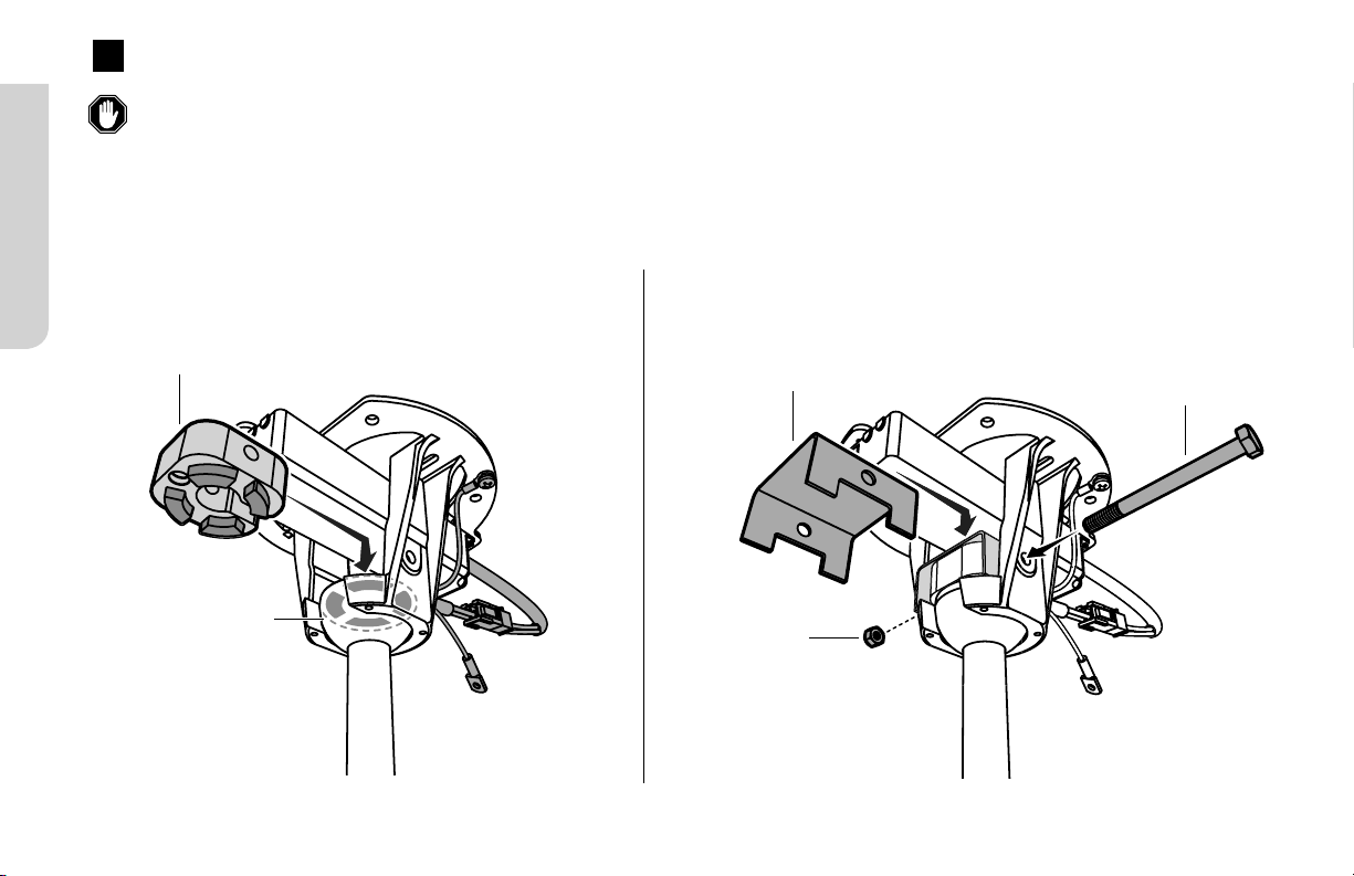
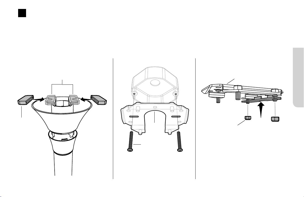
Montage des supports de fixation
Soulevez le ventilateur jusqu’au support de fixation. Glissez
l’un des blocs en caoutchouc entre la plaque de fixation et le
support de fixation préalablement monté (avec les écrous à
bague nylon de 6mm non serrés à fond).
Fixez l’autre bloc en caoutchouc à l’aide du support de fixation
et des écrous restants (fig.4).
Serrez tous les boulons à fond.
4
Support de
fixation
Fig.4
Écrou à bague
nylon 6mm
Vis
Couvre-fils
Enjoliveur pour
couvre-fils
Fig.5
Vis
Fixation courte
HAIKU® BY BIG ASS FANS
21
Montage des pales
En travaillant dans le sens des aiguilles d’une montre, alignez
chaque pale sur le moyeu, puis fixez-les à l’aide de la visserie
prévue à cet eet (fig.6). Veillez à faire correspondre les
couleurs des pastilles collées sur les pales et sur le moyeu!
VisM5
Œillet
6
Pale
Fig. 6
Fig. 7
7
Mise en place du cache inférieur
Fixez le cache inférieur comme illustré ci-dessous (fig.7).
Cache inférieur
Fixation standard
HAIKU® BY BIG ASS FANS
23
Utilisez les cache-vis pour tige de prolongation de la couleur de votre ventilateur.
Élingue de sécurité non représentée.
Support de fixation
Couvre-fils
Cache inférieur
Moyeu
FIXATION STANDARD
Œillet en caoutchouc
Enjoliveur pour couvre-fils
VisM5 (6)
Vis pour couvre-fils
Goupille fendue 2mm×2mm
Tés de renfort (2)
VisM8
Vis M6×25mm
ÉcrouM8
Rondelle Grower 8mm
ÉcrouM6
Pales (3)
Connecteurs électriques
Rondelle plate 8mm
Œillets (6)
Fixation standard
RÉV.D | © 2018 BIG ASS FANS | TOUS DROITS RÉSERVÉS
24
1 2
Fixation des tés de renfort
Fixez les tés de renfort à l’aide de la visserie fournie sans
serrer à fond (fig.2). La vis doit être introduite dans le trou du
milieu. Ne serrez pas le boulon à fond.
Œillet en
caoutchouc
Support de
fixation
Fig.1
Fig.2
Visserie de
montage
approprié
Mise en place du support de fixation
Insérez l’œillet en caoutchouc dans le support de fixation (fig.1).
Fixez le support de fixation à la structure d'ancrage à l’aide
des visserie de montage approprié (fig.1). La configuration
de votre structure d’ancrage peut être diérente de celle de
l’illustration.
Boîte de dérivation illustrée. La configuration de votre structure
d’ancrage peut être diérente de celle de l’illustration.
Té de renfort (2)
ÉcrouM6
Vis M6×25mm

Fixation standard
HAIKU® BY BIG ASS FANS
25
3
Suspension du ventilateur
Amenez la tige de prolongation jusqu’au support de fixation,
puis insérez les supports de la tige de prolongation entre les
tés de renfort et l’œillet en caoutchouc en veillant à aligner
les trous de fixation. Fixez la tige de prolongation à l’aide de la
visserie prévue à cet eet (fig.3).
Serrez le boulon à fond de sorte que les tés compriment
légèrement l’œillet en caoutchouc.
Mise en place de l’élingue de
sécurité
Tout en soutenant le ventilateur, passez l’élingue de sécurité
autour du support de fixation ou d’un élément structurel, puis
attachez-la à l’aide de la manille (fig.4).
4
Manille
Élingue de
sécurité
Fig.4
Canada: L’élingue de sécurité doit être directement
fixée à un élément structurel du bâtiment. Il est
parfois nécessaire d’installer des éléments structurels
supplémentaires pour créer des points d’attache.
Fig. 3
Rondelle plate
VisM8
Supports
Tige de prolongation
Rondelle Grower
Écrou
M8
Goupille
fendue
Couvre-fils
Enjoliveur pour
couvre-fils
Fixation standard
HAIKU® BY BIG ASS FANS
27
6
Mise en place du couvre-fils et de son enjoliveur
Faites remonter le couvre-fils en veillant à laisser un espace d’environ 3mm (1/8po) entre le couvre-fils et le plafond. Alignez les fentes
de fixation sur les trous de vis de la tige de prolongation, puis fixez le couvre-fils à l’aide des vis prévues à cet eet.
Faites remonter l’enjoliveur le long de la tige de prolongation en alignant les ergots intérieurs sur les fentes de la partie inférieure du
couvre-fils. Enclenchez l’enjoliveur en le faisant pivoter dans le sens des aiguilles d’une montre (fig.6).
Fig.6
Couvre-fils
Enjoliveur pour
couvre-fils
Vis
Vis

Fixation standard
HAIKU® BY BIG ASS FANS
29
Félicitations!
L’installation est terminée. Vous pouvez à présent tester votre ventilateur en utilisant la télécommande.
Si votre ventilateur est légèrement incliné, soulevez le cache situé au niveau du moteur et repérez la vis de pivotement.
Desserrez-la à l’aide d’une clé 6pans de 5mm, rectifiez l’aplomb du ventilateur, puis resserrez la vis.
Cache au niveau du moteur

ESPAÑOL

40 mm
Ø 8 mm
(perno de anclaje)
Ø 14 mm
(gancho de anclaje)
80 mm
100 mm
Montura de bajo perfil
2
REV. D | © 2018 BIG ASS FANS | TODOS LOS DERECHOS RESERVADOS
Techo de concreto
Si el código de construcción y seguridad local lo requiere, instale un gancho de anclaje para el cable de seguridad.
Ø 6 mm
112 mm
45 mm 43 mm
Ø 12–12.5 mm
45 mm
35 mm 35 mm
Montura estándar Montura universal
3
HAIKU® BY BIG ASS FANS
Montura de bajo perfil
Perfore cuatro agujeros Ø 8 mm como se muestra a continuación. La profundidad de los agujeros no debe exceder los
40mm. Quite el polvo de los agujeros. Inserte cuatro pernos de anclaje en los agujeros. Golpee las cabezas de los pernos
con un martillo, verificando que las camisas para anclaje estén a ras con la superficie del techo.
Ubique la placa de montaje sobre los pernos de anclaje. Verifique que los cuatro perno s estén totalmente ajustados
para así expandir y trabar los anclajes. Si los códigos locales de construcción y seguridad lo requieren, instale un
gancho de anclaje para el cable de seguridad. Perfore un agujero Ø 14 mm para el gancho de anclaje como se muestra
a continuación. La profundidad del agujero no debe exceder los 50 mm. Quite el polvo del agujero, inserte el gancho y
ajuste firmemente.
Montura estándar
Perfore tres agujeros Ø 12–12.5 mm como se muestra a continuación. La profundidad de los agujeros no debe exceder
los 35–40 mm. Quite el polvo de los agujeros. Inserte tres pernos de anclaje en los agujeros. Golpee las cabezas de
los pernos con un martillo, verificando que las camisas para anclaje estén a ras con la superficie del techo.
Ubique la placa de colgar sobre los pernos de anclaje. Verifique que los tres pernos estén totalmente ajustados para
así expandir y trabar los anclajes. Si los códigos locales de construcción y seguridad lo requieren, instale un gancho
de anclaje para el cable de seguridad. Perfore un agujero Ø 8–8.5 mm para el gancho de anclaje adyacente a la placa
de colgar. La profundidad de los agujeros no debe sobrepasar los 35–40 mm. Quite el polvo de los agujeros, inserte
el gancho y ajuste firmemente.
Montura universal
Perfores tres agujeros Ø 6 mm como se muestra a continuación. La profundidad de los agujeros no debe exceder
los 40 mm. Quite el polvo de los agujeros. Inserte tres pernos de anclaje en los agujeros. Golpee las cabezas de los
pernos con un martillo, verificando que las camisas para anclaje estén a ras con la superficie del techo.
Ubique el soporte de montaje sobre los pernos de anclaje. Verifique que los tres pernos estén totalmente ajustados
para así expandir y trabar los anclajes. Si los códigos locales de construcción y seguridad lo requieren, instale un
gancho de anclaje para el cable de seguridad. Perfore un agujero Ø 8 mm para el gancho de anclaje. La profundidad
del agujero no debe exceder los 50 mm. Quite el polvo del agujero, inserte el gancho y ajuste firmemente.
50 mm max.
40 mm max.
35–40 mm
35–40 mm
50 mm max.
40 mm max.

Montura universal
6
REV. D | © 2018 BIG ASS FANS | TODOS LOS DERECHOS RESERVADOS
MONTURA UNIVERSAL
No se muestra el cable de seguridad.
Si se incluye el filtro de interferencia electromagnética (filtro EMI), instálelo junto con el ventilador.
Para los techos inclinados, Big Ass Fans recomienda instalar el estabilizador para ventiladores en techo inclinado (disponible por separado).
Soporte de montaje
Campana
Tubo de extensión
Cubierta inferior
Tornillos M5 (6)
Tornillos de la campana (4)
Tapa del cableado
Aspas aerodinámicas (3)
Tuerca M6
Perno M6 x 32 mm
Estabilizador del ventilador
(solo para techos planos)
Arandela (6)
Bola y cuña de montaje
Cubo del motor
Conectores para cables
Pasador de acero de 6 mm
Montura universal
7
HAIKU® BY BIG ASS FANS
Instalar las aspas aerodinámicas
Moviéndose en el sentido de las manecillas del reloj, alinee
cada aspa aerodinámica en el cubo del ventilador y asegúrelas
con los accesorios de las aspas (Fig. 1). Verifique que el
color de la etiqueta de cada aspa aerodinámica coincida
con el color de la etiqueta correspondiente en el cubo del
ventilador.
Tornillo M5
Arandela
1
Aspa aerodinámica
Fig. 1
Fig. 2
2
Instalar la cubierta inferior
Coloque la cubierta inferior tal como se ilustra (Fig. 2).
Cubierta
inferior
Montura universal
8
REV. D | © 2018 BIG ASS FANS | TODOS LOS DERECHOS RESERVADOS
3
Colocar el tubo de extensión y el arnés del cableado
Alinee los agujeros del tubo de extensión con los agujeros del soporte del motor y luego asegure el tubo usando el perno M6 x 32mm
y la tuerca M6 (Fig. 3.1).
Conecte el arnés de cables del tubo de extensión al receptáculo del cubo del motor (Fig. 3.2).
Fig. 3.1 Fig. 3.2
Arnés del
cableado
Perno M6 x 32 mm
Tuerca M6

Montura universal
9
HAIKU® BY BIG ASS FANS
4
Instalar el cable de seguridad inferior y el cable de tierra
Instale los terminales del cable de seguridad y del cable a tierra con el tornillo sin pintar y la arandela de seguridad (Fig. 4.1).
Verifique que todos los accesorios estén bien asegurados y luego tire suavemente de los cables en la parte superior del tubo de
extensión para reducir la holgura (Fig.4.2).
Deslice la tapa del cableado hacia abajo por el tubo de extensión y apóyela sobre el cubo del ventilador. Verifique que no haya ningún
cable visible entre la tapa y el cubo del ventilador. Deslice la campana hacia abajo por el tubo de extensión (Fig.4.3).
Fig. 4.1 Fig. 4.2 Fig. 4.3
Tapa del
cableado
Campana
Cable de
seguridad
Cable de
tierra (verde)
Arandela de
seguridad
Tornillo

Montura universal
11
HAIKU® BY BIG ASS FANS
Instalar el soporte de montaje
¡Desconecte la alimentación eléctrica antes de instalar el
soporte de montaje!
Asegure el soporte de montaje a la estructura de montaje
usando accesorios de montaje adecuado (Fig. 6).
Caja de distribución que se muestra. La estructura de
montaje puede diferir de la ilustración.
6
Fig. 6
Accesorios de montaje
adecuado
Soporte de
montaje
7
Colgar el ventilador
Suba el ventilador hasta el soporte de montaje. Alinee la
pestaña del soporte de montaje con la ranura de la bola de
montaje, ubique la bola de montaje y permita que el ventilador
cuelgue libremente (Fig. 7).
Gire cuidadosamente el tubo de extensión para verificar
que esté bien asentado y que no se moverá durante el
funcionamiento del ventilador.
Fig. 7
Soporte de
montaje
Bola de
montaje

Montura universal
13
HAIKU® BY BIG ASS FANS
Diagrama de cableado
(Sin filtro EMI)
BLANCO
NEGRO
MARRÓN
AZUL
BLANCO
NEGRO
MARRÓN
AZUL
FILTRO EMI
Diagrama de cableado
(Con filtro EMI)
VERDE Y
AMARILLO
VERDE Y
AMARILLO

Montura universal
14
REV. D | © 2018 BIG ASS FANS | TODOS LOS DERECHOS RESERVADOS
Instalar el estabilizador para ventiladores en techo plano
Si va a instalar su ventilador en un techo inclinado, Big Ass Fans recomienda instalar el estabilizador para ventiladores en
techo inclinado.
Coloque el bloque estabilizador en las muescas de la parte superior de la bola de montaje (Fig. 9.1).
Asegure la placa estabilizadora al bloque estabilizador usando el perno M6 x 70 mm y la tuerca M6 (Fig. 9.2).
9
Bloque
estabilizador
Bola de
montaje
Placa
estabilizadora
Perno M6 x 70mm
Tuerca M6
Fig. 9.1 Fig. 9.2
Montura universal
15
HAIKU® BY BIG ASS FANS
11
Subir la campana
Suba la campana hasta el soporte de montaje, alineando los
cuatro agujeros de la campana con los agujeros del soporte.
Asegure la campana al soporte de montaje con los tornillos
pintados (Fig.11). Verifique que todos los cables, incluido el
cable de seguridad, estén dentro de la campana.
10
Asegurar el cable de seguridad
Haga pasar el cable de seguridad alrededor del soporte de
montaje o la estructura del edificio y luego asegúrelo con el
grillete (Fig. 10).
Canadá: El cable de seguridad debe asegurarse
directamente a una parte existente de la
estructura del edificio. Puede ser necesario
instalar materiales estructurales adicionales para
proveer puntos de fijación adecuados.
Cable de seguridad
Grillete
Campana
Tornillo de la
campana
Fig. 10
Fig. 11
¡Felicitaciones!
Ha terminado la instalación. Pruebe el ventilador usando el
control remoto.

Montura de bajo perfil
REV. D | © 2018 BIG ASS FANS | TODOS LOS DERECHOS RESERVADOS
16
MONTURA DE BAJO PERFIL
Para el tubo de extensión, utilice los cubretornillos que coincidan con el color de su ventilador.
No se muestra el cable de seguridad.
Placa de montaje
Amortiguadores de goma (2)
Soportes de montaje (2)
Tuercas Nylock de 6 mm (4)
Cubretornillos para el tubo de extensión (2)
Cubierta inferior
Arandelas (6)
Tornillos M5 (6)
Cubo del motor
Tornillos de la tapa del cableado (2)
Aspas aerodinámicas (3)
Conectores para cables
Tapa del cableado
Pieza de acabado
Montura de bajo perfil
HAIKU® BY BIG ASS FANS
17
Instalar la placa de montaje y un soporte
Coloque los amortiguadores de goma en los soportes del tubo de extensión (Fig. 1.1).
Asegure el soporte de montaje a la estructura de montaje usando accesorios de montaje adecuado (Fig. 1.2). La estructura de montaje
puede diferir de la ilustración.
Asegure un soporte de montaje a la placa de montaje usando dos tuercas Nylock de 6mm, pero no las ajuste totalmente (Fig. 1.3).
Fig. 1.1 Fig. 1.2
1
Fig. 1.3
Amortiguador
de goma
Soportes del tubo de extensión
Tuerca Nylock
de 6 mm
Accesorios de
montaje adecuado
Placa de
montaje
Caja de distribución que se muestra.
La estructura de montaje puede
diferir de la ilustración.
Plaque de fixation
Montura de bajo perfil
HAIKU® BY BIG ASS FANS
19
Cablear el ventilador
¡Desconecte la alimentación eléctrica antes de cablear el
ventilador!
¡Nunca conecte el ventilador a una fuente de alimentación
dañada! No intente reparar desperfectos eléctricos por su
cuenta. Si tiene alguna duda sobre la instalación eléctrica de este
ventilador, consulte a un electricista calificado.
Permita que el ventilador cuelgue del cable de seguridad.Conecte
los cables del ventilador como se muestra en el diagrama usando los
conectores para cables (Fig. 3).
Fig. 3
3
Diagrama de cableado
AZUL
MARRÓN
BLANCO
NEGRO
VERDE Y
AMARILLO
América del Norte
100–120 V
Todas las demás
regiones
Vivo CA/L1
Marrón
Negro Marrón
Neutro CA/ L2
Azul
Blanco Azul
Tierra de protección/Tierra
Verde con amarillo
Verde o cobre
desnudo
Verde con amarillo

Montura estándar
HAIKU® BY BIG ASS FANS
23
Para el tubo de extensión, utilice los cubretornillos que coincidan con el color de su ventilador.
No se muestra el cable de seguridad.
Soporte de montaje
Tapa del cableado
Cubierta inferior
Cubo del motor
MONTURA ESTÁNDAR
Casquillo de goma
Pieza de acabado
Tornillos M5 (6)
Tornillos de la tapa del cableado
Chaveta partida 2 mm x 2 mm
Soporte para sujeción del montaje (2)
Perno M8
Tornillo M6 x 25 mm
Tuerca M8
Arandela de seguridad de 8 mm
Tuerca M6
Aspas aerodinámicas (3)
Conectores para cables
Arandela plana 8mm
Arandelas (6)

Montura estándar
REV. D | © 2018 BIG ASS FANS | TODOS LOS DERECHOS RESERVADOS
24
1
Instalar el soporte de montaje
Coloque el casquillo de goma en el soporte de montaje (Fig. 1).
Asegure el soporte de montaje a la estructura de montaje
usando accesorios de montaje adecuado (Fig. 1). La estructura
de montaje puede diferir de la ilustración.
2
Asegurar los soportes para
sujeción del montaje
Instale los soportes del sujetador para montaje usando los
accesorios provistos, pero no los apriete demasiado (Fig. 2).
El perno se debe insertar en el agujero del medio. No ajuste
totalmente los accesorios.
Soporte para sujeción
del montaje (2)
Tuerca M6
Tornillo M6 x 25 mm
Fig. 2
Caja de distribución que se muestra. La estructura de
montaje puede diferir de la ilustración.
Casquillo
de goma
Soporte de
montaje
Fig. 1
Accesorios de
montaje adecuado
Montura estándar
HAIKU® BY BIG ASS FANS
25
3
Colgar el ventilador
Levante el tubo de extensión hasta la montura e inserte los
soportes del tubo entre los soportes de montaje y el casquillo
de goma de manera que los agujeros de montaje estén
alineados. Asegure el tubo de extensión con los accesorios de
montaje (Fig. 3).
Apriete bien todos los accesorios hasta que los
soportes compriman levemente el casquillo de goma.
Asegurar el cable de seguridad
Mientras sostiene el ventilador, haga pasar el cable de
seguridad alrededor del soporte de montaje o la estructura del
edificio y luego asegúrelo con el grillete (Fig.4).
4
Grillete
Cable de
seguridad
Fig. 4
Canadá: El cable de seguridad debe asegurarse
directamente a una parte existente de la
estructura del edificio. Puede ser necesario
instalar materiales estructurales adicionales para
proveer puntos de fijación adecuados.
Fig. 3
Arandela plana
Perno M8
Soportes
Tubo de extensión
Arandela de
seguridad
Tuerca M8
Chaveta
partida
Tapa del
cableado
Pieza de acabado

Montura estándar
HAIKU® BY BIG ASS FANS
29
¡Felicitaciones!
Ha terminado la instalación. Pruebe el ventilador usando el control remoto.
Si su ventilador parece estar algo inclinado, levante la pieza de acabado de la cubierta inferior del motor y ubique el perno de
pivote. Afloje este perno con una llave hexagonal de 5mm para permitir que el ventilador cuelgue libremente y luego vuelva a
ajustarlo.
Cubierta inferior del motor

30
REV. D | © 2018 BIG ASS FANS | TODOS LOS DERECHOS RESERVADOS
RESOLUCIÓN DE PROBLEMAS
En ocasiones, puede que el ventilador se sacuda hacia adelante y hacia atrás en el arranque. Esto es normal y no afecta su funcionamiento.
Antes de comunicarse con el Servicio de Atención al Cliente, intente resolver el problema con los siguientes pasos. Para obtener más información sobre
el funcionamiento, mantenimiento y resolución de problemas, visite bigassfans.com/support
Problema Solución
El ventilador no enciende.
• Verifique que el ventilador esté recibiendo energía.
• Revise el disyuntor o fusible y el interruptor de pared para verificar que funcionen.
• Verifique que el ventilador esté correctamente cableado y conectado a tierra.
• Verifique que se haya retirado el plástico protector de la bandeja de baterías del control
remoto.
El ventilador se tambalea.
Quite las aspas aerodinámicas y verifique que la etiqueta con un punto de color de cada aspa
coincida con la etiqueta correspondiente en el cubo del motor. Si las etiquetas no coinciden,
mueva las aspas a los puntos de fijación correspondientes.
El ventilador parece estar inclinado.
(Solo monturas de bajo perfil y estándares)
Levante la pieza de acabado de la cubierta inferior del motor y ubique el perno de pivote. Afloje
este perno con una llave hexagonal de 5mm para permitir que el ventilador cuelgue libremente y
luego vuelva a ajustarlo.
El ventilador hace demasiado ruido.
Detenga completamente el ventilador.
• Haga girar suavemente las aspas aerodinámicas (a mano) y verifique que ninguna parte del
ventilador roce contra el cubo del motor mientras está girando.
• Revise todos los accesorios de instalación y elementos de fijación del ventilador. Ajústelos si
es necesario.
Debo reiniciar el ventilador.
Presione el botón de encendido hasta que los indicadores LED comiencen a destellar.
Una vez que los LED hayan destellado durante tres segundos, presione nuevamente el botón de
encendido. Cuando los LED dejan de destellar, significa que el ventilador se ha reiniciado.

NOTES

Models:
FR127A-A2, FR127A-S0, FR127A-U0, FR150A-A2, FR150A-S0, FR150A-U0, FR213A-U0
© 2018 Big Ass Fans
The information contained in this document is subject to change without notice. May be protected by one or more patents listed at www.bigassfans.com/patents
Haiku is a trademark of Delta T LLC, registered in the U.S. and/or other countries.
For warranty information, visit www.bigassfans.com/product-warranties
United States
2348 Innovation Drive
Lexington, KY 40511
bigassfans.com
+1 855 694 2458
Canada
6300 Northwest Dr, Unit 3
Mississauga, ON L4V 1J7, Canada
bigassfans.com
+1 844 424 5848
Australia
35 French Street
Eagle Farm, Brisbane, QLD 4009
bigassfans.com/au
+61 1300 244 277
Southeast Asia
18 Tampines Industrial Crescent
#06-07
Singapore 528 605
bigassfans.com/sg
Singapore: +65 6709 8503
Malaysia: +603 5565 0888
Mexico
CEBSA (Corporación Eléctrica del
Bravo SA de CV)
Avenida Ind. Rio San Juan
Lote 3-A Parque Industrial del Norte
Reynosa, Tamps C.P. 88736
http://cebsainc.com/
+52 1 899 925 6398
All Other Geographies
2348 Innovation Drive
Lexington, KY 40511
bigassfans.com
+1 859 233 1271