
Loading ...
Loading ...
Loading ...
4
ENGLISH
3.3 Subwoofer Foot Options
DB Series subwoofers must not be
used without one of the foot options tted.
DB Series subwoofers can be tted with either
decoupling, rubber or spike feet. Use of
the different foot types is described in the
following paragraphs:
• The spike feet are intended for use on carpeted
oors. The spikes pierce the carpet and rest on
the oor beneath both to protect the carpet from
indentation and to provide the subwoofer with a
solid foundation.
• The decoupling feet are intended to be used on
suspended wooden oors. The rubber material of
the foot provides a degree of de-coupling
between the oor and subwoofer.
• The rubber feet are intended for use on non-
carpeted solid oors where spike feet might
cause damage the surface.
Due to the underside location of
the subwoofer heat-sink, rubber or
decoupling feet should not be used on
carpeted oors.
In order for feet to be tted to the subwoofer it
must rst be turned upside-down. Take care not
to damage the drive units when handling the
subwoofer, and ensure when upside-down that
the subwoofer rests on a surface that will not
damage its nish.
Fit the feet by screwing one into each of the four
screw holes in the subwoofer underside. In the
case of spike feet, initially screw the lock nuts fully
onto the thread before screwing the feet into the
subwoofer. The lock nut should then be used to
raise the subwoofer above the carpet pile and to
enable adjustment to minimise rocking.
Note: It is important to raise the subwoofer
above the carpet pile to ensure that cooling air
can ow around the subwoofer amplier heat-
sink panel.
Diagrams 2a and 2b illustrate the use of each
foot type.
Once the feet are tted, the subwoofer can be
turned back on to its feet. Take care not to allow the
entire weight of the subwoofer to rest at an angle on
one or two feet.
Never slide the subwoofer across the
oor on its feet. It must be lifted if it is
to be moved.
If the subwoofer rocks when placed on the oor in
its nal position on spike feet, or the thickness of
carpet means that the spike points do not reach the
oor beneath, adjust the feet until the subwoofer is
supported rmly without rocking and is well clear
of the carpet pile. When adjustment is complete,
tighten all the lock nuts against the underside of the
subwoofer using a 10mm spanner.
3.4 Subwoofer Grilles
Your DB Series subwoofer is supplied with
optional fabric covered grilles. The subwoofer can
be used with or without grilles tted. The grilles are
attached magnetically.
3.5 Connections
DB Series subwoofers require connection to a mains
power supply and an input signal. Connectors
for optional 12V trigger and RS232 control are
also provided. Diagram 3 illustrates the DB Series
subwoofer connection panel.
Mains Power
A variety of different power cables may be packed
with your subwoofer. Use the cable appropriate for
the mains socket in your territory. The subwoofer
will switch on in operational mode, with its front
panel standby button indicator illuminated green,
as soon as it is connected to mains power. If the
subwoofer remains unused for more than 20 minutes
it will automatically switch to standby mode with the
indicator illuminated red.
Signal Connections
DB Series subwoofers provide stereo RCA Phono
and stereo balanced XLR inputs. It is possible to
use the Phono and XLR sockets as independently
selectable inputs. This enables your subwoofer to be
integrated with two different audio systems: a home
theatre system and a conventional stereo system
for example. Input selection is managed via the DB
Subwoofers app.
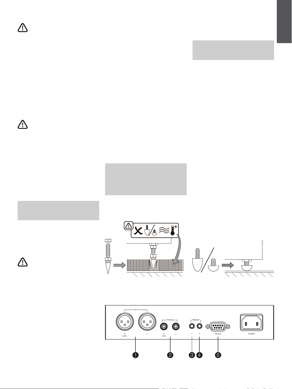
1 - XLR inputs
The balanced XLR inputs are intended for use with
preampliers or audio-visual processors that provide
balanced stereo outputs.
Note: Balanced connection, where negative,
positive and ground signals are carried on
separate wires, is common in professional and
some high-end domestic audio equipment.
Balanced connection is inherently more
resistant to interference and noise than
unbalanced connection.
Diagram 3
DB subwoofer connection panel
Diagram 2b
Using decoupling and rubber feet
2 - RCA Phono inputs
The unbalanced RCA Phono inputs are intended for
use with preampliers or audio-visual processors
that provide unbalanced balanced stereo outputs.
Note: If your preamplier or audio-visual
processor provides only a mono subwoofer
output, it can be connected to just one of the
subwoofer input sockets.
Control Connections
In addition to mains and signal input sockets the
DB Series subwoofer connection panel carries the
following optional control interface sockets:
3 - 12V Trigger 1: 3.5mm jack socket
The Trigger 1 socket enables wired remote control of
the subwoofer switch on and standby functions.
4 - 12V Trigger : 3.5mm jack socket
The Trigger 2 socket enables wired remote control of
subwoofer input selection.
5 - RS-232: 9-pin D connector
The RS232 interface enables subwoofers to be
incorporated in remote control home automation
systems. Your Bowers & Wilkins retailer will be able
to provide more information on RS232 based home
automation systems.
Diagram 2a
Using spike feet
Loading ...
Loading ...
Loading ...