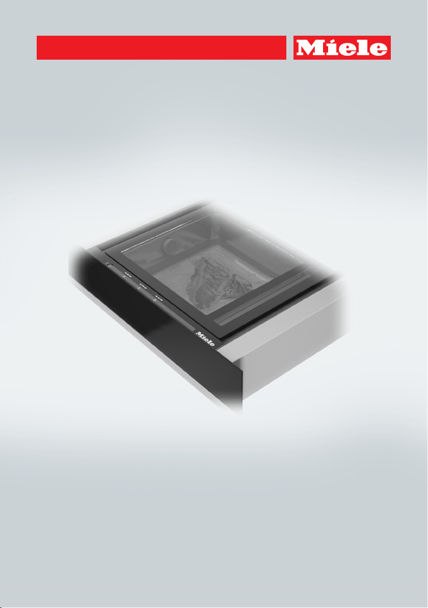
Operating and Installation Instructions
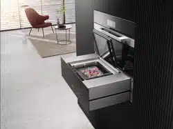
Built-in Vacuum-Sealing Drawer
To prevent accidents and machine damage, read these instructions be-
fore installation or use.
en-US M.-Nr. 10 927 120

Contents
2
IMPORTANT SAFETY INSTRUCTIONS ................................................................ 4
Caring for the environment ................................................................................ 12
Overview............................................................................................................... 13
Overview of the drawer ......................................................................................... 13
Standard accessories............................................................................................ 14
Controls and display ........................................................................................... 15
Cleaning for the first time................................................................................... 16
Operation.............................................................................................................. 17
Suitable vacuum bags........................................................................................... 17
Important information on use ................................................................................ 17
Tips........................................................................................................................ 18
Using the vacuum levels ....................................................................................... 19
Using the sealing levels......................................................................................... 20
Vacuuming and sealing bags ................................................................................ 21
Sealing the bag early........................................................................................22
Vacuum-sealing third-party containers ................................................................. 23
After use ................................................................................................................ 25
Canceling a vacuuming process ........................................................................... 25
Cleaning and care ............................................................................................... 26
Cleaning the drawer front and glass lid................................................................. 27
Cleaning the vacuum chamber and sealing bar.................................................... 27
Cleaning the vacuum adapter ............................................................................... 27
Completing a drying cycle..................................................................................... 28
Frequently Asked Questions .............................................................................. 29
IMPORTANT SAFETY INSTRUCTIONS - INSTALLATION ................................. 34
Instructions for installation ................................................................................ 35
Installation dimensions ...................................................................................... 36
Installation............................................................................................................ 40
Electrical connection .......................................................................................... 45
Technical Service................................................................................................. 47
Contact in case of fault ......................................................................................... 47
Data plate .............................................................................................................. 47
Warranty ................................................................................................................ 47

IMPORTANT SAFETY INSTRUCTIONS
4
Please note that the vacuum-sealing drawer is referred to as the drawer in these
operating instructions.
This drawer conforms to current safety requirements. Improper
use can, however, lead to personal injury and damage to property.
To avoid the risk of accidents and damage to the appliance,
please read these instructions carefully before using the appliance
for the first time. They contain important notes on installation,
safety, use and maintenance.
Miele cannot be held liable for damage occurring as a result of
non-compliance with these instructions.
Keep these instructions in a safe place and pass them on to any
future owners.

IMPORTANT SAFETY INSTRUCTIONS
5
Appropriate use
This drawer is intended for domestic use and use in other similar
environments.
The drawer is not intended for outdoor use.
The drawer is only for domestic use to vacuum and seal food in
vacuum bags intended for this purpose and to vacuum-seal food in
vacuum-proof containers made of plastic or stainless steel.
All other types of use are not permitted.
Never vacuum-seal live food (e.g., mussels, seafood).
Persons who lack physical, sensory or mental abilities, or experi-
ence with the appliance should not use it without supervision or in-
struction by a responsible person.

IMPORTANT SAFETY INSTRUCTIONS
6
Safety with children
Children must be kept away from the drawer unless they are con-
stantly supervised.
Be sure to supervise any children in the vicinity of the drawer, and
do not let them play with it.
The sealing bar becomes hot during operation. The weld seam of
the vacuum bag is also heated to a very high temperature during the
sealing process. Keep children away from the drawer until the seal-
ing bar and the seam have cooled sufficiently that there is no longer
any danger of burning.
Danger of suffocation! Ensure that any plastic wrappings, bags,
etc. are disposed of safely and kept out of the reach of children.

IMPORTANT SAFETY INSTRUCTIONS
7
Technical safety
Unauthorized installation, maintenance, and repairs can cause
considerable danger for the user. Installation, maintenance, and re-
pairs must only be carried out by a Miele authorized technician.
A damaged drawer can be dangerous. Always check for visible
signs of damage. Never use a damaged appliance.
Pay attention to any damage or cracks to the glass lid or chamber
seal. Damage to the glass lid can cause implosion. Never operate
the drawer if the glass lid and/or the chamber seal is damaged.
The drawer has an integrated vacuum pump, which contains oil.
To prevent oil from leaking out, the drawer must be transported and
stored in a horizontal position only. Do not tilt the drawer and do not
stand it up on its side.
The manufacturer's warranty will be invalidated if oil has leaked out
of the appliance because it has not been transported or stored cor-
rectly.
Reliable and safe operation of the drawer can only be assured if it
has been connected to the electrical supply.
Be certain the drawer is properly installed and grounded by a
qualified technician. To guarantee the electrical safety of this appli-
ance, continuity must exist between the appliance and an effective
grounding system. It is imperative that this basic safety requirement
be met. If there is any doubt, have the electrical system of the house
checked by a qualified electrician.
The connection data (voltage and frequency) on the data plate of
the drawer must match the line power in order to avoid the risk of
damage to the drawer. Compare this data before connecting the ap-
pliance. If in doubt, consult a suitably qualified electrician.
Do not connect the drawer to the electrical supply with a power
bar or extension cord. These are a fire hazard and do not guarantee
the required safety of the appliance.

IMPORTANT SAFETY INSTRUCTIONS
8
For safety reasons, the drawer may only be used when it has been
fully installed.
This drawer may not be used in non-stationary locations (e.g. on a
ship).
Any contact with live connections or tampering with the electrical
or mechanical components of the drawer will endanger your safety
and may lead to appliance malfunctions.
Do not open the casing of the drawer under any circumstances.
Do not operate the drawer with wet hands or if you are in contact
with water.
Any repairs not performed by a Miele authorized service techni-
cian will void the warranty.
Defective components should be replaced by Miele original parts
only. Only with these parts can the manufacturer guarantee the
safety of the appliance.
If the plug has been removed or the power cord is not supplied
with a plug, the drawer must be connected to the power supply by a
suitably qualified electrician.
If the power cord is damaged, it must be replaced with a special
power cord (see “Electrical connection”).
If power is interrupted during vacuum-sealing, the vacuum in the
chamber is retained and the glass lid cannot be opened. Do not un-
der any circumstances try to force the glass lid open or use tools to
open it. You will be able to open the lid when power has been re-
stored.

IMPORTANT SAFETY INSTRUCTIONS
9
The drawer must be completely disconnected from the power
supply during installation, maintenance and repair work. This can be
ensured as follows:
– The circuit breaker has tripped, or
– The fuse of the electrical installation is completely removed, or
– The plug (if present) is removed from the outlet. In the process,
pull the plug not the cord.
If the drawer is installed behind a cabinet panel (e.g., a door), en-
sure that the door is never closed while the drawer is in use. Heat
and moisture can build up behind a closed cabinet panel and cause
subsequent damage to the drawer, the housing unit, and the floor.
Do not close the door until the sealing bar and the drawer have
cooled down completely.

IMPORTANT SAFETY INSTRUCTIONS
10
Correct use
Danger of burning. The sealing bar becomes hot during operation.
The weld seam of the vacuum-sealing bag is also heated to a very
high temperature during the sealing process. Do not touch the seal-
ing bar or the seam immediately after the vacuum-sealing process.
Fire hazard. Do not store any easily flammable substances and
materials in the vicinity of the drawer.
The maximum load capacity of the telescopic drawer rails is
55lbs (15kg). If you overload the drawer or lean/stand on it when it
is open, you will damage the rails.
Damage to the glass lid can cause implosion. Do not place any
objects on the glass lid. Ensure that the glass lid cannot sustain
damage from falling objects.
Do not use the drawer or the glass lid as a work surface, a chop-
ping surface, or a shelf.
The drawer must be installed so that it can be pulled out com-
pletely and there is sufficient room to open the glass lid. This en-
sures that you can see into the vacuum chamber and avoid touching
the sealing bar and weld seam and burning yourself.
When vacuuming liquids, bubbles can form at lower temperatures
which will cause an impression of boiling. Steam can escape, which
can cause the drawer to malfunction.
For this reason, only vacuum-seal food (liquid or solid) when it has
cooled. Follow the vacuuming process carefully and seal the bag
early if necessary.
If liquid gets into the drawer and the vacuum pump air intake
valve, this can result in damage to the vacuum pump.
Moisture in food or drinks can cause corrosion damage in the
drawer. Do not use the drawer to store food or drinks.
Miele does not permit vacuum-sealing of glass containers.
IMPORTANT SAFETY INSTRUCTIONS
11
Never insert the tubes attached to the drawer into any body ori-
fices.
Cleaning and maintenance
Do not use a steam cleaner to clean the drawer.
The steam may reach electrical components and cause a short cir-
cuit.
SAVE THESE INSTRUCTIONS AND REVIEW THEM PERIODICALLY
Caring for the environment
12
Disposal of the packing mate-
rial
The cardboard box and packing materi-
als protect the appliance during ship-
ping. They have been designed to be
biodegradable and recyclable.
Ensure that any plastic wrappings,
bags, etc. are disposed of safely and
kept out of the reach of children. Dan-
ger of suffocation!
Disposal of your old appliance
Electrical and electronic appliances
contain valuable materials. They also
contain certain substances, compounds
and components which were essential
for the proper functioning and safe use
of the equipment. Handling these mate-
rials improperly by disposing of them in
your household waste can be harmful to
your health and the environment. There-
fore, please do not dispose of your old
appliance with regular household waste
and follow local regulations on proper
disposal.
Consult with local authorities, dealers or
Miele in order to dispose of and recycle
electrical and electronic appliances.
Miele assumes no responsibility for
deleting any personal data left on the
appliance being disposed. Please en-
sure that your old appliance is kept
away from children until removal. Ob-
serve safety requirements for appli-
ances that may tip over or pose an en-
trapment hazard.
Overview
13
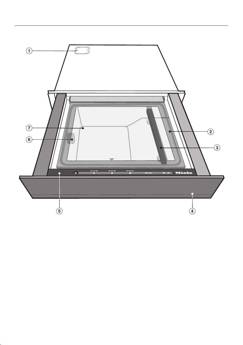
Overview of the drawer
a
Air filter cover (see “Installation”)
b
Glass lid with chamber seal
Push down on the little black triangle
to close the glass lid.
c
Sealing bar in the vacuum chamber
and counterpressure bar on the un-
derside of the glass lid
d
Push2open mechanism
The drawer can be opened by press-
ing lightly in the middle of the drawer
front.
e
Control panel
f
Vacuum pump air intake valve / vac-
uum adapter connection
g
Vacuum chamber

Overview
14
Standard accessories
Vacuum adapter
1adapter for vacuum-sealing third-
party containers
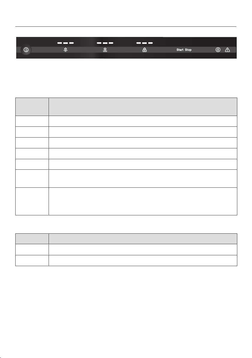
Controls and display
15
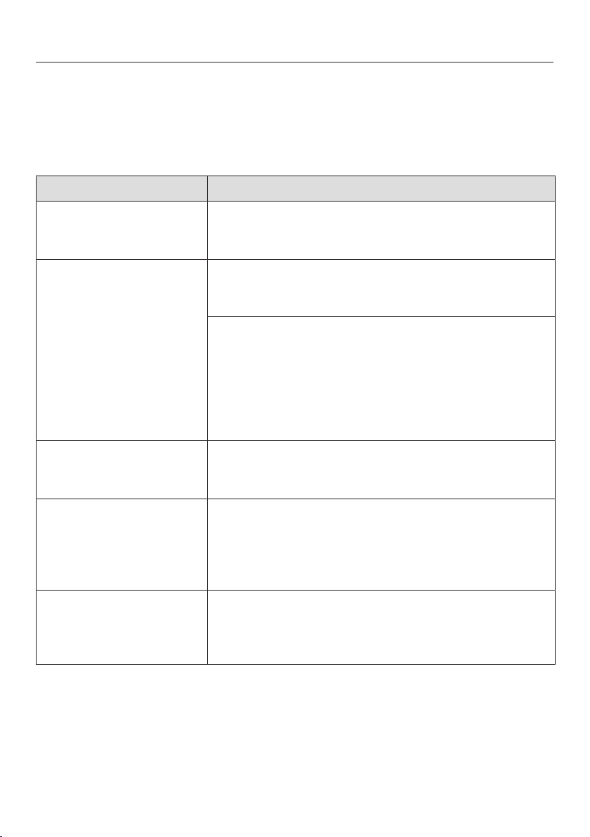
Sensor buttons
The sensors react to touch. Every touch on the sensors is confirmed by an audible
tone.
Sensor
button
Function
Switching on and off
Setting the vacuum level
Setting the sealing level / sealing the vacuum bag early
Setting the vacuum level for third-party containers
Starting the vacuuming process for third-party containers
Canceling the vacuuming / sealing process or canceling the drying
cycle
Completing the drying cycle
Note: This sensor only lights up if a drying cycle needs to be carried
out (see “Cleaning and care – Completing a drying cycle”).
Indicators
Indicator Description
Vacuum / sealing level indicators
Warning (see “Frequently asked questions”)
Cleaning for the first time
16
Please stick the extra data plate for
the appliance, supplied with this doc-
umentation, in the space provided in
the “After sales service, data plate,
warranty” section of this booklet.
Remove any protective foil and sales
stickers.
Stickers carrying safety or installation
information and the data plate must
not be removed.
Cleaning the drawer for the
first time
Take all accessories out of the
drawer.
Take care not to damage the
glass lid and the chamber seal.
Do not clean with any abrasive or
acidic cleaning agents or sharp
pointed objects.
Clean the drawer inside and out with
a clean sponge and a mild solution of
warm water and liquid dish soap or a
clean, damp microfiber cloth.
After cleaning, wipe the surfaces dry
using a soft cloth.

Operation
17
Suitable vacuum bags
Only vacuum bags meeting the follow-
ing material requirements are permitted
for use:
– Suitable for use with food
– Suitable for freezing and cooking
– Suitable for storing and sous-vide
cooking of liquid and solid food
– Maximum size:
9⁷/₁₆"x13³/₄" (240x350mm)
(tubular bags)/
9 ³/₄" x 13 ³/₄" (250 x 350mm)
(sealed edge bags)
– Properties: preferably smooth
– Made from PA/PE, not printed on the
inside
– Thickness: 90µm, typical
– Suitable for vacuum-sealing
<10mBar
– Suitable for hot-foil sealing
– No migration of hazardous materials
or chemicals, e.g.,plasticizers, into
the food being vacuum-sealed
Miele does not permit the use of vac-
uum bags inside microwaves.
Important information on use
Miele does not permit vacuum-seal-
ing of glass containers.
– Only vacuum-seal food.
– Only use food that is fresh and in
good condition.
– Ensure hygienic conditions and that
food has not been out of the refriger-
ator too long.
– Only vacuum-seal food in suitable
vacuum bags or in vacuum-proof ex-
ternal containers.
– Only vacuum seal food that has
cooled.
– Allow pre-cooked and broiled food to
cool down at least to room tempera-
ture (approx. 68°F (20°C)) before vac-
uum-sealing it.
Food that is not normally stored in
the refrigerator, such as dried pasta
or oatmeal, can also be vacuum-
sealed at room temperature.
– If rinsing food with cold water, dry it
before vacuum-sealing to prevent
water from collecting in the vacuum
bag or container.
– Select a suitable bag size for the size
of the food. If the vacuum bag is too
big, too much air can remain inside.
The bag can be cut to fit the size of
the food.
– If you want to vacuum-seal several
types of food in one bag, place the
food evenly side-by-side in the bag.

Operation
18
– Fill the vacuum bag to a maximum of
²/₃ with solid food or ¹/₃ with liquid.
– For a perfect weld seam, make sure
that the edge of the bag is dry and
grease-free in the area of the seam.
– Position the open edge of the bag
parallel to the sealing bar so that the
edge protrudes over the sealing bar
by approx. ³/₄" (2cm).
– Take care not to cover the vacuum
pump air intake valve with the bag.
– Vacuum bags are for single use only.
– Place food that is suitable for cooling
in the refrigerator or freezer after vac-
uum-sealing it.
Tips
– Freeze liquids before vacuum-sealing
them. You can then fill the bags ²/₃
full.
– Fold the edges of the vacuum-sealing
bag outward for filling. This will give
you clean, perfect weld seams.
– To prevent small bags from slipping
down into the vacuum chamber, a
chopping board can be placed in the
bottom of the chamber.
– If you are unsure whether food such
as berries or crisps will lose its shape
during vacuum-sealing, start with the
lowest vacuum-sealing level.
Operation
19
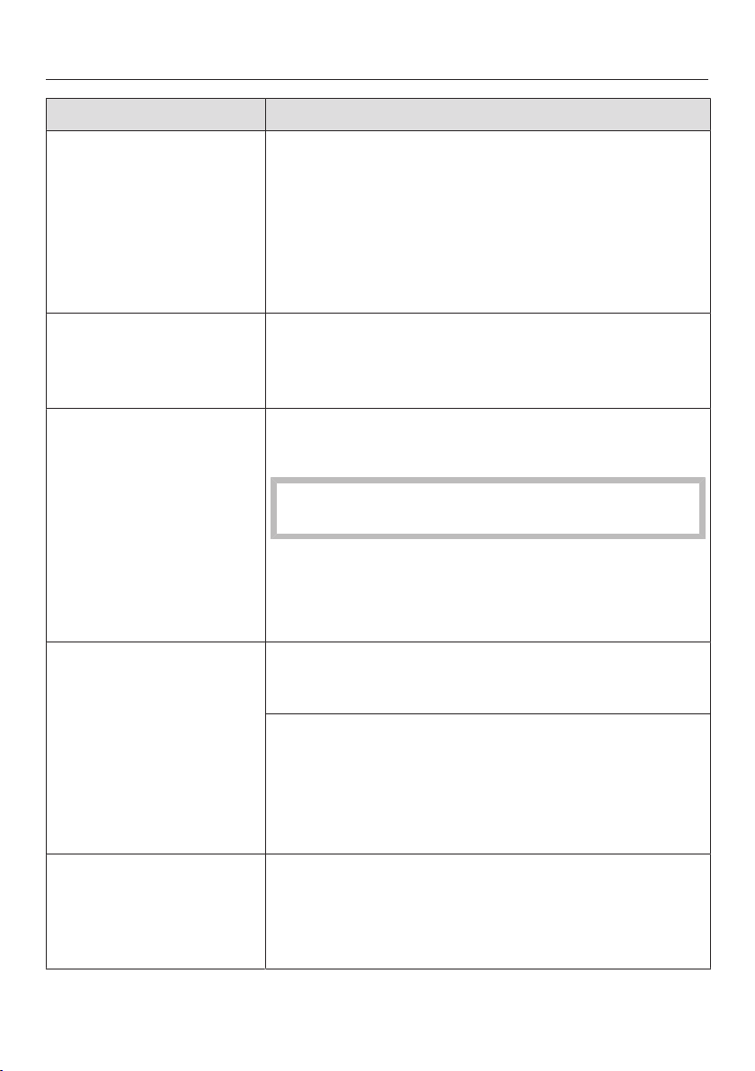
Using the vacuum levels
There are 3levels for vacuum sealing.
The higher the vacuum level selected, the greater the vacuum.
Vacuum
level
Intended use
Packaging, portioning, and storing
Suitable for
– Food that is prone to squashing, e.g.,lettuce, berries, or chips
Marinating, tenderizing, sous-vide cooking, and freezing
Suitable for
– Food that is prone to squashing, e.g.,tender fish fillets
– Sauces and food with a high liquid content(≥1.8 ox (50g)),
e.g.,ragout, curry
Sous-vide cooking, freezing, and storage
Suitable for
– Meat and more solid food, e.g.,potatoes, carrots
– Hard cheese (storage)
– Food with a low liquid content (≤1.8 ox (50g)), such as meat
seasoned with a herb oil

Operation
20
Using the sealing levels
There are 3levels for sealing vacuum bags.
The choice of sealing level depends on the material thickness of the bag: the
thicker the bag, the higher the sealing level.
Tip: The sealing bar will get progressively hotter when carrying out a number of
consecutive vacuuming processes. You can use a lower sealing level after sealing
a few bags.
Operation
21
Risk of injury!
Damage to the glass lid can cause
implosion.
Do not under any circumstances use
the drawer if the glass lid is dam-
aged.
Soiling and liquid must not be al-
lowed to get on the sensors. Other-
wise, the sensors will fail to react or
switch on or off unintentionally.
Do not damage the drawer!
If liquid gets into the vacuum pump
air intake valve during a vacuuming
process, this can result in damage to
the vacuum pump.
Fill the vacuum-sealing bag with liq-
uid to a maximum of ¹/₃.
Vacuuming and sealing bags
Fill the vacuum-sealing bag.
Open the drawer and the glass lid.
Place the vacuum-sealing bag in the
vacuum chamber so that the open
end of the bag lies across the sealing
bar. Ensure that the edge of the bag
is positioned centrally on the sealing
bar and is free from creases.
Switch the drawer on with the sen-
sor.
The and sensors will light up.
Touch the sensor repeatedly until
the segment for the required vacuum
level lights up.
Touch the sensor repeatedly until
the segment for the required sealing
level lights up.
Close the glass lid and press it down
lightly.
The vacuuming process will start.
The following occurrences during the
process are normal and do not indi-
cate a functional or appliance fault:
– the bag inflates, before enveloping
the food being vacuum-sealed,
– bubbles form in liquid, creating an
impression of boiling.
If the amount of bubbles being
formed during the vacuuming
process increases alarmingly and it
looks like liquid might run out of the
bag, you can seal the bag early (see
“Sealing the bag early”).

Operation
22
After the vacuuming process
An acoustic tone will sound.
Open the glass lid.
Danger of burning!
The sealing bar and weld seam are
hot.
Do not touch the sealing bar or the
weld seam immediately after the vac-
uuming process.
Remove the vacuum-sealing bag
from the vacuum chamber.
Before starting a new vacuuming
process, check that the vacuum
chamber and the sealing bar are
clean and dry.
Remove any soiling or liquid residues
if necessary.
Sealing the bag early
You can end the vacuuming process
before reaching the selected vacuuming
level and seal the bag early.
Touch the sensor.
The vacuuming process stops. After a
few seconds, the bag will be sealed.
It is only possible to seal the bag suc-
cessfully when there is a minimum
vacuum (vacuum level 1) in the cham-
ber.
Touch the sensor again if the re-
quired vacuum level has not yet been
reached. For technical reasons, a few
seconds will elapse before the bag is
sealed.
Operation
23
Risk of injury!
Third-party glass containers can im-
plode during vacuuming.
Only use vacuum-proof containers
made of plastic or stainless steel.
We recommend caso
®
container sets
if you wish to use third-party contain-
ers. These containers can be con-
nected to the drawer using the vac-
uum adapter supplied.
Vacuum-sealing third-party
containers
The process for vacuuming a container
from the caso
®
vacuum container set is
described below.
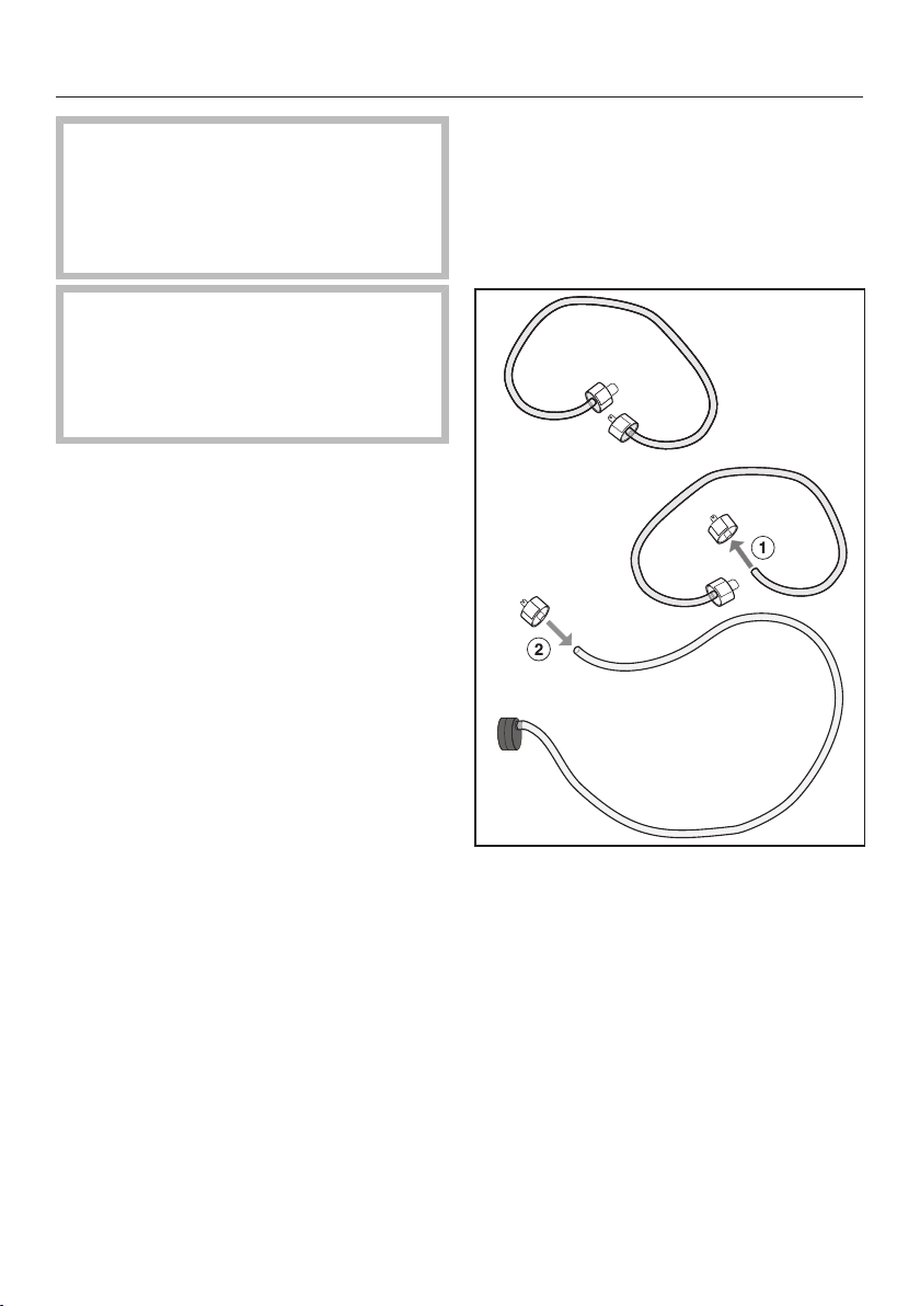
Prepare the vacuum adapter:
Detach the container lid connector
(smaller diameter) from the con-
tainer set connecting tube.
Attach the connector to the end of
the vacuum adapter tube. For a
secure grip, make sure that the end
of the tube is pushed at least
¹/₄" (0.5cm) over the opening on the
connector.
Fill the container to a maximum of
1" (3cm) below the rim.
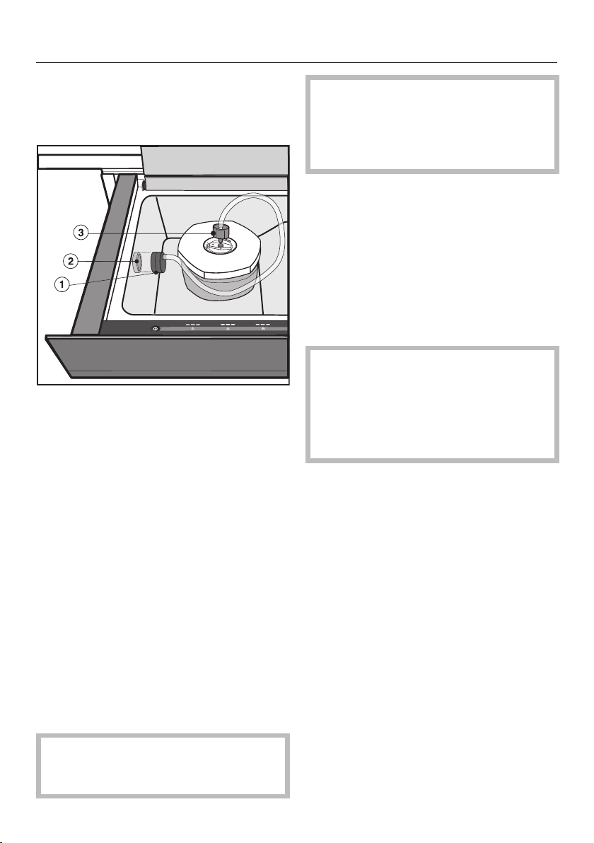
Operation
24
Place the lid on the container and
press it down.
Open the drawer and the glass lid.
Place vacuum adapter over the
vacuum pump air intake valve.
Attach the connector to the con-
tainer lid. Make sure that the closure
of the lid is turned to “seal” (closed).
Switch the drawer on with the sen-
sor.
The and sensors will light up.
Touch the sensor.
The and sensors go out. The
and sensors light up.
Touch the sensor repeatedly until
the segment for the required vacuum
level lights up.
Touch the sensor.
The vacuuming process will start.
Leave the glass lid open for the en-
tire duration of the vacuuming
process.
If an excessive amount of bubbles
form, you can cancel the vacuuming
process by pressing the sensor
(see “Canceling a vacuuming
process”).
After the vacuuming process
An acoustic tone will sound.
Detach the connector from the con-
tainer lid. Make sure that the closure
of the lid is still turned to
“seal” (closed).
Remove the vacuum adapter from the
vacuum pump air intake valve.
Before starting a new vacuuming
process, check that the vacuum
adapter, the tube, and the vacuum
chamber are clean and dry.
Remove any soiling or liquid residues
if necessary.

Operation
25
After use
Touch the sensor to switch the
drawer off.
Clean and dry the drawer and any ac-
cessories as described in “Cleaning
and care”.
Do not close the glass lid until the
vacuum chamber is completely dry.
Close the drawer.
The last vacuum and sealing level se-
lected is automatically activated the
next time the drawer is switched on,
and this is shown in the display.
Canceling a vacuuming
process
You can cancel a vacuuming process at
any time, e.g., if you notice during the
process that the edge of the bag is not
positioned correctly or that the closure
on the container lid is not pointing to
“seal” (closed).
Please note that if the vacuuming
process is canceled when vacuum-
ing bags, the bag will not be sealed.
Touch the sensor.
The vacuuming process stops.

Cleaning and care
26
Risk of injury!
The steam from a steam cleaner
could reach electrical components
and cause a short circuit.
Do not use a steam cleaner to clean
the drawer.
The use of unsuitable cleaning
agents can cause the surfaces to
discolor or alter. Only use cleaning
agents designed for domestic use.
All surfaces are susceptible to
scratching. Scratches on glass sur-
faces could cause a breakage in cer-
tain circumstances.
Remove any residual cleaning agent
immediately.
Allow the sealing bar to cool before
cleaning it.
Switch the drawer off to clean it.
The drawer and accessories should
be cleaned and dried thoroughly after
each use.
Do not close the glass lid until the
vacuum chamber is completely dry.
Unsuitable cleaning agents
To avoid damaging the surfaces, do not
use:
– cleaning agents containing soda, am-
monia, acids, or chlorides,
– cleaning agents containing descaling
agents,
– abrasive cleaning agents, e.g., pow-
der cleaners and cream cleaners,
– solvent-based cleaning agents,
– stainless-steel cleaning agents,
– cleaning agents for ceramic hobs,
– dishwasher cleaner,
– oven cleaners or sprays,
– hard, abrasive sponges and brushes,
e.g., pot scourers,
– sharp metal tools.

Cleaning and care
27
If soiling is left on for any length of
time, it may become impossible to
remove.
Surfaces may suffer discoloration or
damage.
Soiling is best removed after each
use.
Cleaning the drawer front and
glass lid
Remove soiling and fingerprints with
a standard domestic glass cleaner or
with a clean, damp microfiber cloth.
Then wipe the surfaces dry using a
soft cloth.
Cleaning the vacuum chamber
and sealing bar
Do not damage the drawer!
If liquid gets into the vacuum pump
air intake valve, this can result in
damage to the vacuum pump.
Ensure that water does not get into
the air intake valve.
Tip: The sealing bar can be lifted off to
make cleaning easier.
Remove light soiling immediately us-
ing a solution of hot water and liquid
dish soap applied with a clean
sponge or use a clean, damp mi-
crofiber cloth.
Remove any residual cleaning agent
with a little clean water.
Then wipe the surfaces dry using a
soft cloth.
Cleaning the vacuum adapter
Clean the vacuum adapter with a
clean sponge and a solution of hot
water and liquid dish soap or a clean,
damp microfiber cloth.
Then dry the vacuum adapter thor-
oughly with a soft cloth.
Do not use the vacuum adapter again
until it is completely dry.
Cleaning and care
28
Completing a drying cycle
When food is vacuumed, moisture gets
into the oil circulation system in the
vacuum pump. To remove the moisture,
it is necessary to run a drying cycle af-
ter a particular operating period.
The sensor on the control panel of
the drawer lights up yellow when a dry-
ing cycle needs to be carried out. You
can still run another 10vacuuming pro-
cesses after it lights up for the first time.
After that, the sensor lights up red
and a drying cycle must be carried out.
The drawer will lock after the last re-
maining use and cannot be used again
until drying has been carried out.
We recommend carrying out a drying
cycle before the drawer locks out.
The whole drying cycle lasts for a maxi-
mum of 20minutes.
When carrying out the drying cycle,
the vacuum chamber must be empty
and free from liquid residues.
Clean and dry the vacuum chamber
as necessary.
Touch the sensor.
Close the glass lid.
The drying cycle starts. The sensor
will flash yellow throughout the entire
process.
You can cancel the drying cycle with
the sensor. If a drying cycle is
canceled, it must be repeated after the
remaining vacuuming processes have
elapsed or when the drawer is
switched on again.
When the drying cycle has finished, a
buzzer will sound and the sensor
goes out. You can now use the drawer
again as usual.
Frequently Asked Questions
29
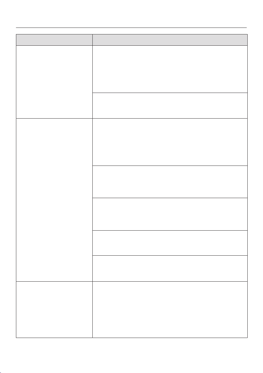
With the help of the following guide minor faults in the performance of the ma-
chine, some of which may result from incorrect operation, can be remedied with-
out contacting the Service Department. Time and money will be saved because a
service call will not be needed.
This guide may help you to find the reason for the fault, and how to correct it.
Problem Possible cause and solution
The drawer will not
open.
The safety screws on the back of the drawer have not
been removed.
Contact Miele Technical Service.
The drawer cannot be
switched on.
The appliance is not correctly plugged in and
switched on at the line power socket.
Insert the plug and switch on at the socket.
The fuse is defective or has tripped.
Reset the trip switch in the line power fuse box
(minimum fuse rating – see data plate). If, after re-
setting the trip switch or replacing the fuse in the
line power fuse box and switching the drawer back
on, the drawer will still not operate, contact a qual-
ified electrician or Miele Technical Service.
There was a loud bang
during operation.
The transit device has not been not removed and the
air filter has not been fitted.
Contact Miele Technical Service.
The drawer has
switched itself off.
The drawer will switch itself off automatically to save
energy if no other action is taken within a certain time
frame after switching it on or after the end of a vacu-
uming process.
Switch the drawer back on.
The sensors are not re-
acting to touch.
Foreign objects, soiling, or liquid residues have got
onto the control panel.
Remove the objects and/or clean the control
panel.
Frequently Asked Questions
30
Problem Possible cause and solution
The vacuuming process
takes longer than ex-
pected.
The oil in the vacuum pump has become extremely
hot.
Leave the drawer to cool for an hour before start-
ing another vacuuming process.
When carrying out a number of consecutive vacu-
uming processes, wait a minimum of 2minutes
between each process to prevent the oil from
overheating again.
The vacuum-sealing
bag was not sealed in
time.
The required vacuum (vacuum level 1) for sealing a
bag was not achieved.
Touch the sensor again or repeatedly until the
vacuuming process ends and the bag is sealed.
All sensors have gone
out. The glass lid will
not open.
There was an interruption to the power supply during
the vacuuming process. The vacuum chamber is still
under pressure so the glass lid cannot be opened.
Do not under any circumstances try to force the
glass lid open or use tools to open it.
When the power supply is restored, the glass lid
can be opened again after initialization (all sensors
and controls light up).
Start the vacuuming process again if necessary.
There is still too much
air in the bag at the end
of the vacuuming
process.
The vacuum level was too low.
Start the vacuuming process again with a new bag
and a higher vacuum level.
The vacuum-sealing bag is too big for the food to be
vacuumed.
Use a new smaller bag or cut a larger bag to fit the
size of the food.
Start the vacuuming process again, with a higher
vacuum level if necessary.
After several consecu-
tive vacuuming pro-
cesses the weld seam
is faulty/not properly
sealed.
The sealing bar has overheated.
Wait a minimum of 2minutes between individual
vacuuming processes to prevent the sealing bar
from overheating again.
Frequently Asked Questions
31
Problem Possible cause and solution
The edge of the bag is
not completely sealed.
The edge of the bag was not positioned centrally
along the sealing bar or has slipped.
Place the edge of the bag centrally along the seal-
ing bar. Make sure that the edge of the bag is par-
allel to the sealing bar and protrudes over it by ap-
prox. ³/₄" (2cm).
The bag is wider than 9 ³/₄" (25cm).
Use vacuum-sealing bags with a maximum width
of 9 ³/₄" (25cm).
The seal was not strong
enough and has
opened.
The edge of the bag is dirty (inside and out). For a
perfect weld seam, the edge of the bag must be dry
and grease-free in the area of the seam.
Fold the edges of the vacuum-sealing bag outward
for filling. This will give you a clean, perfect weld
seam.
The edge of the bag was not positioned smoothly and
without creases on the sealing bar.
Position the bag smoothly and without creases
along the sealing bar.
The sealing level was too low.
Start the vacuuming process again with a new
vacuum-sealing bag and select a higher sealing
level.
The rubber on the counterpressure bar is not evenly
fitted.
Flatten the rubber.
The sealing bar and/or the counterpressure bar is
damaged.
Contact Miele to have it replaced.
The bag is not maintain-
ing the vacuum even
though the weld seam
is intact.
The vacuum-sealing bag has been damaged by sharp
pointed objects, e.g., pointed pasta shapes or a
bone.
Start the vacuuming process again with a new
vacuum-sealing bag, on a lower vacuum level if
necessary.
Use a third-party container if possible.
Frequently Asked Questions
32
Problem Possible cause and solution
The weld seam is de-
fective or not properly
sealed in one or more
places.
The sealing bar and/or counterpressure bar are dirty
or there are liquid residues on the sealing bar.
Clean and dry the sealing bar and/or counterpres-
sure bar.
The rubber on the counterpressure bar is not evenly
fitted.
Flatten the rubber.
The edge of the bag is dirty (inside and out). For a
perfect weld seam, the edge of the bag must be dry
and grease-free in the area of the seam.
Fold the edges of the vacuum-sealing bag outward
for filling. This will give you a clean, perfect weld
seam.
The edge of the bag was not positioned smoothly and
without creases on the sealing bar.
Position the bag smoothly and without creases
along the sealing bar.
The sensor is lit up
even though a drying
cycle has been carried
out. The drawer cannot
be used.
The drying cycle failed to remove all of the moisture
from the oil circulation system in the vacuum pump.
The drawer is locked and cannot be used for 1hour.
Carry out a further drying cycle after 1hour (see
“Cleaning and care – Completing a drying cycle”).
Make sure that the vacuum chamber is free from
liquid residues.
The sensor lights up
yellow. The vacuum is
lower than usual.
Moisture from the food vacuuming process has got
into the oil circulation system in the vacuum pump.
This can result in a reduced level of vacuuming per-
formance.
Carry out a drying cycle (see “Cleaning and care –
Completing a drying cycle”).
The sensor lights up
red. A vacuuming
process cannot be
started.
Moisture from the food vacuuming process has got
into the oil circulation system in the vacuum pump. If
the sensor lights up red, the drawer is locked for
further use.
Carry out a drying cycle (see “Cleaning and care –
Completing a drying cycle”).
Frequently Asked Questions
33
Problem Possible cause and solution
There is a film of oil on
the glass lid and in the
drawer.
The oil in the vacuum pump has become extremely
hot.
Clean the drawer and leave it to cool down for
1hour before starting another vacuuming process.
When carrying out a number of consecutive vacu-
uming processes, wait a minimum of 2minutes
between each process to prevent the oil from
overheating again.
If the fault occurs again, contact Miele Technical
Service.
The vacuuming process
is canceled after 2min-
utes. An acoustic tone
sounds and the sym-
bol lights up red.
The required vacuum could not be achieved.
Switch the drawer off and back on again.
Start the vacuuming process again, selecting a dif-
ferent vacuum level if necessary.
After intensive use of the drawer, the oil in the vacuum
pump has severely overheated.
Leave the drawer to cool for an hour before start-
ing another vacuuming process.
When carrying out a number of consecutive vacu-
uming processes, wait a minimum of 2minutes
between each process to prevent the oil from
overheating again.
The vacuuming process
is canceled after 5sec-
onds. An acoustic tone
sounds and the sym-
bol lights up red.
The glass lid is not sitting evenly. There is an object,
e.g., the edge of a bag, or some soiling on the surface
of the chamber seal.
Remove the obstruction and/or the soiling.
Close the glass lid and press it down lightly for ap-
prox. 5seconds.
The chamber seal is not fitted correctly.
Press the chamber seal in all the way round to
make sure it is fitted evenly.
The chamber seal is damaged, e.g., cracks can be
seen.
Contact Miele Technical Service to replace it.

IMPORTANT SAFETY INSTRUCTIONS - INSTALLATION
34
WARNING - Read all in-
structions before installation or
use of the drawer to prevent
injury and machine damage.
Before connecting the drawer
to the line power supply, ensure
that the connection data on the
data plate (voltage and fre-
quency) match the line power.
This data must correspond in or-
der to avoid the risk of damage
to the drawer. Consult a qualified
electrician if in any doubt.
The electrical outlet must be
easily accessible after the instal-
lation of the drawer.
The drawer may only be built
in combination with those appli-
ances specified by Miele as be-
ing suitable. Miele cannot guar-
antee trouble-free operation if the
appliance is operated in combi-
nation with appliances other than
those quoted by Miele as being
suitable.
The base on which the drawer
and the combination appliance
are fitted must be fixed in place
and must support the weight of
both appliances.
When installing the combina-
tion appliance, it is essential to
follow the instructions given in
the operating and installation in-
structions supplied with it.
The drawer must be installed
in such a way that
– you can see into the vacuum
chamber. This helps to avoid
scalding and burns from
touching the hot sealing bar or
weld seam.
– there is enough space for the
drawer to be pulled out fully
and for opening the glass lid.

Instructions for installation
35
When integrating the drawer with a
combination appliance, the combina-
tion appliance is placed on top of the
drawer without the need for an interim
shelf.
All dimensions in this instruction book-
let are given in mm and inches.
Note to the installer:
Please leave these instructions with the
consumer of the appliance for the local
building inspectors use.
SAVE THESE INSTRUCTIONS.
Installation dimensions
36
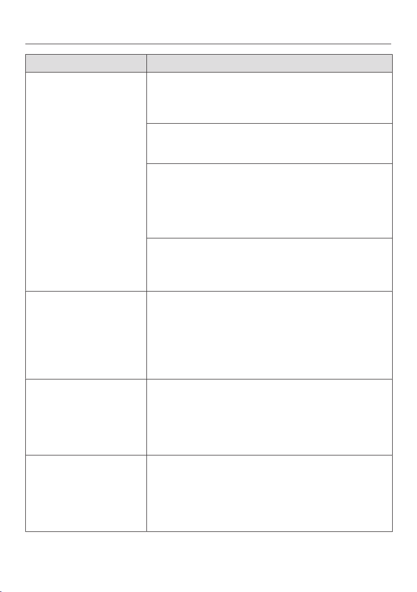
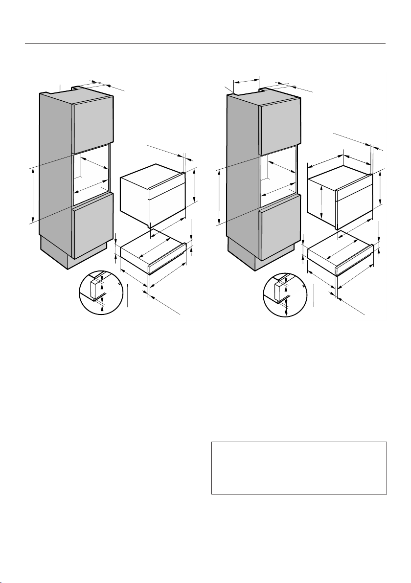
Installation in a base unit
550 mm)
(560 mm - 568 mm)
0(
a
b
c
(4 mm)
3/16"
1/8"
(3 mm)
(141 mm)
23
7/16"
(22*/23**mm)
7/8"
9/16"
9/16"
1/4"
5
5
5
(134 mm)
21
9/16"
(548 mm)
0 21
7/8"
( 29 mm)0
01
1/8"
1/8"
21
(537 mm)
(142 mm)
(595 mm)
22
- 22
3/8"
1/16"
a
Cut-out for ventilation
b
Installation dimensions with plug
Power cord, L = 7' 2" (2,200mm)
c
Countertop overhang
*Glass front / **Stainless steel front
Installation in a tall unit
(141 mm)
a
b
(35 mm)
1
3/8"
(595 mm)
(560 mm - 568 mm)
(142 mm)
5
9/16"
( 550 mm)0
1/8"
21
(537 mm)
(134 mm)
1/4"
5
21
9/16"
(548 mm)
23
7/16"
9/16"
5
(4 mm)
3/16"
1/8"
(3 mm)
7/8"
(22*/23**mm)
22
- 22
3/8"
1/16"
0 21
7/8"
a
Cut-out for ventilation
b
Installation dimensions with plug
Power cord, L =7' 2" (2,200mm)
*Glass front / **Stainless steel front
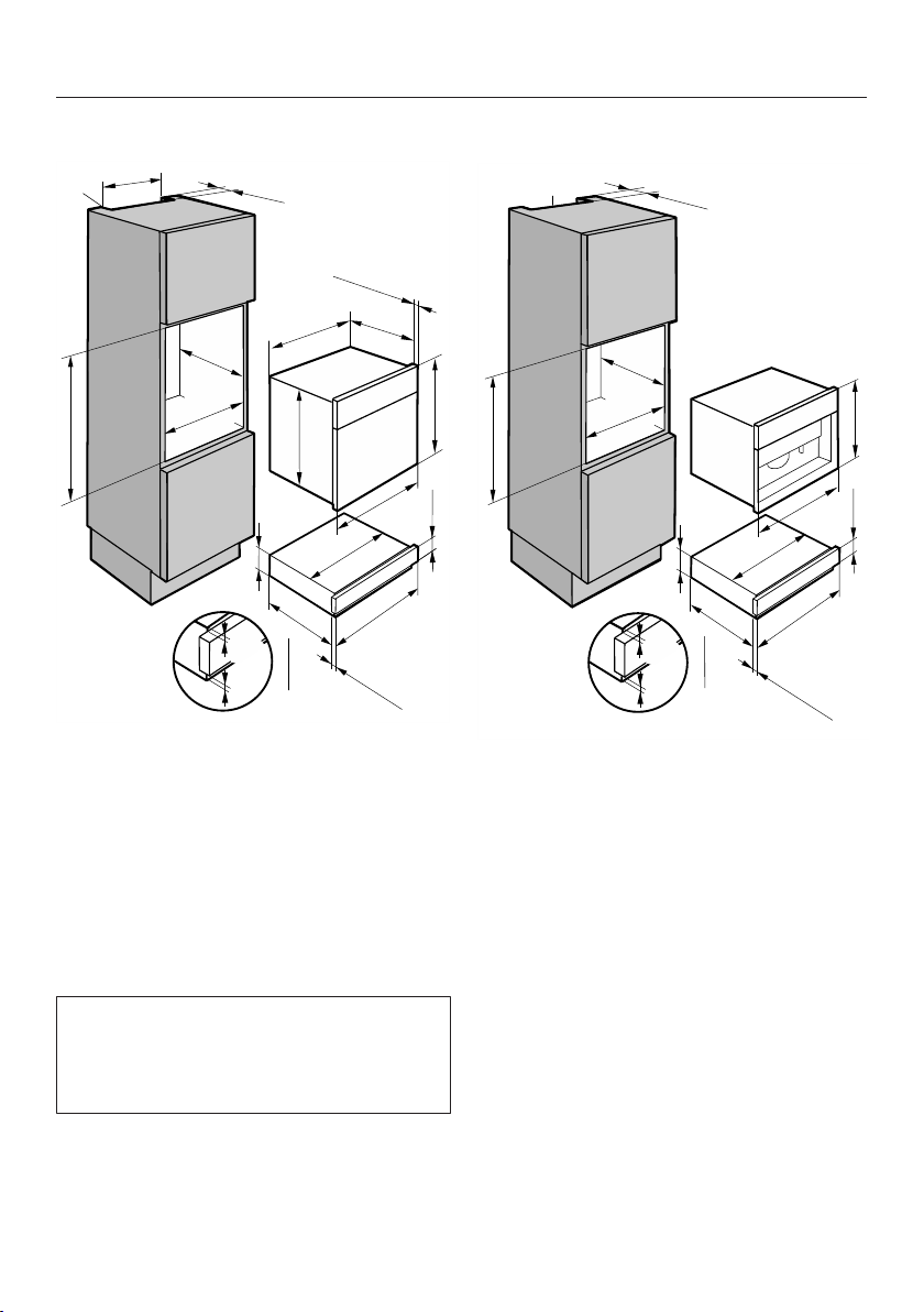
Installation dimensions
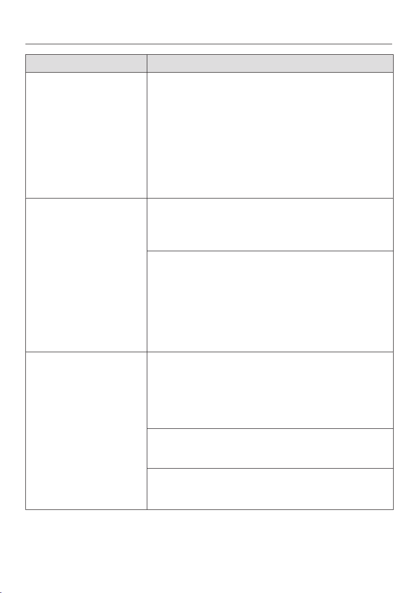
37
EVS with H6xxxB(P)
(734 mm - 736 mm)
a
(596 mm)
23
7/16"
7/16"
(595 mm)
(548 mm)
(141 mm)
(134 mm)
(537 mm)
(595 mm)
(4 mm)
1/4"
5
23
21
1/8"
23
7/16"
21
9/16"
(22*/23** mm)
7/8"
3/16"
1/8"
(3 mm)
9/16"
5
( 550 mm)0
(560 mm
-568 mm)
22
1/16"
21
7/8"
28
7/8"
- 29"
b
(35 mm)
1
3/8"
- 22
3/8"
(22*/23** mm)
7/8"
a
Ventilation cut-out required when in-
stalled in combination with a Self
Clean oven
b
Installation dimensions including
power cord plug connector
Power cord L = 7'2" (2,200mm)
*Glass front/**metal front
EVS with H6xxxBM / M61xx /
M62xx
(560 mm
-568 mm)
(455,5 mm)
(593 mm - 595 mm)
(595 mm)
(548 mm)
(141 mm)
(537 mm)
(595 mm)
(4 mm)
23
3/8"
- 23
7/16"
22
- 22
3/8"
1/16"
21
17
15/16"
23
7/16"
21
1/8"
23
7/16"
21
9/16"
1/8"
(3 mm)
9/16"
5
(134 mm)
1/4"
5
7/8"
b
a
( 550 mm)0
3/16"
(35 mm)
1
3/8"
(22*/23** mm)
7/8"
(22*/23** mm)
7/8"
a
Ventilation cut-out required when in-
stalled in combination with a Self
Clean oven
b
Installation dimensions including
power cord plug connector
Power cord L = 7'2" (2,200mm)
*Glass front/**metal front
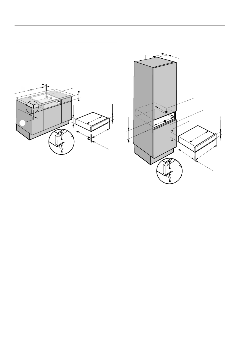
Installation dimensions
38
EVS with DG6x00
(560 mm
-568 mm)
(455,5 mm)
(593 mm - 595 mm)
(595 mm)
(548 mm)
(141 mm)
(537 mm)
(595 mm)
(4 mm)
23
3/8"
- 23
7/16"
22
- 22
3/8"
1/16"
21
17
15/16"
23
7/16"
21
1/8"
23
7/16"
21
9/16"
1/8"
(3 mm)
9/16"
5
(134 mm)
1/4"
5
7/8"
b
a
( 550 mm)0
3/16"
(35 mm)
1
3/8"
(22*/23** mm)
7/8"
(22*/23** mm)
7/8"
a
Ventilation cut-out required when in-
stalled in combination with a steam
oven
b
Installation dimensions including
power cord plug connector
Power cord L = 7'2" (2,200mm)
*Glass front/**metal front
EVS with DGC6x0x
(455,5 mm)
(595 mm)
(141 mm)
(537 mm)
(595 mm)
(449 mm)
17
5/8"
17
15/16"
17
23
7/16"
21
1/8"
23
7/16"
(548 mm)
21
9/16"
(22*/23**mm)
7/8"
9/16"
5
(134 mm)
1/4"
5
(40 mm)
1
9/16"
(550 mm)
21
9/16"
b
(560 mm
-568 mm)
(593 mm - 595 mm)
23
3/8"
- 23
7/16"
22
- 22
3/8"
1/16"
21
7/8"
( 550 mm)0
a
(500mm)
(548 mm)
21
5/8"
22
1/16"
(22*/23** mm)
7/8"
(4 mm)
1/8"
(3 mm)
3/16"
a
Ventilation cut-out required when in-
stalled in combination with a steam
combination oven
b
Installation dimensions including
power cord plug connector
Power cord L = 7'2" (2,200mm)
*Glass front/**metal front
For the DGC 6805, cut-outs are re-
quired for the water inlet and drain
hoses (see DGC 6805 installation in-
structions).
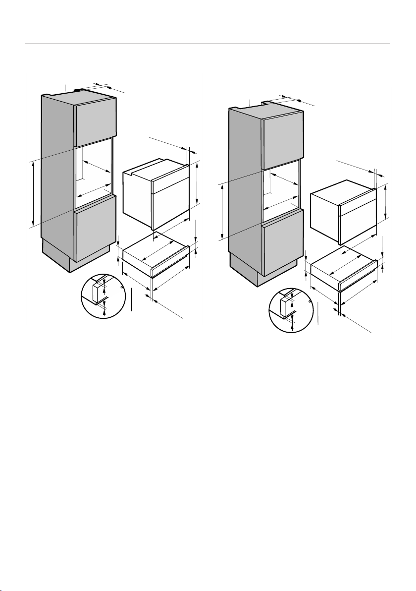
Installation dimensions
39
EVS with DGC6x6x
(734 mm - 736 mm)
(40 mm)
(596 mm)
23
23
7/16"
1/4"
7/16"
(548 mm)
(141 mm)
(134 mm)
(537 mm)
(595 mm)
1/4"
5
23
21
1/8"
23
7/16"
21
9/16"
(22*/23**mm)
7/8"
9/16"
5
0
( 555 mm)
21
7/8"
28
7/8"
- 29"
b
(22*/23** mm)
7/8"
a
(500mm)
9/16"
(590 mm)
(548 mm)
(550 mm)
(595 mm)
21
7/8"
9/16"
21
1
22
1/16"
(560 mm
-568 mm)
22
- 22
3/8"
1/16"
(4 mm)
1/8"
(3 mm)
3/16"
a
Ventilation cut-out required when in-
stalled in combination with a steam
combination oven
b
Installation dimensions including
power cord plug connector
Power cord L = 7'2" (2,200mm)
*Glass front/**metal front
For the DGC 6x65, cut-outs are re-
quired for the water inlet and drain
hoses (see DGC 6x65 installation in-
structions).
EVS with CVA640x / CVA680x
a
(40 mm)
(595 mm)
(548 mm)
(141 mm)
(537 mm)
(595 mm)
23
7/16"
21
1/8"
23
7/16"
21
9/16"
(22*/23** mm)
7/8"
9/16"
5
(134 mm)
1/4"
5
b
(593 mm - 595 mm)
23
3/8"
- 23
7/16"
(455,5 mm)
17
15/16"
1
9/16"
(4 mm)
1/8"
(3 mm)
3/16"
(560 mm
-568 mm)
22
- 22
3/8"
1/16"
21
7/8"
( 550 mm)0
a
Ventilation cut-out for installation in
combination with a coffee machine
b
Installation dimensions including
power cord plug connector
Power cord L = 7'2" (2,200mm)
*Glass front/**metal front
Installation
40
Do not damage the drawer!
The drawer has an integrated vac-
uum pump, which contains oil.
To prevent oil from leaking out, the
drawer must be transported and
stored in a horizontal position only.
Do not tilt the drawer and do not
stand it up on its side.
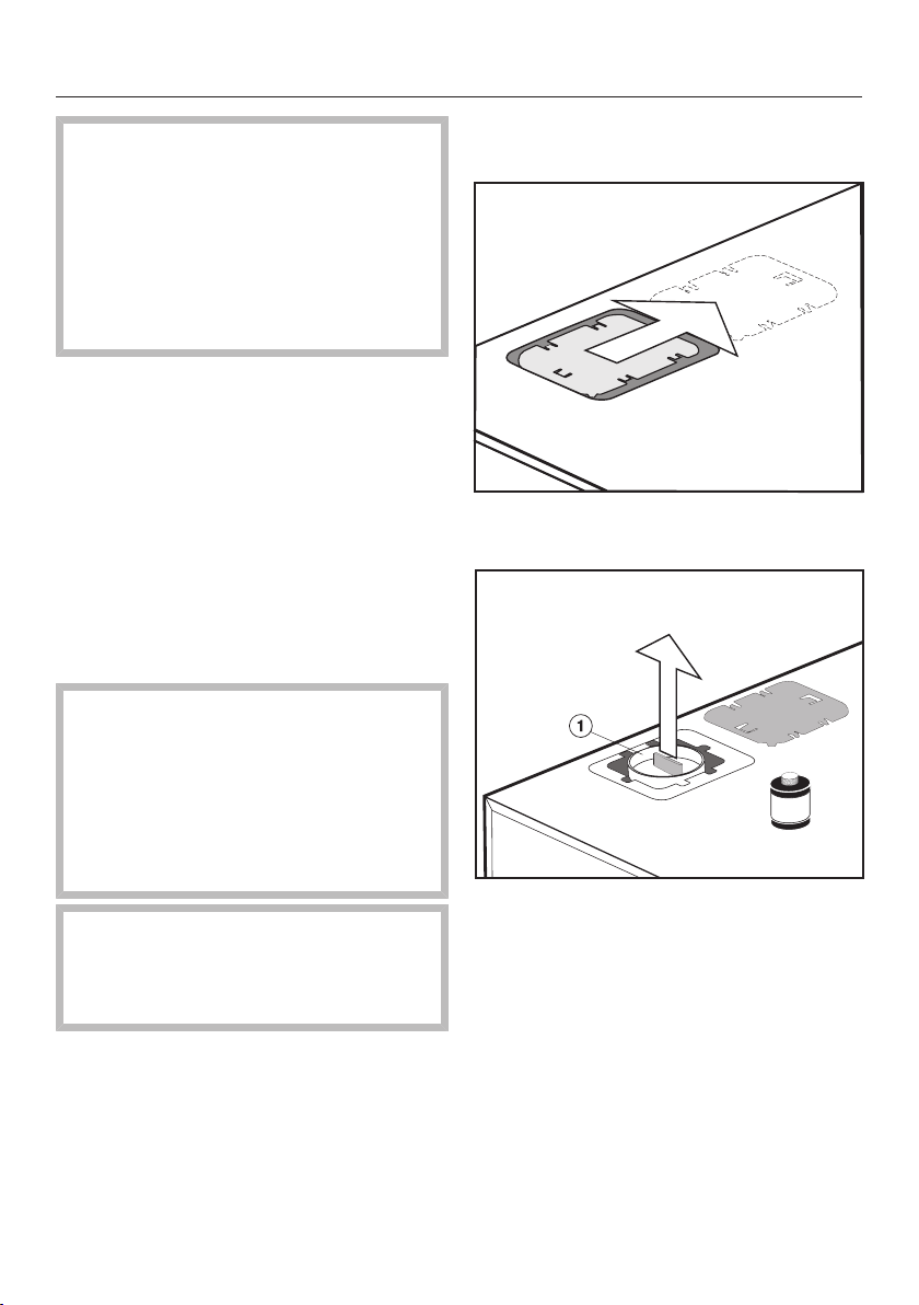
Preparing the drawer
For safe transportation, the vacuum
pump is provided with a transit device
which must be removed before installa-
tion. The air filter supplied must be fit-
ted in place of the transit device.
There are also 2safety screws on the
back of the drawer to prevent the
drawer from being opened unintention-
ally during transportation and when it is
being removed from the packaging.
Warning!
Fit the air filter before integrating the
drawer and remove the safety
screws at the back.
Otherwise, the drawer cannot be op-
erated and may have to be taken out
of the housing unit.
Keep the transit device and safety
screws for any future transportation.
The transit device can be fixed to the
back of the drawer.
Fitting the air filter and removing the
safety screws
Slide the cover to the right and re-
move it.
Pull the red transit device out, e.g.,
with universal pliers.
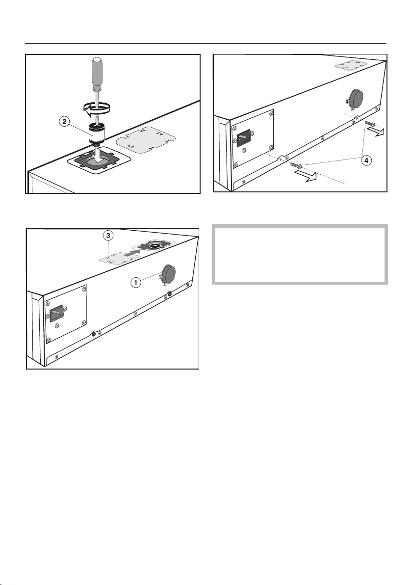
Installation
41
Screw the air filter onto the vac-
uum pump using a screwdriver.
Fix the transit device to the back
of the drawer.
Slide the cover over the opening to
close it.
Remove the safety screws from
the back of the drawer.
Do not damage the drawer!
Remove the air filter before trans-
porting the drawer and plug the vac-
uum pump with the transit device.
To remove the air filter and fit the transit
device, carry out these steps in reverse
order.
Installation
42
Integrating the drawer
Risk of injury!
The drawer is heavy and will tip for-
wards when open.
Installation must be carried out by
two people.
Keep the drawer closed until the
anti-tipping mechanism supplied has
been fitted to the side walls of the
housing unit.
Check that the base that the drawer
will sit on is clean and level (use a
spirit level). This is important for the
appliance to function correctly.
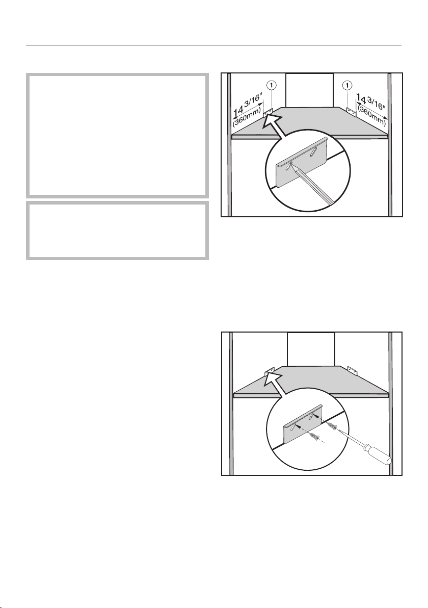
Fitting the anti-tipping mechanism
Measure the distance to the right and
left-hand side walls of the housing
(see illustration).
Mark the uppermost position in the
long slot of the anti-tipping mecha-
nism. Make sure that the anti-tip-
ping mechanism is flush with the
base of the housing unit.
Secure the anti-tipping mechanism to
the right and left-hand side walls of
the housing unit with the 4screws
supplied ³/₁₆" x ⁵/₈" (4x16mm).
Installation
43
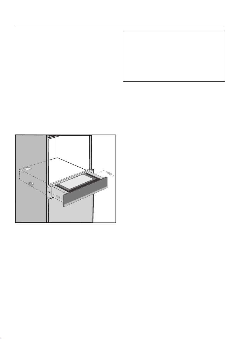
Integrating and connecting the
drawer
Check that the air filter is fitted and
the safety screws have been removed
from the back of the drawer (see
“Preparing the drawer”).
Connect the line power connection
cord to the drawer.
Slide the closed drawer into the
housing unit. When doing so make
sure that the line power cord does
not get trapped or damaged.
Align the drawer at right angles.
Open the drawer and secure it to the
right and left-hand side walls of the
housing unit with the 2wood screws
supplied ¹/₈" x 1" (3.5 x 25 mm).
Remove the 4 foam adhesive labels
from the back of the front panel on
the right and left-hand sides.
Connect the drawer to the line power
supply.
When the drawer is first connected, or
after an interruption of the power sup-
ply, all of the sensors and indicators in
the display will light up for approx.
10seconds for testing (initialization).
As soon as they go out, the drawer is
ready for use.
Integrate the combination appliance
in accordance with the operating and
installation instructions supplied with
it.
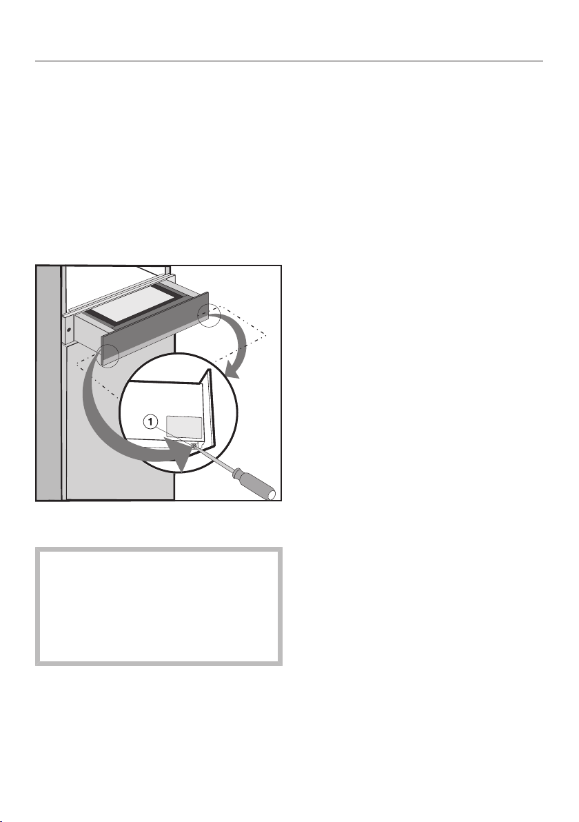
Installation
44
Aligning the front of the drawer
After integrating the combination appli-
ance, it may be necessary under certain
circumstances to align the front of the
drawer and adjust the gap between the
drawer and the combination appliance.
To help you do this, there are 2screws
behind the drawer front with which the
front is fixed to the drawer housing.
Open the drawer.
Loosen fixing screws on the right
and left of the drawer housing.
Danger of injury.
When the fixing screws are removed,
the drawer front is only hooked onto
the housing and can easily fall off.
Do not remove the fixing screws
completely.
Push the drawer up or down a little to
correct the alignment and the gap.
Tighten up the fixing screws.
Electrical connection
45
ATTENTION:
Before installation or servicing, dis-
connect the power supply by either
removing the fuse, manually “trip-
ping” the circuit breaker or unplug-
ging the appliance. Pull the plug not
the cord.
Repairs and service by unqualified
persons could be dangerous and the
manufacturer will not be held re-
sponsible.
Installation work and repairs should
only be performed by a qualified
technician in accordance with all ap-
plicable codes and standards. Instal-
lation, repair, and maintenance work
should only be performed by a
Miele-authorized service technician.
The voltage and frequency listed on
the rating label must correspond with
the household electrical supply to
prevent appliance damage.
Check these data before connection.
Consult an electrician if in doubt.
When another appliance is installed
in combination with the drawer to the
same circuit, operating both appli-
ances at the same time may cause
an overload.
If in doubt consult a qualified electri-
cian.
Installer:
Please leave these instructions with
the customer.
Connection
Make sure that the connection data
on the data plate (voltage, frequency,
and fuse rating) matches that of your
electrical supply.
Connection data
The drawer is ready for connection and
equipped with a 7' 2" (2,200mm) power
cord with a plug.
120V / 15A / 60Hz
Make sure that the connecting socket is
accessible after the installation of the
drawer.

Electrical connection
46
Disconnecting from the power
supply
Danger of electric shock.
After disconnection, ensure the ap-
pliance cannot be switched back on
by mistake.
The drawer must be completely discon-
nected from the power supply during
installation, maintenance and repair
work. This can be ensured as follows:
– The circuit breaker has tripped, or
– The fuse of the electrical installation
is completely removed, or
– The plug (if present) is removed from
the outlet. In the process, pull the
plug not the cord.

Technical Service
47
Contact in case of fault
In the event of a fault which you cannot remedy yourself, please contact your
Miele dealer or Miele Technical Service.
Contact information for Miele Technical Service can be found at the end of this
document.
Please quote the model and serial number of your appliance when contacting
Miele. Both pieces of information can be found on the data plate.
Data plate
Adhere the extra data plate supplied with the appliance in the space below. Make
sure that the model number matches the one specified on the back cover of this
document.
Warranty
For further information, please refer to your warranty booklet.

MieleCare
48
This service is available in USA only.
MieleCare, our Extended Service Con-
tract program, gives you the assurance
of knowing that your appliance invest-
ment is covered by 5years of worry free
ownership.
MieleCare is the only Extended Service
Contract in the industry that guarantees
repairs by a Miele Authorized Service
Provider using genuine Miele parts.
Only genuine Miele parts installed by
factory trained professionals can guar-
antee the safety, reliability, and
longevity of your Miele appliance.
Please note that unless expressly ap-
proved in writing by Miele’s Service de-
partment, Extended Service Contracts
offered by other providers for Miele
products will not be recognized by
Miele. Our goal is to prevent unautho-
rized (and untrained) service personnel
from working on your Miele products,
possibly doing further damage to them,
you and/or your home.
To learn more about MieleCare Ex-
tended Service Contracts, please con-
tact your appliance dealer or visit us
online at:
www.mieleusa.com


9 Independence Way
Princeton, NJ 08540
Phone:
Fax:
www.mieleusa.com
U.S.A.
Miele, Inc.
National Headquarters
Please have the model and serial number
of your appliance available when
contacting Technical Service.
Canada
Importer
Miele Limited
Headquarters and Miele Centre
800-843-7231
609-419-4298
Technical Service & Support
Phone:
Fax:
161 Four Valley Drive
Vaughan, ON L4K 4V8
www.miele.ca
800-999-1360
888-586-8056
Customer Care Centre
Phone:
800-565-6435
905-532-2272
International Headquarters
Miele & Cie. KG
Carl-Miele-Straße 29
33332 Gütersloh
Germany

M.-Nr. 10 927 120 / 02en-US
EVS 6114