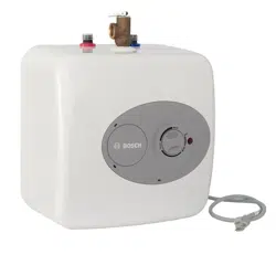
Operating Instructions Water Heater
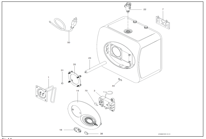
DANGER: Hydrogen gas can be produced in a hot water system served by this heater that has not been used for a long period of time (generally 2 weeks or more). Hydrogen gas is extremely flammable. To reduce the risk of injury under these conditions, it is recommended that the hot water faucet be opened for several minutes at the kitchen sink before using any electrical appliance connected to the hot water system. If hydrogen gas is present, there will probably be an unusual sound such as air escaping through the pipe as the water begins to flow. There should be no smoking or open flame near the faucet at the time it is open.
CAUTION: Any water heater should be installed in such a manner that if it should leak, the resulting flow of water will not cause damage to the area in which it is installed. National Plumbing codes require a drain pan for any water heater installation. Failure to install one is the sole responsibility of owner and/or installer. Reference UPC 2006 (Uniform Plumbing Code) Section 508.1, or IPC 2006 (International Plumbing Code) Section 504.7.
CAUTION: Prior to connecting the power supply, ensure tank is full of water and system is purged of air.
NOTICE: Tank failure due to neglecting to maintain the anode rod is not covered under warranty (see Section 5 Maintenance).
Models overview
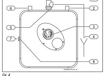
Models ES2.5 and ES4
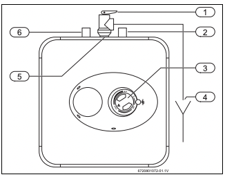
[1] Temperature & pressure relief valve, ¾ NPT male
[2] Cold water inlet ½ NPT male
[3] Thermostat
[4] Temperature & pressure relief valve discharge line to drain
[5] ¾ NPT female tapping for relief valve
[6] Hot water outlet ½ NPT male
Models ES8 (Horizontal installation)
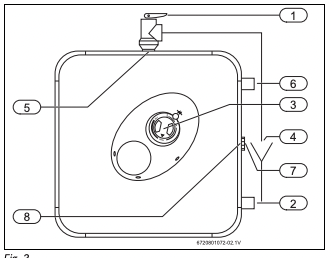
[1] Temperature & pressure relief valve, ¾ NPT male
[2] Cold water inlet ¾ NPT male
[3] Thermostat
[4] Temperature & pressure relief valve discharge line to drain
[5] ¾ NPT female tapping for relief valve
[6] Hot water outlet ¾ NPT male
[7] ¾ NPT male plug
[8] ¾ NPT female tapping for tap
Models ES8 (Vertical installation)
[1] Temperature & pressure relief valve, ¾ NPT male
[2] Cold water inlet ¾ NPT male
[3] Thermostat
[4] Temperature & pressure relief valve discharge line to drain
[5] ¾ NPT female tapping for relief valve
[6] Hot water outlet ¾ NPT male
[7] ¾ NPT male plug
[8] ¾ NPT female tapping for tap
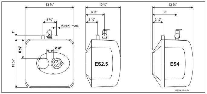
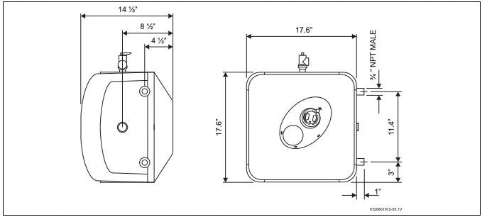
Dimensions
Models ES2.5 and ES4 (Vertical installation only)
Models ES8 (Vertical installation)
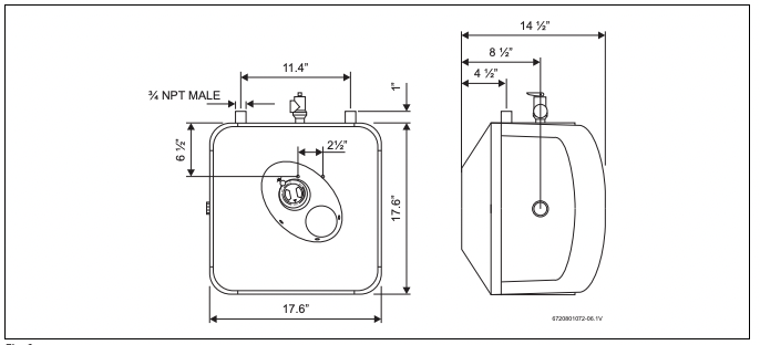
Models ES8 (Horizontal installation)
Installation instructions
 The ES2.5 and ES4 water heaters are designed to be installed under the sink.
Mounting the heater
Wall mounting
- Fasten the supplied mounting bracket to the wall.
NOTICE: Material damages! Use screws that are suitable for the wall material and the weight of the heater.
- Hang the water heater on the bracket.
- Tug down wards on the heater to ensure that both “fingers”of the bracket are seated in the mounting slots.
Floor mounting
Pipe connections
- Connect the cold water inlet pipe to the inlet tapping (marked with a blue ring).
- Ensure a isolation valve is installed on the cold water supply to the water heater.
- Connect the hot water outlet pipe to the outlet tapping (marked with a red ring).
The model ES8 can be piped horizontally from the side or vertically from the top.
Horizontal installation - ES8 Model Only
If you wish to install the unit horizontally, with the piping connections on the right side:
- Install supplied brass plug into tap between hot and cold water connections.
- The supplied Temperature and Pressure Relief Valve will need to be installed on top. See location of T&P relief valve in Fig. 7.
Vertical installation
If you wish to install the unit vertically, with the piping connections on top:
- Install supplied brass plug into tap on side of water heater.
- The supplied Temperature and Pressure Relief Valve will need to be installed on top. See location of T&P relief valve in Fig. 5 and 6.
CAUTION: To reduce the risk of excessive pressures and temperatures in this water heater:
- Install the supplied temperature and pressure protective equipment required by local codes but not less than a combination temperature and pressure relief valve certified by a nationally recognized testing laboratory that maintains periodic inspection of production of listed equipment or materials, as meeting the requirements for Relief Valves and Automatic Gas Shut-off Devices for Hot Water Supply Systems, ANSIZ21.22.
The supplied temperature and pressure relief valve is marked with a maximum set pressure (150 psi) that does not exceed the marked maximum working pressure of the water heater.
- Install the valve in the opening provided and marked for this purpose in the water heater.
- Orient it or provide tubing so that any discharge from the valve will exit within 6 inches above, or at any distance below, the structural floor, and cannot contact any live electrical part. The discharge opening must not be blocked or reduced in size under any circumstances.
National Plumbing codes may require a drain pan for the water heater installation. Failure to install one is the sole responsibility of owner and/ or installer. Reference UPC (Uniform Plumbing Code), or IPC (International Plumbing Code).
Closed system thermal expansion
Periodic discharge of the temperature and pressure relief valve or failure of the element gasket may be due to thermal expansion in a closed water supply system. The water utility supply meter may contain a checkvalve, backflow preventer or waterpressure reducing valve which will create a closed water system.
During the heating cycle of the water heater, the water expands causing pressure inside the water heater to increase. The temperature and pressure relief valve may discharge hot water under these conditions which results in a loss of energy and a build-up of lime on the relief valve seat.
To prevent this from happening, there are two recommendations:
1. Install a diaphragm-type expansion tank that is suitable for potable water on the cold water supply line. A minimum 0.5 gallon expansion tank should be used.
Contact the local water supplier or plumbing inspector for information on how to control this situation. Do not plug the temperature and pressure relief valve.
Use
Electrical connections
The ES8 model must be hard wired. As per the National Electric Code the ES8 needs to be wired with 12 GA. wire to a 20 amp branch circuit.
- Unscrew the junction box cover and remove it.
- Insert 12 AWG through conduit into junction box and secure with conduit strain relief (not supplied).
- Connect the wires and screw on the cover of the junction box.
- Make appropriate wiring connections to the water heater per the National Electric Code.
The unit must be grounded with supplied grounding cable inside junction box.
- Secure junction box cover once wiring connections have been made. When the ES8 is not within sight of the electrical circuit breakers, a circuit breaker lockout or additional local means of disconnection for all non grounded conductors must be provided that is within sight of the appliance. [REF NEC 422.31].
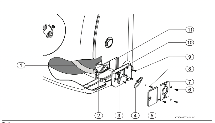
[1] Cable housing (internal to the unit)
[2] Wiring
[3] Protection ring for wiring.
[4] Additional grounding cable AWG16 (minimum length 152mm)
[5] Junction box left cover
[6] Nº3 self tapping screw for junction box covers fixing (with lock washer or serrated head)
[7] Junction box right cover
[8] Nº1 self tapping screw for grounding (with lock washer or serrated head)
[9] Nº4 screws for junction box fixing
[10] Junction box
[11] Housing for junction box (in the plastic front cover)
Use
Starting and testing
CAUTION:
- DO NOT supply power to water heater until filled with water.
To fill the heater:
- Open supply valve for water heater to fill with water.
- Open hot water tap(s) supplied by the water heater to purge air out of the system. Once air is purged, close hot water tap.
- Visually check for any leaks.
Turning heater on
For models which are not fitted with a switch:
- Supply power to the water heater by plugging in the power cord (models ES2.5, ES4) or turning on the circuit breaker (model ES8). If the light does not come on, turn the control knob in a clockwise direction. The light will come on until water temperature has reached the thermostat temperature setting. The light will come back on any time the water temperature inside the tank drops below the thermostat setting
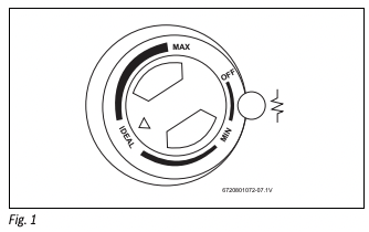
Temperature setting
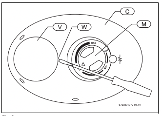
The temperature of the hot water is adjusted by rotating the knob M (Fig. 9) located on the front cover. Temperature range is 65 - 145 °F.
- Turn the knob clockwise to increase temperature.
- Turn the knob counter-clockwise to decrease temperature.
Maintenance
CAUTION: Do not attempt to repair this water heater yourself. Call a service person for assistance. Always turn off the power supply to the heater prior to servicing or draining the heater.
Periodic maintenance
For most of these operations, the water will have to be drained from the heater. For all of these operations the cord should be disconnected (ES2.5 and ES4 only) and the front cover removed.
Removing the cover
- Pry off the round cover plate (Fig. 9, [V]) from its right hand edge (Fig. 9, [W]) with a small flat-head screwdriver.
- Remove the Phillips screw revealed beneath the round cover plate.
- The cover (Fig. 9, [C]) can now be removed by pulling out its lefthand edge. When reassembling, work in the opposite way being careful to insert the tongue of the cover into the slot.
Draining the heater
If the heater has been installed with flexible hoses:
- Shut off the power supply.
- Turn the heater upside down over a sink to drain the water out of it.
-or
it can also be emptied by:
- Siphon through the inlet side hose.
- Keep a hot water faucet open while siphoning.
-or
If the heater has been installed with rigid piping:
- Siphon the water out through any (lower) service valve on the (inlet side).
- Keep a hot water faucet open while siphoning the water out.
Inspecting the anode rod
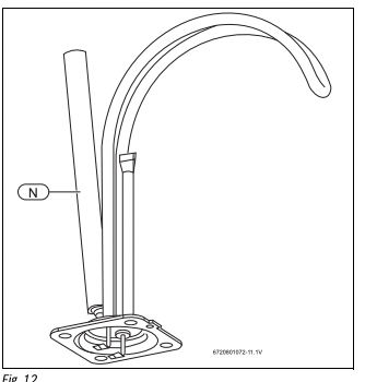
The purpose of the anode rod (Fig. 12, [N]) is to protect the tank against corrosion. It is critical that the anode rod be inspected once a year to determine whether it requires replacement. To access the anode rod, the heating element must be removed (see Section 5.4 Removing the heating element). Upon inspection, the anode rod surface should appear smooth. If the rod surface appears pitted, bumpy, rusty, or if the rod is missing completely, then it must be replaced.
To access the anode rod:
- Remove the heating element (see Section 5.4 Removing the heating element).
Original anode rod sizes
• ES2.5, ES4: length 6½ ”, diameter 5/8”
• ES8:length 8¼ ”, diameter 5/8”
Certain installations may require more frequent replacement of the anode rod:
• recirculation applications;
• poor water quality;
• galvanic/electrolytic corrosion
• high flow applications
In the event of poor water quality, Bosch recommends consulting a local water treatment professional for water treatment options. Always ensure the water heater is grounded. Models ES2.5 and ES4 must be connected only to a properly grounded outlet. Damage resulting from poor water quality or failure to replace the anode rod is not covered under the manufacturer’s warranty. For additional questions, please call Bosch Technical Service.
Removing the heating element
- Turn off power supply and drain the heater (see previous section).
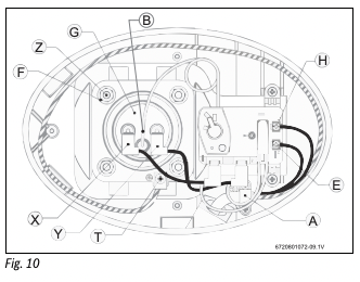
- Remove the front cover plate, disconnect terminals X, Y and T (Fig. 10).
- Unscrew the 4 heating element retaining nuts F (Fig. 10).
- Remove thermostat temperature sensor from well [B] located on the element assembly (Fig. 10).
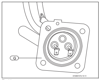
- Remove the element G (Fig. 11).
Replacement of parts
Descaling the heating element
Scale deposits can affect the heating capability of the element. Heavy scale can even cause damage to the element. The element can be descaled either chemically or manually:
- Soak the element in white vinegar or other descaling solution.
- Once descaled, rinse well with fresh water, to which you should add some baking soda,
-or-
- Once the element has dried, use a soft brush (non metallic to prevent damaging the stainless steel sheath) on element.
- Brush the dried mineral off.
- Reinstall the element with gasket and make the wire connections.
NOTICE: Make sure the tank has been refilled with water before restoring power.
Changing the anode rod
- Turn off the power supply and drain the heater (see Draining the Heater).
- Remove heating element (see previous section).
- Unscrew anode rod from threaded connection.
- Remove and replace the anode rod (Fig. 12, [N]).
- Reinstall heating element.
- Refill tank with water before restoring power
Changing the heating element
- Turn off power supply and drain the heater (see Draining the Heater).
- Remove the heating element (see section on Removing the Heating Element).
- Install new element with gasket, making sure the gasket and element are positioned correctly. Tighten the retaining nuts and make the wire connections.
- Ensure that the thermostat temperature sensor is inserted into the well located on the element assembly and secured with black rubber grommet.
- Refill tank with water before restoring power.
Changing the thermostat
- Turn off power supply.
- Disconnect the 2 wire connectors on thermostat.
- Loosen the two brass screws at right side of thermostat and pull wires out.
- Remove thermostat temperature sensor from well located in element assembly.
- Unscrew and remove the two Phillips screws holding the thermostat onto the tank.
- Install new thermostat and re-attach wiring and screws.
- Ensure that the thermostat temperature sensor is inserted into the well located on the element assembly and secured with black rubber grommet.
Troubleshooting
Water does not get hot.
- Make sure the power supply is on and working.
- If light does not come on, check that the high limit reset button is pushed in; follow steps in section 7.1.
- If the indicator light works properly but temperature does not get hot at the tap, test for a plumbing crossover; shut off cold supply to heater and open hot water tap. There should be no water flowing. Any continued flow indicates a crossover which will effect the temperature and will need to be corrected.
- Call a qualified service technician to test the resistance of the heating element (8-10 ohms). Heating element should be replaced if readings are outside these values.
Light not on.
- If the light does not come on, but water gets hot, check for faulty bulb.
- Check high limit reset button; follow steps in section 7.1;
Brown water.
- Brown or rusty water indicates a “spent” anode rod and possible deterioration of the tank body. Inspect the tank for leaks.
- Check anode rod (see section on changing the anode rod).
Odor in water.
- Smelly water could be due to an unusual reaction between local water and the heater’s anode rod. Check anode rod (see section on changing the anode rod).
- Failure to do so may result in damage to the tank and leaks.
Leaking.
- Check water fittings and T & P fitting on top of tank.
- Remove front cover and inspect heating element gasket.
- If tank is leaking call Bosch Water Heating for warranty claim if still within warranty period.
- Check anode rod (see section on changing the anode rod)
Resetting High Limit Switch
Occasionally, the high temperature limit shut off device may trip the reset. This occurs when water temperature exceeds 190 °F. The shut off device may also trigger from a power outage or electrical storm. To reach the thermostat:
- Disconnect power cord (or shut off circuit breaker - model ES8) and remove the front cover.
- Firmly press reset button (Fig. 13, [B]) with the tip of a ball point pen or similar object.
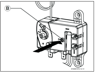
A click indicates the reset was tripped.
IMPORTANT: Check the operation of the thermostat:
- Turn temperature dial from high to low. If the red light does not go off on low setting:
- Turn off power supply and call a service person to replace the thermostat. If the red light does go off the thermostat is working well:
- Place dial setting to desired setting.
A lower setting is more economical and reduces the risk of scalding.
CAUTION: Call a technician if the high limit needs to be reset frequently.
Bosch interior components diagram