INSERT RANGE HOOD
HPB3011-4, HPB3011-6, HPB3019-6, HPB3611-4, HPB3611-6,
HPB3619-6, HPB3619-12 & HPB4819-12 models
INSTALLATION GUIDE
US CA
10505B 02.19

1
EN
1SAFETY AND WARNINGS
!
WARNING!
Weight Hazard
The appliance is heavy. Please ensure adequate care is taken when installing
the appliance to prevent personal injury.
Weight of the products are:
HPB3011-4 = 36lb (17kg)
HPB3011-6 = 36lb (17kg)
HPB3019-6 = 46lb (21kg)
HPB3611-4 = 41lb (19kg)
HPB3611-6 = 41lb (19kg)
HPB3619-6 = 51lb (23kg)
HPB3619-12 = 68lb (31kg)
HPB4819-12 = 77lb (35kg)
!
WARNING!
Electric Shock Hazard
Always disconnect the appliance from the mains power supply before
carrying out any maintenance or repairs.
Installation work and electrical wiring must be done by qualified person(s)
in accordance with all applicable codes and standards, including fire-rated
construction. Failure to do so can result in death, electric shock, fire or injury
topersons.
IMPORTANT!
READ THE ENTIRE SET OF INSTRUCTIONS BEFORE INSTALLING OR USING THIS APPLIANCE.
Refer to the User guide for more details on safety and warnings. A copy of the installation
instruction and user guide for this product can also be found at fisherpaykel.com.
WARNING!
For residential use only.
Use only metal ductwork to reduce the risk of fire.
Do not use flexible ducting.
CAUTION!
Ensure to duct air outside to reduce the risk of fire and to properly exhaust air. Do not vent
exhaust air into spaces within the walls or ceilings or into attics, crawl spaces, or garages.
!
WARNING: Chemical Burn Hazard. Keep batteries away from children.
This product contains a lithium button/coin cell battery. If a new or used lithium button/
coin cell battery is swallowed or enters the body, it can cause severe internal burns
and can lead to death in as little as 2 hours. Always completely secure the battery
compartment. If the battery compartment does not close securely, stop using the product,
remove the batteries, and keep it away from children. If you think batteries might have
been swallowed or placed inside any part of the body, seek immediate medical attention.
Even used cell batteries may cause injury so ensure they are kept away from children and
disposed of properly.
2PRODUCT INFORMATION
IMPORTANT!
SAVE THESE INSTRUCTIONS
The models shown in this installation guide may not be available in all markets and are subject to
change at any time. For current details about model and specification availability in your country,
please go to our website fisherpaykel.com or contact your local Fisher & Paykel dealer.
Other required materials and tools:
Metal ducting
Aluminum tape (DO NOT use duct tape)
T20 head screw driver
1/2” (12.7mm) cULus approved strain relief
1/2” (12.7mm) cULus approved wiring
conduit and connectors
cULus listed wire nuts
Back draft damper(s) if desired
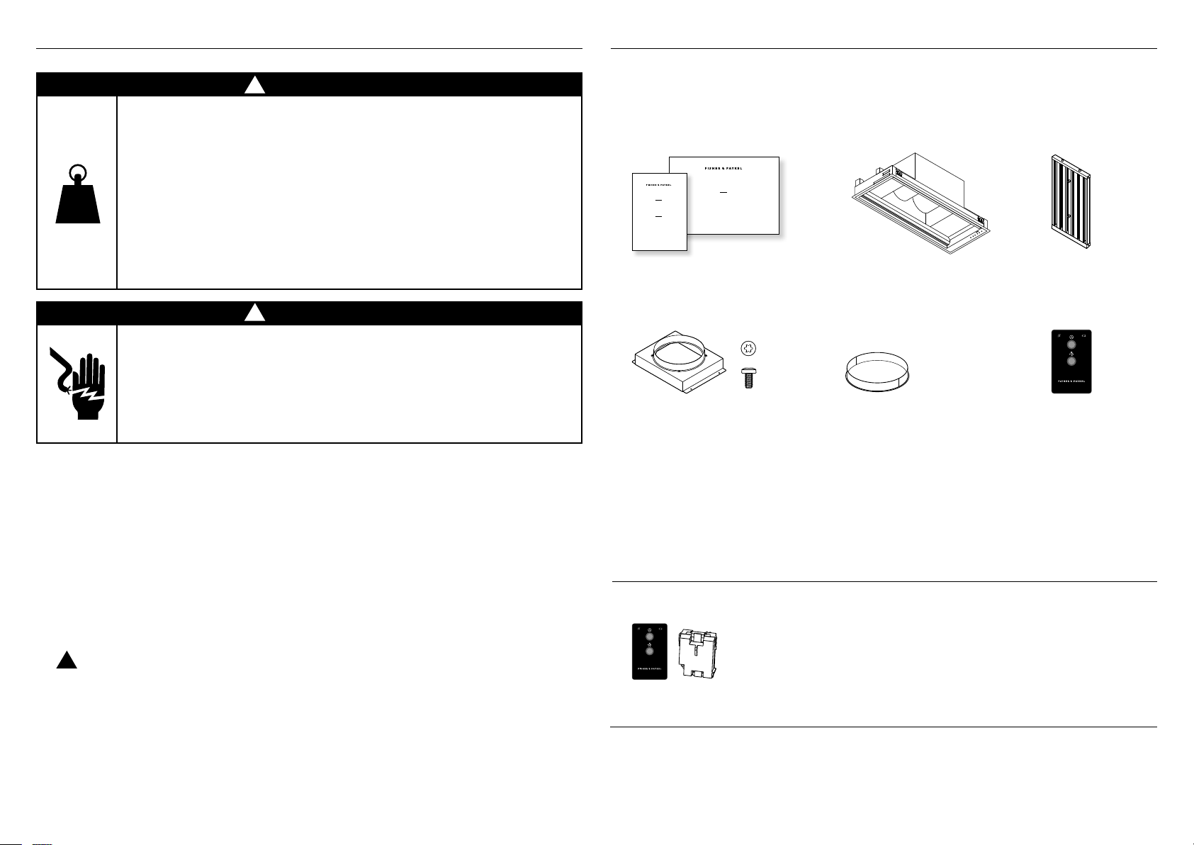
Please read this manual carefully, and keep it after installation for future reference.
Keep all packing materials (box, pallet, straps) until the unit has been inspected.
Inspect the product to check there is no shipping damage. If any damage is detected
contact the dealer or retailer you bought the product from to report the damage.
Fisher & Paykel is not responsible for shipping damage.
User guide and
Installation guide
Range hood Filters
HPB30 (2)
HPB36 (3)
HPB48 (4)
Optional accessories
Remote control kit – Remote control (1),
Wireless receiver (1)
Remote control
(selected models)
¾” OD x 3/16” ID
Flat Washer
#10-32
Pan Head
Pozi Drive
Wall Plug
#8 x 3/4”
Truss Head
Philips Drive
Self Tapping Screw
¼-20 x ½”
Pan Head
Philips Drive
Machine Screw
M4 x8
Pan Head
Torx Drive
Machine Screw
#10x 3”
Countersunk
Pozidrive
Self tapping Screw
FP Pro Hood Fasteners
Duct adaptor including 5/16”
(8mm) T20 drive screws (4)
(selected models)
HPB3619-12, HPB4819-12, have
10” (254mm) outlet
Adaptor ring including 5/16”
(8mm) T20 drive screws (4)
HPB3011-4/6, HPB3019-6,
HPB3611-4/6 and HPB3619-6
have 8’’ (203mm) outlet.
INSERT RANGE HOOD
HPB3011-4, HPB3011-6, HPB3019-6, HPB3611-4, HPB3611-6,
HPB3619-6, HPB3619-12 & HPB4819-12 models
INSTALLATION GUIDE
US CA
105305B 02.19
INSERT RANGE HOOD
HPB3011-4, HPB3011-6, HPB3019-6, HPB3611-4, HPB3611-6,
HPB3619-6, HPB3619-12, HPB4819-12,
HOTTE ENCASTRÉE
Modèles HPB3011-4, HPB3011-6, HPB3019-6, HPB3611-4, HPB3611-6,
HPB3619-6, HPB3619-12, HPB4819-12,
USER GUIDE
GUIDE D’UTILISATION
US CA

3
EN
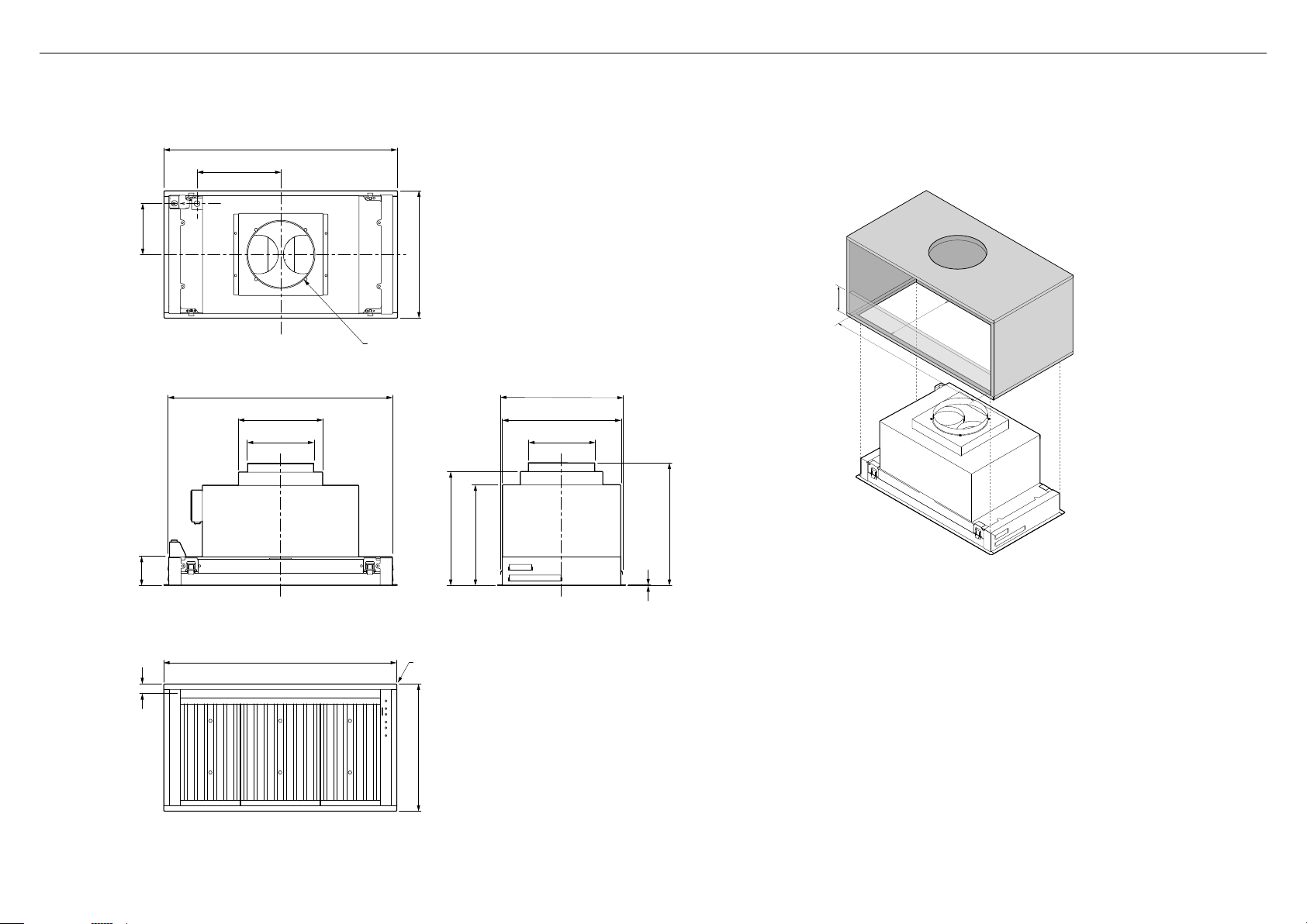
3PRODUCT AND CABINETRY CUT-OUT DIMENSIONS
IMPORTANT!
Actual product dimensions may vary by ± 1/16”(2mm).
Please read the entire instructions before installing the range hood.
HPB3011-4
HPB3011-6 HPB3019-6
HPB3611-4
HPB3611-6 HPB3619-6 HPB3619-12 HPB4819-12
PRODUCT DIMENSIONS inches (mm) inches (mm) inches (mm) inches (mm) inches (mm) inches (mm)
A
Overall height of product 16 1/4 (412) 16 1/4 (412) 16 1/4 (412) 16 1/4 (412) 183/16 (462) 183/16 (462)
B
Overall height of product (excluding duct adaptor) 16 (407) 16 (407) 16 (407) 16 (407) 16 (407) 16 (407)
C
Overall width of product 283/4 (730) 283/4 (730) 345/8 (880) 345/8 (880) 345/8 (880) 467/16 (1180)
D
Overall depth of product 11 (280) 187/8 (480) 11 (280) 187/8 (480) 187/8 (480) 187/8 (480)
E
Thickness of flange 1/16 (2.5) 1/16 (2.5) 1/16 (2.5) 1/16 (2.5) 1/16 (2.5) 1/16 (2.5)
F
Corner radius of flange 1/8 (3.5) 1/8 (3.5) 1/8 (3.5) 1/8 (3.5) 1/8 (3.5) 1/8 (3.5)
G
Width of chassis including louvres 279/16 (700) 279/16 (700) 337/16 (850) 337/16 (850) 337/16 (850) 451/4 (1150)
H
Depth of chasis including mounting feet 103/8 (264) 181/4 (463) 103/8 (264) 181/4 (463) 181/4 (463) 181/4 (463)
I
Depth of chassis excluding mounting feet 915/16 (252) 1713/16 (452) 915/16 (252) 1713/16 (452) 1713/16 (452) 1713/16 (452)
J
Height of side of chassis 43/8 (111) 43/8 (111) 43/8 (111) 43/8 (111) 43/8 (111) 43/8 (111)
K
Width of blower housing 13 (330) 13 (330) 13 (330) 13 (330) 231/4 (590) 231/4 (590)
L
Offset of duct adaptor — forward of center 3/8 (10) 7/8 (23) 3/8 (10)) 7/8 (23) 0 (0) 0 (0)
M
Outside diameter of ducting outlet 81/4 (210) 81/4 (210) 81/4 (210) 81/4 (210) 913/16 (250) 913/16 (250)
N
Width of duct adaptor N/A N/A N/A N/A 123/16 (310) 123/16 (310)
O
Depth of duct adaptor N/A N/A N/A N/A 121/2 (318) 121/2 (318)
P
Distance from center of light to front of product 13/8 (35.5) 13/8 (35.5) 13/8 (35.5) 13/8 (35.5) 13/8 (35.5) 13/8 (35.5)
Q
Height to top surface of duct adaptor N/A N/A N/A N/A 167/8 (428) 167/8 (428)
R
Offset of junction box knockout from center 75/16 (186) 75/16 (186) 75/16 (186) 75/16 (186) 127/16 (316) 127/16 (316)
S
Offset of junction box knockout from center 35/8 (92) 79/16 (192) 35/8 (92) 79/16 (192) 79/16 (192) 79/16 (192)
CABINETRY CUT-OUT DIMENSIONS
U
Overall width of cutout
273/4 (705) 273/4 (705) 3311/16 (855) 3311/16 (855) 3311/16 (855) 451/2 (1155)
V
Overall depth of cutout
101/16 (255) 1715/16 (455) 101/16 (255) 1715/16 (455) 1715/16 (455) 1715/16 (455)
Thickness of cabinetry surface Min 5/8 (16)
Max 1 1/2 (38)
Min 5/8 (16)
Max 1 9/16 (38)
Min 5/8 (16)
Max 1 1/2 (38)
Min 5/8 (16)
Max 1 1/2 (38)
Min 5/8 (16)
Max 1 1/2 (38)
Min 5/8 (16)
Max 1 1/2 (38)
Note:
For the larger models we recommend reinforcing your cabinetry. Please ensure that any reinforcing does not prevent access for servicing.
For optional recessed installation refer to product dimensions for reference.
4
IMPORTANT
The HPB3011-4, HPB3011-6, HPB3611-4 and HPB3611-6 models are not suitable for use
witha high powered professional style cooktops.
Range hood width
The range hood width is recommended to be no less than the width of the cooktop.
A wider range hood can be used to increase the capture area if space is not restricted.
The range hood should ideally be centered above the cooktop for proper performance.
WARNING!
To reduce the risk of fire, use only metal ductwork. Do not use flexible ducting
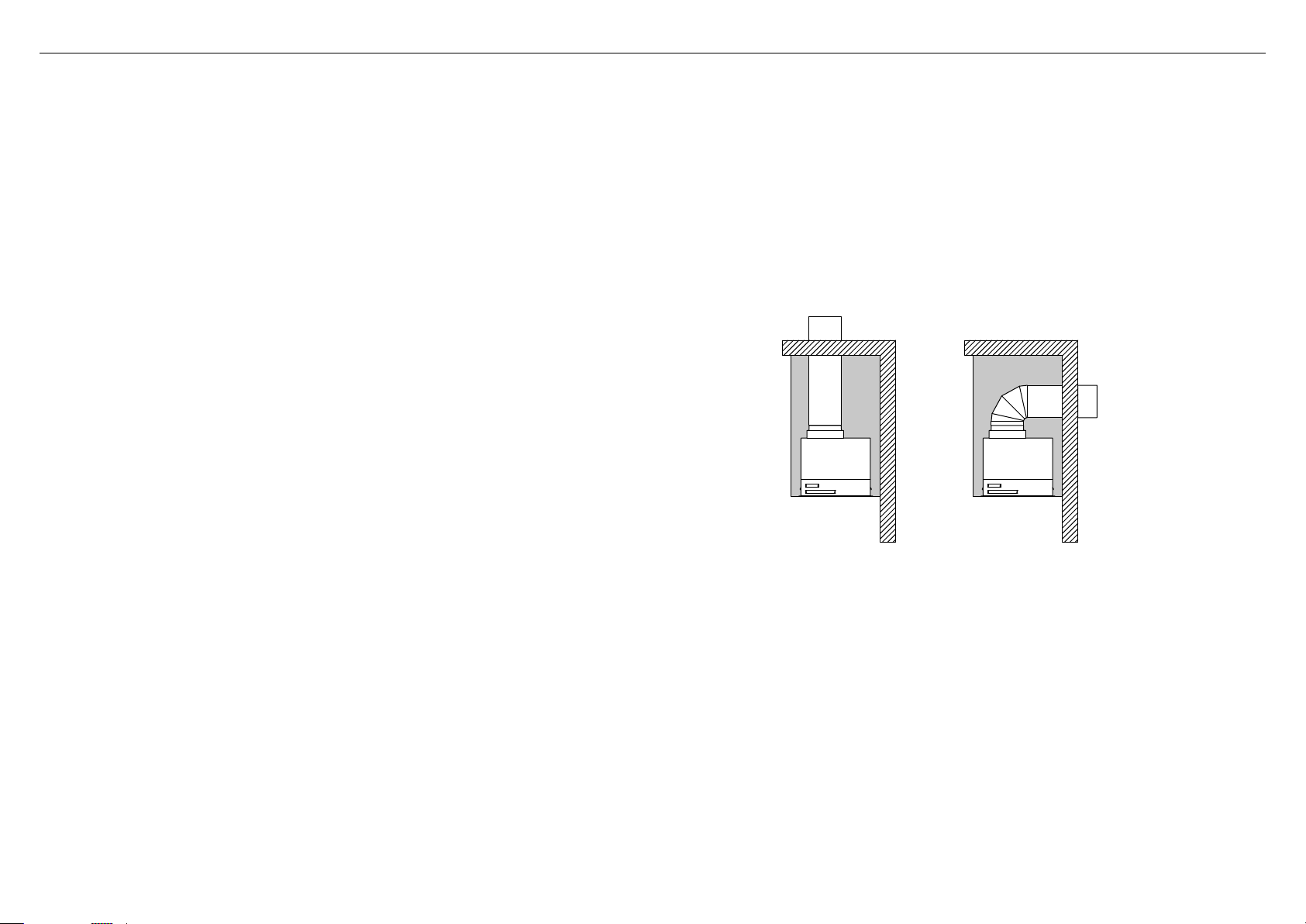
Installation location—Ducting preparation
The range hood is suspended under the cabinetry. The ducting can be configured for
bothvertical and horizontal discharge. The ducting can terminate either through the roof
orwall, to vent through the wall a 90° elbow is needed.
Optional extras
All optional extras must be installed prior to the range hood being installed.
Remote control
If an optional remote control was purchased for installation with the range hood the
remotecontrol receiver must be assembled into the range hood prior to installation.
Installation must be undertaken by an approved service technician. Instructions for
installation are provided with the receiver.
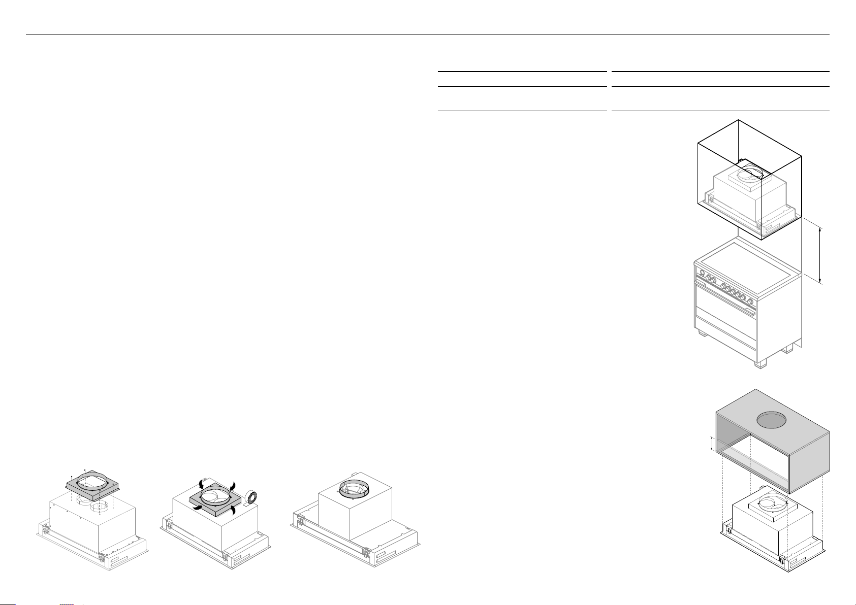
Duct adaptor
A 8” (203mm) or 10” (254mm) round duct adaptor is supplied to mount to the top of
the range hood toprovide a single outlet. This should be installed before the range hood
ismounted.
Duct adaptor assembly
Place the duct adaptor over the range hood exhaust and secure with four 5/16”(8mm)
screws provided (refer to A).
Seal the connection between duct adaptor and range hood with aluminum tape (refer to B).
Note: Double blower models have a adaptor ring as shown below. The assembly steps are
the same as above.
Range hood height
INSTALLATION DIMENSIONS inches (mm)
A
Top of cooking surface to base
ofthe range hood
Minimum 30” (762)
Maximum recommended 42” (1067)
The installation height ranges from a minimum height
of 30”(762mm) to a maximum recommended height
of 42”(1067mm). Consult the cooktop Installation
and User guide for details of the required installation
heightof the range hood.
This range hood must be installed no lower than
the minimum height indicated in the table above.
Minimuminstallation height may be greater if required
by the cooktop manufacturer. Installation at the
minimum height will improve the efficiency of capturing
cooking odors, grease and smoke. Installation at
the maximum recommended height improves user
ergonomics by offering increased head room.
IMPORTANT
Always switch your range hood on when you
arecooking.
Using a powerful gas cooktop or multiple gas burners
operating at the same time can cause the range hood
surfaces to become hot, this effect can be reduced by:
– Using the maximum speed setting to enable hot
air to be extracted quickly.
– Installing the range hood at the maximum
recommended height. Consult the cooktop
Installation and User guide for details on the
installation height of the range hood.
Cabinet mounting installation
The cabinet must be of sufficient strength and
structurallyjoined to the wall studs to support the
weightof this range hood.
If support beams are added to cabinetry these must
notbe more than 11/2”(38mm)
B
high from the
underside of the cabinet. Beams that are higher will
prevent accessfor servicing.
The range hood must be installed into an opening on
theunderside of the cabinet.
Cabinet opening dimensions that are shown must be
used, see ‘Product and cabinetry cut-out dimensions’
section. Given dimensions provide minimum clearance.
We recommend the cupboard has a door or service panel
that can be easily opened to access the power connection.
A
B
A
B
Double blower adaptor: Single blower adaptor:
4INSTALLATION PREPARATION
5
EN
Electrical requirements
WARNING!
Electrical wiring must be done by qualified person(s) in accordance with all applicable
codes and standards.
This unit must be grounded/earthed.
This range hood must be connected with copper wire only.
A 120 volt, 60Hz AC-only electrical supply is required on a dedicated 15A branch circuit.
A time-delay fuse or circuit breaker is recommended.
Wire sizes must conform to the requirements of the National Electrical Code, ANSI/NFPA
70-latest edition, and all local codes and ordinances.
Wire size and connections must conform to the rating of this appliance.
This appliance should be connected directly to the fuse disconnect (or circuit breaker)
through flexible, armored or non-metallic sheathed copper cable. Allow some slack in
thecable so the appliance can be moved if servicing is required.
A cULus listed strain relief or 1/2” (12.7mm) conduit connector must be provided at each
end of the power supply cable (at the appliance and at the junction box).
WARNING!
To reduce the risk of fire or electric shock, do not use this fan with any solid-state
speed control device.
Make-up air (not included)
Attention should be given to ensure that any applicable regulations concerning the
discharge of exhaust air are fulfilled. Local building codes may require the use of
make-up air systems when using ducted ventilation systems greater than specified
cubic feet per minute (CFM) of air movement. The specified CFM varies from locale to
locale. Itistheresponsibility of the owner and the installer to determine if additional
requirements and/or standards apply to specific installations.
Venting requirements
IMPORTANT!
To reduce risk of fire and to properly exhaust air, be sure to duct air outside—Do not vent
exhaust air into spaces within walls or ceilings or into attics, crawl spaces, or garages.
The range hood can be installed to operate with the exhaust air ducted externally from
thekitchen.
Use the shortest and straightest duct route possible, for optimal efficiency.
Elbowsandtransitions increase noise and reduce air flow efficiency.
For best results:
– In ducted installations with internal blowers, use 8” (203mm) or 10” (254mm)
roundducting.
– For inline blowers use 10” (254mm) round ducting.
Vent through roof Vent through exterior wall
Compatible blowers with this range hood
This range hood may only be used with:
The provided internal blowers (for HPB30/36/48 range hood models) and/or
Fisher and Paykel approved Inline blowers which can be purchased separately
(forHP30/36/48 range hood models).
To minimize noise in the kitchen, these blowers are mounted along the duct line
anywherebetween the kitchen and the exterior wall.
CAUTION!
To reduce the risk of fire and electric shock, install this range hood only with remote
blower models rated maximum 4.8A or integral blowers supplied with the range hood.
4INSTALLATION PREPARATION

6
IMPORTANT!
Venting directly into the cabinet with no vent is not permitted.
WARNING!
This appliance is heavy and requires two persons for unpacking and installation.
Installation work and electrical wiring must be done by qualified person(s) in
accordance with all applicable codes and standards.
Failure to install the screws or fixing device in accordance with these instructions
may result in electrical hazards
When cutting or drilling into wall or ceiling, do not damage electrical wiring
andother hidden utilities.
IMPORTANT!
Wear gloves to protect against sharp edges.
The manufacturer is not liable for any damage caused by not following these
instructions.
Before you start installation
Ensure you have read the ‘Installation preparation’ section of this guide.
Unpack the range hood.
Ensure the voltage (V) and the frequency (Hz) indicated on the serial plate match
thevoltage and frequency of the installation site.
Check all functions of the range hood are working.
Check that the area above and behind the installation surface is clear of any electrical
cables or pipes and there is proper clearance for the ducting etc.
The range hood surfaces can be damaged during installation if grazed or knocked
bytools. Please take care to protect the surfaces during installation.
Remove protective wrappings that will not be accessible after installation.
Protect the cooktop to prevent damage occurring whilst the range hood is being
installedabove.
The wall or cabinet used for mounting the range hood should have sufficient
strengthand aflat surface.
WARNING!
Installation work and electrical wiring must be done by qualified person(s) in
accordance with all applicable codes and standards.
This unit must be earthed/grounded. Improper earthing/grounding can result in
arisk of electric shock.
1
Ensure the cabinetry has the required cutout for insertion of the range hood.
Refer to the ‘Cabinetry cutout dimensions’ section of this installation book.
2
If you are using a duct adaptor this must be installed to the range hood prior to the
range hood being mounted. Please refer to ‘Duct adaptor assembly’ for details on
how to install your ductadaptor.
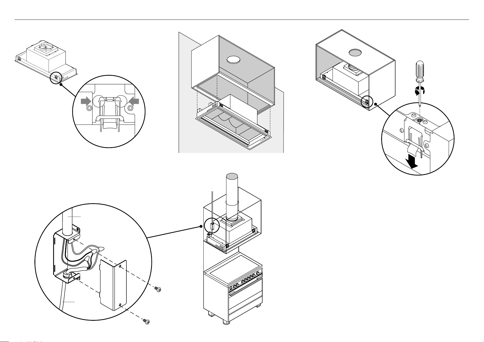
3
Ensure the mounting brackets are set to the correct position for installation by
checking thetop of the foot lines up with the notches (refer to C). Note: Adjusting
the mounting bracket up or down from this position prior to installation could cause
the range hood to be difficult to install and/or damage the cabinetry.
4
Lift the range hood into the opening until the spring loaded mounting brackets click
into place and support the weight of the range hood (refer D). For larger size range
hoods this will require two people. Note: Depending on the cabinetry base panel
thickness the range hood will be protruding below the cabinetry until tightened.
5
Secure the range hood into the cabinetry by tightening each of the mounting
brackets in acounterclockwise direction (refer to E). Tighten each bracket in
succession around the range hood to close the gap incrementally for each bracket.
6
Remove the junction box cover by removing the two screws (refer to F).
7
Remove the electrical knockout and install a cULus listed 1/2” (12.7mm) wiring conduit
and strain relief in the junction box.
8
Run three wires through the conduit from the power supply to the junction box.
9
Connect the power supply wires to the range hood wires using suitable cULus listed
wire nuts:
– black to black
– white to white
– green/yellow to green/yellow
!0
Close the junction box cover and secure with screws.
!1
Complete the installation
Install the filters as described in the ‘Cleaning and maintenance’ section of your
Userguide.
Remove all protective wrapping from range hood.
Turn the power on at control panel.
Check the operation of the range hood as described in the ‘Operating instructions’
section of your User guide.
Refer to G for an image of a completed installation.
5INSTALLATION INSTRUCTIONS
7
EN
Note: The range hood must be installed with
the control panel on the right.
D
C
E
G
DETAIL
B
SCALE 1:5
Power supply conduit
F
From
rangehood
5INSTALLATION INSTRUCTIONS
8
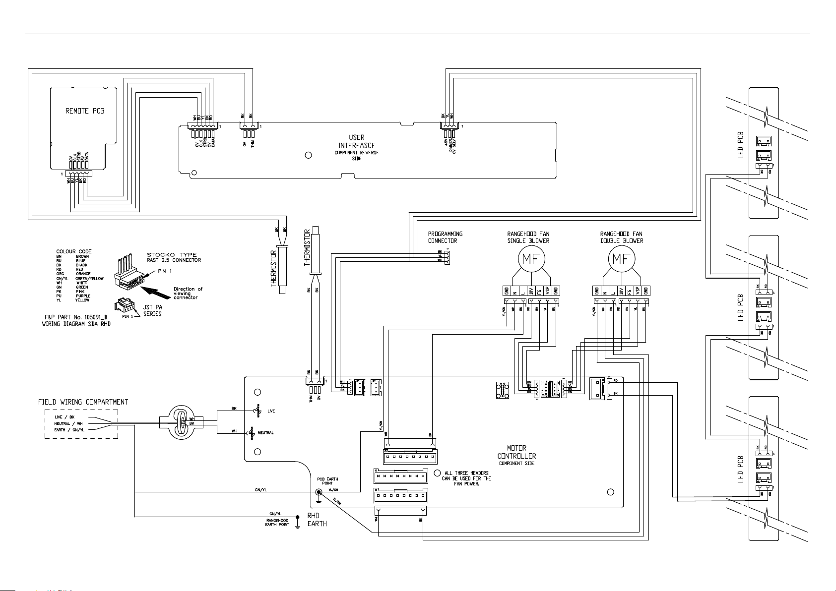
6WIRING DIAGRAM


FISHERPAYKEL.COM
US CA
10505B02.19
© Fisher & Paykel Appliances 2019. All rights reserved.
The product specifications in this document apply to the specific
products and models described at the date of issue. Under our policy
of continuous product improvement, these specifications may change
at any time. You should therefore check with your Dealer to ensure this
booklet correctly describes the product currently available.