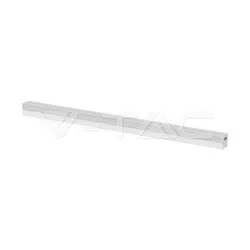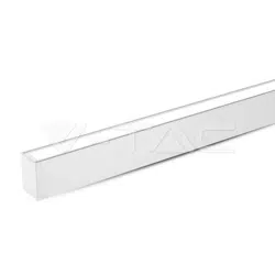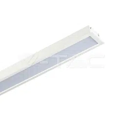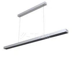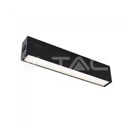
MAGNETIC TRACK
MAGNETIC TRACK ACCESSORIES INSTALLATION
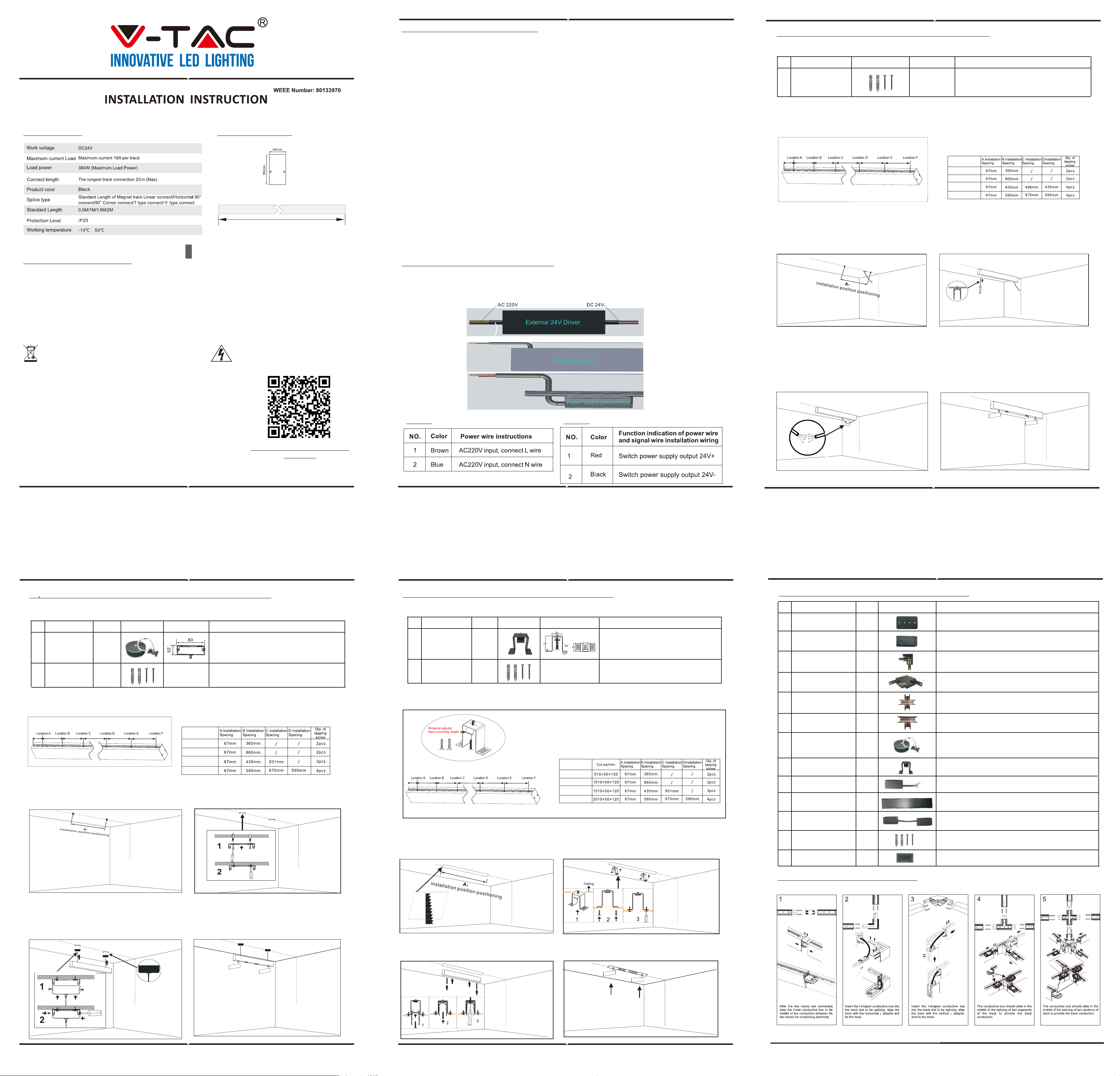
TECHNICAL DATA:
DIMENSION DIAGRAM:
Standard Length of Magnetic Track: 0.5M/1.0M/1.5M/2.0M
INTRODUCTION & WARRANTY
Thank you for selecting and buying V-TAC product. V-TAC will serve you the best. Please read these instructions
carefully before starting the installing and keep this manual handy for future reference. If you have any another
query, please contact our dealer or local vendor from whom you have purchased the product. They are trained
and ready to serve you at the best. The warranty is valid for 3 years from the date of purchase. The warranty
does not apply to damage caused by incorrect installation or abnormal wear and tear. The company gives no
warranty against damage to any surface due to incorrect removal and installation of the product. The products
are suitable for 10-12 Hours Daily operation. Usage of product for 24 Hours a day would void the warranty. This
product is warranted for manufacturing defects only.
IN CASE OF ANY QUERY/ISSUE WITH THE PRODUCT, PLEASE REACH OUT TO US AT: SUPPORT@V-TAC.EU
FOR MORE PRODUCTS RANGE, INQUIRY PLEASE CONTACT OUR DISTRIBUTOR OR NEAREST
DEALERS. V-TAC EUROPE LTD. BULGARIA, PLOVDIV 4000, BUL.L.KARAVELOW 9B
Caution, risk of electric shock.
This marking indicates that this product should
not be disposed of with other household
wastes.
3
YEARS
WARRANTY
*
Surface mounted/Pendant/
Recessed Track(Without wings)
1.Please refer to the track installation diagram for the hole positions(fig 1). And refer to the table below for
dimension spacing of the holes for surface magnetic track.
1. Before you install the pendant track, please refer to the picture of pendant hole diagram (ref fig 6) and
dimension spacing table, then go to the installation area for positioning and installing.
2. Mark hole position and drill holes with tools in the
track installation area. Make sure to drill outlet holes
for power cables (Ref Fig 2).
3. Install the track into the ceiling with self-tapping
screws and the power cord enters through the hole
of the track outlet. Ensure the screw is firmly
installed with the track (Ref Fig 3).
5. Load the magnetic track lights into the track then
switch on the power to test the light (Fig 15).
5. Load the magnetic track lights into the track
then switch on the power to test the light (Fig 10).
5. Load the magnetic track lights into the track then
switch on the power to test the light.
4. Connect the power cables from the track to the
track power connector box, and push the excess
cables into the ceiling from the outlet hole. Please
refer to the installation instructions of the External
power supply installation for wiring connections.
Dimension spacing table of the holes fo surface
magnetic track:
Dimension spacing table of hole for recessed (without
wings)magnetic track
Track installation - Hole position marking diagram
Dimension spacing table for hole of Pendant Magnet track
SURFACE MOUNTED MAGNETIC TRACK INSTALLATION
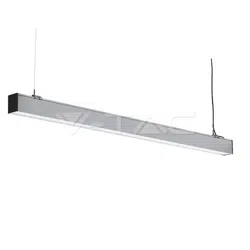
PENDANT TRACK INSTALLATION (SUSPENSION WIRES TYPE)
Accessories required for pendant track installation:
2. In the track installation area, using the tool
mark a straight line and the hole position for
installing the track (Fig 7).
4. Connect the suspension wires with the ceiling box
and track, adjust the suspension wires length as per
the required height, hold the track, and install the
ceiling box and suspension accessories;.Please refer
to the installation instructions of the External
power supply installation for wiring connections.
3. Fix the lifting accessories on the ceiling, check
whether the accessories are firmly installed and
ensure the safely of installation (Fig 8).
Application: Office area, Exhibition hall, exclusive store, hotel, villa , club and other related environment.
2. Before installating please refer to the table for
track cut out size, installation & marking position
(Fig 12).
1. Before you install the recessed track, please refer to the hole position mapping diagram(Fig11), dimension
spacing table of the recessed fixing parts and track cut out size in the installation area.
3. Insert the recessed accessories into the measuring
position on the back of the open ceiling. Fix the fittings
with self-tapping screws and check whether the fittings
are installed correctly. Ensure the track is firmly
installed (Fig 13).
4. Install the track into the ceiling, and fix the track
to the fitting using M7 screws. Ensure the screws
are properly installed (Fig 14).
RECESSED TRACK (WITHOUT WINGS) INSTALLATION
RECESSED ACCESSORY DESCRIPTION:
1. The accessory is mounted on the back of the ceiling board.
2. The thickness of the board should be 8-12mm.
Installation of recessed kit (without
wings) track only. Installation and Fixed
use black.
Recessed Kit
1.
2.
NO
NAME
PICTURE
SIZE
DESCRIPTION
Used for installation/marking of track suspen-
sion line 1.5m (customizable length of suspen-
sion line)
Suspension Wires
For track installation and fixed use.
4x30mm Tapping
Screw
4x30mm
CRI >90
~+
UGR<19
This product is to be installed in indoor location only. Do not install this
lamp on the following locations:
1. Temperature below 10°C and above 50°C;
2. Ceilings that cannot support the weight of the lamp/lantern; Inclined,
concave, or convex ceilings;
3. Wet area with the humidity of >80% PH;
4. Dusty, has presence of corrosive gases;
5. Rooms where magnets are heavily used or altered (operating rooms in
hospitals, etc.)
6. Near the AC system OR Insulated areas OR Near direct sunlight
Note: Please make sure to turn OFF the power before starting the
installation.
SAFETY PRECAUTIONS BEFORE INSTALLATION
MULTI-LANGUAGE MANUAL
QR CODE
Please scan the QR code to access
the manual in multiple languages.
TRACK CONNECTOR INSTALLATION
Track Straight Connector
90° Corner Connector
Outer Corner Connector
T Type Connector
X Type Connectors
FIG 1
FIG 6
FIG 7
FIG 11
FIG 12
FIG 13
FIG 14
FIG 15
FIG 9
FIG 8
FIG 10
FIG 2
FIG 3
FIG 4
FIG 5
Accessories required for surface mounted magnetic track installation:
1.
NO
NAME
PICTURE
SIZE
DESCRIPTION
For track installation and fixed use
4x30mm Tapping
Screw
4x30mm
Accessories required for recessed track(without wings) installation:
1.
2.
NO
NAME SKU
7970
SKU
7977
PICTURE
SIZE
DESCRIPTION
For track installation and fixed use.
4x30mm Tapping
Screw
4x30mm
D
D
D
1 2 3
4 5 6
EXTERNAL POWER SUPPLY INSTALLATION
1.Remove the end cap from one end of track, insert the power terminal box into the track;
2.Put the power supply on the ceiling and wire AC power by brown/blue wire. Take out the DC
wire red/blue from the ceiling and insert in the hole of track, then wire with power terminal box.
Table 2
- Please turn off the Power before starting the installation.
- Installation shall only be done by a certified electrician.
- The magnetic suction track needs to be equipped with a 24V DC switching power supply which cannot be
directly connected to the municipal electricity.
- Lighting and other power lines (such as AC or high-power electric equipment) should be separated or kept at
a distance.
- Before installing/repairing the lamps, make sure that the power supply has been cut off and that the connec-
tion is correct before the power supply is switched on [Risk of electric shock].
- Please do not deconstruct or alter the lamp to prevent risk of electric shock, malfunctions, or any kind of
accident.
- Do not touch the lamp, when the product is switched on/off, the product is high in temperature.
- Do not install the product with wet hands
- There should be no strong alternating magnetic field around the lamp.
- The built-in magnetic structure of the lamp has great magnetic attraction. Please be careful when installing
the track of the lamp to avoid getting injuries.
- The safety buckle should be locked in place when the lamps and lanterns are put on track to avoid risk of
falling lamp.
- The actual power of the product ranges from 90% to 110% of the nominal power. The load current carrying
capacity of the wires should be considered while wiring.
- The force point of the ceiling in the lighting installation area must be more than four times the weight of the
lamp for safety [Risk of falling & failure].
- The lamp can not be used in violation of any fire protection regulation.
- The light source of this luminaire is not replaceable, when the light source reaches its end of life the whole
luminaire should be replaced.
- In the presence of smoke & foul odor, please cut off the power immediately and consult the installation
personnel/electrician.
WARNING! & SAFETY INSTRUCTIONS:
Table 1
NO
1.
2.
3.
4.
5.
6.
7.
8.
9.
10.
11.
12.
13.
NAME
PICTURE
DESCRIPTION
Surface mounted / Pendant / Recessed (without wings)
track horizontal 90° corner splicing
To be used for track straight line splicing, 1PC for each
segment splicing
For vertical track splicing
Surface mounted / Pendant / Recessed (without wings)
track, + type connector splicing only
Only for bright/ lifted/ embedded installation without side
rail T type splicing
Used for installation/ marking of track suspension line 1.5m
(customizable length of suspension line)
Installation of recessed (without wings) track only
Installation and fixed use
Conductive use/ optional purchase for connection
between track line and power supply
Option for Conductive Linear Connection of Track
Conductive use/optional purchase for L type rail
connections
Magnet track PC Cover for track without lamp
For track installation and fixed use
Used for installation of end caps at both ends of tarck
90'D Connector
Outer conner
connector
X connector
T connector
Pendant accessory
Recessed kit
Live end connector
L type track
connector
Track cover
4x30mm Tapping
screw
End cap
SKU
7971
7972
7973
7974
7975
7977
7970
7979
7971
7978
Track connector
set (Metal Plate)
Track connector
set (straight
connector)
SKU/Length
7950 / 0.5M
7951 / 1M
7953 / 1.5M
7952 / 2M
SKU/Length
7950 / 0.5M
7951 / 1M
7953 / 1.5M
7952 / 2M
SKU/Length
7950 / 0.5M
7951 / 1M
7953 / 1.5M
7952 / 2M