SAFETY INFORMATION
WATER TEMPERATURE ADJUSTMENT
- Safety, energy conservation, and hot water capacity are factors to be considered when selecting the water temperature setting of the water heater.
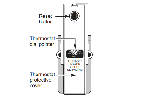
- Water temperatures above 125°F can cause severe burns or death from scalding. Be sure to read and follow the warnings outlined on the label pictured to the left. This label is also located on the water heater near the top of the tank
- Thermostat has been set at the factory to 120°F (49°C) to reduce the risk of scald injury. This is the recommended starting temperature setting, but it can be adjusted to any temperature between 90°F and 150°F (32°C and 66°C).
Water Temperature Setting
- The temperature of the water in the water heater can be regulated by setting the temperature dial of the adjustable surface mounted thermostat(s) located behind the jacket access panel(s). Dual element heaters have 2 thermostats.
- The illustration shows the temperature adjustment dial used for setting the water temperature.
- Refer to the Operating Instructions in this manual for detailed instructions in how to adjust the thermostat(s).
- DANGER Hotter water increases the Potential for Hot Water SCALDS.
SAFETY CONTROLS
- The water heater is equipped with a combination thermostat and high limit Energy-Cut-Off control (ECO) that is located above the heating element in contact with the tank surface.
- If for any reason the water temperature becomes excessively high, the high limit control (ECO) breaks the power circuit to the heating element.
- Once the control opens, it must be reset manually. Resetting of the high limit control should be done by a qualified service technician.
CAUTION
- The cause of the high temperature condition must be investigated by a qualified service technician and corrective action must be taken before placing the water heater in service again.
To reset the temperature-limiting control:
- Turn off the power to the water heater.
- Remove the jacket access panel(s) and insulation.
- The thermostat protective cover should not be removed.
- Press the red RESET button.
- Replace the insulation and jacket access panel(s) before turning on the power to the water heater.
- Ensure water heater is operating properly after resetting the ECO.
OPERATING INSTRUCTIONS
Temperature Setpoint:
- The water heater temperature setting strongly impacts the amount of usable hot water available for showers and baths.
- Safety regulations require a factory setting no greater than 125°F (52°C) for all new water heaters.
- Therefore, if your old water heater was set to a hotter temperature than your new water heater with a factory set setpoint of 120°F (49°C), the new water heater may seem to provide lower capacity than your old water heater. This can be corrected by increasing the temperature setpoint.
- If more hot water capacity is desired, increasing the temperature from 120°F to 135°F (49°C to 57°C) will enable the same tank of hot water to last about longer because less hot water is mixed in at the shower or faucet.
- Increasing the water temperature setpoint may improve the cleaning performance of dishwashers and washing machines.
- The user can adjust the temperature setting to meet their needs. Always read and understand the safety instructions contained in the owner’s manual before adjusting the temperature setpoint.
- If adjustment is necessary...
Turn off the power to the water heater.
- Remove the jacket access panel(s) and insulation exposing the thermostat(s).
- The thermostat protective cover(s) should not be removed.
- Using a small screwdriver, set the thermostat(s) dial pointer(s) to the desired temperature. Adjust the upper and lower thermostats to the same temperature to maximize hot water availability.
- Replace the insulation and jacket access panel(s).
Turn on the power to the water heater.
Mixing Valves
- Mixing valves for reducing point-of-use water temperature by mixing hot and cold water in branch water lines are commercially available. Contact a licensed plumber or the local plumbing authority for further information.
Extended Shutdown Periods
- If the water heater is to remain idle for an extended period of time, the power and water to the appliance should be turned off and the water heater drained to conserve energy and prevent a buildup of dangerous hydrogen gas. This unit has no power button, power can only be shut off at the circuit breaker or disconnect switch.
- The water heater and piping should be drained if they might be subjected to freezing temperatures.
- After a long shutdown period, the water heater’s operation and controls should be checked by qualified service personnel. Make certain the water heater is completely filled again before placing it in operation.
NOTE:
- Refer to the Hydrogen Gas Caution in the
CARE AND CLEANING
Routine Preventive Maintenance
- If the temperature and pressure-relief valve on the hot water heater discharges periodically, this may be due to thermal expansion in a closed water system. Contact the water supplier or your plumbing contractor on how to correct this. Do not plug the relief valve outlet.
- Properly maintained, your water heater will provide years of dependable trouble-free service. It is suggested that the following annual preventive maintenance program be established.
- Inspect Temperature & Pressure Relief Valve.
- Inspect heating elements, ECO, and wiring to each.
- Drain and Flush the water heater tank.
- Anode rod must be removed and inspected.
Temperature and Pressure-Relief Valve:
- Once a year, it is recommended to lift and release the lever handle on the temperature and pressure-relief valve, located on the front-right side of the water heater, to make certain the valve operates freely. Allow several gallons to flush through the discharge line to an open drain.
Heating Elements and ECO:
- Once a year, it is recommended to inspect the heating elements, ECO, and wiring to each. Inspection should be completed by service personnel qualified in electrical appliance repair.
- Most electrical appliances, even when new, make some sound when in operation. If the hissing or singing sound level increases excessively, the electric heating element may require cleaning. Contact a qualified installer or plumber for inspection.
Draining and Flushing the Water Heater
- A water heater’s tank can act as a settling basin for solids suspended in the water. It is therefore not uncommon for hard water deposits to accumulate in the bottom of the tank. To clean the tank of these deposits, it is recommended to drain and flush the water heater tank once a year. To drain the water heater, follow these steps:
- Turn off power to the unit. The electric heating elements will become damaged if operated without water.
- Attach a garden hose to the drain valve located at the bottom of the unit and direct that hose to a drain.
- Turn off the cold water supply.
- Admit air to the tank by opening a hot water faucet or lifting the handle on the relief valve.
- Open the drain valve.

Flushing the Tank:
1. Follow steps above to drain the water heater.
2. Once the water heater is empty, with the drain valve open and garden hose attached to the drain valve, turn on the cold water supply.
3. Allow several gallons to flush through the drain valve and hose to an open drain.
4. Turn off the water supply and allow any water remaining in the tank to drain.
5. Repeat steps 3 and 4 until water runs clear.
6. Close the drain valve and fill the tank before returning power to the unit. The tank is full when water runs out of a nearby open hot water faucet. Flushing should be done with an empty tank to promote additional removal of sediment.
NOTE:
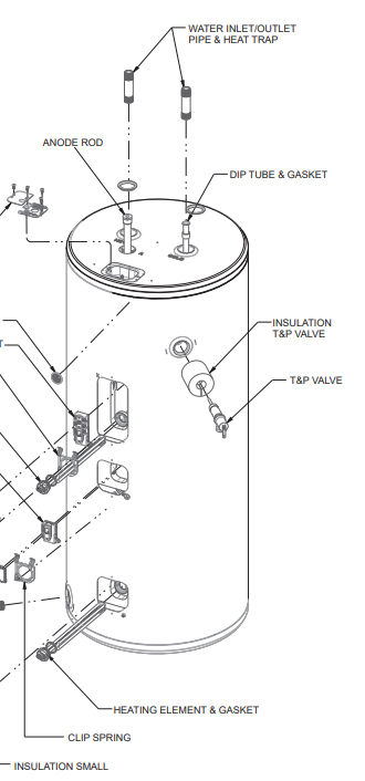
- See page 11 for product schematic.
Anode Rod
- Anode rods are designed and installed to protect and extend the life of residential water storage tanks.
- The anode rod must be removed from the water heater’s tank and inspected annually, and replaced when more than 6” (15.2 cm) of core wire is exposed at either end of the rod.* NOTE: Artificially softened water will cause the anode rod to consume more rapidly.
- Due to shock hazard and to prevent accidental water leaks, this inspection should be done by a qualified servicer or plumber, and requires that the electric power and cold water supply be turned off before servicing the anode rod.
NOTICE:
- Do not remove the anode rod from the water heater’s tank except for inspection and/or replacement, as operation with the anode rod removed will shorten the life of the glass-lined tank and will void warranty coverage.
- Some areas have water conditions that may cause an odor to develop in the water heater. Special alloy replacement rods are available to address the condition.
NOTE:
- Failure to replace the anode rod when consumed voids the warranty for the tank. Warranty coverage for all other components remains intact, and is unaffected by this maintenance requirement.
- The replacement anode rod, and the inspection for consumption are not covered by warranty
INSTALLATION
LOCAL INSTALLATION REGULATIONS
- This water heater must be installed in accordance with these instructions, local codes, utility codes, utility company requirements or, in the absence of local codes, the latest edition of the National Electrical
- Code. It is available from some local libraries or can be purchased from the National Fire Prevention
- Association, Batterymarch park, Quincy, MA 02169 as booklet ANSI/NFPA 70.
POWER REQUIREMENTS
- Check the markings on the rating plate of the water heater to be certain the power supply corresponds to the water heater requirements.
NOTE:
- 208V installations may experience lower performance.
LOCATION
- The water heater and water lines should be protected from freezing temperatures and high-corrosive atmospheres. Do not install the water heater in outdoor, unprotected areas.
- Locate the water heater in a clean dry area as near as practical to the area of greatest heated water demand.
- Long uninsulated hot water lines can waste energy and water. Unit must be installed in a level location.
- If required, add shims under base of unit to level for proper operation.
NOTE: This unit is designed for any common indoor installation.
- Servicing the water heater requires proper installation such that front panels can be removed to permit inspection and servicing. Reference installation instructions found in this manual.
- Moving the water heater or other appliances to provide service to the water heater is not covered under warranty.
Required clearances:
- There must be sufficient clearance between any object and the top, rear and sides of the water heater in the event service is needed.
- The controls and drain at front of unit must have clear access for operation and service. Installations that require minimal clearance on the sides or rear of the water heater for earthquake straps are also acceptable.
- In these cases, additional clearance should be provided on the opposite side of the unit to allow for service access.
CATCH PAN INSTALLATION

NOTE:
- Auxiliary catch pan MUST conform to local codes. Catch Pan Kits are available from the store where the water heater was purchased, a builder store or any water heater distributor.
- The catch pan should be 2” (5.1 cm) minimum larger than the
Water Heater base diameter.
- To prevent corrosion and improve Drain Valve access it is recommended that the water heater be placed on spacers inside the catch pan.
Relief Valve
- Drain Line
- Catch Pan
- Drain (piped to suitable drain)
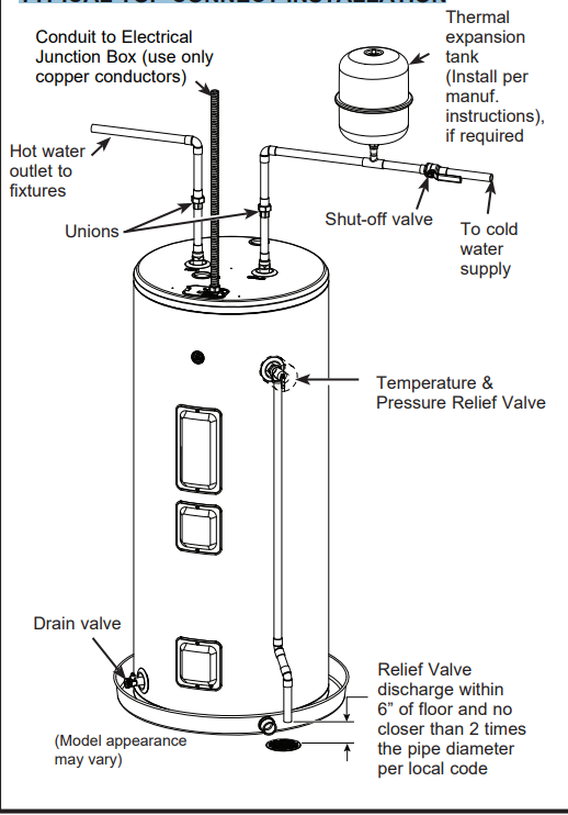
THERMAL EXPANSION
- If a check valve is present on the inlet water line, it will create a “closed system.” Heating water in a closed system creates an increase in pressure within the water system because the pressure is not able to dissipate in the main supply line.
- Referred to as “thermal expansion”, the rapid pressure increase can cause the relief valve to operate (releasing water) during each heating cycle, potentially causing premature failure to the valve or even the water heater.
- The suggested method of controlling thermal expansion is to install an expansion tank in the cold water line between the water heater and the check valve as shown in the following illustrations.
- Contact your installing contractor, water supplier, or plumbing inspector for additional information.
WATER SUPPLY CONNECTIONS
- Refer to the illustration below for recommended installation. The HOT and COLD water connections are clearly marked and are ¾” NPT on all models.
- When connecting to the inlet/outlet ports, the use of ¾” female NPT tapered thread fittings with use of thread sealant is recommended.
- The installation of unions is recommended on the hot and cold water connections so that the water heater may be easily disconnected for servicing if necessary. Piping should be routed to allow anode rod removal.
NOTE:
- Install a shut-off valve in the cold water line near the water heater. This will enable easier service or maintenance of the unit later.
TYPICAL TOP CONNECT INSTALLATION
HOT AND COLD PIPE INSULATION INSTALLATION
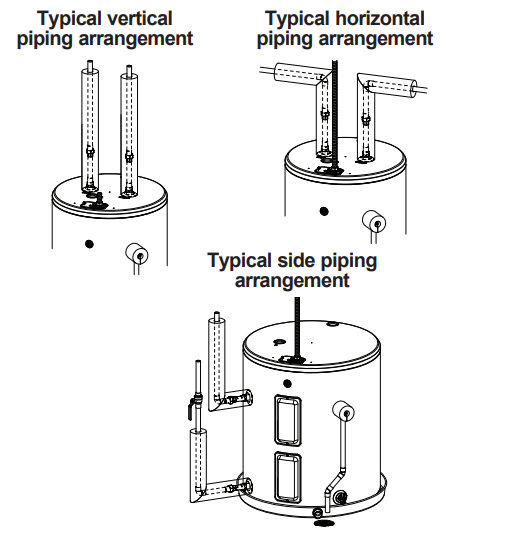
- For increased energy efficiency, some water heaters have been supplied with two 24” sections of pipe insulation.
- Please install the insulation, according to the illustrations above, that best meets your requirements
INSTRUCTIONS
TO FILL THE WATER HEATER
- Make certain the drain valve is completely closed.
- Open the shut-off valve in the cold water supply line.
- Open each hot water faucet slowly to allow the air to vent from the water heater and piping.
- A steady flow of water from the hot water faucet(s) indicates a full water heater.
- Condensation can form on the tank and fittings when it is first filled with water. Condensation may also occur with a heavy water draw and very cold inlet water temperature.
- This condition is not unusual and will disappear once water is heated. If condition persists, examine fittings for potential leaks and repair, as required.
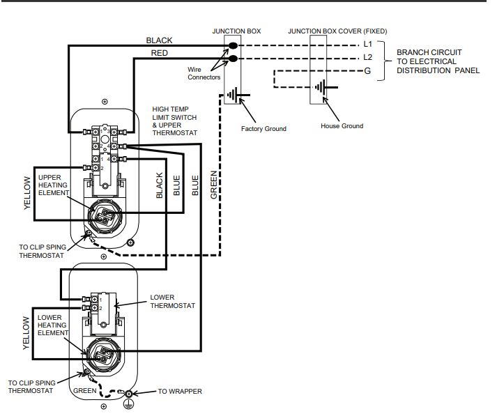
NOTICE
- Do not mis-wire electrical connections. 240VAC or
- VAC must be applied across L1 and L2 wires as shown in ‘Water heater junction box’ illustration.
- If a 4-conductor wire is supplied to the water heater, cap the neutral, and connect the remaining wires as illustrated.
- The branch circuit wiring should include either:
- Metallic conduit or metallic sheathed cable approved for use as a grounding conductor and installed with fittings approved for the purpose.
- Nonmetallic sheathed cable, metallic conduit or metallic sheathed cable not approved for use as a ground conductor shall include a separate conductor for grounding. It should be attached to the ground terminals of the water heater and the electrical distribution box.
To connect power to the water heater:
- Turn the power off.
- Remove the screw/screws holding the junction box top cover.
- Install L1 to L1, L2 to L2 and ground wire onto the fixed junction box cover, per illustration below.
- Reconnect all screws attaching the junction box covers
TROUBLESHOOTING TIPS
Not enough or no hot water
- Water temperature may be set too low
- Cold water inlet temperature may be colder during the winter months
- Leaking or open hot water faucets
- Long runs of exposed pipe, or hot water piping on outside wall
- Dip tube damaged
- A fuse is blown, circuit breaker tripped, or electric service to your home may be interrupted
- Inadequate wiring
- See the Water Temperature Adjustment and Water Heater Capacity sections. (Pages 4 and 6)
- This is normal. The colder inlet water takes longer to heat. • Consider increasing the set temperature as described in the Water Temperature Adjustment section.
- Make sure all faucets are closed.
- Insulate piping.
- Contact your local installer, plumbing contractor, or previously agreed upon service agency.
- Replace fuse or reset circuit breaker.
- Contact the local electric utility
- See the Installation Instructions
- See the Safety Controls section, see page 5.
- Correct piping connections
Water is too hot
- Water temperature is set too high
- Thermostat has failed
• See the Water Temperature Adjustment section.
• Contact your local installer, plumbing contractor, or previously agreed upon service agency
Hot water has a rotten
- Certain water supplies with high sulfate content will react with the anode rod that is present in all water heaters for corrosion protection of the tan
- The odor can be reduced or eliminated in most water heaters by replacing the anode rod with less-active material rod. In some cases, an added step of chlorinating the water heater and all hot water lines may be necessary, contact your local water professional or plumber for options and instructions.
- Go to GEAppliances.com/waterheater for information on purchasing this replacement anode rod. A qualified servicer or plumber should do this replacement. Use of a non-GE Appliances approved anode rod, or operating the water heater without a GE Appliances approved anode rod will VOID the warranty.
- In certain cases, increasing the tank temperature to 140°F (60°C) can reduce this odor issue. Reference the Water Temperature Adjustment section of the Important Safety Information of this manual for procedure and dangers of scalding water. Installation of temperature limiting valves can be used to reduce risk of scalding.
REPLACEMENT PARTS
All parts orders should include:
1. The model and serial number of the water heater from the rating plate.
2. Specify voltage and wattage as marked on the rating plate.
3. Part description (as noted below) and number of parts desired.
CAUTION
- For your safety, DO NOT attempt repair of electrical wiring, thermostat(s), heating elements or other operating controls. Refer repairs to qualified service personnel.
WIRING DIAGRAM
LIMITED WARRANTY
- This limited warranty is extended to the original purchaser and any succeeding owner for products purchased for home use within the USA.
- If the product is located in an area where service by a GE Appliances Authorized Servicer is not available, you may be responsible for a trip charge or you may be required to bring the product to an Authorized GE Appliances Service location for service.
- In Alaska, the limited warranty excludes the cost of shipping or service calls to your home. Some states do not allow the exclusion or limitation of incidental or consequential damages. This limited warranty gives you specific legal rights, and you may also have other rights which vary from state to state. To know what your legal rights are, consult your local or state consumer affairs office or your state’s Attorney General.
CONSUMER SUPPORT
- Consumer Service If you have a question or need assistance with your new water heater on adjustments, repairs, or routine maintenance:
- Review the Troubleshooting Tips or Care and Cleaning sections of this Owner’s Manual.
- Contact your local installer, plumbing contractor, or call GE Appliances Service and Support at 1-800-943-8186.
NOTE:
- Your installer phone number may be located on the product label. If you still have issues, contact the GEA Customer Support at GEAppliances.com/waterheater