USER GUIDE & SERVICE MANUAL
SAFETY • INSTALLATION & INTEGRATION • OPERATING INSTRUCTIONS • MAINTENANCE • SERVICE
Modular 3000 Series •
3036BVWC •
36" Beverage Center
RIGHT PRODUCT. RIGHT PLACE. RIGHT TEMPERATURE. SINCE 1962.
USER GUIDE & SERVICE MANUAL
u-line.com
Table of Contents
Intro
Safety
Safety and Warning
Disposal And Recycling
Installation
Environmental Requirements
Electrical
Cutout Dimensions
Product Dimensions
Side by Side Installation
Anti-Tip Bracket
General Installation
Integrated Grille Dimensions
Grille / Plinth Installation
Door Swing
Door Stop
Door Adjust
Maintenance
Cleaning
Cleaning Condenser
Extended Non-Use
Operating Instructions
First Use
Sabbath Mode
Airflow and Product Loading
U-Line Wine Guide
Recommended Wine Storage
Service
Interior Shelves
Wine Rack Installation
Troubleshooting
Wire Diagram
Product Liability
Warranty Claims
Parts
Ordering Replacement Parts
R600a Specifications
System Diagnosis Guide
Compressor Specifications
Troubleshooting Extended
Control Operation - Service
Thermistor
Defrost
Remove Fan and Cover
Warranty
USER GUIDE
u-line.com
Introduction
WELCOME TO U-LINE
Congratulations on your U-Line purchase. Your product comes from a company with over ve decades of premium modular ice
making, refrigeration, and wine preservation experience. U-Line creates products focused on functionality, style, and inspired
innovations — paying close attention to even the smallest details. Applications include residential, outdoor, ADA height
compliant, marine, and commercial. Complete product categories include Beverage Centers, Wine Refrigerators, Ice Machines,
Refrigerators, Freezers, and Dispensers.
Our advanced refrigeration systems, large and exible capacities, and Built-In to Stand Out
®
clean integrated look allow you
to preserve the right product, in the right place, at the right temperature. Since 2014, U-Line has been part of the Middleby
family of brands. All products are designed, engineered, and assembled in Milwaukee, Wisconsin, USA, and select products
are available worldwide.
PRODUCT INFORMATION
Looking for additional information on your product? User Guides, Spec Sheets, CAD Drawings, Compliance Documentation,
and Product Warranty information are all available for reference and download at u-line.com.
PROPERTY DAMAGE / INJURY CONCERNS
In the unlikely event property damage or personal injury is suspected related to a U-Line product, please take the following
steps:
1. U-Line Customer Care must be contacted immediately at +1.414.354.0300.
2. Service or repairs performed on the unit without prior written approval from U-Line is not permitted. If the unit has been
altered or repaired in the eld without prior written approval from U-Line, claims will not be eligible.
GENERAL INQUIRIES
U-Line Corporation
8900 N. 55th Street
Milwaukee, Wisconsin 53223 USA
Monday - Friday 8:00 am to 4:30 pm CST
T: +1.414.354.0300
Email: sales@u-line.com
u-line.com
CONNECT WITH US
SERVICE & PARTS ASSISTANCE
Monday - Friday 8:00 am to 4:30 pm CST
T: +1.800.779.2547
Service Email: onlineservice@u-line.com
Parts Email: onlineparts@u-line.com
Designed, engineered and assembled in WI, USA
3
USER GUIDE
Safety and Warning 1
u-line.com
SAFETY • INSTALLATION & INTEGRATION • OPERATING INSTRUCTIONS • MAINTENANCE • SERVICE
Safety and Warning
NOTICE
Please read all instructions before installing,
operating, or servicing the appliance.
Use this appliance for its intended purpose only and follow
these general precautions with those listed throughout this
guide:
SAFETY ALERT DEFINITIONS
Throughout this guide are safety items labeled with a
Danger, Warning or Caution based on the risk type:
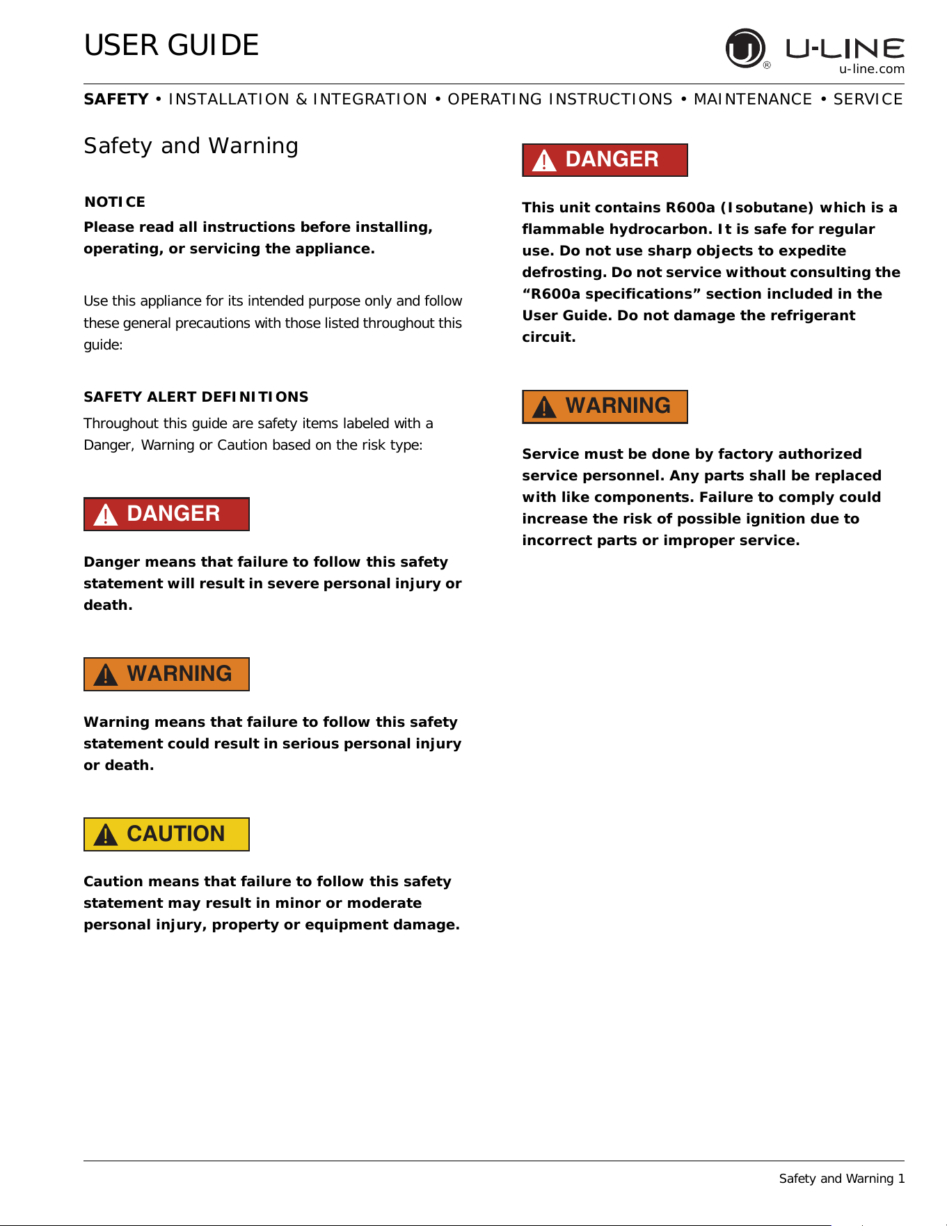
DANGER
!
Danger means that failure to follow this safety
statement will result in severe personal injury or
death.
WARNING
!
Warning means that failure to follow this safety
statement could result in serious personal injury
or death.
CAUTION
!
Caution means that failure to follow this safety
statement may result in minor or moderate
personal injury, property or equipment damage.
DANGER
!
This unit contains R600a (Isobutane) which is a
flammable hydrocarbon. It is safe for regular
use. Do not use sharp objects to expedite
defrosting. Do not service without consulting the
“R600a specifications” section included in the
User Guide. Do not damage the refrigerant
circuit.
WARNING
!
Service must be done by factory authorized
service personnel. Any parts shall be replaced
with like components. Failure to comply could
increase the risk of possible ignition due to
incorrect parts or improper service.
4
USER GUIDE
Disposal and Recycling 1
u-line.com
SAFETY • INSTALLATION & INTEGRATION • OPERATING INSTRUCTIONS • MAINTENANCE • SERVICE
Disposal and Recycling
DANGER
!
RISK OF CHILD ENTRAPMENT. Before you throw
away your old refrigerator or freezer, take off
the doors and leave shelves in place so children
may not easily climb inside.
If the unit is being removed from service for disposal,
check and obey all federal, state and local regulations
regarding the disposal and recycling of refrigeration
appliances, and follow these steps completely:
1. Remove all consumable contents from the unit.
2. Unplug the electrical cord from its socket.
3. Remove the door(s)/drawer(s).
5
USER GUIDE
Environmental Requirements 1
u-line.com
SAFETY • INSTALLATION & INTEGRATION • OPERATING INSTRUCTIONS • MAINTENANCE • SERVICE
Environmental Requirements
This model is intended for indoor/interior applications only
and is not to be used in installations that are open/
exposed to natural elements.
This unit is designed to operate between 50°F (10°C) and
100°F (38°C). Higher ambient temperatures may reduce
the unit’s ability to reach low temperatures and/or reduce
ice production on applicable models.
For best performance, keep the unit out of direct sunlight
and away from heat generating equipment.
In climates where high humidity and dew points are
present, condensation may appear on outside surfaces.
This is considered normal. The condensation will
evaporate when the humidity drops.
CAUTION
!
Damages caused by ambient temperatures of
40°F (4°C) or below are not covered by the
warranty.
6
USER GUIDE
Electrical
u-line.com
Electrical
WARNING
!
SHOCK HAZARD — Electrical Grounding
Required. Never attempt to repair or perform
maintenance on the unit until the electricity has
been disconnected.
Never remove the round grounding prong from
the plug and never use a two-prong grounding
adapter.
Altering, cutting or removing power cord,
removing power plug, or direct wiring can cause
serious injury, fire, loss of property and/or life,
and will void the warranty.
Never use an extension cord to connect power to
the unit.
Always keep your working area dry.
NOTICE
Electrical installation must observe all state and
local codes. This unit requires connection to a
grounded (three-prong), polarized receptacle
that has been placed by a qualified electrician.
The unit requires a grounded and polarized 115 VAC,
60 Hz, 15A power supply (normal household current). An
individual, properly grounded branch circuit or circuit
breaker is recommended. A GFCI (ground fault circuit
interrupter) is usually not required for fixed location
appliances and is not recommended for your unit because
it could be prone to nuisance tripping. However, be sure
to consult your local codes.
See CUTOUT DIMENSIONS for recommended receptacle
location.
7
USER GUIDE
Cutout Dimensions 1
u-line.com
SAFETY • INSTALLATION & INTEGRATION • OPERATING INSTRUCTIONS • MAINTENANCE • SERVICE
Cutout Dimensions
PREPARE SITE
Your U-Line product has been designed exclusively for a
built-in installation. When built-in, your unit does not
require additional air space for top, sides, or rear.
However, the front grille must NOT be obstructed.
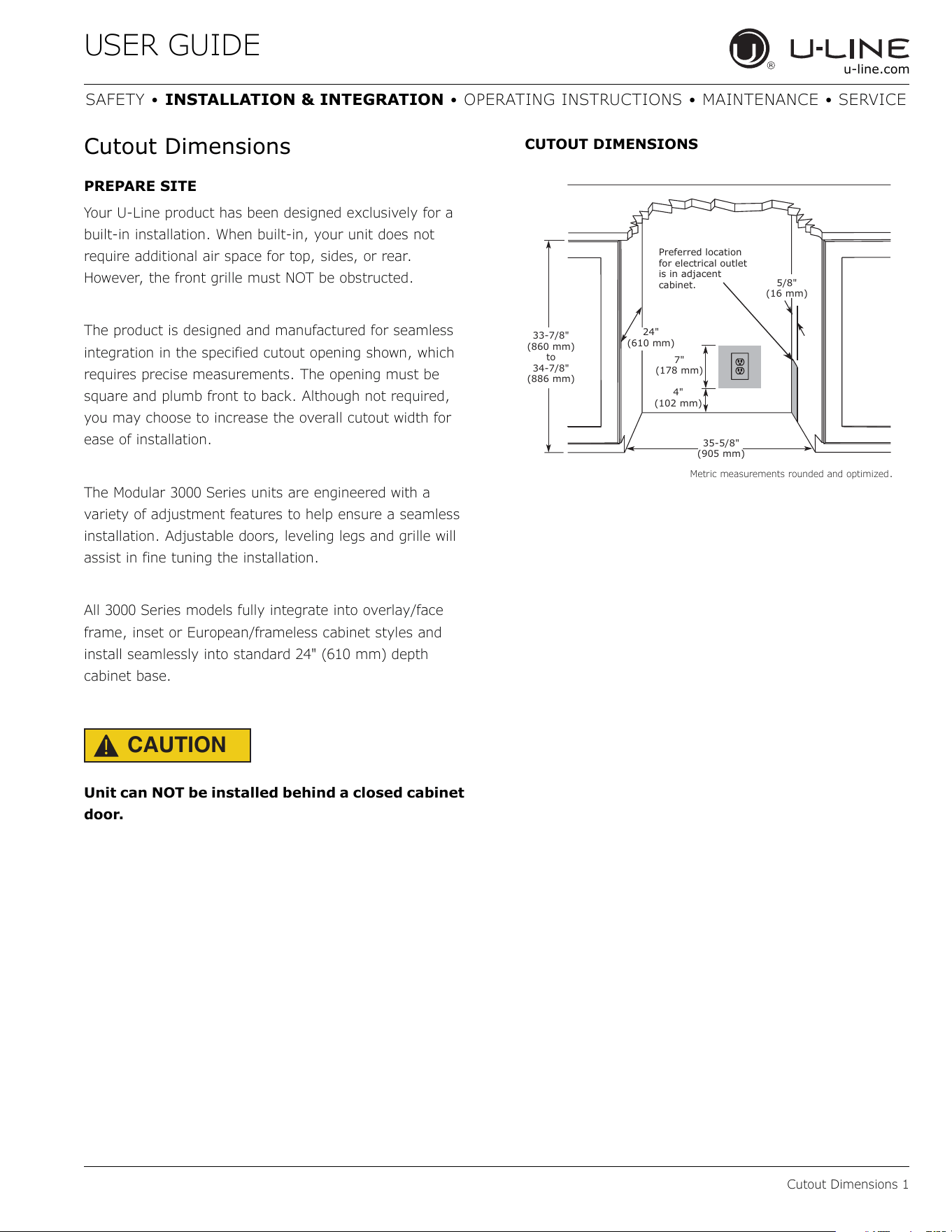
The product is designed and manufactured for seamless
integration in the specified cutout opening shown, which
requires precise measurements. The opening must be
square and plumb front to back. Although not required,
you may choose to increase the overall cutout width for
ease of installation.
The Modular 3000 Series units are engineered with a
variety of adjustment features to help ensure a seamless
installation. Adjustable doors, leveling legs and grille will
assist in fine tuning the installation.
All 3000 Series models fully integrate into overlay/face
frame, inset or European/frameless cabinet styles and
install seamlessly into standard 24" (610 mm) depth
cabinet base.
CAUTION
!
Unit can NOT be installed behind a closed cabinet
door.
CUTOUT DIMENSIONS
Metric measurements rounded and optimized.
4"
(102 mm)
7"
(178 mm)
35-5/8"
(905 mm)
33-7/8"
(860 mm)
to
34-7/8"
(886 mm)
Preferred location
for electrical outlet
is in adjacent
cabinet.
5/8"
(16 mm)
24"
(610 mm)
8
USER GUIDE
Product Dimensions 1
u-line.com
SAFETY • INSTALLATION & INTEGRATION • OPERATING INSTRUCTIONS • MAINTENANCE • SERVICE
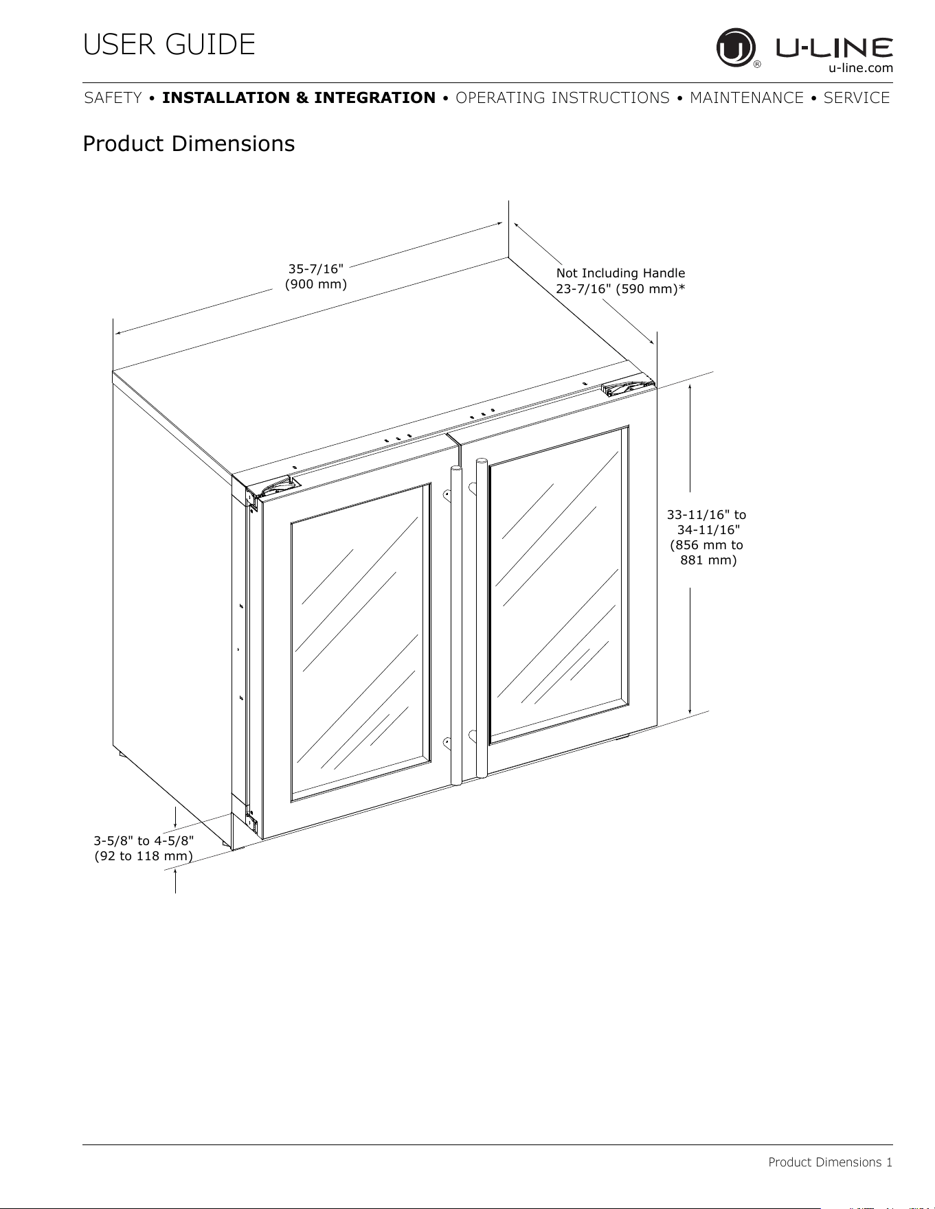
Product Dimensions
35-7/16"
(900 mm)
33-11/16" to
34-11/16"
(856 mm to
881 mm)
Not Including Handle
23-7/16" (590 mm)*
3-5/8" to 4-5/8"
(92 to 118 mm)
9
USER GUIDE
Side-by-Side Installation 1
u-line.com
SAFETY • INSTALLATION & INTEGRATION • OPERATING INSTRUCTIONS • MAINTENANCE • SERVICE
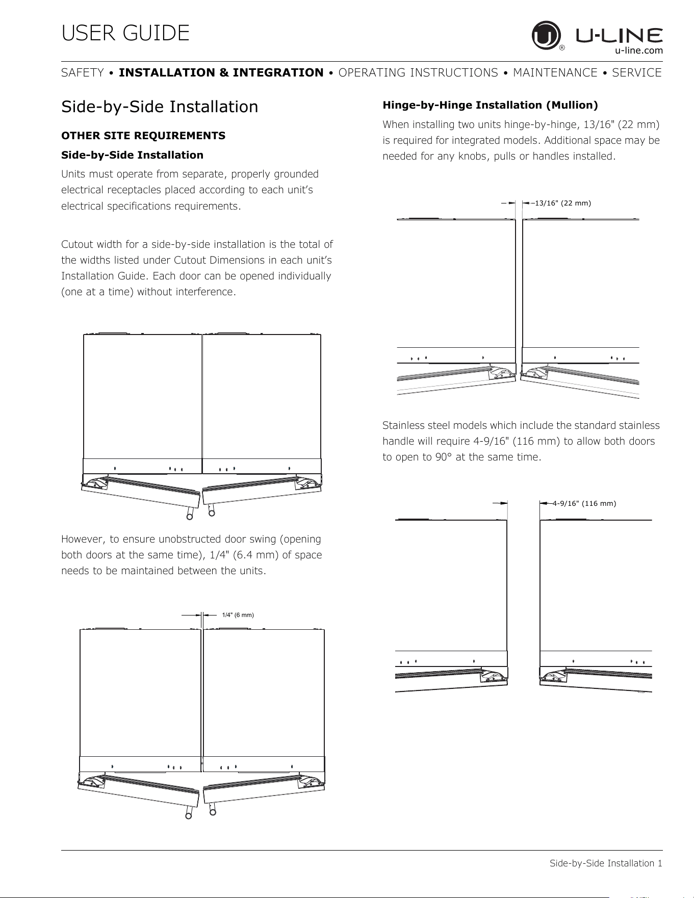
Side-by-Side Installation
OTHER SITE REQUIREMENTS
Side-by-Side Installation
Units must operate from separate, properly grounded
electrical receptacles placed according to each unit’s
electrical specifications requirements.
Cutout width for a side-by-side installation is the total of
the widths listed under Cutout Dimensions in each unit’s
Installation Guide. Each door can be opened individually
(one at a time) without interference.
However, to ensure unobstructed door swing (opening
both doors at the same time), 1/4" (6.4 mm) of space
needs to be maintained between the units.
Hinge-by-Hinge Installation (Mullion)
When installing two units hinge-by-hinge, 13/16" (22 mm)
is required for integrated models. Additional space may be
needed for any knobs, pulls or handles installed.
Stainless steel models which include the standard stainless
handle will require 4-9/16" (116 mm) to allow both doors
to open to 90° at the same time.
1/4" (6 mm)
13/16" (22 mm)
4-9/16" (116 mm)
10
USER GUIDE
Anti-Tip Bracket 1
u-line.com
SAFETY • INSTALLATION & INTEGRATION • OPERATING INSTRUCTIONS • MAINTENANCE • SERVICE
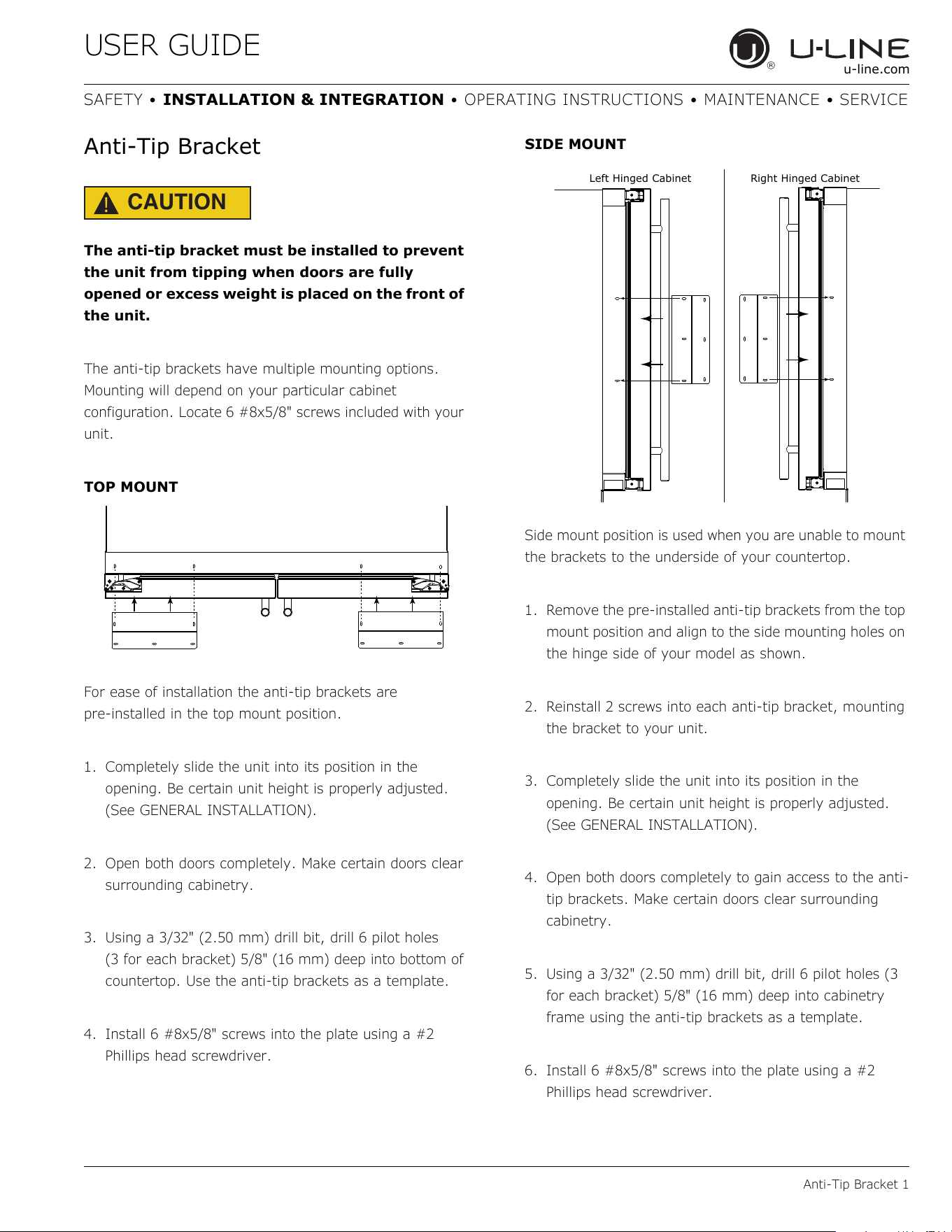
Anti-Tip Bracket
CAUTION
!
The anti-tip bracket must be installed to prevent
the unit from tipping when doors are fully
opened or excess weight is placed on the front of
the unit.
The anti-tip brackets have multiple mounting options.
Mounting will depend on your particular cabinet
configuration. Locate 6 #8x5/8" screws included with your
unit.
TOP MOUNT
For ease of installation the anti-tip brackets are
pre-installed in the top mount position.
1. Completely slide the unit into its position in the
opening. Be certain unit height is properly adjusted.
(See GENERAL INSTALLATION).
2. Open both doors completely. Make certain doors clear
surrounding cabinetry.
3. Using a 3/32" (2.50 mm) drill bit, drill 6 pilot holes
(3 for each bracket) 5/8" (16 mm) deep into bottom of
countertop. Use the anti-tip brackets as a template.
4. Install 6 #8x5/8" screws into the plate using a #2
Phillips head screwdriver.
SIDE MOUNT
Side mount position is used when you are unable to mount
the brackets to the underside of your countertop.
1. Remove the pre-installed anti-tip brackets from the top
mount position and align to the side mounting holes on
the hinge side of your model as shown.
2. Reinstall 2 screws into each anti-tip bracket, mounting
the bracket to your unit.
3. Completely slide the unit into its position in the
opening. Be certain unit height is properly adjusted.
(See GENERAL INSTALLATION).
4. Open both doors completely to gain access to the anti-
tip brackets. Make certain doors clear surrounding
cabinetry.
5. Using a 3/32" (2.50 mm) drill bit, drill 6 pilot holes (3
for each bracket) 5/8" (16 mm) deep into cabinetry
frame using the anti-tip brackets as a template.
6. Install 6 #8x5/8" screws into the plate using a #2
Phillips head screwdriver.
Left Hinged Cabinet
Right Hinged Cabinet
11
USER GUIDE
General Installation 1
u-line.com
SAFETY • INSTALLATION & INTEGRATION • OPERATING INSTRUCTIONS • MAINTENANCE • SERVICE
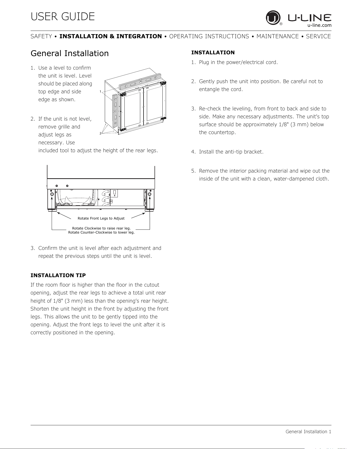
General Installation
1. Use a level to confirm
the unit is level. Level
should be placed along
top edge and side
edge as shown.
2. If the unit is not level,
remove grille and
adjust legs as
necessary. Use
included tool to adjust the height of the rear legs.
3. Confirm the unit is level after each adjustment and
repeat the previous steps until the unit is level.
INSTALLATION TIP
If the room floor is higher than the floor in the cutout
opening, adjust the rear legs to achieve a total unit rear
height of 1/8" (3 mm) less than the opening’s rear height.
Shorten the unit height in the front by adjusting the front
legs. This allows the unit to be gently tipped into the
opening. Adjust the front legs to level the unit after it is
correctly positioned in the opening.
INSTALLATION
1. Plug in the power/electrical cord.
2. Gently push the unit into position. Be careful not to
entangle the cord.
3. Re-check the leveling, from front to back and side to
side. Make any necessary adjustments. The unit’s top
surface should be approximately 1/8" (3 mm) below
the countertop.
4. Install the anti-tip bracket.
5. Remove the interior packing material and wipe out the
inside of the unit with a clean, water-dampened cloth.
1
2
Rotate Clockwise to raise rear leg.
Rotate Counter-Clockwise to lower leg.
Rotate Front Legs to Adjust
12
USER GUIDE
Integrated Grille - Plinth Dimensions 1
u-line.com
SAFETY • INSTALLATION & INTEGRATION • OPERATING INSTRUCTIONS • MAINTENANCE • SERVICE
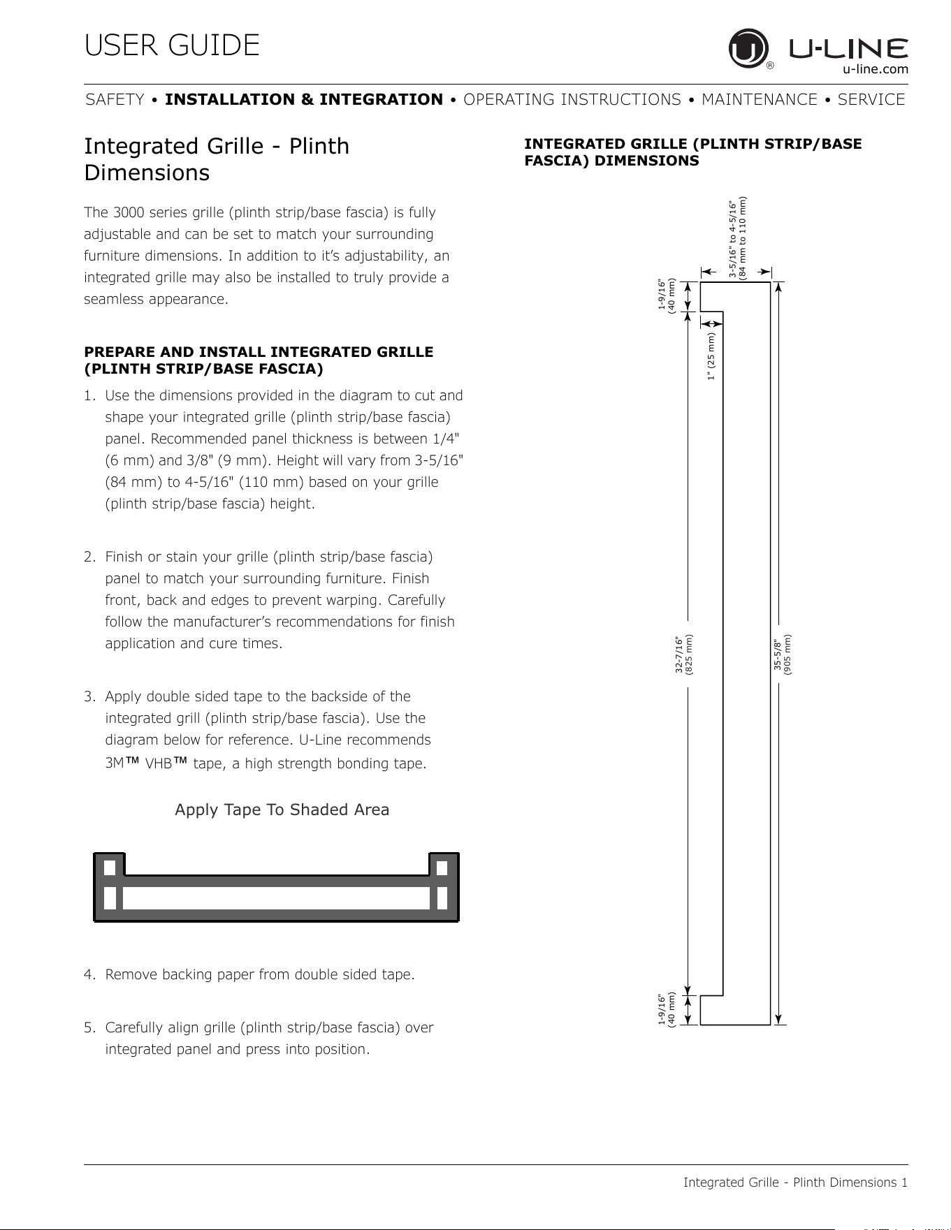
Integrated Grille - Plinth
Dimensions
The 3000 series grille (plinth strip/base fascia) is fully
adjustable and can be set to match your surrounding
furniture dimensions. In addition to it’s adjustability, an
integrated grille may also be installed to truly provide a
seamless appearance.
PREPARE AND INSTALL INTEGRATED GRILLE
(PLINTH STRIP/BASE FASCIA)
1. Use the dimensions provided in the diagram to cut and
shape your integrated grille (plinth strip/base fascia)
panel. Recommended panel thickness is between 1/4"
(6 mm) and 3/8" (9 mm). Height will vary from 3-5/16"
(84 mm) to 4-5/16" (110 mm) based on your grille
(plinth strip/base fascia) height.
2. Finish or stain your grille (plinth strip/base fascia)
panel to match your surrounding furniture. Finish
front, back and edges to prevent warping. Carefully
follow the manufacturer’s recommendations for finish
application and cure times.
3. Apply double sided tape to the backside of the
integrated grill (plinth strip/base fascia). Use the
diagram below for reference. U-Line recommends
3M
™ VHB™ tape, a high strength bonding tape.
4. Remove backing paper from double sided tape.
5. Carefully align grille (plinth strip/base fascia) over
integrated panel and press into position.
INTEGRATED GRILLE (PLINTH STRIP/BASE
FASCIA) DIMENSIONS
Apply Tape To Shaded Area
32-7/16"
(825 mm)
35-5/8"
(905 mm)
1-9/16
"
(40 mm)
1-9/16"
(40 mm)
1" (25 mm)
3-5/16" to 4-5/16"
(84 mm to 110 mm)
13
USER GUIDE
Grille - Plinth Installation 1
u-line.com
SAFETY • INSTALLATION & INTEGRATION • OPERATING INSTRUCTIONS • MAINTENANCE • SERVICE
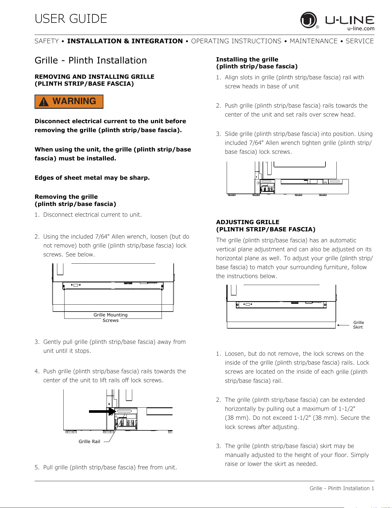
Grille - Plinth Installation
REMOVING AND INSTALLING GRILLE
(PLINTH STRIP/BASE FASCIA)
WARNING
!
Disconnect electrical current to the unit before
removing the grille (plinth strip/base fascia).
When using the unit, the grille (plinth strip/base
fascia) must be installed.
Edges of sheet metal may be sharp.
Removing the grille
(plinth strip/base fascia)
1. Disconnect electrical current to unit.
2. Using the included 7/64" Allen wrench, loosen (but do
not remove) both grille (plinth strip/base fascia) lock
screws. See below.
3. Gently pull grille (plinth strip/base fascia) away from
unit until it stops.
4. Push grille (plinth strip/base fascia) rails towards the
center of the unit to lift rails off lock screws.
5. Pull grille (plinth strip/base fascia) free from unit.
Installing the grille
(plinth strip/base fascia)
1. Align slots in
grille (plinth strip/base fascia)
rail with
screw heads in base of unit
2. Push grille (plinth strip/base fascia) rails towards the
center of the unit and set rails over screw head.
3. Slide grille (plinth strip/base fascia) into position. Using
included 7/64" Allen wrench tighten grille (plinth strip/
base fascia) lock screws.
ADJUSTING GRILLE
(PLINTH STRIP/BASE FASCIA)
The
grille (plinth strip/base fascia
) has an automatic
vertical plane adjustment and can also be adjusted on its
horizontal plane as well. To adjust your
grille (plinth strip/
base fascia
) to match your surrounding furniture, follow
the instructions below.
1. Loosen, but do not remove, the lock screws on the
inside of the
grille (plinth strip/base fascia)
rails. Lock
screws are located on the inside of each
grille (plinth
strip/base fascia)
rail.
2. The grille (plinth strip/base fascia) can be extended
horizontally by pulling out a maximum of 1-1/2"
(38 mm). Do not exceed 1-1/2" (38 mm). Secure the
lock screws after adjusting.
3. The grille (plinth strip/base fascia) skirt may be
manually adjusted to the height of your floor. Simply
raise or lower the skirt as needed.
Grille Mounting
Screws
Grille Rail
Grille
Skirt
14
USER GUIDE
Door Swing 1
u-line.com
SAFETY • INSTALLATION & INTEGRATION • OPERATING INSTRUCTIONS • MAINTENANCE • SERVICE
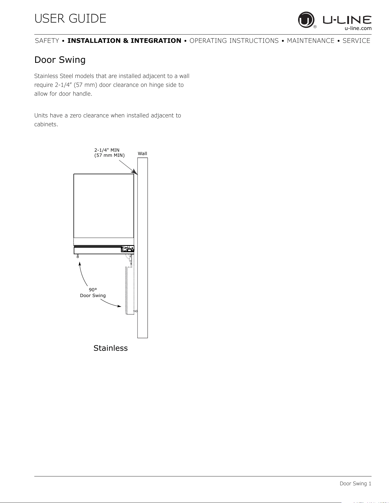
Door Swing
Stainless Steel models that are installed adjacent to a wall
require 2-1/4” (57 mm) door clearance on hinge side to
allow for door handle.
Units have a zero clearance when installed adjacent to
cabinets.
Wall
90°
Door Swing
2-1/4" MIN
(57 mm MIN)
Stainless
15
USER GUIDE
Door Stop 1
u-line.com
SAFETY • INSTALLATION & INTEGRATION • OPERATING INSTRUCTIONS • MAINTENANCE • SERVICE
Door Stop
Your U-Line unit was shipped to you with the optional 90°
pin.
Your unit’s door(s) will open 115° straight from the
factory. If you would like the door stop at 90° follow these
instructions.
NOTICE
If your unit is already undercounter, it will need
to be moved out to access the hinge. With the
90° stop pin in place, you will not be able to
replace the hinge cover.
1. Open door approximately 90°.
2. Remove hinge cover by lifting top and bottom of hinge
cover and sliding the cover inwards to remove from
hinge.
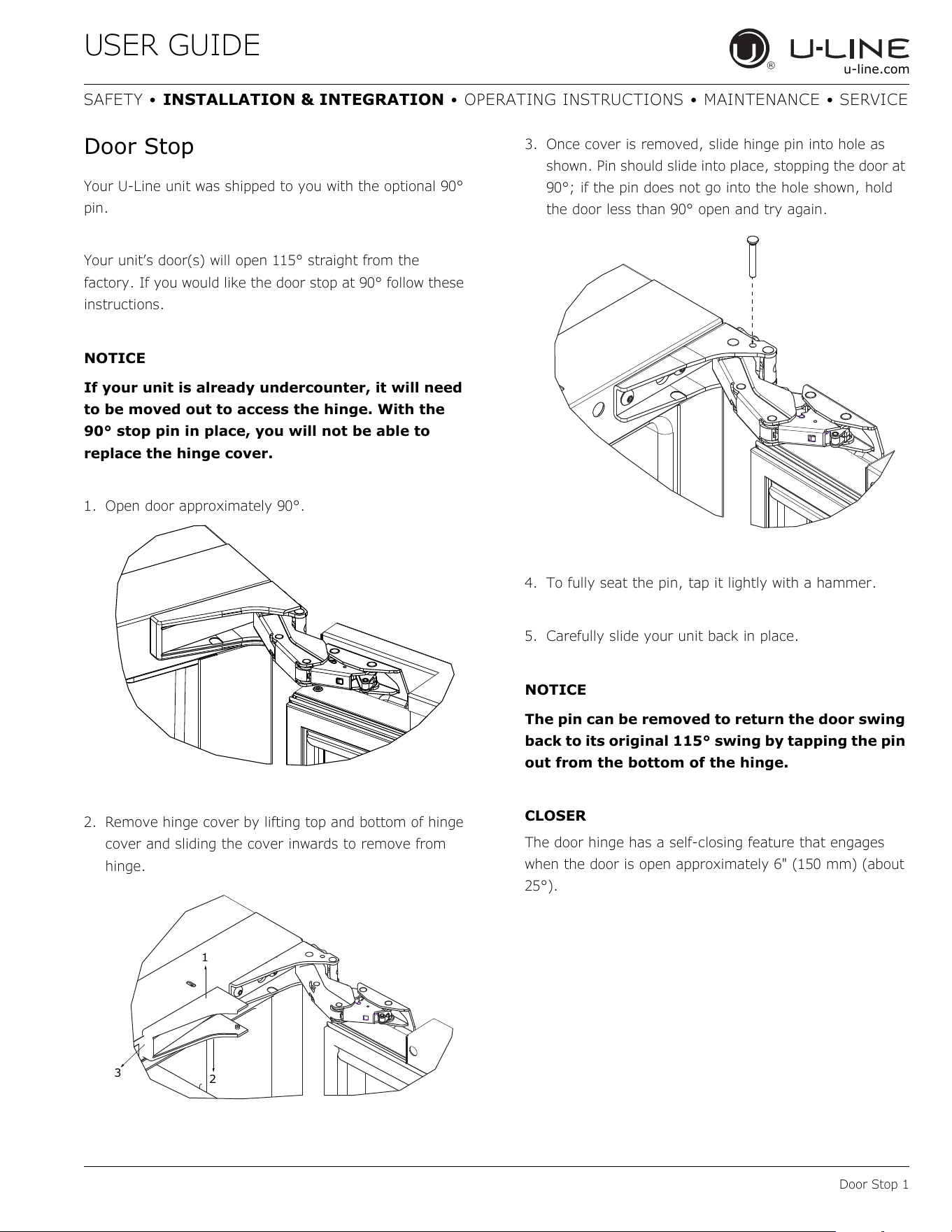
3. Once cover is removed, slide hinge pin into hole as
shown. Pin should slide into place, stopping the door at
90°; if the pin does not go into the hole shown, hold
the door less than 90° open and try again.
4. To fully seat the pin, tap it lightly with a hammer.
5. Carefully slide your unit back in place.
NOTICE
The pin can be removed to return the door swing
back to its original 115° swing by tapping the pin
out from the bottom of the hinge.
CLOSER
The door hinge has a self-closing feature that engages
when the door is open approximately 6" (150 mm) (about
25°).
1
3
2
16
USER GUIDE
Door Adjustments 1
u-line.com
SAFETY • INSTALLATION & INTEGRATION • OPERATING INSTRUCTIONS • MAINTENANCE • SERVICE
Door Adjustments
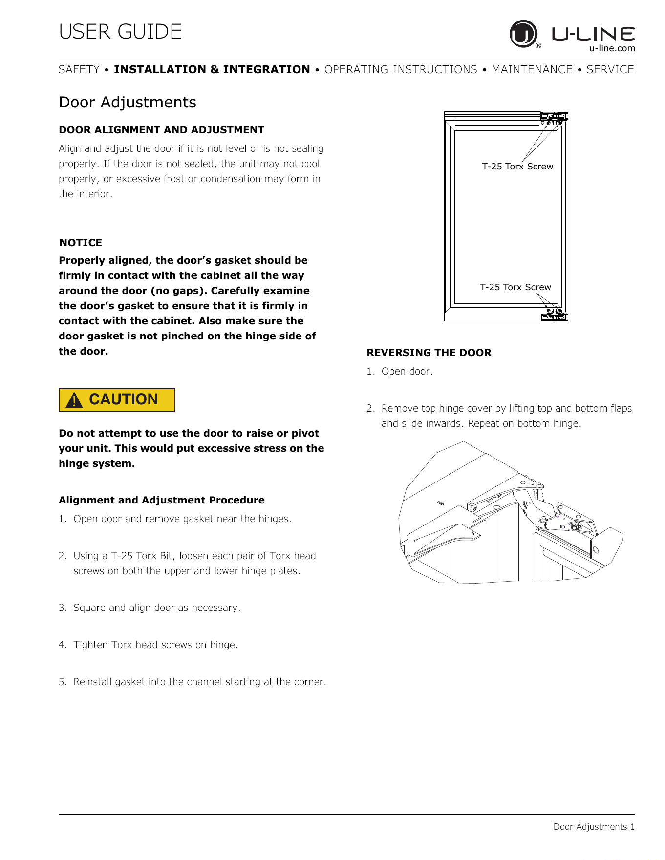
DOOR ALIGNMENT AND ADJUSTMENT
Align and adjust the door if it is not level or is not sealing
properly. If the door is not sealed, the unit may not cool
properly, or excessive frost or condensation may form in
the interior.
NOTICE
Properly aligned, the door’s gasket should be
firmly in contact with the cabinet all the way
around the door (no gaps). Carefully examine
the door’s gasket to ensure that it is firmly in
contact with the cabinet. Also make sure the
door gasket is not pinched on the hinge side of
the door.
CAUTION
!
Do not attempt to use the door to raise or pivot
your unit. This would put excessive stress on the
hinge system.
Alignment and Adjustment Procedure
1. Open door and remove gasket near the hinges.
2. Using a T-25 Torx Bit, loosen each pair of Torx head
screws on both the upper and lower hinge plates.
3. Square and align door as necessary.
4. Tighten Torx head screws on hinge.
5. Reinstall gasket into the channel starting at the corner.
REVERSING THE DOOR
1. Open door.
2. Remove top hinge cover by lifting top and bottom flaps
and slide inwards. Repeat on bottom hinge.
T-25 Torx Screw
T-25 Torx Screw
17
Door Adjustments 2
USER GUIDE
SAFETY • INSTALLATION & INTEGRATION • OPERATING INSTRUCTIONS • MAINTENANCE • SERVICE
u-line.com
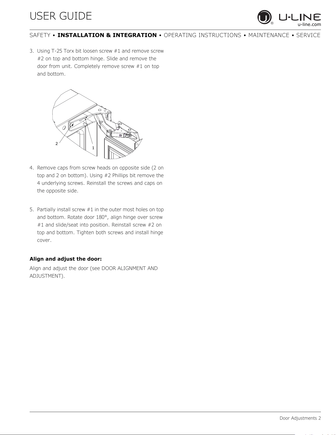
3. Using T-25 Torx bit loosen screw #1 and remove screw
#2 on top and bottom hinge. Slide and remove the
door from unit. Completely remove screw #1 on top
and bottom.
4. Remove caps from screw heads on opposite side (2 on
top and 2 on bottom). Using #2 Phillips bit remove the
4 underlying screws. Reinstall the screws and caps on
the opposite side.
5. Partially install screw #1 in the outer most holes on top
and bottom. Rotate door 180°, align hinge over screw
#1 and slide/seat into position. Reinstall screw #2 on
top and bottom. Tighten both screws and install hinge
cover.
Align and adjust the door:
Align and adjust the door (see DOOR ALIGNMENT AND
ADJUSTMENT).
2
1
18
USER GUIDE
First Use 1
u-line.com
SAFETY • INSTALLATION & INTEGRATION • OPERATING INSTRUCTIONS • MAINTENANCE • SERVICE
First Use
All U-Line controls are preset at the factory. Initial startup
requires no adjustments.
NOTICE
U-Line recommends allowing the unit to run
overnight before loading with product.
When plugged in, the unit will begin operating under the
factory default setting. Follow the on screen prompt for
language selection and temperature units.
To turn the unit off, press and hold for 5 seconds and
release. The display will show a countdown to switching the
unit off.
To power your unit on, simply press and the unit will
immediately switch on.
19
USER GUIDE
Sabbath Mode 1
u-line.com
SAFETY • INSTALLATION & INTEGRATION • OPERATING INSTRUCTIONS • MAINTENANCE • SERVICE
L
Sabbath Mode
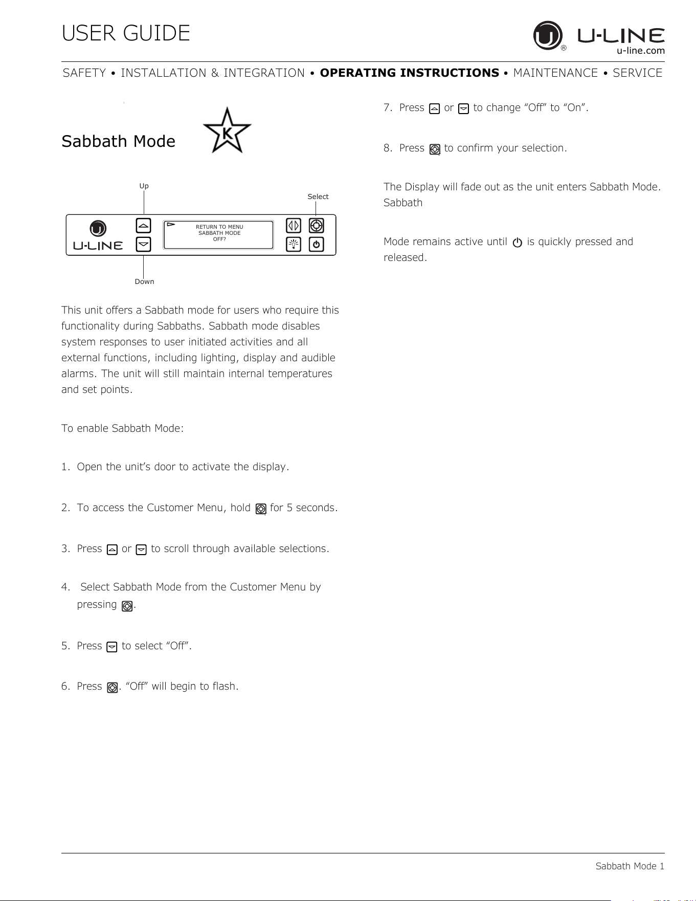
This unit offers a Sabbath mode for users who require this
functionality during Sabbaths. Sabbath mode disables
system responses to user initiated activities and all
external functions, including lighting, display and audible
alarms. The unit will still maintain internal temperatures
and set points.
To enable Sabbath Mode:
1. Open the unit’s door to activate the display.
2. To access the Customer Menu, hold for 5 seconds.
3. Press or to scroll through available selections.
4. Select Sabbath Mode from the Customer Menu by
pressing .
5. Press to select “Off”.
6. Press . “Off” will begin to flash.
7. Press or to change “Off” to “On”.
8. Press to confirm your selection.
The Display will fade out as the unit enters Sabbath Mode.
Sabbath
Mode remains active until is quickly pressed and
released.
Up
Select
Down
RETURN TO MENU
SABBATH MODE
OFF?
20
USER GUIDE
Airflow and Product Loading 1
u-line.com
SAFETY • INSTALLATION & INTEGRATION • OPERATING INSTRUCTIONS • MAINTENANCE • SERVICE
Airflow and Product Loading
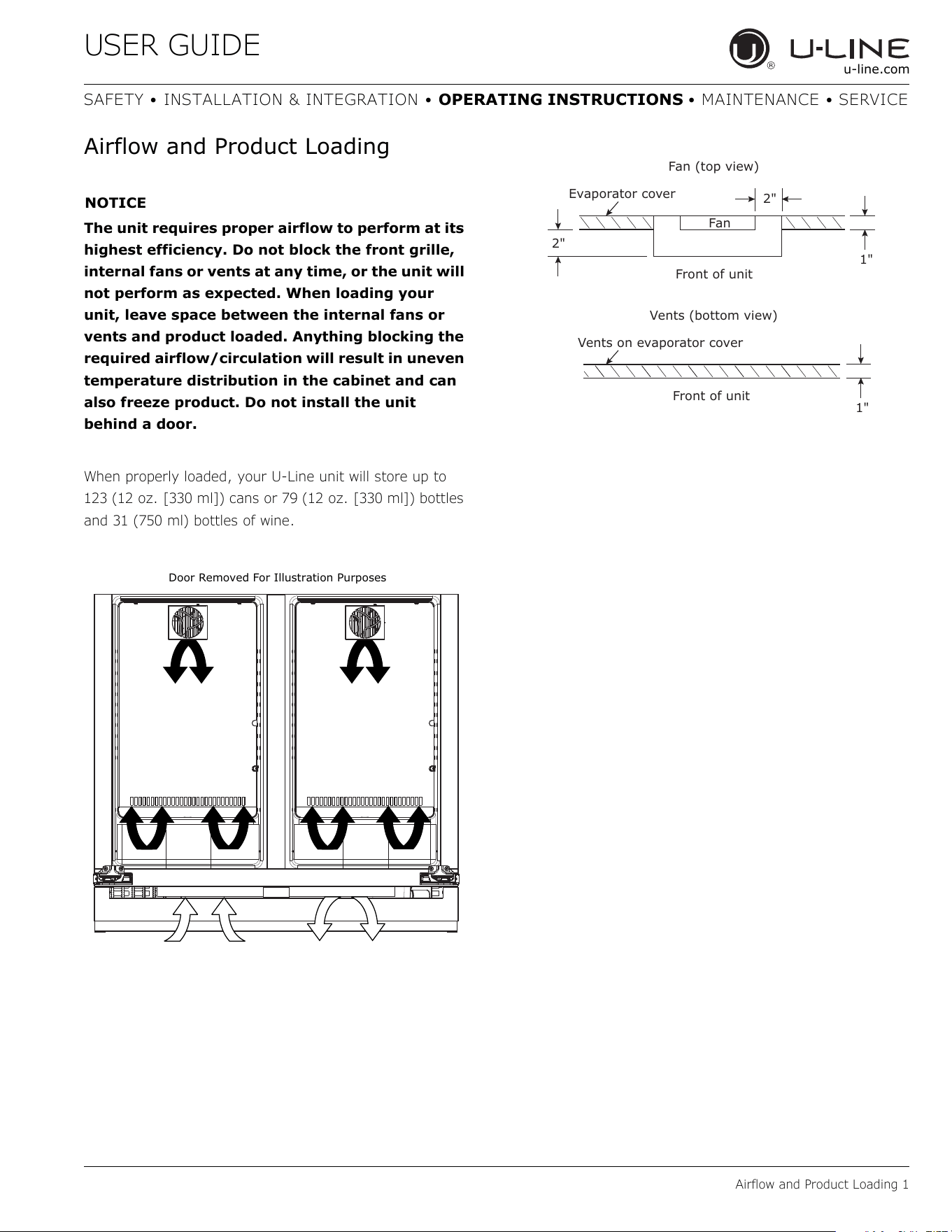
NOTICE
The unit requires proper airflow to perform at its
highest efficiency. Do not block the front grille,
internal fans or vents at any time, or the unit will
not perform as expected. When loading your
unit, leave space between the internal fans or
vents and product loaded. Anything blocking the
required airflow/circulation will result in uneven
temperature distribution in the cabinet and can
also freeze product. Do not install the unit
behind a door.
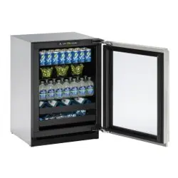
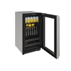
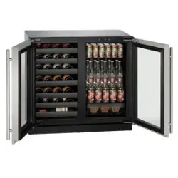
When properly loaded, your U-Line unit will store up to
123 (12 oz. [330 ml]) cans or 79 (12 oz. [330 ml]) bottles
and 31 (750 ml) bottles of wine.
Door Removed For Illustration Purposes
Evaporator cover
Front of unit
Front of unit
Vents (bottom view)
Vents on evaporator cover
Fan (top view)
Fan
2"
2"
1"
1"
21
USER GUIDE
U-Line Wine Guide 1
u-line.com
SAFETY • INSTALLATION & INTEGRATION • OPERATING INSTRUCTIONS • MAINTENANCE • SERVICE
U-Line Wine Guide
LOOKING BEHIND THE LABEL
To most, wine is a delicious mystery. We purchase it,
uncork it, and savor its taste and beauty. But there is so
much more to true wine appreciation. Many secrets are
simply too good to keep bottled up.
WINE SELECTIONS SUGGESTIONS
Selecting the right wine for the right occasion can
sometimes be a seemingly awkward or difficult task for
the beginning wine enthusiast. We would therefore like to
present you with a few suggestions which may provide a
little more confidence and enjoyment when choosing and
serving your wines.
When selecting wines, keep an open mind and do not be
afraid to be adventurous. Do not view the subject of wine
so seriously it discourages you from learning and
discovering for fear of embarrassment if something is
incorrect. Wine is best viewed as a hobby and enjoyed.
When assembling your collection, try not to become
obsessed with “Vintages.” Although a chart can be a useful
tool, generalizations about a specific year have led more
than one collector to disappointment. Often an “Off Year”
will provide a better value and more drinking enjoyment.
The primary guideline to the subject of wine is your own
palate. Do not be afraid to make mistakes. Experiment,
discover, but most of all, enjoy yourself and your new U-
Line product.
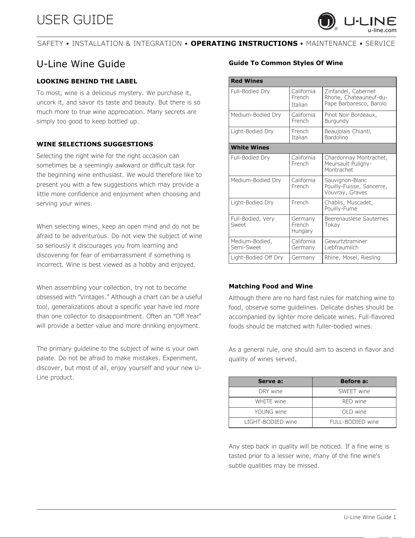
Guide To Common Styles Of Wine
Matching Food and Wine
Although there are no hard fast rules for matching wine to
food, observe some guidelines. Delicate dishes should be
accompanied by lighter more delicate wines. Full-flavored
foods should be matched with fuller-bodied wines.
As a general rule, one should aim to ascend in flavor and
quality of wines served.
Any step back in quality will be noticed. If a fine wine is
tasted prior to a lesser wine, many of the fine wine’s
subtle qualities may be missed.
Red Wines
Full-Bodied Dry California
French
Italian
Zinfandel, Cabernet
Rhone, Chateauneuf-du-
Pape Barbaresco, Barolo
Medium-Bodied Dry California
French
Pinot Noir Bordeaux,
Burgundy
Light-Bodied Dry French
Italian
Beaujolais Chianti,
Bardolino
White Wines
Full-Bodied Dry California
French
Chardonnay Montrachet,
Meursault Puligny-
Montrachet
Medium-Bodied Dry California
French
Sauvignon-Blanc
Pouilly-Fuisse, Sancerre,
Vouvray, Graves
Light-Bodied Dry French Chablis, Muscadet,
Pouilly-Fume
Full-Bodied, Very
Sweet
Germany
French
Hungary
Beerenauslese Sauternes
Tokay
Medium-Bodied,
Semi-Sweet
California
Germany
Gewurtztraminer
Liebfraumilch
Light-Bodied Off Dry Germany Rhine, Mosel, Riesling
Serve a: Before a:
DRY wine SWEET wine
WHITE wine RED wine
YOUNG wine OLD wine
LIGHT-BODIED wine FULL-BODIED wine
22
USER GUIDE
U-Line Wine Guide 2
u-line.com
SAFETY • INSTALLATION & INTEGRATION • OPERATING INSTRUCTIONS • MAINTENANCE • SERVICE
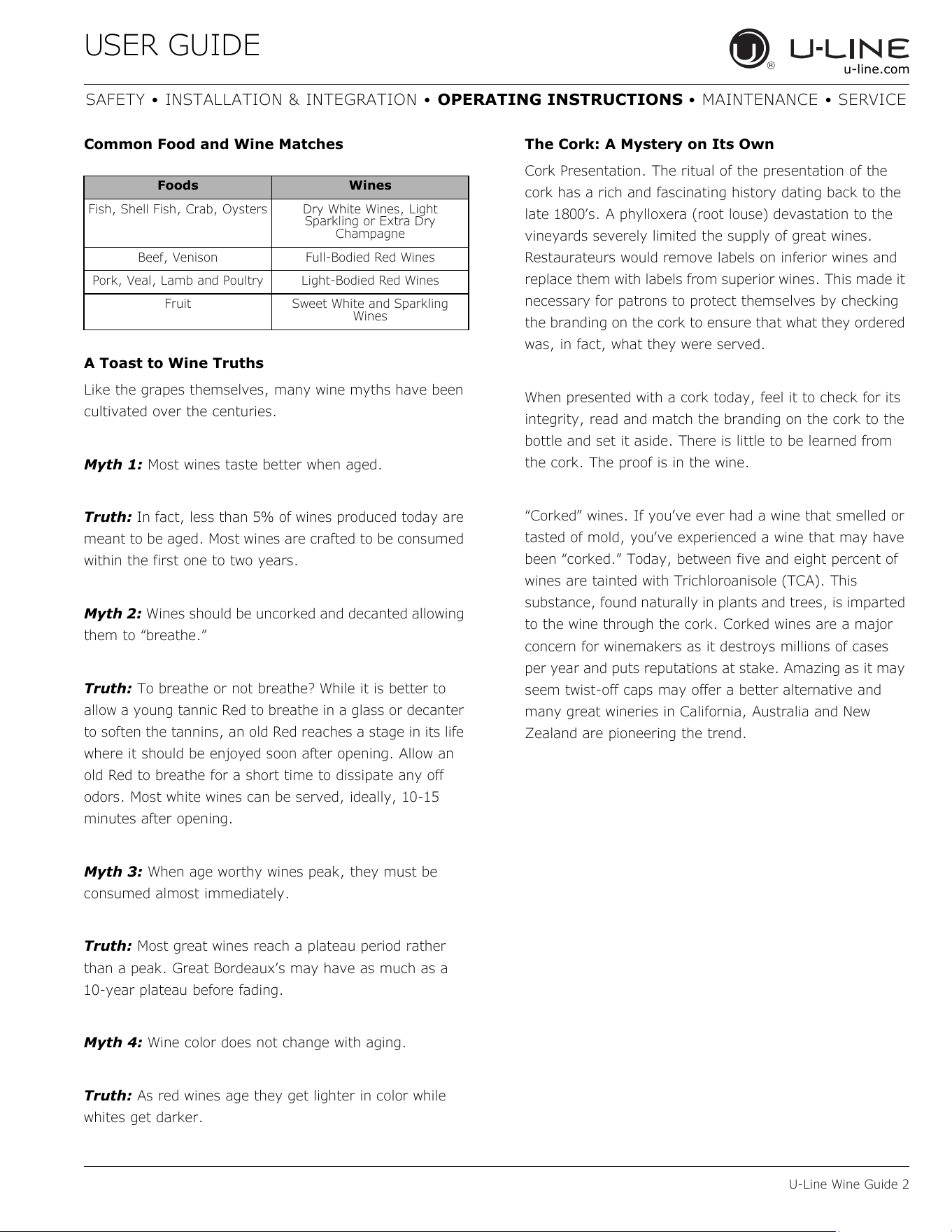
Common Food and Wine Matches
A Toast to Wine Truths
Like the grapes themselves, many wine myths have been
cultivated over the centuries.
Myth 1: Most wines taste better when aged.
Truth: In fact, less than 5% of wines produced today are
meant to be aged. Most wines are crafted to be consumed
within the first one to two years.
Myth 2: Wines should be uncorked and decanted allowing
them to “breathe.”
Truth: To breathe or not breathe? While it is better to
allow a young tannic Red to breathe in a glass or decanter
to soften the tannins, an old Red reaches a stage in its life
where it should be enjoyed soon after opening. Allow an
old Red to breathe for a short time to dissipate any off
odors. Most white wines can be served, ideally, 10-15
minutes after opening.
Myth 3: When age worthy wines peak, they must be
consumed almost immediately.
Truth: Most great wines reach a plateau period rather
than a peak. Great Bordeaux’s may have as much as a
10-year plateau before fading.
Myth 4: Wine color does not change with aging.
Truth: As red wines age they get lighter in color while
whites get darker.
The Cork: A Mystery on Its Own
Cork Presentation. The ritual of the presentation of the
cork has a rich and fascinating history dating back to the
late 1800’s. A phylloxera (root louse) devastation to the
vineyards severely limited the supply of great wines.
Restaurateurs would remove labels on inferior wines and
replace them with labels from superior wines. This made it
necessary for patrons to protect themselves by checking
the branding on the cork to ensure that what they ordered
was, in fact, what they were served.
When presented with a cork today, feel it to check for its
integrity, read and match the branding on the cork to the
bottle and set it aside. There is little to be learned from
the cork. The proof is in the wine.
“Corked” wines. If you’ve ever had a wine that smelled or
tasted of mold, you’ve experienced a wine that may have
been “corked.” Today, between five and eight percent of
wines are tainted with Trichloroanisole (TCA). This
substance, found naturally in plants and trees, is imparted
to the wine through the cork. Corked wines are a major
concern for winemakers as it destroys millions of cases
per year and puts reputations at stake. Amazing as it may
seem twist-off caps may offer a better alternative and
many great wineries in California, Australia and New
Zealand are pioneering the trend.
Foods Wines
Fish, Shell Fish, Crab, Oysters Dry White Wines, Light
Sparkling or Extra Dry
Champagne
Beef, Venison Full-Bodied Red Wines
Pork, Veal, Lamb and Poultry Light-Bodied Red Wines
Fruit Sweet White and Sparkling
Wines
23
USER GUIDE
U-Line Wine Guide 3
u-line.com
SAFETY • INSTALLATION & INTEGRATION • OPERATING INSTRUCTIONS • MAINTENANCE • SERVICE
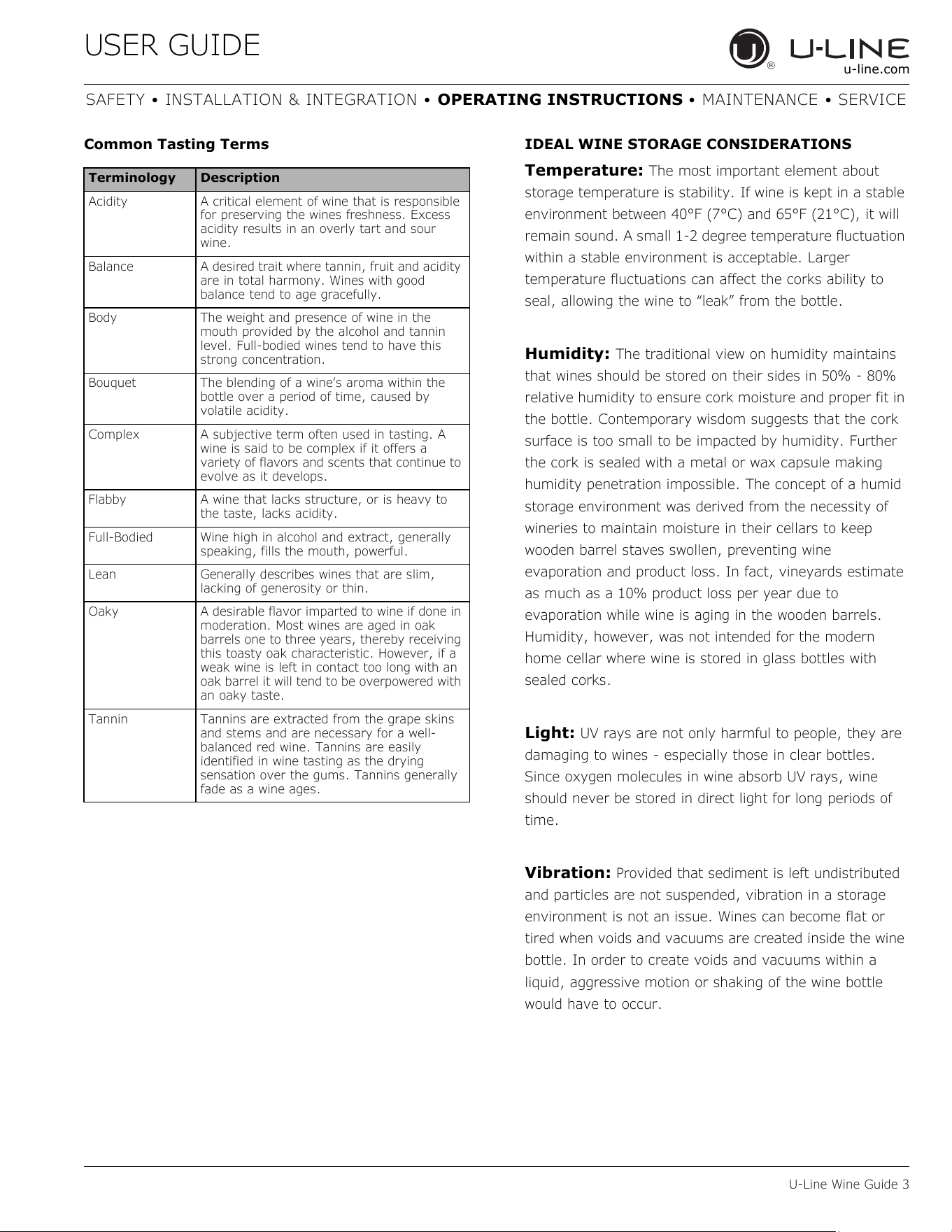
Common Tasting Terms IDEAL WINE STORAGE CONSIDERATIONS
Temperature: The most important element about
storage temperature is stability. If wine is kept in a stable
environment between 40°F (7°C) and 65°F (21°C), it will
remain sound. A small 1-2 degree temperature fluctuation
within a stable environment is acceptable. Larger
temperature fluctuations can affect the corks ability to
seal, allowing the wine to “leak” from the bottle.
Humidity: The traditional view on humidity maintains
that wines should be stored on their sides in 50% - 80%
relative humidity to ensure cork moisture and proper fit in
the bottle. Contemporary wisdom suggests that the cork
surface is too small to be impacted by humidity. Further
the cork is sealed with a metal or wax capsule making
humidity penetration impossible. The concept of a humid
storage environment was derived from the necessity of
wineries to maintain moisture in their cellars to keep
wooden barrel staves swollen, preventing wine
evaporation and product loss. In fact, vineyards estimate
as much as a 10% product loss per year due to
evaporation while wine is aging in the wooden barrels.
Humidity, however, was not intended for the modern
home cellar where wine is stored in glass bottles with
sealed corks.
Light: UV rays are not only harmful to people, they are
damaging to wines - especially those in clear bottles.
Since oxygen molecules in wine absorb UV rays, wine
should never be stored in direct light for long periods of
time.
Vibration: Provided that sediment is left undistributed
and particles are not suspended, vibration in a storage
environment is not an issue. Wines can become flat or
tired when voids and vacuums are created inside the wine
bottle. In order to create voids and vacuums within a
liquid, aggressive motion or shaking of the wine bottle
would have to occur.
Terminology Description
Acidity A critical element of wine that is responsible
for preserving the wines freshness. Excess
acidity results in an overly tart and sour
wine.
Balance A desired trait where tannin, fruit and acidity
are in total harmony. Wines with good
balance tend to age gracefully.
Body The weight and presence of wine in the
mouth provided by the alcohol and tannin
level. Full-bodied wines tend to have this
strong concentration.
Bouquet The blending of a wine’s aroma within the
bottle over a period of time, caused by
volatile acidity.
Complex A subjective term often used in tasting. A
wine is said to be complex if it offers a
variety of flavors and scents that continue to
evolve as it develops.
Flabby A wine that lacks structure, or is heavy to
the taste, lacks acidity.
Full-Bodied Wine high in alcohol and extract, generally
speaking, fills the mouth, powerful.
Lean Generally describes wines that are slim,
lacking of generosity or thin.
Oaky A desirable flavor imparted to wine if done in
moderation. Most wines are aged in oak
barrels one to three years, thereby receiving
this toasty oak characteristic. However, if a
weak wine is left in contact too long with an
oak barrel it will tend to be overpowered with
an oaky taste.
Tannin Tannins are extracted from the grape skins
and stems and are necessary for a well-
balanced red wine. Tannins are easily
identified in wine tasting as the drying
sensation over the gums. Tannins generally
fade as a wine ages.
24
USER GUIDE
U-Line Wine Guide 4
u-line.com
SAFETY • INSTALLATION & INTEGRATION • OPERATING INSTRUCTIONS • MAINTENANCE • SERVICE
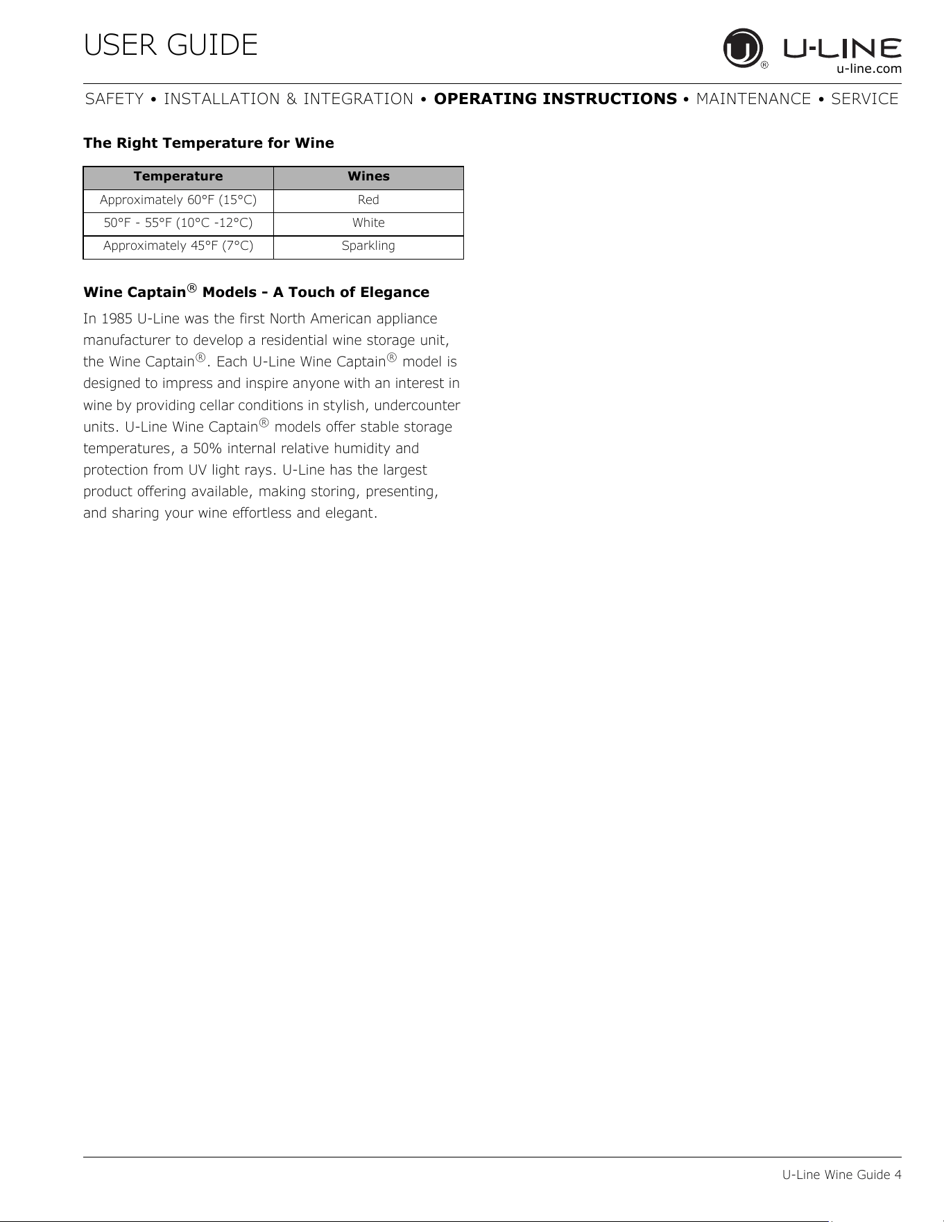
The Right Temperature for Wine
Wine Captain
®
Models - A Touch of Elegance
In 1985 U-Line was the first North American appliance
manufacturer to develop a residential wine storage unit,
the Wine Captain
®
. Each U-Line Wine Captain
®
model is
designed to impress and inspire anyone with an interest in
wine by providing cellar conditions in stylish, undercounter
units. U-Line Wine Captain
®
models offer stable storage
temperatures, a 50% internal relative humidity and
protection from UV light rays. U-Line has the largest
product offering available, making storing, presenting,
and sharing your wine effortless and elegant.
Temperature Wines
Approximately 60°F (15°C) Red
50°F - 55°F (10°C -12°C) White
Approximately 45°F (7°C) Sparkling
25
USER GUIDE
Recommended Wine Storage 1
u-line.com
SAFETY • INSTALLATION & INTEGRATION • OPERATING INSTRUCTIONS • MAINTENANCE • SERVICE
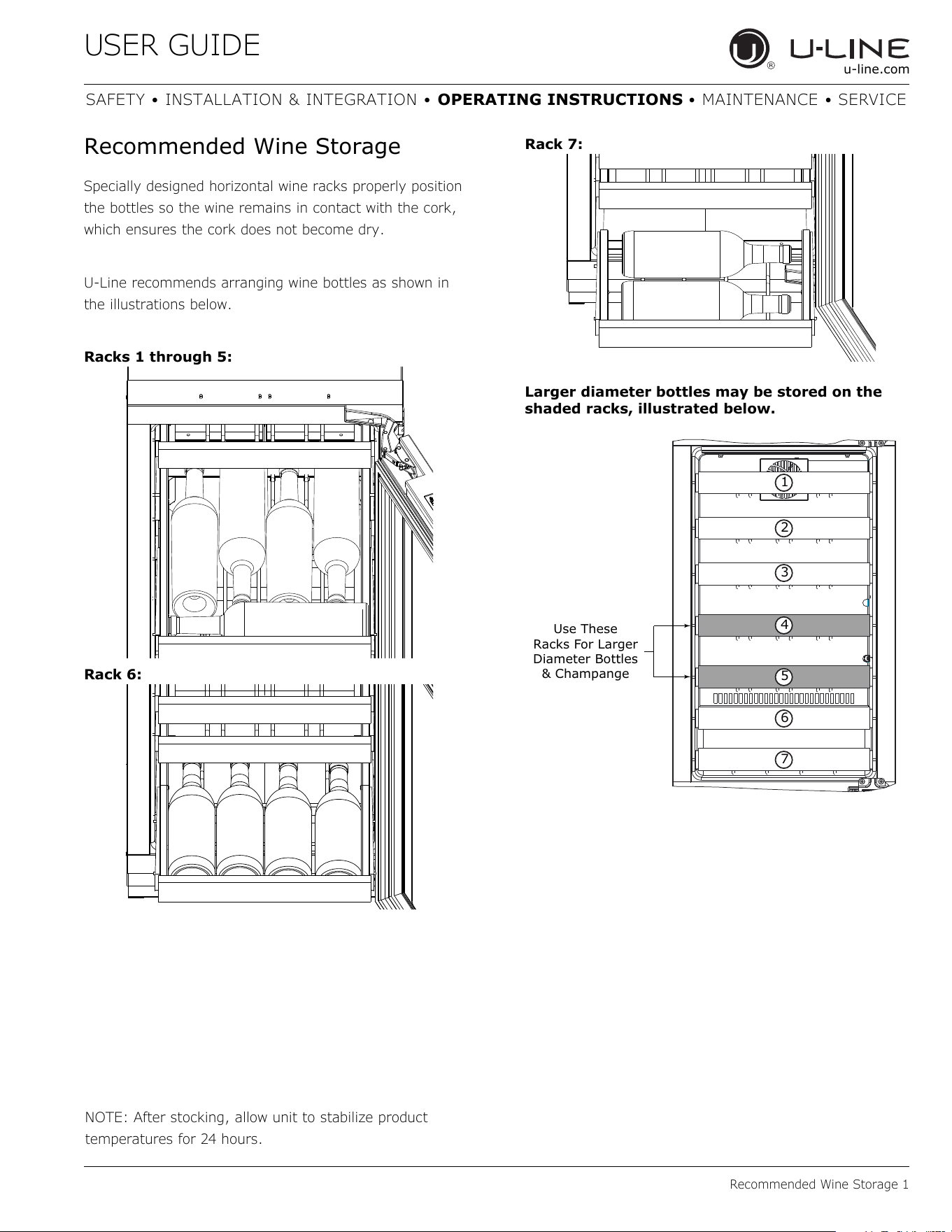
Recommended Wine Storage
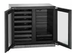
Specially designed horizontal wine racks properly position
the bottles so the wine remains in contact with the cork,
which ensures the cork does not become dry.
U-Line recommends arranging wine bottles as shown in
the illustrations below.
Racks 1 through 5:
Rack 6:
Rack 7:
Larger diameter bottles may be stored on the
shaded racks, illustrated below.
NOTE: After stocking, allow unit to stabilize product
temperatures for 24 hours.
Use These
Racks For Larger
Diameter Bottles
& Champange
1
2
3
4
5
6
7
26
USER GUIDE
Interior Shelves 1
u-line.com
SAFETY • INSTALLATION & INTEGRATION • OPERATING INSTRUCTIONS • MAINTENANCE • SERVICE
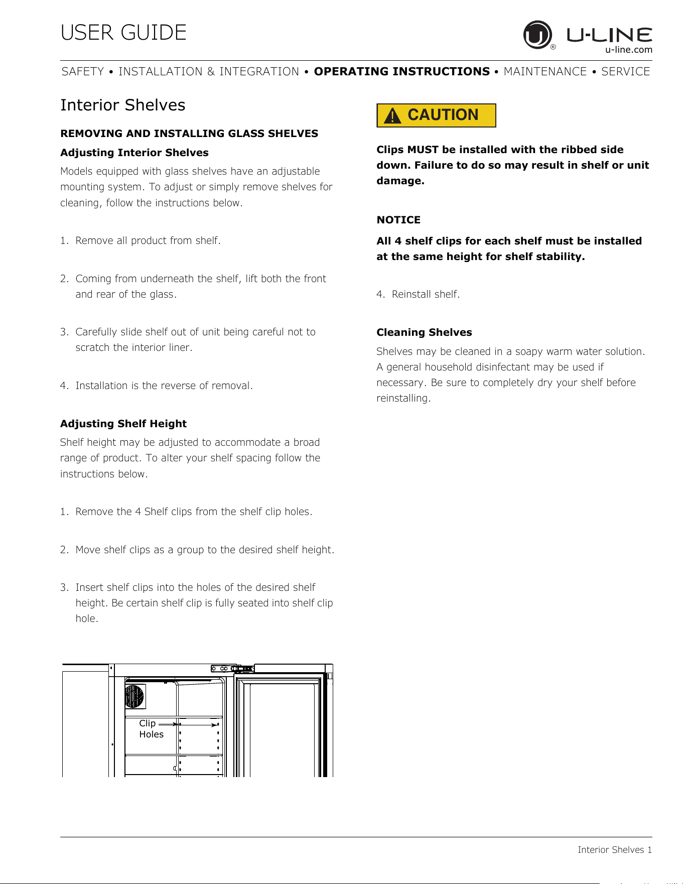
Interior Shelves
REMOVING AND INSTALLING GLASS SHELVES
Adjusting Interior Shelves
Models equipped with glass shelves have an adjustable
mounting system. To adjust or simply remove shelves for
cleaning, follow the instructions below.
1. Remove all product from shelf.
2. Coming from underneath the shelf, lift both the front
and rear of the glass.
3. Carefully slide shelf out of unit being careful not to
scratch the interior liner.
4. Installation is the reverse of removal.
Adjusting Shelf Height
Shelf height may be adjusted to accommodate a broad
range of product. To alter your shelf spacing follow the
instructions below.
1. Remove the 4 Shelf clips from the shelf clip holes.
2. Move shelf clips as a group to the desired shelf height.
3. Insert shelf clips into the holes of the desired shelf
height. Be certain shelf clip is fully seated into shelf clip
hole.
CAUTION
!
Clips MUST be installed with the ribbed side
down. Failure to do so may result in shelf or unit
damage.
NOTICE
All 4 shelf clips for each shelf must be installed
at the same height for shelf stability.
4. Reinstall shelf.
Cleaning Shelves
Shelves may be cleaned in a soapy warm water solution.
A general household disinfectant may be used if
necessary. Be sure to completely dry your shelf before
reinstalling.
Clip
Holes
27
USER GUIDE
Cleaning 1
u-line.com
SAFETY • INSTALLATION & INTEGRATION • OPERATING INSTRUCTIONS • MAINTENANCE • SERVICE
Cleaning
EXTERIOR CLEANING
Stainless Models
Stainless door panels and handles can discolor when
exposed to chlorine gas, pool chemicals, saltwater or
cleaners with bleach.
Keep your stainless unit looking new by cleaning with a
good quality all-in-one stainless steel cleaner and polish
monthly. For best results use Claire
®
Stainless Steel
Polish and Cleaner. Comparable products are acceptable.
Frequent cleaning will remove surface contamination that
could lead to rust. Some installations may require cleaning
weekly.
Do not clean with steel wool pads.
Do not use stainless steel cleaners or polishes on
any glass surfaces.
Clean any glass surfaces with a non-chlorine glass
cleaner.
Do not use cleaners not specifically intended for
stainless steel on stainless steel surfaces (this
includes glass, tile and counter cleaners).
If any surface discoloring or rusting appears, clean it
quickly with Bon-Ami
®
or Barkeepers Friend Cleanser
®
and a nonabrasive cloth. Always clean with the grain.
Always finish with Claire
®
Stainless Steel Polish and
Cleaner or comparable product to prevent further
problems.
Using abrasive pads such as Scotchbrite™ will
cause the graining in the stainless steel to
become blurred.
Rust not cleaned up promptly can penetrate the
surface of the stainless steel and complete
removal of the rust may not be possible.
Integrated Models
To clean integrated panels, use household cleaner per the
cabinet manufacturer’s recommendation.
INTERIOR CLEANING
Disconnect power to the unit.
Clean the interior and all removed components using a
mild nonabrasive detergent and warm water solution
applied with a soft sponge or non-abrasive cloth.
Rinse the interior using a soft sponge and clean water.
Do not use any solvent-based or abrasive
cleaners. These types of cleaners may transfer taste to
the interior products and damage or discolor the lining.
DEFROSTING
Under normal conditions this unit does not require manual
defrosting. Minor frost on the rear wall or visible through
the evaporator plate vents is normal and will melt during
each off cycle.
If there is excessive build-up of 1/4" (6 mm) or more,
manually defrost the unit.
Ensure the door is closing and sealing properly.
High ambient temperature and excessive humidity can
also produce frost.
CAUTION
!
DO NOT use an ice pick or other sharp
instrument to help speed up defrosting. These
instruments can puncture the inner lining or
damage the cooling unit. DO NOT use any type of
heater to defrost. Using a heater to speed up
defrosting can cause personal injury and
damage to the inner lining.
28
USER GUIDE
Cleaning 2
u-line.com
SAFETY • INSTALLATION & INTEGRATION • OPERATING INSTRUCTIONS • MAINTENANCE • SERVICE
NOTICE
The drain pan was not designed to capture the
water created when manually defrosting. To
prevent water from overflowing the drain pan
and possibly damaging water sensitive flooring,
the unit must be removed from cabinetry.
To defrost:
1. Disconnect power to the unit.
2. Remove all products from the interior.
3. Prop the door in an open position (2 in. [50 mm]
minimum).
4. Allow the frost to melt naturally.
5. After the frost melts completely clean the interior and
all removed components. (See INTERIOR CLEANING).
6. When the interior is dry, reconnect power and turn unit
on.
29
USER GUIDE
Cleaning Condenser 1
u-line.com
SAFETY • INSTALLATION & INTEGRATION • OPERATING INSTRUCTIONS • MAINTENANCE • SERVICE
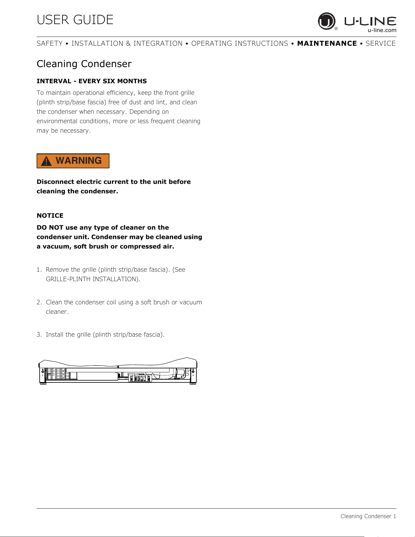
Cleaning Condenser
INTERVAL - EVERY SIX MONTHS
To maintain operational efficiency, keep the front grille
(plinth strip/base fascia) free of dust and lint, and clean
the condenser when necessary. Depending on
environmental conditions, more or less frequent cleaning
may be necessary.
WARNING
!
Disconnect electric current to the unit before
cleaning the condenser.
NOTICE
DO NOT use any type of cleaner on the
condenser unit. Condenser may be cleaned using
a vacuum, soft brush or compressed air.
1. Remove the grille (plinth strip/base fascia). (See
GRILLE-PLINTH INSTALLATION).
2. Clean the condenser coil using a soft brush or vacuum
cleaner.
3. Install the grille (plinth strip/base fascia).
30
USER GUIDE
Wine Rack Installation 1
u-line.com
SAFETY • INSTALLATION & INTEGRATION • OPERATING INSTRUCTIONS • MAINTENANCE • SERVICE
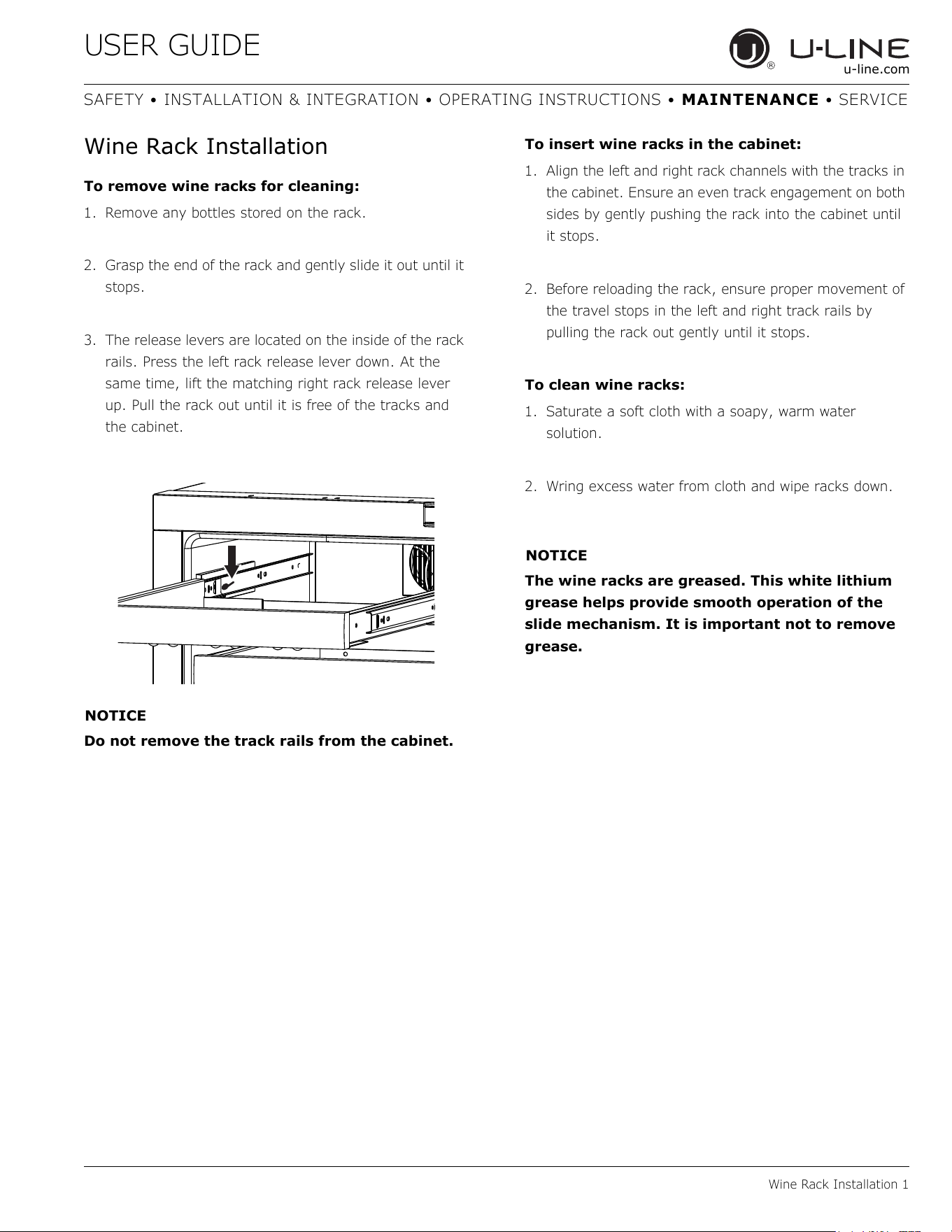
Wine Rack Installation
To remove wine racks for cleaning:
1. Remove any bottles stored on the rack.
2. Grasp the end of the rack and gently slide it out until it
stops.
3. The release levers are located on the inside of the rack
rails. Press the left rack release lever down. At the
same time, lift the matching right rack release lever
up. Pull the rack out until it is free of the tracks and
the cabinet.
NOTICE
Do not remove the track rails from the cabinet.
To insert wine racks in the cabinet:
1. Align the left and right rack channels with the tracks in
the cabinet. Ensure an even track engagement on both
sides by gently pushing the rack into the cabinet until
it stops.
2. Before reloading the rack, ensure proper movement of
the travel stops in the left and right track rails by
pulling the rack out gently until it stops.
To clean wine racks:
1. Saturate a soft cloth with a soapy, warm water
solution.
2. Wring excess water from cloth and wipe racks down.
NOTICE
The wine racks are greased. This white lithium
grease helps provide smooth operation of the
slide mechanism. It is important not to remove
grease.
31
USER GUIDE
Extended Non-Use 1
u-line.com
SAFETY • INSTALLATION & INTEGRATION • OPERATING INSTRUCTIONS • MAINTENANCE • SERVICE
Extended Non-Use
VACATION/HOLIDAY, PROLONGED SHUTDOWN
The following steps are recommended for periods of
extended non-use:
1. Remove all consumable content from the unit.
2. Disconnect the power cord from its outlet/socket and
leave it disconnected until the unit is returned to
service.
3. If ice is on the evaporator, allow ice to thaw naturally.
4. Clean and dry the interior of the unit. Ensure all water
has been removed from the unit.
5. The door must remain open to prevent formation of
mold and mildew. Open door a minimum of 2"
(50 mm) to provide the necessary ventilation.
WINTERIZATION
If the unit will be exposed to temperatures of 40°F (5°C)
or less, the steps above must be followed.
For questions regarding winterization, please
call U-Line at +1.800.779.2547.
CAUTION
!
Damage caused by freezing temperatures is not
covered by the warranty.
32
USER GUIDE
Troubleshooting 1
u-line.com
SAFETY • INSTALLATION & INTEGRATION • OPERATING INSTRUCTIONS • MAINTENANCE • SERVICE
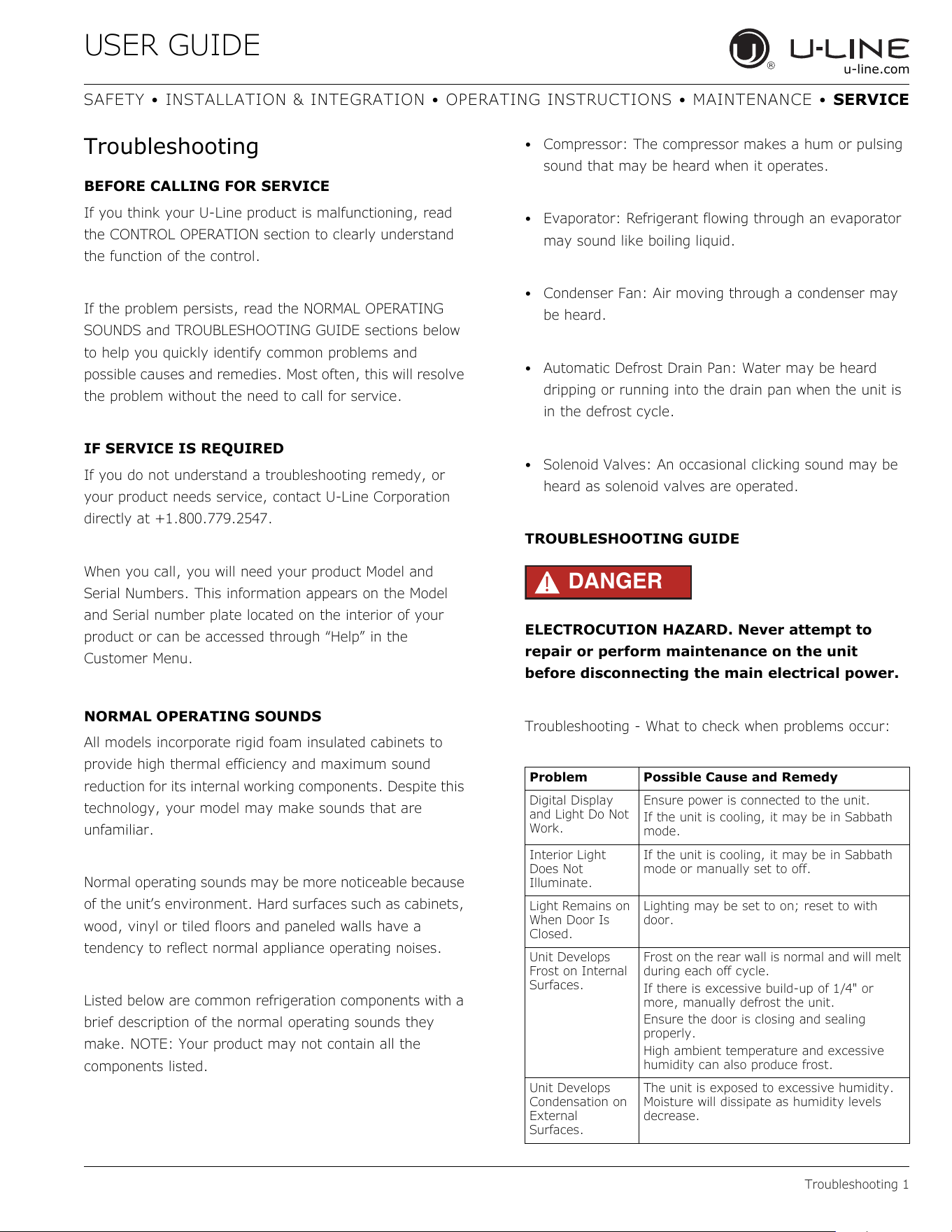
Troubleshooting
BEFORE CALLING FOR SERVICE
If you think your U-Line product is malfunctioning, read
the CONTROL OPERATION section to clearly understand
the function of the control.
If the problem persists, read the NORMAL OPERATING
SOUNDS and TROUBLESHOOTING GUIDE sections below
to help you quickly identify common problems and
possible causes and remedies. Most often, this will resolve
the problem without the need to call for service.
IF SERVICE IS REQUIRED
If you do not understand a troubleshooting remedy, or
your product needs service, contact U-Line Corporation
directly at +1.800.779.2547.
When you call, you will need your product Model and
Serial Numbers. This information appears on the Model
and Serial number plate located on the interior of your
product or can be accessed through “Help” in the
Customer Menu.
NORMAL OPERATING SOUNDS
All models incorporate rigid foam insulated cabinets to
provide high thermal efficiency and maximum sound
reduction for its internal working components. Despite this
technology, your model may make sounds that are
unfamiliar.
Normal operating sounds may be more noticeable because
of the unit’s environment. Hard surfaces such as cabinets,
wood, vinyl or tiled floors and paneled walls have a
tendency to reflect normal appliance operating noises.
Listed below are common refrigeration components with a
brief description of the normal operating sounds they
make. NOTE: Your product may not contain all the
components listed.
• Compressor: The compressor makes a hum or pulsing
sound that may be heard when it operates.
• Evaporator: Refrigerant flowing through an evaporator
may sound like boiling liquid.
• Condenser Fan: Air moving through a condenser may
be heard.
• Automatic Defrost Drain Pan: Water may be heard
dripping or running into the drain pan when the unit is
in the defrost cycle.
• Solenoid Valves: An occasional clicking sound may be
heard as solenoid valves are operated.
TROUBLESHOOTING GUIDE
DANGER
!
ELECTROCUTION HAZARD. Never attempt to
repair or perform maintenance on the unit
before disconnecting the main electrical power.
Troubleshooting - What to check when problems occur:
Problem Possible Cause and Remedy
Digital Display
and Light Do Not
Work.
Ensure power is connected to the unit.
If the unit is cooling, it may be in Sabbath
mode.
Interior Light
Does Not
Illuminate.
If the unit is cooling, it may be in Sabbath
mode or manually set to off.
Light Remains on
When Door Is
Closed.
Lighting may be set to on; reset to with
door.
Unit Develops
Frost on Internal
Surfaces.
Frost on the rear wall is normal and will melt
during each off cycle.
If there is excessive build-up of 1/4" or
more, manually defrost the unit.
Ensure the door is closing and sealing
properly.
High ambient temperature and excessive
humidity can also produce frost.
Unit Develops
Condensation on
External
Surfaces.
The unit is exposed to excessive humidity.
Moisture will dissipate as humidity levels
decrease.
33
USER GUIDE
Troubleshooting 2
u-line.com
SAFETY • INSTALLATION & INTEGRATION • OPERATING INSTRUCTIONS • MAINTENANCE • SERVICE
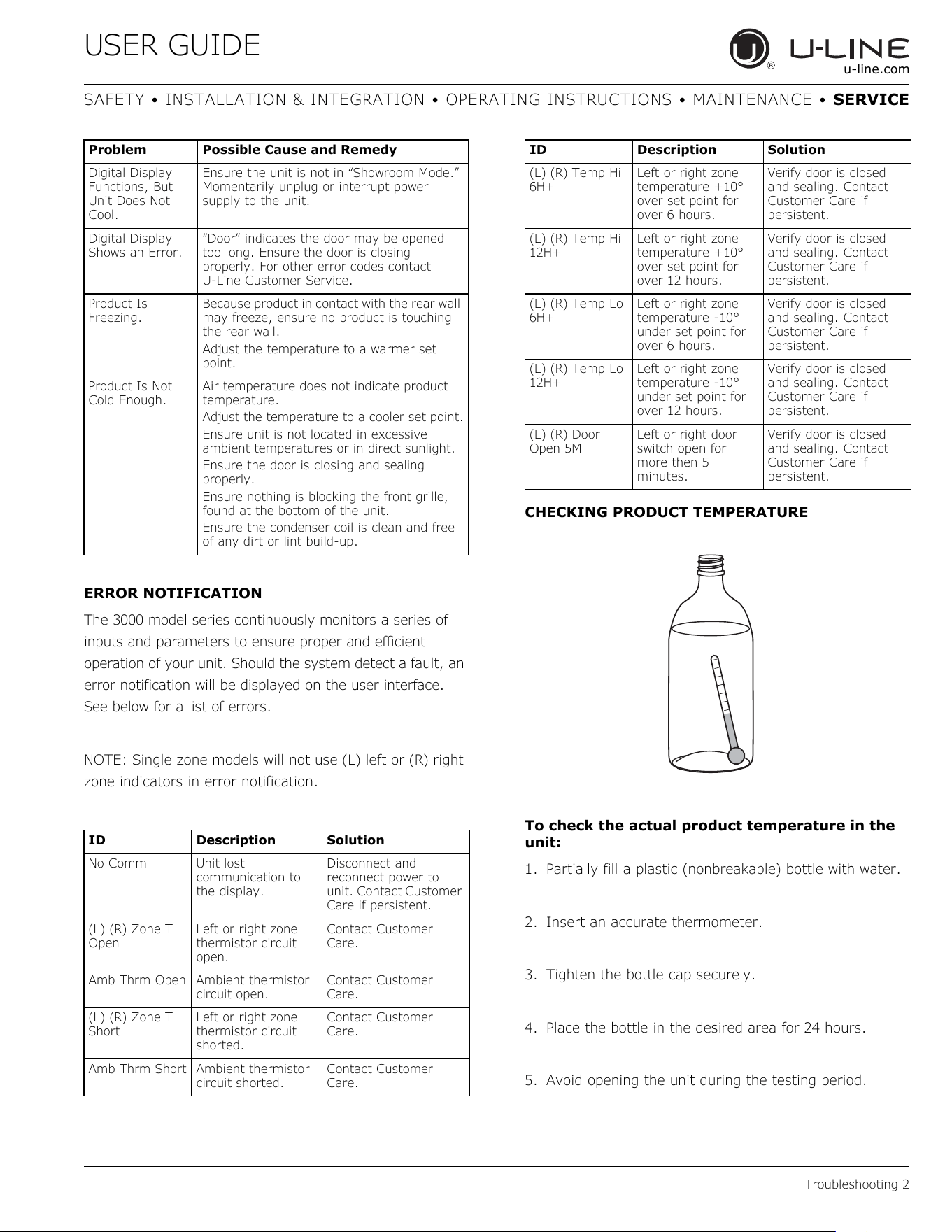
ERROR NOTIFICATION
The 3000 model series continuously monitors a series of
inputs and parameters to ensure proper and efficient
operation of your unit. Should the system detect a fault, an
error notification will be displayed on the user interface.
See below for a list of errors.
NOTE: Single zone models will not use (L) left or (R) right
zone indicators in error notification.
CHECKING PRODUCT TEMPERATURE
To check the actual product temperature in the
unit:
1. Partially fill a plastic (nonbreakable) bottle with water.
2. Insert an accurate thermometer.
3. Tighten the bottle cap securely.
4. Place the bottle in the desired area for 24 hours.
5. Avoid opening the unit during the testing period.
Digital Display
Functions, But
Unit Does Not
Cool.
Ensure the unit is not in “Showroom Mode.”
Momentarily unplug or interrupt power
supply to the unit.
Digital Display
Shows an Error.
“Door” indicates the door may be opened
too long. Ensure the door is closing
properly. For other error codes contact
U-Line Customer Service.
Product Is
Freezing.
Because product in contact with the rear wall
may freeze, ensure no product is touching
the rear wall.
Adjust the temperature to a warmer set
point.
Product Is Not
Cold Enough.
Air temperature does not indicate product
temperature.
Adjust the temperature to a cooler set point.
Ensure unit is not located in excessive
ambient temperatures or in direct sunlight.
Ensure the door is closing and sealing
properly.
Ensure nothing is blocking the front grille,
found at the bottom of the unit.
Ensure the condenser coil is clean and free
of any dirt or lint build-up.
ID Description Solution
No Comm Unit lost
communication to
the display.
Disconnect and
reconnect power to
unit. Contact Customer
Care if persistent.
(L) (R) Zone T
Open
Left or right zone
thermistor circuit
open.
Contact Customer
Care.
Amb Thrm Open Ambient thermistor
circuit open.
Contact Customer
Care.
(L) (R) Zone T
Short
Left or right zone
thermistor circuit
shorted.
Contact Customer
Care.
Amb Thrm Short Ambient thermistor
circuit shorted.
Contact Customer
Care.
Problem Possible Cause and Remedy
(L) (R) Temp Hi
6H+
Left or right zone
temperature +10°
over set point for
over 6 hours.
Verify door is closed
and sealing. Contact
Customer Care if
persistent.
(L) (R) Temp Hi
12H+
Left or right zone
temperature +10°
over set point for
over 12 hours.
Verify door is closed
and sealing. Contact
Customer Care if
persistent.
(L) (R) Temp Lo
6H+
Left or right zone
temperature -10°
under set point for
over 6 hours.
Verify door is closed
and sealing. Contact
Customer Care if
persistent.
(L) (R) Temp Lo
12H+
Left or right zone
temperature -10°
under set point for
over 12 hours.
Verify door is closed
and sealing. Contact
Customer Care if
persistent.
(L) (R) Door
Open 5M
Left or right door
switch open for
more then 5
minutes.
Verify door is closed
and sealing. Contact
Customer Care if
persistent.
ID Description Solution
34
USER GUIDE
Troubleshooting 3
u-line.com
SAFETY • INSTALLATION & INTEGRATION • OPERATING INSTRUCTIONS • MAINTENANCE • SERVICE
6. After 24 hours, check the temperature of the water. If
required, adjust the temperature control in a small
increment (see CONTROL OPERATION).
Causes which affect the internal temperatures of
the cabinet include:
• Temperature setting.
• Ambient temperature where installed.
• Installation in direct sunlight or near a heat source.
• The number of door openings and the time the door is
open.
• The time the internal light is illuminated. (This mainly
affects product on the top rack or shelf.)
• Obstruction of front grille or condenser.
35
USER GUIDE
Wire Diagram 1
u-line.com
SAFETY • INSTALLATION & INTEGRATION • OPERATING INSTRUCTIONS • MAINTENANCE • SERVICE
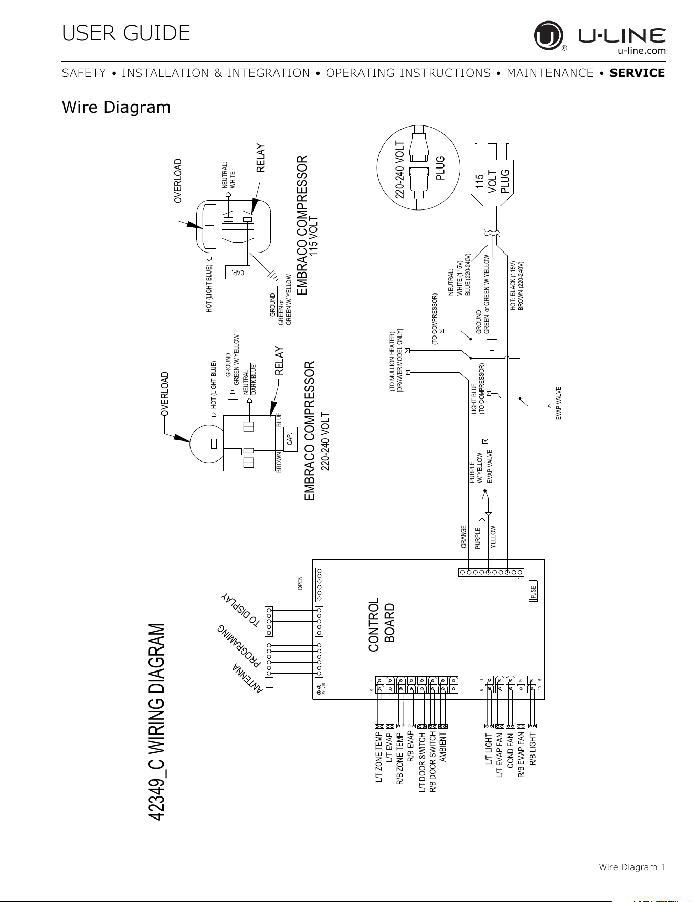
Wire Diagram
42349_C WIRING DIAGRAM
115
VOLT
PLUG
220-240 VOLT
PLUG
GROUND:
GREEN or GREEN W/ YELLOW
HOT: BLACK (115V)
BROWN (220-240V)
NEUTRAL:
WHITE (115V)
BLUE (220-240V)
(TO COMPRESSOR)
LIGHT BLUE
(TO COMPRESSOR)
PURPLE
W/ YELLOW
PURPLE
YELLOW
EVAP VALVE
EVAP VALVE
1
10
CONTROL
BOARD
L/T ZONE TEMP
9
1
L/T EVAP
L/T DOOR SWITCH
AMBIENT
R/B DOOR SWITCH
FUSE
6
1
10
5
R/B LIGHT
L/T LIGHT
COND FAN
L/T EVAP FAN
R/B EVAP FAN
R/B ZONE TEMP
R/B EVAP
PROGRAMING
TO DISPLAY
OPEN
ANTENNA
J9
J10
NEUTRAL:
WHITE
HOT (LIGHT BLUE)
RELAY
EMBRACO COMPRESSOR
GREEN or
GREEN W/ YELLOW
GROUND:
OVERLOAD
115 VOLT
HOT (LIGHT BLUE)
OVERLOAD
EMBRACO COMPRESSOR
220-240 VOLT
RELAY
GREEN W/ YELLOW
GROUND:
NEUTRAL:
DARK BLUE
CAP.
CAP.
BROWN BLUE
(TO MULLION HEATER)
ORANGE
[DRAWER MODEL ONLY]
36
USER GUIDE
Product Liability 1
u-line.com
SAFETY • INSTALLATION & INTEGRATION • OPERATING INSTRUCTIONS • MAINTENANCE • SERVICE
Product Liability
Field service technicians are authorized to make an initial
assessment in the event of reported damages. If there are
any questions about the process involved, the technician
should call U-Line for further explanation.
While inspecting for defects or installation issues, photos
should be taken to document any damages or issues
found.
During the assessment, if the service technician is able to
find the source of the damage and it can be resolved by
replacement of a part, the servicer is authorized to
replace the part in question. The part that caused the
damage must be returned to U-Line in its entirety. The
part must be clearly labeled with the serial number of the
unit it was removed from, the date, and the servicer who
removed the part.
If the service technician determines the damage is the
result of installation issues (water connection/drain, etc.),
the consumer would be notified and the issues shall be
resolved at the direction of the consumer.
If damage is evident and the service technician is unable
to find the source, U-Line must be contacted at 1-800-
799-2547 for further direction
8900 N. 55th Street • Milwaukee, WI 53223
T: +1.414.354.0300 • F: +1.414.354.354.5696
Website: www.u-line.com
Right product. Right place.
Right temperature Since 1962.
37
USER GUIDE
Warranty Claims 1
u-line.com
SAFETY • INSTALLATION & INTEGRATION • OPERATING INSTRUCTIONS • MAINTENANCE • SERVICE
Warranty Claims
The following information defines the parameters for filing
a warranty claim:
• Valid serial number needed
• Valid model number needed
• Narda (or equivalent) form or submitted online at
www.u-line.com
• 60 day submittal deadline from date of completed
service
• Only one repair or unit per warranty claim
• Refrigerant should be labeled and included on the labor
submittal
• Door and water level adjustments are covered 30 days
from install date.
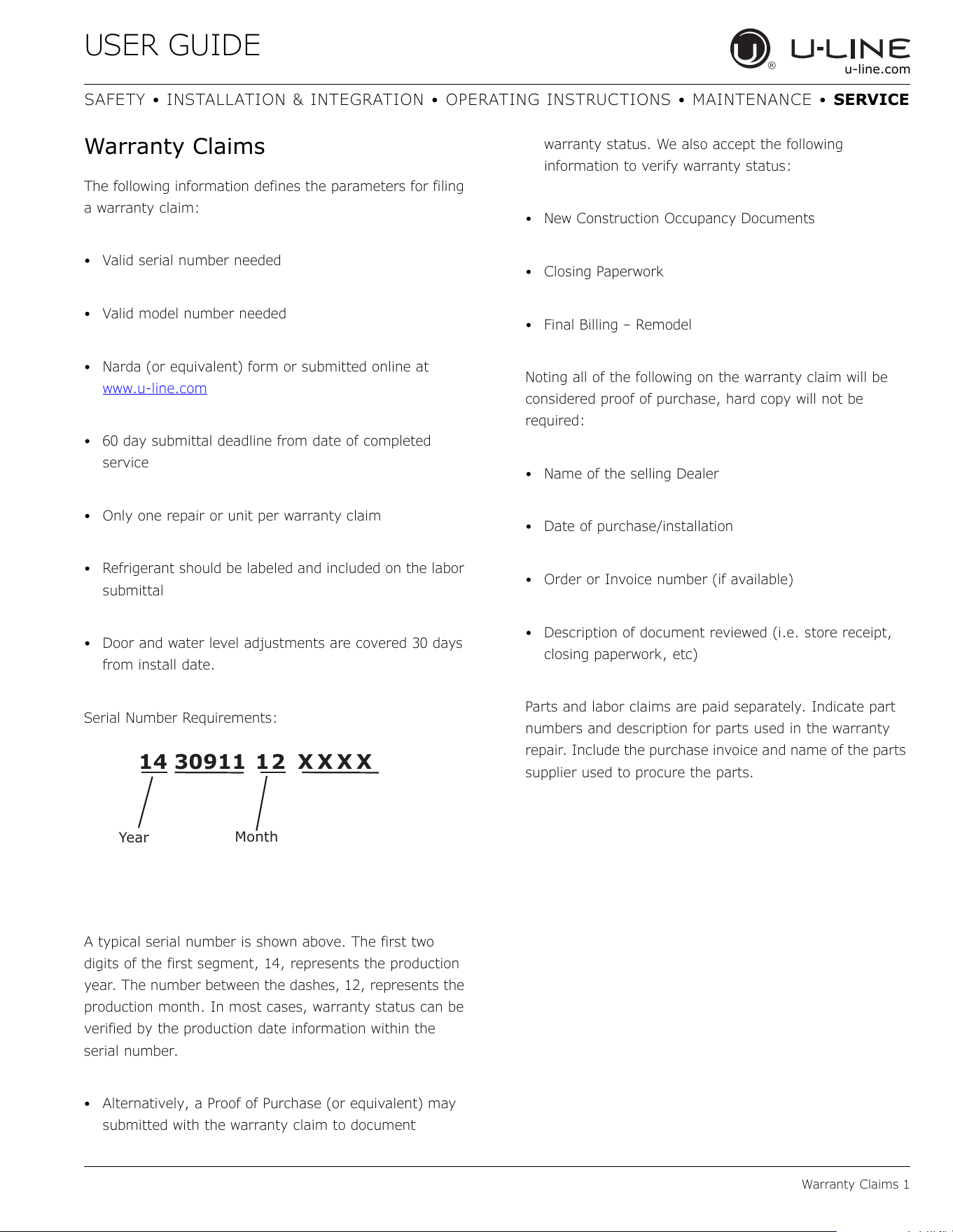
Serial Number Requirements:
A typical serial number is shown above. The first two
digits of the first segment, 14, represents the production
year. The number between the dashes, 12, represents the
production month. In most cases, warranty status can be
verified by the production date information within the
serial number.
• Alternatively, a Proof of Purchase (or equivalent) may
submitted with the warranty claim to document
warranty status. We also accept the following
information to verify warranty status:
• New Construction Occupancy Documents
•Closing Paperwork
• Final Billing – Remodel
Noting all of the following on the warranty claim will be
considered proof of purchase, hard copy will not be
required:
• Name of the selling Dealer
• Date of purchase/installation
• Order or Invoice number (if available)
• Description of document reviewed (i.e. store receipt,
closing paperwork, etc)
Parts and labor claims are paid separately. Indicate part
numbers and description for parts used in the warranty
repair. Include the purchase invoice and name of the parts
supplier used to procure the parts.
14 30911 12 XXXX
Year
Month
38
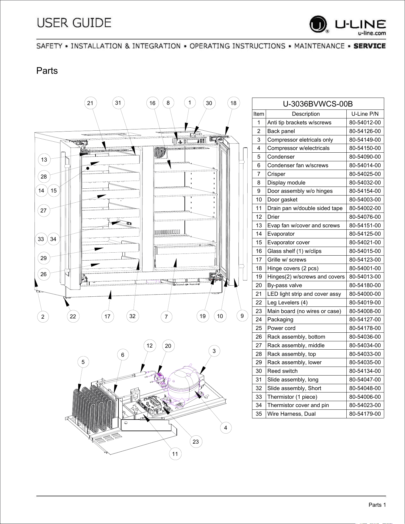
U-3036BVWCS-00B
Item Description U-Line P/N
1 Anti tip brackets w/screws 80-54012-00
2 Back panel 80-54126-00
3 Compressor eletricals only 80-54149-00
4 Compressor w/electricals 80-54150-00
5 Condenser 80-54090-00
6 Condenser fan w/screws 80-54014-00
7 Crisper 80-54025-00
8 Display module 80-54032-00
9 Door assembly w/o hinges 80-54154-00
10 Door gasket 80-54003-00
11 Drain pan w/double sided tape 80-54002-00
12 Drier 80-54076-00
13 Evap fan w/cover and screws 80-54151-00
14 Evaporator 80-54125-00
15 Evaporator cover 80-54021-00
16 Glass shelf (1) w/clips 80-54015-00
17 Grille w/ screws 80-54123-00
18 Hinge covers (2 pcs) 80-54001-00
19 Hinges(2) w/screws and covers 80-54013-00
20 By-pass valve 80-54180-00
21 LED light strip and cover assy 80-54000-00
22 Leg Levelers (4) 80-54019-00
23 Main board (no wires or case) 80-54008-00
24 Packaging 80-54127-00
25 Power cord 80-54178-00
26 Rack assembly, bottom 80-54036-00
27 Rack assembly, middle 80-54034-00
28 Rack assembly, top 80-54033-00
29 Rack assembly, lower 80-54035-00
30 Reed switch 80-54134-00
31 Slide assembly, long 80-54047-00
32 Slide assembly, Short 80-54048-00
33 Thermistor (1 piece) 80-54006-00
34 Thermistor cover and pin 80-54023-00
35 Wire Harness, Dual 80-54179-00
Parts
Parts 1
1
2
7
8
9
10
13
14 15
16
17
18
19
21
22
26
27
28
29
30
31
32
33 34
3
4
5
6
11
12
20
23
39
USER GUIDE
Ordering Replacement Parts 1
u-line.com
SAFETY • INSTALLATION & INTEGRATION • OPERATING INSTRUCTIONS • MAINTENANCE • SERVICE
Ordering Replacement Parts
If you have a purchasing account, please utilize our
service website to order parts.
Orders may also be placed by Fax or phone. See our
contact information below:
www.U-LineService.com (with service login)
FAX Number: +1.414.354.5696
Phone Number: +1.800.779.2547
NOTICE
Use only genuine U-Line replacement parts. The
use of non-U-Line parts can reduce speed of ice
production, cause water to overflow from ice
maker mold, damage the unit, and void the
warranty.
Warranty parts will be shipped at no charge after U-Line
confirms warranty status. Please provide the model, serial
number, part number and part description. Some parts
will require color or voltage information.
If U-Line requires the return of original parts, we will
inform you when the parts order is taken. This
requirement will be noted on your packing list. A prepaid
shipping label will be included with the replacement part.
Please enclose a copy of the parts packing list and any
labor claims with your return. Please be sure the model
and serial numbers are legible on the paperwork. Tag the
part with the reported defect.
When ordering a non-warranty part, you will need an open
account and tax exemption on file at U-Line. Another
option would be to visit www.u-line.com to locate an
authorized parts distributor in your area.
40
USER GUIDE
R-600A Specifications 1
u-line.com
SAFETY • INSTALLATION & INTEGRATION • OPERATING INSTRUCTIONS • MAINTENANCE • SERVICE
R-600A Specifications
For R-600a refrigerant service tips and more videos, go
to: www.u-line.com/videos
.
WARNING
!
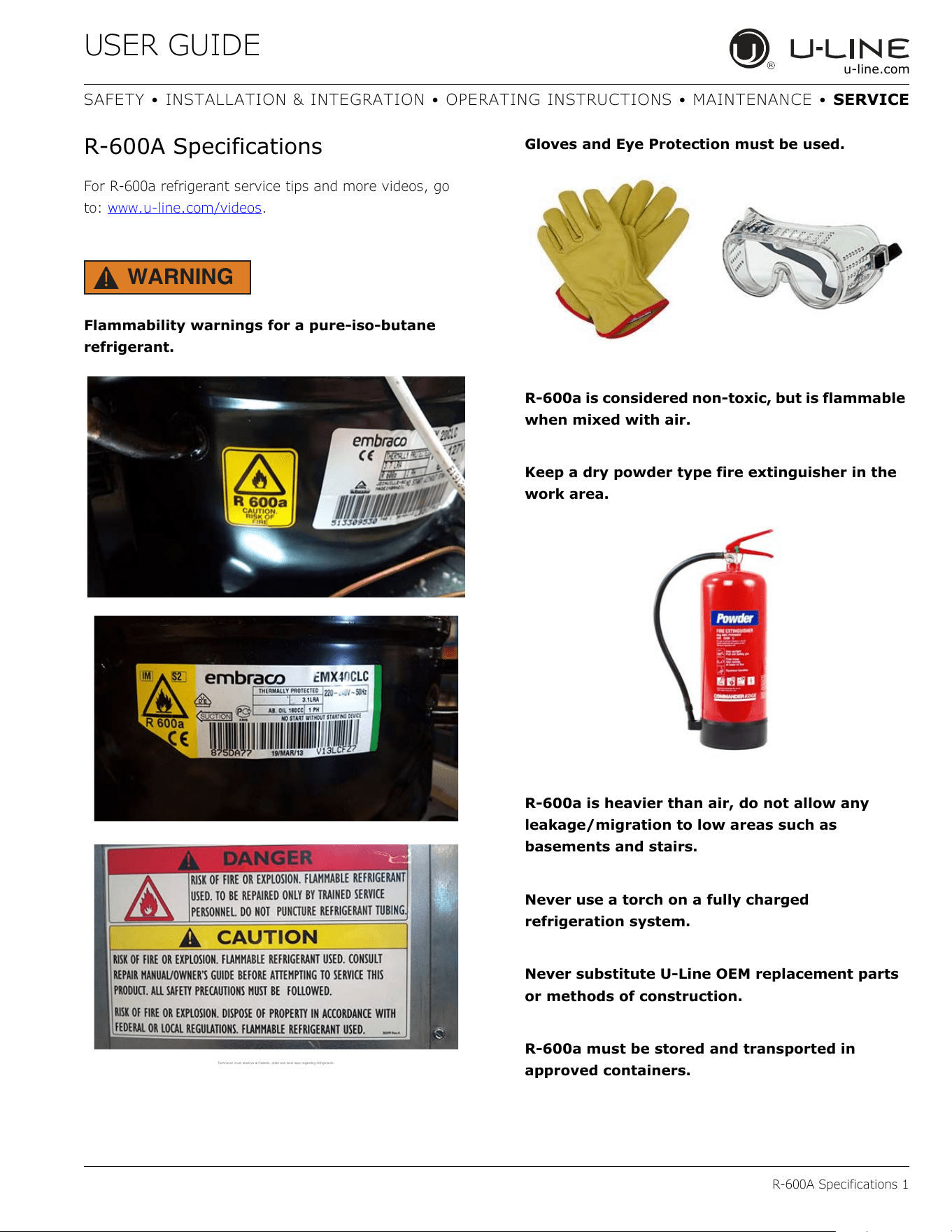
Flammability warnings for a pure-iso-butane
refrigerant.
Technician m ust observe al l federal, st ate and local la ws regarding refrigerants .
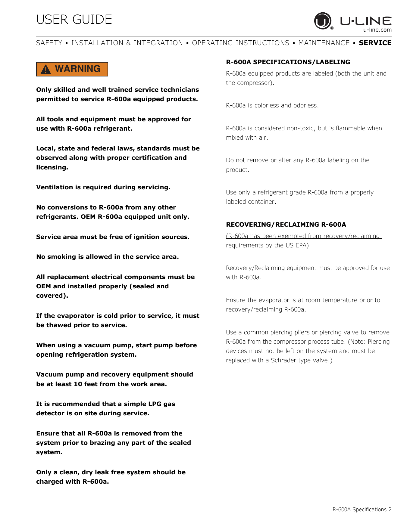
Gloves and Eye Protection must be used.
R-600a is considered non-toxic, but is flammable
when mixed with air.
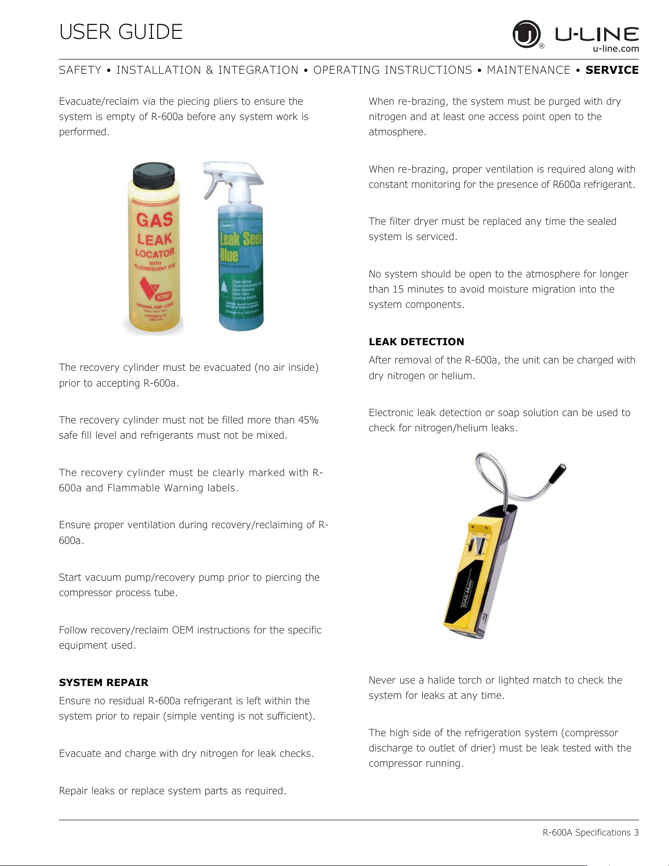
Keep a dry powder type fire extinguisher in the
work area.
R-600a is heavier than air, do not allow any
leakage/migration to low areas such as
basements and stairs.
Never use a torch on a fully charged
refrigeration system.
Never substitute U-Line OEM replacement parts
or methods of construction.
R-600a must be stored and transported in
approved containers.
41
USER GUIDE
R-600A Specifications 2
u-line.com
SAFETY • INSTALLATION & INTEGRATION • OPERATING INSTRUCTIONS • MAINTENANCE • SERVICE
WARNING
!
Only skilled and well trained service technicians
permitted to service R-600a equipped products.
All tools and equipment must be approved for
use with R-600a refrigerant.
Local, state and federal laws, standards must be
observed along with proper certification and
licensing.
Ventilation is required during servicing.
No conversions to R-600a from any other
refrigerants. OEM R-600a equipped unit only.
Service area must be free of ignition sources.
No smoking is allowed in the service area.
All replacement electrical components must be
OEM and installed properly (sealed and
covered).
If the evaporator is cold prior to service, it must
be thawed prior to service.
When using a vacuum pump, start pump before
opening refrigeration system.
Vacuum pump and recovery equipment should
be at least 10 feet from the work area.
It is recommended that a simple LPG gas
detector is on site during service.
Ensure that all R-600a is removed from the
system prior to brazing any part of the sealed
system.
Only a clean, dry leak free system should be
charged with R-600a.
R-600A SPECIFICATIONS/LABELING
R-600a equipped products are labeled (both the unit and
the compressor).
R-600a is colorless and odorless.
R-600a is considered non-toxic, but is flammable when
mixed with air.
Do not remove or alter any R-600a labeling on the
product.
Use only a refrigerant grade R-600a from a properly
labeled container.
RECOVERING/RECLAIMING R-600A
(R-600a has been exempted from recovery/reclaiming
requirements by the US EPA)
Recovery/Reclaiming equipment must be approved for use
with R-600a.
Ensure the evaporator is at room temperature prior to
recovery/reclaiming R-600a.
Use a common piercing pliers or piercing valve to remove
R-600a from the compressor process tube. (Note: Piercing
devices must not be left on the system and must be
replaced with a Schrader type valve.)
42
USER GUIDE
R-600A Specifications 3
u-line.com
SAFETY • INSTALLATION & INTEGRATION • OPERATING INSTRUCTIONS • MAINTENANCE • SERVICE
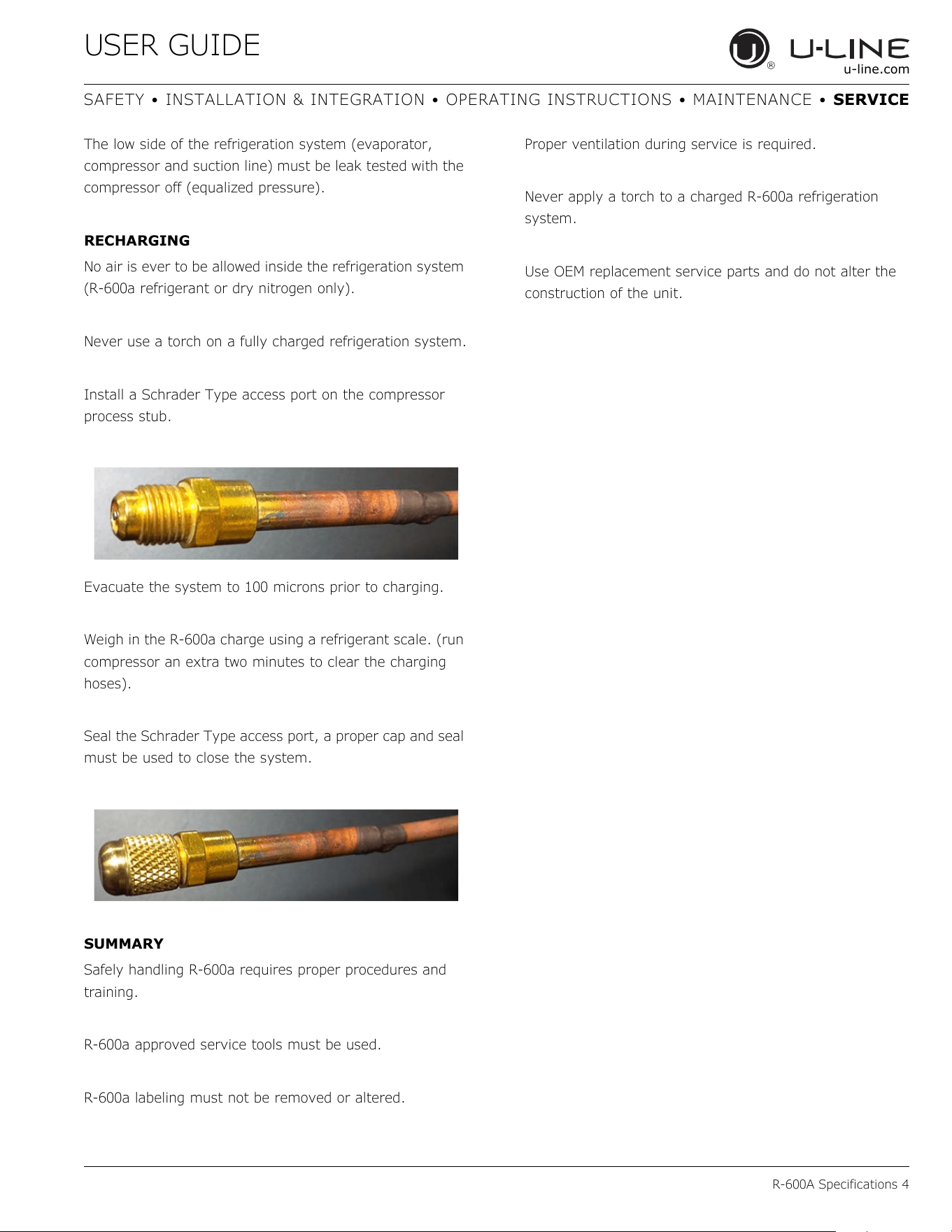
Evacuate/reclaim via the piecing pliers to ensure the
system is empty of R-600a before any system work is
performed.
The recovery cylinder must be evacuated (no air inside)
prior to accepting R-600a.
The recovery cylinder must not be filled more than 45%
safe fill level and refrigerants must not be mixed.
The recovery cylinder must be clearly marked with R-
600a and Flammable Warning labels.
Ensure proper ventilation during recovery/reclaiming of R-
600a.
Start vacuum pump/recovery pump prior to piercing the
compressor process tube.
Follow recovery/reclaim OEM instructions for the specific
equipment used.
SYSTEM REPAIR
Ensure no residual R-600a refrigerant is left within the
system prior to repair (simple venting is not sufficient).
Evacuate and charge with dry nitrogen for leak checks.
Repair leaks or replace system parts as required.
When re-brazing, the system must be purged with dry
nitrogen and at least one access point open to the
atmosphere.
When re-brazing, proper ventilation is required along with
constant monitoring for the presence of R600a refrigerant.
The filter dryer must be replaced any time the sealed
system is serviced.
No system should be open to the atmosphere for longer
than 15 minutes to avoid moisture migration into the
system components.
LEAK DETECTION
After removal of the R-600a, the unit can be charged with
dry nitrogen or helium.
Electronic leak detection or soap solution can be used to
check for nitrogen/helium leaks.
Never use a halide torch or lighted match to check the
system for leaks at any time.
The high side of the refrigeration system (compressor
discharge to outlet of drier) must be leak tested with the
compressor running.
43
USER GUIDE
R-600A Specifications 4
u-line.com
SAFETY • INSTALLATION & INTEGRATION • OPERATING INSTRUCTIONS • MAINTENANCE • SERVICE
The low side of the refrigeration system (evaporator,
compressor and suction line) must be leak tested with the
compressor off (equalized pressure).
RECHARGING
No air is ever to be allowed inside the refrigeration system
(R-600a refrigerant or dry nitrogen only).
Never use a torch on a fully charged refrigeration system.
Install a Schrader Type access port on the compressor
process stub.
Evacuate the system to 100 microns prior to charging.
Weigh in the R-600a charge using a refrigerant scale. (run
compressor an extra two minutes to clear the charging
hoses).
Seal the Schrader Type access port, a proper cap and seal
must be used to close the system.
SUMMARY
Safely handling R-600a requires proper procedures and
training.
R-600a approved service tools must be used.
R-600a labeling must not be removed or altered.
Proper ventilation during service is required.
Never apply a torch to a charged R-600a refrigeration
system.
Use OEM replacement service parts and do not alter the
construction of the unit.
44
USER GUIDE
System Diagnosis Guide 1
u-line.com
SAFETY • INSTALLATION & INTEGRATION • OPERATING INSTRUCTIONS • MAINTENANCE • SERVICE
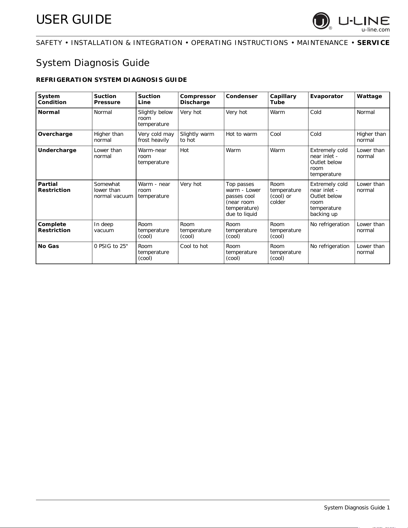
System Diagnosis Guide
REFRIGERATION SYSTEM DIAGNOSIS GUIDE
System
Condition
Suction
Pressure
Suction
Line
Compressor
Discharge
Condenser Capillary
Tube
Evaporator Wattage
Normal Normal Slightly below
room
temperature
Very hot Very hot Warm Cold Normal
Overcharge Higher than
normal
Very cold may
frost heavily
Slightly warm
to hot
Hot to warm Cool Cold Higher than
normal
Undercharge Lower than
normal
Warm-near
room
temperature
Hot Warm Warm Extremely cold
near inlet -
Outlet below
room
temperature
Lower than
normal
Partial
Restriction
Somewhat
lower than
normal vacuum
Warm - near
room
temperature
Very hot Top passes
warm - Lower
passes cool
(near room
temperature)
due to liquid
Room
temperature
(cool) or
colder
Extremely cold
near inlet -
Outlet below
room
temperature
backing up
Lower than
normal
Complete
Restriction
In deep
vacuum
Room
temperature
(cool)
Room
temperature
(cool)
Room
temperature
(cool)
Room
temperature
(cool)
No refrigeration Lower than
normal
No Gas 0 PSIG to 25" Room
temperature
(cool)
Cool to hot Room
temperature
(cool)
Room
temperature
(cool)
No refrigeration Lower than
normal
45
USER GUIDE
Compressor Specifications 1
u-line.com
SAFETY • INSTALLATION & INTEGRATION • OPERATING INSTRUCTIONS • MAINTENANCE • SERVICE
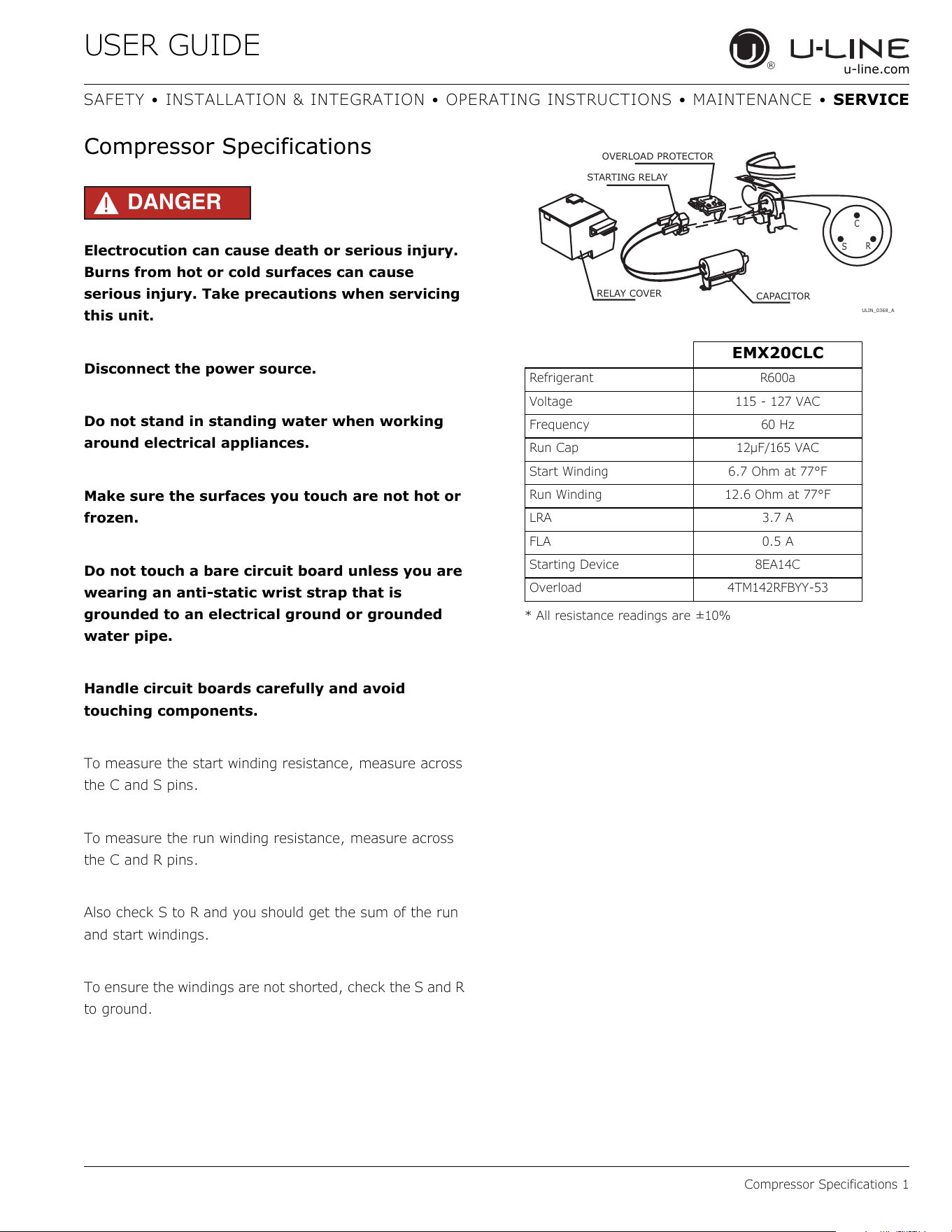
Compressor Specifications
DANGER
!
Electrocution can cause death or serious injury.
Burns from hot or cold surfaces can cause
serious injury. Take precautions when servicing
this unit.
Disconnect the power source.
Do not stand in standing water when working
around electrical appliances.
Make sure the surfaces you touch are not hot or
frozen.
Do not touch a bare circuit board unless you are
wearing an anti-static wrist strap that is
grounded to an electrical ground or grounded
water pipe.
Handle circuit boards carefully and avoid
touching components.
To measure the start winding resistance, measure across
the C and S pins.
To measure the run winding resistance, measure across
the C and R pins.
Also check S to R and you should get the sum of the run
and start windings.
To ensure the windings are not shorted, check the S and R
to ground.
* All resistance readings are ±10%
EMX20CLC
Refrigerant R600a
Voltage 115 - 127 VAC
Frequency 60 Hz
Run Cap 12μF/165 VAC
Start Winding 6.7 Ohm at 77°F
Run Winding 12.6 Ohm at 77°F
LRA 3.7 A
FLA 0.5 A
Starting Device 8EA14C
Overload 4TM142RFBYY-53
C
S
R
OVERLOAD PROTECTOR
STARTING RELAY
CAPACITOR
RELAY COVER
ULIN_0368_A
46
USER GUIDE
Troubleshooting - Extended 1
u-line.com
SAFETY • INSTALLATION & INTEGRATION • OPERATING INSTRUCTIONS • MAINTENANCE • SERVICE
Troubleshooting - Extended
SPECIFIC ERRORS AND ISSUES
The technically advanced diagnostic capabilities of the
electronic controls utilized on the 3000 series units allows
for easy and thorough trouble shooting.
Navigation of the control is the key and is explained in the
CONTROL OPERATION section of the manual, along with
control button layout, control function descriptions, a
service mode menu and service menu selection
explanations.
Verification of temperature and thermistor performance
can be identified by directly viewing actual temperature
readings in the service mode.
Component failure issues can be identified through service
mode menu selection, “Relay Toggle” Individual
components can be switched on and off to check for both
proper function of a specific component and also delivery
of supply voltage to the components through the relays
and DC outputs located on the relay/power board.
Included in this section is some diagnostic tips and as
always, if additional help is required please contact the
U-Line Corp, “Customer Care Facility” at +1.800.779.2547
for assistance.
CAUTION
!
Never attempt to repair or perform maintenance
on the unit until the main electrical power has
been disconnected from the unit.
47
USER GUIDE
Troubleshooting - Extended 2
u-line.com
SAFETY • INSTALLATION & INTEGRATION • OPERATING INSTRUCTIONS • MAINTENANCE • SERVICE
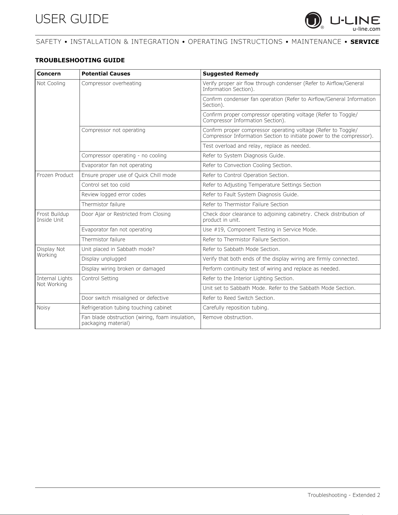
TROUBLESHOOTING GUIDE
Concern Potential Causes Suggested Remedy
Not Cooling Compressor overheating Verify proper air flow through condenser (Refer to Airflow/General
Information Section).
Confirm condenser fan operation (Refer to Airflow/General Information
Section).
Confirm proper compressor operating voltage (Refer to Toggle/
Compressor Information Section).
Compressor not operating Confirm proper compressor operating voltage (Refer to Toggle/
Compressor Information Section to initiate power to the compressor).
Test overload and relay, replace as needed.
Compressor operating - no cooling Refer to System Diagnosis Guide.
Evaporator fan not operating Refer to Convection Cooling Section.
Frozen Product Ensure proper use of Quick Chill mode Refer to Control Operation Section.
Control set too cold Refer to Adjusting Temperature Settings Section
Review logged error codes Refer to Fault System Diagnosis Guide.
Thermistor failure Refer to Thermistor Failure Section
Frost Buildup
Inside Unit
Door Ajar or Restricted from Closing Check door clearance to adjoining cabinetry. Check distribution of
product in unit.
Evaporator fan not operating Use #19, Component Testing in Service Mode.
Thermistor failure Refer to Thermistor Failure Section.
Display Not
Working
Unit placed in Sabbath mode? Refer to Sabbath Mode Section.
Display unplugged Verify that both ends of the display wiring are firmly connected.
Display wiring broken or damaged Perform continuity test of wiring and replace as needed.
Internal Lights
Not Working
Control Setting Refer to the Interior Lighting Section.
Unit set to Sabbath Mode. Refer to the Sabbath Mode Section.
Door switch misaligned or defective Refer to Reed Switch Section.
Noisy Refrigeration tubing touching cabinet Carefully reposition tubing.
Fan blade obstruction (wiring, foam insulation,
packaging material)
Remove obstruction.
48
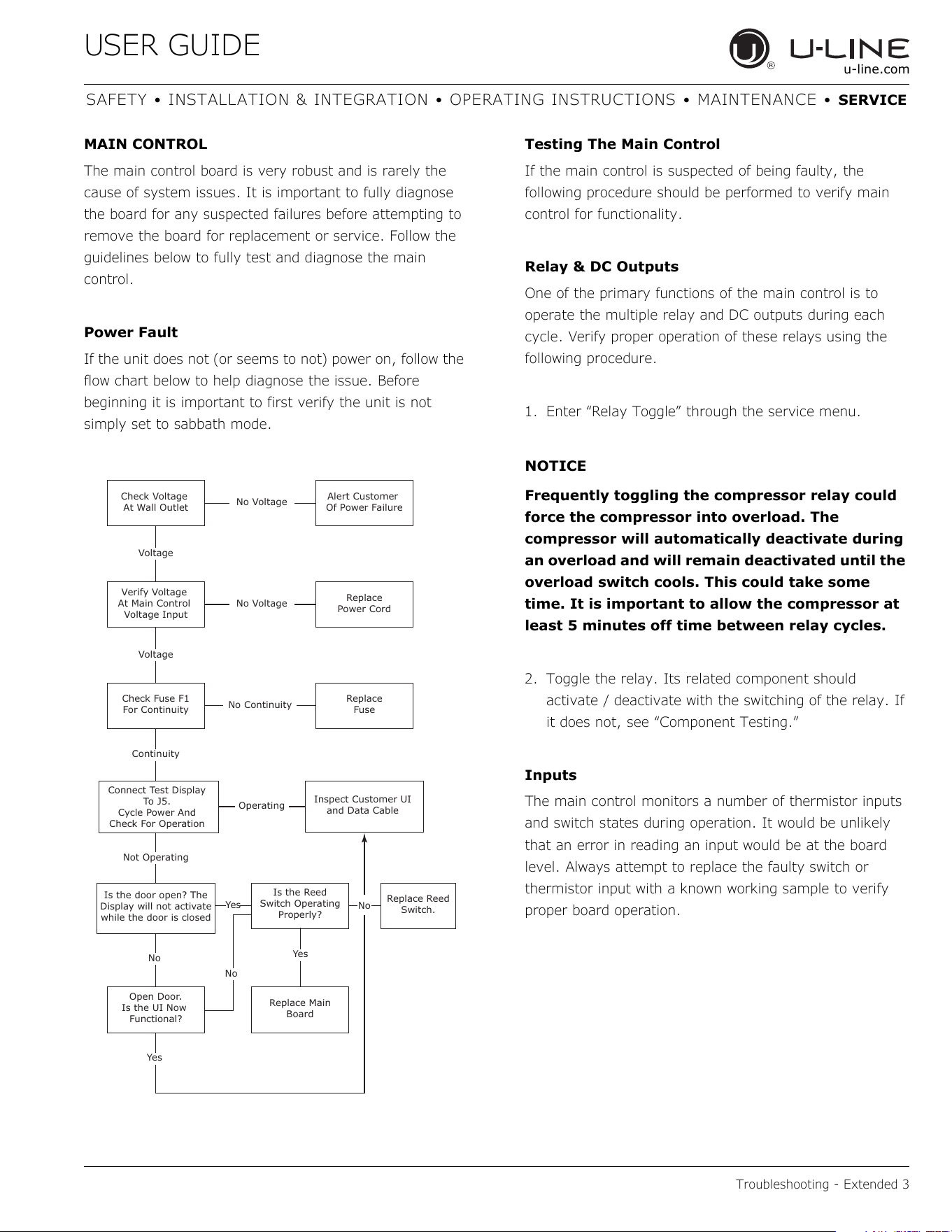
USER GUIDE
Troubleshooting - Extended 3
u-line.com
SAFETY • INSTALLATION & INTEGRATION • OPERATING INSTRUCTIONS • MAINTENANCE • SERVICE
MAIN CONTROL
The main control board is very robust and is rarely the
cause of system issues. It is important to fully diagnose
the board for any suspected failures before attempting to
remove the board for replacement or service. Follow the
guidelines below to fully test and diagnose the main
control.
Power Fault
If the unit does not (or seems to not) power on, follow the
flow chart below to help diagnose the issue. Before
beginning it is important to first verify the unit is not
simply set to sabbath mode.
Testing The Main Control
If the main control is suspected of being faulty, the
following procedure should be performed to verify main
control for functionality.
Relay & DC Outputs
One of the primary functions of the main control is to
operate the multiple relay and DC outputs during each
cycle. Verify proper operation of these relays using the
following procedure.
1. Enter “Relay Toggle” through the service menu.
NOTICE
Frequently toggling the compressor relay could
force the compressor into overload. The
compressor will automatically deactivate during
an overload and will remain deactivated until the
overload switch cools. This could take some
time. It is important to allow the compressor at
least 5 minutes off time between relay cycles.
2. Toggle the relay. Its related component should
activate / deactivate with the switching of the relay. If
it does not, see “Component Testing.”
Inputs
The main control monitors a number of thermistor inputs
and switch states during operation. It would be unlikely
that an error in reading an input would be at the board
level. Always attempt to replace the faulty switch or
thermistor input with a known working sample to verify
proper board operation.
Check Voltage
At Wall Outlet
Verify Voltage
At Main Control
Voltage Input
Check Fuse F1
For Continuity
Open Door.
Is the UI Now
Functional?
Replace Main
Board
Replace Reed
Switch.
Replace
Fuse
Replace
Power Cord
Alert Customer
Of Power Failure
Is the Reed
Switch Operating
Properly?
Is the door open? The
Display will not activate
while the door is closed
Inspect Customer UI
and Data Cable
Connect Test Display
To J5.
Cycle Power And
Check For Operation
No Voltage
No Voltage
Voltage
Continuity
Operating
Not Operating
No Continuity
No
No
No
Yes
Yes
Yes
Voltage
49
USER GUIDE
Troubleshooting - Extended 4
u-line.com
SAFETY • INSTALLATION & INTEGRATION • OPERATING INSTRUCTIONS • MAINTENANCE • SERVICE
Other Suspected Main Control Faults
If other components have been ruled out as being faulty
but the unit continues to have operating issues, it is most
likely due to a configuration error. Configuration errors
can be cleared by restoring the unit to its factory default
setting. Factory defaults may be restored through the
service menu.
CAUTION
!
Precautions must be taken while working with
live electrical equipment. Be sure to follow
proper safety procedures while performing tests
on live systems.
CONVECTION COOLING
All 3000 series units are equipped with an advanced
convection cooling system. Convection cooling stabilizes
cabinet temperature, cools product faster and increases
energy efficiency.
Evaporator Fan
The evaporator fan is responsible for circulating warm air
from the refrigeration zone, past the evaporator and back
into the refrigerated zone.
The evaporator fan is factory set to have a 1 minute delay
at the beginning of a cooling cycle. This delay gives the
evaporator time to cool properly before warm air is passed
over it. The fan will continue to run for an additional 2
minutes at the end of a cooling cycle. Fan delay times can
be modified through the service menu.
Evaporator fan operation is also determined by door
switch state. If the door switch circuit opens the fan will
stop. When the door switch circuit is closed the fan will
either continue running with the cooling cycle, or if not
currently cooling, the fan will run for 1 minute to circulate
air and clear any condensation that may have appeared
on glass doors and shelves.
NOTE: If the unit is set to sabbath mode the evaporator
fan will no longer respond to the state of the door switch.
In order to operate efficiently the evaporator fan blade
and vents should be unobstructed and free of any dust
buildup.
50
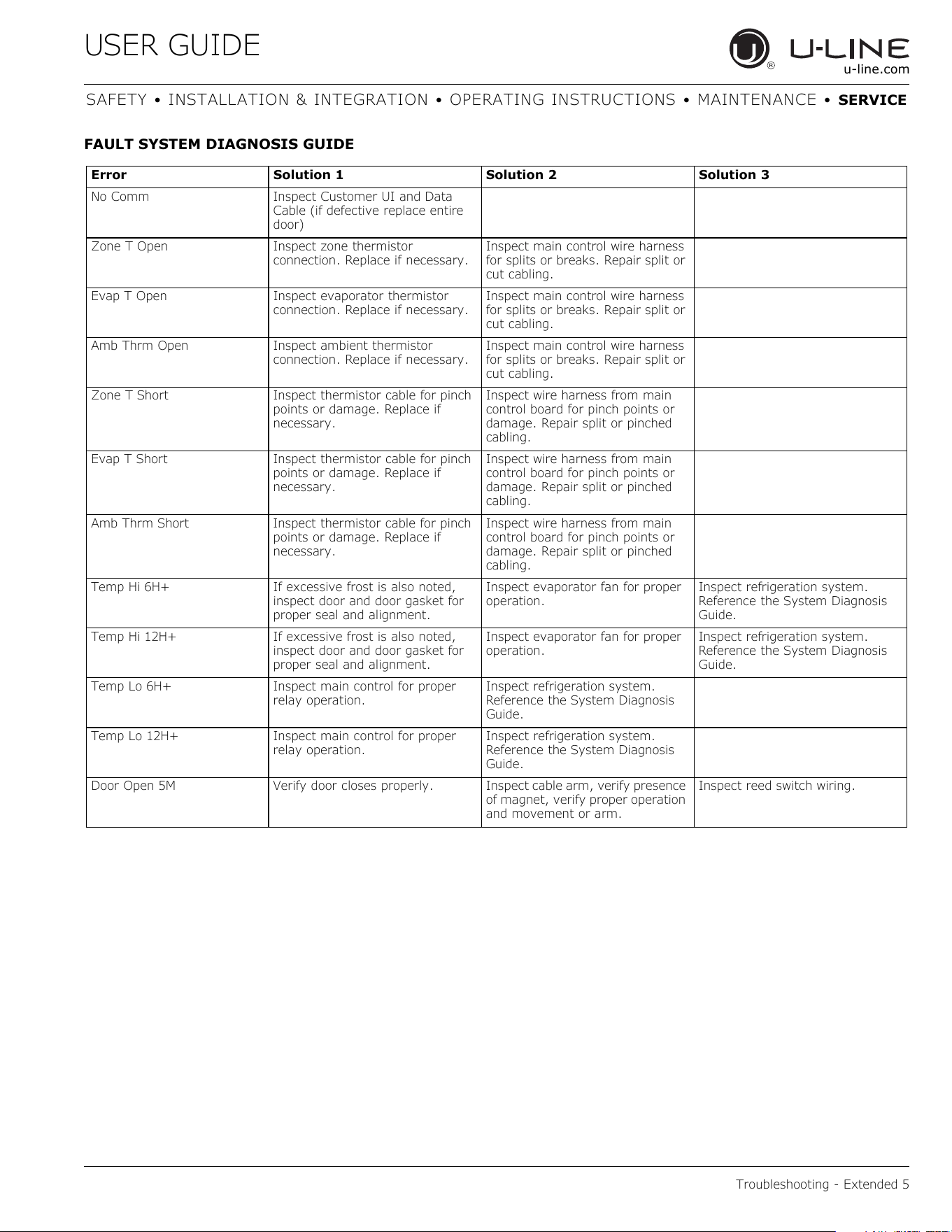
USER GUIDE
Troubleshooting - Extended 5
u-line.com
SAFETY • INSTALLATION & INTEGRATION • OPERATING INSTRUCTIONS • MAINTENANCE • SERVICE
FAULT SYSTEM DIAGNOSIS GUIDE
Error Solution 1 Solution 2 Solution 3
No Comm Inspect Customer UI and Data
Cable (if defective replace entire
door)
Zone T Open Inspect zone thermistor
connection. Replace if necessary.
Inspect main control wire harness
for splits or breaks. Repair split or
cut cabling.
Evap T Open Inspect evaporator thermistor
connection. Replace if necessary.
Inspect main control wire harness
for splits or breaks. Repair split or
cut cabling.
Amb Thrm Open Inspect ambient thermistor
connection. Replace if necessary.
Inspect main control wire harness
for splits or breaks. Repair split or
cut cabling.
Zone T Short Inspect thermistor cable for pinch
points or damage. Replace if
necessary.
Inspect wire harness from main
control board for pinch points or
damage. Repair split or pinched
cabling.
Evap T Short Inspect thermistor cable for pinch
points or damage. Replace if
necessary.
Inspect wire harness from main
control board for pinch points or
damage. Repair split or pinched
cabling.
Amb Thrm Short Inspect thermistor cable for pinch
points or damage. Replace if
necessary.
Inspect wire harness from main
control board for pinch points or
damage. Repair split or pinched
cabling.
Temp Hi 6H+ If excessive frost is also noted,
inspect door and door gasket for
proper seal and alignment.
Inspect evaporator fan for proper
operation.
Inspect refrigeration system.
Reference the System Diagnosis
Guide.
Temp Hi 12H+ If excessive frost is also noted,
inspect door and door gasket for
proper seal and alignment.
Inspect evaporator fan for proper
operation.
Inspect refrigeration system.
Reference the System Diagnosis
Guide.
Temp Lo 6H+ Inspect main control for proper
relay operation.
Inspect refrigeration system.
Reference the System Diagnosis
Guide.
Temp Lo 12H+ Inspect main control for proper
relay operation.
Inspect refrigeration system.
Reference the System Diagnosis
Guide.
Door Open 5M Verify door closes properly. Inspect cable arm, verify presence
of magnet, verify proper operation
and movement or arm.
Inspect reed switch wiring.
51
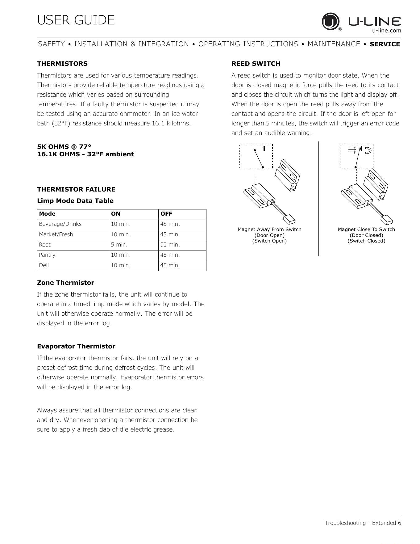
USER GUIDE
Troubleshooting - Extended 6
u-line.com
SAFETY • INSTALLATION & INTEGRATION • OPERATING INSTRUCTIONS • MAINTENANCE • SERVICE
THERMISTORS
Thermistors are used for various temperature readings.
Thermistors provide reliable temperature readings using a
resistance which varies based on surrounding
temperatures. If a faulty thermistor is suspected it may
be tested using an accurate ohmmeter. In an ice water
bath (32°F) resistance should measure 16.1 kilohms.
5K OHMS @ 77°
16.1K OHMS - 32°F ambient
THERMISTOR FAILURE
Limp Mode Data Table
Zone Thermistor
If the zone thermistor fails, the unit will continue to
operate in a timed limp mode which varies by model. The
unit will otherwise operate normally. The error will be
displayed in the error log.
Evaporator Thermistor
If the evaporator thermistor fails, the unit will rely on a
preset defrost time during defrost cycles. The unit will
otherwise operate normally. Evaporator thermistor errors
will be displayed in the error log.
Always assure that all thermistor connections are clean
and dry. Whenever opening a thermistor connection be
sure to apply a fresh dab of die electric grease.
REED SWITCH
A reed switch is used to monitor door state. When the
door is closed magnetic force pulls the reed to its contact
and closes the circuit which turns the light and display off.
When the door is open the reed pulls away from the
contact and opens the circuit. If the door is left open for
longer than 5 minutes, the switch will trigger an error code
and set an audible warning.
Mode ON OFF
Beverage/Drinks 10 min. 45 min.
Market/Fresh 10 min. 45 min.
Root 5 min. 90 min.
Pantry 10 min. 45 min.
Deli 10 min. 45 min.
Magnet Close To Switch
(Door Closed)
(Switch Closed)
Magnet Away From Switch
(Door Open)
(Switch Open)
52
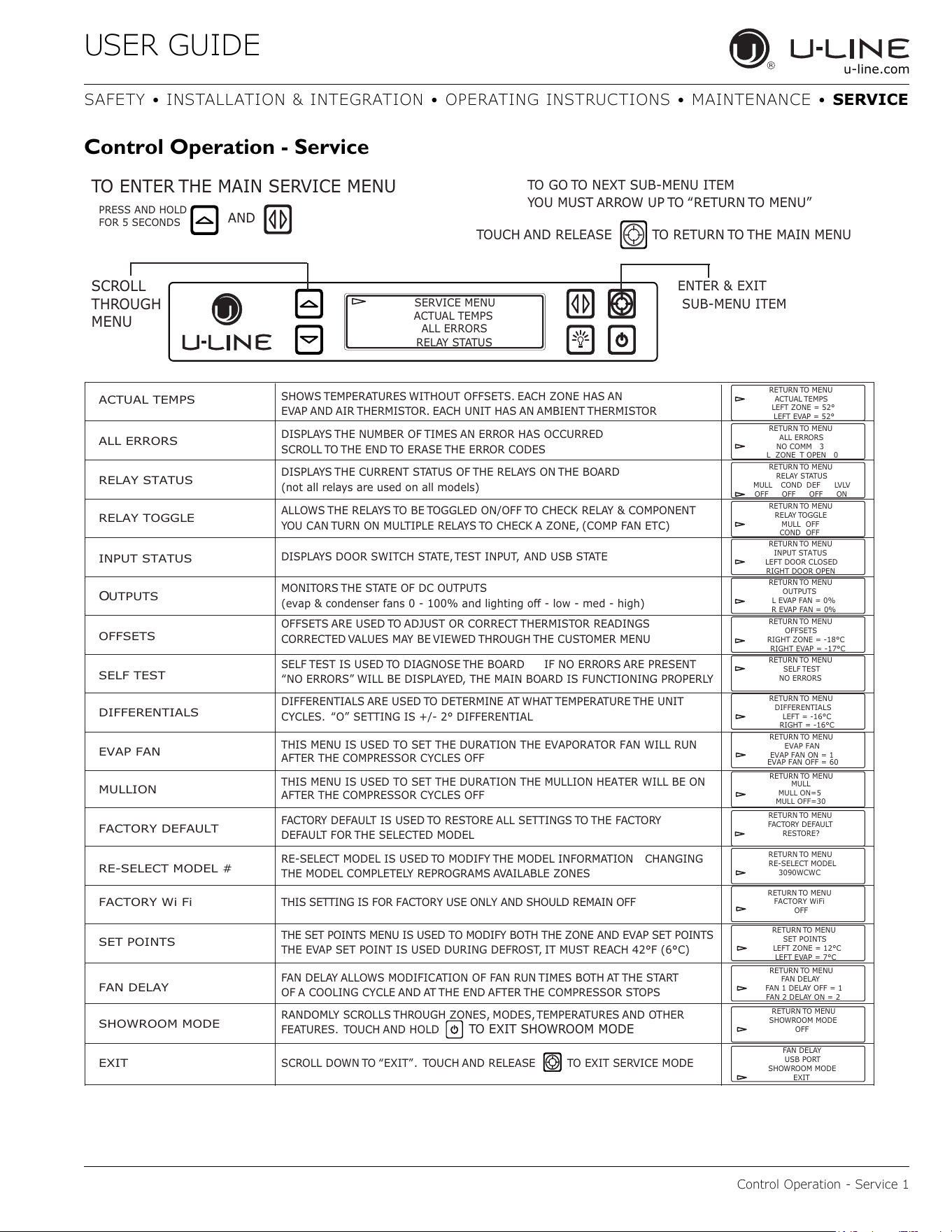
USER GUIDE
Control Operation - Service 1
u-line.com
SAFETY • INSTALLATION & INTEGRATION • OPERATING INSTRUCTIONS • MAINTENANCE • SERVICE
Control Operation - Service
ACTUAL TEMPS
ALL ERRORS
RELAY STATUS
RELAY TOGGLE
INPUT STATUS
O
UTPUTS
OFFSETS
SELF TEST
SET POINTS
MULLION
RE-SELECT MODEL #
FACTORY Wi Fi
FACTORY DEFAULT
TO ENTER THE MAIN SERVICE MENU
PRESS AND HOLD
FOR 5 SECONDS
AND
SERVICE MENU
ACTUAL TEMPS
RELAY STATUS
ALL ERRORS
ENTER & EXIT
SUB-MENU ITEM
SCROLL
THROUGH
MENU
SHOWS TEMPERATURES WITHOUT OFFSETS. EACH ZONE HAS AN
EVAP AND AIR THERMISTOR. EACH UNIT HAS AN AMBIENT THERMISTOR
RETURN TO MENU
ACTUAL TEMPS
LEFT ZONE = 52°
LEFT EVAP = 52°
RETURN TO MENU
ALL ERRORS
NO COMM 3
L ZONE T OPEN 0
RETURN TO MENU
RELAY STATUS
MULL COND DEF LVLV
OFF OFF OFF ON
RETURN TO MENU
RELAY TOGGLE
MULL OFF
COND OFF
RETURN TO MENU
INPUT STATUS
LEFT DOOR CLOSED
RIGHT DOOR OPEN
RETURN TO MENU
OUTPUTS
L EVAP FAN = 0%
R EVAP FAN = 0%
RETURN TO MENU
OFFSETS
RIGHT ZONE = -18°C
RIGHT EVAP = -17°C
RETURN TO MENU
SELF TEST
NO ERRORS
RETURN TO MENU
SET POINTS
LEFT ZONE = 12°C
LEFT EVAP = 7°C
RETURN TO MENU
FACTORY DEFAULT
RESTORE?
RETURN TO MENU
RETURN TO MENU
RE-SELECT MODEL
3090WCWC
DISPLAYS THE NUMBER OF TIMES AN ERROR HAS OCCURRED
SCROLL TO THE END TO ERASE THE ERROR CODES
DISPLAYS THE CURRENT STATUS OF THE RELAYS ON THE BOARD
(not all relays are used on all models)
ALLOWS THE RELAYS TO BE TOGGLED ON/OFF TO CHECK RELAY & COMPONENT
YOU CAN TURN ON MULTIPLE RELAYS TO CHECK A ZONE, (COMP FAN ETC)
DISPLAYS DOOR SWITCH STATE, TEST INPUT, AND USB STATE
MONITORS THE STATE OF DC OUTPUTS
(evaSFRQGHQVHUIDQVDQGOLJKWLQJRɞOow - med - high)
OFFSETS ARE USED TO ADJUST OR CORRECT THERMISTOR READINGS
CORRECTED VALUES MAY BE VIEWED THROUGH THE CUSTOMER MENU
SELF TEST IS USED TO DIAGNOSE THE BOARD IF NO ERRORS ARE PRESENT
“NO ERRORS” WILL BE DISPLAYED, THE MAIN BOARD IS FUNCTIONING PROPERLY
THE SET POINTS MENU IS USED TO MODIFY BOTH THE ZONE AND EVAP SET POINTS
THIS SETTING IS FOR FACTORY USE ONLY AND SHOULD REMAIN OFF
THE EVAP SET POINT IS USED DURING DEFROST, IT MUST REACH 42°F (6°C)
FACTORY DEFAULT IS USED TO RESTORE ALL SETTINGS TO THE FACTORY
DEFAULT FOR THE SELECTED MODEL
FAN DELAY
SHOWROOM MODE
EXIT
RETURN TO MENU
FAN DELAY
FAN 1 DELAY OFF = 1
FAN 2 DELAY ON = 2
RETURN TO MENU
SHOWROOM MODE
OFF
FACTORY WiFi
OFF
FAN DELAY
USB PORT
SHOWROOM MODE
EXIT
RANDOMLY SCROLLS THROUGH ZONES, MODES, TEMPERATURES AND OTHER
FEATURES. TOUCH AND HOLD
TO EXIT SHOWROOM MODE
SCROLL DOWN TO “EXIT”. TOUCH AND RELEASE TO EXIT SERVICE MODE
FAN DELAY ALLOWS MODIFICATION OF FAN RUN TIMES BOTH AT THE START
OF A COOLING CYCLE AND AT THE END AFTER THE COMPRESSOR STOPS
RE-SELECT MODEL IS USED TO MODIFY THE MODEL INFORMATION CHANGING
THE MODEL COMPLETELY REPROGRAMS AVAILABLE ZONES
TO GO TO NEXT SUB-MENU ITEM
YOU MUST ARROW UP TO “RETURN TO MENU”
TOUCH AND RELEASE
TO RETURN TO THE MAIN MENU
EVAP FAN
RETURN TO MENU
EVAP FAN
EVAP FAN ON = 1
EVAP FAN OFF = 60
THIS MENU IS USED TO SET THE DURATION THE EVAPORATOR FAN WILL RUN
AFTER THE COMPRESSOR CYCLES OFF
THIS MENU IS USED TO SET THE DURATION THE MULLION HEATER WILL BE ON
AFTER THE COMPRESSOR CYCLES OFF
RETURN TO MENU
MULL
MULL ON=5
MULL OFF=30
DIFFERENTIALS
RETURN TO MENU
DIFFERENTIALS
LEFT = -16°C
RIGHT = -16°C
DIFFERENTIALS ARE USED TO DETERMINE AT WHAT TEMPERATURE THE UNIT
CYCLES. “O” SETTING IS +/- 2° DIFFERENTIAL
53
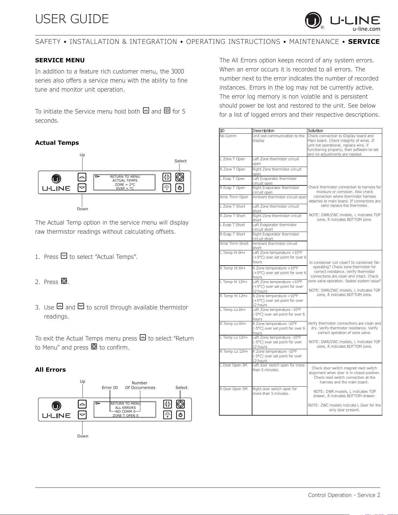
USER GUIDE
Control Operation - Service 2
u-line.com
SAFETY • INSTALLATION & INTEGRATION • OPERATING INSTRUCTIONS • MAINTENANCE • SERVICE
SERVICE MENU
In addition to a feature rich customer menu, the 3000
series also offers a service menu with the ability to fine
tune and monitor unit operation.
To initiate the Service menu hold both and for 5
seconds.
Actual Temps
The Actual Temp option in the service menu will display
raw thermistor readings without calculating offsets.
1. Press to select “Actual Temps”.
2. Press .
3. Use and to scroll through available thermistor
readings.
To exit the Actual Temps menu press to select “Return
to Menu” and press to confirm.
All Errors
The All Errors option keeps record of any system errors.
When an error occurs it is recorded to all errors. The
number next to the error indicates the number of recorded
instances. Errors in the log may not be currently active.
The error log memory is non volatile and is persistent
should power be lost and restored to the unit. See below
for a list of logged errors and their respective descriptions.
Up
Select
Down
RETURN TO MENU
ACTUAL TEMPS
ZONE = 2°C
EVAP = °C
Up
Error ID
Number
Of Occurrences Select
Down
RETURN TO MENU
ALL ERRORS
NO COMM 0
ZONE T OPEN 0
ID Description Soluti on
No Comm
Unit lost communication to the
display
Check connection to Display board and
Main board. Check integrity of wires. If
unit not operational, replace wire, if
functioning properly, then software re-set
and no ad
j
ustments are needed.
L Zone T Open
Left Zone thermistor circuit
open
R Zone T Open
Right Zone thermistor circuit
o
p
en
L Evap T Open
Left Evaporator thermistor
circuit o
p
en
R Evap T Open
Right Evaporator thermistor
circuit o
p
en
Amb Thrm Open Ambient thermistor circuit open
L Zone T Short
Left Zone thermistor circuit
short
R Zone T Short
Right Zone thermistor circuit
short
L Evap T Short
Left Evaporator thermistor
circuit short
R Evap T Short
Right Evaporator thermistor
circuit short
Amb Thrm Short Ambient thermistor circuit
short
L Temp Hi 6H+
Left Zone temperature +10°F
(+5°C) over set point for over 6
hours
R Temp Hi 6H+
R Zone temperature +10°F
(+5°C) over set point for over 6
hours
L Temp Hi 12H+
Left Zone temperature +10°F
(+5°C) over set point for over
12 hours
R Temp Hi 12H+
R Zone temperature +10°F
(+5°C) over set point for over
12 hours
L Temp Lo 6H+
Left Zone temperature -10°F
(-5°C) over set point for over 6
hours
R Temp Lo 6H+
R Zone temperature -10°F
(-5°C) over set point for over 6
hours
L Temp Lo 12H+
Left Zone temperature -10°F
(-5°C) over set point for over
12 hours
R Temp Lo 12H+
R Zone temperature -10°F
(-5°C) over set point for over
12 hours
L Door Open 5M
Left door switch open for more
than 5 minutes.
R Door Open 5M
Right door switch open for
more than 5 minutes.
Check thermistor connection to harness for
moisture or corrosion. Also check
connection where thermistor harness
attaches to main board. If connections are
valid replace the thermistor.
NOTE: DWR/ZWC models, L indicates TOP
zone, R indicates BOTTOM zone.
Is condenser coil clean? Is condenser fan
operating? Check zone thermistor for
correct resistance. Verify thermistor
connections are clean and intact. Check
zone valve operation. Sealed system issue?
NOTE: DWR/ZWC models, L indicates TOP
zone, R indicates BOTTOM zone.
Verify thermistor connections are clean and
dry. Verify thermistor resistance. Verify
correct operation of zone valve.
NOTE: DWR/ZWC models, L indicates TOP
zone, R indicates BOTTOM zone.
Check door switch magnet reed switch
alignment when door is in closed position.
Check reed switch connection at the
harness and the main board.
NOTE: DWR models, L indicates TOP
drawer, R indicates BOTTOM drawer.
NOTE: ZWC models indicate L Door for the
only door present.
54
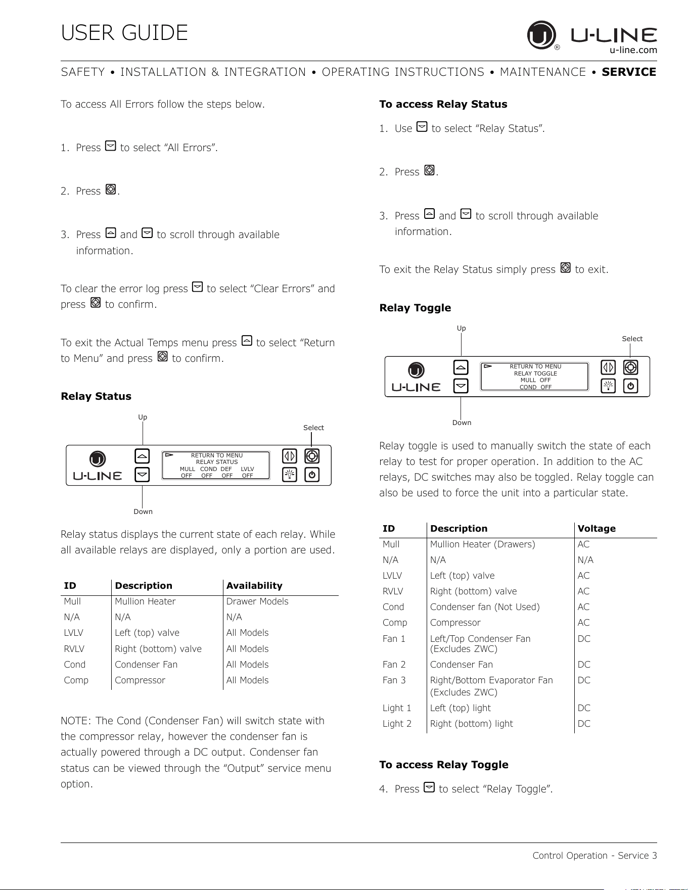
USER GUIDE
Control Operation - Service 3
u-line.com
SAFETY • INSTALLATION & INTEGRATION • OPERATING INSTRUCTIONS • MAINTENANCE • SERVICE
To access All Errors follow the steps below.
1. Press to select “All Errors”.
2. Press .
3. Press and to scroll through available
information.
To clear the error log press to select “Clear Errors” and
press to confirm.
To exit the Actual Temps menu press to select “Return
to Menu” and press to confirm.
Relay Status
Relay status displays the current state of each relay. While
all available relays are displayed, only a portion are used.
NOTE: The Cond (Condenser Fan) will switch state with
the compressor relay, however the condenser fan is
actually powered through a DC output. Condenser fan
status can be viewed through the “Output” service menu
option.
To access Relay Status
1. Use to select “Relay Status”.
2. Press .
3. Press and to scroll through available
information.
To exit the Relay Status simply press to exit.
Relay Toggle
Relay toggle is used to manually switch the state of each
relay to test for proper operation. In addition to the AC
relays, DC switches may also be toggled. Relay toggle can
also be used to force the unit into a particular state.
To access Relay Toggle
4. Press to select “Relay Toggle”.
ID Description Availability
Mull Mullion Heater Drawer Models
N/A N/A N/A
LVLV Left (top) valve All Models
RVLV Right (bottom) valve All Models
Cond Condenser Fan All Models
Comp Compressor All Models
Up
Select
Down
RETURN TO MENU
RELAY STATUS
MULL COND DEF LVLV
OFF OFF OFF OFF
ID Description Voltage
Mull Mullion Heater (Drawers) AC
N/A N/A N/A
LVLV Left (top) valve AC
RVLV Right (bottom) valve AC
Cond Condenser fan (Not Used) AC
Comp Compressor AC
Fan 1 Left/Top Condenser Fan
(Excludes ZWC)
DC
Fan 2 Condenser Fan DC
Fan 3 Right/Bottom Evaporator Fan
(Excludes ZWC)
DC
Light 1 Left (top) light DC
Light 2 Right (bottom) light DC
Up
Select
Down
RETURN TO MENU
RELAY TOGGLE
MULL OFF
COND OFF
55
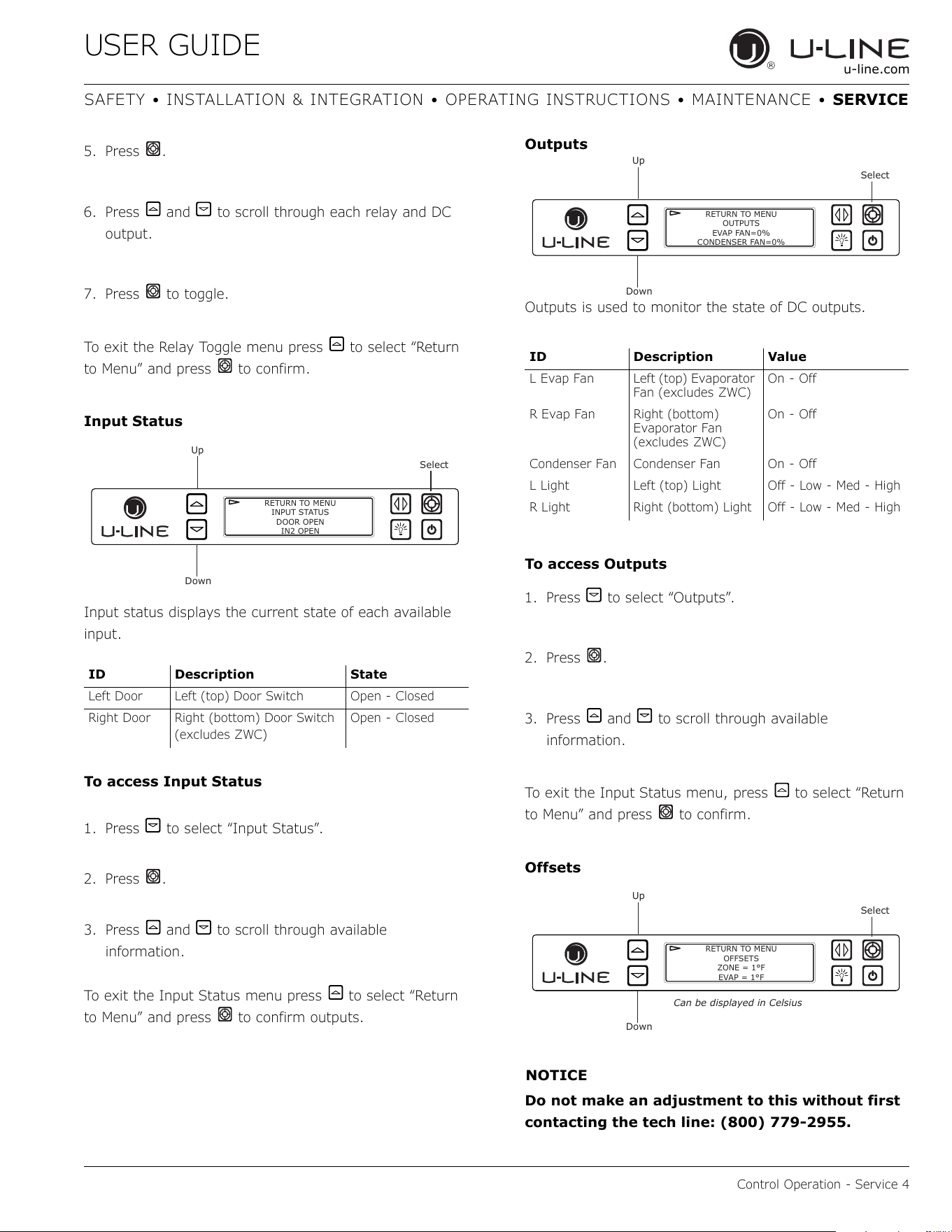
USER GUIDE
Control Operation - Service 4
u-line.com
SAFETY • INSTALLATION & INTEGRATION • OPERATING INSTRUCTIONS • MAINTENANCE • SERVICE
5. Press .
6. Press and to scroll through each relay and DC
output.
7. Press to toggle.
To exit the Relay Toggle menu press to select “Return
to Menu” and press to confirm.
Input Status
Input status displays the current state of each available
input.
To access Input Status
1. Press to select “Input Status”.
2. Press .
3. Press and to scroll through available
information.
To exit the Input Status menu press to select “Return
to Menu” and press to confirm outputs.
Outputs
Outputs is used to monitor the state of DC outputs.
To access Outputs
1. Press to select “Outputs”.
2. Press .
3. Press and to scroll through available
information.
To exit the Input Status menu, press to select “Return
to Menu” and press to confirm.
Offsets
NOTICE
Do not make an adjustment to this without first
contacting the tech line: (800) 779-2955.
ID Description State
Left Door Left (top) Door Switch Open - Closed
Right Door Right (bottom) Door Switch
(excludes ZWC)
Open - Closed
Up
Select
Down
RETURN TO MENU
INPUT STATUS
DOOR OPEN
IN2 OPEN
ID Description Value
L Evap Fan Left (top) Evaporator
Fan (excludes ZWC)
On - Off
R Evap Fan Right (bottom)
Evaporator Fan
(excludes ZWC)
On - Off
Condenser Fan Condenser Fan On - Off
L Light Left (top) Light Off - Low - Med - High
R Light Right (bottom) Light Off - Low - Med - High
Up
Select
Down
RETURN TO MENU
OUTPUTS
EVAP FAN=0%
CONDENSER FAN=0%
Up
Select
Down
RETURN TO MENU
OFFSETS
ZONE = 1°F
EVAP = 1°F
Can be displayed in Celsius
56
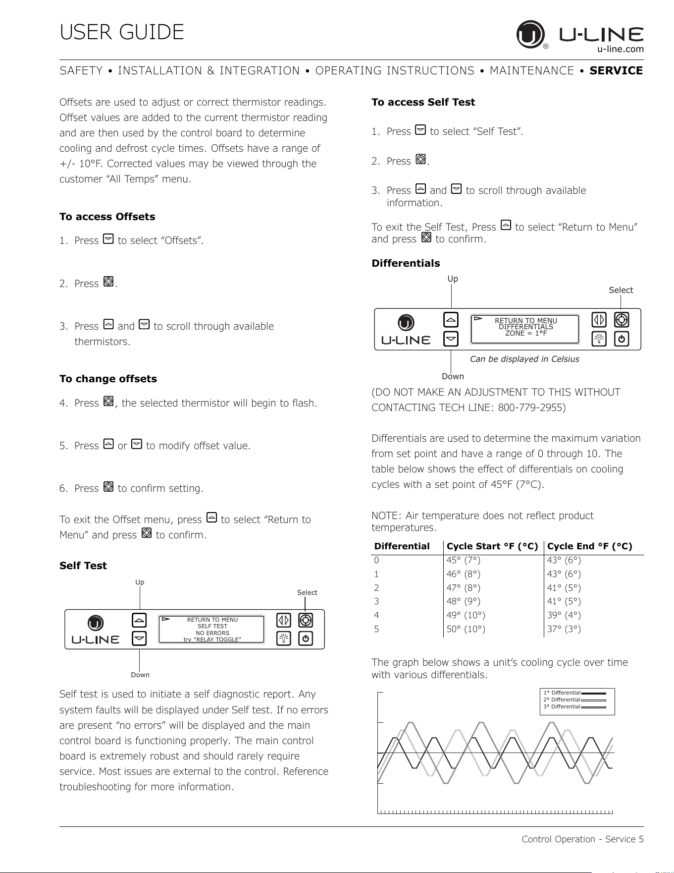
USER GUIDE
Control Operation - Service 5
u-line.com
SAFETY • INSTALLATION & INTEGRATION • OPERATING INSTRUCTIONS • MAINTENANCE • SERVICE
Offsets are used to adjust or correct thermistor readings.
Offset values are added to the current thermistor reading
and are then used by the control board to determine
cooling and defrost cycle times. Offsets have a range of
+/- 10°F. Corrected values may be viewed through the
customer “All Temps” menu.
To access Offsets
1. Press to select “Offsets”.
2. Press .
3. Press and to scroll through available
thermistors.
To change offsets
4. Press , the selected thermistor will begin to flash.
5. Press or to modify offset value.
6. Press to confirm setting.
To exit the Offset menu, press to select “Return to
Menu” and press to confirm.
Self Test
Self test is used to initiate a self diagnostic report. Any
system faults will be displayed under Self test. If no errors
are present “no errors” will be displayed and the main
control board is functioning properly. The main control
board is extremely robust and should rarely require
service. Most issues are external to the control. Reference
troubleshooting for more information.
To access Self Test
1. Press to select “Self Test”.
2. Press .
3. Press and to scroll through available
information.
To exit the Self Test, Press to select “Return to Menu”
and press to confirm.
Differentials
(DO NOT MAKE AN ADJUSTMENT TO THIS WITHOUT
CONTACTING TECH LINE: 800-779-2955)
Differentials are used to determine the maximum variation
from set point and have a range of 0 through 10. The
table below shows the effect of differentials on cooling
cycles with a set point of 45°F (7°C).
NOTE: Air temperature does not reflect product
temperatures.
The graph below shows a unit’s cooling cycle over time
with various differentials.
Up
Select
Down
RETURN TO MENU
SELF TEST
NO ERRORS
try “RELAY TOGGLE”
Differential Cycle Start °F (°C) Cycle End °F (°C)
0 45° (7°) 43° (6°)
1 46° (8°) 43° (6°)
2 47° (8°) 41° (5°)
3 48° (9°) 41° (5°)
4 49° (10°) 39° (4°)
5 50° (10°) 37° (3°)
Up
Select
Down
RETURN TO MENU
DIFFERENTIALS
ZONE = 1°F
Can be displayed in Celsius
p'LɞHUHQWLDO
p'LɞHUHQWLDO
p'LɞHUHQWLDO
57
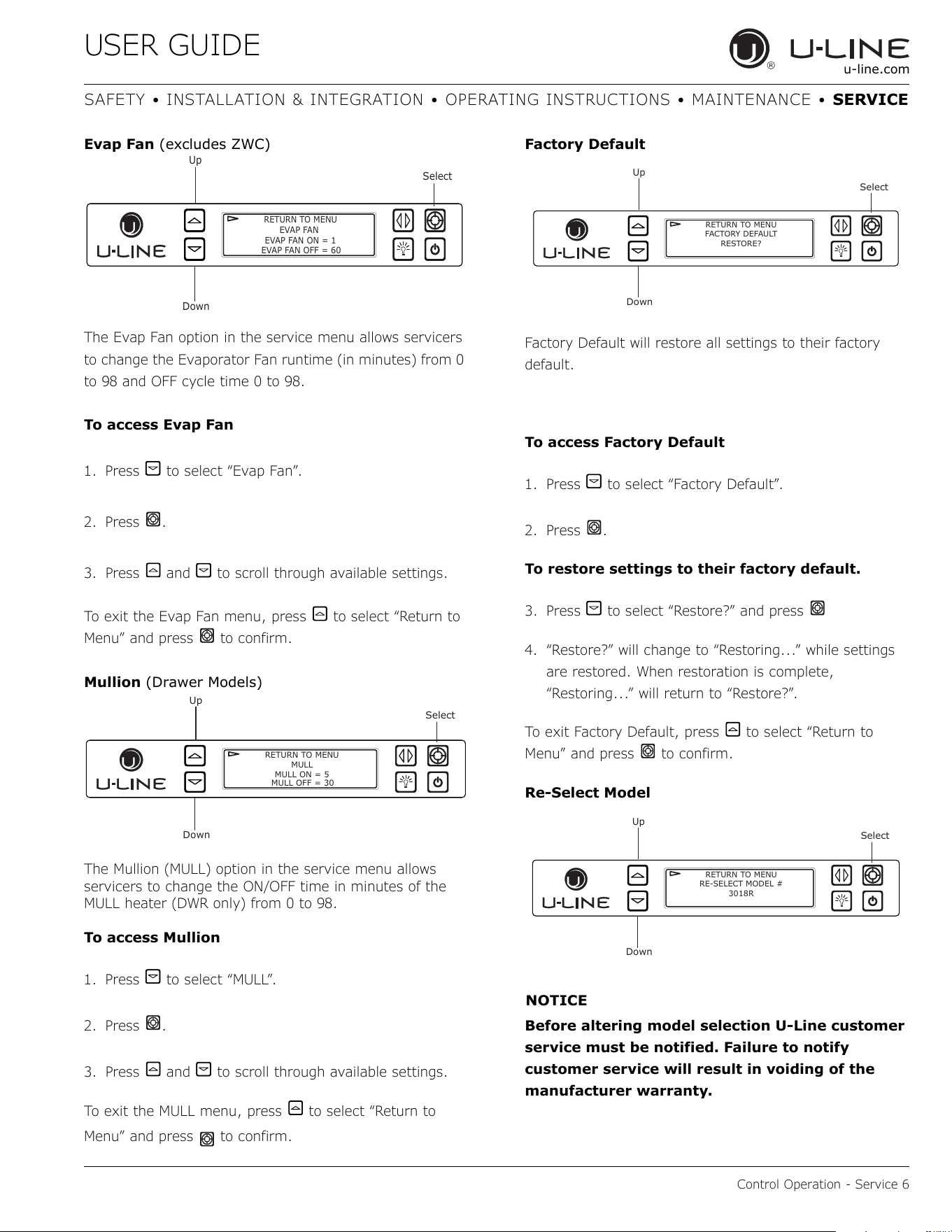
USER GUIDE
Control Operation - Service 6
u-line.com
SAFETY • INSTALLATION & INTEGRATION • OPERATING INSTRUCTIONS • MAINTENANCE • SERVICE
Evap Fan (excludes ZWC)
The Evap Fan option in the service menu allows servicers
to change the Evaporator Fan runtime (in minutes) from 0
to 98 and OFF cycle time 0 to 98.
To access Evap Fan
1. Press to select “Evap Fan”.
2. Press .
3. Press and to scroll through available settings.
To exit the Evap Fan menu, press to select “Return to
Menu” and press to confirm.
Mullion (Drawer Models)
The Mullion (MULL) option in the service menu allows
servicers to change the ON/OFF time in minutes of the
MULL heater (DWR only) from 0 to 98.
To access Mullion
1. Press to select “MULL”.
2. Press .
3. Press and to scroll through available settings.
To exit the MULL menu, press to select “Return to
Menu” and press to confirm.
Factory Default
Factory Default will restore all settings to their factory
default.
To access Factory Default
1. Press to select “Factory Default”.
2. Press .
To restore settings to their factory default.
3. Press to select “Restore?” and press
4. “Restore?” will change to “Restoring...” while settings
are restored. When restoration is complete,
“Restoring...” will return to “Restore?”.
To exit Factory Default, press to select “Return to
Menu” and press to confirm.
Re-Select Model
NOTICE
Before altering model selection U-Line customer
service must be notified. Failure to notify
customer service will result in voiding of the
manufacturer warranty.
Up
Select
Down
RETURN TO MENU
EVAP FAN
EVAP FAN ON = 1
EVAP FAN OFF = 60
Up
Select
Down
RETURN TO MENU
MULL
MULL ON = 5
MULL OFF = 30
Up
Select
Down
RETURN TO MENU
FACTORY DEFAULT
RESTORE?
Up
Select
Down
RETURN TO MENU
RE-SELECT MODEL #
3018R
58
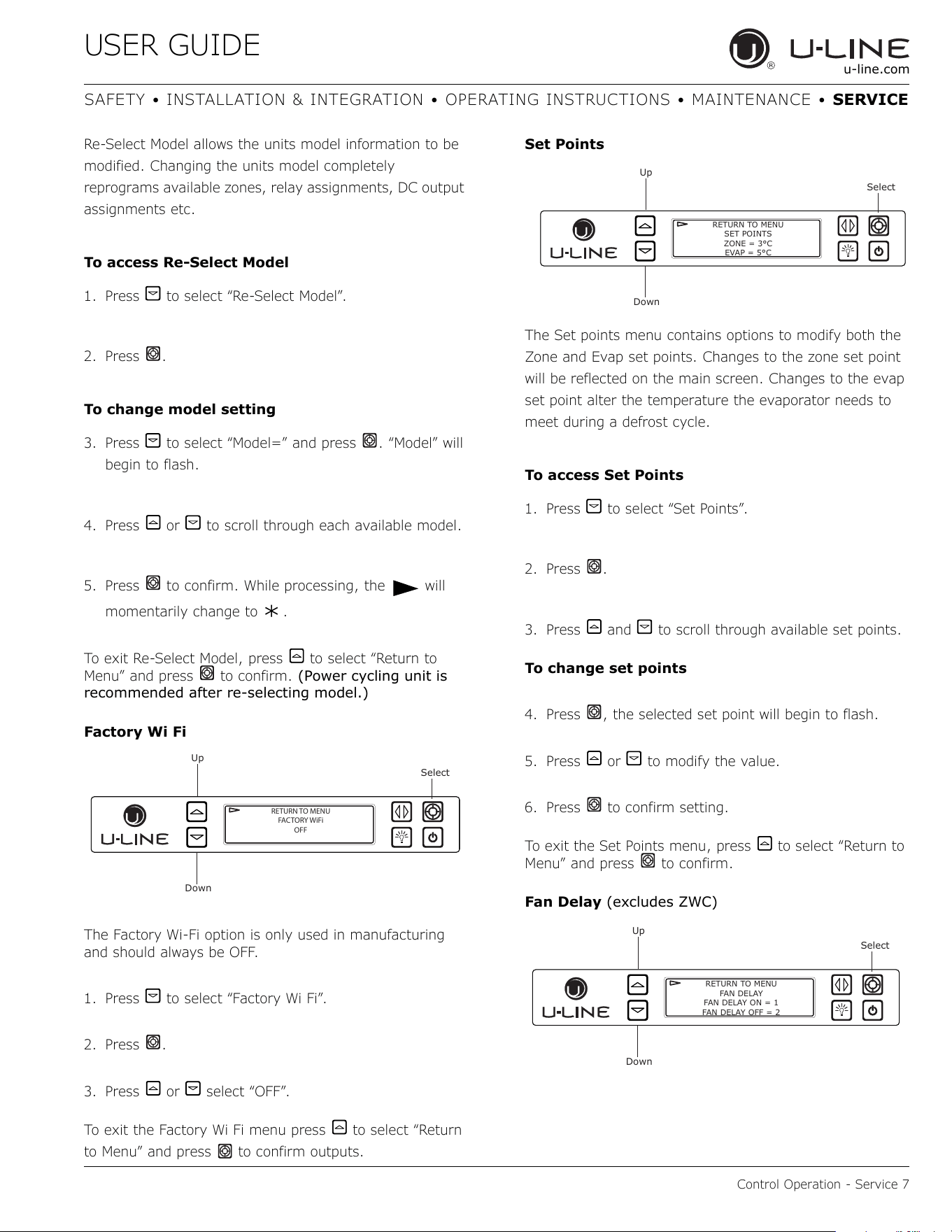
USER GUIDE
Control Operation - Service 7
u-line.com
SAFETY • INSTALLATION & INTEGRATION • OPERATING INSTRUCTIONS • MAINTENANCE • SERVICE
Re-Select Model allows the units model information to be
modified. Changing the units model completely
reprograms available zones, relay assignments, DC output
assignments etc.
To access Re-Select Model
1. Press to select “Re-Select Model”.
2. Press .
To change model setting
3. Press to select “Model=” and press . “Model” will
begin to flash.
4. Press or to scroll through each available model.
5. Press to confirm. While processing, the will
momentarily change to .
To exit Re-Select Model, press to select “Return to
Menu” and press to confirm. (Power cycling unit is
recommended after re-selecting model.)
Factory Wi Fi
The Factory Wi-Fi option is only used in manufacturing
and should always be OFF.
1. Press to select “Factory Wi Fi”.
2. Press .
3. Press or select “OFF”.
To exit the Factory Wi Fi menu press to select “Return
to Menu” and press to confirm outputs.
Set Points
The Set points menu contains options to modify both the
Zone and Evap set points. Changes to the zone set point
will be reflected on the main screen. Changes to the evap
set point alter the temperature the evaporator needs to
meet during a defrost cycle.
To access Set Points
1. Press to select “Set Points”.
2. Press .
3. Press and to scroll through available set points.
To change set points
4. Press , the selected set point will begin to flash.
5. Press or to modify the value.
6. Press to confirm setting.
To exit the Set Points menu, press to select “Return to
Menu” and press to confirm.
Fan Delay (excludes ZWC)
Up
Select
Down
RETURN TO MENU
FACTORY WiFi
OFF
Up
Select
Down
RETURN TO MENU
SET POINTS
ZONE = 3°C
EVAP = 5°C
Up
Select
Down
RETURN TO MENU
FAN DELAY
FAN DELAY ON = 1
FAN DELAY OFF = 2
*
59
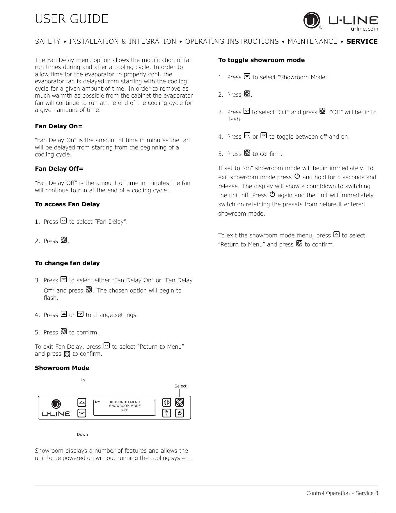
USER GUIDE
Control Operation - Service 8
u-line.com
SAFETY • INSTALLATION & INTEGRATION • OPERATING INSTRUCTIONS • MAINTENANCE • SERVICE
The Fan Delay menu option allows the modification of fan
run times during and after a cooling cycle. In order to
allow time for the evaporator to properly cool, the
evaporator fan is delayed from starting with the cooling
cycle for a given amount of time. In order to remove as
much warmth as possible from the cabinet the evaporator
fan will continue to run at the end of the cooling cycle for
a given amount of time.
Fan Delay On=
“Fan Delay On” is the amount of time in minutes the fan
will be delayed from starting from the beginning of a
cooling cycle.
Fan Delay Off=
“Fan Delay Off” is the amount of time in minutes the fan
will continue to run at the end of a cooling cycle.
To access Fan Delay
1. Press to select “Fan Delay”.
2. Press .
To change fan delay
3. Press to select either “Fan Delay On” or “Fan Delay
Off” and press . The chosen option will begin to
flash.
4. Press or to change settings.
5. Press to confirm.
To exit Fan Delay, press to select “Return to Menu”
and press to confirm.
Showroom Mode
Showroom displays a number of features and allows the
unit to be powered on without running the cooling system.
To toggle showroom mode
1. Press to select “Showroom Mode”.
2. Press .
3. Press to select “Off” and press . “Off” will begin to
flash.
4. Press or to toggle between off and on.
5. Press to confirm.
If set to “on” showroom mode will begin immediately. To
exit showroom mode press and hold for 5 seconds and
release. The display will show a countdown to switching
the unit off. Press again and the unit will immediately
switch on retaining the presets from before it entered
showroom mode.
To exit the showroom mode menu, press to select
“Return to Menu” and press to confirm.
Up
Select
Down
RETURN TO MENU
SHOWROOM MODE
OFF
60
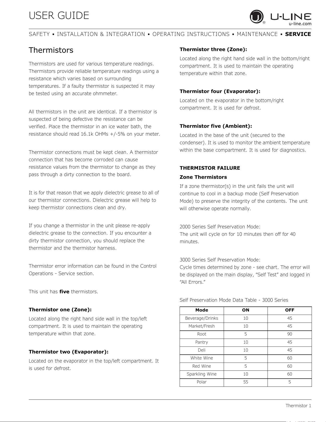
USER GUIDE
Thermistor 1
u-line.com
SAFETY • INSTALLATION & INTEGRATION • OPERATING INSTRUCTIONS • MAINTENANCE • SERVICE
Thermistors
Thermistors are used for various temperature readings.
Thermistors provide reliable temperature readings using a
resistance which varies based on surrounding
temperatures. If a faulty thermistor is suspected it may
be tested using an accurate ohmmeter.
All thermistors in the unit are identical. If a thermistor is
suspected of being defective the resistance can be
verified. Place the thermistor in an ice water bath, the
resistance should read 16.1k OHMs +/-5% on your meter.
Thermistor connections must be kept clean. A thermistor
connection that has become corroded can cause
resistance values from the thermistor to change as they
pass through a dirty connection to the board.
It is for that reason that we apply dielectric grease to all of
our thermistor connections. Dielectric grease will help to
keep thermistor connections clean and dry.
If you change a thermistor in the unit please re-apply
dielectric grease to the connection. If you encounter a
dirty thermistor connection, you should replace the
thermistor and the thermistor harness.
Thermistor error information can be found in the Control
Operations - Service section.
This unit has five thermistors.
Thermistor one (Zone):
Located along the right hand side wall in the top/left
compartment. It is used to maintain the operating
temperature within that zone.
Thermistor two (Evaporator):
Located on the evaporator in the top/left compartment. It
is used for defrost.
Thermistor three (Zone):
Located along the right hand side wall in the bottom/right
compartment. It is used to maintain the operating
temperature within that zone.
Thermistor four (Evaporator):
Located on the evaporator in the bottom/right
compartment. It is used for defrost.
Thermistor five (Ambient):
Located in the base of the unit (secured to the
condenser). It is used to monitor the ambient temperature
within the base compartment. It is used for diagnostics.
THERMISTOR FAILURE
Zone Thermistors
If a zone thermistor(s) in the unit fails the unit will
continue to cool in a backup mode (Self Preservation
Mode) to preserve the integrity of the contents. The unit
will otherwise operate normally.
2000 Series Self Preservation Mode:
The unit will cycle on for 10 minutes then off for 40
minutes.
3000 Series Self Preservation Mode:
Cycle times determined by zone - see chart. The error will
be displayed on the main display, “Self Test” and logged in
“All Errors.”
Self Preservation Mode Data Table - 3000 Series
Mode ON OFF
Beverage/Drinks 10 45
Market/Fresh 10 45
Root 5 90
Pantry 10 45
Deli 10 45
White Wine 5 60
Red Wine 5 60
Sparkling Wine 10 60
Polar 55 5
61
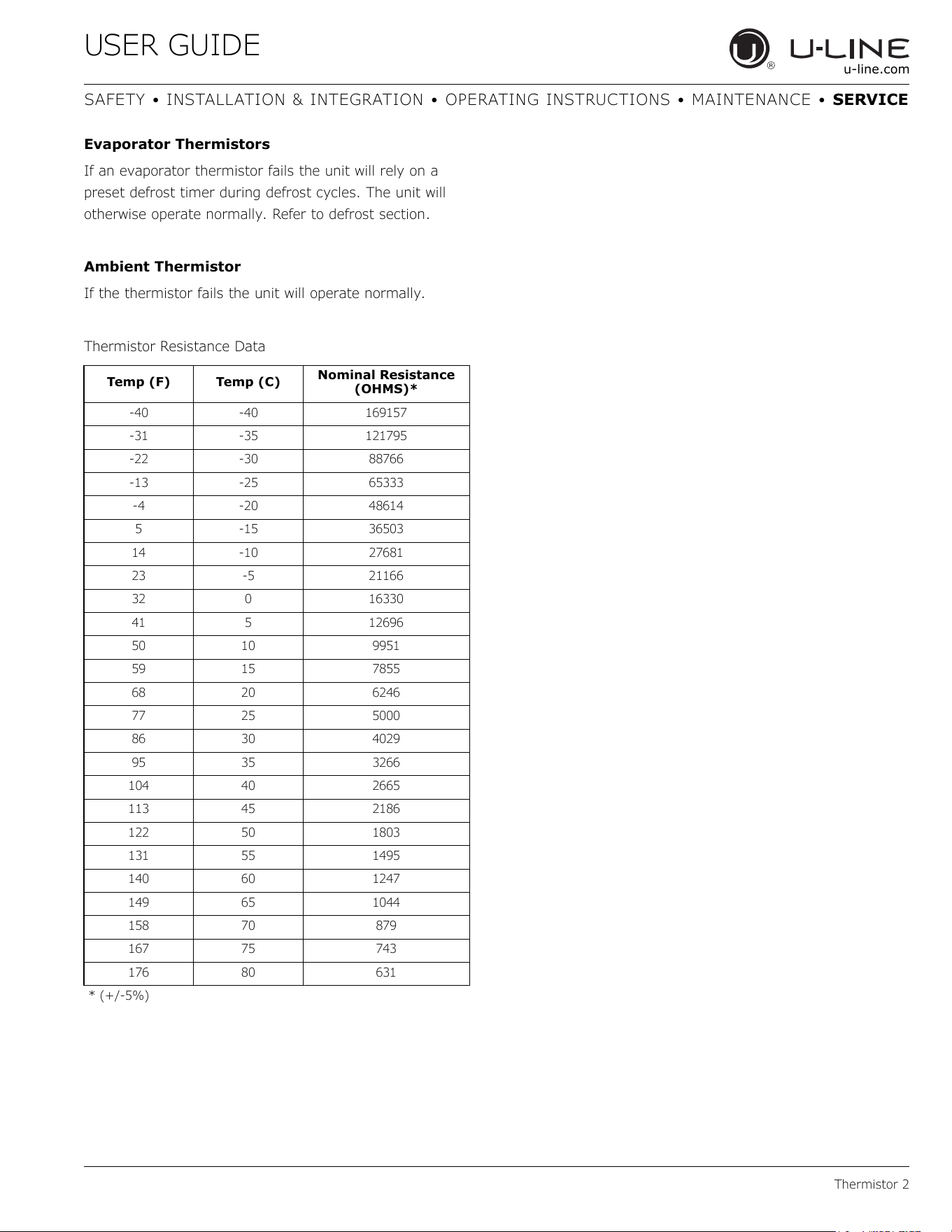
USER GUIDE
Thermistor 2
u-line.com
SAFETY • INSTALLATION & INTEGRATION • OPERATING INSTRUCTIONS • MAINTENANCE • SERVICE
Evaporator Thermistors
If an evaporator thermistor fails the unit will rely on a
preset defrost timer during defrost cycles. The unit will
otherwise operate normally. Refer to defrost section.
Ambient Thermistor
If the thermistor fails the unit will operate normally.
Thermistor Resistance Data
Temp (F) Temp (C)
Nominal Resistance
(OHMS)*
-40 -40 169157
-31 -35 121795
-22 -30 88766
-13 -25 65333
-4 -20 48614
5 -15 36503
14 -10 27681
23 -5 21166
32 0 16330
41 5 12696
50 10 9951
59 15 7855
68 20 6246
77 25 5000
86 30 4029
95 35 3266
104 40 2665
113 45 2186
122 50 1803
131 55 1495
140 60 1247
149 65 1044
158 70 879
167 75 743
176 80 631
* (+/-5%)
62
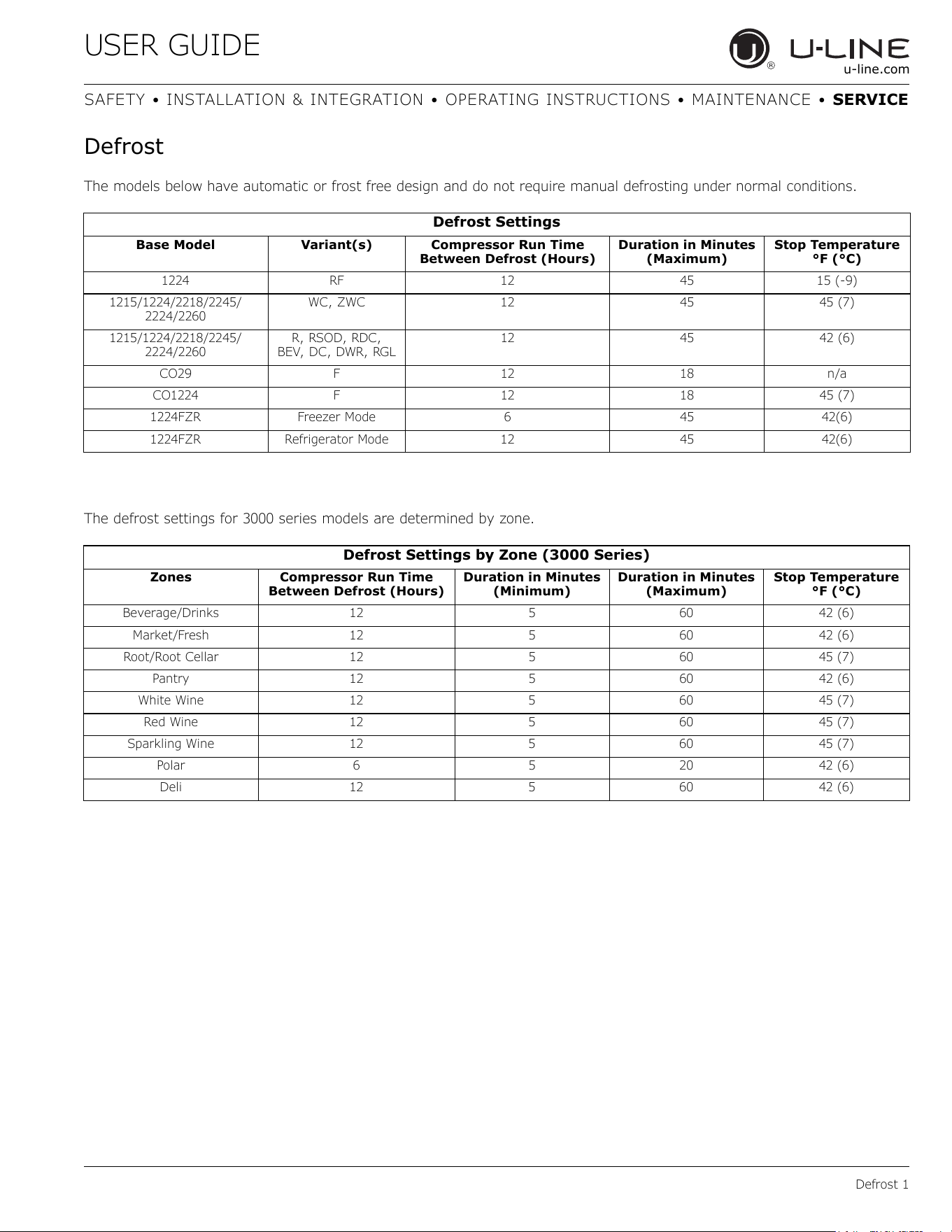
USER GUIDE
Defrost 1
u-line.com
SAFETY • INSTALLATION & INTEGRATION • OPERATING INSTRUCTIONS • MAINTENANCE • SERVICE
Defrost
The models below have automatic or frost free design and do not require manual defrosting under normal conditions.
The defrost settings for 3000 series models are determined by zone.
Defrost Settings
Base Model Variant(s) Compressor Run Time
Between Defrost (Hours)
Duration in Minutes
(Maximum)
Stop Temperature
°F (°C)
1224 RF 12 45 15 (-9)
1215/1224/2218/2245/
2224/2260
WC, ZWC 12 45 45 (7)
1215/1224/2218/2245/
2224/2260
R, RSOD, RDC,
BEV, DC, DWR, RGL
12 45 42 (6)
CO29 F 12 18 n/a
CO1224 F 12 18 45 (7)
1224FZR Freezer Mode 6 45 42(6)
1224FZR Refrigerator Mode 12 45 42(6)
Defrost Settings by Zone (3000 Series)
Zones Compressor Run Time
Between Defrost (Hours)
Duration in Minutes
(Minimum)
Duration in Minutes
(Maximum)
Stop Temperature
°F (°C)
Beverage/Drinks 12 5 60 42 (6)
Market/Fresh 12 5 60 42 (6)
Root/Root Cellar 12 5 60 45 (7)
Pantry 12 5 60 42 (6)
White Wine 12 5 60 45 (7)
Red Wine 12 5 60 45 (7)
Sparkling Wine 12 5 60 45 (7)
Polar 6 5 20 42 (6)
Deli 12 5 60 42 (6)
63
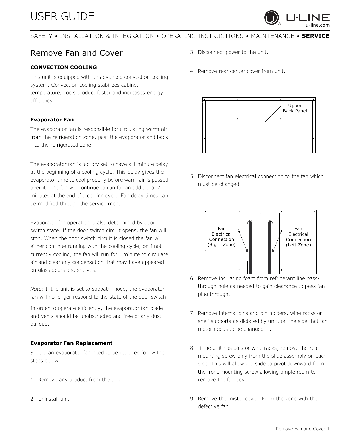
USER GUIDE
Remove Fan and Cover 1
u-line.com
SAFETY • INSTALLATION & INTEGRATION • OPERATING INSTRUCTIONS • MAINTENANCE • SERVICE
Remove Fan and Cover
CONVECTION COOLING
This unit is equipped with an advanced convection cooling
system. Convection cooling stabilizes cabinet
temperature, cools product faster and increases energy
efficiency.
Evaporator Fan
The evaporator fan is responsible for circulating warm air
from the refrigeration zone, past the evaporator and back
into the refrigerated zone.
The evaporator fan is factory set to have a 1 minute delay
at the beginning of a cooling cycle. This delay gives the
evaporator time to cool properly before warm air is passed
over it. The fan will continue to run for an additional 2
minutes at the end of a cooling cycle. Fan delay times can
be modified through the service menu.
Evaporator fan operation is also determined by door
switch state. If the door switch circuit opens, the fan will
stop. When the door switch circuit is closed the fan will
either continue running with the cooling cycle, or if not
currently cooling, the fan will run for 1 minute to circulate
air and clear any condensation that may have appeared
on glass doors and shelves.
Note: If the unit is set to sabbath mode, the evaporator
fan will no longer respond to the state of the door switch.
In order to operate efficiently, the evaporator fan blade
and vents should be unobstructed and free of any dust
buildup.
Evaporator Fan Replacement
Should an evaporator fan need to be replaced follow the
steps below.
1. Remove any product from the unit.
2. Uninstall unit.
3. Disconnect power to the unit.
4. Remove rear center cover from unit.
5. Disconnect fan electrical connection to the fan which
must be changed.
6. Remove insulating foam from refrigerant line pass-
through hole as needed to gain clearance to pass fan
plug through.
7. Remove internal bins and bin holders, wine racks or
shelf supports as dictated by unit, on the side that fan
motor needs to be changed in.
8. If the unit has bins or wine racks, remove the rear
mounting screw only from the slide assembly on each
side. This will allow the slide to pivot downward from
the front mounting screw allowing ample room to
remove the fan cover.
9. Remove thermistor cover. From the zone with the
defective fan.
Upper
Back Panel
Fan
Electrical
Connection
(Left Zone)
Fan
Electrical
Connection
(Right Zone)
64
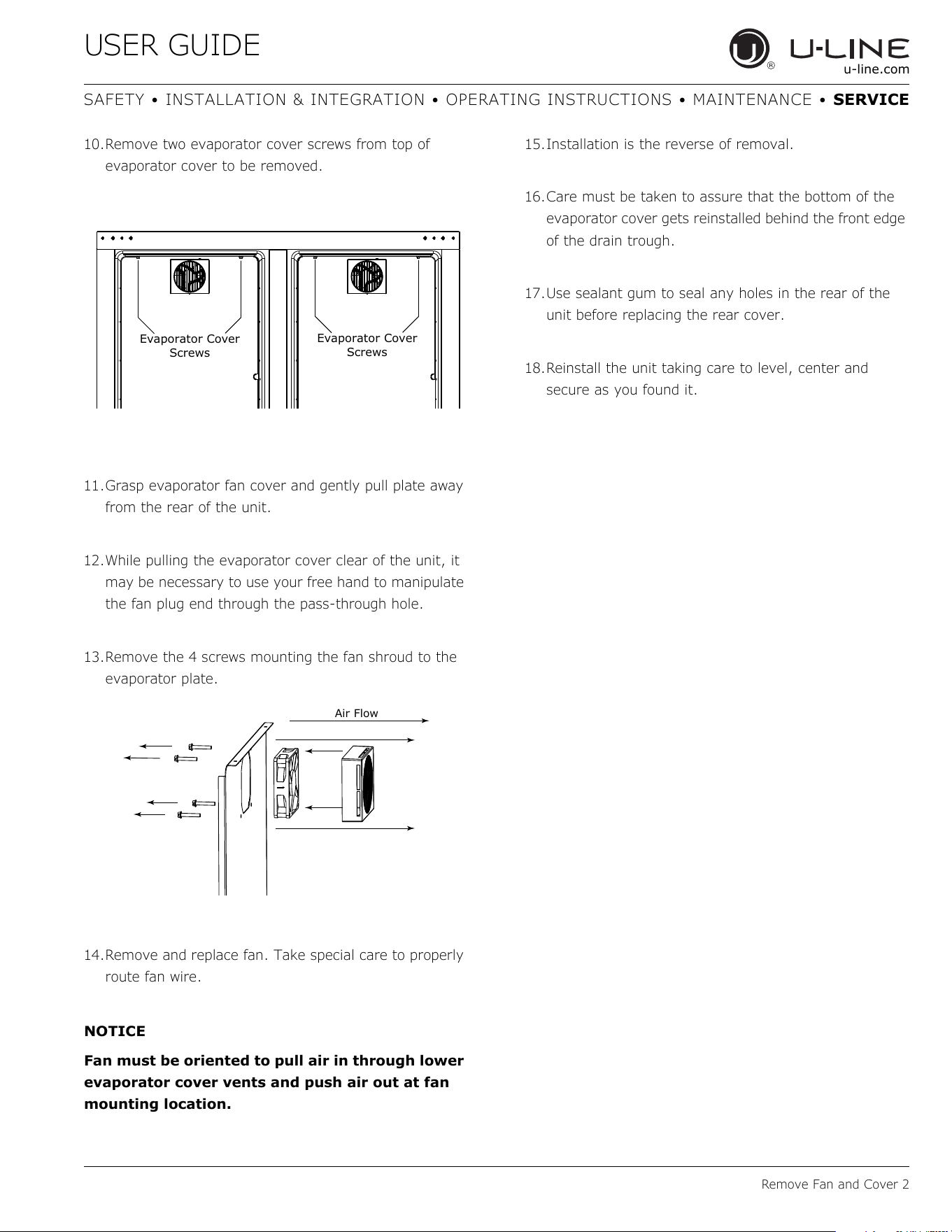
USER GUIDE
Remove Fan and Cover 2
u-line.com
SAFETY • INSTALLATION & INTEGRATION • OPERATING INSTRUCTIONS • MAINTENANCE • SERVICE
10.Remove two evaporator cover screws from top of
evaporator cover to be removed.
11.Grasp evaporator fan cover and gently pull plate away
from the rear of the unit.
12.While pulling the evaporator cover clear of the unit, it
may be necessary to use your free hand to manipulate
the fan plug end through the pass-through hole.
13.Remove the 4 screws mounting the fan shroud to the
evaporator plate.
14.Remove and replace fan. Take special care to properly
route fan wire.
NOTICE
Fan must be oriented to pull air in through lower
evaporator cover vents and push air out at fan
mounting location.
15.Installation is the reverse of removal.
16.Care must be taken to assure that the bottom of the
evaporator cover gets reinstalled behind the front edge
of the drain trough.
17.Use sealant gum to seal any holes in the rear of the
unit before replacing the rear cover.
18.Reinstall the unit taking care to level, center and
secure as you found it.
Evaporator Cover
Screws
Evaporator Cover
Screws
Air Flow
65
USER GUIDE
u-line.com
SAFETY • INSTALLATION & INTEGRATION • OPERATING INSTRUCTIONS • MAINTENANCE • SERVICE
U-Line Corporation (U-Line) Limited Warranty
One Year Limited Warranty
For one year from the date of original purchase, this U-Line product warranty covers all parts and labor to repair or replace any part of the
product that proves to be defective in materials or workmanship. For products installed and used for normal residential use, material
cosmetic defects are included in this warranty, with coverage limited to 60 days from the date of original purchase. All service provided by U-
Line under the above warranty must be performed by U-Line factory authorized service, unless otherwise specified by U-Line. Service
provided during normal business hours.
Available Second Year Limited Warranty
Beyond the standard one year warranty outlined above, U-Line offers an extension of the one year warranty coverage for an additional
second year from the date of purchase, free of charge. To take advantage of this second year warranty, you must register your product with
U-Line within two months from the date of purchase at u-line.com providing proof of purchase.
Five Year Sealed System Limited Warranty
For five years from the date of original purchase, U-Line will repair or replace the following parts, labor not included, that prove to be
defective in materials or workmanship: compressor, condenser, evaporator, drier, and all connecting tubing. All service provided by U-Line
under the above warranty must be performed by U-Line factory authorized service, unless otherwise specified by U-Line. Service provided
during normal business hours.
Terms
These warranties apply only to products installed in any one of the fifty states of the United States, the District of Columbia, or the ten
provinces of Canada. The warranties do not cover any parts or labor to correct any defect caused by negligence, accident or improper use,
maintenance, installation, service, repair, acts of God, fire, flood or other natural disasters. The product must be installed, operated, and
maintained in accordance with the U-Line User Guide.
The remedies described above for each warranty are the only ones that U-Line will provide, either under these warranties or under any
warranty arising by operation of law. U-Line will not be responsible for any consequential or incidental damages arising from the breach of
these warranties or any other warranty, whether express, implied, or statutory. Some states do not allow the exclusion or limitation of
incidental or consequential damages, so the above limitation or exclusion may not apply to you. These warranties give you specific legal
rights, and you may also have other rights which vary from state to state.
Any warranty that may be implied in connection with your purchase or use of the product, including any warranty of merchantability or any
warranty fit for a particular purpose is limited to the duration of these warranties, and only extends to five years in duration for the parts
described in the section related to the five year limited warranty above. Some states do not allow limitations on how long an implied warranty
lasts, so the above limitations may not apply to you.
• The warranties only apply to the original purchaser and are non-transferable.
• The second year and five year warranties cover products installed and used for normal residential or designated marine use only.
• The warranties apply to units operated outside only if designed for outdoor use by model and serial number.
• Replacement water filters, light bulbs, and other consumable parts are not covered by these warranties.
• The start of U-Line’s obligation is limited to four years after the shipment date from U-Line.
• In-home instruction on how to use your product is not covered by these warranties.
• Food, beverage, and medicine loss are not covered by these warranties.
• If the product is located in an area where U-Line factory authorized service is not available, you may be responsible for a trip charge
or you may be required to bring the product to a U-Line factory authorized service location at your own cost and expense.
• Units purchased after use as floor displays
, and/or certified reconditioned units, are covered by the limited one year warranty only and
no coverage is provided for cosmetic defects.
• Signal issues related to Wi-Fi connectivity are not covered by these warranties.
For parts and service assistance, or to find U-Line factory authorized service near you, contact U-Line:
8900 N. 55th Street, Milwaukee, WI 53223 • u-line.com • onlineservice@u-line.com • +1.800.779.2547
Copyright © 2014/2017 U-Line Corporation. All Rights Reserved. | Publication Number 30379 | 10/2017 Rev. L
Warranty 1
66