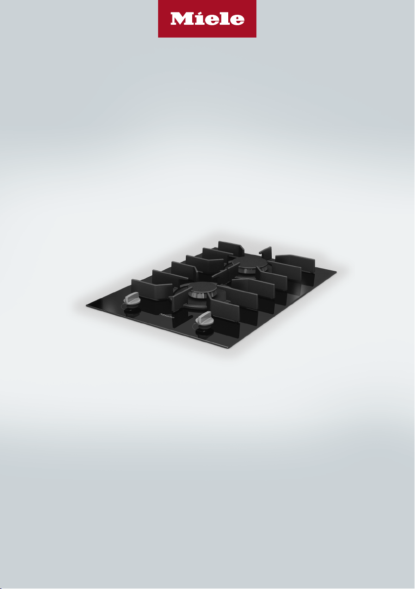
Operating and installation instructions
SmartLine gas cooktop
To prevent the risk of accidents or damage to the appliance, it is
essential to read these instructions before it is installed and used for
the first time.
en-AU, NZ M.-Nr. 11 503 520

2
This appliance can be used in countries other than those specified on the
appliance and in these operating and installation instructions. It is, however, set
up for connection to the gas and electricity supplies in the countries specified.
For trouble-free operation of the appliance, it is best to use it in the countries
specified for use.
For use in other countries, please contact Miele in your country.

Contents
3
Warning and Safety instructions.......................................................................... 5
Caring for the environment ................................................................................ 16
Overview............................................................................................................... 17
Cooktop................................................................................................................. 17
Control knobs........................................................................................................ 18
Burner.................................................................................................................... 19
Accessories supplied ............................................................................................ 20
Before using for the first time ............................................................................ 21
Cleaning the SmartLine appliance for the first time .............................................. 21
Switching on the SmartLine appliance for the first time ....................................... 21
Suitable cookware............................................................................................... 22
Notes on the use of different sized utensils .......................................................... 22
Tips on saving energy ........................................................................................ 23
Operation.............................................................................................................. 24
Switching on.......................................................................................................... 24
FlameGuard........................................................................................................... 24
Adjusting the flame................................................................................................ 25
Switching off.......................................................................................................... 25
Safety features..................................................................................................... 26
Thermo-electric flame failure device ..................................................................... 26
Cleaning and care ............................................................................................... 27
Ceramic surface .................................................................................................... 28
Control knob(s)...................................................................................................... 29
Pan supports ......................................................................................................... 29
Burner.................................................................................................................... 30
Problem solving guide ........................................................................................ 31
Optional accessories .......................................................................................... 33
Service.................................................................................................................. 34
Contact in case of fault ......................................................................................... 34
Data plate .............................................................................................................. 34
Warranty ................................................................................................................ 34
Installation............................................................................................................ 35
Safety instructions for installation ......................................................................... 35
Safety distances.................................................................................................... 36

Contents
4
Detailed dimensions.............................................................................................. 39
Surface-mounted .................................................................................................. 40
Installation notes – surface-mounted.................................................................... 40
Worktop cut-out – surface-mounted..................................................................... 42
Spacer bars – surface-mounted............................................................................ 45
Installation dimensions– Surface-mounted.......................................................... 46
Installation – surface-mounted.............................................................................. 48
Flush-fit ................................................................................................................. 50
Installation notes – flush-fit ................................................................................... 50
Worktop cut-out – flush-fit .................................................................................... 52
Spacer bars – flush-fit ........................................................................................... 55
Installation dimensions–Flush ............................................................................. 56
Installation – flush-fit ............................................................................................. 58
Gas connection ..................................................................................................... 60
Electrical connection ............................................................................................. 63
Burner ratings ...................................................................................................... 64
Conversion to another type of gas .................................................................... 65
Jet table................................................................................................................. 65
Changing the jets .................................................................................................. 65
Changing the main jets..................................................................................... 65
Changing the small jets.................................................................................... 66
Checking operation ............................................................................................... 66
Warning and Safety instructions
5
This cooktop complies with all relevant local and national safety
requirements. However, inappropriate use can lead to personal
injury and damage to property.
Read the operating and installation instructions carefully before
using the cooktop. They contain important information on safety,
installation, use and maintenance of the appliance. This prevents
both personal injury and damage to the cooktop.
In accordance with standard IEC 60335-1, Miele expressly and
strongly advises that you read and follow the instructions in
“Installation”, as well as in the “Warning and Safety instructions”.
Miele cannot be held liable for injury or damage caused by non-
compliance with these instructions.
Keep these instructions in a safe place and pass them on to any
future owner.

Warning and Safety instructions
6
Correct application
This cooktop is designed for domestic use and for use in similar
environments by guests in hotel or motel rooms, bed & breakfasts
and other typical living quarters. This does not include common/
shared facilities or commercial facilities within hotels, motels or bed
& breakfasts.
This cooktop is not suitable for outdoor use.
It is intended only to cook food and keep it warm. Any other use is
not supported by Miele and could be dangerous.
This cooktop is not intended for use by people (including children)
with reduced physical, sensory or mental capabilities or lack of
experience and knowledge, unless they have been given supervision
and instruction concerning its use by a person responsible for their
safety. They may only use the cooktop unsupervised if they have
been shown how to use it in a safe way. They must be able to
recognise and understand the potential dangers of improper use.

Warning and Safety instructions
7
Safety with children
Young children must not be allowed to use this appliance.
Older children may only use the appliance if its operation has
been clearly explained to them and they are able to use it safely.
They must be aware of the potential dangers caused by incorrect
operation.
Cleaning may only be carried out by older children under the
supervision of an adult.
Please supervise children in the vicinity of the cooktop and do not
let them play with it.
The cooktop gets hot when in use and remains hot for a while
after being switched off. Keep children well away from the cooktop
until it has cooled down and there is no danger of burning.
Danger of burning! Do not store anything which might arouse a
child's interest in storage areas above or behind the cooktop.
Otherwise children could be tempted to climb onto the cooktop with
the risk of burning themselves.
Danger of burning and scalding! Turn the handles of pots and
pans on the cooktop to the side or the rear so that children cannot
pull them down and burn themselves.
Danger of suffocation! Whilst playing, children may become
entangled in packaging material (such as plastic wrapping) or pull it
over their head with the risk of suffocation. Keep packaging material
away from children.

Warning and Safety instructions
8
Technical safety
Unauthorised installation, maintenance and repairs (including
removal of any cover) can cause considerable danger for the user.
Installation, maintenance and repairs must only be carried out by a
Miele authorised technician.
Damage to the cooktop can compromise your safety. Check the
appliance for visible signs of damage. Do not use the cooktop if it is
damaged.
Reliable and safe operation of this cooktop can only be assured if
it has been connected to the mains electricity supply.
The electrical safety of this appliance can only be guaranteed
when continuity is complete between it and an effective earthing
system which complies with local and national safety regulations. It
is most important that this basic safety requirement is present and
tested regularly and, where there is any doubt, the household wiring
system should be inspected by a qualified electrician.
Before connecting the appliance to the mains electricity supply,
ensure that the connection data on the data plate (voltage and
frequency) matches the mains electricity supply. This data must
correspond in order to avoid the risk of damage to the appliance.
Do not connect the cooktop to the mains electricity supply by a
multi-socket adapter or extension lead. These are a fire hazard and
do not guarantee the required safety of the appliance.
For safety reasons, this cooktop may only be used after it has
been built in.
This appliance must not be installed and operated in mobile
installations (e.g. on a ship).
Never open the casing of the cooktop.
Touching or tampering with electrical connections or components
and mechanical parts is highly dangerous to the user and can cause
operational faults.

Warning and Safety instructions
9
The manufacturer's warranty will be invalidated if the appliance is
not repaired by a Miele authorised service technician.
Faulty components must only be replaced by genuine Miele spare
parts. The manufacturer can only guarantee the safety of the
appliance when Miele replacement parts are used.
The cooktop is not intended for use with an external timer switch
or a remote control system.
The connection to the gas supply must be carried out by a
suitably qualified gas fitter (see “Installation - Gas connection”). If the
plug has been removed from the connection cable or or the
connection cable is not supplied with a plug, the cooktop must be
connected to the electricity supply by a suitably qualified electrician
(see “Installation – Electrical connection”).
If the mains connection cable is damaged, it must be replaced
with a special mains connection cable, available from Miele, by a
Miele authorised service technician or suitably qualified and
competent electrician in order to avoid a hazard (see “Installation -
Electrical connection”).
During installation, maintenance and repair work, the appliance
must be completely disconnected from the mains electricity supply.
The gas supply must also be turned off. It is only completely isolated
from the gas and electricity supply when:
– the mains circuit breaker is switched off, or
– it is switched off at the wall socket and the plug is withdrawn from
the socket. Do not pull the mains connection cable but the mains
plug to disconnect your appliance from the mains electricity
supply.
– the gas inlet valve is closed.

Warning and Safety instructions
10
Danger of electric shock! If the ceramic surface is faulty, cracked,
chipped or damaged in any way, do not use the cooktop or switch it
off immediately. Disconnect it from the mains electricity and gas
supply. Contact Miele.
If the cooktop is installed behind a furniture door, do not close the
door while the cooktop is in operation. Heat and moisture can build
up behind the closed door. This can result in damage to the cooktop,
the housing unit and the floor. Leave the furniture door open until the
cooktop has cooled down completely.
In areas which may be subject to infestation by cockroaches or
other vermin, pay particular attention to keeping the appliance and
its surroundings clean at all times. Any damage caused by
cockroaches or other vermin will not be covered by the warranty.
DO NOT MODIFY THIS APPLIANCE.
This cooktop is not suitable for installation and operation with
aftermarket lids or covers fitted.

Warning and Safety instructions
11
Correct use
The appliance gets hot when in use and remains hot for some
time after being switched off. Do not touch the appliance if there is a
possibility that it could still be hot.
DO NOT USE THIS APPLIANCE AS A SPACE HEATER.
Oil and fat can overheat and catch fire. Do not leave the cooktop
unattended when cooking with oil and fat. If it does ignite, do not
attempt to put the flames out with water.
Switch off the cooktop and use a suitable fire blanket, saucepan lid,
damp towel or similar to smother the flames.
The cooking process has to be supervised. A short term cooking
process has to be supervised continuously.
Flames could set the grease filters of a rangehood on fire. Do not
flambé under a rangehood.
Spray canisters, aerosols and other inflammable substances can
ignite when heated. Therefore do not store such items or substances
in a drawer under the cooktop. Cutlery inserts must be heatresistant.
DO NOT USE OR STORE FLAMMABLE MATERIALS IN THE
APPLIANCE STORAGE DRAWER OR NEAR THIS APPLIANCE.
CUTLERY INSERTS MUST BE HEAT-RESISTANT.
DO NOT SPRAY AEROSOLS IN THE VICINITY OF THIS
APPLIANCE WHILE IT IS IN OPERATION.
DO NOT PLACE ARTICLES ON OR AGAINST THIS APPLIANCE.
Do not use or store flammable materials near this appliance.
Do not use the appliance to heat up the room.
Due to the high temperatures radiated, objects left near the
appliance could catch fire.
Do not heat an empty pan.

Warning and Safety instructions
12
Do not heat up food in closed containers e.g. tins or sealed jars
on the cooktop, as pressure can build up in the containers, causing
them to explode.
Do not cover the cooktop, e.g. with a cooktop cover, a cloth or
protective foil. The material could catch fire, shatter or melt if the
cooktop is switched on by mistake or if residual heat is still present.
When the appliance is switched on either deliberately or by
mistake, or when there is residual heat present, there is the risk of
any metal items placed on the cooktop (e.g. cutlery) heating up.
Depending on the material, other items left on the appliance could
also melt or catch fire. Do not use the appliance as a resting place
for anything else.
You could burn yourself on the hot appliance. Protect your hands
with heat-resistant pot holders or gloves when handling hot pots and
pans. Do not let them get wet or damp, as this causes heat to
transfer through the material more quickly with the risk of scalding or
burning yourself on steam. Be sure to keep all textiles away from the
gas flames. Do not use oversized cloths, tea towels or other similar
materials.
When using an electrical appliance, e.g. a hand-held food mixer,
near the cooktop, ensure that the cable of the electrical appliance
cannot come into contact with the hot cooktop. The insulation on the
cable could become damaged.
Even a light object can cause damage in certain circumstances.
Do not drop anything on the ceramic surface.
Plastic and aluminium foil containers melt at high temperatures.
Do not use plastic or aluminium foil containers on the cooktop.
When a control knob is pressed down, a spark is generated on the
ignitor. Do not press down the control knob while you are cleaning or
touching the cooktop or a burner in the vicinity of an ignitor.

Warning and Safety instructions
13
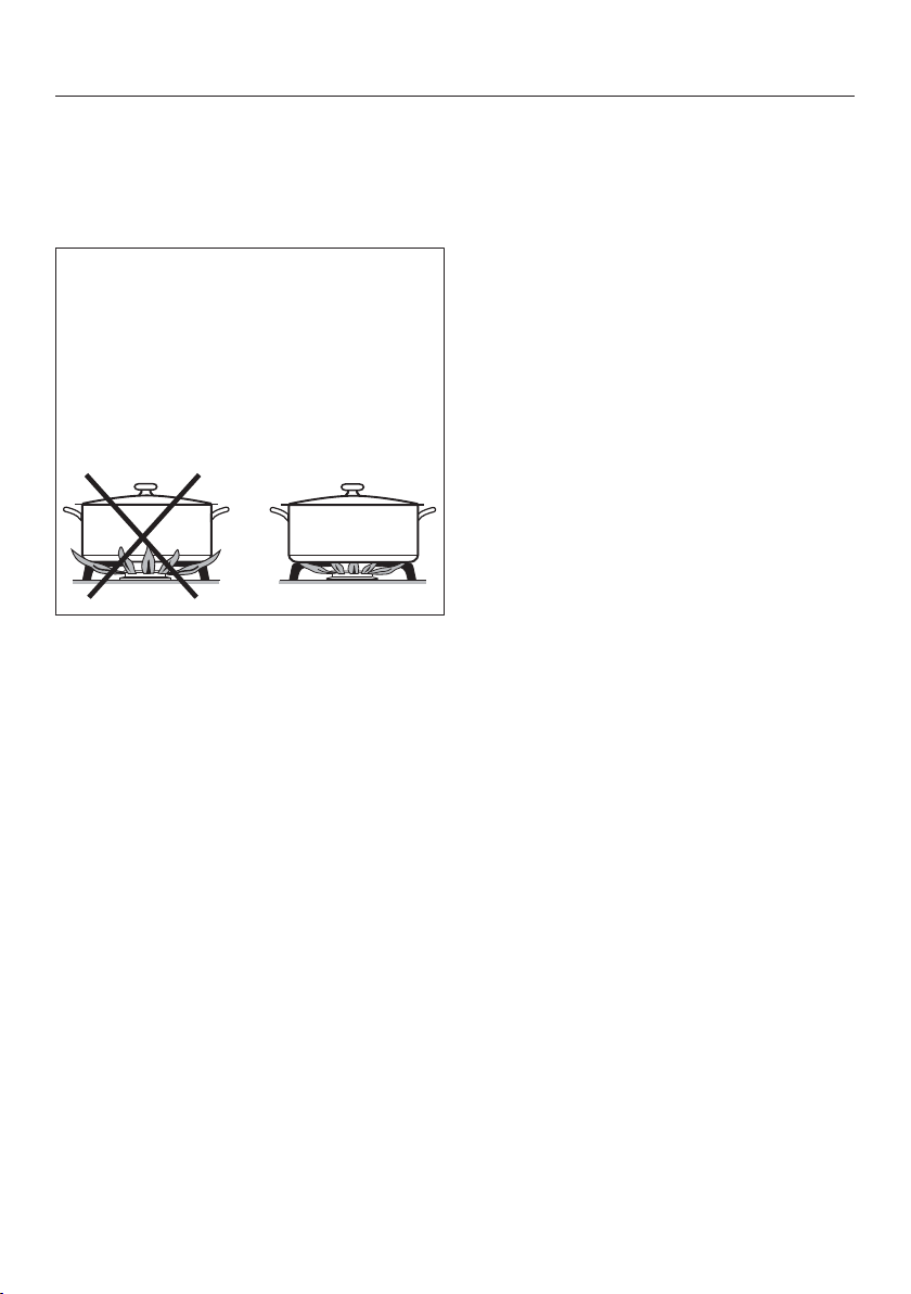
If a rangehood is installed above the cooktop, ensure that the
burners are always covered with a pan when in use. Otherwise
flames could reach the rangehood, parts of which could then be
damaged or even set on fire.
Switch the burner off when a pan is removed, even for a short
time.
Make sure all the components of the gas burner have been
correctly assembled before switching on.
Pans must be the correct size for the burner they are used on (see
“Suitable cookware”). A pan which is too small will be unstable on
the pan support. If the pan diameter is too large, flames can spread
out to the sides and damage or burn the worktop, wall claddings or
surrounding units and also parts of the cooktop. Miele cannot be
held liable for this type of damage.
Ensure that the flames from the burner do not spread out beyond
the base and up the sides of the pan.
Do not use pans with very thin bases on this cooktop, and never
heat up empty pans as they could get damaged. This could also
damage the appliance.
The pan supports supplied with the appliance must always be
used. Never place a pan on the burner itself.
Replace the pan supports carefully to avoid scratching the surface
of the cooktop.
Remove all grease spatters and other combustible (food) residues
from the cooktop as soon as possible. They are a fire hazard.
The use of the gas cooktop creates heat, moisture and
combustion products in the room where it is installed. Make sure
that the appliance is installed in a location with sufficient ventilation.
Natural ventilation openings should not be blocked. Alternatively, a
mechanical ventilation device (e.g. a rangehood) can be installed.

Warning and Safety instructions
14
If the cooktop is used for very long periods of time, additional
ventilation of the room may be necessary, e.g. by opening windows
or doors, or running the rangehood on the highest setting.
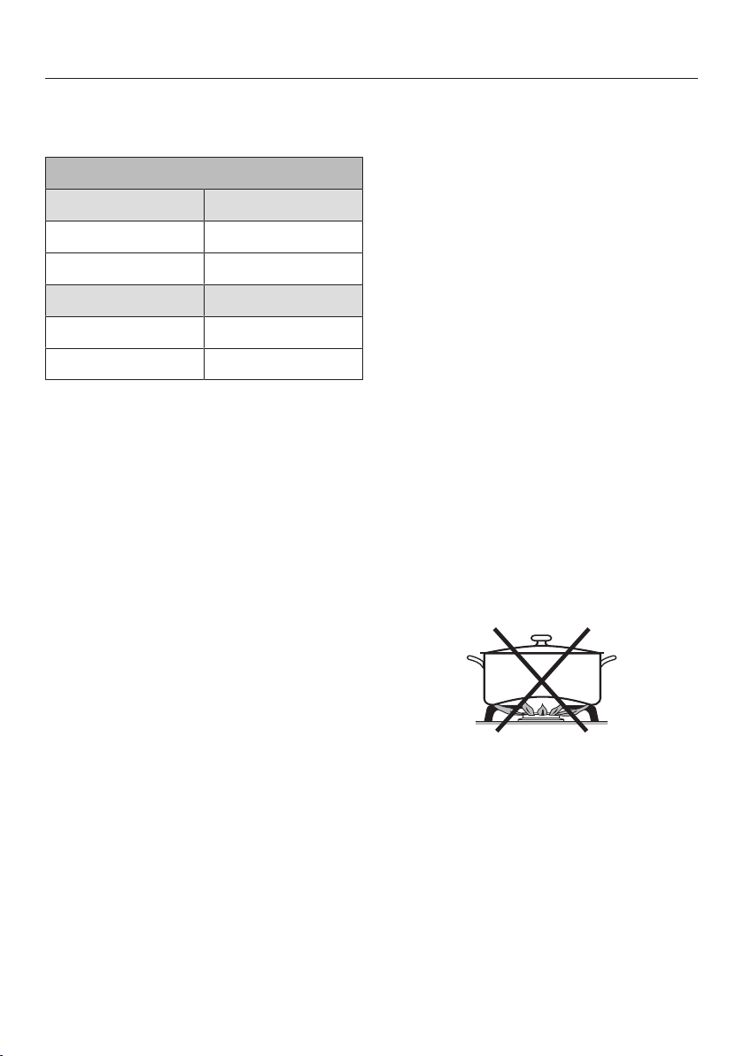
Do not use roasting dishes, pans or grilling stones that are large
enough to cover more than one burner. The resulting build-up of
heat could damage the appliance.
If the appliance has not been used for a long period of time it
should be thoroughly cleaned before it is used again. It is also
advisable to have the appliance tested by a qualified person for
safety.
If you are operating a gas cooking appliance directly next to the
downdraft extractor, the FlameGuard must be placed between the
downdraft extractor and the appliance.

Warning and Safety instructions
15
Cleaning and care
Do not use a steam cleaning appliance to clean this appliance.
The steam could reach the electrical components and cause a short
circuit.
Caring for the environment
16
Disposal of the packing
material
The transport and protective packaging
has been selected from materials which
are environmentally friendly for
disposal, and can normally be recycled.
Recycling the packaging reduces the
use of raw materials in the
manufacturing process and also
reduces the amount of waste in landfill
sites. Ensure that any plastic
wrappings, bags etc. are disposed of
safely and kept out of the reach of
babies and young children. Danger of
suffocation.
Disposing of your old
appliance
Electrical and electronic appliances
often contain valuable materials. They
also contain specific materials,
compounds and components, which
were essential for their correct function
and safety. These could be hazardous
to human health and to the environment
if disposed of with your domestic waste
or if handled incorrectly. Please do not,
therefore, dispose of your old appliance
with your household waste.
Please dispose of it at your local
community waste collection / recycling
centre for electrical and electronic
appliances. You are also responsible for
deleting any personal data that may be
stored on the appliance prior to
disposal. Please ensure that your old
appliance poses no risk to children
while being stored prior to disposal.
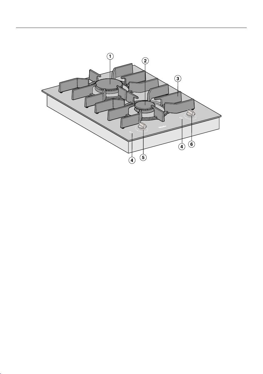
Overview
17
Cooktop
a
Burner
b
Burner
c
Pan supports
d
Symbols for allocation of controls
e
Control for rear burner
f
Control for front burner
Overview
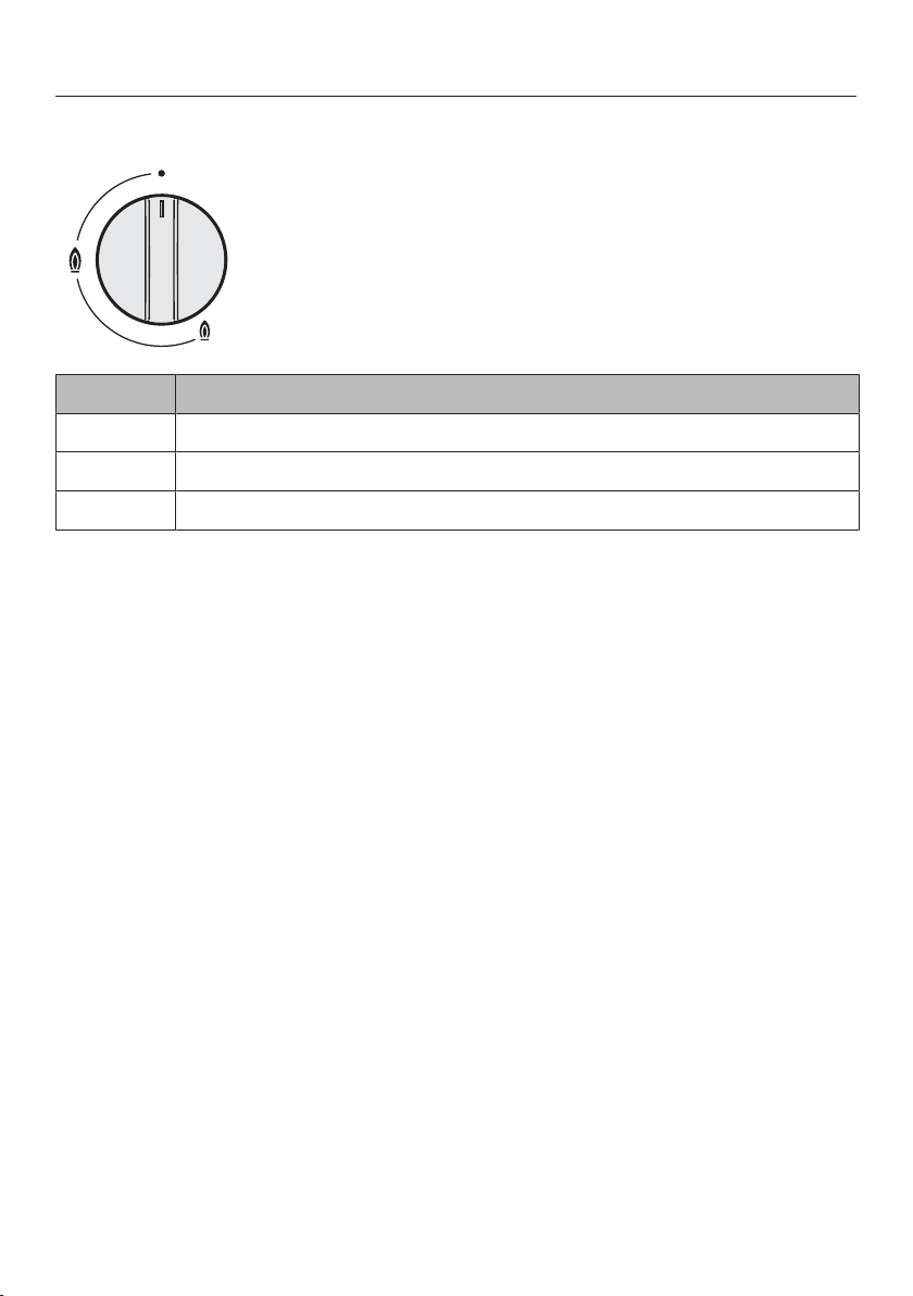
18
Control knobs
Symbol Description
Burner off, the gas supply is turned off
Strongest flame
Weakest flame
Overview
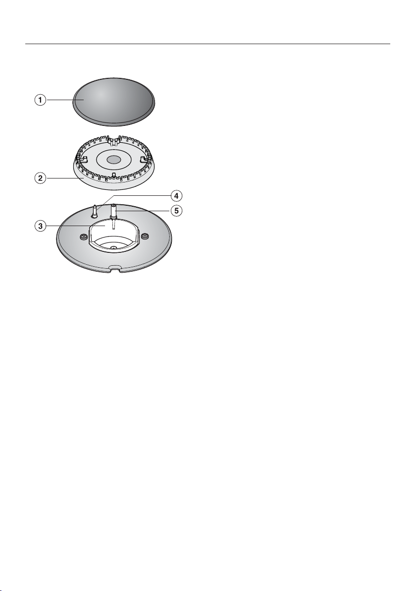
19
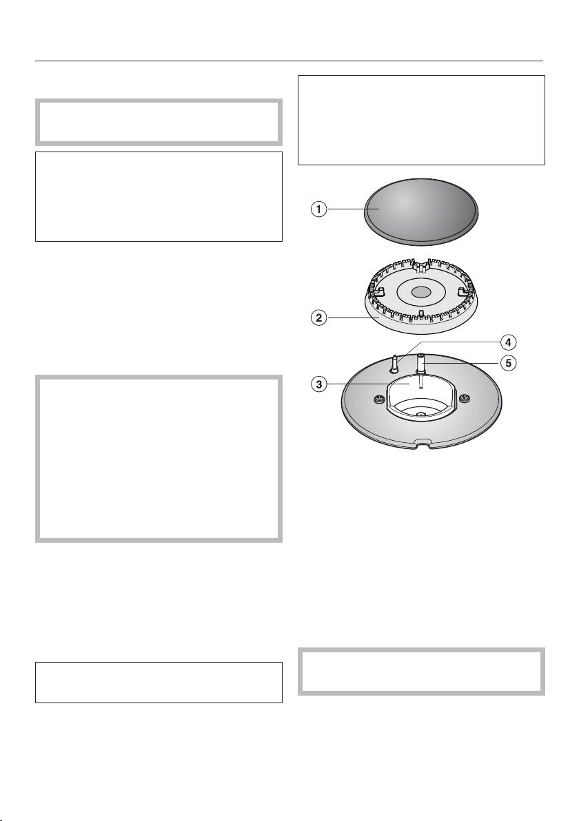
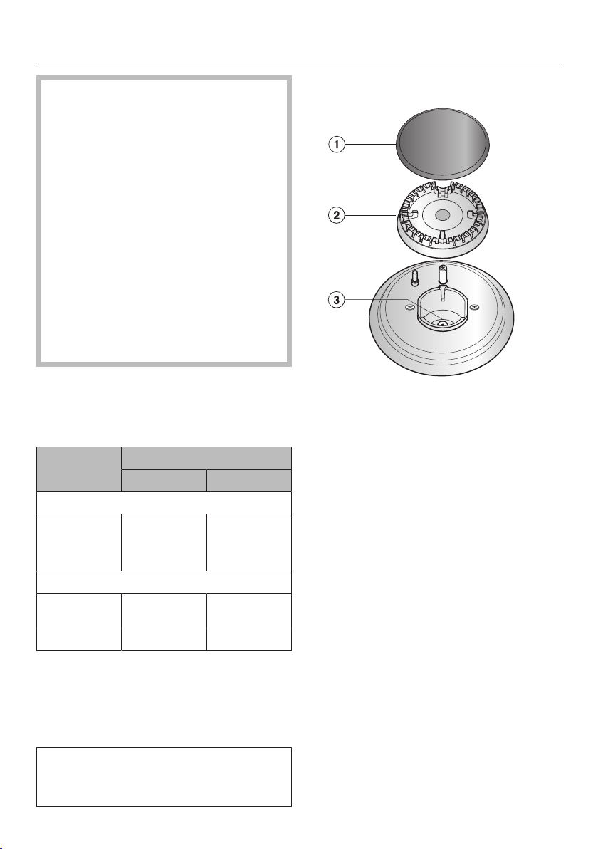
Burner
a
Burner cap
b
Burner head
c
Burner base
d
Flame failure device
e
Ignitor
Overview
20
Accessories supplied
The accessories supplied with your
appliance, as well as a range of optional
ones, are available to order from Miele
(see “Optional accessories”).
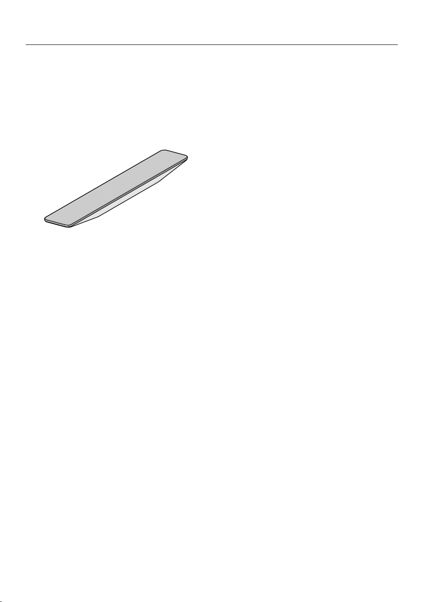
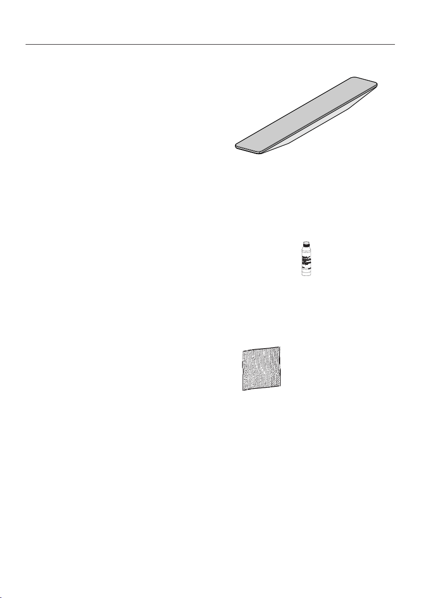
FlameGuard
For fitting in place between the
downdraft extractor and a gas cooking
appliance.

Before using for the first time
21
Please stick the extra data plate for
the appliance supplied with this
documentation in the space provided
in the “Service” section of this
booklet. Alternatively, the additional
label can be stuck near the appliance
if the appliance markings are not
visible after installation.
Remove any protective wrapping and
stickers (except the data plate).
Cleaning the SmartLine
appliance for the first time
Clean all removable parts of the
burner(s) with a solution of warm
water and a small amount of
washing-up liquid applied with a soft
sponge. Dry all parts thoroughly after
cleaning and then reassemble the
burners (see “Cleaning and care -
Burners”).
Clean the ceramic surface with a
damp cloth, and then wipe dry.
Switching on the SmartLine
appliance for the first time
The metal components have a
protective coating. Smells and possibly
some vapours may occur when the
SmartLine appliance is used for the first
time.
The smell and any vapours given off do
not indicate a faulty connection or
appliance and they are not hazardous
to health.
Suitable cookware
22
Notes on the use of different
sized utensils
Ø Pan [cm]
Burner Minimum at base
Normal burner 12
Extra fast burner 14
Burner Maximum at top
Normal burner 22
Extra fast burner 24
– Select cookware that fits the size of
the burner:
large diameter = large burner
small diameter = small burner
– Refer to the chart above and ensure
that the pan diameter falls within the
minimum and maximum diameters
given for the burner you are using.
Using cookware that is too large can
cause the flames to spread out and
damage or burn the worktop, wall
claddings or surrounding units and
also parts of the cooktop or other
appliances. Using pans of the correct
size improves efficiency.
Any cookware that has a diameter
smaller than the pan supports or that
does not rest safely (without
wobbling) on the pan supports is
dangerous and should not be used.
– Unlike pans that are used on an
electric cooktop, the bottom of pans
used on a gas cooktop do not have
to be flat to deliver good cooking
results.
– Remember when purchasing new
pans that manufacturers usually refer
to the diameter at the top of the pan
in their documentation.
– Any heat-resistant cookware can be
used on a gas burner.
– Cookware with a thick base is
preferable, as it distributes heat more
evenly. Cookware with a thin base
may cause food to overheat in some
places. To avoid this, stir the food
frequently.
– Always place cookware on the pan
supports supplied with the appliance.
Never place it directly on the burners.
– Position the cookware centrally on
the pan support so that it sits
securely and cannot tip. There might
still be slight movement, which is not
a cause for concern.
– Do not use pots or pans with base
supports.

Tips on saving energy
23
– Use a pan lid whenever possible to
minimise heat loss.
– Wide, shallow pans are preferable to
tall, narrow ones. They will heat up
faster.
– Cook with as little water as possible.
– Reduce the power setting once the
water has come to the boil or the oil
is hot enough to fry in.
– Use a pressure cooker to reduce
cooking times.
Operation
24
Switching on
If you are operating a gas cooking
appliance next to a downdraft
extractor, this will affect the gas
cooking appliance's function.
Place the FlameGuard between the
gas cooking appliance and the
downdraft extractor.
Risk of fire with overheated food!
Unattended food can overheat and
ignite.
Do not leave the cooktop unattended
whilst it is being used.
Press in the relevant control knob and
turn it anti-clockwise to the large
flame symbol. The ignition electrode
will “click” and ignite the gas.
When a control knob is activated, a
spark is automatically generated on all
burners. This is normal and does not
indicate a fault.
When a flame is visible, keep the
control knob pressed in for 5–
10seconds, and then let it go.
If the burner has not ignited or goes
out, turn the control knob to the
position. Aerate the room or wait for
at least oneminute before trying
again. Try keeping the control knob
pressed in for a little longer the next
time.
If the burner does not ignite the
second time, turn the control back to
the position and see “Problem
solving guide”.
Switching on during a power outage
If there is an interruption to the
electricity supply, the gas can be
ignited manually, e.g. with a match.
Press down the relevant control knob
and turn it anti-clockwise to the large
flame symbol.
Hold the control knob pressed down
and light the gas at the burner with a
match.
Keep the control knob pressed down
for a further 5-10seconds and then
release it.
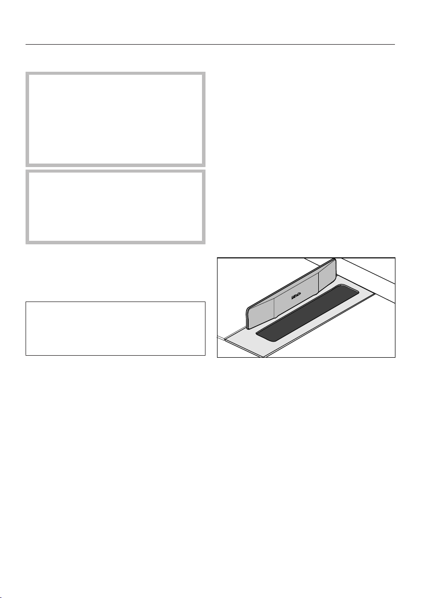
FlameGuard
Fit the magnetic FlameGuard in
position next to the downdraft
extractor when you are operating a
gas cooking appliance directly next to
the extractor.
Operation
25
Adjusting the flame
The burners can be regulated at any
level between the strongest and
weakest flame.
As the outer part of the flame is much
hotter than the centre, the tips of the
flames should stay beneath the pan
base. Flame tips which extend beyond
the sides of the pan merely warm up
the air in the room and can also
damage pan handles and increase the
danger of injury.
Adjust the flame so that it does not
spread out beyond the sides of the
pan.
Switching off
Turn the control knob clockwise to
the position.
This stops the flow of gas and
extinguishes the flame.
Safety features
26
Thermo-electric flame failure
device
Your cooktop is equipped with a
thermo-electric flame failure device. If
the gas flame is extinguished, e.g. by
food boiling over or by a draught, the
gas supply is switched off. This
prevents the release of gas. If you turn
the control knob to the position, the
burner is ready for use again.
The thermo-electric flame failure
device operates independently from
the electricity supply. This means that
it will still work if the cooktop is used
during a power cut.
Cleaning and care
27
Risk of burning due to hot
surfaces.
The cooktop surface, pan supports
and burners will be hot after use.
Allow the cooktop to cool down
before cleaning it.
Risk of damage due to moisture
ingress.
The steam from a steam cleaning
appliance could reach live electrical
components and cause a short
circuit.
Do not use a steam cleaner to clean
the cooktop.
All surfaces could be discoloured or
damaged if unsuitable cleaning
agents are used. All surfaces are
susceptible to scratching.
Remove all cleaning agent residues
immediately.
Never use abrasive sponges or
cleaning agents.
Food boiling over on a hot cooktop
can cause discoloration of the burner
components.
Remove any soiling and salt and
sugar splashes immediately.
When a control knob is pressed
down, a spark is generated on the
ignitor. Do not press down the
control knob while you are cleaning
or touching the cooktop or a burner
in the vicinity of an ignitor.
Allow the SmartLine appliance to
cool down before cleaning.
Clean the SmartLine appliance and
accessories after each use.
Dry the SmartLine appliance
thoroughly every time after cleaning
to avoid limescale residue.
Unsuitable cleaning agents
To avoid damaging the surfaces of the
appliance, do not use:
– cleaning agents containing soda,
alkalines, ammonia, acids or
chlorides
– cleaning agents containing descaling
agents
– stain and rust removers
– abrasive cleaning agents, e.g.
powder cleaners and cream cleaners
– solvent-based cleaning agents
– dishwasher cleaner
– oven sprays
– grill and oven cleaners
– glass cleaning agents
– hard, abrasive brushes or sponges
(e.g. pot scourers), or sponges which
have been previously used and still
contain abrasive cleaning agents
– dirt erasers
Cleaning and care
28
Ceramic surface
Risk of damage by pointed
objects.
The seal between the SmartLine
appliance and the worktop could
suffer damage.
Do not use pointed objects for
cleaning.
Do not use washing-up liquid to
clean the appliance. Using washing-
up liquid will not remove all soiling
and residues.
Cleaning with washing-up liquid can
result in an invisible film that can lead
to discolouration of the ceramic
glass. This discolouration cannot be
removed.
Clean the ceramic surface regularly
with a proprietary ceramic glass
cleaning agent.
Remove any coarse soiling with a
damp cloth and more stubborn
soiling with a glass scraper.
Then clean the ceramic glass surface
with the Miele ceramic and stainless
steel cooktop cleaner (see “Optional
accessories”) or with a proprietary
ceramic glass cleaner applied with
kitchen paper or a clean cloth. Do not
apply the cleaner while the cooktop is
still hot, as this can result in marking.
Please follow the cleaning agent
manufacturer's instructions.
Finally wipe the cooktop with a damp
cloth and dry it with a soft, dry cloth.
Residues can burn onto the cooktop
the next time it is used and cause
damage to the glass ceramic surface.
Ensure that all cleaner residues are
removed.
Spots caused by limescale, water
and aluminium residues (spots with a
metallic appearance) can be removed
using the Miele ceramic and stainless
steel cooktop cleaner.
Risk of burning due to hot
surfaces.
The surfaces get hot during use.
Wear oven gloves when removing
residues of sugar, plastic or
aluminium foil from a hot cooktop
with a glass scraper.
Should any sugar, plastic or
aluminium foil spill or fall onto a hot
cooking zone while it is in use, first
switch off the appliance.
Then carefully scrape off these
residues immediately whilst they are
still hot, using a shielded scraper
blade suitable for use on glass.
Afterwards, clean the glass ceramic
surface in its cooled state, as
described above.

Cleaning and care
29
Control knob(s)
Clean the control knob(s) using a
solution of warm water and a little
washing-up liquid applied with a soft
sponge. Stubborn soiling should be
soaked first.
Dry the control knob(s) with a clean
cloth.
Pan supports
Remove the pan supports.
Clean the pan supports in the
dishwasher or with a solution of warm
water and a little washing-up liquid
applied with a soft sponge. Stubborn
soiling should be soaked first.
After cleaning, dry the pan supports
thoroughly with a clean cloth.
Cleaning and care
30
Burner
Do not clean any parts of the burners
in a dishwasher.
The surface of the burner caps will
become more matt over time. This is
normal and does not indicate damage
to the burner caps. Nor will it affect
the operation of the cooktop.
The burner should be dismantled and
then cleaned by hand using a
solution of warm water and a little
dishwashing liquid applied with a soft
sponge.
Clean any soiling from the flame
openings.
Danger of explosion!
Blocked flame openings can cause a
dangerous build-up of gas in the
base of the cooktop which could
ignite and cause an explosion. This
can lead to damage to the appliance
and injury.
Ensure the flame openings are kept
clean at all times.
Parts of the burner that cannot be
removed should be wiped clean with
a damp cloth only.
The ignitor and the flame failure
device should be very carefully wiped
clean using a well wrung out cloth.
Do not let the ignitor get wet. If it gets
wet, it will not spark.
Finally dry everything thoroughly with
a clean cloth. Make sure that the
flame openings are completely dry.
The surface of the burner caps will
become more matt over time. This is
normal and does not indicate damage
to the burner caps. Nor will it affect
the operation of the cooktop.
Place the burner head onto the
burner base so that the flame
failure device and the ignitor
extend through their respective holes
in the burner head. The burner head
must click into place correctly.
Place the burner cap flat over the
burner head. When correctly
positioned, the burner cap will not
slide about.
Ensure that all parts of the burner are
reassembled in the correct order.
Problem solving guide
31
With the help of the following guide, minor faults in the performance of the
appliance, some of which may result from incorrect operation, can be remedied
without contacting Miele. This will save you time and money because you won't
need a service call.
Please note that a call-out charge will be applied to unnecessary service visits
where the problem could have been rectified as described in these operating
instructions.
Problem Possible cause and remedy
The burner does not
ignite when the cooktop
is being used for the
first time or after it has
not been used for a
longer period.
There could be an air lock in the gas pipe.
You may need to make several attempts before the
burner ignites successfully.
The burner does not
light after several
attempts.
There is a fault.
Turn all of the control knobs clockwise to the
position and interrupt the power supply to the
cooktop for a few seconds.
The burner is not correctly assembled.
Assemble the burner correctly.
The gas shut-off valve is closed.
Open the gas shut-off valve.
The burner is wet and/or dirty.
Clean and dry the burner.
The flame openings are blocked and/or wet.
Clean and dry the flame openings.
The gas flame goes out
after being lit.
The flames do not touch the flame failure device and
the burner does not get hot enough:
The burner parts are not positioned correctly.
Position the burner parts correctly.
The flame failure device is dirty.
Remove any soiling.
The flame suddenly
looks different.
The burner parts are not positioned correctly.
Position the burner parts correctly.
The burner head or the holes in the burner cap are
dirty.
Remove any soiling.
Problem solving guide
32
Problem Possible cause and remedy
The gas flame goes out
during operation.
The burner parts are not positioned correctly.
Position the burner parts correctly.
The ignitor on the
burner does not spark.
The mains circuit breaker has tripped.
If it has, contact a qualified electrician or Miele.
There is food residue stuck between the ignitor and
the burner cap.
The flame failure device is dirty.
Remove any soiling (See “Cleaning and care”).
Optional accessories
33
Miele offers a range of useful
accessories, as well as cleaning and
conditioning products for your
appliance.
These products can be ordered from
the Miele online shop.
They can also be ordered directly from
Miele (see end of this booklet for
contact details).
FlameGuard
For fitting in place between the
downdraft extractor and a gas cooking
appliance.
Original Miele ceramic and
stainless steel cleaner 250ml
Removes heavy soiling, limescale
deposits and aluminium residues.
Original Miele all purpose
microfibre cloth
Removes finger marks and light soiling.
Service
34
Contact in case of fault
In the event of any faults which you cannot remedy yourself, please contact Miele.
Contact information for Miele can be found at the end of this booklet.
Please quote the model and serial number of your appliance when contacting
Miele. This information can be found on the data plate.
Data plate
Adhere the extra data plate supplied with the appliance in the space below. Make
sure that the model number matches the one specified on the back cover of these
operating and installation instructions.
Warranty
The manufacturer's warranty for this appliance is 2years.
For further information, please refer to your warranty booklet.

Installation
*INSTALLATION*
35
Safety instructions for installation
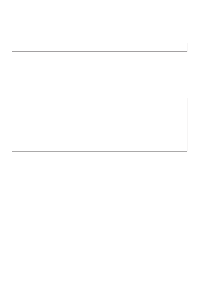
Damage from falling objects.
Take care not to damage the SmartLine appliance when fitting wall units or a
rangehood above it.
Fit the wall units and the rangehood before the SmartLine appliance.
The room in which the SmartLine appliance is installed must
conform to all relevant local and national building regulations and
safety regulations.
In Australia and New Zealand, gas installations must be in
accordance with AS/NZS 5601.
The veneer or laminate coatings of worktops (or adjacent kitchen
units) must be treated with 100°C heat-resistant adhesive which will
not dissolve or distort. Any splashbacks must be of heat-resistant
material.
An electric fryer must not be installed directly next to a gas
cooktop as the gas flames could ignite the fat in the fryer. It is
essential to maintain a distance of at least 288mm between these
two appliances.
The SmartLine appliance must not be installed over a fridge,
fridge-freezer, freezer, dishwasher, washing machine, washer-dryer
or tumble dryer.
When installing the SmartLine appliance, make sure that the gas
pipe and mains connection cable cannot come into contact with hot
appliance parts.
The mains connection cable and any flexible gas connection pipes
must be installed in such a way so that they do not come into
contact with any moving kitchen parts (e.g. a drawer) after the
SmartLine appliance has been installed, and that they cannot be
subjected to any mechanical action which could cause damage.
Carefully observe the safety clearances listed on the following
pages.
Installation
*INSTALLATION*
36
Safety distances
Safety distance above the SmartLine
A minimum safety distance must be
maintained between the SmartLine and
the rangehood above it. See the
rangehood manufacturer's operating
and installation instructions for details.
If the manufacturer's instructions are
not available for the rangehood, a
minimum safety distance
as per AS/NZS 5601.1 must be
maintained.
For any flammable objects, e.g. utensil
rails, wall units etc., a minimum safety
distance of 600mm must be
maintained between these objects and
the highest part of the SmartLine below.
When two or more appliances which
have different safety distances are
installed together below a
rangehood, you should observe the
greatest safety distance.
Clearance underneath the appliance
A minimum safety clearance of 30mm
must be provided underneath the
appliance.
Please note that clearance must also be
provided for the installation of the
flexible gas connection hose and mains
electrical cable if the appliance is to be
installed above a closed surface (e.g.
an oven).
Installation
*INSTALLATION*
37
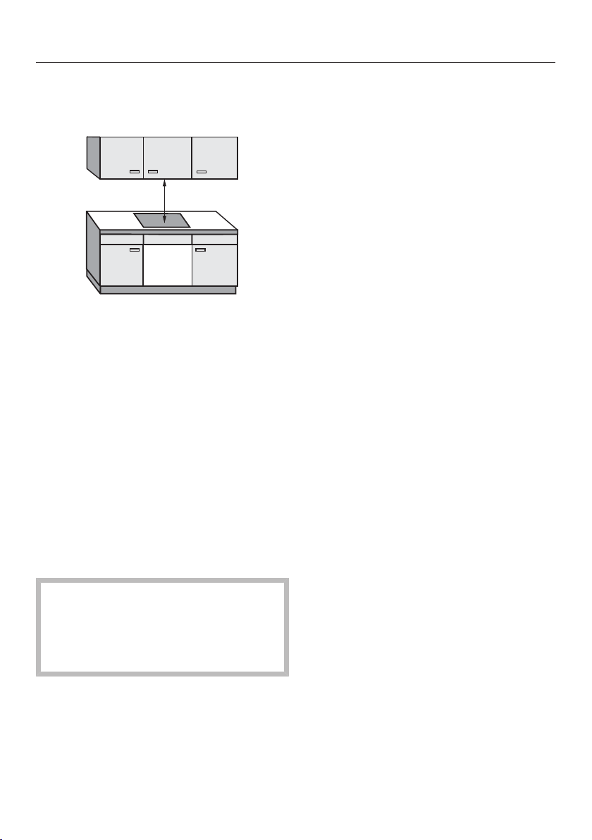
Safety distances to the sides and
back of the appliance
Ideally the appliance should be installed
with plenty of space on either side.
There may be a wall at the rear and a
tall unit or wall on one side (right or left).
On the other side, however, no tall unit
or wall should stand higher than the
appliance. Before installing the
appliance, check that the location
provides the required clearances from
combustible material and, if necessary,
provide protection to adjacent surfaces
as required by regulations.
Not allowed
Recommended
Not recommended
Not recommended
Installation
*INSTALLATION*
38
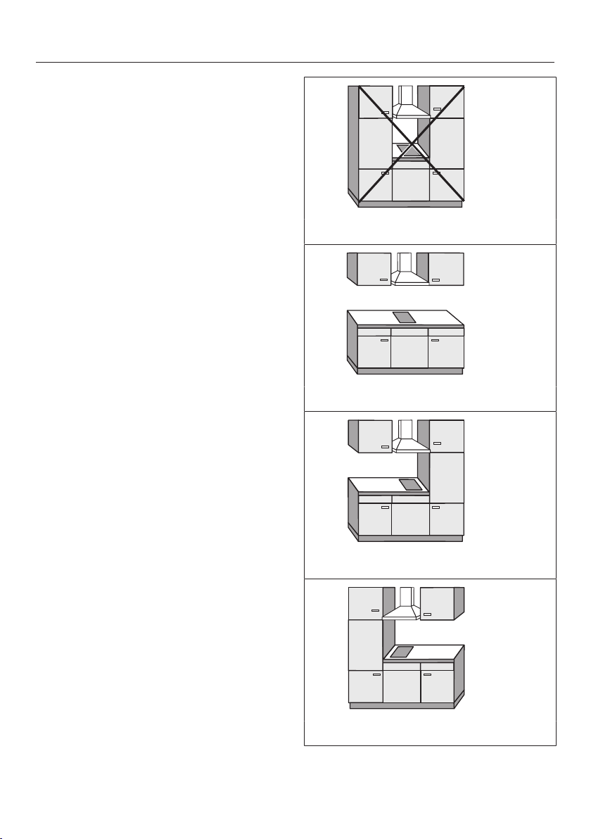
A gas appliance shall be installed such
that the surface temperature of any
nearby combustible surface* will not
exceed 65°C above ambient.
The minimum clearance from a
combustible surface shall be a 200mm
horizontal distance from the periphery
of any gas burner (AS/NZS 5601.1).
If that horizontal clearance is less than
200mm, that vertical surface must be
protected by a non-combustible
material for 150mm above the top of
the edge of the nearest burner for the
full dimension of the cooktop (depth,
width).
X Height from worktop surface to the
top of the edge of the burner
The shown area indicates the protected
surface, which may be ceramic tiles or
other approved material.
*Combustible surface:
A material which will ignite and burn,
and includes material which has been
flameproofed.
Installation
*INSTALLATION*
39
Detailed dimensions
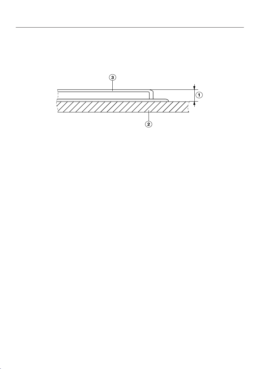
Height of pan supports above the worktop surface
a
Vertical distance
b
Worktop surface
c
Pan support
The vertical distance from the top of the pan supports to the surface of the
worktop is 37mm.
Installation
*INSTALLATION*
40
Surface-mounted
Installation notes –
surface-mounted
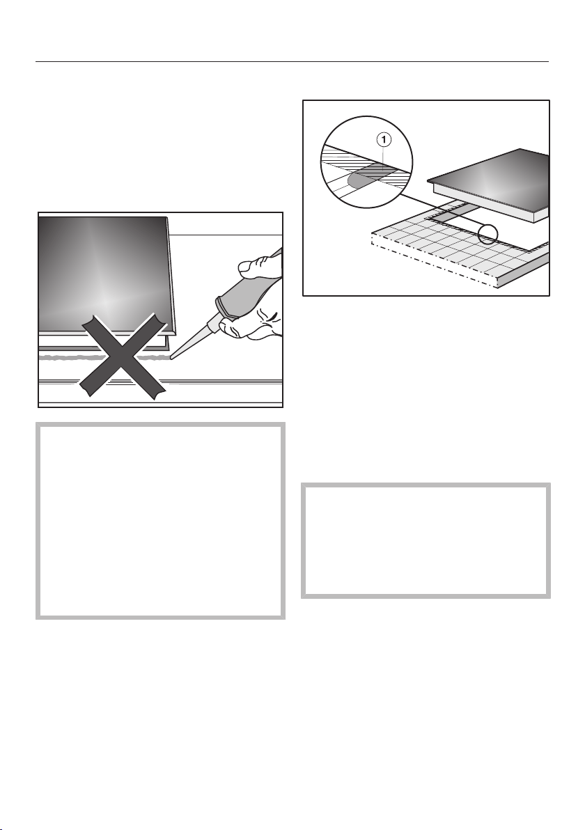
Sealing between the SmartLine
appliance and the worktop
The SmartLine appliance and
worktop may be damaged if the
appliance needs to be removed after
it has been sealed with a sealant.
Do not use any sealant between the
SmartLine appliance and the
worktop.
The sealing strip under the edge of
the top part of the appliance
provides a sufficient seal for the
worktop.
Tiled worktop
Grout lines and the hatched area
underneath the SmartLine appliance
frame must be smooth and even. If they
are not, the SmartLine appliance will
not sit flush with the worktop and the
sealing strip underneath the top part of
the appliance will not provide a good
seal between the appliance and the
worktop.
Sealing strip
Dismantling the SmartLine appliance
for service purposes may damage
the sealing strip underneath the edge
of the SmartLine appliance.
Always replace the sealing strip
before reinstalling the cooktop.

Installation
*INSTALLATION*
41
Installing several
SmartLine appliances
The gaps between the individual
SmartLine appliances must be sealed
with a silicone sealant that is heat-
resistant to at least 160°C. With flush-
fit installation, the gap between the
SmartLine appliance(s) and the worktop
must also be sealed with a silicone
sealant that is heat-resistant to at least
160°C.
After installation, the SmartLine
appliances must be easily accessible
from below, so that the bottom half of
the casing can be removed for
maintenance. If the SmartLine
appliances are not accessible from
below, the sealant must be removed so
that they can be removed.
Combination with a downdraft
extractor
If the SmartLine appliance is installed in
combination with a downdraft extractor,
the latter must be installed first.
Installation
*INSTALLATION*
42
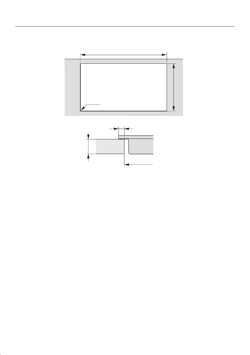
Worktop cut-out – surface-mounted
B
500
+1
ß
R 4
B
10
0
10
Information for calculating the cut-out
The appliances overlap the worktop by 10mm.
When installing several appliances, a distance of 2mm must be observed between
the individual appliances.
Calculating cut-out dimensionB
1 appliance = width of the appliance minus 10mm on the right, minus 10mm on
the left
Several appliances = total width of the appliances plus 2mm distance between
the appliances, minus 10mm on the right, minus 10mm on the left.
Some examples are illustrated below.
Installation
*INSTALLATION*
43
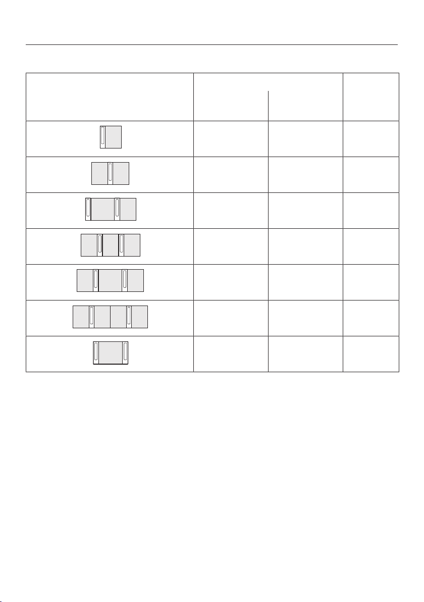
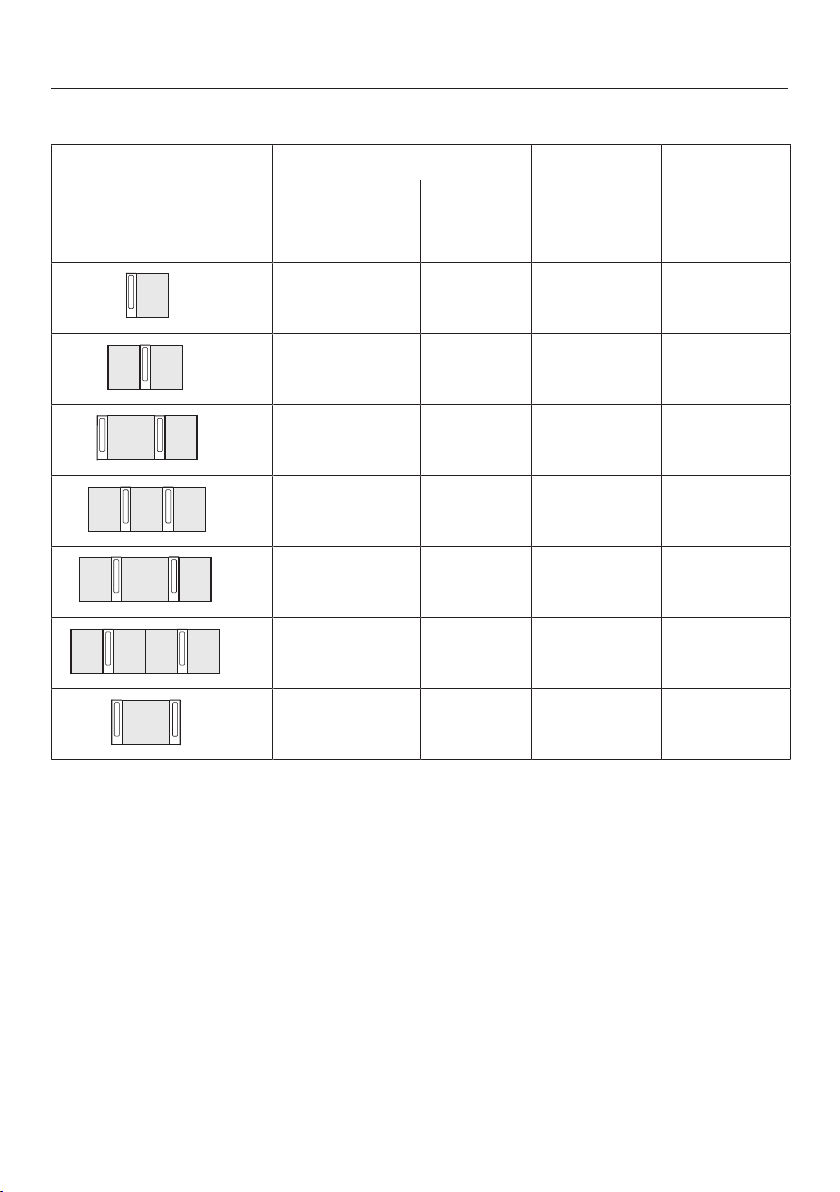
Installation with a downdraft extractor
Sample combinations Numberxwidth [mm] Dimension
B
[mm]
Cooking
appliances
Downdraft
extractor
1 x 378 1 x 120
480
+1
2 x 378 1 x 120
860
+1
1x378
1x620
2 x 120
1224
+1
3 x 378 2 x 120
1362
+1
2x378
1x620
2 x 120
1604
+1
4 x 378 2 x 120
1742
+1
1 x 620 2 x 120
844
+1
Installation
*INSTALLATION*
44
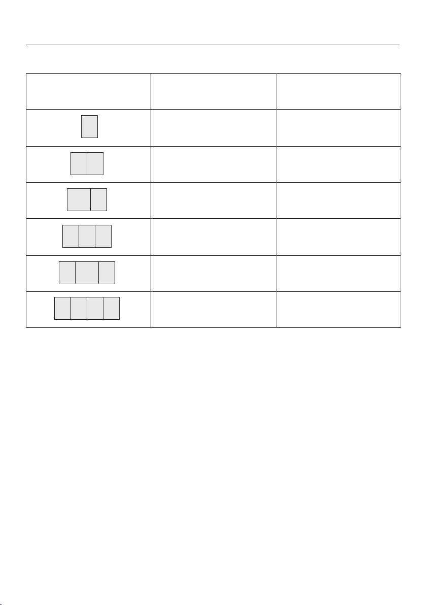
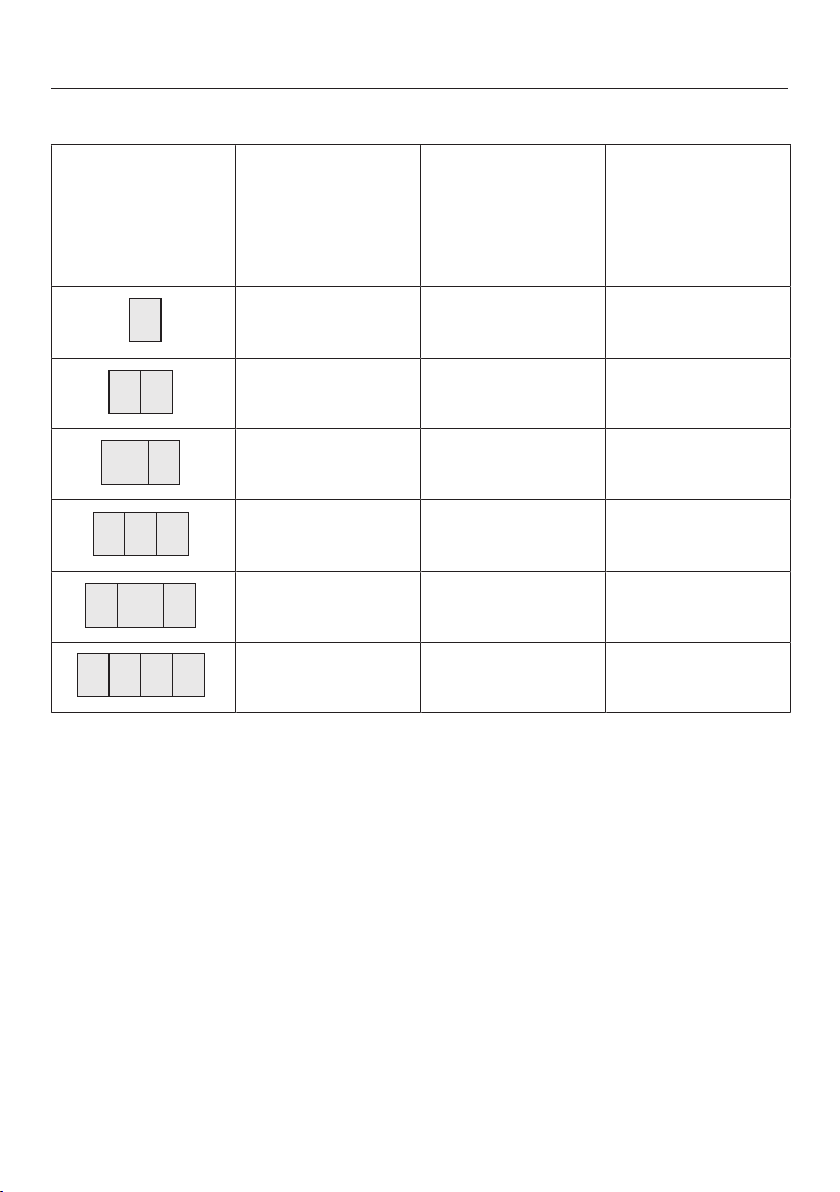
Installation without a downdraft extractor
Sample combinations Numberxwidth [mm] DimensionB
[mm]
Cooking appliances
1 x 378
358
+1
2 x 378
738
+1
1x378
1x620
980
+1
3 x 378
1118
+1
2x378
1x620
1360
+1
4 x 378
1498
+1
Installation
*INSTALLATION*
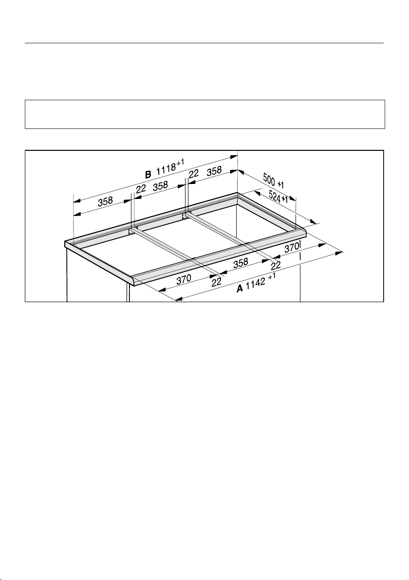
45
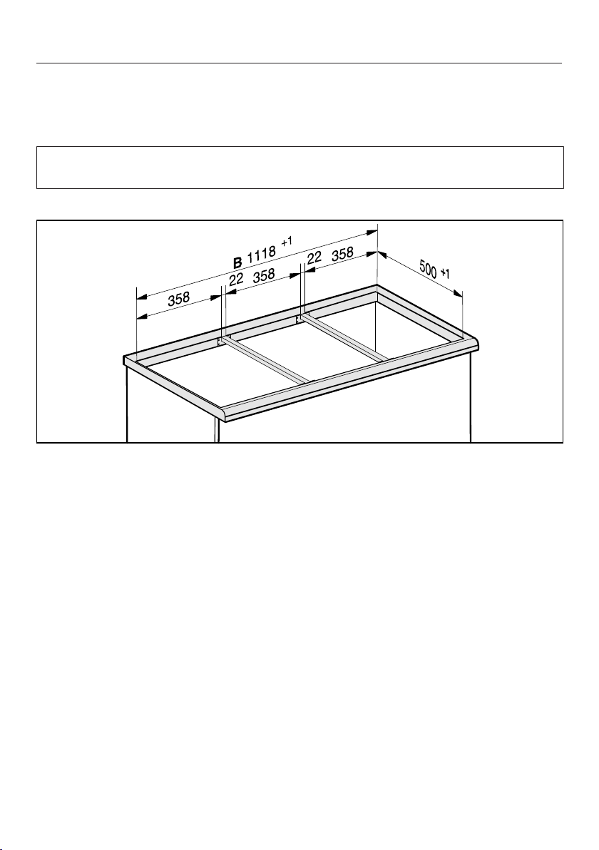
Spacer bars – surface-mounted
When installing several SmartLine appliances, an additional spacer bar must be
fitted in between the individual appliances.
The clips supplied with the spacer bars are only required for installing a
CSDA700xFL.
Installing 3 appliances and 2 spacer bars
Installation
*INSTALLATION*
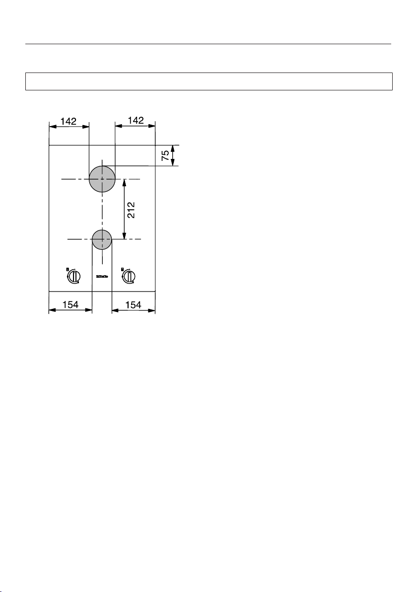
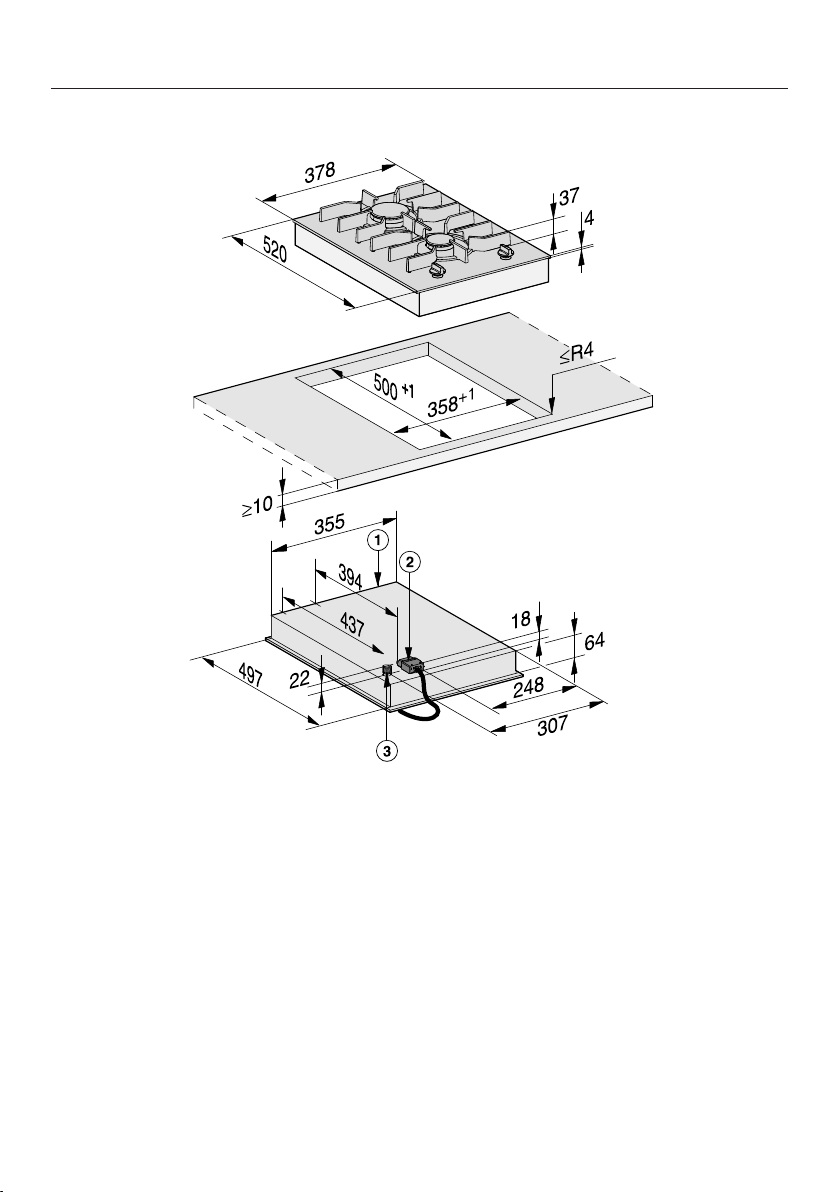
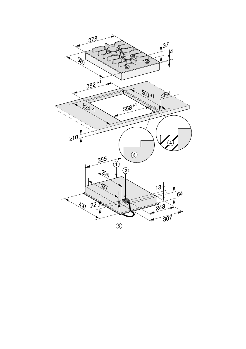
46
Installation dimensions– Surface-mounted
All dimensions in this instruction booklet are given in mm.
Distances from burner to the edge of the appliance
Installation
*INSTALLATION*
47
a
Front
b
Mains connection box with mains connection cable, L=2000mm
c
Gas connection R½ ISO 7-1 (DINEN10226)
Installation
*INSTALLATION*
48
Installation – surface-mounted
Preparing the worktop
Create the worktop cut-out.
Remember to maintain the minimum
safety distances (see "Installation –
Safety distances").
Seal the cut surfaces of wooden
worktops with a suitable sealant to
avoid swelling caused by moisture.
The sealant must be heat-resistant.
Make sure the sealant does not
come into contact with the top
surface of the worktop.
Fitting the spacer bars
Use the middle screw holes if one of the
following SmartLine appliances is
installed to the right or left of the spacer
bar: CS7611, CS 7641, CS7101(-1),
CS7102(-1)
Wooden worktops
Position the spacer bars flush onto
the upper edge of the cut-out.
Secure the spacer bars with the
3.5x25mm wood screws supplied.
Granite and marble worktops
You will need heavy-duty double-
sided tape (not supplied) to secure the
spacer bars.
Stick the tape along the top edge of
the worktop cut-out.
Position the spacer bars flush onto
the upper edge of the cut-out.
Press the spacer bars firmly into
place.
Installation
*INSTALLATION*
49
Installing the SmartLine appliance
Stick the supplied sealing strip under
the edge of the SmartLine appliance.
Do not apply the sealing strip under
tension.
Feed the mains connection cable
down through the worktop cut-out.
Position the SmartLine appliance in
the worktop cut-out. When doing this,
make sure that the seal of the
appliance sits flush with the worktop
on all sides. This is important to
ensure an effective seal with the
worktop.
If the seal does not meet the worktop
correctly on the corners, carefully
scribe the corner radii (≤R4) with a
jigsaw.
Do not use any additional sealant
(e.g. silicone) on the SmartLine
appliance.
Connect the SmartLine appliance to
the mains electrical supply.
If required, connect the SmartLine
appliance to the gas supply (see
“Installation – Gas connection”).
Check that the SmartLine appliance
works.
Seal the gaps between the individual
appliances with a silicone sealant that
is heat-resistant to at least 160°C.
Unsuitable sealant can damage
natural stone.
For natural stone worktops and
natural stone tiles, only use silicone
sealant that is specially formulated
for natural stone. Please follow the
manufacturer's instructions.
Checking operation
After installation, ignite all burners to
check that they are operating
correctly:
– The flame must not go out on the
lowest setting, or when the control is
turned quickly from the highest to the
lowest setting.
– On the highest setting, the flame
must have a distinctive and visible
core.
Installation
*INSTALLATION*
50
Flush-fit
Installation notes –
flush-fit
Flush-fit installation is only possible in
natural stone (granite, marble), solid
wood and tiled worktops. For
installation in worktops made of other
materials, please consult the relevant
manufacturer as to whether their
worktops are suitable for flush-fit
installation.
The internal width of the base unit
underneath the appliance must be at
least as wide as the inner worktop cut-
out (see “Installation – Installation
dimensions – Flush”), so that the
SmartLine appliance is easily
accessible from underneath after
installation and the bottom half of the
casing can be removed for
maintenance. If the appliance is not
freely accessible from below after
installation, the sealant must be
removed so that the appliance can be
removed.
Natural stone worktops
The SmartLine appliance is set directly
in the cut-out.
Solid wood worktops, tiled worktops,
glass worktops
The SmartLine appliance is set on a
wooden frame inside the cut-out. The
frame must be provided on site and is
not supplied with the appliance.
Sealing strip
Dismantling the SmartLine appliance
for service purposes may damage
the sealing strip underneath the edge
of the SmartLine appliance.
Always replace the sealing strip
before reinstalling the cooktop.

Installation
*INSTALLATION*
51
Installing several
SmartLine appliances
The gaps between the individual
SmartLine appliances must be sealed
with a silicone sealant that is heat-
resistant to at least 160°C. With flush-
fit installation, the gap between the
SmartLine appliance(s) and the worktop
must also be sealed with a silicone
sealant that is heat-resistant to at least
160°C.
After installation, the SmartLine
appliances must be easily accessible
from below, so that the bottom half of
the casing can be removed for
maintenance. If the SmartLine
appliances are not accessible from
below, the sealant must be removed so
that they can be removed.
Combination with a downdraft
extractor
If the SmartLine appliance is installed in
combination with a downdraft extractor,
the latter must be installed first.
Installation
*INSTALLATION*
52
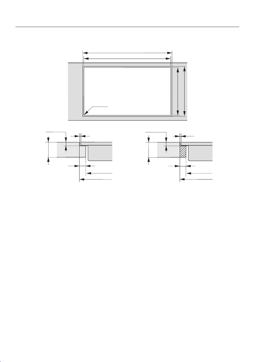
Worktop cut-out – flush-fit
B
A
524
500
+
1
+1
ß R 4
B
A
0 2
12
0
10
5,5
+
0,5 *
0 2
B
A
12
0
10
5,5
+
0,5 *
Natural stone worktop Wooden worktop
* 7
+
0.5
mm with CS7611FL
Information for calculating the cut-out
The appliances overlap the stepped cut-out by 10mm.
When installing several appliances, a distance of 2mm must be observed between
the individual appliances.
Calculating cut-out dimensionA
1 appliance = width of the appliance plus 2mm on the right, plus 2mm on the left.
Several appliances = total width of the appliances plus 2mm distance between
the appliances, plus 2mm on the right, plus 2mm on the left
Calculating cut-out dimensionB = cut-out dimension A minus 12mm on the right,
minus 12mm on the left.
Some examples are illustrated below.
Installation
*INSTALLATION*
53
Installation with a downdraft extractor
Sample combinations
Numberxwidth [mm]
DimensionA
[mm]
DimensionB
[mm]
Cooking
appliances
Downdraft
extractor
1 x 378 1 x 120
504
+1
480
+1
2 x 378 1 x 120
884
+1
860
+1
1x378
1x620
2 x 120
1248
+1
1224
+1
3 x 378 2 x 120
1386
+1
1362
+1
2x378
1x620
2 x 120
1628
+1
1604
+1
4 x 378 2 x 120
1766
+1
1742
+1
1 x 620 2 x 120
868
+1
844
+1
Installation
*INSTALLATION*
54
Installation without a downdraft extractor
Sample
combinations
Numberxwidth
[mm]
DimensionA
[mm]
DimensionB
[mm]
Cooking
appliances
1 x 378
382
+1
358
+1
2 x 378
762
+1
738
+1
1x378
1x620
1004
+1
980
+1
3 x 378
1142
+1
1118
+1
2x378
1x620
1384
+1
1360
+1
4 x 378
1522
+1
1498
+1
Installation
*INSTALLATION*
55
Spacer bars – flush-fit
When installing several SmartLine appliances, an additional spacer bar must be
fitted in between the individual appliances.
The clips supplied with the spacer bars are only required for installing a
CSDA700xFL.
Installing 3 appliances and 2 spacer bars

Installation
*INSTALLATION*
56
Installation dimensions–Flush
All dimensions in this instruction booklet are given in mm.
Distances from burner to the edge of the appliance
Installation
*INSTALLATION*
57
a
Front
b
Mains connection box with mains connection cable, L=2000mm
c
Stepped cut-out (for detailed illustrations, see “Installation – Worktop cut-out –
flush-fit”)
d
12mm wooden frame (not supplied, for detailed illustrations, see “Installation –
Worktop cut-out – flush-fit”)
e
Gas connection R½ ISO 7-1 (DINEN10226)
Installation
*INSTALLATION*
58
Installation – flush-fit
Preparing the worktop
Create the worktop cut-out.
Remember to maintain the minimum
safety distances (see "Installation –
Safety distances").
Seal the cut surfaces of wooden
worktops with a suitable sealant to
avoid swelling caused by moisture.
The sealant must be heat-resistant.
Make sure the sealant does not
come into contact with the top
surface of the worktop.
For wooden worktops, secure the
wooden frames 5.5mm below the
upper edge of the worktop.
For CS7611FL, the wooden frame
must be secured 7mm under the
upper edge of the worktop.
Fitting the spacer bars
Use the middle screw holes if one of the
following SmartLine appliances is
installed to the right or left of the spacer
bar: CS7611, CS 7641, CS7101(-1),
CS7102(-1)
Wooden worktops
Position the spacer bars flush onto
the lower step of the stepped cut-out.
Secure the spacer bars with the
3.5x25mm wood screws supplied.
Granite and marble worktops
You will need heavy-duty double-
sided tape (not supplied) to secure the
spacer bars.
Stick the tape onto the lower step of
the stepped cut-out.
Position the spacer bars flush onto
the lower step of the stepped cut-out.
Press the spacer bars firmly into
place.
Installation
*INSTALLATION*
59
Installing the SmartLine appliance
Stick the supplied sealing strip under
the edge of the SmartLine appliance.
Do not apply the sealing strip under
tension.
Feed the mains connection cable
down through the worktop cut-out.
Position the SmartLine appliance in
the worktop cut-out. When doing this,
make sure that the seal of the
appliance sits flush with the worktop
on all sides. This is important to
ensure an effective seal with the
worktop.
Connect the SmartLine appliance to
the mains electrical supply.
If required, connect the SmartLine
appliance to the gas supply (see
“Installation – Gas connection”).
Check that the SmartLine appliance
works.
Seal the gaps between the individual
SmartLine appliances and between
the appliances and the worktop with
a silicone sealant that is heat-
resistant to at least 160°C.
Unsuitable sealant can damage
natural stone.
For natural stone worktops and
natural stone tiles, only use silicone
sealant that is specially formulated
for natural stone. Please follow the
manufacturer's instructions.
Checking operation
After installation, ignite all burners to
check that they are operating
correctly:
– The flame must not go out on the
lowest setting, or when the control is
turned quickly from the highest to the
lowest setting.
– On the highest setting, the flame
must have a distinctive and visible
core.
Installation
*INSTALLATION*
60
Gas connection
Risk of explosion due to an
incorrect gas connection.
If the gas connection is carried out
incorrectly, it may result in gas
leakage.
Connection to the gas supply must
only be undertaken by an authorised
and registered gas installer in strict
accordance with current local and
national safety and building
regulations. The installer is
responsible for ensuring that the
appliance functions correctly when
installed.
Risk of explosion due to an
incorrect conversion.
If the conversion to another type of
gas is carried out incorrectly, it may
result in gas leakage.
Conversion from one type of gas to
another must only be undertaken by
an approved and registered gas
installer in strict accordance with
current local and national safety and
building regulations. The installer is
responsible for ensuring that the
appliance functions correctly when
installed.
The gas connection must be
installed so that connection can be
made either from inside or outside
the kitchen furniture unit. Every
appliance must have its own
isolating valve. The isolating valve
must be easily accessible and visible
(by opening the cabinet door if
necessary).
Check with your local gas supplier
about the type of gas supplied and
compare this information with the
type of gas quoted on the
appliance's data plate.
The cooktop is not connected to an
exhaust flue.
When installing and connecting the
appliance, please observe the
relevant regulations and ensure it has
adequate ventilation once installed.
The gas connection must be made in
accordance with national and local
regulations.
Special provisions of the local gas
supplier as well as building
regulations must also be observed.
Risk of heat damage.
Gas connections, gas hoses or pipes
and mains connection cables can be
damaged if exposed to heat from the
cooktop.
After installation make sure that
neither the gas hose/pipe nor the
mains cable can come into contact
with hot parts of the appliance and
that the gas hose/pipe and
connections on the cooktop cannot
come into contact with hot exhaust
fumes.
Installation
*INSTALLATION*
61
Risk of explosion due to
damaged gas hoses and pipes.
Gas can leak from damaged flexible
gas hoses.
Attach flexible gas hoses in such a
way that the hose assembly is not
exposed to high temperatures
exceeding the maximum
recommended by the hose
manufacturer, subjected to strain,
kinking, permanent deformation or
damage by vermin.
Connect the cooktop to the gas
supply in accordance with national
and local regulations. Check the gas
connection for any leaks.
The gas pressure must be set by an
approved gas fitter and a full
operational test and a test for
possible leakages must be carried
out by the gas fitter after installation.
Depending on country of destination,
this appliance is set up for connection
to natural gas or ULPG. See adhesive
label on the appliance:
– G = NG (natural gas)
– LP = ULPG (Propane/Butane)
Depending on country of destination,
jets are supplied for conversion to a
different type of gas. If the appropriate
jets have not been supplied with the
appliance, you will need to contact
Miele. Conversion to another type of
gas is described in the section
“Conversion to another type of gas”.
Connecting the cooktop
The cooktop is supplied with a ¹/₂"
threaded gas connection. There are two
connection options:
– Fixed connection.
– Flexible hose class B or D which
complies with AS/NZS1869 and
must be certified. The minimum inner
diameter(Ø) must be 10mm and the
maximum length 1200mm.
Risk of explosion due to gas
leakage.
Unsuitable sealant will not ensure the
required leak protection for
connections.
Ensure that a suitable sealant is
used.
Installation
*INSTALLATION*
62
Setting the gas pressure
The gas pressure must be set by the
authorised gas fitter as shown on the
data plate:
Natural gas 1.0 kPa
ULPG (Propane/Butane) 2.75 kPa
The gas pressure must be set with the
largest burner operating at maximum
setting.
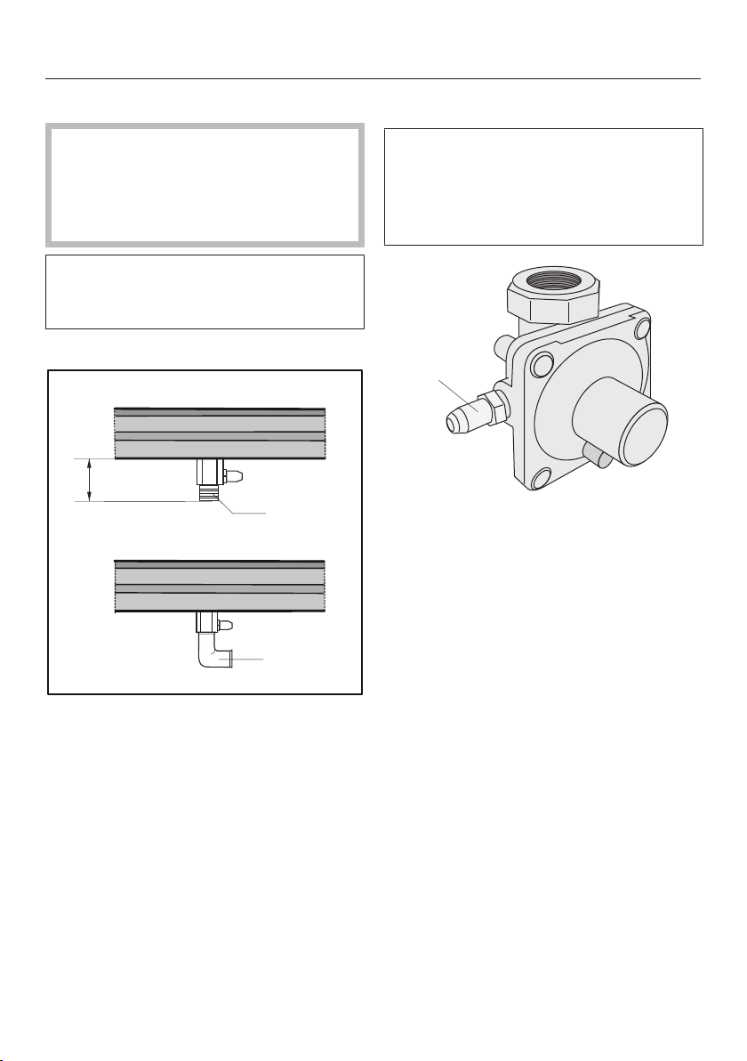
For ULPG models
a
b
~ 60
a
Connection R¹/₂" with test point
b
Connection R¹/₂" with test point and
90° angle
When using a 90° angle the building-
in depth will increase to the depth of
the elbow used.
For natural gas models
The gas regulator is only included with
appliances which are set up for
connection to natural gas. The
regulator must be connected directly
to the appliance.
a
a
Pressure Test Point
Loosen the screw in the test point
until it is free in its housing. The
screw is retained in this position.
Connect the hose from the pressure
gauge.
Reassemble one of the large burners,
turn on the gas and manually light the
burners.
Disconnect the hose from the
pressure gauge and screw in the test
point screw.
For natural gas models: Connect the
gas regulator directly to the
appliance.
Installation
*INSTALLATION*
63
Electrical connection
We recommend that you connect the
SmartLine appliance to the mains via a
suitable switched electrical socket. This
simplifies servicing. The socket must be
easily accessible after the SmartLine
appliance has been installed.
Danger of injury!
Installation, repairs and other work
by unqualified persons could be
dangerous. Miele cannot be held
liable for unauthorised work.
Miele cannot be held liable for
damage or injury (e.g. electric shock)
caused by the lack of or inadequacy
of an on-site earthing system.
If the plug is removed from the
connection cable or if the cable is
supplied without a plug, the
SmartLine appliance must be
connected to the electricity supply
by a suitably qualified electrician.
If the socket is no longer accessible,
or if a hard-wired connection is
planned, an additional means of
disconnection must be provided for
all poles in accordance with the
wiring rules. Suitable means of
disconnection include switches with
an all-pole contact gap of at least
3mm. These include miniature circuit
breakers, fuses and relays. The
connection data can be found on the
data plate. Please ensure this
information matches the household
mains electricity supply.
After installation, ensure that all
electrical components are shielded
and cannot be accessed by users.
Total power output
See data plate.
Connection data
The connection data is given on the
data plate. Please ensure this
information matches the household
mains supply.
Residual current device
For extra safety, it is advisable to
protect the SmartLine appliance with a
suitable residual current device (RCD)
with a trip range of 30mA.
WARNING
THIS APPLIANCE MUST BE
EARTHED
Replacing the mains connection
cable
Danger of electric shock!
Incorrect connection to the electricity
supply may result in an electric
shock.
The mains connection cable must
only be replaced in accordance with
current local and national safety
regulations.
When replacing the mains connection
cable, it must be replaced with cable
type H05VV-F by a Miele authorised
service technician or a suitably qualified
and competent electrician in order to
avoid a hazard. These cables are
available from Miele.
Burner ratings
64
Nominal ratings
Burner Gas type Highest setting Lowest setting
MJ/h MJ/h
Semi-rapid burner Natural gas 6.0 1.2
ULPG 5.7 0.9
Rapid burner Natural gas 9.7 1.6
ULPG 8.6 1.9
Total Natural gas 15.7 –
ULPG 14.3 –
Conversion to another type of gas
*INSTALLATION*
65
Risk of explosion due to an
incorrect conversion.
If the conversion to another type of
gas is carried out incorrectly, it may
result in gas leakage.
Conversion from one type of gas to
another must only be undertaken by
an authorised and registered gas
installer in strict accordance with
current local and national safety and
building regulations. The installer is
responsible for ensuring that the
appliance functions correctly when
installed. Disconnect the cooktop
from the electricity supply and turn
off the gas supply.
Jet table
The jet markings refer to a ¹/₁₀₀mm
bore diameter.
Main jet Small jet
Natural gas
Semi-rapid
burner
1.10 0.52
Rapid burner 1.43 0.60
ULPG
Semi-rapid
burner
0.66 0.27
Rapid burner 0.81 0.39
Changing the jets
Disconnect the cooktop from the
electricity supply and turn off the gas
supply.
When converting to another type of
gas, both the main and small jets
need to be changed.
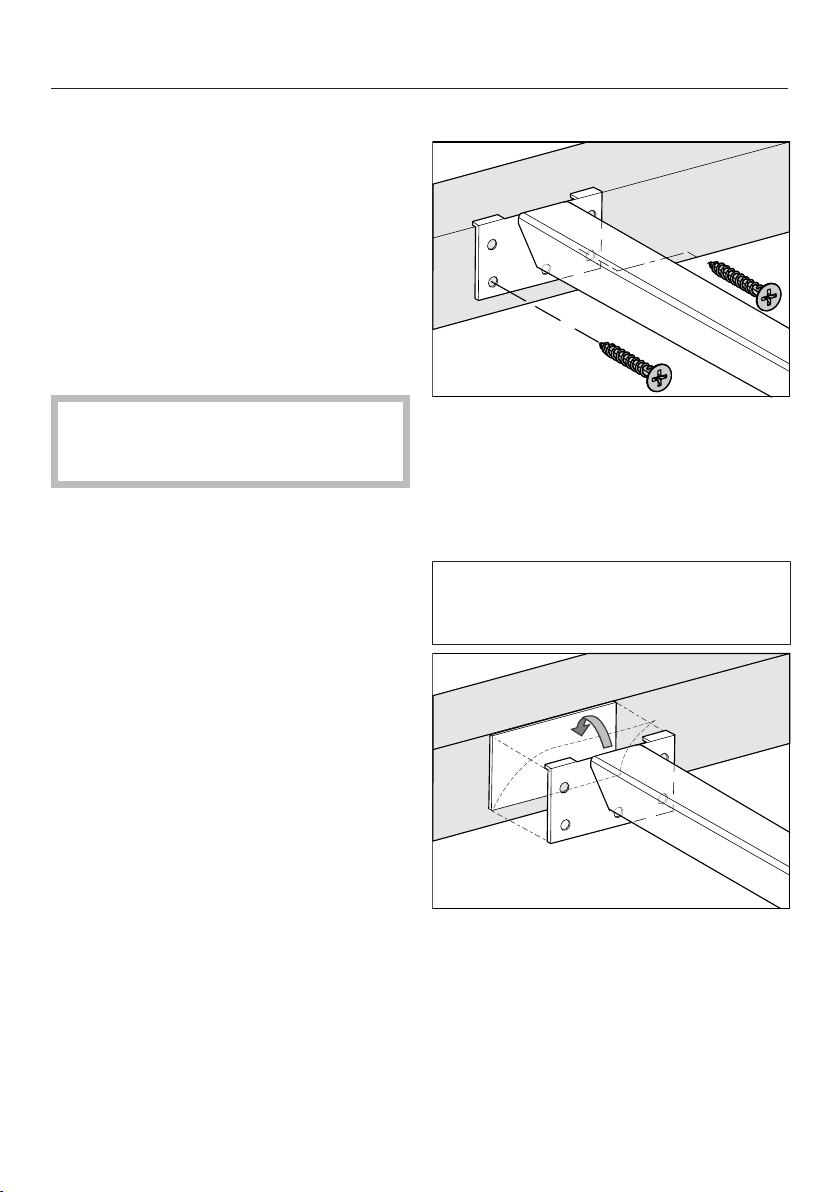
Changing the main jets
Remove the pan support, burner
cap and burner head.
Using an M7 socket spanner,
unscrew the main jet.
Fit the correct jets securely (see jet
table).
Secure the jets against inadvertent
loosening with sealing wax.
Conversion to another type of gas
*INSTALLATION*
66
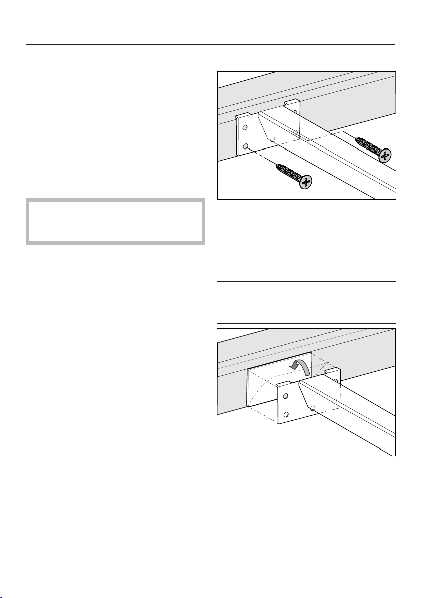
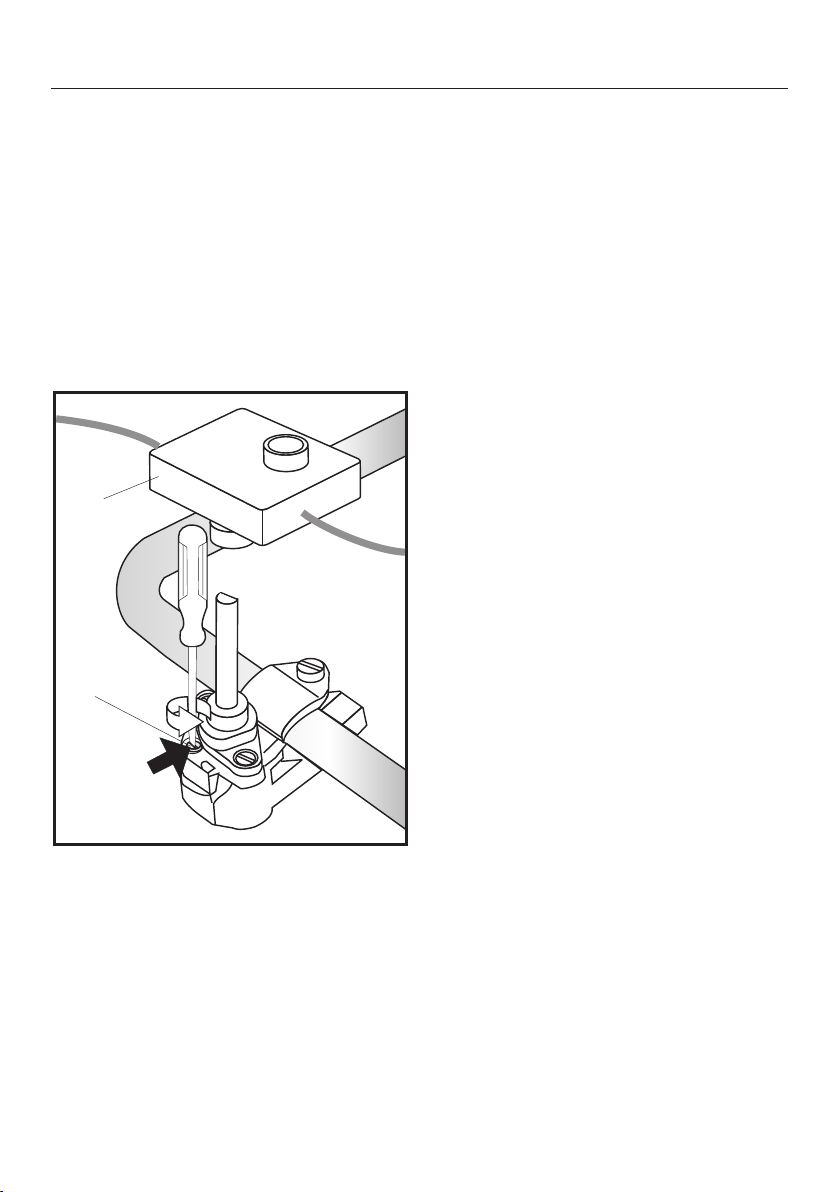
Changing the small jets
Remove the burner components.
Loosen the fixing screws on the
burners.
Pull the control knobs off.
Loosen the fixing nuts on the
underside of the appliance.
Carefully remove the underside of the
appliance.
a
b
Remove the ignition switch.
Using a small screwdriver, unscrew
the small jet in the gas fitting.
Pull out the jet with a pair of pliers.
Fit the correct jets securely (see jet
table).
Secure the jets against inadvertent
loosening with sealing wax.
Checking operation
Check all gas fittings for leaks.
Reassemble the cooktop.
Ignite all burners to check that they
are operating correctly.
– The flame must not go out on the
lowest setting, or when the control is
turned quickly from the highest to the
lowest setting.
– On the highest setting, the flame
must have a distinctive and visible
core.
Adhere the label supplied with the
jets over the old label stating the type
of gas being used.

Miele Experience Centre and
Head Office Melbourne:
1 Gilbert Park Drive
Knoxfield, VIC 3180
Miele Experience Centre South Melbourne:
206-210 Coventry Street
South Melbourne, VIC 3205
Miele Experience Centre and Office Sydney:
3 Skyline Place
Frenchs Forest, NSW 2086
Miele Experience Centre and Office Brisbane:
Tenancy 4C, 63 Skyring Terrace
Newstead, QLD 4006
Miele Experience Centre and Office Perth:
83-85 Sir Donald Bradman Drive
Hilton, SA 5033
Miele Experience Centre and Office Adelaide:
Miele Australia Pty. Ltd. Miele New Zealand Limited
Level 2, 10 College Hill
Freemans Bay, Auckland 1011
Miele Experience Centre
Auckland:
8 College Hill
Freemans Bay, Auckland 1011
Miele Global Headquarters
Germany
Miele & Cie. KG
Carl-Miele-Straße 29
33332 Gütersloh
Federal Republic of Germany
Head Office:
IRD 98 463 631
ACN 005 635 398
ABN 96 005 635 398
Miele Experience Centre Gold Coast:
131 Ferry Road
Southport, QLD 4215
Miele Experience Centre
Wellington:
183 Featherston Street
Wellington 6011
0800 464 353 (0800 4 MIELE)
www.miele.co.nz
205-207 Stirling Highway
Claremont, WA 6010
1300 464 353 (1300 4 MIELE)
www.miele.com.au

M.-Nr. 11 503 520 / 00en-AU, NZ
CS7102-1