Installation Instalación
ィマ・ホォeェキNィニカオ
•・サセサウ。ェコ4ュモ、p、ユスミ、ナセユヲロトイーハ。A・ヲュフカネィムコラァ゙ウN、Hュユセ羶ユソモ
セケ、ァ・ホ。C
•・サセミゥb、」ァォテェ・qセrセp、ァウB。C
•チラァKアN・サセbーェキナ、ァウB。Aヲpカァ・スアオキモョg。Bキxョe。Bゥホヲヌケミキ・ヲh。B
ナシカテ。A・H、ホキ・ゥーハオ・ヲa、陦C
•ャー、Fヲw・™ーィ」。Aヲwクヒョノスミィマ・ホェ™ーeェコウ。・ C
ヲwクヒィ、ォラ、ァスユセ
スミヲb60ォラ・H、コスユセ罔wクヒィ、ォラ。C
Precauciones
•No toque los cuatro orificios de la superficie superior de la unidad.
Estos orificios son para ajustes del sintonizador que solamente
deberán realizar técnicos de reparación.
•Elija cuidadosamente el lugar de montaje de forma que la unidad
no interfiera las funciones normales de conducción.
•Evite instalar la unidad donde pueda quedar sometida a altas
temperaturas, como a la luz solar directa o al aire de calefacción, o a
polvo, suciedad, o vibraciones excesivas.
•Para realizar una instalación segura y firme, utilice solamente la
ferretería de montaje suministrada.
Ajuste del ángulo de montaje
Ajuste el ángulo de montaje a menos de 60°.
ヲwクヒ
Precautions
•Do not tamper with the four holes on the upper surface of the unit.
They are for tuner adjustments to be done only by service
technicians.
•Choose the installation location carefully so that the unit will not
hamper the driver during driving.
•Avoid installing the unit where it would be subject to high
temperatures, such as from direct sunlight or hot air from the
heater, or where it would be subject to dust, dirt or excessive
vibration.
•Use only the supplied mounting hardware for a safe and secure
installation.
Mounting angle adjustment
Adjust the mounting angle to less than 60°.
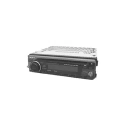
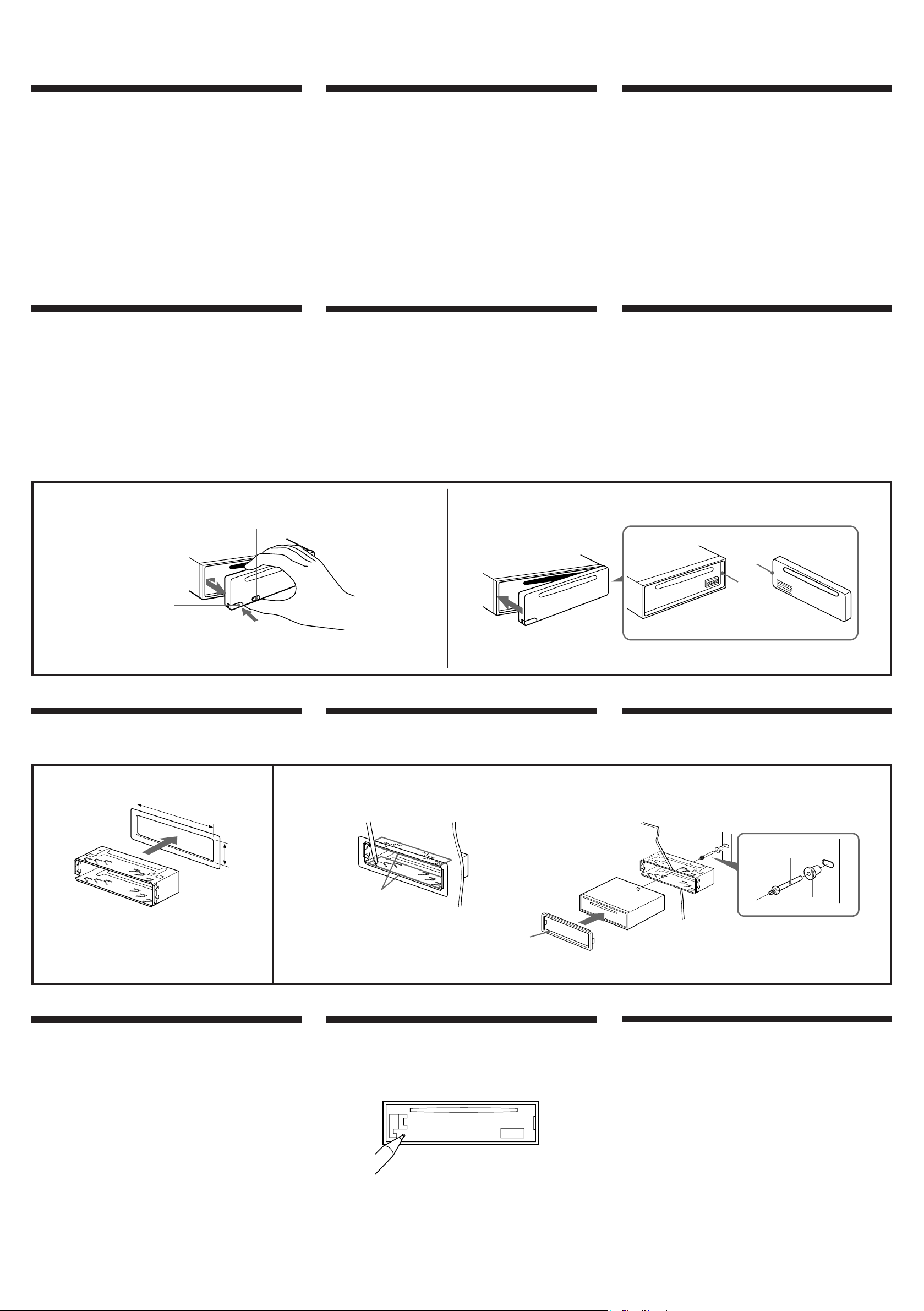
How to detach and attach the front panel
Before installing the unit, detach the front panel.
A To detach
Before detaching the front panel, be sure to press (OFF) to turn off
the unit. Then press (RELEASE), slide the front panel a little to the
left, and pull it off toward you.
B To attach
Align the parts A and B, and push the front panel until it clicks.
A
3
To support the unit
Sujeción de la unidad
ュn、莨オ・サセ
1 2
Bend these claws, if necessary.
Si es necesario, doble estas uñas.
ュYヲウ・イュn。Aォh・iナsヲアウoィヌ・d、C
Mounting example
Installation in the dashboard
Ejemplo de montaje
Instalación en el salpicadero
ヲwクヒ・ワィメ
ヲbサΜO、、ヲwクヒ
Dashboard
Salpicadero
サΜO
Fire wall
Panel cortafuegos
ィセ、タ
First attach 5 to the unit, then insert the unit into 1.
En primer lugar, fije 5 a la unidad y, a conginuación, inserte ésta en 1.
ュコ・©スミアN 5クヒィぇサセW。AオMォ盂N・サセ。、J1。C
2
13
5
TOP
Reset button
When the installation and connections are complete, be sure to press
the reset button with a ballpoint pen etc.
Botón de reposición
Cuando finalice la instalación y las conexiones, cerciórese de
presionar el botón de reposición con un bolígrafo, etc.
エヲっ
キΘwクヒゥMウsアオァケヲィォ癸Aーネスミ・ホカ]オァオ・ォ」エヲっ茖C
B
Forma de extraer e instalar el panel frontal
Antes de instalar la unidad, extraiga el panel frontal.
A Para extraerlo
Antes de extraer el panel frontal, cerciórese de presionar (OFF) para
desactivar la unidad. Después, presione (RELEASE), desplase
ligeramente el panel frontal hacia la izquierda y tire de él hacia
usted.
B Para instalarlo
Alinee las partes A y B, y presione el panel frontal hasta que
chasquee.
ヲpヲMクヒーtォeェO
ヲwクヒ・サセァォe。Aスミ・©ゥeェO。C
Aゥ
ゥeェO、ァォe。Aーネ・イ・©ォ U(OFF)チ茖A・Hテャ・サセCオMォ癸AォU
(RELEASE)チ茖AアNォeェOオyキLヲV・ェテ莵ニーハ。Aィテ・BアN・ヲエツォe、隧ヤ・X。C
Bクヒーt
スミアNAウBゥMBウBケヌ。AオMォ盂タ、JォeェO。Aェスヲワナ・ィぇdワヨ、@チn。C
1
With the TOP marking up.
Con la marca TOP hacia arriba.
ュnィマアaTOPシミーOュアエツ、W。C
182 mm
53 mm
TOP
A
(OFF)
(RELEASE)
B
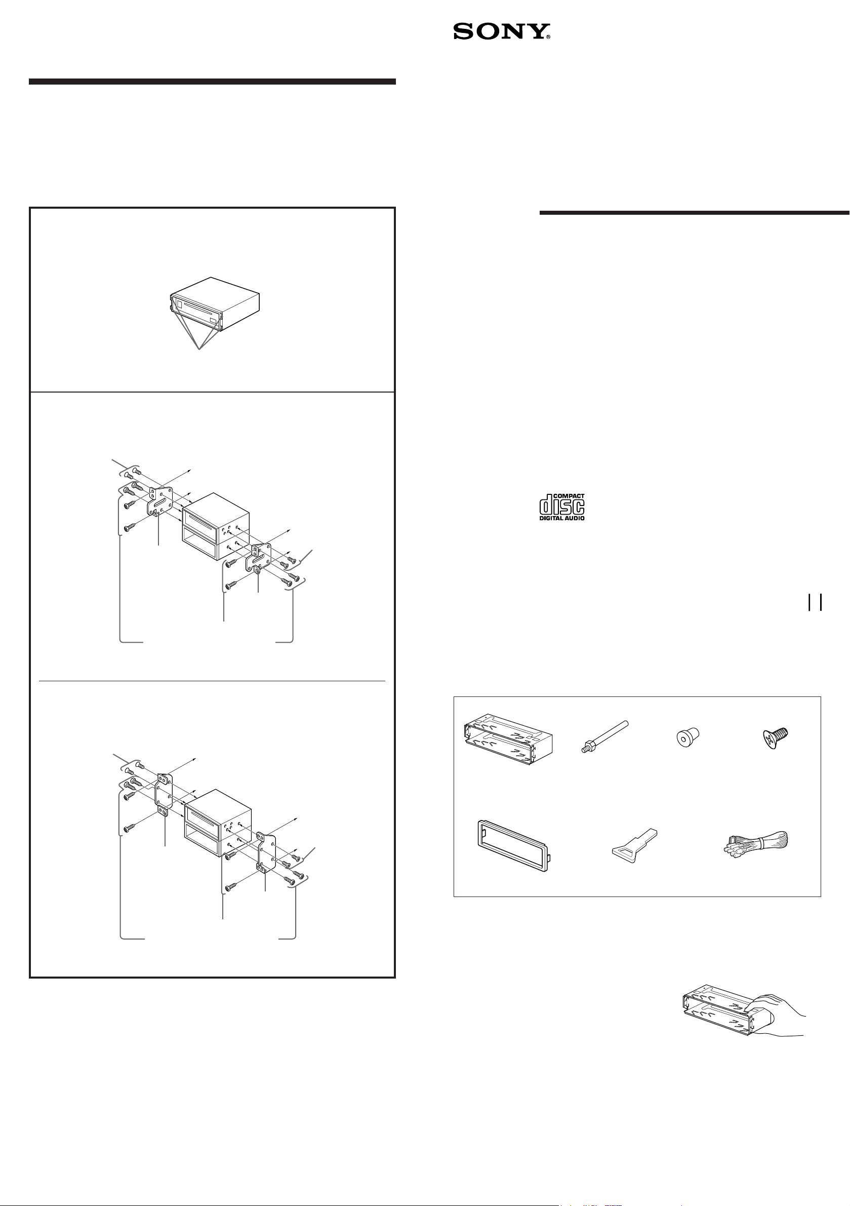
Mounting the unit in a Japanese car
Montaje de la unidad en un automóvil japonés
アN・サセwクヒゥ鬣サイ」ィTィョクフ
You may not be able to install this unit in some makes of Japanese cars. In such a case, consult your
Sony dealer.
Usted no podrá instalar esta unidad en algunos automóviles japoneses. En tal caso, consulte a su
proveedor Sony.
ヲウェコ、鬣サイ」ィTィョ、」ッ爬wクヒ・サセAヲbウoコリア。ァホ、U。AスミアzヲVキΘaェコSonyクgセPーモソヤク゚。C
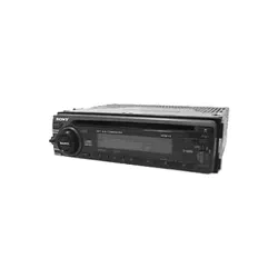
FM/AM
Compact Disc
Player
Installation/Connections
Instalación/Conexiones
ヲwクヒ。™スuクsアオ
Sony Corporation 1998
CDX-4480ESP
Parts for installation and connections
Componentes de montaje y conexiones
ヲwクヒ、ホスuクsアオ・ホウ。・
The numbers in the list are keyed to those in the instructions.
Los números de la lista corresponden a los de las instrucciones.
、UュアケマェフェコシニヲrサPサ。ゥム、、ェコシニヲrャO、@ュPェコ。C
1
The release key 6 is used for dismounting the unit. See the operating instructions manual for details.
La llave de liberación 6 se utiliza para desmontar la unidad. Con respecto a los detalles, consulte el
manual de instrucciones.
トタゥ6・ホゥサセCヲウテヤイモア。ェp。Aスミームィ」ィマ・ホサ。ゥム。C
Caution
Cautionary notice for handling the bracket 1.
Handle the bracket carefully to avoid injuring your fingers.
Precaución
Advertencia sobre la manipulación del soporte 1.
Tenga mucho cuidado al manipular el soporte para evitar
posibles lesiones en los dedos.
ァiサ¦
テBクmヲォャ[1ェコェキNィニカオ。C
ュn、p、゚ウBクmヲォャ[。A・HァKカヒョ、筬C
1
Claws
Ganchos
・d、
2
TOYOTA
NISSAN
Note
To prevent malfunction, install only with the supplied screws 4.
Nota
Para evitar que se produzcan fallos, realice la instalación solamente con los tornillos suministrados 4.
オ
ャーィセ、o・ヘャGサル。Aヲwクヒョノ・uッ爲マ・ホェ™ーeェコチウオキ
4
。C
2
3
4
5
67
TOP
TOP
Bracket
Soporte
ヲォャ[
Existing parts supplied to your car
Piezas existentes suministradas con su
automóvil
タHィTィョェ™ーeェコウ。・
Bracket
Soporte
ヲォャ[
Bracket
Soporte
ヲォャ[
Existing parts supplied to your car
Piezas existentes suministradas con su
automóvil
タHィTィョェ™ーeェコウ。・
4
max. size
5 × 8 mm
Tamaño máx.
5 × 8mm
ウフ、j、リ、o
5。ム8mm
4
max. size
5 × 8 mm
Tamaño máx.
5 × 8mm
ウフ、j、リ、o
5。ム8mm
to dashboard/center console
al salpicadero/consola central
ヲワサΜO。™、、・。アアィ c
to dashboard/center console
al salpicadero/consola central
ヲワサΜO。™、、・。アアィ c
3-862-043-21 (1)
Bracket
Soporte
ヲォャ[
4
max. size
5 × 8 mm
Tamaño máx.
5 × 8mm
ウフ、j、リ、o
5。ム8mm
4
max. size
5 × 8 mm
Tamaño máx.
5 × 8mm
ウフ、j、リ、o
5。ム8mm
With nippers or similar, cut off the claws on both side of the unit.
Con unas tenazas o una herramienta similar, corte los ganchos de
ambos lados de la unidad.
スミィマ・ホケX、lゥホテ™ヲコ、uィ罍A、チ・h・サセ箍シ、Wェコ・d、C
× 5
(incl. 1 reserve)
(se incluyen 1 de reserva)
。]・]ャA1ュモウニ・ホェコ。^
Conexiones
Precauciones
• Esta unidad ha sido diseñada para alimentarse con 12 V CC,
negativo a masa, solamente.
• Antes de realizar las conexiones, desconecte el terminal de puesta a
masa de la batería del automóvil a fin de evitar cortocircuitos.
• Conecte los cables de entrada de alimentación amarillo y rojo
solamente después de haber conectado los demás.
• Cerciórese de conectar el cable de entrada de alimentación rojo a un
terminal de 12 V positivo que se energice al poner la llave de
encendido en la posición para accesorios.
• Conecte todos los conductores de puesta a masa a un punto
común.
•Conecte el cable amarillo a un circuito libre del automóvil que
tenga una capacidad superior a la del fusible de la unidad. Si
conecta esta unidad en serie con otros componentes estereofónicos,
el circuito del automóvil al que se encuentran conectados debe
tener una capacidad superior a la de la suma de las capacidades de
los fusibles de cada componente. Si ningún circuito del automóvil
tiene una capacidad tan alta como la del fusible de la unidad,
conecte ésta directamente a la batería. Si el automóvil no dispone
de ningún circuito para conectar esta unidad, conéctela a un
circuito del automóvil con capacidad superior a la del fusible de la
unidad, de forma que si se funde el fusible de ésta, no se
interrumpa ningún otro circuito.
スuクsアオ
ェキN
• ・サセuッ爲マ・ホュtキ・アオヲa12Vェスャyケqキス。C
• ウsアオォe。A・©ゥ゙・hィTィョケqヲタェコアオヲaコン、l。A・HァKオo・ヘオuク C
• カタヲ筰Mャ篁qキスソ鬢Jセノスu・イカキヲbゥメヲウィ茹ヲセノスuウ」ウsアオァケイヲ・Hォ皃˜ウsアオ。C
• ャ篁qキスセノスuーネスミウsアオヲワ+12Vケqキスコン、l。]クモケqキスコン、lヲbィTィョオoーハセ
ツI、ーヘウBゥイァUヲずmョノ、˜ウqケq。^。C
• アNゥメヲウヲaスuウ」ウsアオィえP、@ヲaツI。C
•アNカタヲ篝ノスuウsアオィうjゥケォOタIオキテBゥwョeカqェコ・シヲホェコィTィョケqクW。C
ュYアN・サセMィ茹ヲ・゚ナ鮹nクヒクmャロ、ャヲp。AゥメウsアオェコィTィョケqクeカq・イカキ、j
ゥUイユヲィセOタIオキョeカqェコチゥM。C
ュYィSヲウサP・サセOタIオキテBゥwョeカq、@シヒ、jェコィTィョケqクiクQ・ホ。A・iアN・サセ
ェスアオウsアオィせqヲタ、W。C
ュYオLセAキΜコィTィョケqクi・ホゥsアオ・サセAスミアN・サセsアオィうjゥサセOタI
オキョeカqェコィTィョケqクW。Cウoシヒ。AュY・サセコォOタIオキソNツ、F。A、]、」ュPゥチツ
ィ茹ヲケqクC
Connections
Caution
• This unit is designed for negative ground 12 V DC operation only.
• Before making connections, disconnect the ground terminal of the
car battery to avoid short circuits.
• Connect the yellow and red power input leads only after all other
leads have been connected.
• Be sure to connect the red power input lead to the positive 12 V
power terminal which is energized when the ignition key is in the
accessory position.
• Run all ground wires to a common ground point.
•Connect the yellow cord to a free car circuit rated higher than the
unit’s fuse rating. If you connect this unit in series with other stereo
components, the car circuit they are connected to must be rated
higher than the sum of the individual component’s fuse rating. If
there are no car circuits rated as high as the unit’s fuse rating,
connect the unit directly to the battery. If no car circuits are
available for connecting this unit, connect the unit to a car circuit
rated higher than the unit’s fuse rating in such a way that if the unit
blows its fuse, no other circuits will be cut off.
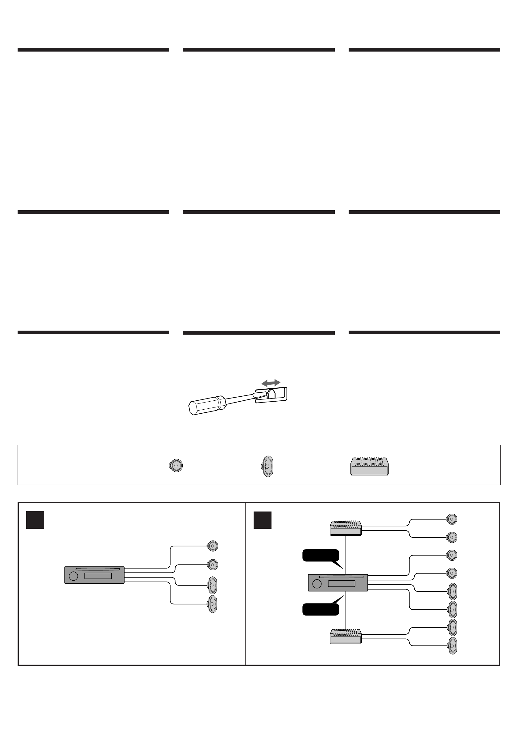
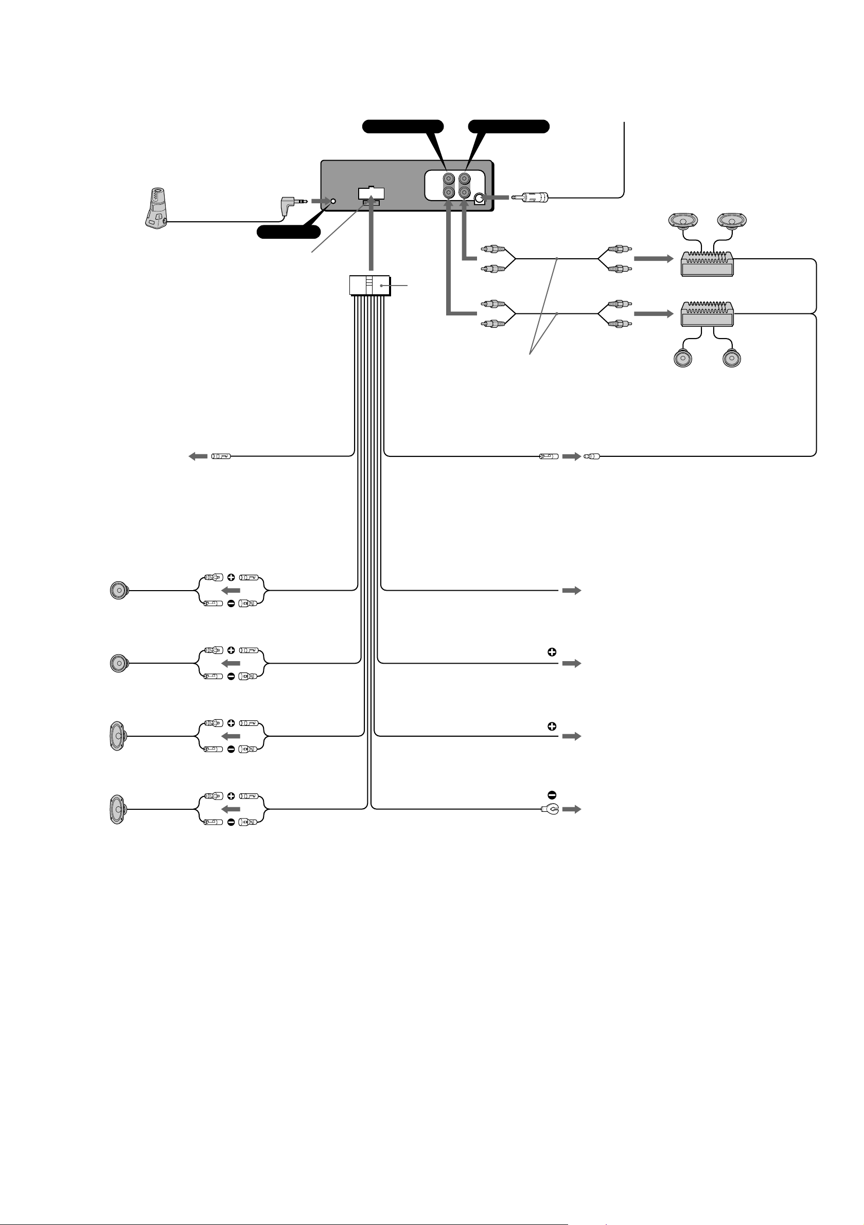
Connection diagram Diagramas de conexión スuクsアオケマ
If your car has no accessory position on the
ignition key switch — POWER SELECT switch
The illumination on the front panel is factory-set to be turned on
even when the unit is not being played. However, this setting may
cause some car battery wear if your car has no accessory position
on the ignition key switch. To avoid this battery wear, set the
POWER SELECT switch located on the bottom of the unit to the
B position, then press the reset button. The illumination is reset
to stay off while the unit is not being played.
Notes
• The caution alarm for the front panel is not activated when the POWER
SELECT switch is set to the B position.
• Do not use excessive force when changing the POWER SELECT switch.
Si el automóvil no dispone de posición para
accesorios en la llave de encendido
— Selector POWER SELECT
La iluminación del panel frontal ha sido ajustada en fábrica para que
esté activada aunque la unidad no se encuentre en reproducción. Sin
embargo, este ajuste puede provocar cierta descarga de la batería del
automóvil si éste no dispone de posición para accesorios en la
llave de encendido. Para evitar esto, ponga el selector POWER
SELECT, situado en la base de la unidad, en la posición B y,
después, presione el botón de reposición. La iluminación estará
desactivada cuando la unidad no se encuentre en reproducción.
Notas
• La alarma de precaución del panel frontal no se activará cuando el
selector POWER SELECT se encuentre en la posición B.
• No utilice excesiva fuerza al cambiar el selector POWER SELECT.
ュYアzェコィTィョヲbツI、ーヘ、WィSヲウサイァUヲずm
。XPOWERSELECTカ}テ
ォeェOェコキモゥOャO・Xシtォeウ]クmェコ。AァYィマ、」ィマ・ホ・サセノ、]キ¦オoォG。CュYュn
ヲbィTィョオoーハセI、ーヘィSィ羹イァUヲずmェコィTィョクフィマ・ホ・サセAヲケキモゥOアNキ¦
、@ェスョモキLカqェコケqヲタケq、O。Cヲ]ヲケ。Aャー、FチラァKヲbウoコリェャコA、Uェコケqヲタョモ。A
スミアN・サセウウ。ェコPOWERSELECTカ}テ]ゥwヲbB タノウB。AオMォ皚UォeェO
ェコエヲっ茖Cウoシヒ。A、」ィマ・ホ・サセノ。AキモゥOォK、」オoォG。C
オ
•
POWERSELECTカ}テQウ]ゥwヲb
B
タノョノ。AォeェOェコゼァ@ソ˜トオァi・¥ッ爿K・「ョト。C
•
ナワエォPOWERSELECTカ}テノ。A、チ、ナ・ホ、OケL、j。C
Frequency select switch
The AM (FM) tuning interval is factory-set to the 9K (50 K) position.
If the frequency allocation system of your country is based on 10 kHz
(200 kHz) interval, set the switch on the bottom of the unit to the
10 K (200 K) position before making connections.
Selector de frecuencia
El intervalo de sintonía de AM (FM) ha sido ajustado en fábrica a la
posición 9 K (50 K). Si el sistema de asignación de frecuencias de su
país se basa en el intervalo de 10 kHz (200 kHz), ponga este selector,
situado en la base de la unidad, en la posición 10 K (200 K) antes de
realizar las conexiones.
タWイvソワカ}テ
AM。]FM。^スユソモカ。ケjヲb・XシtォeウQウ]ゥwヲb9K。]50K。^ヲずm、W。CュYカQ
ーコタWイv、ターtィtイホャO・H10KHz。]200KHz。^カ。ケjャーーヲェコ。Aウsアオォe。Aスミ
アN・サセウウ。、Wェコカ}テ]ゥwヲb10K。]200K。^ヲずm、W。C
Equipment used in illustrations (not supplied)
Equipo utilizado en las ilustraciones (no suministrado)
エ。ケマ、、ィマ・ホェコクヒクm。]ォDェ™ーe。^
Front speakers
Altavoces delanteros
ォeエュチnセケ
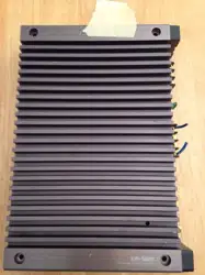
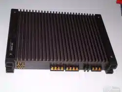
Power amplifier
Amplificador de potencia
・¥イvゥjセケ
Rear speakers
Altavoces traseros
ォ盒ュチnセケ
I
II
LINE OUT
FRONT
LINE OUT
REAR
L
R
Connection example
Ejemplo de conexiónes
スuクsアオケマィメ
Rotary commander (RM-X4S) (not supplied)
Controlador remoto gtorio (RM-X4S) (no suministrado)
アロツ爬。ササアアセケ。]RM-X4S。^。]ォDェ™ーe。^
Fuse (10 A)
Fusible (10 A)
ォOタIオキ。]10A。^
7
ATT
Sky blue
Azul celeste
、ムツナヲ
Red
Rojo
ャ
Yellow
Amarillo
カタヲ
Black
Negro
カツヲ
Purple
Púrpura
オオヲ
Green
Verde
コ
Gray
Gris
ヲヌヲ
White
Blanco
・ユヲ
to the interface cable of a car telephone
al cable de interfaz de un teléfono para automóvil
ヲワィTィョケqクワェコアオ、fケqニl
to the +12 V power terminal which is energized at all times
Be sure to connect the black earth lead to it first.
a un terminal de alimentación de +12V que esté permanentemente
energizado
Asegúrese de conectar primero a este terminal el conductor de
puesta a masa negro.
ヲワタHョノウ」ウqケqェコ+12Vケqキスコン、l
ーネスミュコ・©アNカツヲ 箜オヲaセノスuサPィ莎sアオ。C
to a metal point of the car
First connect the black earth lead, then connect the yellow and red
power input leads.
a un punto metálico del automóvil
En primer lugar conecte el conductor de puesta a tierra negro y, a
continuación, los cables de entrada de alimentación amarillo y rojo.
ヲワィTィョェコェンウ。ヲ
ュコ・©ウsアオカツヲ 箜オヲaセノスu。AオMォ皋Aウsアオカタヲ筰Mャ篁qキスソ鬢Jセノスu。C
Right
Derecho
・k
Left
Izquierdo
・ェ
Left
Izquierdo
・ェ
Right
Derecho
・k
to the +12 V power terminal which is energized in the accessory
position of the ignition key switch
Be sure to connect the black earth lead to it first.
a un terminal de alimentación de +12 V que se energice en la
posición para accesorios de la llave de encendido
Asegúrese de conectar primero a este terminal el conductor de
puesta a masa negro.
ヲワヲbツI、ーヘェコサイァUヲずm、Wウqケqェコ+12Vケqキスコン、l
ーネスミュコ・©アNカツヲ 箜オヲaセノスuサPィ莎sアオ。C
REMOTE IN
LINE OUT FRONT LINE OUT REAR
from car antenna
a la antena del automóvil
ィモヲロィTィョ、ムスu
AMP REM
Blue white striped
Azul con raya blanca
ツナ・ユアセ
Max. supply current 0.3 A
Corriente máx. de alimentación de 0,3 A
ウフ、jィムケqカq0.3A
To connect to AMP REMOTE IN of the optional power amplifier.
This connection is only for amplifiers. Connecting any other system
may damage the unit.
Para conectar a AMP REMOTE IN del amplificador de potencia
opcional.
Esta conexión es sólo para amplificadores. La conexión de cualquier
otro sistema puede dañar la unidad.
ウsアオヲワソハェコ・¥イvゥjセケェコAMPREMOTEIN。]ゥjセケササアアソ鬢J。^。C
・サウsアオカネ・ホゥjセケ。Cウsアオ・茹ヲィtイホ・iッ犢¦キlテa・サセC
to the power antenna control lead or power
supply lead of antenna booster amplifier
<Note> In case of without power antenna,
or antenna booster, not necessary to
connect this lead.
al cable de control de la antena motorizada,
o al cable de fuente de alimentación del
amplificador de antena
<Nota> En caso de no instalar la antena
motorizada o el amplificador de antena, no
es necesario conectar este cable.
ヲワケqーハ、ムスuアアィノスuゥホ、ムスu、ノタ」ゥjセケェコケqキスセノスu
。qオrュYィSヲウケqーハ、ムスuゥホ、ムスu、ノタ」セケ。Aォh、」・イウsアオ
ヲケセノスu。C
Max. supply current 0.1 A
Corriente máx. de alimentación de 0,1 A
ウフ、jィムケqカq0.1A
ANT REM
Blue
Azul
ツナヲ
テアィノスuェコェキNィニカオ
•
アオウq・サセノ。Aケqーハ、ムスuアアィノスu。]ツナヲ筍^ォKッ犇」ィム+12Vェスャyケq。C
•
・サセ」ッ爲マ・ホ、」ィ羌ニト˜ケqスcェコケqーハ、ムスu。C
ォOォOセミ・¥ッ爼コウsアオェk
キΦsアオヲnカタヲ篁qキスソ鬢Jセノスuョノ。AァYィマィTィョオoーハセI、ーヘウQツ爬bケqキス、チツ、ァウB。A
ケqキス、エト˜トNケqャyィムオケーOセミ・¥ッ爭ホケqクA・HォOォメーOセミオロェコシニセレ。C
ウsアオエュチnセケョノェコェキNィニカオ
•
ウsアオエュチnセケケqスu、ァォe。Aスミ・©、チツ・サセ qキス。C
•
スミィマ・ホ4ヲワ8」[ェ©ァワィテ・Bィ 罔ウィャー¥イvェコエュチnセケ。Cァォhキ¦キlテaエュチnセケ。C
•
、」・iアNエュチnセケェココン、lウsアオヲワィTィョゥウスL。A、]、」・iアN・ェエュチnセケゥM・kエュチnセケャロウsアオ。C
•
エュチnセケ、」・i・ュヲ豕sアオ。C
•
、」・iウsアオヲウキスエュチnセケ。]、コクヒヲウゥjセケェフ。^ヲワ・サセコエュチnセケコン、l。Cァォhキ¦キlテaヲウキス
エュチnセケ。Cヲ]ヲケ。Aウoィヌコン、l・uッ犁sアオオLキスエュチnセケ。C
Notas sobre conductores de control
• El conductor de control de la antena motorizada (azul) suministrará +12
V CC cuando conecte la alimentación de la unidad.
• Con esta unidad no podrá emplearse una antena motorizada desprovista
de caja de relé.
Conexión para protección de la memoria
Si conecta el cable de entrada de alimentación amarillo, el circuito de la
memoria siempre recibirá alimentación, aunque ponga la llave de
encendido en la posición OFF.
Notas sobre la conexión de los altavoces
• Antes de conectar los altavoces, desconecte la alimentación de la unidad.
• Utilice altavoces con una impedancia de 4 a 8 ohmios, y con la potencia
admisible adecuada, ya que de lo contrario podría dañarlos.
• No conecte los terminales del sistema de altavoces al chasis del
automóvil, ni los del altavoz derecho a los del izquierdo.
• No intente conectar los altavoces en paralelo.
• No conecte altavoces activos (con amplificadores incorporados) a los
terminales de altavoces de la unidad. Si lo hiciese, podría dañar tales
altavoces. Por lo tanto, cerciórese de conectar altavoces pasivos a estos
terminales.
Notes on the control leads
• The power antenna control lead (blue) supplies +12 V DC when you turn
on the unit.
• A power antenna without relay box cannot be used with this unit.
Memory hold connection
When the yellow power input lead is connected, power will always be
supplied to the memory circuit even when the ignition key is turned off.
Notes on speaker connection
• Before connecting the speakers, turn the unit off.
• Use speakers with an impedance of 4 to 8 ohms, and with adequate
power handling capacities. Otherwise, the speakers may be damaged.
• Do not connect the terminals of the speaker system to the car chassis,
and do not connect the terminals of the right speaker with those of the
left speaker.
• Do not attempt to connect the speakers in parallel.
• Do not connect any active speakers (with built-in amplifiers) to the
speaker terminals of the unit. Doing so may damage the active speakers.
Therefore, be sure to connect passive speakers to these terminals.
RCA pin cord (not supplied)
Cable con clavijas RCA (no suministrado)
RCAーwォャエ。タYケqスu。]ォDェ™ーe。^