
Version 1.0
Published December 2018
is device complies with Part 15 of the FCC Rules. Operation is subject to the following
two conditions:
(1) this device may not cause harmful interference, and
(2) this device must accept any interference received, including interference that
may cause undesired operation.
CALIFORNIA, USA ONLY
e Lithium battery adopted on this motherboard contains Perchlorate, a toxic substance
controlled in Perchlorate Best Management Practices (BMP) regulations passed by the
California Legislature. When you discard the Lithium battery in California, USA, please
follow the related regulations in advance.
“Perchlorate Material-special handling may apply, see www.dtsc.ca.gov/hazardouswaste/
perchlorate”

AUSTRALIA ONLY
Our goods come with guarantees that cannot be excluded under the Australian Consumer
Law. You are entitled to a replacement or refund for a major failure and compensation for
any other reasonably foreseeable loss or damage caused by our goods. You are also entitled
to have the goods repaired or replaced if the goods fail to be of acceptable quality and the
failure does not amount to a major failure.
e terms HDMI™ and HDMI High-Denition Multimedia Interface, and the HDMI
logo are trademarks or registered trademarks of HDMI Licensing LLC in the United
States and other countries.

Contents
Chapter 1 Introduction 1
1.1 Package Contents 1
1.2 Specications 2
1.3 Motherboard Layout 6
1.4 Front Panel 9
1.5 Rear Panel 10
Chapter 2 Installation 11
2.1 Installing the CPU 12
2.2 Installing the CPU Fan and Heatsink 14
2.3 Installing Memory Modules (SO-DIMM) 19
2.4 Jumpers Setup 21
2.5 Onboard Headers and Connectors 22
2.6 M.2 WiFi/BT Module Installation Guide 25
2.7 M.2_SSD (NGFF) Module Installation Guide 27
Chapter 3 Software and Utilities Operation 29
3.1 Installing Drivers 29
Chapter 4 UEFI SETUP UTILITY 30
4.1 Introduction 30
4.1.1 UEFI Menu Bar 30
4.1.2 Navigation Keys 31
4.2 Main Screen 32
4.3 OC Tweaker Screen 33

4.4 Advanced Screen 35
4.4.1 CPU Conguration 36
4.4.2 North Bridge Conguration 37
4.4.3 South Bridge Conguration 38
4.4.4 Storage Conguration 39
4.4.5 ACPI Conguration 40
4.4.6 AMD CBS 41
4.4.7 AMD PBS 42
4.5 Tools 43
4.6 Hardware Health Event Monitoring Screen 45
4.7 Security Screen 46
4.8 Boot Screen 47
4.9 Exit Screen 49

A300M-STX
1
English
Chapter 1 Introduction
ank you for purchasing A300M-STX motherboard. In this documentation,
Chapter 1 and 2 contains the introduction of the motherboard and step-by-step
installation guides. Chapter 3 contains the operation guide of the soware and
utilities. Chapter 4 contains the conguration guide of the BIOS setup.
1.1 Package Contents
•
A300M-STX Motherboard (Mini-STX Form Factor)
•
A300M-STX Quick Installation Guide
•
A300M-STX Support CD
•
1 x I/O Panel Shield
•
2 x Serial ATA(SATA) Data with Power Cable (Optional)
•
2 x Screws for M.2 Sockets (M2*2) (Optional)
•
1 x Screw for WiFi Module (M2*2) (Optional)
Because the motherboard specications and the BIOS soware might be updated, the
content of this documentation will be subject to change without notice.

English
2
1.2 Specications
Platform
•
Mini-STX Form Factor
•
Solid Capacitor design
CPU
•
Supports AMD AM4 Socket CPUs (Picasso, Raven Ridge,
Bristol Ridge, up to 65W)
* Please refer to the "CPU Support List" on ASRock's website for
more information.
•
Supports CPU up to 65W
•
5 Power Phase design
Chipset
•
AMD A300
Memory
•
Dual Channel DDR4 Memory Technology
•
2 x DDR4 SO-DIMM Slots
•
AMD Ryzen series CPUs (Raven Ridge) support DDR4
2933/2667/2400/2133 non-ECC, un-buered memory*
•
AMD 7
th
Gen A-Series APUs support DDR4 2400/2133 non-
ECC, un-buered memory*
* Please refer to page 19 for DDR4 SO-DIMM maximum
frequency support.
•
Max. capacity of system memory: 64GB
•
15μ Gold Contact in SO-DIMM Slots
Expansion
Slot
•
1 x M.2 Socket (Key E), supports type 2230 WiFi/BT module
Graphics
•
Integrated AMD Radeon
TM
Vega Series Graphics in Ryzen
Series APU*
•
Integrated AMD Radeon
TM
R-Series Graphics in A-series
APU*
* Actual support may vary by CPU
•
DirectX 12, Pixel Shader 5.0
•
Shared memory default 2GB. Max Shared memory supports
up to 16GB.
* e Max shared memory 16GB requires 32GB system memory
installed.

A300M-STX
3
English
•
ree graphics output options: D-Sub, DisplayPort 1.2 and
HDMI
•
Supports Triple Monitor
•
Supports HDMI with max. resolution up to 4K x 2K
(4096x2160) @ 60Hz
•
Supports D-Sub with max. resolution up to 1920x1200 @
60Hz
•
Supports DisplayPort 1.2 with max. resolution up to 4K x 2K
(4096x2304) @ 60Hz
•
Supports Auto Lip Sync, Deep Color (12bpc), xvYCC and HBR
(High Bit Rate Audio) with HDMI Port (Compliant HDMI
monitor is required)
•
Supports HDCP with HDMI and DisplayPort 1.2 Ports
•
Supports 4K Ultra HD (UHD) playback with HDMI and
DisplayPort 1.2 Ports
Audio
•
Realtek ALC233 Audio Codec
•
1 x Headphone/Headset Jack
•
1 x MIC-In
•
1 x Audio Header
LAN
•
PCIE x1 Gigabit LAN 10/100/1000 Mb/s
•
Realtek RTL8111H
•
Supports Wake-On-LAN
•
Supports Lightning/ESD Protection
•
Supports Energy Ecient Ethernet 802.3az
•
Supports PXE
Front
Panel I/O
•
1 x Headphone/Headset Jack
•
1 x USB 3.1 Gen1 Type-A Port (Supports ESD Protection (Full
Spike Protection))
•
1 x USB 3.1 Gen1 Type-C Port (Supports ESD Protection (Full
Spike Protection))
•
1 x Microphone Input Jack

English
4
Rear Panel
I/O
•
1 x DC Jack (Compatible with the 19V power adapter)*
* Please use 120W power adapter for 65W CPU and 90W power
adapter for 35W CPU.
•
1 x D-Sub Port
•
1 x HDMI Port
•
1 x DisplayPort 1.2
•
1 x USB 2.0 Port (Supports ESD Protection)
•
1 x USB 3.1 Gen1 Port (Supports ESD Protection)
•
1 x RJ-45 LAN Port with LED (ACT/LINK LED and SPEED
LED)
Storage
•
2 x SATA3 6.0 Gb/s with Power Connectors, support RAID
(RAID 0 and RAID 1), NCQ, AHCI and Hot Plug
•
1 x Ultra M.2 Socket (M2_1), supports type 2280 M.2 PCI
Express module up to Gen3 x4 (32 Gb/s)
•
1 x Ultra M.2 Socket (M2_2), supports type 2280 M.2 PCI
Express module up to Gen3 x4 (32 Gb/s) (with A-Series APU
and Raven Ridge) or Gen3 x2 (16 Gb/s) (with Athlon 2xxGE
series)*
* Supports NVMe SSD as boot disks
Connector
•
1 x Chassis Intrusion Header
•
2 x CPU Fan Connectors (2 x 4-pin)
•
1 x Front Panel Header
•
1 x USB 2.0 Header (Supports 2 USB 2.0 ports) (Supports ESD
Protection)
•
1 x Audio Header
•
1 x MONO Speaker Header
BIOS
Feature
•
AMI UEFI Legal BIOS with GUI support
•
Supports "Plug and Play"
•
ACPI 5.1 compliance wake up events
•
Supports jumperfree
•
SMBIOS 2.3 support
•
DRAM Voltage adjustment
A300M-STX
5
English
Hardware
Monitor
•
CPU Temperature Sensing
•
CPU Fan Tachometer
•
CPU Quiet Fan (Auto adjust chassis fan speed by CPU
temperature)
•
CPU Fan Multi-Speed Control
•
CASE OPEN detection
•
Voltage monitoring: +12V, +5V, +3.3V, CPU Vcore
OS
•
Microso® Windows® 10 64-bit
Certica-
tions
•
FCC, CE
•
ErP/EuP ready (ErP/EuP ready power supply is required)
Mini-STX Chassis Support List
Please realize that there is a certain risk involved with overclocking, including adjusting
the setting in the BIOS, applying Untied Overclocking Technology, or using third-party
overclocking tools. Overclocking may aect your system’s stability, or even cause damage to
the components and devices of your system. It should be done at your own risk and expense.
We are not responsible for possible damage caused by overclocking.
Vendor Model
SilverStone Technology Inc. VT01S
AKasa A-STX04-A1B / A-STX04-M1B
English
6
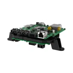
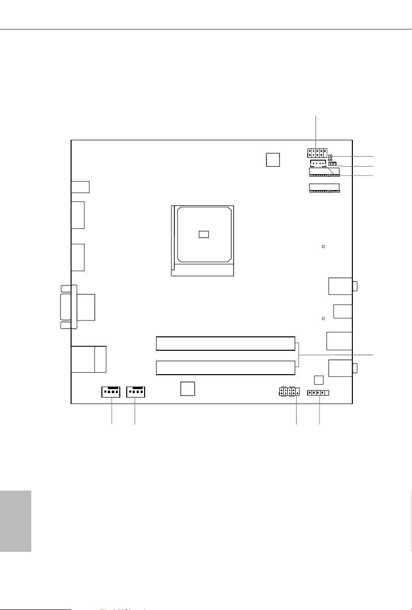
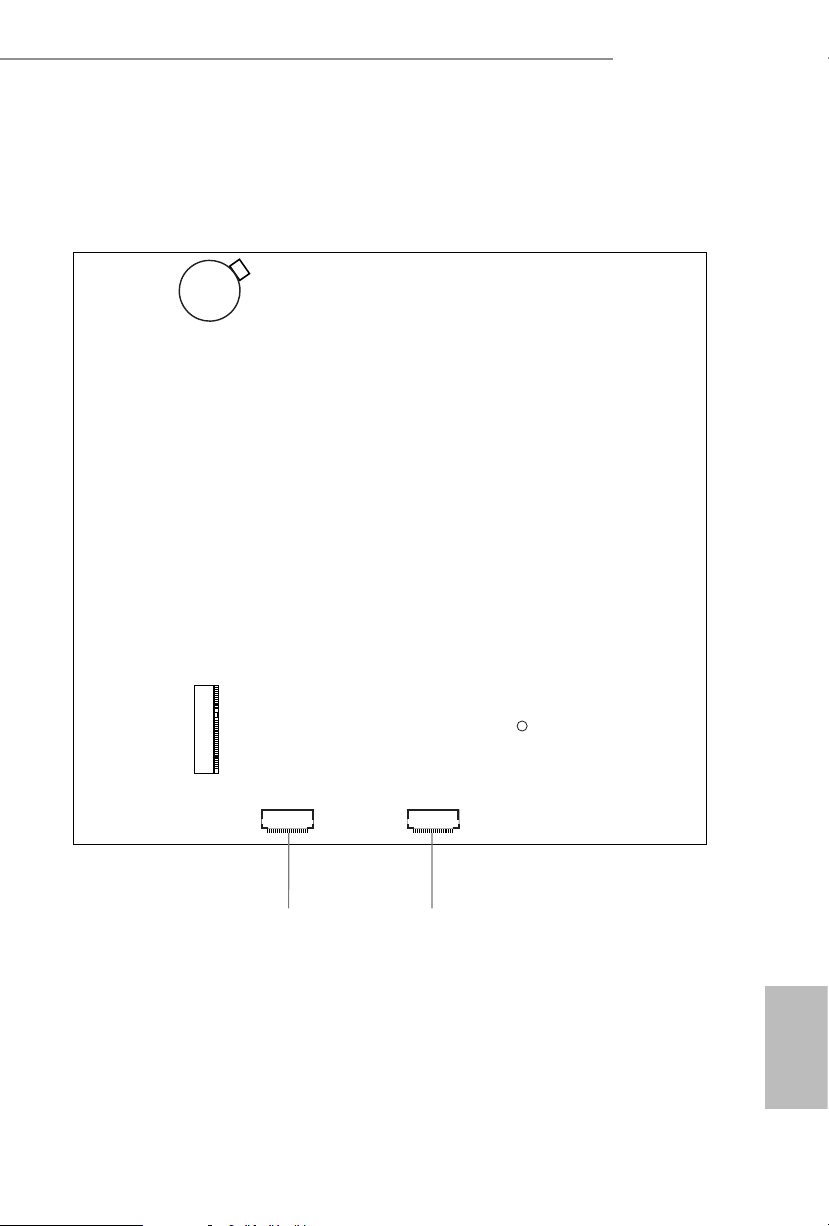
1.3 Motherboard Layout
Top:
RJ-45
T: USB 2.0
USB2
B: USB 3. 1 Gen1
USB3
5
Audio
CODEC
1
USB_4_5
HDLED RESET
PLED PWRBTN
PANEL1
1
Mic In
USB 3.1 Gen1
USB_TC_1
USB 3.1 Gen1
USB_1
Headphone
/ Headset
VGA1
9
DDR4_A1DDR4_A1
DDR4_B1
DC Jack
HDMI1
DP1
1
CI1
Supe r
I/O
BIOS
ROM
M.2 WiFi
M.2 PCIe SSD
CPU_FAN2
CPU_FAN1
1
1
AUDIO3
SOCKETAM4
A300M-STX
RoHS
8 7 6
3
1
CLRMOS1
2
SPEAKER1
1
4
A300M-STX
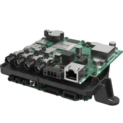
7
English
10 11
SATA3 SATA3
M2_2
CT1
CMOS
Battery
Back Side View

English
8
No. Description
1 USB 2.0 Header (USB_4_5)
2 Clear CMOS Jumper (CLRCMOS1)
3 Chassis Intrusion Header (CI1)
4 MONO Speaker Header
(SPEAKER1)
5 2 x 260-pin DDR4 SO-DIMM Slots (DDR4_A1, DDR4_B1)
6 Audio Header (AUDIO3)
7 System Panel Header (PANEL1)
8 CPU Fan Connector (CPU_FAN1)
9 CPU Fan Connector (CPU_FAN2)
10 SATA3 Connector (SATA2)
11 SATA3 Connector (SATA1)
A300M-STX
9
English
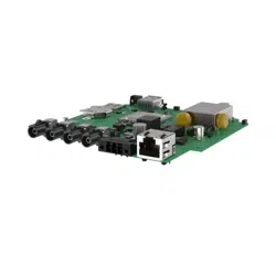
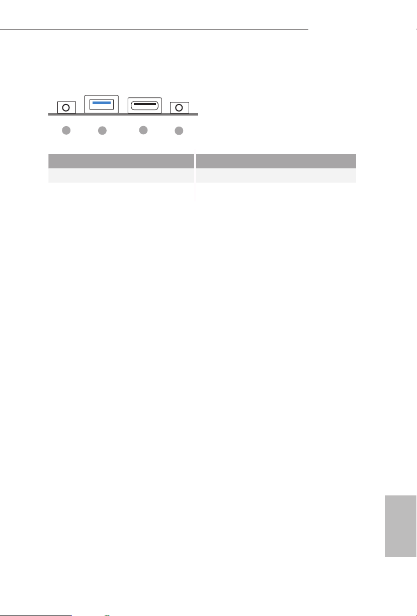
1.4 Front Panel
No. Description No. Description
1 Headphone/Headset Jack (AUDIO1) 3 USB 3.1 Gen1 Type-C Port (USB_TC_1)
2 USB 3.1 Gen1 Type-A Port (USB_1) 4 Microphone Input (AUDIO2)
1
2
3
4
English
10
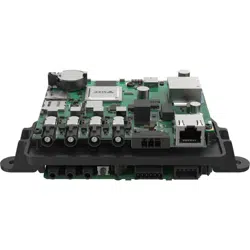
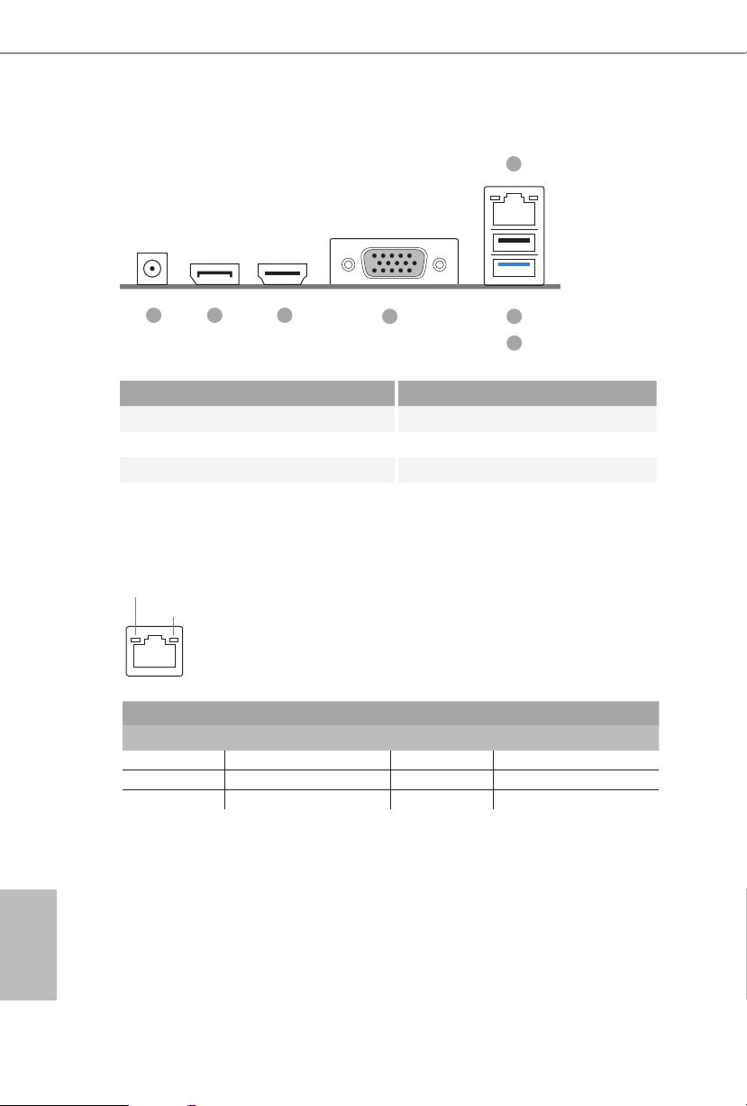
1.5 Rear Panel
No. Description No. Description
1 DC Jack 4 D-Sub Port
(Supports 19V DC Power Adapters) 5 USB 2.0 Port (USB_2)
2 Display Port 6 USB 3.1 Gen1 Port (USB_3)
3 HDMI Port 7 LAN RJ-45 Port*
* ere are two LEDs on each LAN port. Please refer to the table below for the LAN port LED indications.
Activity / Link LED Speed LED
Status Description Status Description
O No Link O 10Mbps connection
Blinking Data Activity Orange 100Mbps connection
On Link Green 1Gbps connection
ACT/LINK LED
SPEED LED
LAN Port
1 2 3
4 5
6
7

A300M-STX
11
English
is is a Mini-STX form factor motherboard. Before you install the motherboard,
study the conguration of your chassis to ensure that the motherboard ts into it.
Pre-installation Precautions
Take note of the following precautions before you install motherboard components
or change any motherboard settings.
•
Make sure to unplug the power cord before installing or removing the motherboard.
Failure to do so may cause physical injuries to you and damages to motherboard
components.
•
In order to avoid damage from static electricity to the motherboard’s components,
NEVER place your motherboard directly on a carpet. Also remember to use a grounded
wrist strap or touch a safety grounded object before you handle the components.
•
Hold components by the edges and do not touch the ICs.
•
Whenever you uninstall any components, place them on a grounded anti-static pad or
in the bag that comes with the components.
•
When placing screws to secure the motherboard to the chassis, please do not over-
tighten the screws! Doing so may damage the motherboard.
Chapter 2 Installation
English
12
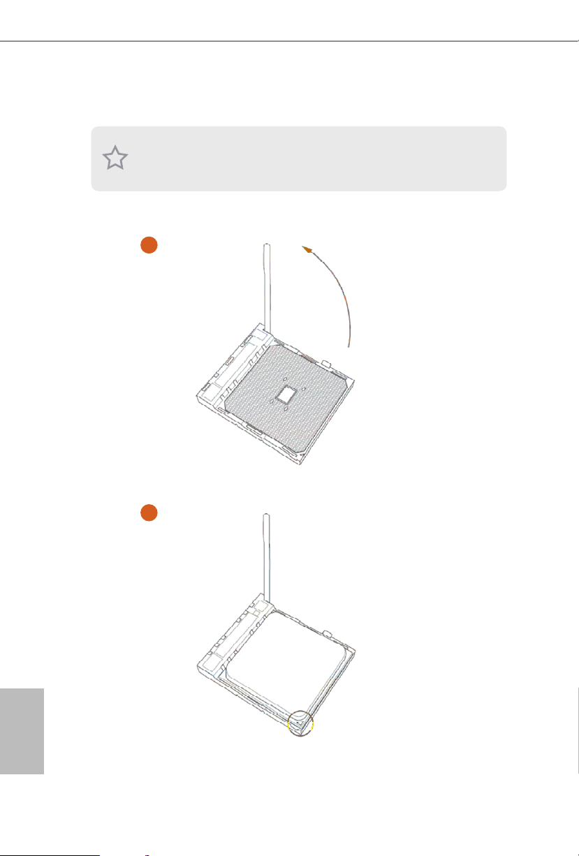
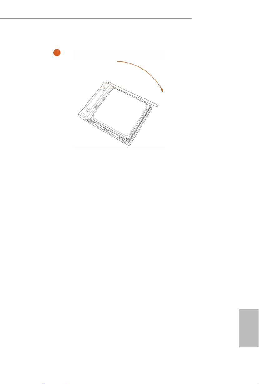
2.1 Installing the CPU
Unplug all power cables before installing the CPU.
2
1
A300M-STX
13
English
3
English
14
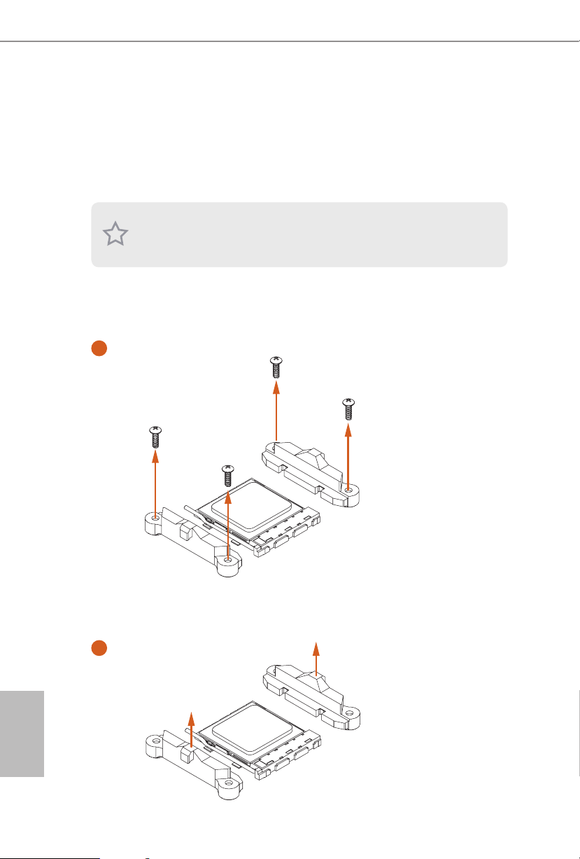
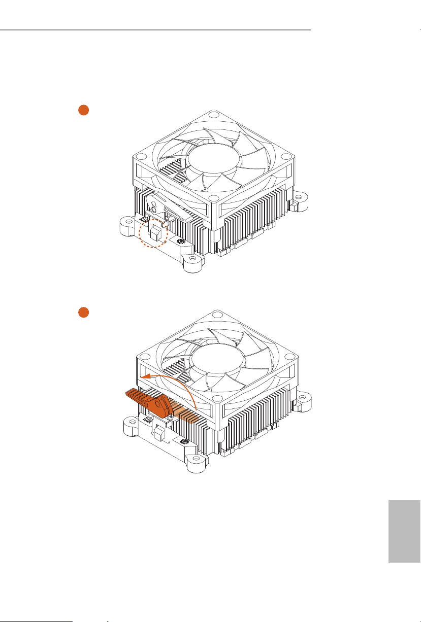
2.2 Installing the CPU Fan and Heatsink
Aer you install the CPU into this motherboard, it is necessary to install a larger
heatsink and cooling fan to dissipate heat. You also need to spray thermal grease
between the CPU and the heatsink to improve heat dissipation. Make sure that the
CPU and the heatsink are securely fastened and in good contact with each other.
Installing the CPU Box Cooler -1
Please turn o the power or remove the power cord before changing a CPU or heatsink.
1
2
A300M-STX
15
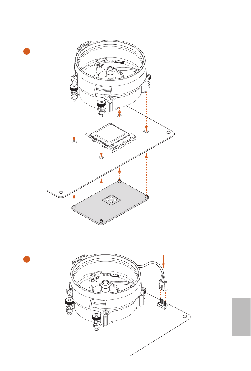
English
3
4
C
P
U
_
FA
N
1
4-pin FAN cable
English
16
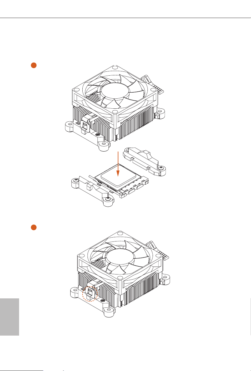
Installing the CPU Box Cooler -2
1
2
A300M-STX
17
English
3
4
English
18
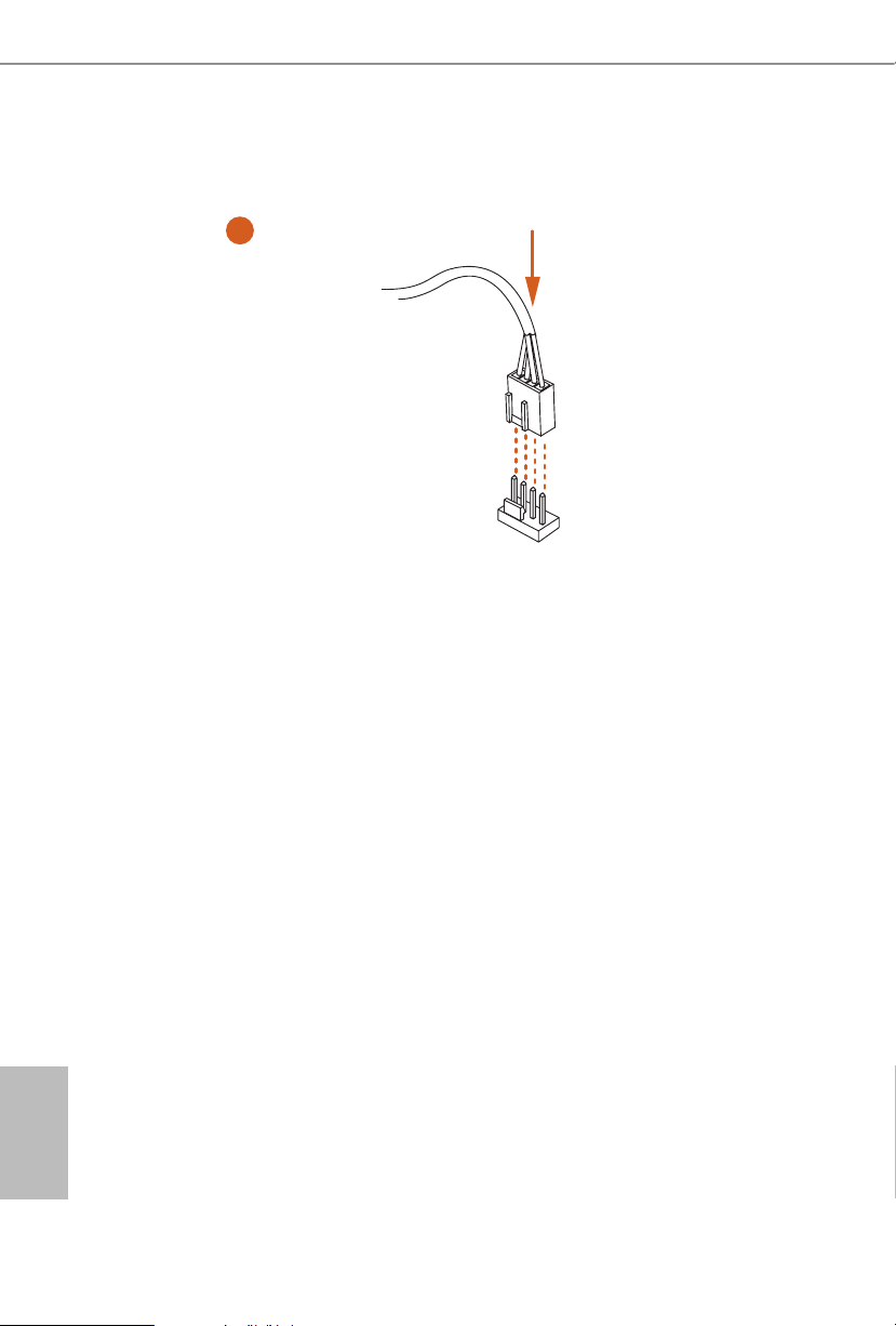
4-pin FAN cable
5
CPU_F
AN1

A300M-STX
19
English
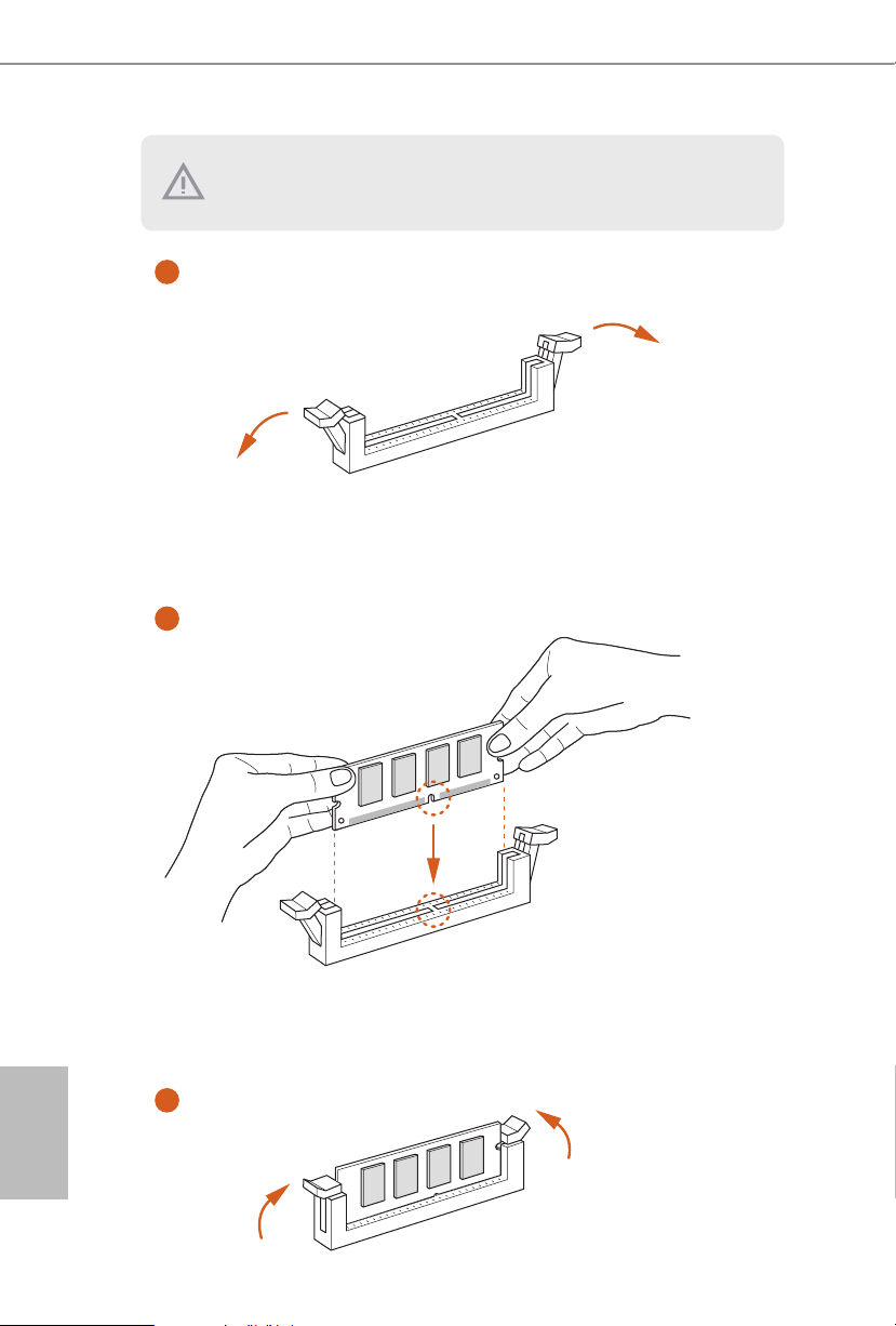
2.3 Installing Memory Modules (SO-DIMM)
is motherboard provides two 260-pin DDR4 (Double Data Rate 4) SO-DIMM
slots.
DDR4 SO-DIMM Maximum Frequency Support
A-Series APUs:
Ryzen Series CPUs (Raven Ridge):
SR: Single rank DIMM, 1Rx4 or 1Rx8 on DIMM module label
DR: Dual rank DIMM, 2Rx4 or 2Rx8 on DIMM module label
SO-DIMM Memory Slot
Frequency
(Mhz)
A1 B1
- SR 2400
SR - 2400
- DR 2400
DR - 2400
SR SR 2400
DR DR 2400
SO-DIMM Memory Slot
Frequency
(Mhz)
A1 B1
- SR 2933
SR - 2933
- DR 2667
DR - 2667
SR SR 2667
DR DR 2400
It is not allowed to install a DDR, DDR2 or DDR3 memory module into a DDR4 slot;
otherwise, this motherboard and SO-DIMM may be damaged.
English
20
e DIMM only ts in one correct orientation. It will cause permanent damage to
the motherboard and the DIMM if you force the DIMM into the slot at incorrect
orientation.
1
2
3
A300M-STX
21
English
If you clear the CMOS, the case open may be detected. Please adjust the BIOS option
“Clear Status” to clear the record of previous chassis intrusion status.
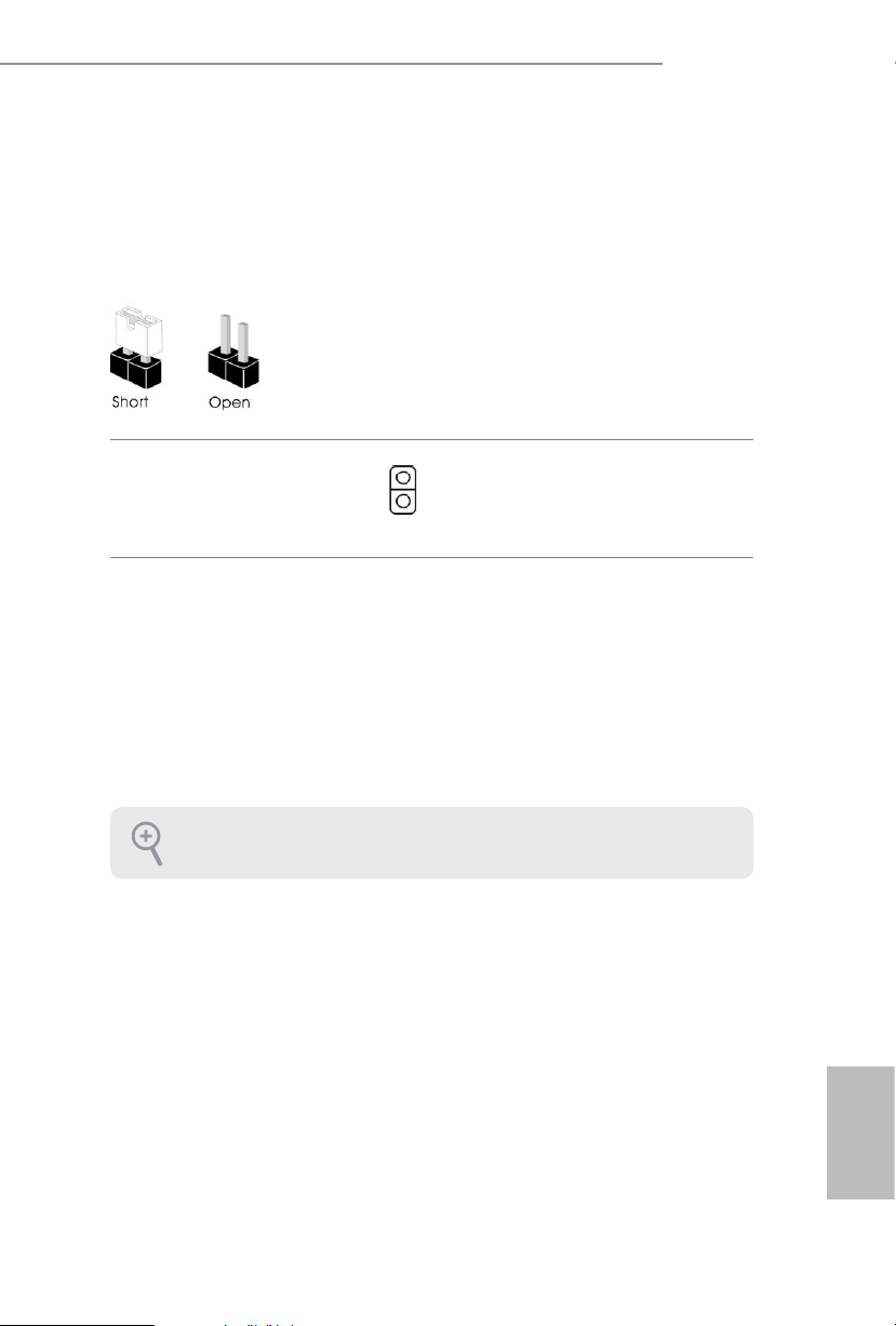
2.4 Jumpers Setup
e illustration shows how jumpers are setup. When the jumper cap is placed on
the pins, the jumper is “Short”. If no jumper cap is placed on the pins, the jumper is
“Open”.
Clear CMOS Jumper
(CLRCMOS1)
(see p.6, No. 2)
Short: Clear CMOS
Open: Default
CLRCMOS1 allows you to clear the data in CMOS. e data in CMOS includes
system setup information such as system password, date, time, and system setup
parameters. To clear and reset the system parameters to default setup, please
turn o the computer and unplug the power cord, then use a jumper cap to short
the pins on CLRCMOS1 for 3 seconds. Please remember to remove the jumper
cap aer clearing the CMOS. If you need to clear the CMOS when you just nish
updating the BIOS, you must boot up the system rst, and then shut it down
before you do the clear-CMOS action.
2-pin Jumper
English
22
2.5 Onboard Headers and Connectors
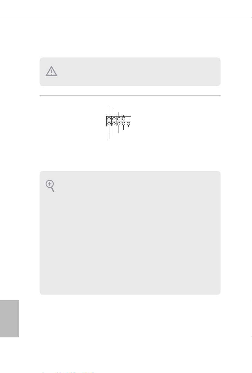
System Panel Header
(9-pi n PANEL1)
(see p.6, No. 7)
Connect the power
button, reset button and
system status indicator on
the chassis to this header
according to the pin
assignments below. Note
the positive and negative
pins before connecting
the cables.
GND
R ESET#
PWRBTN#
PLED-
PLED+
GND
HDLED-
HDLED+
1
GND
Onboard headers and connectors are NOT jumpers. Do NOT place jumper caps over these
headers and connectors. Placing jumper caps over the headers and connectors will cause
permanent damage to the motherboard.
PWRBTN (Power Button):
Connect to the power button on the chassis front panel. You may congure the way to turn
o your system using the power button.
RESET (Reset Button):
Connect to the reset button on the chassis front panel. Press the reset button to restart the
computer if the computer freezes and fails to perform a normal restart.
PLED (System Power LED):
Connect to the power status indicator on the chassis front panel. e LED is on when the
system is operating. e LED keeps blinking when the system is in S1/S3 sleep state. e
LED is o when the system is in S4 sleep state or powered o (S5).
HDLED (Hard Drive Activity LED):
Connect to the hard drive activity LED on the chassis front panel. e LED is on when the
hard drive is reading or writing data.
e front panel design may dier by chassis. A front panel module mainly consists of power
button, reset button, power LED, hard drive activity LED, speaker and etc. When connect-
ing your chassis front panel module to this header, make sure the wire assignments and the
pin assignments are matched correctly.
A300M-STX
23
English
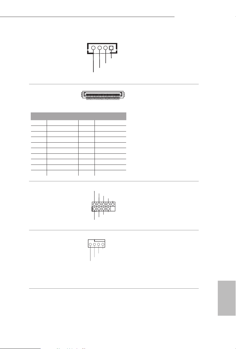
MONO Speaker Header
(4-pin SPEAKER1)
(see p.6, No. 4)
Please connect the chassis
speaker to this header.
Serial ATA3 Connectors
(see p.7, No. 9 and 10)
ese two SATA3
connectors support SATA
data cables for internal
storage devices with up to
6.0 Gb/s data transfer rate.
*e SATA3 connectors
support 2.5-inch hard
drive (+5V) and do not
support 3.5-inch hard
drive (+12V)
USB 2.0 Header
(9-pin USB_4_5)
(see p.6, No. 1)
ere is one header on
this motherboard. is
USB 2.0 header can
support two ports.
CPU Fan Connectors
(4-pin CPU_FAN1)
(see p.6, No. 8)
(4-pin CPU_FAN2)
(see p.6, No. 9)
is motherboard
provides two 4-Pin CPU
fan (Quiet Fan)
connectors. If you plan to
connect a 3-Pin CPU fan,
please connect it to Pin
1-3.
DUMMY
GND
GND
P+
P-
USB_PWR
P+
P-
U SB_PWR
1
1
20
PIN Signal Name PIN Signal Name
1 GND 11 N/A
2 LVDS _TX+ 12 5V
3 LVDS _TX- 13 5V
4 GND 14 5V
5 GND 15 5V
6 LVDS _RX- 16 5V
7 LVDS_R X+ 17 N/A
8 GND 18 GND
9 GND 19 GND
10 GND 20 GND
CPU_F
FAN_VOLTAGE
GND
AN_SPEED
FAN_SPEED_CONTROL
4 3 2 1
Front_L+
Front_R-
Front_R+
Front_L-
1
English
24
1
Signal
GND
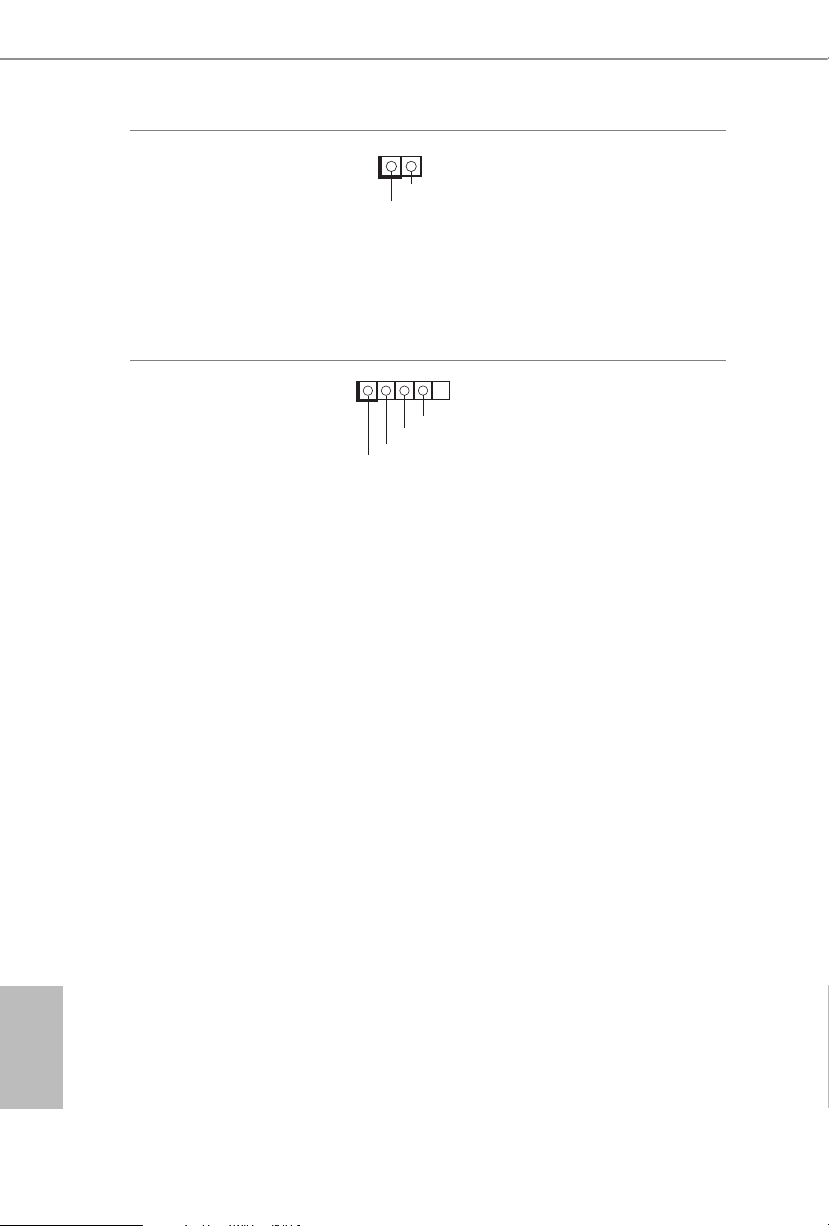
Chassis Intrusion Header
(2-pin CI1)
(see p.6, No. 3)
is motherboard
supports CASE OPEN
detection feature that
detects if the chassis cove
has been removed. is
feature requires a chassis
with chassis intrusion
detection design.
Audio Header
(5-pin AUDIO3)
(see p.6, No. 6)
is Audio header allows you to
connect the audio cable for head-
phone.
1
GND
Jack detect
Audio-L
Audio-R
A300M-STX
25
English
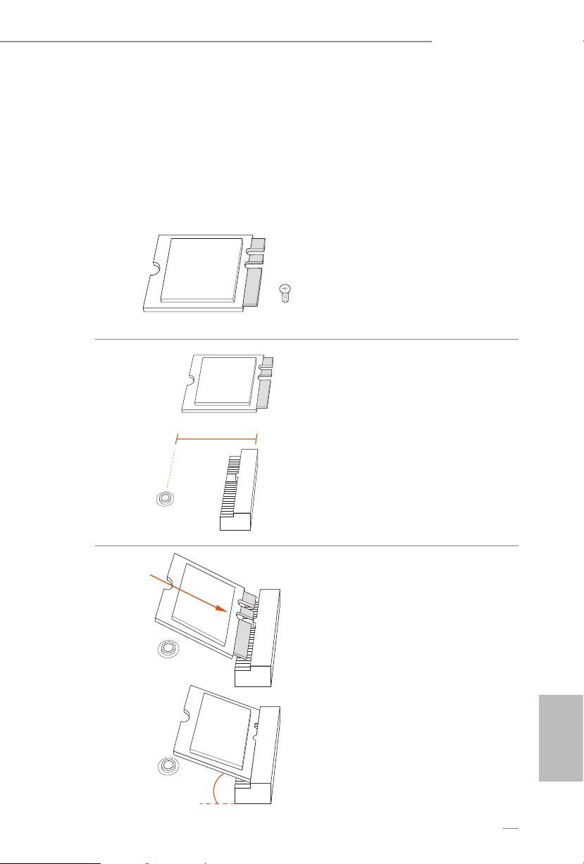
2.6 M.2 WiFi/BT Module Installation Guide
e M.2, also known as the Next Generation Form Factor (NGFF), is a small size and
versatile card edge connector that aims to replace mPCIe and mSATA. e M.2 Socket (Key
E) supports type 2230 WiFi/BT module.
Installing the WiFi/BT module
Step 1
Prepare a type 2230 WiFi/BT module
and the screw.
PCB Length: 3cm
Module Type: Type2230
A
Step 2
Find the nut location to be used.
A
A
20
o
Step 3
Gently insert the WiFi/BT module
into the M.2 slot. Please be aware
that the module only ts in one
orientation.
English
26
A
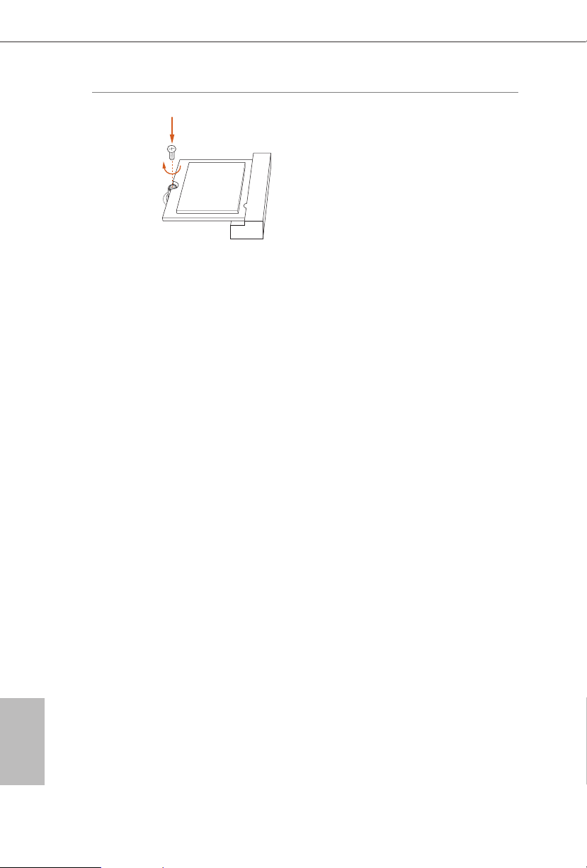
Step 4
Tighten the screw with a screwdriver
to secure the module into place.
Please do not overtighten the screw as
this might damage the module.
A300M-STX
27
English
2.7 M.2_SSD (NGFF) Module Installation Guide
e M.2, also known as the Next Generation Form Factor (NGFF), is a small size and
versatile card edge connector that aims to replace mPCIe and mSATA. The Ultra M.2
Socket (M2_1) supports type 2280 M.2 PCI Express module up to Gen3 x4 (32 Gb/s). e
Ultra M.2 Socket (M2_2) supports type 2280 M.2 PCI Express module up to Gen3 x4 (32
Gb/s) (with A-Series APU and Raven Ridge) or Gen3 x2 (16 Gb/s) (with Athlon 2xxGE
series).
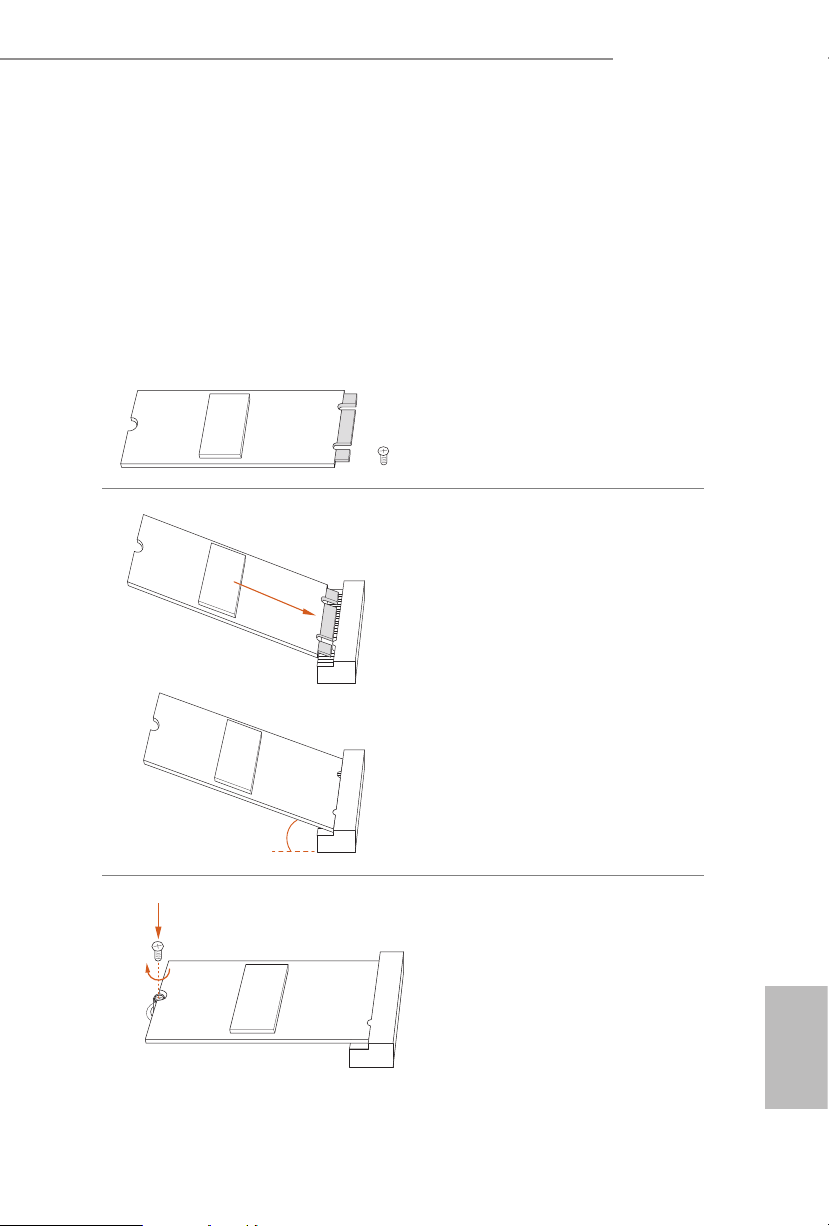
Installing the M.2_SSD (NGFF) Module
Step 1
Prepare a M.2_SSD (NGFF) module
and the screw.
Step 2
Gently insert the M.2 (NGFF) SSD
module into the M.2 slot. Please
be aware that the M.2 (NGFF) SSD
module only ts in one orientation.
Step 3
Tighten the screw with a
screwdriver to secure the
module into place. Please do
not overtighten the screw as
this might damage the module.
20
o
NUT1NUT2

English
28
M.2_SSD (NGFF) Module Support List
Vendor Interface P/N
ADATA PCIe ADATA ASX7000NPC-512GT-C (XPG SX7000) (NVMe)
ADATA PCIe ADATA ASX8000NPC-512GM-C (XPG ASX8000) (NVMe)
Apacer PCIe Apacer Z280 AP240GZ280-240G (NVMe)
Intel PCIe Intel Optane Memory 32GB (MEMPEK1W032GA)(NVMe)
Intel PCIe Intel Optane Memory 16GB (MEMPEK1W016GA)(NVMe)
INTEL PCIe INTEL 600P-SSDPEKKW256G7-256GB (NVMe)
INTEL PCIe INTEL 600P-SSDPEKKW128G7-128GB (NVMe)
INTEL PCIe INTEL 6000P-SSDPEKKF256G7-256GB (NVMe)
INTEL PCIe INTEL 6000P-SSDPEKKF512G7-512GB (NVMe)
Kingston PCIe Kingston SHPM2280P2/240G
PATR IOT PCIe PATRIOT Hellre M2 (240G) (NVMe)
PLEXTOR PCIe PLEXTOR PX-256M8PeG (NVMe)
PLEXTOR PCIe PLEXTOR PX-256M8SeGN (NVMe)
Samsung PCIe Samsung XP941-512G (MZHPU512HCGL)
Samsung PCIe Samsung 950Pro-512G (NVMe)
Samsung PCIe Samsung 950Pro-256G (NVMe)
Samsung PCIe Samsung MZ-VLW1280 (PM961) (NVMe)
Samsung PCIe Samsung MZ-VPW1280 (SM961) (NVMe)
TOSHIBA PCIe TOSHIBA XG3-128G (NVMe)
TOSHIBA PCIe TOSHIBA OCZ RD400-256G (NVMe)
WD PCIe WD WDS512G1X0C-00ENX0 (NVMe)
WD PCIe WD WDS256G1X0C-00ENX0 (NVMe)
For the latest updates of M.2_SSD (NFGG) module support list, please visit our website for
details.

A300M-STX
29
English
Chapter 3 Software and Utilities Operation
3.1 Installing Drivers
e Support CD that comes with the motherboard contains necessary drivers and
useful utilities that enhance the motherboard’s features.
Running The Support CD
To begin using the support CD, insert the CD into your CD-ROM drive. e CD
automatically displays the Main Menu if “AUTORUN” is enabled in your computer.
If the Main Menu does not appear automatically, locate and double click on the le
“ASRSETUP.EXE” in the Support CD to display the menu.
Drivers Menu
e drivers compatible to your system will be auto-detected and listed on the
support CD driver page. Please click Install All or follow the order from top to
bottom to install those required drivers. erefore, the drivers you install can work
properly.
Utilities Menu
e Utilities Menu shows the application soware that the motherboard supports.
Click on a specic item then follow the installation wizard to install it.
English
30
Chapter 4 UEFI SETUP UTILITY
4.1 Introduction
is section explains how to use the UEFI SETUP UTILITY to congure your
system. You may run the UEFI SETUP UTILITY by pressing <F2> or <Del> right
aer you power on the computer, otherwise, the Power-On-Self-Test (POST) will
continue with its test routines. If you wish to enter the UEFI SETUP UTILITY aer
POST, restart the system by pressing <Ctl> + <Alt> + <Delete>, or by pressing the
reset button on the system chassis. You may also restart by turning the system o
and then back on.
4.1.1 UEFI Menu Bar
e top of the screen has a menu bar with the following selections:
Main
For setting system time/date information
OC Tweaker
For overclocking congurations
Advanced
For advanced system congurations
Tool
Useful tools
H/W Monitor
Displays current hardware status
Boot
For conguring boot settings and boot priority
Security
For security settings
Exit
Exit the current screen or the UEFI Setup Utility
Because the UEFI soware is constantly being updated, the following UEFI setup screens
and descriptions are for reference purpose only, and they may not exactly match what you
see on your screen.
A300M-STX
31
English
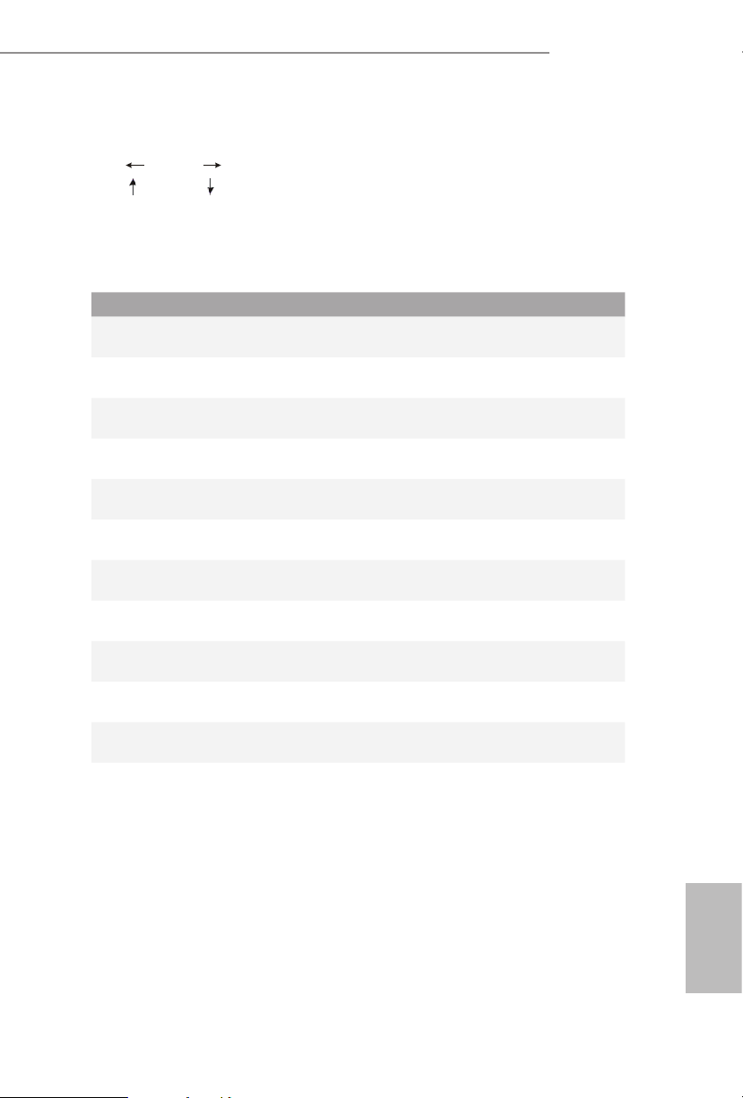
4.1.2 Navigation Keys
Use < > key or < > key to choose among the selections on the menu bar, and
use < > key or < > key to move the cursor up or down to select items, then
press <Enter> to get into the sub screen. You can also use the mouse to click your
required item.
Please check the following table for the descriptions of each navigation key.
Navigation Key(s) Description
+ / -
To change option for the selected items
<Tab>
Switch to next function
<PGUP>
Go to the previous page
<PGDN>
Go to the next page
<HOME>
Go to the top of the screen
<END>
Go to the bottom of the screen
<F1>
To display the General Help Screen
<F7>
Discard changes and exit the SETUP UTILITY
<F9>
Load optimal default values for all the settings
<F10>
Save changes and exit the SETUP UTILITY
<F12>
Print screen
<ESC>
Jump to the Exit Screen or exit the current screen
English
32
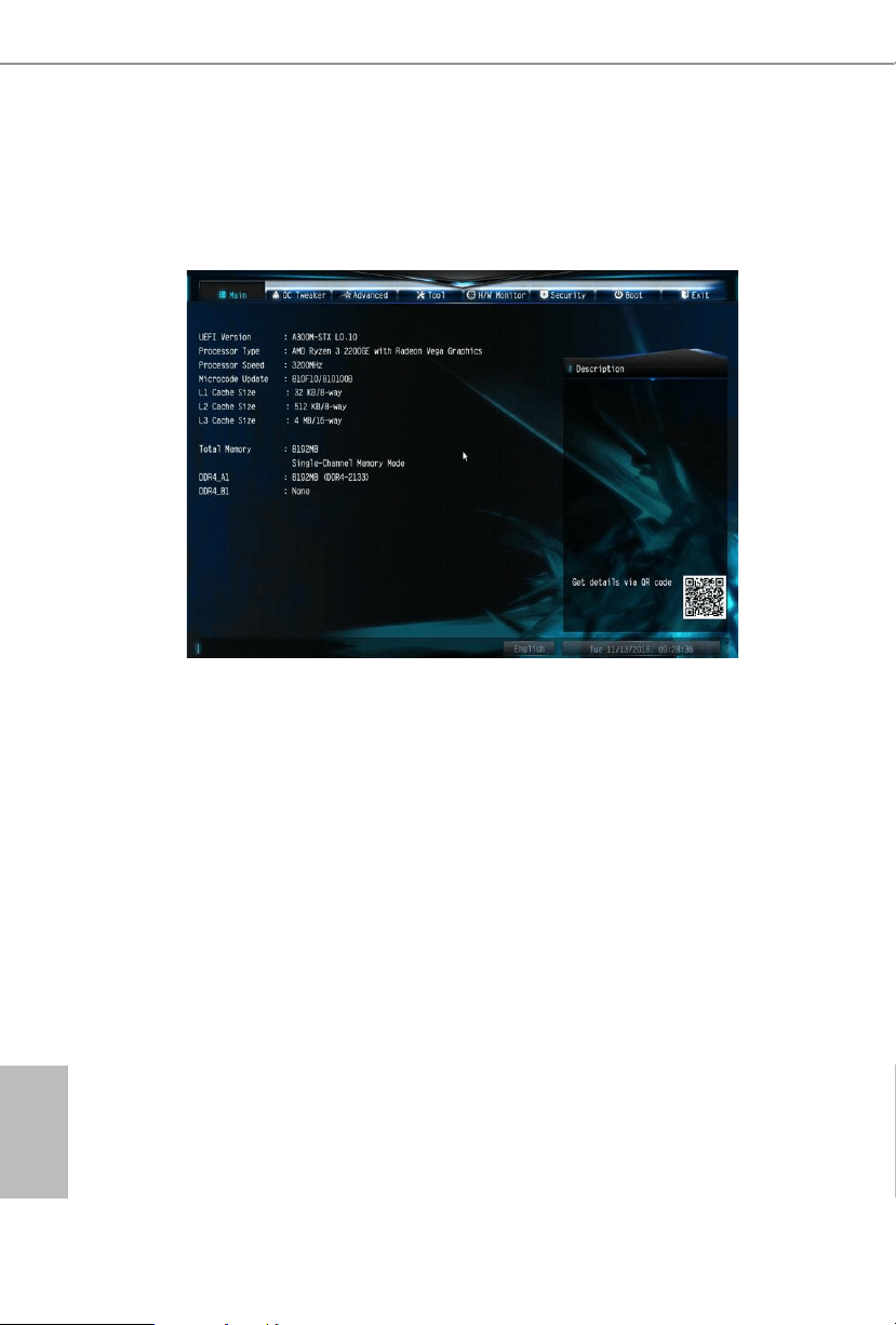
4.2 Main Screen
When you enter the UEFI SETUP UTILITY, the Main screen will appear and
display the system overview.
A300M-STX
33
English
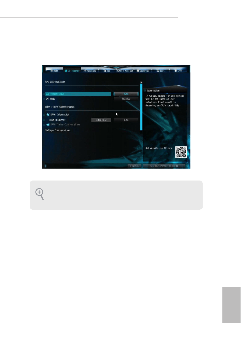
4.3 OC Tweaker Screen
In the OC Tweaker screen, you can set up overclocking features.
CPU Conguration
SOC Voltage(VID)
Congure the voltage for the VID-requested SOC supply level.
SMT Mode
is item can be used to disable symmetric multithreading. To re-enable SMT, a
power cycle is needed aer selecting [Auto].
Warning: S3 is not supported on systems where SMT is disabled.
DRAM Timing Conguration
DRAM Information
Browse the serial presence defect (SPD) for DDR4 modules.
Because the UEFI soware is constantly being updated, the following UEFI setup
screens and descriptions are for reference purpose only, and they may not exactly
match what you see on your screen.

English
34
DRAM Frequency
If [Auto] is selected, the motherboard will detect the memory module(s) inserted
and assign the appropriate frequency automatically.
Voltage Conguration
DRAM Voltage
Use this to select DRAM Voltage. e default value is [Auto].
Save User Default
Type a prole name and press enter to save your settings as user default.
Load User Default
Load previously saved user defaults.
Save User UEFI Setup Prole to Disk
Save current UEFI settings as an user default prole to disk.
Load User UEFI Setup Prole to Disk
Load previously saved user defaults from the disk.
A300M-STX
35
English
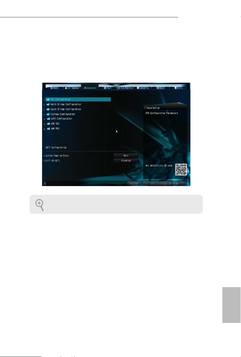
4.4 Advanced Screen
In this section, you may set the congurations for the following items: CPU
Conguration, North Bridge Conguration, South Bridge Conguration, Storage-
Conguration, ACPI Conguration, AMD CBS and AMD PBS.
UEFI Conguration
Active Page on Entry
Select the default page when entering the UEFI setup utility.
Full HD UEFI
When [Auto] is selected, the resolution will be set to 1920 x 1080 if the monitor
supports Full HD resolution. If the monitor does not support Full HD resolution,
then the resolution will be set to 1024 x 768. When [Disable] is selected, the
resolution will be set to 1024 x 768 directly.
Setting wrong values in this section may cause the system to malfunction.
English
36
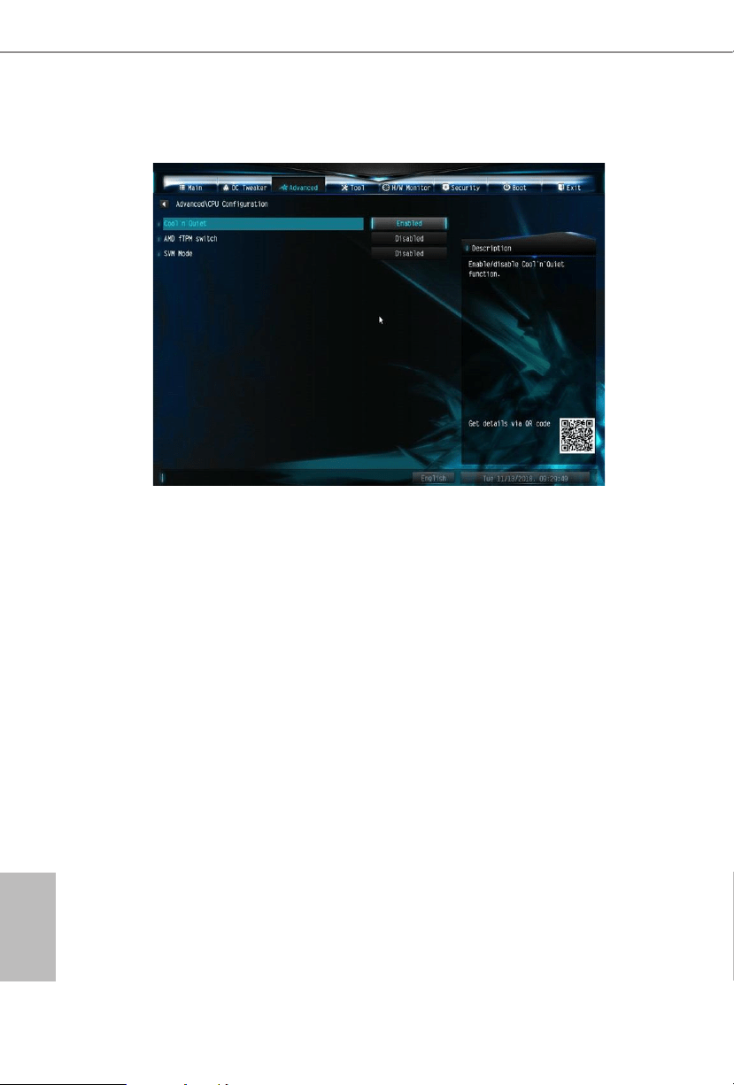
4.4.1 CPU Conguration
Cool 'n' Quiet
Use this item to enable or disable AMD’s Cool ‘n’ Quiet
TM
technology. e default value is
[Enabled]. Conguration options: [Enabled] and [Disabled]. If you install Windows
®
OS and
want to enable this function, please set this item to [Enabled]. Please note that enabling this
function may reduce CPU voltage and memory frequency, and lead to system stability or
compatibility issue with some memory modules or power supplies. Please set this item to
[Disable] if above issue occurs.
AMD fTPM Switch
Use this to enable or disable AMD CPU fTPM.
SVM Mode
When this option is set to [Enabled], a VMM (Virtual Machine Architecture) can
utilize the additional hardware capabilities provided by AMD-V. e default value is
[Enabled]. Conguration options: [Enabled] and [Disabled].
A300M-STX
37
English
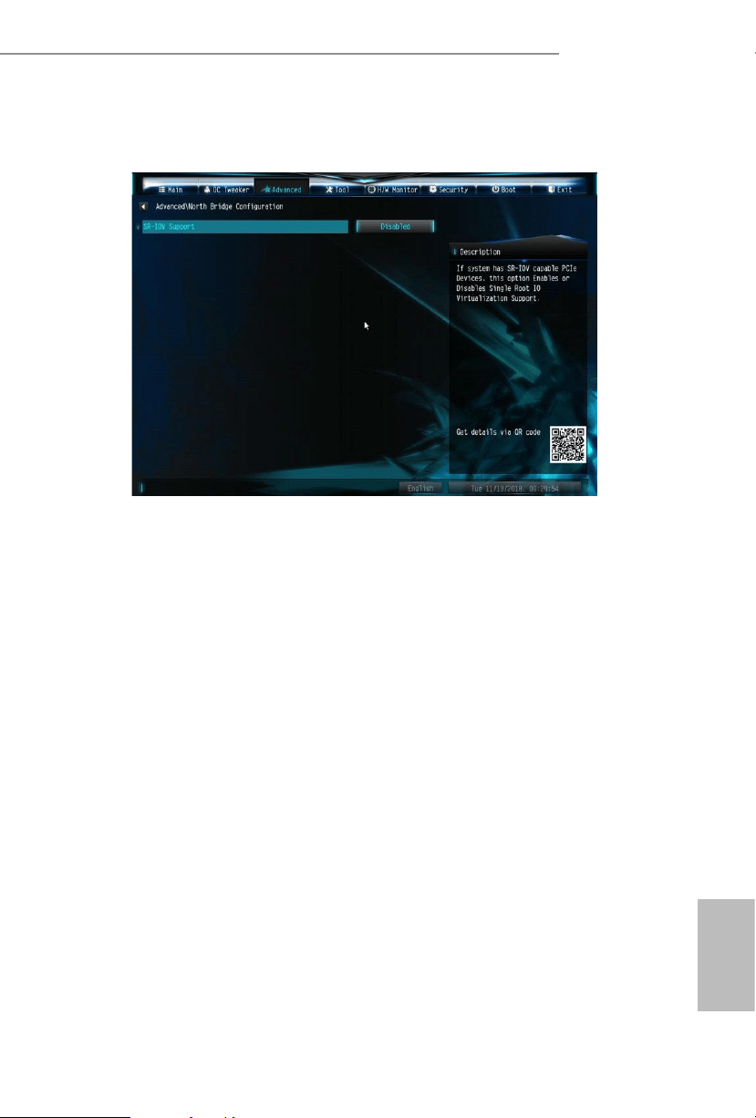
4.4.2 North Bridge Conguration
SR-IOV Support
Enable/disable the SR-IOV (Single Root IO Virtualization Support) if the system
has SR-IOV capable PCIe devices.
English
38
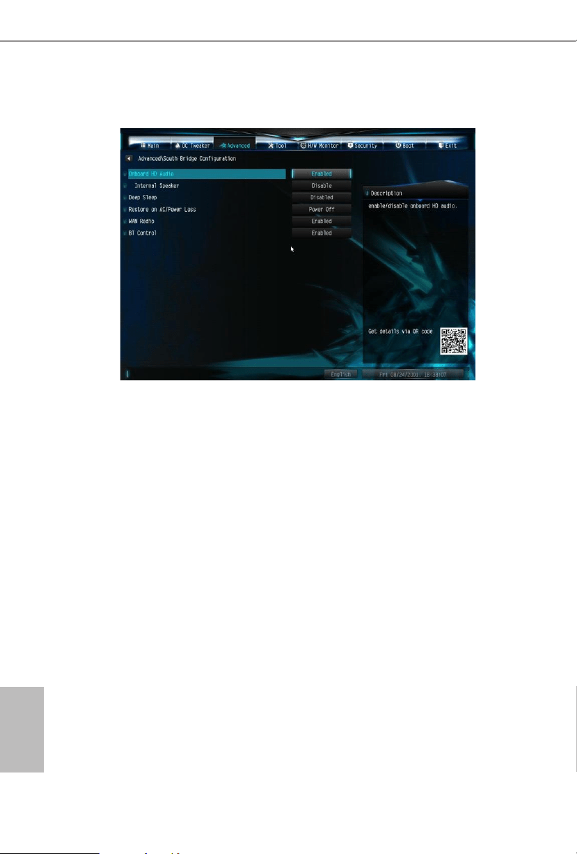
4.4.3 South Bridge Conguration
Onboard HD Audio
Enable/disable onboard HD audio. Set to Auto to enable onboard HD audio and
automatically disable it when a sound card is installed.
Internal Speaker
Select Internal Speaker.
Deep Sleep
Congure deep sleep mode for power saving when the computer is shut down.
Restore on AC/Power Loss
Select the power state aer a power failure. If [Power O] is selected, the power will
remain o when the power recovers. If [Power On] is selected, the system will start
to boot up when the power recovers.
WAN Radio
Enable/disable the WiFi module's connectivity.
BT Control
Enable/disable the bluetooth's connectivity.
A300M-STX
39
English
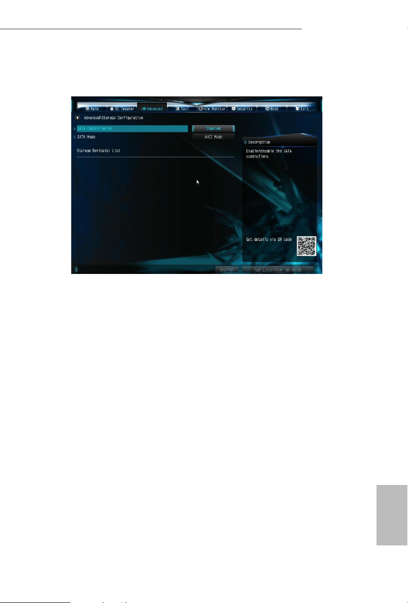
4.4.4 Storage Conguration
SATA Controller(s)
Enable/disable the SATA controllers.
SATA Mode
AHCI: Supports new features that improve performance.
RAID: Combine multiple disk drives into a logical unit.
English
40
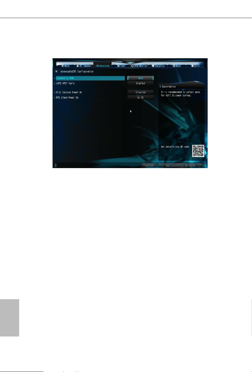
4.4.5 ACPI Conguration
Suspend to RAM
It is recommended to select auto for ACPI S3 power saving.
ACPI HPET Table
Enable the High Precision Event Timer for better performance and to pass WHQL
tests.
Onboard LAN Power On
Allow the system to be waked up by a onboard LAN.
RTC Alarm Power On
Allow the system to be waked up by the real time clock alarm. Set it to By OS to let
it be handled by your operating system.
A300M-STX
41
English
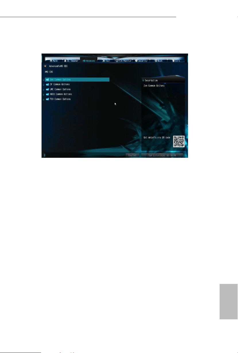
4.4.6 AMD CBS
e AMD CBS menu accesses AMD specic features.
English
42
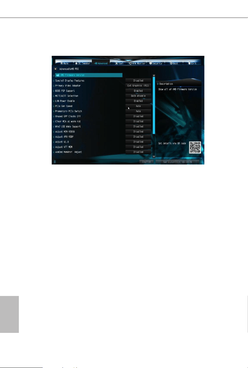
4.4.7 AMD PBS
e AMD PBS menu accesses AMD specic features.
A300M-STX
43
English
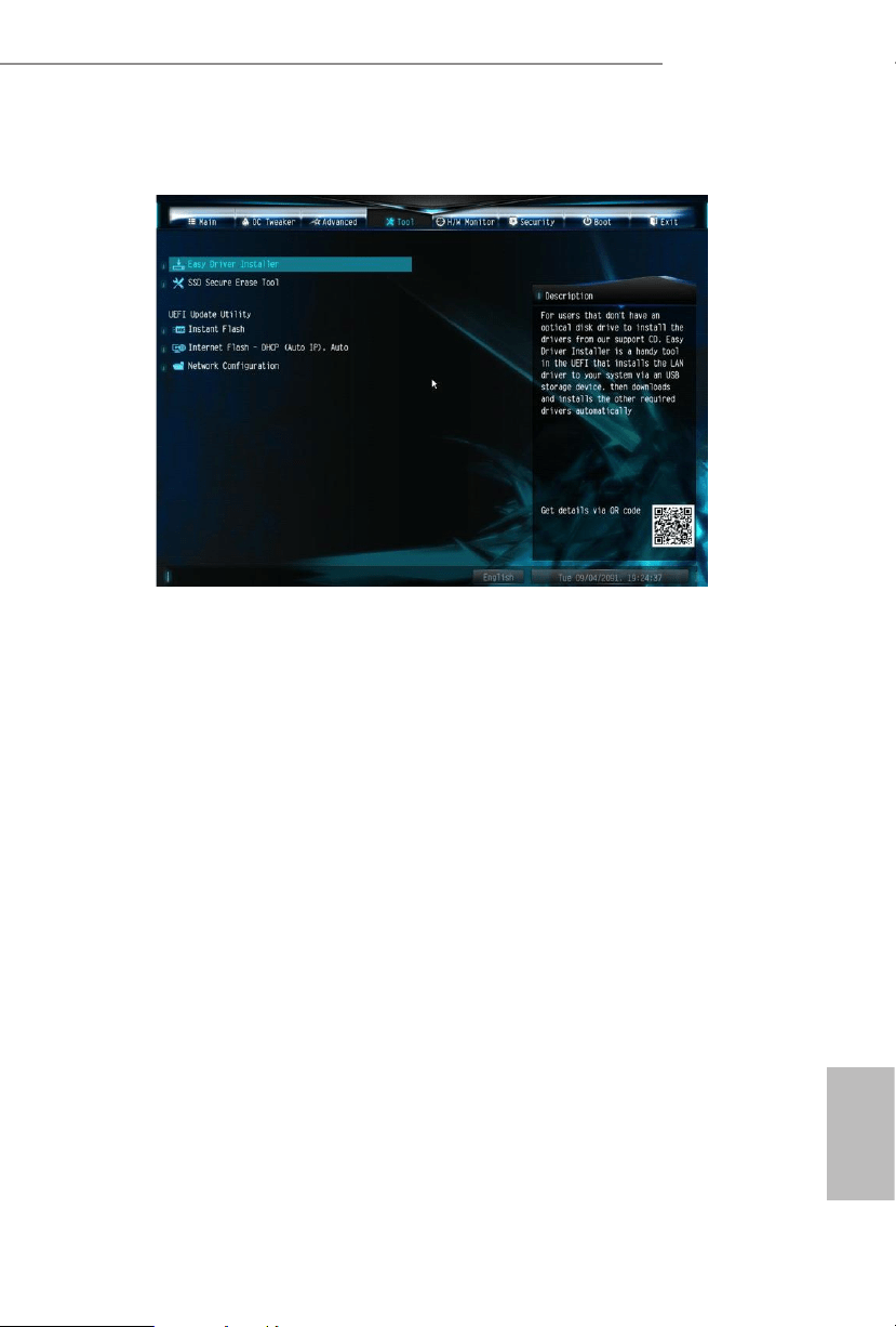
4.5 Tools
Easy Driver Installer
For users that don’t have an optical disk drive to install the drivers from our support
CD, Easy Driver Installer is a handy tool in the UEFI that installs the LAN driver
to your system via an USB storage device, then downloads and installs the other
required drivers automatically.
SSD Secure Erase Tool
Use this tool to securely erase SSD.
Instant Flash
Save UEFI les in your USB storage device and run Instant Flash to update your
UEFI.
English
44
Internet Flash - DHCP (Auto IP), Auto
Internet Flash downloads and updates the latest UEFI rmware version from our
servers for you. Please setup network conguration before using Internet Flash.
*For BIOS backup and recovery purpose, it is recommended to plug in your USB
pen drive before using this function.
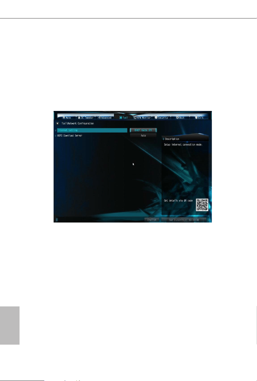
Network Conguration
Use this to congure internet connection settings for Internet Flash.
Internet Setting
Enable or disable sound eects in the setup utility.
UEFI Download Server
Select a server to download the UEFI rmware.
A300M-STX
45
English
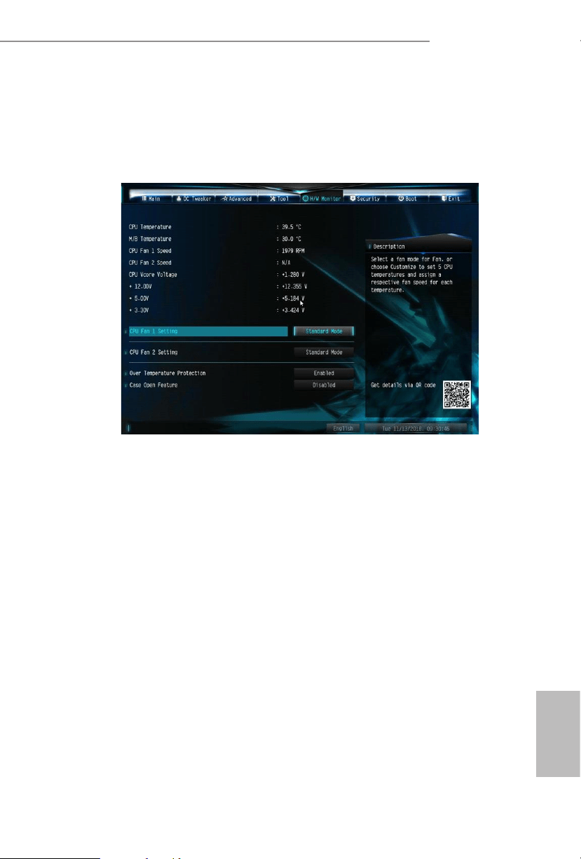
4.6 Hardware Health Event Monitoring Screen
is section allows you to monitor the status of the hardware on your system,
including the parameters of the CPU temperature, motherboard temperature, fan
speed and voltage.
CPU Fan 1 Setting
Select a fan mode for CPU Fan 1, or choose Customize to set 5 CPU temperatures
and assign a respective fan speed for each temperature.
CPU Fan 2 Setting
Select a fan mode for CPU Fan 2, or choose Customize to set 5 CPU temperatures
and assign a respective fan speed for each temperature.
Over Temperature Protection
When Over Temperature Protection is enabled, the system automatically shuts
down when the motherboard is overheated.
Case Open Feature
Enable or disable Case Open Feature to detect whether the chassis cover has been
removed.
English
46
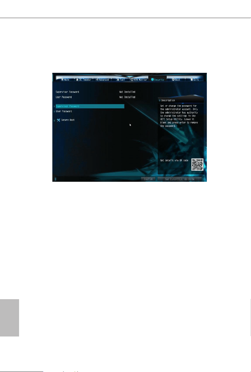
4.7 Security Screen
In this section you may set or change the supervisor/user password for the system.
You may also clear the user password.
Supervisor Password
Set or change the password for the administrator account. Only the administrator
has authority to change the settings in the UEFI Setup Utility. Leave it blank and
press enter to remove the password.
User Password
Set or change the password for the user account. Users are unable to change the
settings in the UEFI Setup Utility. Leave it blank and press enter to remove the
password.
Secure Boot
Enable to support Secure Boot.
A300M-STX
47
English
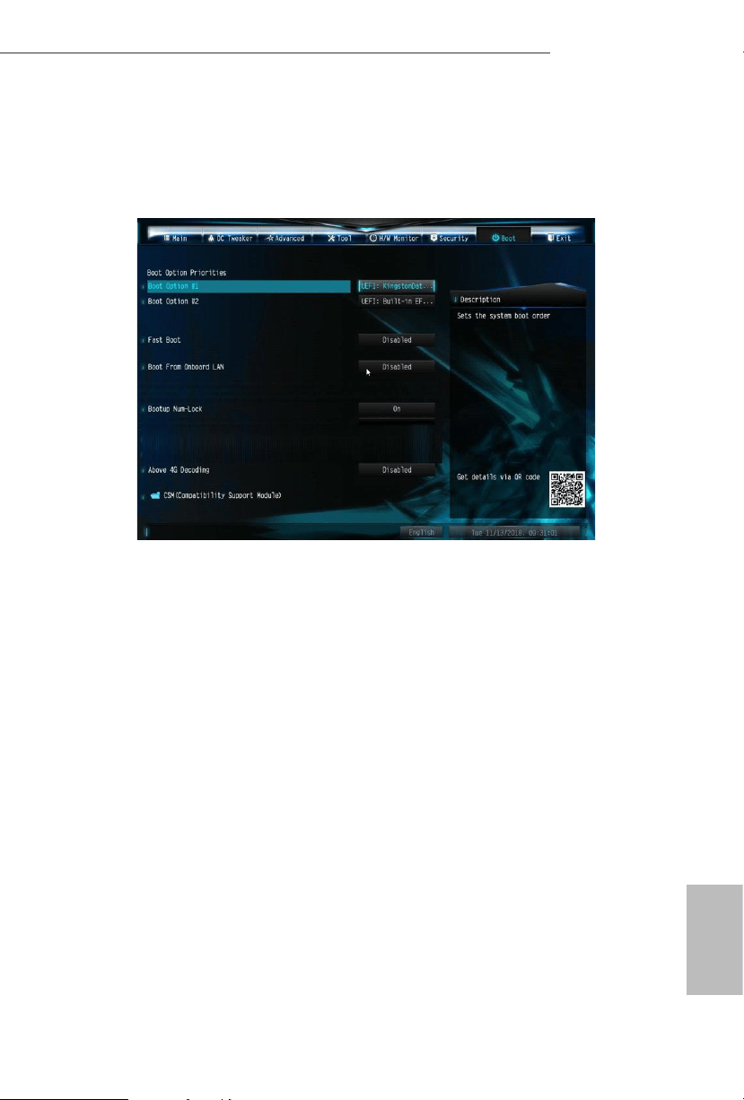
4.8 Boot Screen
is section displays the available devices on your system for you to congure the
boot settings and the boot priority.
Fast Boot
Fast Boot minimizes your computer's boot time. In fast mode you may not boot
from an USB storage device.
Boot From Onboard LAN
Allow the system to be waked up by the onboard LAN.
Bootup Num-Lock
Select whether Num Lock should be turned on or o when the system boots up.
English
48
Above 4G Decoding
Enable/disable the 64-bit capable devices to be decoded in above 4G address space.
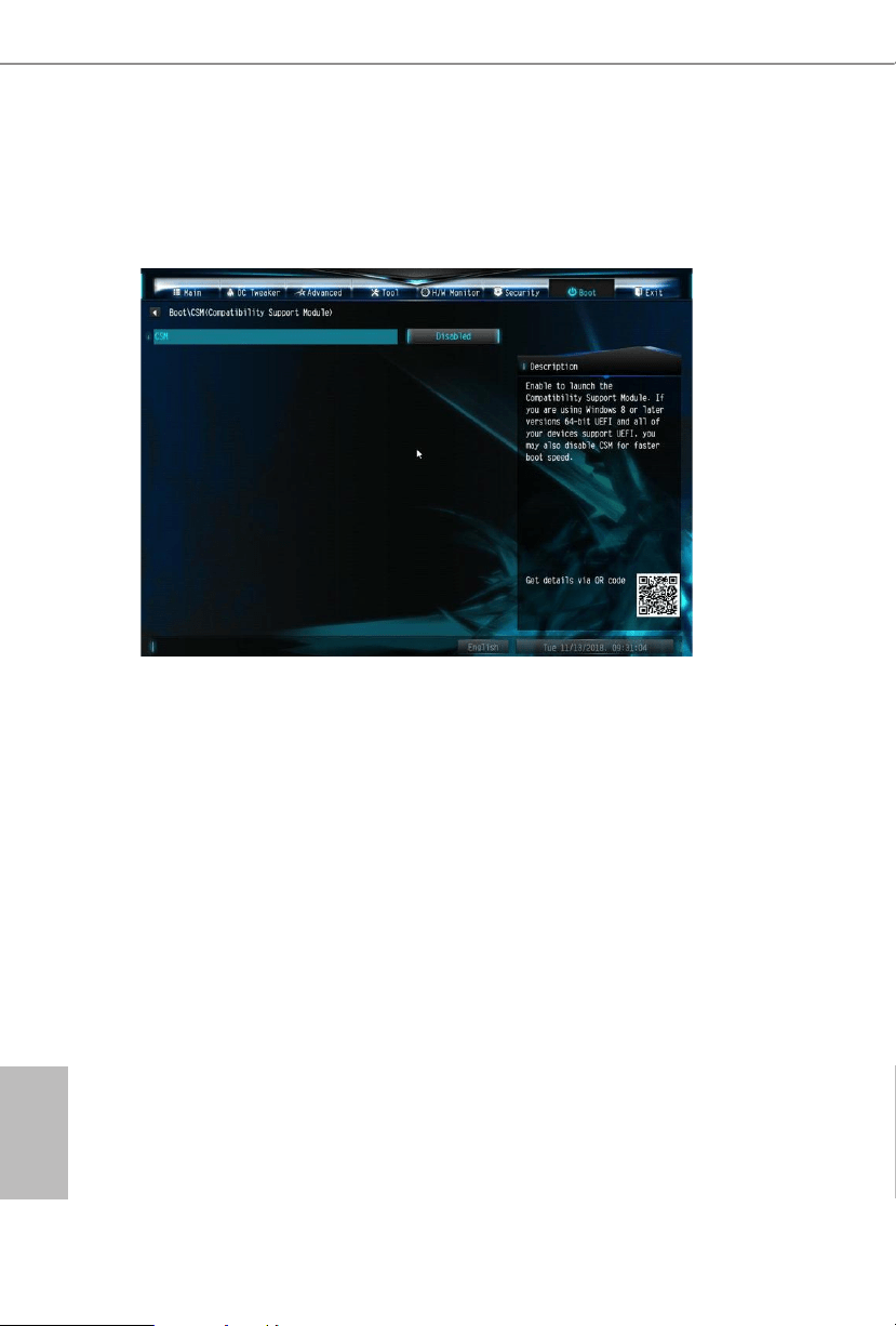
CSM (Compatibility Support Module)
CSM
Enable to launch the Compatibility Support Module. Please do not disable unless
you’re running a WHCK test.
Launch PXE OpROM Policy
Select UEFI only to run those that support UEFI option ROM only. Select Legacy
only to run those that support legacy option ROM only. Select Do not launch to not
execute both legacy and UEFI option ROM.
Launch Storage OpROM Policy
Select UEFI only to run those that support UEFI option ROM only. Select Legacy
only to run those that support legacy option ROM only. Select Do not launch to not
execute both legacy and UEFI option ROM.
A300M-STX
49
English
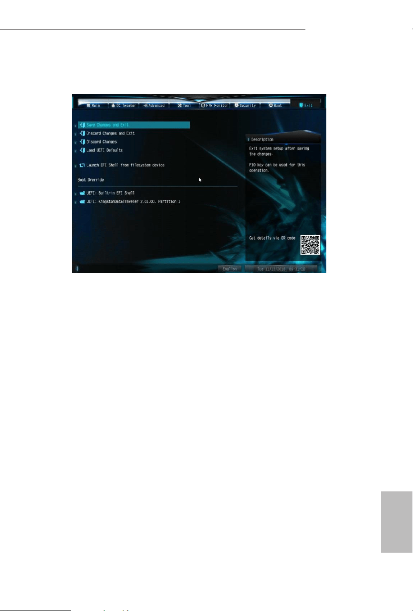
4.9 Exit Screen
Save Changes and Exit
When you select this option the following message, “Save conguration changes
and exit setup?” will pop out. Select [OK] to save changes and exit the UEFI SETUP
UTILITY.
Discard Changes and Exit
When you select this option the following message, “Discard changes and exit
setup?” will pop out. Select [OK] to exit the UEFI SETUP UTILITY without saving
any changes.
Discard Changes
When you select this option the following message, “Discard changes?” will pop
out. Select [OK] to discard all changes.
Load UEFI Defaults
Load UEFI default values for all options. e F9 key can be used for this operation.
Launch EFI Shell from lesystem device
Copy shellx64.e to the root directory to launch EFI Shell.

DECLARATION OF CONFORMITY
Per FCC Part 2 Section 2.1077(a)
Responsible Party Name: ASRock Incorporation
Address:
13848 Magnolia Ave, Chino, CA91710
+1-909-590-8308/+1-909-590-1026
Phone/FaxNo:
hereby declares that the product
Product Name : Motherboard
Model Number :
Conforms to the following specications:
FCC Part 15, Subpart B, Unintentional Radiators
Supplementary Information:
is device complies with part 15 of the FCC Rules. Operation is subject to the
following two conditions: (1) is device may not cause harmful interference,
and (2) this device must accept any interference received, including interference
that may cause undesired operation.
Representative Person’s Name:
James
Signature :
Date :
May 12, 2017
A300M-STX
EMC
—
Directive 2014/30/EU (from April 20th, 2016)
☐ EN 55022:2010/AC:2011 Class B EN 55024:2010/A1:2015
ڛ EN 55032:2012+AC:2013 Class B ڛ
ڛ
EN 61000-3-3:2013
ڛ EN 61000-3-2:2014
ڛ
LVD —Directive 2014/35/EU (from April 20th, 2016)
EN 60950-1 : 2011+ A2: 2013 ☐
☐
EN 60950-1 : 2006/A12: 2011
ڛ RoHS
—
Directive 2011/65/EU
ڛ CE marking
(EU conformity marking)
☐
EU Declaration of Conformity
For the following equipment:
Motherboard
(Product Name)
A300M-STX
(Model Designation / Trade Name)