Loading ...
Loading ...
Loading ...
10
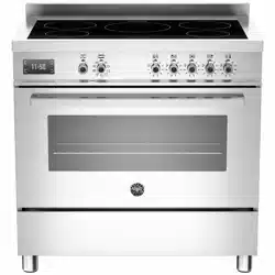
Burner "MINIMUM" adjustment:
Work surface burner adjustment: follow the instructions below to adjust the work
surface burner minimum:
- Light the burner and set the knob to the MINIMUM position (small flame).
- Remove the knob of the valve that is press-fit on the rod of that valve.
- Insert a small slotted screwdriver into the hole on the valve body (Fig.10A) and
turn the choke screw to the right or left until the burner flame is adjusted to
minimum.
- For the gas valve of dual burner the choke valve is located on the valve body
(fig. 10B) , the A screw adjust the outer ring, the B screw adjust the inner ring.
- Make sure that the flame does not go out when switching quickly from the
MAXIMUM to the MINIMUM position.
Fig 10A Fig 10B
WARNING: The above-mentioned adjustment should be made only with natural gas
burners, while those operating with liquid gas the screw must be locked at the end
in a clockwise direction.
Test the operation of It should be noted that Bertazzoni SpA cannot accept any liability for direct or
the cooker before indirect damage caused by incorrect connection or improper installation. When
leaving being repaired, the appliance must always be disconnected from the mains supply; if
required, notify our customer service.
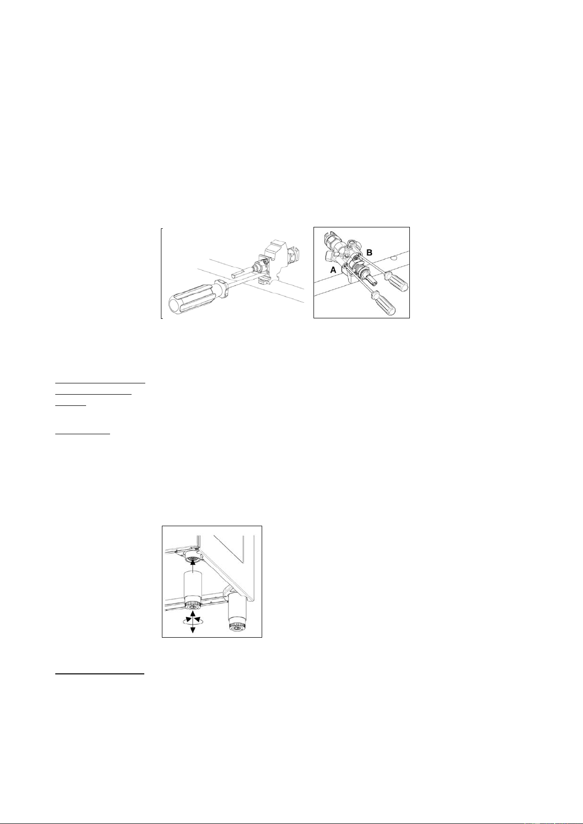
Support legs 4 support legs are supplied separately and are fitted on location to the four corners
of the lower support frame (Fig.11)
After unpacking the cooker, lift it approx 250mm to fit the legs then gently lower the
cooker to keep undue strain from the legs. It is recommended to use a lifting device
instead of tilting the unit.
Transit supports are left in situ. Each leg is firmly pushed over one of the transit
supports. If the legs are not used and the cooker is mounted onto a plinth, leave
transit legs in position to allow for clearance.
Fig 11
Up-stand Installation The up-stand is packaged at the bottom rear of the cooker. The up-stand is fixed
along the rear of the cooker hob. Screw fixing points for locating the up-stand are at
either end.
1. Place the up-stand on the rear of the hob, line up locating holes and secure with
the screws supplied.
2.
Loading ...
Loading ...
Loading ...