Home
Bookmarks
Home
Manitowoc
Manitowoc IYT1900A263E User Manual
Page 254
Manitowoc IYT1900A263E - 48" Indigo NXT Series Air Cooled Modular Ice Machine
User Manual - Page 254
For IYT1900A263E.
PDF File Manual
,
264 pages
,
Read Online
|
Download pdf file
Safety Notices
Definitions
General Information
Model Numbers
Air-Water-Remote Condenser Models
Model Nomenclature
Ice Cube Sizes
Model/Serial Number Location
Warranty
Warranty Registration
LuminIce® II
Installation
Location of Ice Machine
Clearance Requirements
Air, Water, Remote Condenser Models
Ice Machine Heat of Rejection
Installation on a Bin
Ice Machine on a Dispenser Installation
Water Supply and Drains
Line Set Applications
Remote Condenser
Remote Ice Machine Usage with Non-Manitowoc Multi-Circuit Condensers
Maintenance
Cleaning and Sanitizing
iAuCS®
Touchscreen Operation For The Clean Cycle
Starting a clean cycle
Water curtain/damper operation during the clean cycle
Pausing a clean cycle
Power interruption during clean cycle
Aborting a clean cycle
Cleaning/Sanitizing Procedure
Cleaning Procedure
Sanitizing Procedure
Preventative Maintenance Cleaning Procedure
Removal from Service/Winterization
Air-Cooled Ice Machines
Water-Cooled Ice Machines
Operation
Touch Screen Features
Home screen icon descriptions
Setup Wizard
Menu Navigation Overview
Settings Menu Screen Navigation
Operational Checks
General
Ice Thickness Check
Sequence of Operation
Self Contained Air or Water Cooled
Energized Parts Chart Self contained Air or Water-Cooled Models
Remote Condenser
Energized Parts Chart Remote Air-Cooled Condenser Models
Troubleshooting
Troubleshooting
Event Log
Event Log Detail
Thaw Cycle
Safe Operation Mode
E01 Long Freeze Cycle
E02 Long Harvest Cycle
Analyzing Why A Service Fault (E01 & E02)Stopped the Ice Machine
E01 Long Freeze
E02 Long Harvest
Troubleshooting By Symptom
Reset To Factory Defaults
Symptom #1 - Ice Machine Will Not Run
#2 - Low Production, Long Freeze Cycle
Symptom #2 - Freeze Cycle Refrigeration System Operational Analysis Tables
Symptom #3 & #4 - Harvest Problems Selfâcontained Air, Water & Remote Condenser Models
Symptom #3 - Self-Contained Air or Water-cooled
Symptom #3 - Remote Condenser
Symptom #4 - Self-Contained Air, Water-Cooled or Remote
Component Check Procedures
Electrical Components
Control Board, Display And Touchscreen
Control Board Relay Test
Programming A Replacement Control Board
USB Flash Drive Specifications and Formatting
Exporting Data to a Flash Drive
Upgrading Firmware with a Flash Drive
Main Fuse
Bin Switch
Water Level Control Circuitry
Ice Thickness Probe (Initiates Harvest)
Bin Level Probe
Thermistors
High Pressure Cutout (HPCO) Control
Fan Cycle Control
Harvest Assist Air Pump
Compressor Electrical Diagnostics
Diagnosing Start Components
Refrigeration Components
Head Pressure Control Valve
Harvest Pressure Regulating (HPR) System Remote Condenser Only
Water Regulating Valve
Refrigerant Recovery/Evacuation
Definitions
Refrigerant Re-Use Policy
Self-Contained Model Procedure
Remote Condenser Model Procedure
System Contamination Clean-Up
Determining Severity Of Contamination
Cleanup Procedure
Liquid Line Filter-Driers
Replacing Pressure Controls Without Removing Refrigerant Charge
Total System Refrigerant Charge
Self-Contained Air & Water Cooled
Remote Condenser
Charts
Cycle Times/24-Hour Ice Production/Refrigerant Pressure Charts
IF0300 Series
IT0300 Series
IT0420 Series
IT0450 Series
IT0500 Series
IF0500N
IF0600 Series
IT0620 Series
IT0750 Series
IF0900 Series
IT0900 series
IT1200 Series
IT1500 Series
IT1900 Series
Diagrams
Wiring Diagrams
Wiring Diagram Legend
IF0300/IT0420/IT0450/IT0500/IT0620/IT0750 1ph Air/Water
IT0500/IT1200 - 1ph Remote Air-Cooled
IF0600/IF0900/IT0900/IT1200 - 1ph Air/Water
IF0600/IF0900/IT0900/IT1200 - 3ph Air/Water
IT1500/IT1900 - 1ph Air/Water
IT1500/IT1900 - 3 ph Air/Water
IF0500/IF0600/IF0900/IT1200/IF1500 - 1ph Remote
IF0500/IF0600/IF0900/IT1200/IF1500 - 3ph Remote Condenser
Electronic Control Board
Electrical Noise Filter
Refrigeration Tubing Schematics
Self-Contained Air or Water-Cooled
Remote Air-Cooled Condenser Models
Page 254/264
Page 1
Page 2
Page 3
Page 4
Page 5
Page 6
Page 7
Page 8
Page 9
Page 10
Page 11
Page 12
Page 13
Page 14
Page 15
Page 16
Page 17
Page 18
Page 19
Page 20
Page 21
Page 22
Page 23
Page 24
Page 25
Page 26
Page 27
Page 28
Page 29
Page 30
Page 31
Page 32
Page 33
Page 34
Page 35
Page 36
Page 37
Page 38
Page 39
Page 40
Page 41
Page 42
Page 43
Page 44
Page 45
Page 46
Page 47
Page 48
Page 49
Page 50
Page 51
Page 52
Page 53
Page 54
Page 55
Page 56
Page 57
Page 58
Page 59
Page 60
Page 61
Page 62
Page 63
Page 64
Page 65
Page 66
Page 67
Page 68
Page 69
Page 70
Page 71
Page 72
Page 73
Page 74
Page 75
Page 76
Page 77
Page 78
Page 79
Page 80
Page 81
Page 82
Page 83
Page 84
Page 85
Page 86
Page 87
Page 88
Page 89
Page 90
Page 91
Page 92
Page 93
Page 94
Page 95
Page 96
Page 97
Page 98
Page 99
Page 100
Page 101
Page 102
Page 103
Page 104
Page 105
Page 106
Page 107
Page 108
Page 109
Page 110
Page 111
Page 112
Page 113
Page 114
Page 115
Page 116
Page 117
Page 118
Page 119
Page 120
Page 121
Page 122
Page 123
Page 124
Page 125
Page 126
Page 127
Page 128
Page 129
Page 130
Page 131
Page 132
Page 133
Page 134
Page 135
Page 136
Page 137
Page 138
Page 139
Page 140
Page 141
Page 142
Page 143
Page 144
Page 145
Page 146
Page 147
Page 148
Page 149
Page 150
Page 151
Page 152
Page 153
Page 154
Page 155
Page 156
Page 157
Page 158
Page 159
Page 160
Page 161
Page 162
Page 163
Page 164
Page 165
Page 166
Page 167
Page 168
Page 169
Page 170
Page 171
Page 172
Page 173
Page 174
Page 175
Page 176
Page 177
Page 178
Page 179
Page 180
Page 181
Page 182
Page 183
Page 184
Page 185
Page 186
Page 187
Page 188
Page 189
Page 190
Page 191
Page 192
Page 193
Page 194
Page 195
Page 196
Page 197
Page 198
Page 199
Page 200
Page 201
Page 202
Page 203
Page 204
Page 205
Page 206
Page 207
Page 208
Page 209
Page 210
Page 211
Page 212
Page 213
Page 214
Page 215
Page 216
Page 217
Page 218
Page 219
Page 220
Page 221
Page 222
Page 223
Page 224
Page 225
Page 226
Page 227
Page 228
Page 229
Page 230
Page 231
Page 232
Page 233
Page 234
Page 235
Page 236
Page 237
Page 238
Page 239
Page 240
Page 241
Page 242
Page 243
Page 244
Page 245
Page 246
Page 247
Page 248
Page 249
Page 250
Page 251
Page 252
Page 253
Page 254
Page 255
Page 256
Page 257
Page 258
Page 259
Page 260
Page 261
Page 262
Page 263
Page 264
Contents
Table of Contents
Search
Previous
Next
Troubleshooting
Bookmarks
Loading ...
Loading ...
Loading ...
254
Part Number: 000015430 Re
v 02 5/20
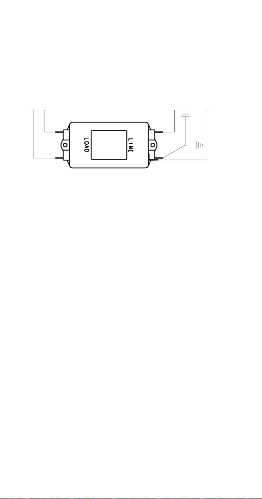
ELECTRICAL
NOISE
FIL
TER
Filter is inst
alled to the incoming line volt
age power supply
on Kor
ean models.
CONTROL BOX
FILTER
JUNCTION BOX
BLK
RED
L2
L1
BLK
RED
L2
L1
CONTROL
BOX
Loading ...
Loading ...
Loading ...
File type: PDF
File name: 79516753_irt1900a263e.pdf
File size: 5.16 MB
File Language: English
Pages: 264
Author: Manitowoc
File created: 2020-06-16
Published:
2021-08-19
Updated: 2023-06-07
Download File
Table of Contents
×
Safety Notices
3
Definitions
4
General Information
19
Model Numbers
19
Air-Water-Remote Condenser Models
19
Model Nomenclature
20
Ice Cube Sizes
21
Model/Serial Number Location
21
Warranty
22
Warranty Registration
22
LuminIce® II
23
Installation
25
Location of Ice Machine
25
Clearance Requirements
26
Air, Water, Remote Condenser Models
26
Ice Machine Heat of Rejection
27
Installation on a Bin
27
Ice Machine on a Dispenser Installation
28
Water Supply and Drains
29
Line Set Applications
30
Remote Condenser
31
Remote Ice Machine Usage with Non-Manitowoc Multi-Circuit Condensers
34
Maintenance
37
Cleaning and Sanitizing
37
iAuCS®
38
Touchscreen Operation For The Clean Cycle
39
Starting a clean cycle
39
Water curtain/damper operation during the clean cycle
39
Pausing a clean cycle
39
Power interruption during clean cycle
39
Aborting a clean cycle
39
Cleaning/Sanitizing Procedure
40
Cleaning Procedure
40
Sanitizing Procedure
45
Preventative Maintenance Cleaning Procedure
48
Removal from Service/Winterization
50
Air-Cooled Ice Machines
50
Water-Cooled Ice Machines
51
Operation
53
Touch Screen Features
53
Home screen icon descriptions
55
Setup Wizard
57
Menu Navigation Overview
58
Settings Menu Screen Navigation
58
Operational Checks
63
General
63
Ice Thickness Check
64
Sequence of Operation
66
Self Contained Air or Water Cooled
66
Energized Parts Chart Self contained Air or Water-Cooled Models
70
Remote Condenser
72
Energized Parts Chart Remote Air-Cooled Condenser Models
76
Troubleshooting
79
Troubleshooting
79
Event Log
80
Event Log Detail
81
Thaw Cycle
86
Safe Operation Mode
87
E01 Long Freeze Cycle
88
E02 Long Harvest Cycle
88
Analyzing Why A Service Fault (E01 & E02)Stopped the Ice Machine
88
E01 Long Freeze
89
E02 Long Harvest
91
Troubleshooting By Symptom
92
Reset To Factory Defaults
93
Symptom #1 - Ice Machine Will Not Run
94
#2 - Low Production, Long Freeze Cycle
97
Symptom #2 - Freeze Cycle Refrigeration System Operational Analysis Tables
99
Symptom #3 & #4 - Harvest Problems Selfâcontained Air, Water & Remote Condenser Models
127
Symptom #3 - Self-Contained Air or Water-cooled
128
Symptom #3 - Remote Condenser
130
Symptom #4 - Self-Contained Air, Water-Cooled or Remote
132
Component Check Procedures
135
Electrical Components
135
Control Board, Display And Touchscreen
135
Control Board Relay Test
138
Programming A Replacement Control Board
139
USB Flash Drive Specifications and Formatting
140
Exporting Data to a Flash Drive
141
Upgrading Firmware with a Flash Drive
142
Main Fuse
143
Bin Switch
144
Water Level Control Circuitry
147
Ice Thickness Probe (Initiates Harvest)
151
Bin Level Probe
155
Thermistors
157
High Pressure Cutout (HPCO) Control
161
Fan Cycle Control
164
Harvest Assist Air Pump
165
Compressor Electrical Diagnostics
166
Diagnosing Start Components
168
Refrigeration Components
171
Head Pressure Control Valve
171
Harvest Pressure Regulating (HPR) System Remote Condenser Only
175
Water Regulating Valve
178
Refrigerant Recovery/Evacuation
179
Definitions
179
Refrigerant Re-Use Policy
180
Self-Contained Model Procedure
182
Remote Condenser Model Procedure
186
System Contamination Clean-Up
190
Determining Severity Of Contamination
190
Cleanup Procedure
192
Liquid Line Filter-Driers
196
Replacing Pressure Controls Without Removing Refrigerant Charge
197
Total System Refrigerant Charge
198
Self-Contained Air & Water Cooled
198
Remote Condenser
199
Charts
201
Cycle Times/24-Hour Ice Production/Refrigerant Pressure Charts
201
IF0300 Series
202
IT0300 Series
204
IT0420 Series
206
IT0450 Series
208
IT0500 Series
210
IF0500N
213
IF0600 Series
214
IT0620 Series
217
IT0750 Series
219
IF0900 Series
221
IT0900 series
224
IT1200 Series
226
IT1500 Series
229
IT1900 Series
232
Diagrams
235
Wiring Diagrams
235
Wiring Diagram Legend
235
IF0300/IT0420/IT0450/IT0500/IT0620/IT0750 1ph Air/Water
236
IT0500/IT1200 - 1ph Remote Air-Cooled
238
IF0600/IF0900/IT0900/IT1200 - 1ph Air/Water
240
IF0600/IF0900/IT0900/IT1200 - 3ph Air/Water
242
IT1500/IT1900 - 1ph Air/Water
244
IT1500/IT1900 - 3 ph Air/Water
246
IF0500/IF0600/IF0900/IT1200/IF1500 - 1ph Remote
248
IF0500/IF0600/IF0900/IT1200/IF1500 - 3ph Remote Condenser
250
Electronic Control Board
252
Electrical Noise Filter
254
Refrigeration Tubing Schematics
255
Self-Contained Air or Water-Cooled
255
Remote Air-Cooled Condenser Models
259
Search:
×
Search