Bravo
®
8830/8840
Owner's Manual
Part Number
8830-999-4 AD


Corporate Headquarters
Columbia Centre III, 9525 West Bryn Mawr Avenue, Rosemont, Illinois 60018 • U.S.A.
847.288.3300 • FAX: 847.288.3703
Service phone number: 800.351.3737 (toll-free within U.S.A., Canada)
Global Website: www.cybexintl.com
International Offices
All Other EMEA Countries and Distributor Business EMEA*
Bijdorpplein 25-31
2992 LB Barendrecht
THE NETHERLANDS
Telephone: (+31) 180 646 644
United Kingdom
Life Fitness UK LTD
Queen Adelaide
Ely, Cambs, CB7 4UB
Telephone: General Office (+44) 1353.666017
Customer Support (+44) 1353.665507
AMERICAS
North America
Cybex International Inc.
Columbia Centre III
9525 West Bryn Mawr Avenue
Rosemont, IL 60018 U.S.A.
Telephone: (847) 288 3300
ASIA PACIFIC (AP)
Japan
Life Fitness Japan, Ltd
4-17-33 Minami Aoyama 1F/B1F
Minato-ku - Tokyo 107-0062
Japan
Telephone: (+81) 0120.114.482
Fax: (+81) 03-5770-5059
Germany, Austria, and Switzerland
Life Fitness Europe GMBH
Neuhofweg 9
85716 Unterschleißheim
GERMANY
Telephone:
+49 (0) 89 / 31775166 Germany
+43 (0) 1 / 6157198 Austria
+41 (0) 848 / 000901 Switzerland
Brazil
Life Fitness Brasil
Av. Rebouças, 2315
Pinheiros
São Paulo, SP 05401-300
BRAZIL
SAC: 0800 773 8282 option 2
Telephone: +55 (11) 3095 5200 option 2
Hong Kong
Life Fitness Asia Pacific LTD
32/F, Global Trade Square
21 Wong Chuk Hang Road
Hong Kong
Telephone: (+852) 2575.6262
Spain
Life Fitness IBERIA
C/Frederic Mompou 5,1º1ª
08960 Sant Just Desvern Barcelona
SPAIN
Telephone: (+34) 93.672.4660
Latin America and Caribbean*
Life Fitness, Inc.
Columbia Centre III
9525 West Bryn Mawr Avenue
Rosemont, IL 60018 U.S.A.
Telephone: (847) 288 3300
All Other Asia Pacific countries and distributor business Asia
Pacific*
32/F, Global Trade Square
21 Wong Chuk Hang Road
Hong Kong
Telephone: (+852) 2575.6262
Fax: (+852) 2575.6894
Belgium
Life Fitness Benelux NV
Parc Industrial de Petit-Rechain
4800 Verviers
BELGIUM
Telephone: (+32) 87 300 942
EUROPE, MIDDLE EAST, and AFRICA (EMEA)
Netherlands and Luxemburg
Life Fitness Atlantic BV
Bijdorpplein 25-31
2992 LB Barendrecht
THE NETHERLANDS
Telephone: (+31) 180 646 666
*Also check www.cybexintl.com for local representation or distributor/dealer
Page 3 of 27

Table of Contents
Safety
Safety Guidelines and Practices.................................................................................................5
Anchoring Equipment..................................................................................................................5
Facility Safety Precautions..........................................................................................................5
User Safety Precautions...............................................................................................................6
Warnings and Cautions................................................................................................................7
Label Placement...........................................................................................................................8
Assembly
Machine Specifications................................................................................................................9
Choosing and Preparing a Site...................................................................................................9
Environment..................................................................................................................................9
Verify parts list shown below....................................................................................................10
Tools Required............................................................................................................................11
Assembly Procedure..................................................................................................................11
Exercise
Intended Use................................................................................................................................17
Instructions..................................................................................................................................17
Maintenance
Warnings.......................................................................................................................................20
Daily Procedures.........................................................................................................................20
Weekly Procedures.....................................................................................................................21
Yearly Procedures.......................................................................................................................23
Cable Adjustment.......................................................................................................................23
Warranty
What is Covered..........................................................................................................................25
Who is Covered............................................................................................................................25
Who Pays Transportation and Insurance For Service.........................................................25
What We Will Do To Correct Covered Defects.......................................................................25
What is Not Covered...................................................................................................................25
Owner's Manual...........................................................................................................................25
Exclusive Warranty......................................................................................................................25
Changes in Warranty Not Authorized.....................................................................................25
Effects of State Laws..................................................................................................................26
Warranty Coverage.....................................................................................................................26
Cybex
®
and the Cybex logo are registered trademarks of Cybex International, Inc. Bravo
®
and its mark are registered trademarks of Cybex International, Inc.
DISCLAIMER: Cybex International, Inc. makes no representations or warranties regarding the contents of this manual. We reserve the right to revise this document
at any time or to make changes to the product described within it without notice or obligation to notify any person of such revisions or changes.
©
Copyright 2019, Cybex International, Inc.
Columbia Center III - 9525 West Bryn Mawr Ave, Rosemont, IL 60018 • 800-351-3737 • 847-288-3700 • FAX 800-216-8893
www.cybexintl.com • 8830-999-4 AD • 2019
Page 4 of 27
Safety
Safety Guidelines and Practices
TIP: Read the Owner’s Manual carefully before assembling, servicing, or using the equipment. Owner must
comply with all safety guidelines in this manual. It is also the owner’s responsibility to instruct users on the
safe and proper operation of the equipment and to properly display any and all warning labels and
instructional placards. All users should read these labels and placards before using equipment.
WARNING: Serious injury or death could occur if the following safety precautions and instructions are not
followed.
WARNING: This product can expose you to chemicals including Di-isobutyl Phthalate, which is known to the
State of California to cause birth defects or other reproductive harm, and Antimony Trioxide, which is known to
the State of California to cause cancer. For more information go to http://www.P65Warnings.ca.gov
Anchoring Equipment
Owner should not allow equipment to be used until it is properly anchored as described below.
WARNING: Anchoring equipment:
• To maximize stability and eliminate rocking, tipping, or falling over, equipment must be anchored to a
solid, level surface, utilizing all anchoring holes provided.
• Fasteners must have a minimum of 500 lbs. tensile capacity. Cybex recommends .3/8” grade 2 bolts or
better. A minimum pull force of 220 lbs/100 kgs is required for each anchor position.
• If leg frames do not contact surface, DO NOT pull down with anchors. Shim any leg or frame not in contact
with surface using flat washers.
• Due to the wide variation of flooring on which machines may be anchored or installed, consult with a
qualified and licensed contractor to ensure proper anchoring and installation.
Facility Safety Precautions
Do not allow anyone, including trainers, to use equipment in a manner other than that shown on the warning
labels and instructional placards located on every machine.
Do not install equipment on an uneven surface. The solid, level surface should not deviate more than 1/8” over a
10’ distance or as defined and required by local building and architectural codes.
It is the responsibility of the facility owner/owner of the equipment to ensure that there is appropriate clearance
around each machine to allow for safe use and passage.
In compliance with the ADA (American Disabilities Act) there must be clear floor space of at least 30 by 48 inches
and be served by an accessible route for at least one of each type of exercise equipment. If the clear space is
enclosed on three sides (e.g., by walls or the equipment itself), the clear space must be 36 by 48 inches.
All other machines must have a clear floor space of 23” for all access point on the machine, unless shown in the
Owner’s Manual.
The dimensions stated in the assembly instructions of this manual include the maximum foot print (in use)
dimensions.
All equipment should be used in a supervised, access-controlled area.
Do not allow equipment to be used by children 12 and under. Supervise disabled and children 13 and older.
The owner should ensure that regular inspection and maintenance checks as detailed in this manual are performed.
Keep a log of all maintenance and repair activities.
Page 5 of 27

Each day before use, the owner should inspect the equipment. If there are any loose or worn components such
as belts, cables, grips, pulleys, or any missing, damaged labels, or placards, the owner should fix any deficiencies
before they allow the equipment to be used.
Use only Cybex components to maintain and repair the equipment.
Display the Facility Safety Sign so it is visible and prominent.
User Safety Precautions
Owners must instruct users to DO the following:
• Follow all warning labels and instructional placards when using equipment.
• Insert weight pin completely before using selectorized equipment.
• Consult a physician prior to commencing an exercise program. If at any time during exercise you feel faint, dizzy
or experience pain, stop and consult your physician.
• Use a spotter for Free Weight equipment.
Owners must instruct users to NOT DO the following:
• DO NOT pin weights on selectorized equipment in an elevated position or use the machine if found in this
position
• DO NOT increase weight resistance on equipment by any means other than those provided by Cybex.
• DO NOT wear loose or dangling clothing or jewelry while using equipment. Stay clear of moving parts.
• DO NOT lean or pull on machine
• DO NOT use machine for support during stretching.
• DO NOT attach resistance straps, ropes or other means to equipment, except those provided by the manufacturer
for intended use on the equipment.
• DO NOT exceed the maximum specified user weight.
• DO NOT use if equipment appears damaged or inoperable upon inspection
• DO NOT use if guards are missing or damaged.
• DO NOT remove any labeling from equipment.
Page 6 of 27
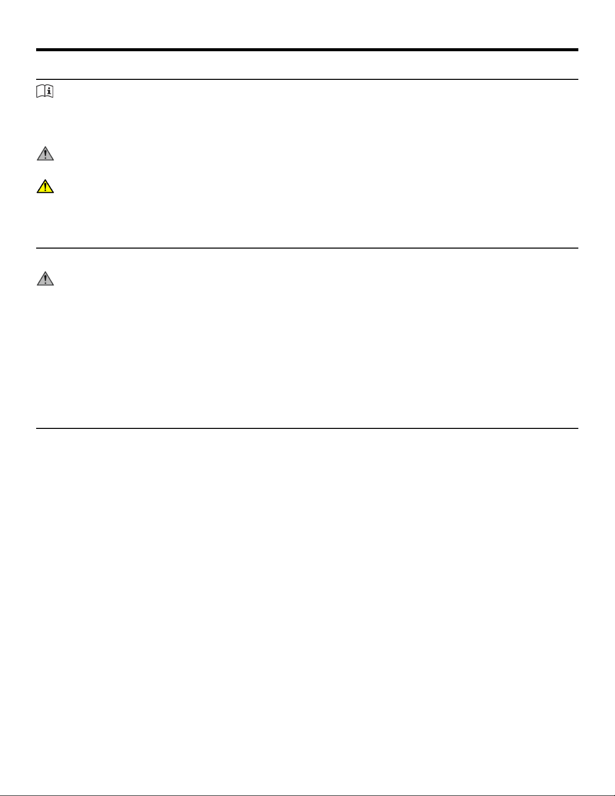
Warnings and Cautions
Warning labels indicate a potentially hazardous situation that could result in serious injury or death if the precautions
are not observed.
Caution labels indicate a potentially hazardous situation that could result in serious injury or damage to machine
if the precautions are not observed.
Contact Customer Support Services to replace any worn or damaged labels.
Page 7 of 27
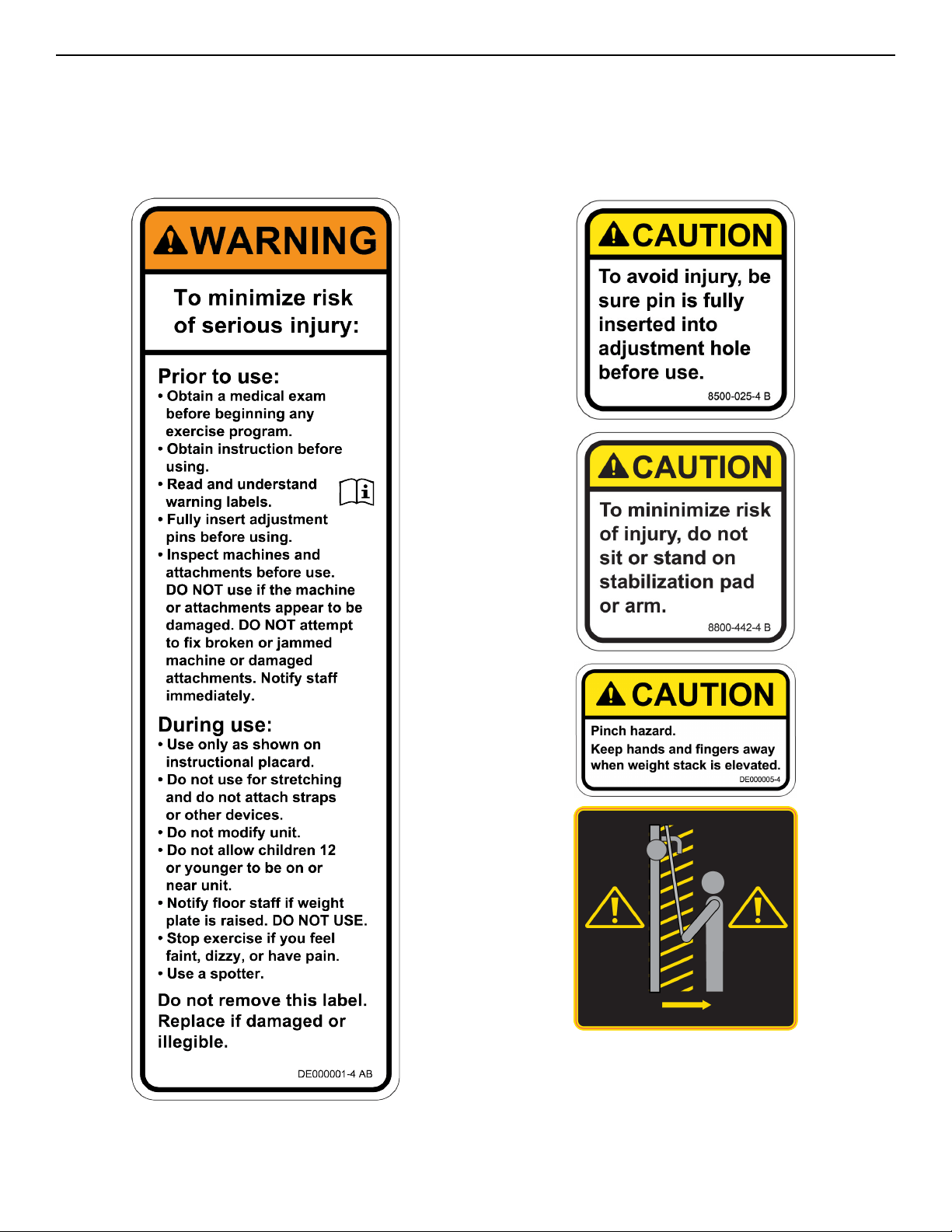
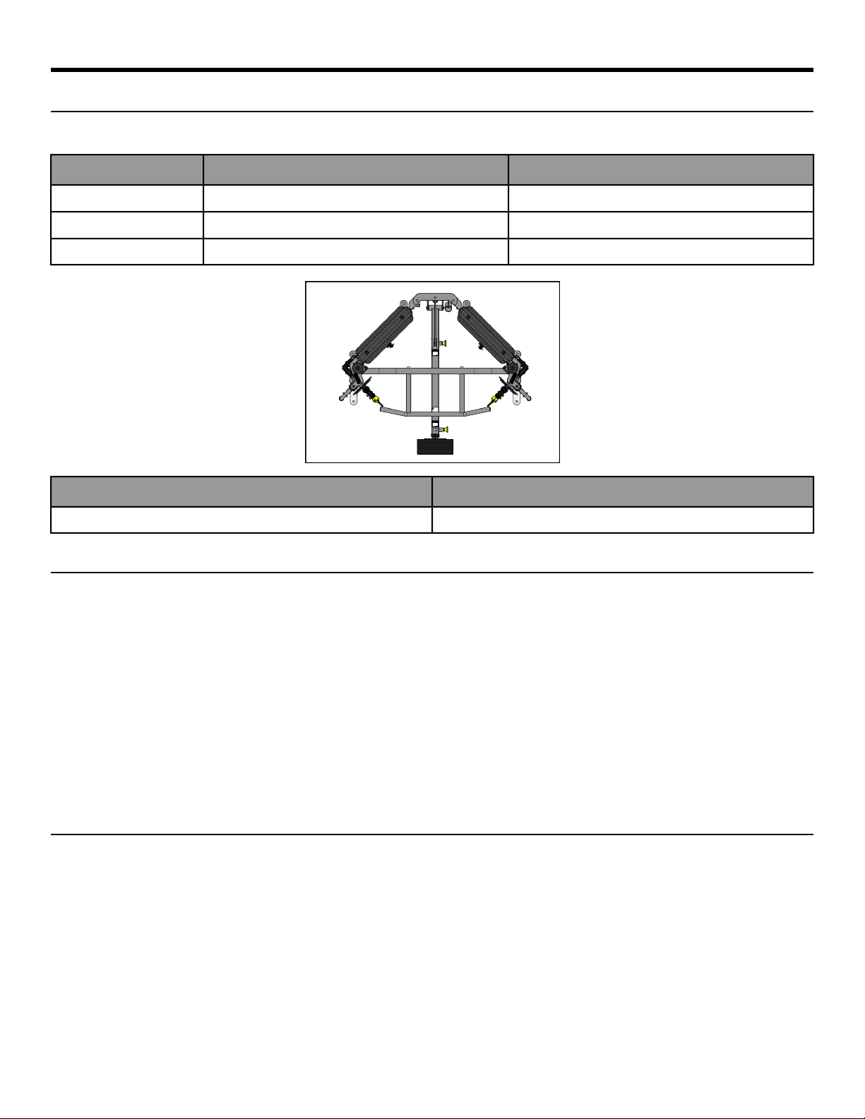
Label Placement
The following diagram shows where each label is located.
QtyDescriptionItem
1DE000001-X1
2DE000005-X2
88500-025-X3
18800-442-X4
21011940-00015
Page 8 of 27
Assembly
Machine Specifications
Total Weight and Size: 8830/8840 Bravo
8840 At Use And At Rest8830 At Use And At RestDimensions/Weight
45” L 54” W x 87” H45” L 54” W x 77” HL x W x H
114 cm L x 137 cm W x 221 cm H114 cm L x 137 cm W x 196 cm HL x W x H
901 lbs (407 kg)866 lbs (393 kg)Machine Weight
Maximum Training WeightMaximum User Weight
660 lbs/299 kg300 lbs/135kg
Choosing and Preparing a Site
Before assembling the unit, verify the chosen site meets the following criteria:
• Area is well lit and well ventilated.
• Surface is structurally sound and properly leveled.
• Free area for access to unit and emergency dismount. Minimum clearance is 23.6 inches (0.6 meters).
• Adjacent units may share the free area.
It is the responsibility of the facility owner/owner of the equipment to ensure that there is appropriate clearance
around each machine to allow for safe use and passage.
In compliance with the ADA (American Disabilities Act) there must be clear floor space of at least 30 by 48 inches
and be served by an accessible route for at least one of each type of exercise equipment. If the clear space is
enclosed on three sides (e.g., by walls or the equipment itself), the clear space must be 36 by 48 inches.
All other machines must have a clear floor space of 23” for all access point on the machine, unless shown in the
Owner’s Manual.
Environment
Humidity and Static Electricity
The unit is designed to function normally in an environment with a relative humidity range of 30% to 75%. The
unit can be shipped and stored in a relative humidity range of 10% to 90%.
Climatic dry air may cause static electricity. During workout, user may experience a shock due to build up of static
electricity on the body and the discharge path of the unit. If static electricity is experienced, increase humidity to
a comfortable level through the use of a humidifier.
Do not install, use or store the unit in an area of high humidity, such as in the vicinity of a steam room, sauna,
indoor pool or outdoors. Exposure to extensive water vapor, chlorine and/or bromine could adversely affect other
parts of the unit.
Page 9 of 27
Temperature
The unit is designed to function normally in an environment with an ambient temperature range of 50° F (10° C)
to 104° F (40° C). The unit can be shipped and stored in an environment with an ambient temperature range of 32°
F (0° C) to 140° F (60° C).
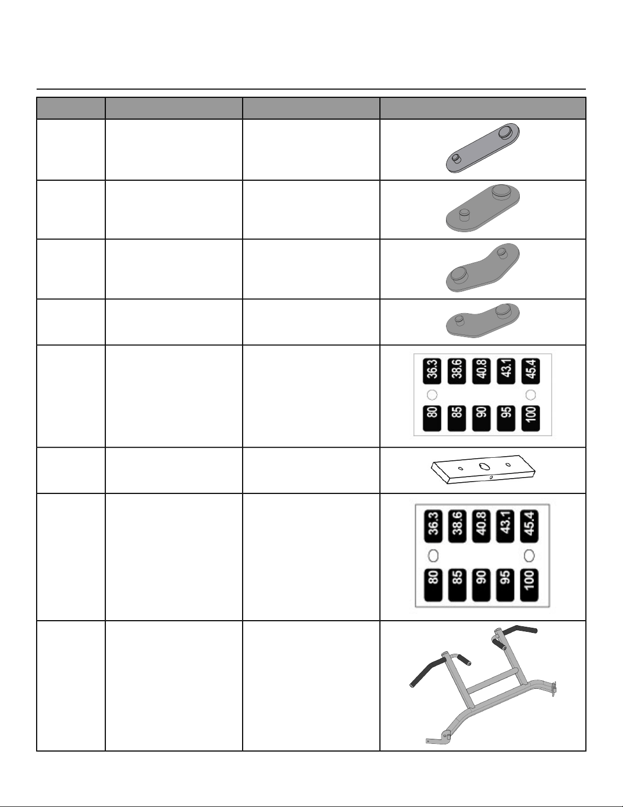
Verify parts list shown below
DiagramDescriptionPart NumberQty
Foot Pad 6.25” × 2.00”12090-3222
Foot Pad 5.00” × 2.00”13000-3532
Foot Pad13000-3541
Foot Pad13000-3551
Decal, Standard 2.5-37.5
(Included with weight pack)
DE0000131
Weight Plate (standard stack)
(Included with weight pack
13000-038)
4700-33716
Decal, Standard 40-50 (Included
with weight pack 1300-038)
DE0000141
8810 Chin Up Bar8810-1011
Page 10 of 27
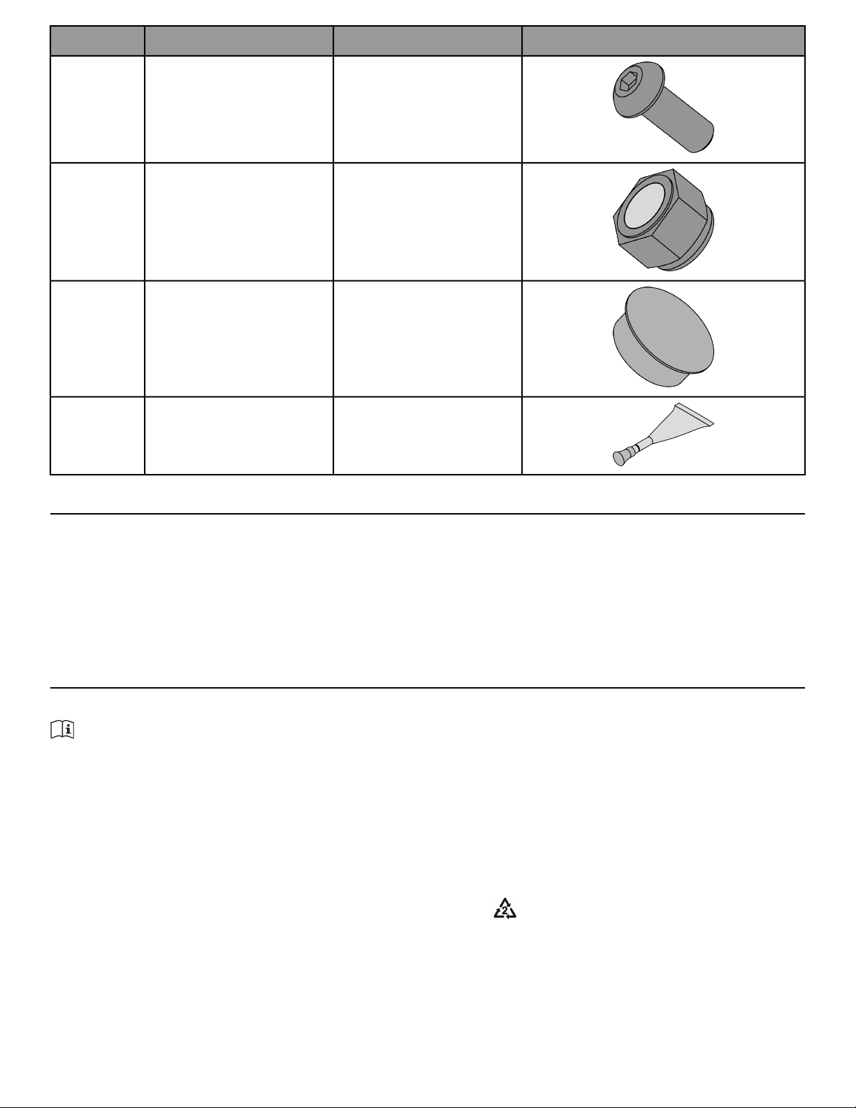
DiagramDescriptionPart NumberQty
BHSCS .375-16 × 1.00 (Included
with 8810-101)
HC7004174
Locknut .375-16, Nylon (Included
with 8810-101)
HN7049012
Insert, Plastic 1.00 Dia-11G
(Included with 8810-101)
PN6602002
Loctite #242 (Included with
8810-101)
YA0002011
Tools Required
• 9/16" Wrench
• 7/32” Allen wrench
• 3/4” Socket wrench
• Hammer
• 3/16” Pin punch
• Loctite
®
#242
Assembly Procedure
Two people will be required for this procedure.
TIP: Read and understand all instructions thoroughly before assembling this unit. Check all items carefully.
If there is damage, see the Customer Service section of this manual for proper procedure to return, replace,
or reorder parts.
If machine CAN fit through doorway
Two people will be required for this procedure
1. Move to desired location.
2. Remove shipping cones using a 3/4” socket or wrench.
3.
Remove bolt from shipping cone with hammer. Recycle cone.
4. Attach foot pads to each foot of frame.
5. If weight stack needs to be installed, follow procedure for installing weight plates and weight plate decal.
Page 11 of 27
Securely anchor machine to floor
Owner should not allow equipment to be used until it is properly anchored as described below.
WARNING: Anchoring equipment:
• To maximize stability and eliminate rocking, tipping, or falling over, equipment must be anchored to a
solid, level surface, utilizing all anchoring holes provided.
• Fasteners must have a minimum of 500 lbs. tensile capacity. Cybex recommends .3/8” grade 2 bolts or
better. A minimum pull force of 220 lbs/100 kgs is required for each anchor position.
• If leg frames do not contact surface, DO NOT pull down with anchors. Shim any leg or frame not in contact
with surface using flat washers.
• Due to the wide variation of flooring on which machines may be anchored or installed, consult with a
qualified and licensed contractor to ensure proper anchoring and installation.
Verify proper operation
If machine CANNOT fit through doorway
Two people will be required for this procedure
1. Remove shipping cones using a 3/4” socket or wrench.
2.
Remove bolt from shipping cone with hammer. Recycle cone.
3. Attach foot pads to each foot of frame.
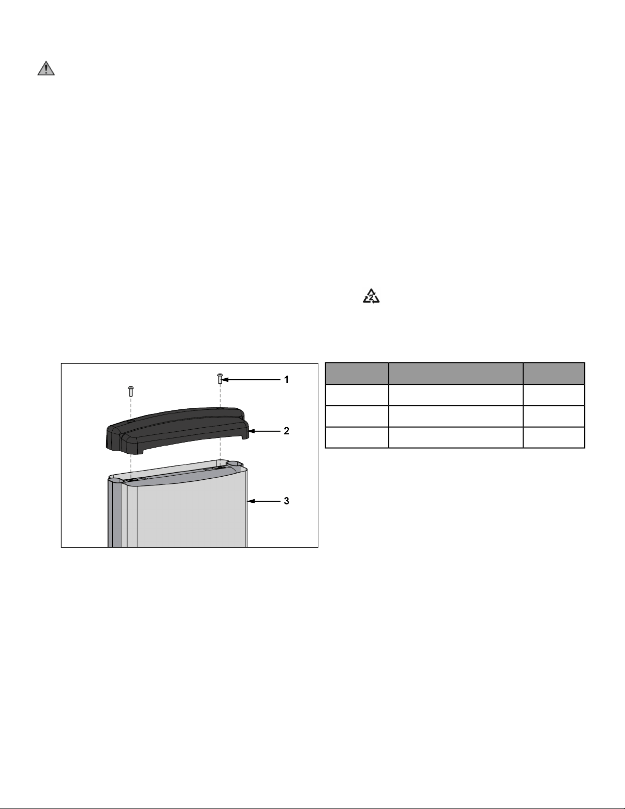
4. Remove the two Button Head Socket Cap Screws (BHSCS) securing the top cap to the frame using a 7/32”
Allen wrench.
Qty.DescriptionItem
2BHSCS1
1Top cap2
1Back panel3
5. Remove back panel from machine.
6. Verify weight stack pin is disengaged.
Page 12 of 27
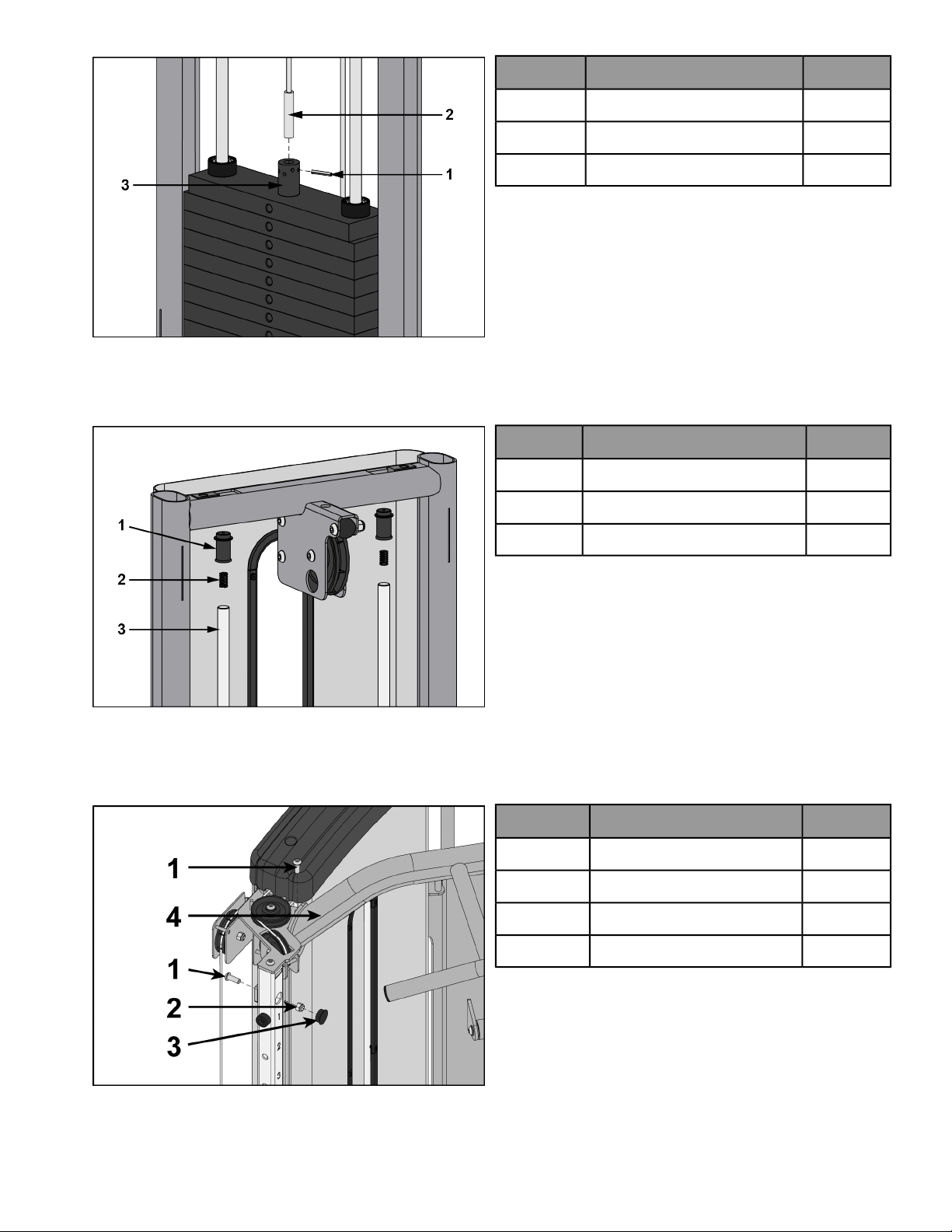
7. Remove spiral pin securing cable end to top weight using a 3/16” pin punch and hammer.
Qty.DescriptionItem
1Spiral pin1
1Cable2
1Top weight connector3
8. Remove guide rod caps. Guide rod cap contains a compression spring that will fly if grasp is not released
slowly. Slide spring loaded guide rod cap down guide rod until cap is clear of frame. Slowly release grasp of
guide rod cap and remove.
Qty.DescriptionItem
2Guide rod cap1
2Compression spring2
2Guide rod3
9. Remove lifting post.
10. Remove weight plates.
11. Remove screws securing Chin-Up Bar to frame using a 7/32" Allen wrench and a 9/16" wrench.
QtyDescriptionItem
2Screw1
1Locknut2
1Insert plug3
1Chin-Up Bar4
Page 13 of 27
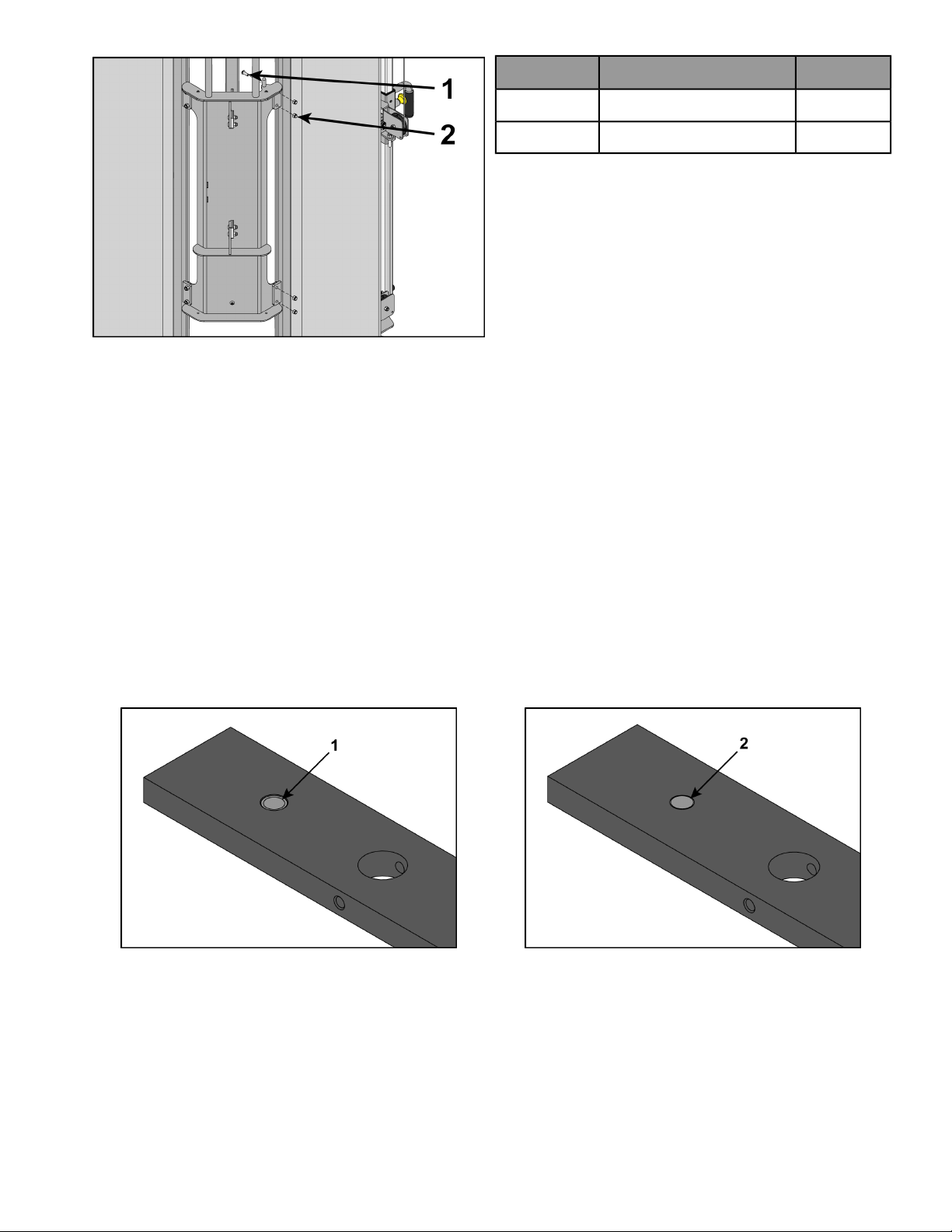
12. Remove the four BHSCS securing one of the halves.
QtyDescriptionItem
4Screw1
4Locknut2
13. Move machine to desired location.
14. Reattach the frame halves and securely tighten the four BHSCS.
15. Reattach Chin-Up Bar. Add Loctite #242 to each BHSCS and threaded holes. Tighten screws securely. Reattach
insert plugs.
Install weight plates
1. Lean guide rods slightly outward, away from machine, DO NOT put excessive pressure on guide rods, it will
damage lower guide rod caps.
2. Wipe the entire length of the guide rods with a clean cloth.
3. Lubricate the guide rods with a light coating of medium weight oil.
4. Install each weight plate, one at a time, so wide edge of bushing faces upward (1) and narrow edge of bushing
(2) faces downward.
Incorrect: Narrow bushing edge downward.Correct: Wide bushing edge upward
5. Install lifting post.
6. Install compression spring and top guide rod cap onto guide rod. Slide spring loaded top guide rod cap down
guide rod until cap is clear of guide rod plate and install. Repeat for opposite side.
Apply weight plate decal
1. Peel off half of backing from weight plate decals, making sure that the decals remain attached to the front
sheet.
Page 14 of 27
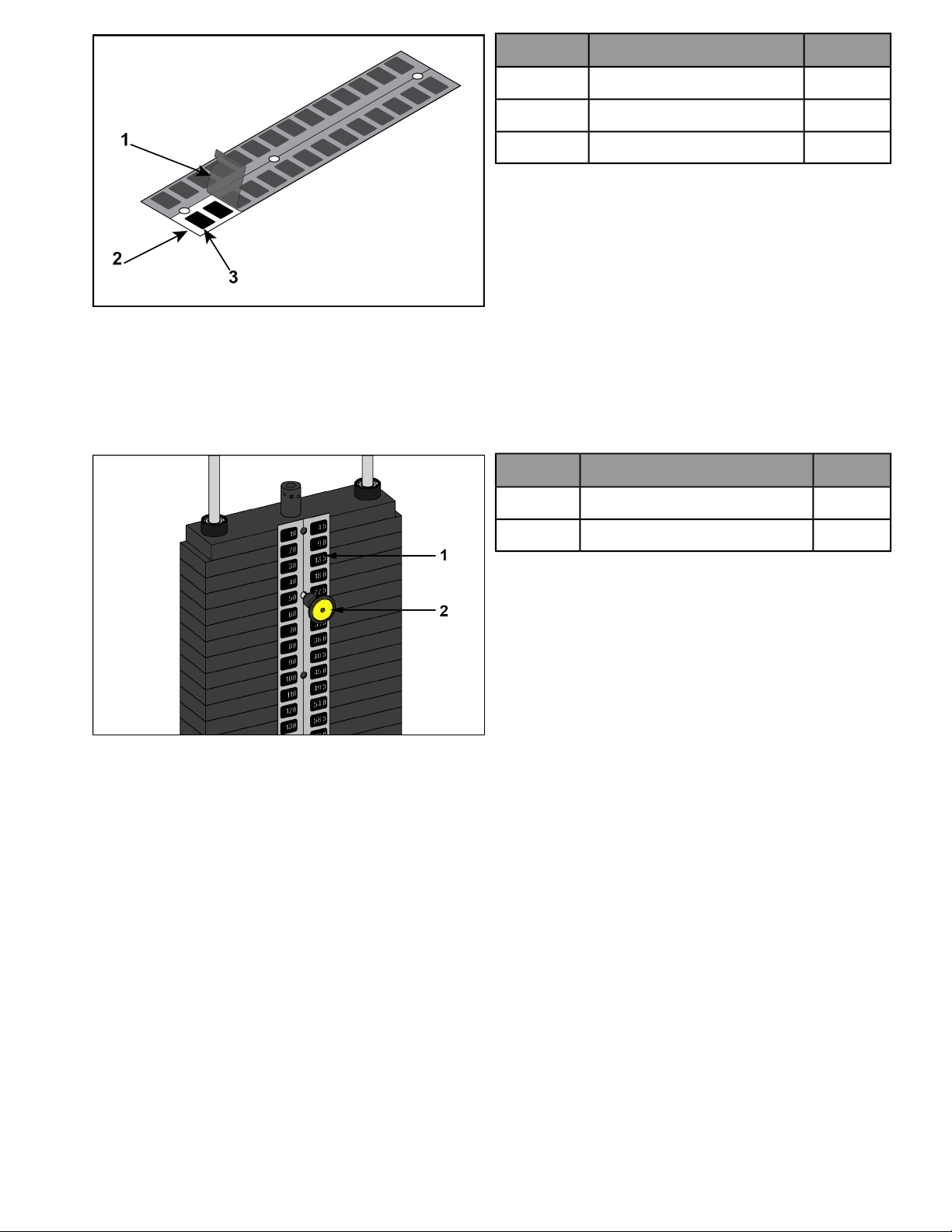
QtyDescriptionItem
1Backing1
1Front sheet2
1Weight decals3
2. Place decals front sheet in the correct position on weight plates.
3. Insert a guide pin through each hole of the decals front sheet. A guide pin can be anything that fits through
the weight stack hole, such as a weight stack selector pin.
4. Align decals and rub them onto weight plates.
5. Remove front sheet, do not peel decals off of weight plates.
QtyDescriptionItem
1Weight plate decal1
1Weight stack selector pin2
6. Repeat above steps for other half of the weight plate decals.
Page 15 of 27
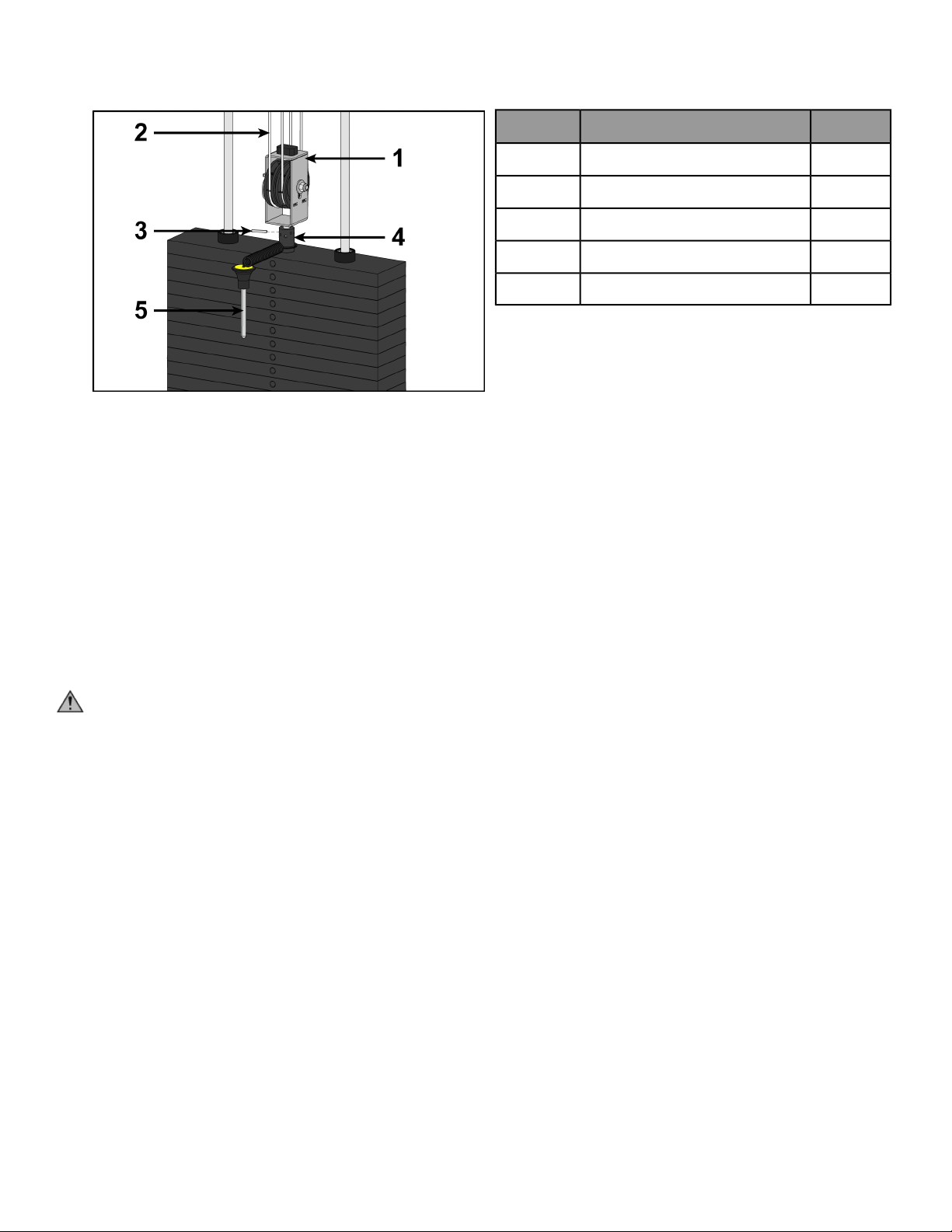
Cable routing
1. Verify cable is routed through top of pulley bracket and then route cable end to top weight connector.
2. Pull cable tight and secure in place with spiral pin using a 3/16” pin punch and a hammer.
QtyDescriptionItem
1Pulley bracket1
2Cable2
1Top weight connector3
1Roll pin4
1Weight selector pin5
3. Place weight stack pin in each plate to verify proper installation.
4. Lift top weight up and down simulating normal operation (without selecting any resistance).
5. Verify that the cable is moving smoothly and is routed straight from the pulley bracket to the top of the weight
plate connector.
Install back panel
1. Place back panel into position.
2. Secure top cap in place using two BHSCS and 7/32” Allen wrench.
Securely anchor machine to floor
Owner should not allow equipment to be used until it is properly anchored as described below.
WARNING: Anchoring equipment:
• To maximize stability and eliminate rocking, tipping, or falling over, equipment must be anchored to a
solid, level surface, utilizing all anchoring holes provided.
• Fasteners must have a minimum of 500 lbs. tensile capacity. Cybex recommends .3/8” grade 2 bolts or
better. A minimum pull force of 220 lbs/100 kgs is required for each anchor position.
• If leg frames do not contact surface, DO NOT pull down with anchors. Shim any leg or frame not in contact
with surface using flat washers.
• Due to the wide variation of flooring on which machines may be anchored or installed, consult with a
qualified and licensed contractor to ensure proper anchoring and installation.
Verify proper operation
Page 16 of 27
Exercise
Intended Use
The intended commercial use of this machine is to aid exercise and improve general physical fitness.
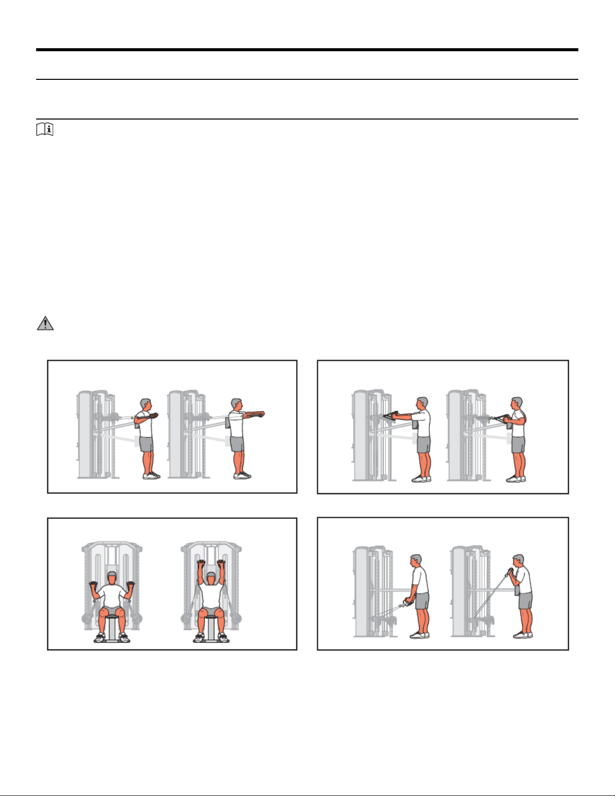
Instructions
TIP: Read and understand all instructions and warnings prior to using this machine in the Safety section of
the Owner’s Manual.
Set Up
1. Select appropriate resistance.
2. Adjust handles for proper pulley height.
3. Rotate pulleys to desired angle.
4. Adjust stabilization arm to desired angle.
5. Adjust stabilization pad to desired position.
6. Ensure all adjustment knobs are locked into place.
7. Position stabilization arm and pad all the way in and all the way down when finished.
CAUTION: Use only in manner depicted. To avoid serious injury, use equipment only as describe in placards
located on each machine.
RowChest Press
Arm CurlSeated Press
Page 17 of 27
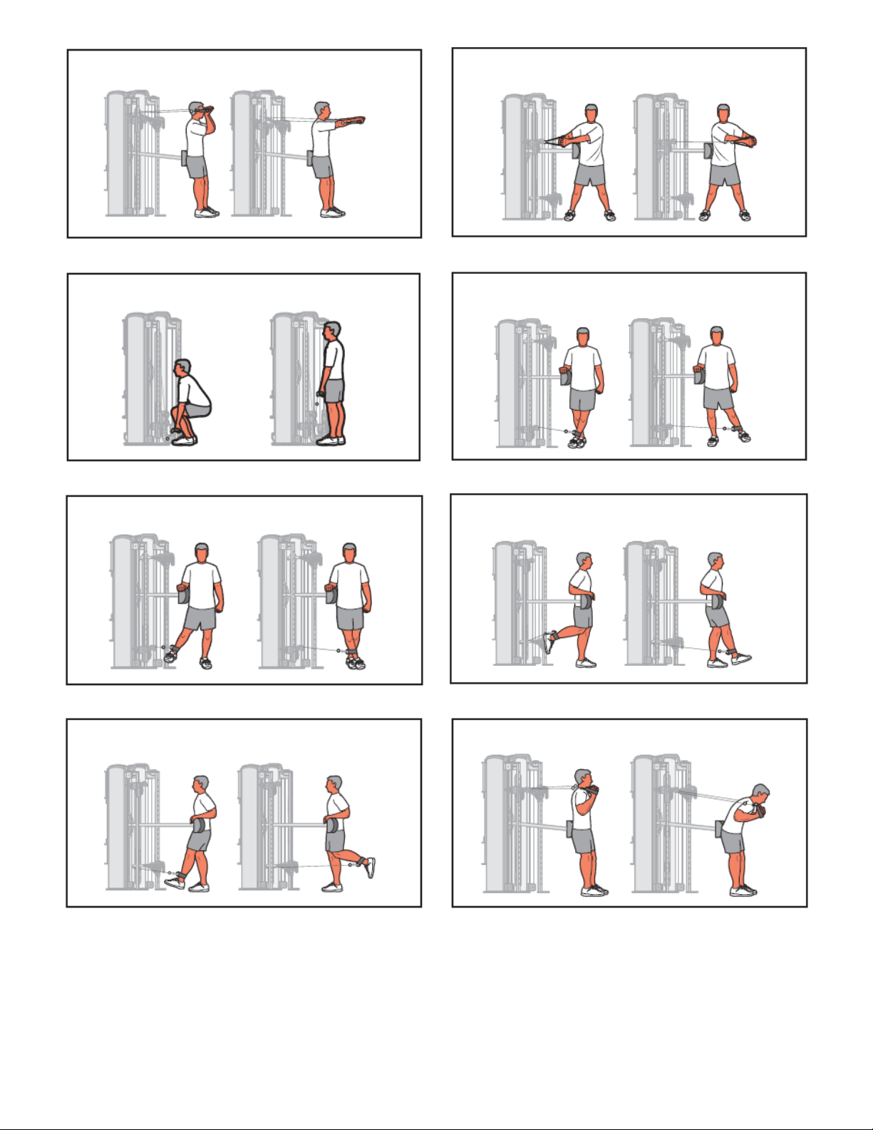
Trunk RotationArm Extension
Hip AbductionSquat
Hip FlexionHip Adduction
Trunk FlexionHip Extension
Page 18 of 27
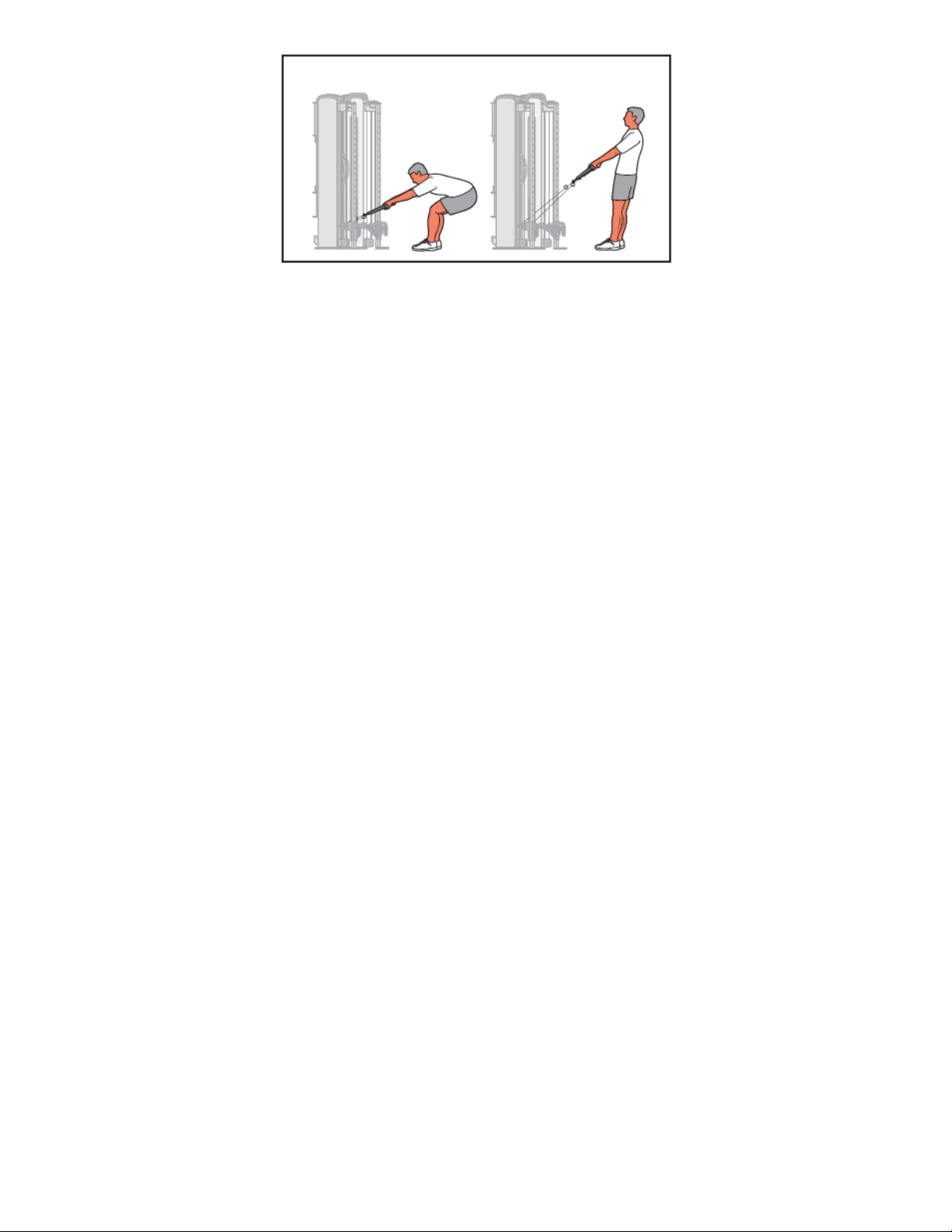
Trunk Extension
Page 19 of 27
Maintenance
All preventive maintenance activities must be performed on a regular basis. Performing routine preventive
maintenance actions can aid in providing safe, trouble-free operation of all Cybex equipment.
Cybex is not responsible for performing regular inspection and maintenance actions for your machines. Instruct
all personnel in equipment inspection and maintenance actions and also in accident reporting and recording.
Cybex representatives are available to answer any questions that you may have.
Warnings
TIP: Read all warnings in this chapter.
WARNING: For maintenance, service and repair:
• Must be performed by trained service personnel only
• Use only Cybex replacement parts.
WARNING: Equipment hazard. To avoid serious injury or death replace worn or damaged components
immediately and keep the equipment out of use until repair is completed.
WARNING: The safety level of the equipment can be maintained only if the equipment is examined regularly
for damage and wear.
Daily Procedures
When using strong cleaning agents such as rubbing alcohol or bleach, it is advisable to test first in an inconspicuous
area. Other cleaning agents may contain harsh or unknown solvents and are subject to formula changes by the
product manufacturer without notice. Should you desire to use other cleaning agents, carefully try them in an
inconspicuous area to determine potential damage to the material. Never use harsh solvents or cleaners which
are intended for industrial applications. To clean stained or soiled areas, a soft white cloth is recommended. Avoid
use of paper towels.
Cleaning products may be harmful/irritating to your skin, eyes, etc. Use protective gloves and eye protection. Do
Not inhale or swallow any cleaning product. Protect surrounding area/clothing from exposure. Use in well ventilated
area. Follow all product manufacturer’s warnings. Cybex and its vendors cannot be held responsible for damage
or injuries resulting from the use or misuse of cleaning products.
Clean Upholstery
ThenIf
1. Prepare a solution of 10% household liquid soap and warm water.
2. Apply with a soft damp cloth.
3. If necessary, apply a solution of liquid cleanser with a soft bristle brush.
4. Dampen a clean soft cloth in water and wipe residue away.
Light Soiling
1. Prepare a solution of 10% household bleach (sodium hypochlorite) and 90% water. Dampen a soft white
cloth in the solution.
2. Rub gently on the stained area.
3. Dampen a clean soft cloth in water and rinse area.
4. If stains are still present, a full strength household bleach may be used. Allow bleach to puddle on the
affected area or apply with a bleached-soaked cloth for approximately 30 minutes. Dampen a clean soft
cloth in water, and rinse area to remove any remaining bleach concentration.
More Difficult Stains
Page 20 of 27

ThenIf
1. Dampen a soft white cloth with rubbing alcohol.
2. Gently rub stained area.
3. Dampen a clean soft cloth in water and rinse area.
More Difficult Stains
(Alternative Method)
1. Apply a light coat of furniture wax for 30 seconds.
2. Lightly rub area using a clean white cloth.
Restoring Luster
Clean Frames
Wipe down all frames using a mild solution of warm water and car wash soap. Be sure to dry thoroughly. AVOID
acid or chlorine based cleaners and also cleaners containing abrasives as these could scratch or damage the
equipment.
Clean Chrome
Clean chrome tubes, first using chrome polish and then using a car wax seal. Neutral cleaners with a pH between
5.5 and 8.5 are recommended. Be sure to dry thoroughly. AVOID acid or chlorine based cleaners and also cleaners
containing abrasives as these could scratch or damage the equipment.
Guidelines for cleaning front panel:
Use clean soft cloths or sponges for application of cleaners and again for washing and rinsing. Follow up each
application with warm water rinse.
• DO NOT use abrasives or high alkaline cleaners.
• DO NOT leave cleaners on for long periods, wash immediately.
• DO NOT apply cleaners in direct sunlight or at elevated temperatures.
• DO NOT use scrapers, squeegees, or razors.
• DO NOT clean with gasoline.
Compatible Cleaners and Detergents:
• Formula 409
• Top Job
• Joy
• Palmolive
• Windex with Ammonia D
To Minimize Fine or Hairline Scratches:
Mild automotive polish applied and removed with a soft clean cloth will help fill scratches.
Suggested Polishes:
• Johnson Paste Wax
• Mirror Glaze #10 Plastic Polish (by Mirror Bright Polish Co.)
• Novus Plastics Polish #1, #2 (By Novus Inc.)
Weekly Procedures
Inspect All Nuts and Bolts
Tighten all loose nuts and bolts as required.
WARNING: Equipment hazard. To avoid serious injury or death replace worn or damaged components
immediately and keep the equipment out of use until repair is completed.
Inspect Cables
Inspect all cables for wear or damage and proper tension. When inspecting cables, run fingers on the cable, paying
particular attention to bends and attachment points.
Page 21 of 27
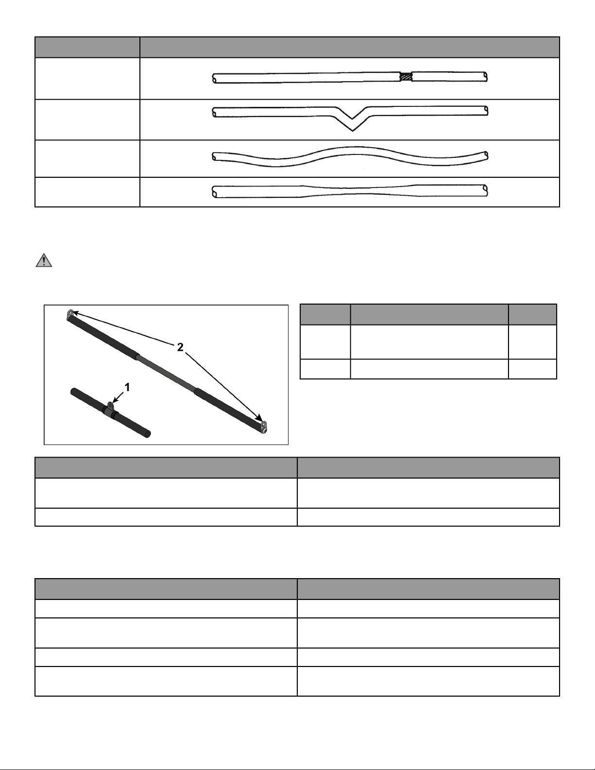
The following conditions may indicate a worn cable:
DiagramCondition of Cable
A tear or crack in the cable
sheath that exposes the
cable
A kink in the cable
A curled sheath
Necking - A stretched
cable sheath
Bars and Handles
Inspect bars and handles for wear, paying particular attention to tab area connection points.
CAUTION: Worn handles
• Do not use handles if less then 1/8” of material remains on edge.
• Replace all worn handles immediately.
QtyDescriptionItem
1
Attachment hole (Straight
handle)
1
2Attachment hole (Lat bar)2
ActionInspection
Replace all worn handles immediately.
Inspect bars and handles for wear, paying particular attention to
tab area connection points.
Replace all worn snap links immediately.Inspect snap links for proper latching (indicates wear).
Inspect Other Items
Inspect other items for proper operation, damage, or wear.
ActionInspection
Replace all loose or worn grips immediately.Inspect grips for looseness or wear.
Replace all worn labeling immediately.
Inspect all labeling for readability, including instructional placards,
warning and caution decals.
Correct all improper alignment and operation issues immediately.Inspect all weight stacks for proper alignment and operation.
Wipe Weight Stack Guide Rods clean over entire length. Lubricate
with a light coat of medium weight automotive engine oil.
Inspect guide rods for lubrication.
Page 22 of 27
Yearly Procedures
Replace all cables and belts annually
Cable Adjustment
Tools Required
• 9/16" Wrench (2)
• Hammer
• 3/16” Pin punch
Four types of cable tension adjustment are used on Cybex Strength Systems:
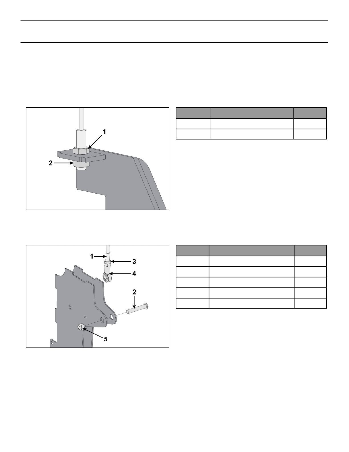
Jam Nut Adjustment
This type of adjustment uses a jam nut and a tension adjustment nut at the cable cam end as the primary
adjustment. The other end of the cable usually contains a roll pin adjustment.
Qty.DescriptionItem
1Jam nut1
1Tension adjustment nut2
Rod End Adjustment
This type of adjustment uses a socket head cap screw (SHCS) securing a cable rod end bearing to the machine.
Primary adjustment is by turning the rod end bearing. The other end of the cable usually contains a roll pin cable
adjustment.
Qty.DescriptionItem
1Cable end1
1SHCS2
1Jam nut3
1Cable rod end bearing4
1Nylon locknut5
Roll Pin Adjustment
This type of adjustment uses a roll pin and series of holes in the weight stack top weight connector.
Page 23 of 27
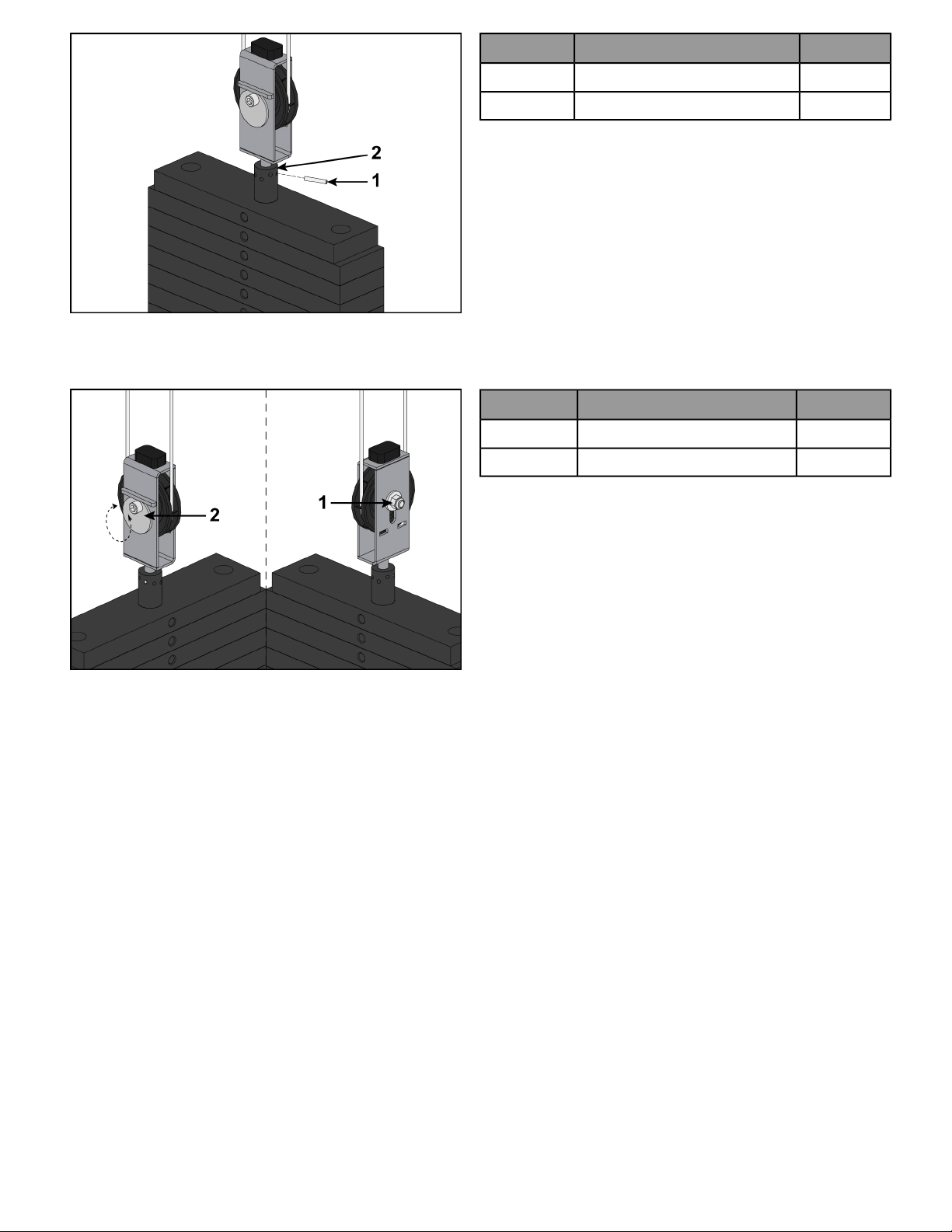
Qty.DescriptionItem
1Roll pin1
1Top weight connector2
Cam End Adjustment
This type of adjustment uses an adjustment bolt on the pulley bracket. Loosen nut and rotate cam bolt to adjust
cable.
Qty.DescriptionItem
1Nut1
1Cam bolt adjustment2
Page 24 of 27

Warranty
What is Covered
This CYBEX commercial exercise equipment product is warranted to be free of all defects in material and
workmanship.
Who is Covered
The original purchaser or any person receiving the product as a gift from the original purchaser.
Who Pays Transportation and Insurance For Service
If the Product or any covered part must be returned to a service facility for repairs, We, Cybex, will pay all
transportation and insurance charges for the first year. You are responsible for transportation and insurance charge
after the first year.
What We Will Do To Correct Covered Defects
We will ship to you any new or rebuilt replacement part or component, or at our option, replace the Product. Such
replacement parts are warranted for the remaining portion of the original warranty period.
What is Not Covered
Any failures or damage caused by unauthorized service, misuse, accident, negligence, improper assembly or
installation, debris resulting from any construction activities in the Product’s environment, rust or corrosion as a
result of the Product’s location, alterations or modifications without our written authorization, or by failure on
your part to use, operate and maintain the Product as set out in your Operation Manual.
All terms of this warranty are void if this product is moved beyond the continental borders of the United States of
America (excluding Alaska, Hawaii and Canada) and are then subject to the terms provided by that country’s
local authorizedCybex representative.
Owner's Manual
It is VERY IMPORTANT THAT YOU READ THIS MANUAL before operating the Product. Remember to perform the
periodic maintenance requirements specified in the Manual to assure proper operation and your continued
satisfaction.
Exclusive Warranty
THIS LIMITED WARRANTY IS IN LIEU OF ALL OTHER WARRANTIES OF ANY KIND EITHER EXPRESSED OR IMPLIED,
INCLUDING BUT NOT LIMITED TO THEIMPLIED WARRANTIES OF MERCHANTABILITY AND FITNESS FOR A PARTICULAR
PURPOSE, AND ALL OTHER OBLIGATIONS OR LIABILITIES ON OUR PART. We neither assume nor authorize any
person to assure for us any other obligation or liability concerning the sale of this Product. Under no circumstances
shall we be liable under this warranty, or otherwise, of any damage to any person or property, including any lost
profits or lost savings, for any special, indirect, secondary, incidental or consequential damages of any nature
arising out of the use of or inability to use this Product. Some states do not allow the exclusion or limitation of
implied warranties or of liability for incidental or consequential damages, so the above limitations or exclusions
may not apply to you. Warranty coverages and terms may differ outside the United States. Please contact the
Cybex office servicing your country (contact information found at the front of this manual) or visit the applicable
local Cybex website to receive the specific warranty information for your country.
Changes in Warranty Not Authorized
No one is authorized to change, modify or extend the terms of this limited warranty.
Page 25 of 27

Effects of State Laws
This warranty gives you specific legal rights, and you may have other rights which vary from state to state and
country by country.
Warranty Coverage
NOTE: There is no warranty coverage for labor on Strength Products.
90 Days1 Year5 Years10 YearsItem
XFrame
XPillow Blocks
XPulleys
XWeight Plates
XGuide Rods
XCables
XGrips
XBearings
XBelts / Springs
XUpholstery
XHardware / Mechanical
XItems Not Specified
Page 26 of 27


Columbia Center III - 9525 West Bryn Mawr Ave, Rosemont, IL 60018 • 800-351-3737 • 847-288-3700 • FAX 800-216-8893
www.cybexintl.com

