Loading ...
Loading ...
Loading ...
Installation Instructions
EXHAUSTING DRYER (cont.)
SIDE OR BOTTOM VENTING (cont.)
ADDING COVER PLATE TO REAR OF
CABINET
ADDING ELBOW AND DUCT FOR
EXHAUST TO LEFT OR RIGHT SIDE OF
CABINET (cont.)
• Apply duct tape as shown
on the joint between the
dryer internal duct and
the elbow, and also the
joint between the elbow
and the side duct.
Use 4” rigid metal ducting
only inside the dryer. Internal duct joints must be
secured with tape, otherwise they may separate
and cause a safety hazard.
DUCT
TAPE
ADDING ELBOW FOR EXHAUST
THROUGH BOTTOM OF CABINET
• Insert the elbow through the rear opening and
connect it to the dryer internal duct.
• Apply duct tape as
shown on the joint
between the dryer
internal duct and the
elbow, and also the
joint between the elbow
and the bottom duct.
Internal duct joints
must be secured with tape; otherwise, they may
separate and cause a safety hazard.
Duct tape
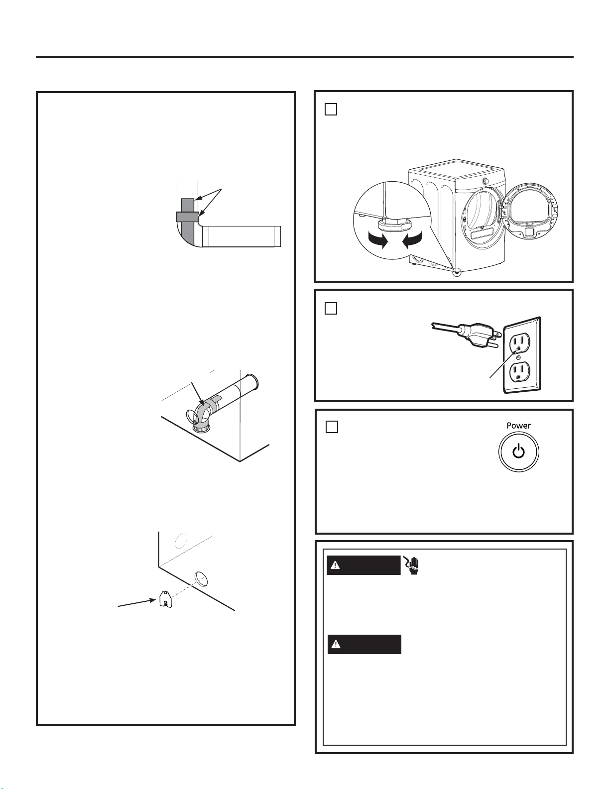
FINAL SETUP
LEVEL THE DRYER
Stand the dryer upright near the final location and
adjust the four leveling legs at the corners to ensure
that the dryer is level from side to side and front to
rear.
Lower
Raise
PLUG DRYER IN
1
2
DRYER START-UP
Press the Power button.
NOTE: If the dryer has been
exposed to temperatures
below freezing for an extended
period of time, allow it to warm up before pressing Power.
Otherwise, the display will not come on.
The dryer is now ready for use.
3
Ensure proper
ground exists
before use.
Connect standard metal elbows and ducts to complete
the exhaust system. Cover back opening with the plate
(kit WE49X22606) which can be purchased from
GEApplianceparts.com or a local service provider.
Place dryer in final location.
Plate
(Kit WE49X22606)
NEVER LEAVE THE BACK OPENING WITHOUT
THE PLATE.
(appearance will vary)
Disconnect power supply before servicing.
Replace all parts and panels before operating.
Failure to do so can result in death or electrical
shock.
WARNING
- Shock Hazard
Certain internal parts are intentionally not grounded
and may present a risk of electric shock only during
servicing.
Service personnel – DO NOT contact the following
parts while the appliance is energized: Power
button, Start/Pause button, electronic board, outlet
thermostat, outlet thermistor or water valve.
- Electrical Shock Hazard
WARNING
16
Loading ...
Loading ...
Loading ...