
All-New Wrangler
OWNER’S MANUAL
2019
Third Edition
Printed in the U.S.A.
19JL-126-AC
2019 All-New Wrangler
©2019 FCA US LLC. All Rights Reserved. Jeep is a registered trademark of FCA US LLC. App Store
is a registered trademark of Apple Inc. Google Play Store is a registered trademark of Google.

INSTALLATION OF RADIO TRANSMITTING
EQUIPMENT
Special design considerations are incorporated into this
vehicle’s electronic system to provide immunity to radio
frequency signals. Mobile two-way radios and telephone
equipment must be installed properly by trained person-
nel. The following must be observed during installation.
The positive power connection should be made directly
to the battery and fused as close to the battery as possible.
The negative power connection should be made to body
sheet metal adjacent to the negative battery connection.
This connection should not be fused.
Antennas for two-way radios should be mounted on the
roof or the rear area of the vehicle. Care should be used
in mounting antennas with magnet bases. Magnets may
affect the accuracy or operation of the compass on
vehicles so equipped.
The antenna cable should be as short as practical and
routed away from the vehicle wiring when possible. Use
only fully shielded coaxial cable.
Carefully match the antenna and cable to the radio to
ensure a low Standing Wave Ratio (SWR).
Mobile radio equipment with output power greater than
normal may require special precautions.
All installations should be checked for possible interfer-
ence between the communications equipment and the
vehicle’s electronic systems.
WARNING:
Operating, servicing and maintaining a
passenger vehicle or off-road highway
motor vehicle can expose you to chemicals
including engine exhaust, carbon monoxide,
phthalates, and lead, which are known to
the State of California to cause cancer and
birth defects or other reproductive harm.
To minimize exposure, avoid breathing
exhaust, do not idle the engine except as
necessary, service your vehicle in a
well-ventilated area and wear gloves or
wash your hands frequently when servicing
your vehicle. For more information go to
www.P65Warnings.ca.gov/passenger-vehicle.
VEHICLES SOLD IN CANADA
With respect to any Vehicles Sold in Canada, the name
FCA US LLC shall be deemed to be deleted and the name
FCA Canada Inc. used in substitution therefore.
DRIVING AND ALCOHOL
Drunken driving is one of the most frequent causes of
accidents.
Your driving ability can be seriously impaired with blood
alcohol levels far below the legal minimum. If you are
drinking, don’t drive. Ride with a designated non-
drinking driver, call a cab, a friend, or use public trans-
portation.
WARNING!
Driving after drinking can lead to an accident.
Your perceptions are less sharp, your reflexes are
slower, and your judgment is impaired when you
have been drinking. Never drink and then drive.
This manual illustrates and describes the operation of
features and equipment that are either standard or op-
tional on this vehicle. This manual may also include a
description of features and equipment that are no longer
available or were not ordered on this vehicle. Please
disregard any features and equipment described in this
manual that are not on this vehicle.
FCA US LLC reserves the right to make changes in design
and specifications, and/or make additions to or improve-
ments to its products without imposing any obligation
upon itself to install them on products previously manu-
factured.
Copyright © 2018 FCA US LLC
Copyright © 2019 FCA US LLC

TABLE OF CONTENTS
1
2
3
4
5
6
7
8
9
10
11
1 INTRODUCTION .................................................................................................................................................................................12
2 GETTING TO KNOW YOUR VEHICLE ........
.................................................................................................................................16
3 GETTING TO KNOW YOUR INSTRUMENT PANEL ........
......................................................................................................189
4 SAFETY .................................................................................................................................................................................................219
5 STARTING
AND OPERATING ........
..............................................................................................................................................308
6 IN CASE OF EMERGENCY ........
......................................................................................................................................................412
7 SERVICING AND MAINTENANCE ........
.....................................................................................................................................452
8 TECHNICAL SPECIFICATIONS ........
............................................................................................................................................528
9 MULTIMEDIA ........
............................................................................................................................................................................540
10 CUSTOMER ASSISTANCE ........
.....................................................................................................................................................611
11 INDEX ....................................................................................................................................................................................................616

2
INTRODUCTION
INTRODUCTION ..............................................................12
ROLLOVER WARNING .......
............................................13
HOW TO USE THIS MANUAL .......
................................14
Essential Information....................................................14
Symbols...........................................................................14
WARNINGS AND CAUTIONS .......
................................15
VEHICLE MODIFICATIONS/ALTERATIONS .......
....15
GETTING TO KNOW YOUR VEHICLE
VEHICLE USER GUIDE — IF EQUIPPED......................16
KEYS .....................................................................................18
Key Fob ...........................................................................18
IGNITION SWITCH .......
..................................................22
Keyless Enter-N-Go — Ignition...................................22
Vehicle On Message .....................................................24
REMOTE STARTING SYSTEM — IF EQUIPPED .......
.25
How To Use Remote Start............................................26
Remote Start Cancel Message — If Equipped...........27
To Enter Remote Start Mode........................................27
To Exit Remote Start Mode Without Driving The
Vehicle ............................................................................27
To Exit Remote Start Mode And Drive The Vehicle ... 28
Remote Start Comfort Systems — If Equipped ........28
General Information .....................................................28
SENTRY KEY .......
................................................................29
Replacement Keys ........................................................29
General Information .....................................................30
VEHICLE SECURITY ALARM — IF EQUIPPED .......
..30
To Arm The System ......................................................30
To Disarm The System .................................................31
Rearming Of The System..............................................31
DOORS .................................................................................32
Manual Door Locks .......................................................32
Power Door Locks — If Equipped .............................33
Keyless Enter-N-Go — Passive Entry
(If Equipped) .......
..........................................................34
Child-Protection Door Lock System — Rear Doors.... 39
Automatic Door Locks — If Equipped .....................40
Front Door Removal ....................................................40
Rear Door Removal (Four-Door Models) ..................44

3
SEATS ...............................................................................47
Manual Front Seats........................................................47
Heated Seats — If Equipped........................................49
Front Passenger Easy Entry Seat — Two Door
Models.............................................................................50
60/40 Split Folding Rear Seat — Four Door Models...51
Fold And Tumble Rear Seat — Two Door Models...52
Rear Seat Armrest — If Equipped...............................54
HEAD RESTRAINTS .......
.................................................55
Front Head Restraints...................................................55
Rear Head Restraints — Two Door Models ..............57
Rear Head Restraints — Four Door Models..............58
STEERING WHEEL .......
.....................................................60
Tilt/Telescoping Steering Column ...........................60
Heated Steering Wheel — If Equipped ....................61
MIRRORS .......
.....................................................................62
Inside Day/Night Mirror — If Equipped..................62
Automatic Dimming Mirror — If Equipped ............62
Outside Mirrors ............................................................63
Power Mirrors — If Equipped ...................................64
Heated Mirrors — If Equipped .................................64
Vanity Mirrors ..............................................................64
EXTERIOR LIGHTS .......
...................................................65
Headlight Switch ...........................................................65
Daytime Running Lights — If Equipped ..................65
High/Low Beam Switch .............................................66
Flash-To-Pass ................................................................66
Automatic Headlights — If Equipped .......................66
Front Fog Lights — If Equipped..................................67
Turn Signals....................................................................67
Lane Change Assist — If Equipped............................67
Lights-On Reminder......................................................67
INTERIOR LIGHTS .......
.....................................................68
Courtesy Lights..............................................................68
Dimmer Controls ...........................................................69
WINDSHIELD WIPERS AND WASHERS .......
.............69
Windshield Wiper Operation ......................................70
CLIMATE CONTROLS .......
...............................................73
Manual Climate Control Overview ............................73
Automatic Climate Controls Overview......................77
Climate Control Functions ...........................................83
Automatic Temperature Control (ATC) — If
Equipped .......
................................................................84
Operating Tips ..............................................................84
POWER WINDOWS — IF EQUIPPED .......
....................86
Auto-Down Feature ......................................................87
Wind Buffeting ..............................................................88

4
DUAL TOP FOUR DOOR MODELS —
IF EQUIPPED .......
.............................................................88
Removing The Soft Top — Four Door Models .........89
Installing The Soft Top — Four Door Models...........92
FREEDOM TOP THREE-PIECE MODULAR HARD
TOP —
IF EQUIPPED .......
.................................................95
Front Panel(s) Removal ................................................96
Freedom Top Storage Bag ............................................97
Front Panel(s) Installation ............................................99
Rear Hard Top Removal...............................................99
Rear Hard Top Installation ........................................104
DOOR FRAME .......
..........................................................104
Door Frame Removal..................................................105
Door Frame Installation Four Door Models — If
Equipped.......................................................................106
Door Frame Installation Two Door Models — If
Equipped.......................................................................109
SOFT TOP TWO DOOR MODELS —
I
F EQUI
PPED .......
.............................................................110
Lowering The Soft Top ...............................................112
Soft Top Window Storage Bag ..................................123
Raising The Soft Top ...................................................127
SOFT TOP FOUR DOOR MODELS —
IF EQUI
PPED .......
.............................................................136
Lowering The Soft Top ...............................................138
Raising The Soft Top ...................................................149
POWER SLIDING TOP — IF EQUIPPED .......
..........157
Opening The Power Top.............................................159
Closing The Power Top ..............................................159
Wind Buffeting ............................................................159
Pinch Protect Feature ..................................................160
Power Top Maintenance.............................................160
Ignition Off Operation ................................................160
Relearn Procedure .......................................................161
Rear Quarter Window Removal................................161
FOLDING WINDSHIELD .......
........................................165
Lowering The Windshield..........................................166
Raising The Windshield..............................................168
HOOD .............................................................................169
Opening The Hood......................................................169
Closing The Hood........................................................169
REAR SWING GATE .......
...............................................170
Cargo Area Features ...............................................171
GARAGE DOOR OPENER — IF EQUIPPED .......
.......171
Before You Begin Programming HomeLink............172
Canadian/Gate Operator Programming..................175
Using HomeLink..........................................................176
Security..........................................................................177
Troubleshooting Tips ..................................................177
General Information....................................................178

5
INTERNAL EQUIPMENT ...............................................178
Storage...........................................................................178
Cupholders...................................................................180
Electrical Power Outlets .........................................182
Power Inverter — If Equipped .................................184
Auxiliary Switches — If Equipped ..........................185
ROOF LUGGAGE RACK — IF EQUIPPED .......
.........187
GETTING TO KNOW YOUR INSTRUMENT
PANEL
INSTRUMENT CLUSTER ...............................................189
Instrument Cluster Descriptions...............................190
INSTRUMENT CLUSTER DISPLAY .......
......................193
Instrument Cluster Display Location And
Controls.........................................................................193
Oil Change Reset — If Equipped ..............................196
Instrument Cluster Display Menu Items ................196
Battery Saver On/Battery Saver Mode Message —
Electrical Load Reduction Actions —
If Equipped .
......
.........................................................201
WARNING LIGHTS AND MESSAGES.......
..................203
Red Warning Lights ....................................................203
Yellow Warning Lights...............................................208
Yellow Indicator Lights ..............................................212
Green Indicator Lights ................................................213
White Indicator Lights ................................................214
Blue Indicator Lights...................................................215
Gray Indicator Lights..................................................216
ONBOARD DIAGNOSTIC SYSTEM — OBD II .......
.216
Onboard Diagnostic System (OBD II)
Cybersecurity .......
........................................................217
EMISSIONS INSPECTION AND MAINTENANCE
PROGRAMS .
......
..............................................................217
SAFETY
SAFETY FEATURES .........................................................219
Anti-Lock Brake System (ABS) .................................219
Electronic Brake Control System ..............................220
AUXILIARY DRIVING SYSTEMS.......
...........................231
Blind Spot Monitoring (BSM) — If Equipped ........231
Forward Collision Warning (FCW) With Mitigation —
If Equipped.......
............................................................239
Tire Pressure Monitor System (TPMS) ..................243

6
OCCUPANT RESTRAINT SYSTEMS ...........................250
Occupant Restraint Systems Features .....................250
Important Safety Precautions ....................................250
Seat Belt Systems ........................................................251
Supplemental Restraint Systems (SRS) ....................261
Child Restraints .........................................................282
Transporting Pets .....................................................304
SAFETY TIPS .......
...........................................................304
Transporting Passengers ............................................304
Exhaust Gas .............................................................304
Safety Checks You Should Make Inside The
Vehicle ..........................................................................305
Periodic Safety Checks You Should Make Outside The
Vehicle...........................................................................307
STARTING AND OPERATING
STARTING THE ENGINE ..............................................308
Manual Transmission — If Equipped .....................308
Automatic Transmission — If Equipped ................309
Normal Starting .......................................................309
Extreme Cold Weather (Below –22°F Or −30°C) ...312
If Engine Fails To Start ..............................................313
After Starting................................................................313
ENGINE BLOCK HEATER — IF EQUIPPED .......
.......314
ENGINE BREAK-IN RECOMMENDATIONS .......
......314
PARKING BRAKE .......
...................................................315
MANUAL TRANSMISSION — IF EQUIPPED .......
...317
Shifting ..........................................................................318
Downshifting................................................................319
AUTOMATIC TRANSMISSION — IF EQUIPPED ....321
Ignition Park Interlock ................................................322
Brake/Transmission Shift Interlock System ...........322
Eight–Speed Automatic Transmission .....................322
FOUR–WHEEL DRIVE OPERATION .......
....................330
Four-Position Transfer Case.......................................330
Five-Position Transfer Case .......................................333
Trac-Lok Rear Axle — If Equipped ..........................337
Axle Lock (Tru-Lok) — Rubicon Models ...............338
Electronic Sway Bar Disconnect — If Equipped ....339
ELECTRO-HYDRAULIC POWER STEERING.......
......340
STOP/START SYSTEM — AUTOMATIC
TRANSMISSION (IF EQUIPPED) .
......
...........................341
Automatic Mode ..........................................................342
Possible Reasons The Engine Does Not Autostop..343
To Start The Engine While In Autostop Mode........344
To Manually Turn Off The Stop/Start System........345
To Manually Turn On The Stop/Start System........345
System Malfunction.....................................................345

7
STOP/START SYSTEM — MANUAL TRANSMISSION
(IF EQUIPPED).......
...........................................................346
Automatic Mode..........................................................347
Possible Reasons The Engine Does Not Autostop..348
To Start The Engine While In Autostop Mode........348
To Manually Turn Off The Start/Stop System........349
To Manually Turn On The Stop/Start System........350
System Malfunction ....................................................350
SPEED CONTROL — IF EQUIPPED .......
....................350
To Activate ...................................................................351
To Set A Desired Speed ..............................................351
To Vary The Speed Setting.........................................352
To Accelerate For Passing .........................................353
To Resume Speed .......................................................353
To Deactivate ...............................................................353
ADAPTIVE CRUISE CONTROL (ACC) —
IF EQUI
PPED .......
.............................................................354
Activating Adaptive Cruise Control (ACC)............356
To Activate/Deactivate ..............................................356
To Set A Desired ACC Speed.....................................357
To Cancel ......................................................................358
To Turn Off...................................................................358
To Resume ....................................................................358
To Vary The Speed Setting ........................................359
Setting The Following Distance In ACC ..................361
Overtake Aid ................................................................364
ACC Operation At A Stop (Automatic Transmission
Only)..............................................................................364
Adaptive Cruise Control (ACC) Menu.....................364
Display Warnings And Maintenance .......................365
Precautions While Driving With ACC .....................368
General Information....................................................372
Normal (Fixed Speed) Cruise Control Mode...........372
PARKSENSE REAR PARK ASSIST —
IF EQUI
PPED .......
............................................................375
ParkSense Sensors........................................................375
ParkSense Warning Display.......................................376
ParkSense Display .......................................................376
Enabling And Disabling ParkSense ..........................380
Service The ParkSense Rear Park Assist System.....380
Cleaning The ParkSense System................................381
ParkSense System Usage Precautions.......................381
PARKVIEW REAR BACK UP CAMERA .......
.............382
REFUELING THE VEHICLE .......
...................................385
Fuel Filler Cap ............................................................385
Loose Fuel Filler Cap Message .................................386

8
VEHICLE LOADING ....................................................387
Certification Label .......................................................387
TRAILER TOWING .......
..................................................389
Common Towing Definitions....................................389
Trailer Hitch Classification ........................................391
Trailer Towing Weights (Maximum Trailer Weight
Ratings) ........................................................................392
Trailer And Tongue Weight .....................................393
Towing Tips..................................................................395
RECREATIONAL TOWING (BEHIND MOTORHOME,
ETC.) .
.................................................................................397
Towing This Vehicle Behind Another Vehicle........397
Recreational Towing — Four-Wheel Drive
Models...........................................................................398
DRIVIN
G TIPS.......
............................................................400
On-Road Driving Tips ................................................400
Off-Road Driving Tips................................................401
IN CASE OF EMERGENCY
HAZARD WARNING FLASHERS ..............................412
ASSIST AND SOS SYSTEM — IF EQUIPPED.......
.......412
BULB REPLACEMENT .......
...........................................417
Replacement Bulbs ..................................................417
Bulb Replacement ......................................................419
FUSES .................................................................................423
General Information....................................................423
Power Distribution Center (PDC) .............................424
JACKING AND TIRE CHANGING .......
........................432
Jack Location ...............................................................433
Spare Tire Removal ....................................................435
Preparations For Jacking ............................................436
Jacking Instructions ...................................................436
Road Tire Installation..................................................440
MANUAL PARK RELEASE .......
.....................................440
JUMP STARTING .......
......................................................442
Preparations For Jump Start.......................................443
Jump Starting Procedure ............................................445
IF YOUR ENGINE OVERHEATS .......
...........................447
FREEING A STUCK VEHICLE .......
...............................447
TOWING A DISABLED VEHICLE .......
........................449
Four–Wheel Drive Models .........................................450
Emergency Tow Hooks — If Equipped ...................450
ENHANCED ACCIDENT RESPONSE SYSTEM
(EARS)
................................................................................451
EVENT
DATA RECORDER (EDR).......
..........................451

9
SERVICING AND MAINTENANCE
SCHEDULED SERVICING .............................................452
Maintenance Plan ........................................................453
Heavy Duty Use Of The Vehicle ...............................457
ENGINE COMPARTMENT .......
...................................458
2.0L Engine ..................................................................458
3.6L Engine ..................................................................459
Checking Oil Level .....................................................460
Adding Washer Fluid ...............................................460
Maintenance-Free Battery .........................................461
DEALER SERVICE .......
....................................................462
Engine Oil ....................................................................462
Engine Oil Filter .........................................................464
Engine Air Cleaner Filter .........................................465
Accessory Drive Belt Inspection................................467
Air Conditioner Maintenance ..................................468
Body Lubrication .......................................................472
Windshield Wiper Blades .........................................472
Exhaust System ...........................................................476
Cooling System ............................................................478
Brake System ...............................................................484
Front/Rear Axle Fluid ...............................................485
Transfer Case ...............................................................485
Manual Transmission ................................................486
Automatic Transmission ...........................................487
RAISING THE VEHICLE .......
........................................488
TIRES...................................................................................488
Tire Safety Information ............................................488
Tires — General Information ....................................498
Tire Types .....................................................................504
Spare Tires — If Equipped .......................................505
Wheel And Wheel Trim Care ..................................507
Tire Chains (Traction Devices) .................................509
Tire Rotation Recommendations ..............................510
DEPARTMENT OF TRANSPORTATION UNIFORM
TIRE QUALITY GRADES .
......
........................................511
Treadwear.....................................................................511
Traction Grades............................................................511
Temperature Grades ...................................................511
STORING THE VEHICLE .......
......................................512
BODYWORK.......
...............................................................514
Protection From Atmospheric Agents ....................514
Body And Underbody Maintenance.........................514
Preserving The Bodywork..........................................515
INTERIORS .......
................................................................518
Carpet Removal ...........................................................518
Seats And Fabric Parts ................................................525
Plastic And Coated Parts ............................................526
Leather Parts.................................................................526
Glass Surfaces ..............................................................527

10
TECHNICAL SPECIFICATIONS
VEHICLE IDENTIFICATION NUMBER .....................528
BRAKE SYSTEM.......
.........................................................529
WHEEL AND TIRE TORQUE SPECIFICATIONS .....52
9
Torque Specifications..................................................529
FUEL REQUIREMENTS .....
...........................................531
2.0L Engine ...................................................................531
3.6L Engine ...................................................................531
Reformulated Gasoline ..........................................532
Materials Added To Fuel ..........................................532
Gasoline/Oxygenate Blends ....................................532
Do Not Use E-85 In Non-Flex Fuel Vehicles............533
CNG And LP Fuel System Modifications................533
MMT In Gasoline.........................................................533
Fuel System Cautions..................................................533
Carbon Monoxide Warnings ...................................534
FLUID CAPACITIES .......
.............................................535
FLUIDS AND LUBRICANTS.......
...................................536
Engine ........................................................................536
Chassis ........................................................................539
MULTIMEDIA
UCONNECT SYSTEMS ...................................................540
DRAG & DROP MENU BAR .......
..................................540
CYBERSECURITY .......
.....................................................541
UCONNECT SETTINGS .......
...........................................543
Customer Programmable Features —
Uconnect 3 Settings .......
.............................................543
Customer Programmable Features — Uconnect 4
Settings .........................................................................554
Customer Programmable Features — Uconnect 4C/
4C NAV Settings.......
...................................................566
STEERING WHEEL AUDIO CONTROLS .......
..........582
Radio Operation...........................................................582
Media Mode..................................................................582
AUX/USB/MP3 CONTROL — IF EQUIPPED .......
....583
RADIO OPERATION AND MOBILE PHONES .......
..587
Regulatory And Safety Information .........................587

11
UCONNECT VOICE RECOGNITION QUICK TIPS ....588
Introducing Uconnect .................................................588
Get Started ....................................................................590
Basic Voice Commands ..............................................591
Radio .............................................................................591
Media.............................................................................593
Phone.............................................................................595
Voice Text Reply..........................................................597
Climate ..........................................................................598
Navigation (4C NAV) — If Equipped......................600
SiriusXM Guardian (4C/4C NAV) — If Equipped ...601
Register (4C/4C NAV) ...............................................602
Vehicle Health Report/Alert (4C/4C NAV) ..........602
Mobile App (4C/4C NAV).........................................602
SiriusXM Travel Link (4C NAV)...............................603
Siri Eyes Free — If Equipped ....................................604
Using Do Not Disturb ................................................605
Android Auto — If Equipped ...................................606
Apple CarPlay — If Equipped ..................................607
General Information....................................................609
Additional Information ..............................................609
CD/DVD DISC MAINTENANCE .......
.........................610
CUSTOMER ASSISTANCE
SUGGESTIONS FOR OBTAINING SERVICE FOR YOUR
VEHICLE .......
....................................................................611
Prepare For The Appointment...................................611
Prepare A List...............................................................611
Be Reasonable With Requests ....................................611
IF YOU NEED ASSISTANCE .......
..................................611
FCA US LLC Customer Center..................................612
FCA Canada Inc. Customer Center...........................612
In Mexico Contact........................................................612
Puerto Rico And U.S. Virgin Islands ........................612
Customer Assistance For The Hearing Or Speech
Impaired (TDD/TTY) .......
..........................................613
Service Contract ..........................................................613
WARRANTY INFORMATION.......
................................614
MOPAR PARTS.......
..........................................................614
REPORTING SAFETY DEFECTS .......
............................614
In The 50 United States And Washington, D.C.......614
In Canada......................................................................615
PUBLICATION ORDER FORMS .......
............................615

12
INTRODUCTION
INTRODUCTION
Dear Customer, congratulations on selecting your new
vehicle. Be assured that it represents precision workman-
ship, distinctive styling, and high quality.
This is a specialized utility vehicle. It can go places and
p
erform
tasks that are not intended for conventional
passenger vehicles. It handles and maneuvers differently
from many passenger vehicles both on-road and off-road, so
take time to become familiar with your vehicle. If equipped,
the two-wheel drive version of this vehicle was designed for
on-road use only. It is not intended for off-road driving or
use in other severe conditions suited for a four-wheel drive
vehicle. Before you start to drive this vehicle, read the
Owner’s Manual. Be sure you are familiar with all vehicle
controls, particularly those used for braking, steering, trans
-
mission, and transfer case shifting. Learn how your vehicle
handles
on different road surfaces. Your driving skills will
improve with experience. When driving off-road, or
working the vehicle, don’t overload the vehicle or expect the
vehicle to overcome the natural laws of physics. Always
observe federal, state, provincial and local laws wherever
you drive. As with other vehicles of this type, failure to
operate this vehicle correctly may result in loss of control or
a collision. Refer to the “Driving Tips” in “Starting and Oper
-
ating” for further information.
This Owner’s Manual has been prepared with the assistance
of servi
ce and engineering specialists to acquaint you with
the operation and maintenance of your vehicle. It is supple
-
mented by Warranty Information, and customer oriented
document
s. In the attached Warranty Booklet you will find a
description of the services that FCA offers to its customers,
the Warranty Certificate and the details of the terms and
conditions for maintaining its validity. Please take the time
to read all of these publications carefully before driving your
vehicle for the first time. Following the instructions, recom
-
mendations, tips, and important warnings in this manual
will help
assure safe and enjoyable operation of your vehicle.
This Owner’s Manual describes all versions of this vehicle.
Options
and equipment dedicated to specific markets or
versions are not expressly indicated in the text. Therefore,
you should only consider the information which is related to
the trim level, engine, and version that you have purchased.
Any content introduced throughout the Owner’s Informa
-
tion, that may or may not be applicable to your vehicle, will

INTRODUCTION 13
be identified with the wording “If Equipped”. All data
contained in this publication are intended to help you use
your vehicle in the best possible way. FCA aims at a constant
improvement of the vehicles produced. For this reason, it
reserves the right to make changes to the model described for
technical and/or commercial reasons. For further informa
-
tion, contact an authorized dealer.
If applicable, refer to the Owner’s Manual Supplement for
r
elated
information.
NOTE:
After reviewing the Owner’s Information, it should be stored
in the vehicle for convenient referencing, and remain with
the vehicle when sold.
When it comes to service, remember that your authorized
dealer kn
ows your vehicle best, has factory-trained techni-
cians and genuine MOPAR® parts, and cares about your
s
atisfac
tion.
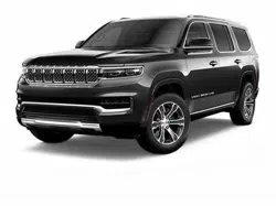
ROLLOVER WARNING
Utility vehicles have a significantly higher rollover rate than
other types of vehicles. This vehicle has a higher ground
clearance and a higher center of gravity than many
passenger vehicles. It is capable of performing better in a
wide variety of off-road applications. Driven in an unsafe
manner, all vehicles can go out of control. Because of the
higher center of gravity, if this vehicle is out of control it may
roll over while some other vehicles may not.
Do not attempt sharp turns, abrupt maneuvers, or other unsafe
driving
actions that can cause loss of vehicle control. Failure to
operate this vehicle safely may result in a collision, rollover of
the vehicle, and severe or fatal injury. Drive carefully.
1
14 INTRODUCTION
Rollover Warning Label
Failure to use the driver and passenger seat belts provided is a
major ca
use of severe or fatal injury. In fact, the U.S. govern-
ment notes that the universal use of existing seat belts could
c
ut the
highway death toll by 10,000 or more each year and
could reduce disabling injuries by two million annually. In a
rollover crash, an unbelted person is significantly more likely
to die than a person wearing a seat belt. Always buckle up.
HOW TO USE THIS MANUAL
Essential Information
Consult the Table of Contents to determine which section
contains the information you desire.
Since the specification of your vehicle depends on the items
of equi
pment ordered, certain descriptions and illustrations
may differ from your vehicle's equipment.
The detailed index at the back of this Owner's Manual
contain
s a complete listing of all subjects.
Symbols
Some vehicle components have colored labels whose
symbols indicate precautions to be observed when using this
component. Refer to “Warning Lights and Messages” in
“Getting To Know Your Instrument Panel” for further infor
-
mation on the symbols used in your vehicle.

INTRODUCTION 15
WARNINGS AND CAUTIONS
This Owner’s Manual contains WARNINGS against oper-
ating procedures that could result in a collision, bodily injury
and/or d
eath. It also contains CAUTIONS against proce-
dures that could result in damage to your vehicle. If you do
n
ot rea
d this entire Owner’s Manual, you may miss
important information. Observe all Warnings and Cautions.
VEHICLE MODIFICATIONS/ALTERATIONS
WARNING!
Any modifications or alterations to this vehicle could
seriousl
y affect its roadworthiness and safety and may
lead to a collision resulting in serious injury or death.
1
16
GETTING TO KNOW YOUR VEHICLE
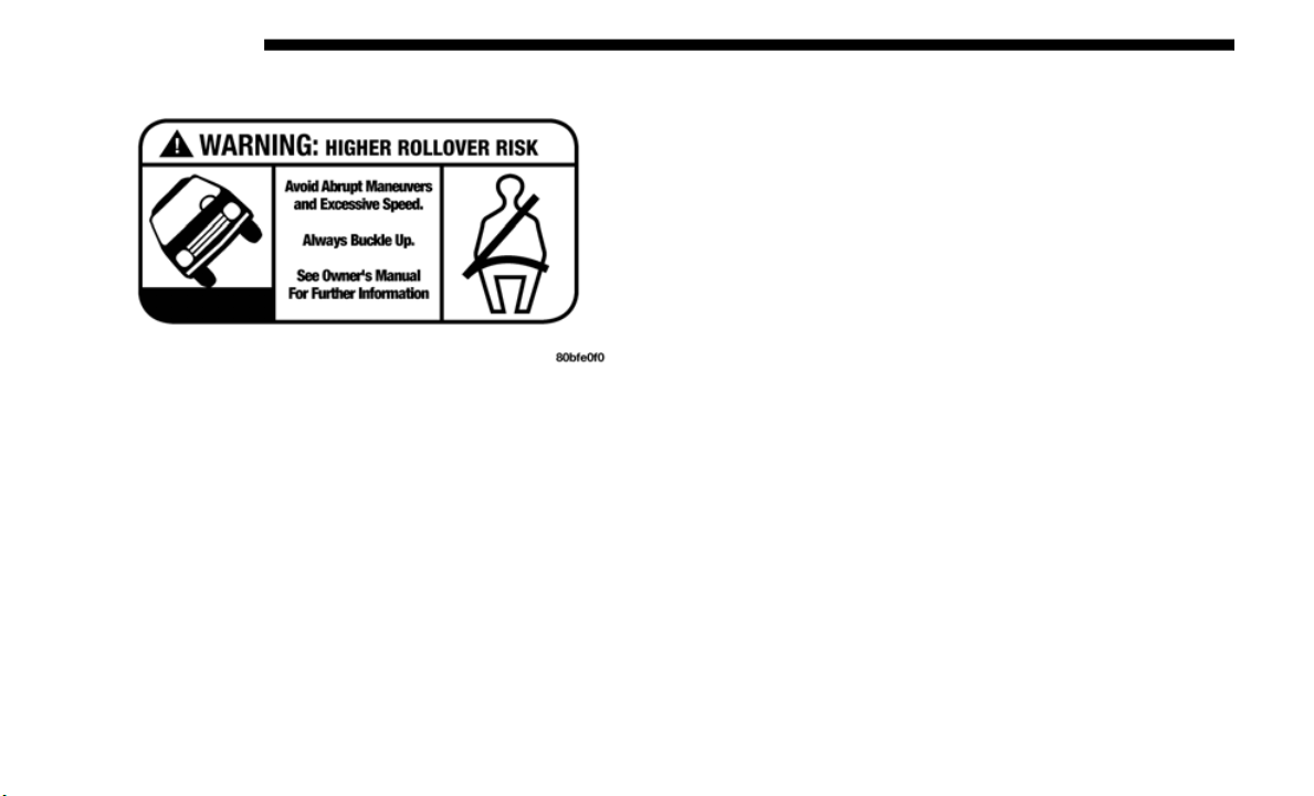
VEHICLE USER GUIDE — IF EQUIPPED
Access your Owner’s Information right through your Ucon-
nect 4C or 4C NAV touchscreen system — If Equipped.
To access the Vehicle User Guide on your Uconnect Touch-
screen: Press the Uconnect A
pps butt
on. From there, press
the Vehicle User Guide icon on your touchscreen. No Ucon-
nect registration is required.
Uconnect 4C NAV With 8.4–inch Display Vehicle User
G
uide Tou
chscreen Icon

GETTING TO KNOW YOUR VEHICLE 17
NOTE:
Vehicle User Guide features are not available while the
vehicle
is moving. If you try to access while the vehicle is in
motion, the system will display: Feature not available while
the vehicle is in motion.
Pre-Installed Features
Once you launch your Vehicle User Guide, you will be able
t
o expl
ore your warranty information and radio manual
when and where you need them. Your Uconnect system
displays the Vehicle User Guide on your touchscreen radio
to assist in better understanding your vehicle. There’s no app
to download, no phone to connect and no external device
needed for playback. Plus, it’s updated throughout the year,
in real-time, so it never goes out of date.
Features/Benefits
• Pre-installed on your Uconnect touchscreen radio
• Enhanc
ed search and browsing capability
• Robust
NAV application — If Equipped
• Add se
lected topics to a fast-access Favorites category
• Icon a
nd symbol glossary
• Warran
ty information
• Crucia
l driver information and assistance:
Tip:
Wh
en viewing a topic, tap the star icon to add it to your
Favorite
s, for easy access in the future.
Your User Guide —
Updated
in real-time
Available when and where
you need it
Touchscreen convenience Customizable interface
Maintenance schedules and
informa
tion
Multilingual
Comprehensive icon &
symbol gl
ossary
Operating Instructions Maintenance Schedules
Warranty Information Emergency Procedures
Fluid Level Standards 911 Contact and More
2
18 GETTING TO KNOW YOUR VEHICLE
KEYS
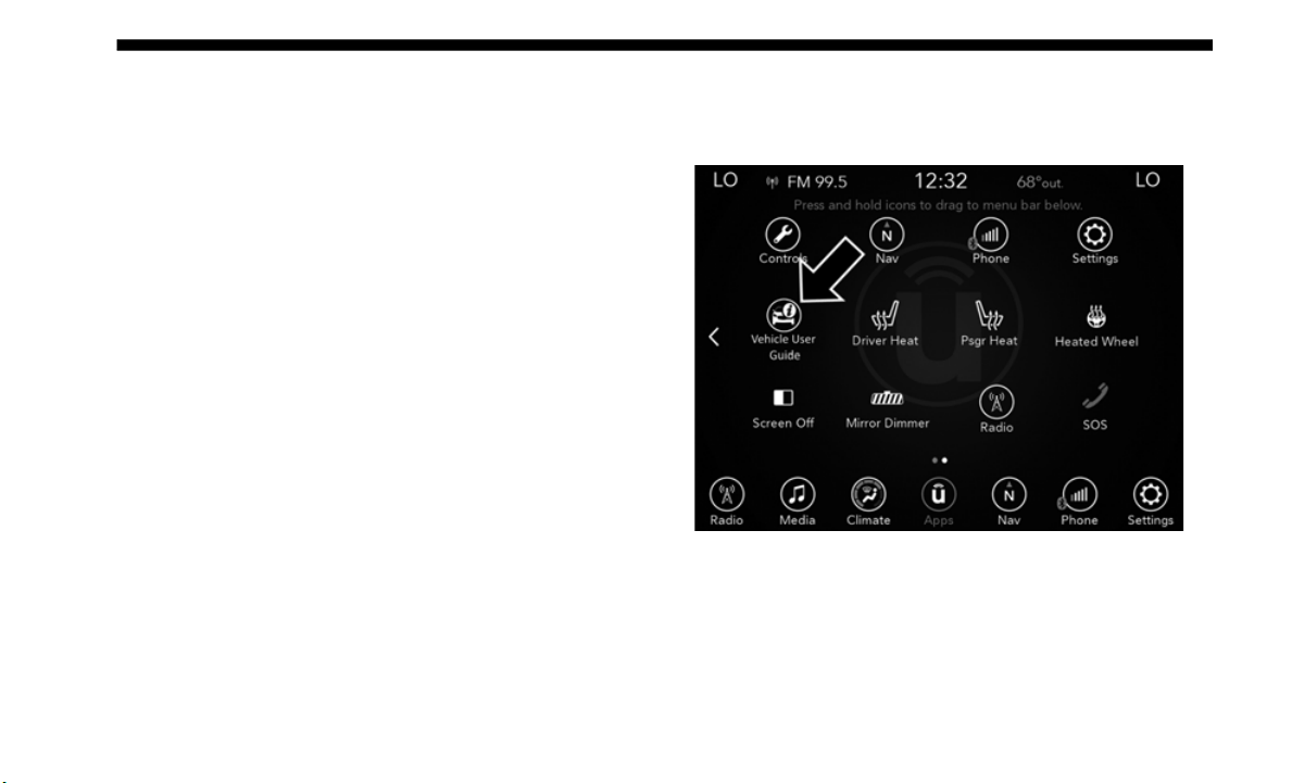
Key Fob
Key Fob
Your vehicle uses a keyless ignition system. The ignition
s
ys
tem co
nsists of a key fob with Keyless Go and a START/
STOP push button ignition system. The Remote Keyless
Entry system consists of a key fob with a mechanical key and
Keyless Enter-N-Go feature if equipped.
NOTE:
The key fob may not be detected by the vehicle if it is located
next to
a mobile phone, laptop or other electronic device;
these devices may block the key fob’s wireless signal.
1 — Flip Key Release Button
2 — Unlock Button
3 — Lock Button
4 — Remote Start Button
5 — Panic Button
WARNING!
Push the Mechanical Key Release Button only with the
key fob fa
cing away from your body, especially your
eyes and objects that may be damaged, such as clothing.
CAUTION!
The electrical components inside of the key fob may be
damaged i
f the key fob is subjected to strong electrical
shocks. In order to ensure complete efficiency of the
electronic devices inside of the key fob, avoid exposing
the key fob to direct sunlight.
GETTING TO KNOW YOUR VEHICLE 19
The key fob allows you to lock or unlock the doors and swing
gate from distances up to approximately 66 ft (20 m) by
pressing
the appropriate button on the fob. The key fob does
not need to be pointed at the vehicle to activate the system.
NOTE:
With the ignition in ON/RUN position and with the vehicle
doors op
en, the lock button will be disabled, and only the
unlock button will be enabled. All RKE commands will be
disabled once the vehicle begins moving at 5
mph (8 km/h)
or above
.
Backup Mode Starting
In case the ignition switch does not change with the push of
a button
, the key fob may have a low or fully depleted
battery. A low key fob battery can be verified by referring to
the instrument cluster, which will display directions to
follow.
NOTE:
A low key fob battery condition may be indicated by a
message i
n the instrument cluster display, or by the LED
light on the key fob. If the LED key fob light no longer illu
-
minates from key fob button pushes, then the key fob battery
requires
replacement.
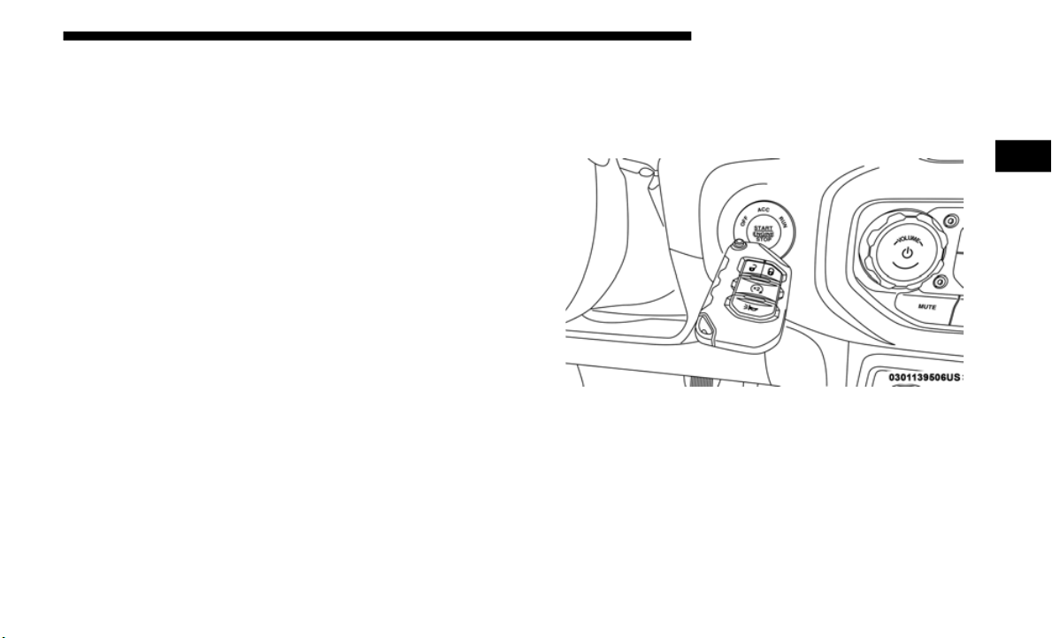
In this situation, a back up method can be used to operate the
ignition
switch. Put the nose side of the key fob against the
ENGINE START/STOP button, and push to operate the igni
-
tion switch.
Backup Starting Method
To Unlock The Doors And Swing Gate
Push and release the key fob unlock button once to unlock
the driv
er's door only, or twice to unlock all the doors and
swing gate. When the key fob unlock button is pushed, the
Illuminated Entry will initiate, and the turn signal lights will
flash twice.
2
20 GETTING TO KNOW YOUR VEHICLE
To Lock The Doors And Swing Gate
Push and release the lock button on the key fob to lock all
doors. T
he turn signals will flash, and the horn will chirp
once to acknowledge the lock signal.
Key Fob Battery Replacement
NOTE:
When a key fob battery is low, a warning will be indicated on
the vehi
cle’s instrument cluster, and the fob LED will no
longer illuminate with a button press.
The recommended replacement battery is CR2450.
NOTE:
Perchlorate Material – special handling may apply. See
www.dtsc.ca.gov/hazardouswaste/perchlorate .
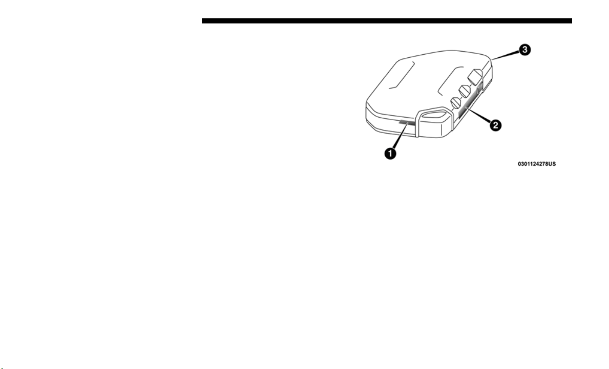
1. R
emove the back cover of the fob by inserting a flat-blade
screw dr
iver into the slot on the bottom of the fob. Pry
until the cover unsnaps being careful not to damage the
seal. Proceed counter-clockwise to pry the remaining
snaps until the battery cover can be removed.
1-3 – Back Cover Pry Points
2. Remove the depleted battery by inserting a small
flat-bl
ade screwdriver into the battery removal slot and
sliding the battery forward and up being careful not to
damage the electronic board underneath.
GETTING TO KNOW YOUR VEHICLE 21
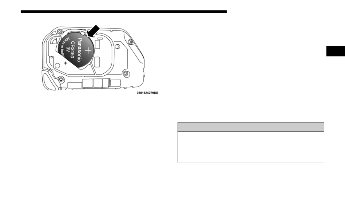
Battery Replacement
3. Install the new battery into the key fob, making sure the
positiv
e (+) side is facing up. Slide the battery until it is
seated securely below the tabs.
4. Reassemble the back cover making sure it is properly
aligned
before snapping it back in place.
Programming Additional Key Fobs
Programming the key fob may be performed by an autho-
rized dealer.
NOTE:
Once a key fob is programmed to a vehicle, it cannot be
r
epurpos
ed and reprogrammed to another vehicle.
Request For Additional Key Fobs
NOTE:
Onl
y key fobs that are programmed to the vehicle electronics
can be u
sed to start and operate the vehicle. Once a key fob
is programmed to a vehicle, it cannot be programmed to any
other vehicle.
Duplication of key fobs may be performed at an authorized
dealer.
This procedure consists of programming a blank key
fob to the vehicle electronics. A blank key fob is one that has
never been programmed.
WARNING!
• Always remove the key fobs from the vehicle and lock
all doors
when leaving the vehicle unattended.
• Always remember to place the ignition in the OFF
mode.
2

22 GETTING TO KNOW YOUR VEHICLE
NOTE:
• When having the Sentry Key Immobilizer System
servic
ed, bring all vehicle keys with you to an authorized
dealer.
• Keys must be ordered to the correct key cut to match the
vehicl
e locks.
General Information
The following regulatory statement applies to all radio
f
requen
cy (RF) devices equipped in this vehicle:
This device complies with Part 15 of the FCC Rules and with
Industr
y Canada license-exempt RSS standard(s). Operation
is subject to the following two conditions:
1. This device may not cause harmful interference, and
2. This
device must accept any interference received,
includ
ing interference that may cause undesired opera-
tion.
NOTE:
Changes or modifications not expressly approved by the
p
arty re
sponsible for compliance could void the user’s
authority to operate the equipment.
IGNITION SWITCH
Keyless Enter-N-Go — Ignition
This feature allows the driver to operate the ignition switch
with the push of a button as long as the key fob is in the
passenger compartment.
The Keyless Push Button Ignition has several operating
modes t
hat are labeled and will illuminate when in position.
These modes are OFF, ACC, RUN, and START.
NOTE:
In case the ignition switch does not change with the push of
a butto
n, the key fob may have a low or dead battery. In this
situation, a back up method can be used to operate the igni
-
tion switch. Put the nose side of the key fob (side opposite of
the Eme
rgency Key) against the ENGINE START/STOP
button and push to operate the ignition switch.
GETTING TO KNOW YOUR VEHICLE 23
(Continued)
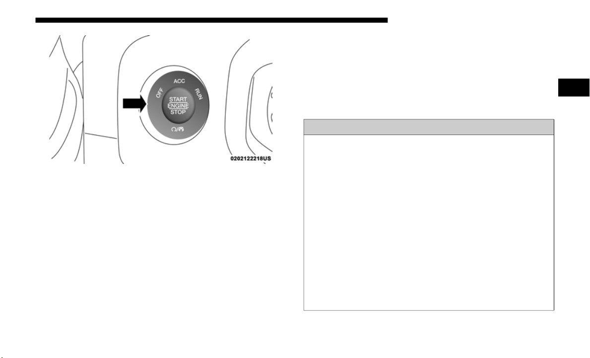
START/STOP Ignition Button
The push button ignition can be placed in the following
modes:
OFF
• T
h
e engine is stopped.
• Some el
ectrical devices (e.g. Central locking, alarm, etc.)
are ava
ilable.
ACC
• E
ngine is not started.
• Some el
ectrical devices are available.
RUN
• Driv
ing position.
• All ele
ctrical devices are available.
START
• Th
e engine will start.
WARNING!
• When exiting the vehicle, always remove the key fob
from the
vehicle and lock your vehicle.
• Never leave children alone in a vehicle, or with access
to an un
locked vehicle.
• Allowing children to be in a vehicle unattended is
dangerous
for a number of reasons. A child or others
could be seriously or fatally injured. Children should
be warned not to touch the parking brake, brake pedal
or the gear selector.
• Do not leave the key fob in or near the vehicle, or in a
locatio
n accessible to children, and do not leave the igni-
tion of a vehicle equipped with Keyless Enter-N-Go in
t
he ON/RUN
mode. A child could operate power
windows, other controls, or move the vehicle.
2

24 GETTING TO KNOW YOUR VEHICLE
(Continued)
NOTE:
Refer to "Starting The Engine," in "Starting And Operating"
for fur
ther information.
Vehicle On Message
When opening the driver's door when the ignition is in the
ON/RUN mode (engine not running), a chime will sound to
remind you to place the ignition in the OFF mode. In addi
-
tion to the chime, the message will display “Ignition Or
Accesso
ry On” in the cluster.
NOTE:
The power window switches will remain active up to ten
minutes
after the ignition is cycled to the OFF mode.
Opening either front door will cancel this feature. The time
for this feature is programmable.
• Do not leave children or animals inside parked vehicles
in hot
weather. Interior heat build-up may cause
serious injury or death.
CAUTION!
An unlocked vehicle is an invitation for thieves. Always
remove ke
y fob from the vehicle and lock all doors when
leaving the vehicle unattended.
WARNING! (Continued)
WARNING!
• Before exiting a vehicle, always come to a complete stop,
then s
hift the automatic transmission into PARK, apply
the parking brake, place the engine in the OFF position,
remove the key fob from the vehicle and lock your
vehicle. If equipped with Keyless Enter-N-Go, always
make sure the keyless ignition is in “OFF” position,
remove the key fob from the vehicle and lock the vehicle.
• Never leave children alone in a vehicle, or with access
to an u
nlocked vehicle.
• Allowing children to be in a vehicle unattended is
dangerou
s for a number of reasons. A child or others
could be seriously or fatally injured. Children should
be warned not to touch the parking brake, brake pedal
or the gear selector.
GETTING TO KNOW YOUR VEHICLE 25
REMOTE STARTING SYSTEM — IF EQUIPPED
This system uses the key fob to start the engine
conveniently from outside the vehicle while still
maintain
ing security. The system has a range of
328
ft (100 m).
The Remote Starting System also activates the Climate
Control,
vented seats (if equipped) in temperatures above
80° F (26.7° C), and the heated seats (if equipped), and heated
steering wheel (if equipped) in temperatures below 40° F
(4.4° C). Refer to “Seats” in “Getting To Know Your Vehicle”
in this section for further information.
NOTE:
• T
he vehicle must be equipped with an automatic transmis-
sion to
be equipped with Remote Start.
• O
bstructions between the vehicle and key fob may reduce
this ra
nge.
• Do not leave the key fob in or near the vehicle, or in a
locatio
n accessible to children, and do not leave the igni-
tion of a vehicle equipped with Keyless Enter-N-Go in
t
he ON/RUN
mode. A child could operate power
windows, other controls, or move the vehicle.
• Do not leave children or animals inside parked vehicles
in hot w
eather. Interior heat build-up may cause
serious injury or death.
• Never remove the mechanical key while the vehicle is
moving, as
the steering wheel will automatically lock
as soon as the key is turned. This also applies to vehi
-
cles that are being towed.
CAUTION!
An unlocked vehicle is an invitation for thieves. Always
r
emove key
fob from the vehicle and lock all doors when
leaving the vehicle unattended.
WARNING! (Continued)
2

26 GETTING TO KNOW YOUR VEHICLE
How To Use Remote Start
• Push Remote Start button on the key fob twice within five
seconds. Pushing the Remote Start button a third time
shuts the engine off.
• To drive the vehicle, push unlock button, and place the
ignitio
n in the ON/RUN position.
• With remote start, the engine will only run for 15 minut
es
(timeout) unless the ignition key is placed in the ON/RUN
position.
• The vehicle must be started with the key after two consec-
utive
timeouts.
All of the following conditions must be met before the engine
will rem
ote start:
• Gear Selector in PARK
• Doors
closed
• Hood c
losed
• Swing Ga
te closed
• Hazard
switch off
• Brake s
witch inactive (brake pedal not pushed)
• Batte
ry at an acceptable charge level
• PANIC
button not pushed
• System
not disabled from previous remote start event
• Vehicl
e alarm system indicator flashing
• Ignitio
n in STOP/OFF position
• Fuel le
vel meets minimum requirement
• All re
movable doors must not be removed
• Malfun
ction indicator light not illuminated
WARNING!
• Do not start or run an engine in a closed garage or
confine
d area. Exhaust gas contains Carbon Monoxide
(CO) which is odorless and colorless. Carbon
Monoxide is poisonous and can cause serious injury or
death when inhaled.
• Keep key fobs away from children. Operation of the
Remote
Start System, windows, door locks or other
controls could cause serious injury or death.

GETTING TO KNOW YOUR VEHICLE 27
Remote Start Cancel Message — If Equipped
The following messages will display in the instrument
cluster if the vehicle fails to remote start or exits remote start
prematurely:
• Remote Start Cancelled — Door Open
• Remote
Start Cancelled — Hood Open
• Remote
Start Cancelled — Fuel Low
• Remote
Start Cancelled — Swing Gate Open
• Remote
Start Cancelled — Time Expired
• Remote
Start Disabled — Start Vehicle To Reset
The me
ssage will stay active until the ignition is placed in the
ON/RUN p
osition.
To Enter Remote Start Mode
Push and release the Remote Start button on the key fob
twice within five seconds. The vehicle doors will lock, the
turn signals will flash twice, and the horn will chirp twice.
Then the engine will start, and the vehicle will remain in the
Remote Start mode for a 15-minute cycle.
NOTE:
• I
f an engine fault is present or fuel level is low, the vehicle
will st
art and then shut down in 10 seconds.
• The park lamps will turn on and remain on during Remote
Start
mode.
• For security, power window operation is disabled when
the ve
hicle is in the Remote Start mode.
• The engine can be started two consecutive times (two
15-min
ute cycles) with the key fob. However, the ignition
must be placed in the ON/RUN position before you can
repeat the start sequence for a third cycle.
To Exit Remote Start Mode Without Driving The
Vehicle
Push and release the Remote Start button one time or allow
the remote start cycle to complete the entire 15-minute cycle.
NOTE:
To avoid unintentional shutdowns, the system will disable
t
he one
time push of the Remote Start button for two seconds
after receiving a valid Remote Start request.
2

28 GETTING TO KNOW YOUR VEHICLE
To Exit Remote Start Mode And Drive The Vehicle
Before the end of 15-minute cycle, push and release the
unlock button on the key fob to unlock the doors, or unlock
the vehicle using Keyless Enter-N-Go — Passive Entry via
the door handles, and disarm the vehicle security alarm (if
equipped). Then, prior to the end of the 15-minute cycle,
push and release the START/STOP button.
NOTE:
For vehicles equipped with the Keyless Enter-N-Go —
P
assive
Entry feature, the message “Remote Start Active —
Push Start Button” will display in the instrument cluster
display until you push the ignition START button.
Remote Start Comfort Systems — If Equipped
When Remote Start is activated, the Climate Controls may
activate the heated seats (if equipped) and heated steering
wheel (if equipped) in temperatures below 40° F (4.4° C).
These features will stay on through the duration of Remote
Start or until the ignition switch is cycled to the ON/RUN
position.
General Information
The following regulatory statement applies to all radio
frequency (RF) devices equipped in this vehicle:
This device complies with Part 15 of the FCC Rules and with
Industr
y Canada license-exempt RSS standard(s). Operation
is subject to the following two conditions:
1. This device may not cause harmful interference, and
2. This
device must accept any interference received,
includ
ing interference that may cause undesired opera-
tion.
NOTE:
Changes or modifications not expressly approved by the
p
arty re
sponsible for compliance could void the user’s
authority to operate the equipment.

GETTING TO KNOW YOUR VEHICLE 29
SENTRY KEY
The Sentry Key Immobilizer system prevents unauthorized
vehicle operation by disabling the engine. The system does
not need to be armed or activated. Operation is automatic,
regardless of whether the vehicle is locked or unlocked.
The system uses a key fob, keyless push button ignition and
a RF rec
eiver to prevent unauthorized vehicle operation.
Therefore, only key fobs that are programmed to the vehicle
can be used to start and operate the vehicle. The system
cannot reprogram a key fob obtained from another vehicle.
After turning the ignition switch to the ON/RUN position,
the veh
icle security light will turn on for three seconds for a
bulb check. If the light remains on after the bulb check, it
indicates that there is a problem with the electronics. In addi-
tion, if the light begins to flash after the bulb check, it indi-
cates that someone attempted to start the engine with an
i
nvalid
key fob. In the event that a valid key fob is used to
start the engine but there is an issue with the vehicle elec-
tronics, the engine will start and shut off after two seconds.
If the vehicle security light turns on during normal vehicle
operati
on (vehicle running for longer than ten seconds), it
indicates that there is a fault in the electronics. Should this
occur, have the vehicle serviced as soon as possible by an
authorized dealer.
All of the key fobs provided with your new vehicle have
been pr
ogrammed to the vehicle electronics.
Replacement Keys
NOTE:
Only key fobs that are programmed to the vehicle electronics
can be
used to start and operate the vehicle. Once a key fob
is programmed to a vehicle, it cannot be programmed to any
other vehicle.
CAUTION!
The Sentry Key Immobilizer system is not compatible
with som
e aftermarket remote starting systems. Use of
these systems may result in vehicle starting problems
and loss of security protection.
CAUTION!
• Always remove the key fobs from the vehicle and lock
all doors when leaving the vehicle unattended.
• For vehicles equipped with Keyless Enter-N-Go —
Ignition
, always remember to place the ignition in the
OFF position.
2

30 GETTING TO KNOW YOUR VEHICLE
NOTE:
Duplication of key fobs may be performed at an authorized
dealer.
This procedure consists of programming a blank key
fob to the vehicle electronics. A blank key fob is one that has
never been programmed.
When having the Sentry Key Immobilizer System serviced,
bring al
l vehicle keys with you to an authorized dealer.
General Information
The following regulatory statement applies to all radio
frequency (RF) devices equipped in this vehicle:
This device complies with Part 15 of the FCC Rules and with
Industr
y Canada license-exempt RSS standard(s). Operation
is subject to the following two conditions:
1. This device may not cause harmful interference, and
2. This
device must accept any interference received,
includ
ing interference that may cause undesired operation.
NOTE:
Changes or modifications not expressly approved by the
party re
sponsible for compliance could void the user’s
authority to operate the equipment.
VEHICLE SECURITY ALARM — IF EQUIPPED
The vehicle security alarm monitors the vehicle doors for
unauthorized entry and the ignition switch for unauthorized
operation. When the alarm is activated, the interior switches
for door locks are disabled. The vehicle security alarm
provides both audible and visible signals. If something trig
-
gers the alarm, the vehicle security alarm will provide the
followin
g audible and visible signals: the horn will pulse, the
park lamps and/or turn signals will flash, and the vehicle
security light in the instrument cluster will flash.
To Arm The System
Follow these steps to arm the vehicle security alarm:
1. Make sure the vehicle’s ignition is cycled to the “OFF”
positi
on (refer to "Starting The Engine" in "Starting And
Operating" for further information).
2. Perform one of the following methods to lock the vehicle:
• Push l
ock on the interior power door lock switch with
the dr
iver and/or passenger door open.

GETTING TO KNOW YOUR VEHICLE 31
• Push the lock button on the exterior Passive Entry Door
Handle with a valid key fob available in the same exte-
rior zone (refer to "Keyless Enter-N-Go — Passive
E
ntry" i
n "Getting To Know Your Vehicle" for further
information).
• Push the lock button on the key fob.
3. If a
ny doors are open, close them.
To Disarm The System
The vehicle security alarm can be disarmed using any of the
following methods:
• Push the unlock button on the key fob.
• Grasp
the Passive Entry Unlock Door Handle (if equipped,
refer
to "Keyless Enter-N-Go — Passive Entry" in "Getting
To Know Your Vehicle" for further information).
• Cycle the vehicle ignition system out of the OFF position.
NOTE:
• T
he driver's door key cylinder cannot arm or disarm the
vehicl
e security alarm.
• When the vehicle security alarm is armed, the interior
power d
oor lock switches will not unlock the doors.
The vehicle security alarm is designed to protect your
vehicle
. However, you can create conditions where the
system will give you a false alarm. If one of the previously
described arming sequences has occurred, the vehicle secu
-
rity alarm will arm regardless of whether you are in the
v
ehicle
or not. If you remain in the vehicle and open a door,
the alarm will sound. If this occurs, disarm the vehicle secu
-
rity alarm.
If the vehicle security alarm is armed and the battery
becomes
disconnected, the vehicle security alarm will
remain armed when the battery is reconnected; the exterior
lights will flash, and the horn will sound. If this occurs,
disarm the vehicle security alarm.
Rearming Of The System
If something triggers the alarm, and no action is taken to
disarm it, the vehicle security alarm will turn the horn off
after 29 seconds, 5 seconds between cycles, up to 8 cycles if
the trigger remains active and then the vehicle security alarm
will rearm itself.
2
32 GETTING TO KNOW YOUR VEHICLE
DOORS
Manual Door Locks
All doors are equipped with an interior rocker-type door
lock lever. To lock a door when leaving your vehicle, push
the rocker lever forward to the lock position and close the
door. To unlock the door, push the rocker lever rearward.
Manual Door Lock
NOTE:
The mechanical flip key can be used to lock or unlock the
d
oors, s
wing gate, glove compartment, and console storage.
CAUTION!
Careless handling and storage of the removable door
panels m
ay damage the seals, causing water to leak into
the vehicle’s interior.
GETTING TO KNOW YOUR VEHICLE 33
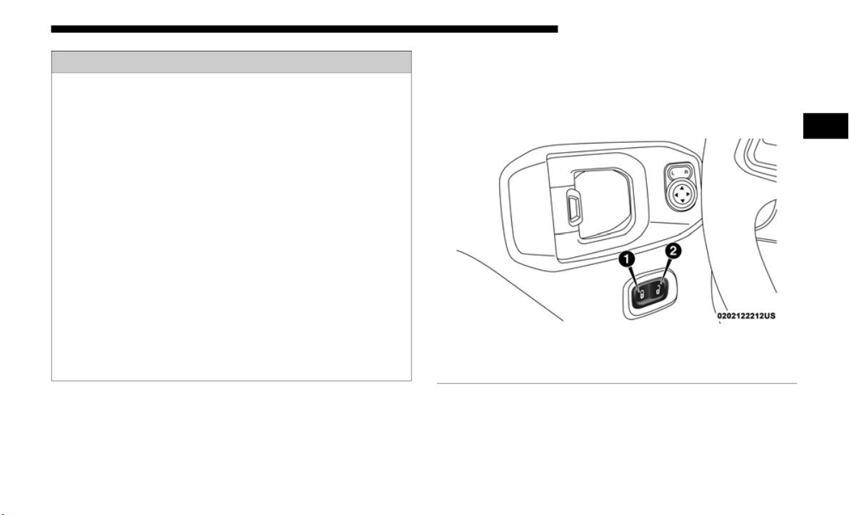
Power Door Locks — If Equipped
The power door lock switch is located on each front door
panel. Push the switch forward to lock the doors, and rear-
ward to unlock the doors.
Power Door Lock Switch
WARNING!
• For personal security reasons and safety in a collision,
lock the
vehicle doors when you drive, as well as when
you park and exit the vehicle.
• When exiting the vehicle, always switch off the ignition
and rem
ove the key from the vehicle. Unsupervised use
of vehicle equipment may cause severe personal inju
-
ries and death.
• N
ever leave children alone in a vehicle, or with access
to an un
locked vehicle.
• Allowing children to be in a vehicle unattended is
dangerous
for a number of reasons. A child or others
could be seriously or fatally injured. Children should
be warned not to touch the parking brake, brake pedal
or the gear selector.
• Do not leave the key fob in or near the vehicle or in a
location
accessible to children. A child could operate
power windows, other controls, or move the vehicle.
1 — Lock Button
2 — Unlock Button
2

34 GETTING TO KNOW YOUR VEHICLE
Keyless Enter-N-Go — Passive Entry (If Equipped)
The Passive Entry system is a feature that allows you to lock
and unlock the vehicle’s door(s) and swing gate without
having to push the key fob lock or unlock buttons.
NOTE:
• Passive Entry may be programmed ON/OFF; refer to “Ucon-
nect Set
tings” in “Multimedia” for further information.
• T
he key fob may not be detected by the vehicle passive
entry s
ystem if it is located next to a mobile phone, laptop,
or other electronic device; these devices may interfere with
the key fob’s wireless signal and prevent the passive entry
system from locking/unlocking the vehicle.
• Passive Entry Unlock initiates illuminated approach (Low
Beams,
License Plate Lamp, Position Lamps) for which-
ever time duration is set between 0, 30 (default), 60 or 90
s
econds
. Passive Entry Unlock also initiates two flashes of
the turn signal lamps.
• If wearing gloves on your hands, or if it has been raining/
snowin
g on the Passive Entry door handle, the unlock sensi-
tivity can be affected, resulting in a slower response time.
• I
f the vehicle is unlocked by Passive Entry and no door is
opened
within 60 seconds, the vehicle will re-lock and if
equipped will arm the security alarm.
WARNING!
• For personal security reasons and safety in a collision,
lock th
e vehicle doors when you drive, as well as when
you park and exit the vehicle.
• When exiting the vehicle, always switch off the ignition
and re
move the key from the vehicle. Unsupervised use
of vehicle equipment may cause severe personal inju
-
ries and death.
• N
ever leave children alone in a vehicle, or with access
to an u
nlocked vehicle.
• Allowing children to be in a vehicle unattended is
dangerou
s for a number of reasons. A child or others
could be seriously or fatally injured. Children should
be warned not to touch the parking brake, brake pedal
or the gear selector.
• Do not leave the key fob in or near the vehicle or in a
location
accessible to children. A child could operate
power windows, other controls, or move the vehicle.

GETTING TO KNOW YOUR VEHICLE 35
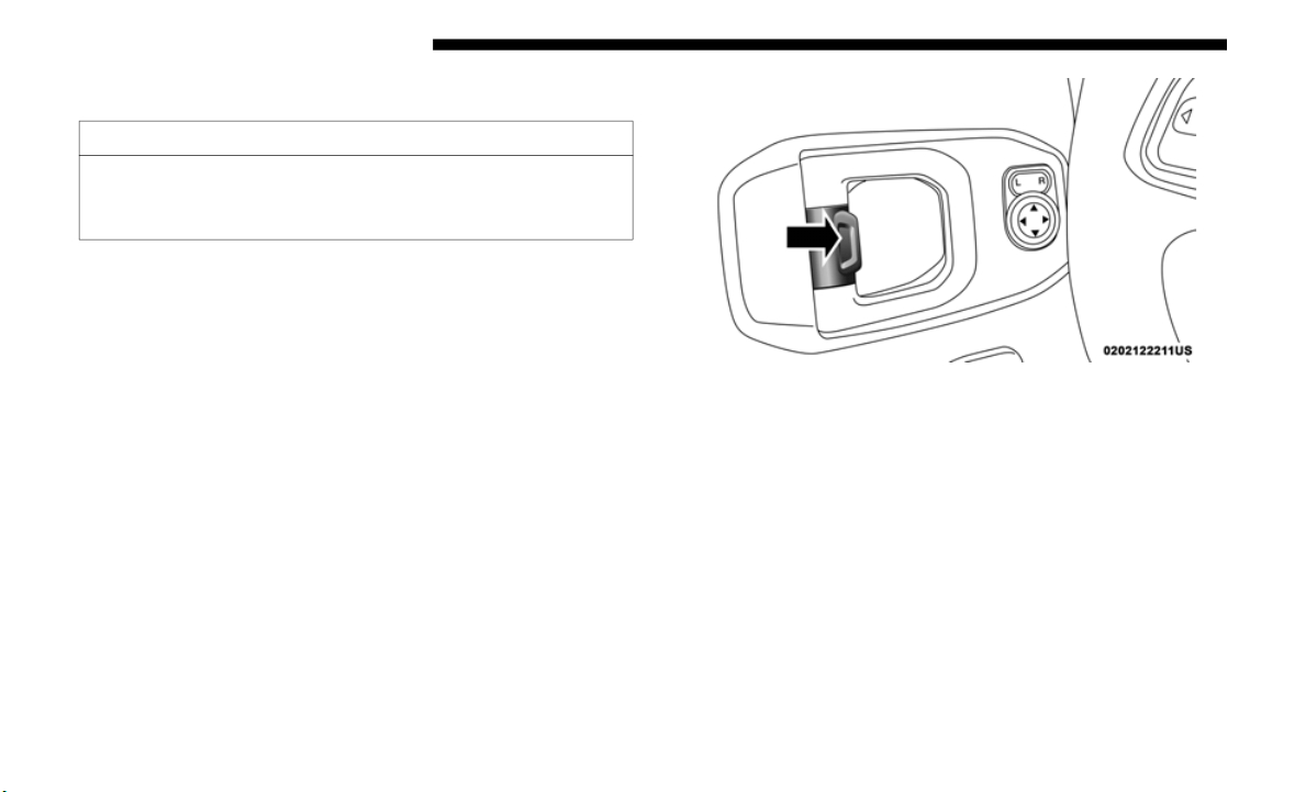
To Unlock From The Driver Side
With a valid Passive Entry key fob within 5 ft (1.5 m) of the
driver's
door handle, grab the front driver door handle to
unlock the driver's door automatically.
Grab The Door Handle To Unlock
NOTE:
If “1st Press Of Key Fob Unlock” is programmed all doors
will unlo
ck when you grab hold of the front driver’s door
handle. To select between “Unlock Driver Door 1st Press”
and “Unlock All Doors 1st Press,” refer to “Uconnect
Settings” in “Multimedia” for further information.
To Unlock From The Passenger Side
With a valid Passive Entry key fob within 5 ft (1.5 m) of the
passenger
door handle, grab the front passenger door handle
to unlock all doors and the swing gate automatically.
NOTE:
All doors will unlock when the front passenger door handle
is grabbe
d regardless of the driver’s door unlock preference
setting (“Unlock Driver Door 1st Press” or “Unlock All
Doors 1st Press”).
Preventing Inadvertent Locking Of Passive Entry Key Fob
In Vehic
le (FOBIK-Safe)
To minimize the possibility of unintentionally locking a
Passive
Entry key fob inside your vehicle, the Passive Entry
system is equipped with an automatic door unlock feature
which will function only if the ignition switch is in the OFF
position.
2

36 GETTING TO KNOW YOUR VEHICLE
FOBIK-Safe only executes in vehicles with passive entry.
There are three situations that trigger a FOBIK-Safe search in
any passive entry vehicle:
• A lock request is made by a valid Passive Entry key fob
while a
door is open.
• A lock request is made by the Passive Entry door handle
while a
door is open.
• A lock request is made by the door panel switch while the
door is
open.
When any of these situations occur, after all open doors are
shut, th
e FOBIK-Safe search will be executed. If it finds a
Passive Entry key fob inside the car, the car will unlock and
alert the customer. If Passive Entry is disabled using Ucon
-
nect System, the key protection described in "Preventing
I
nadvert
ent Locking of Passive Entry Key Fob in Vehicle"
remains active/functional.
NOTE:
The vehicle will only unlock the doors during a FOBIK-Safe
operatio
n when a valid Passive Entry key fob is detected
inside the vehicle. The vehicle will not unlock the doors
when any of the following conditions are true:
• A second valid passive entry key fob is detected outside of
the veh
icle (within 5ft of a passive entry door handle).
• The doors are manually locked using the door lock knobs.
• Three a
ttempts are made to lock the doors using the door
panel s
witch and then close the doors.
To Lock The Vehicle’s Doors And Swing Gate
With one of the vehicle’s Passive Entry key fob within 5 ft
(1.5 m) o
f the driver or passenger front door handles,
pushing t
he passive entry lock button will lock the vehicle
doors and the swing gate.
Push The Door Handle Button To Lock
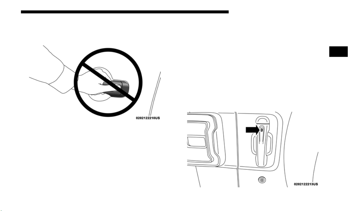
GETTING TO KNOW YOUR VEHICLE 37
NOTE:
DO NOT grab the door handle, when pushing the door
handle l
ock button. This could unlock the door(s).
DO NOT Grab The Door Handle When Locking
The vehicle doors can also be locked by using the lock button
located
on the vehicle’s interior door panel.
To Unlock/Enter The Swing Gate
The Swing Gate passive entry unlock feature is built into the
Swing Gate
handle. With a valid Passive Entry key fob
within 5 ft (1.5 m) of the Swing Gate handle, grab the Swing
Gate han
dle to unlock the Swing Gate automatically, and
pull the Swing Gate to open.
NOTE:
If “Unlock All Doors 1st Press” is programmed all doors &
the swing
gate will unlock when you grab hold of the swing
gate handle. To select between “Unlock Driver Door 1st
Press” and “Unlock All Doors 1st Press,” refer to “Uconnect
Settings” in “Multimedia” for further information.
Swing Gate Passive Entry Location
2

38 GETTING TO KNOW YOUR VEHICLE
To Lock The Swing Gate
With a valid Passive Entry key fob within 5 ft (1.5 m) of the
Swing Gat
e handle, pushing the passive entry lock button
will lock the vehicle doors and the swing gate.
NOTE:
• After pushing the door handle button, you must wait two
second
s before you can lock or unlock the doors, using any
Passive Entry door handle. This is done to allow you to
check if the vehicle is locked by pulling the door handle
without the vehicle reacting and unlocking.
• If Passive Entry is disabled using Uconnect System, the
key prot
ection described in "Preventing Inadvertent
Locking of Passive Entry Key Fob in Vehicle" remains
active/functional.
• The Passive Entry system will not operate if the key fob
batter
y is dead.
General Information
The following regulatory statement applies to all radio
frequen
cy (RF) devices equipped in this vehicle:
This device complies with Part 15 of the FCC Rules and with
I
n
dustr
y Canada license-exempt RSS standard(s). Operation
is subject to the following two conditions:
1. This device may not cause harmful interference, and
2. This
device must accept any interference received,
includ
ing interference that may cause undesired opera-
tion.
NOTE:
Changes or modifications not expressly approved by the
p
arty re
sponsible for compliance could void the user’s
authority to operate the equipment.

GETTING TO KNOW YOUR VEHICLE 39
Child-Protection Door Lock System — Rear Doors
To provide a safer environment for small children riding in
the rear seats, the rear doors are equipped with a
Child-Protection Door Lock system.
To use the system, open each rear door, use a flat blade
screwdriv
er (or emergency key) and rotate the dial to the
lock or unlock position.
Child Protection Door Lock Function
NOTE:
• When the child lock system is engaged, the door can be
opened
only by using the outside door handle even
though the inside door lock is in the unlocked position.
• After engaging or disengaging the Child-Protection Door
Lock syst
em, always test the door from the inside to make
certain it is in the desired position.
• For emergency exit with the system engaged, move the lock
lever rear
ward (located on the door trim panel), roll down the
window and open the door with the outside door handle.
NOTE:
Always use this device when carrying children. After
e
ngaging th
e child lock on both rear doors, check for effec-
tive engagement by trying to open a door with the internal
handle.
Once the Child-Protection Door Lock system is
engaged, it is impossible to open the doors from inside the
vehicle. Before getting out of the car, be sure to check that
there is no one left inside.
WARNING!
Avoid trapping anyone in a vehicle in a collision.
Remember
that the rear doors can only be opened from the
outside when the Child-Protection locks are engaged
(locked).
2
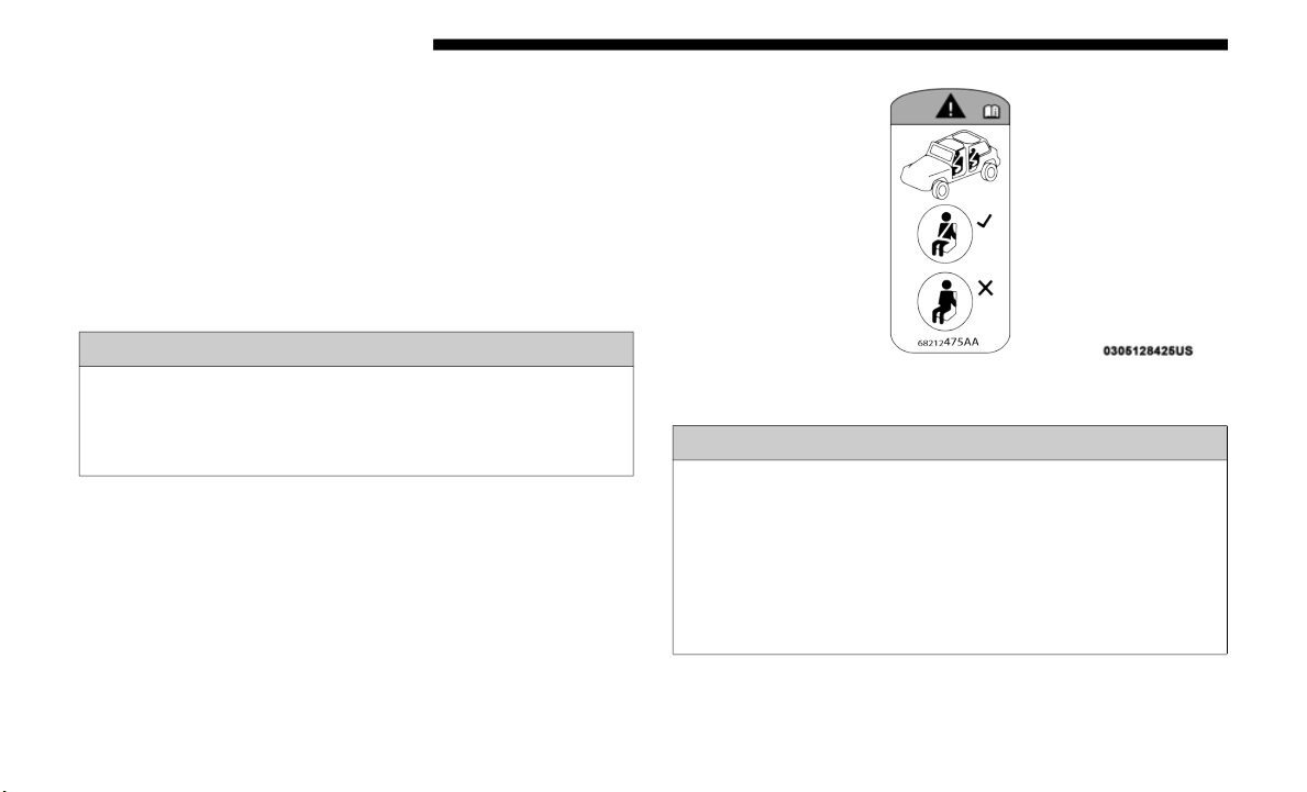
40 GETTING TO KNOW YOUR VEHICLE
Automatic Door Locks — If Equipped
The auto door lock feature default condition is enabled.
When enabled, the door locks will lock automatically when
the vehicle's speed exceeds 15
mph (24 km/h). The auto door
lock feat
ure can be enabled or disabled by an authorized
dealer per written request of the customer. Please see an
authorized dealer for service.
Front Door Removal
Door Removal Warning Label
WARNING!
Do not drive your vehicle on public roads with the doors
removed as
you will lose the protection they can provide.
This procedure is furnished for use during off-road
operation only.
WARNING!
• All occupants must wear seat belts during off-road
operation
with doors removed. Refer to “Off-Road
Driving Tips” in “Starting And Operating” for further
information.
• Do not store detached doors inside of the vehicle, as
they may
cause personal injury in the event of an acci-
dent.

GETTING TO KNOW YOUR VEHICLE 41
NOTE:
• Doors are heavy; use caution when removing them.
• Hinge pi
n can break if overtightened during door reinstall
(Max To
rque: 7.5 ft· lb / 10 N·m). Refer to “Off-Road
Driving
Tips” in “Starting And Operating” for further
information.
• When front doors are removed, the message “Blind Spot
Alert T
emporarily Unavailable” will display in the instru-
ment cluster display. Power Mirrors and Power Door
L
ocks will
also be unavailable.
1. Roll down the glass window to prevent any damage.
2. Remov
e the hinge pin screws from the upper and lower
outside
hinges (using a #T50 Torx head driver).
NOTE:
The hinge pin screws and nuts can be stowed in the rear
c
argo tra
y located under the rear loadfloor.
Hinge Pin Screw
2
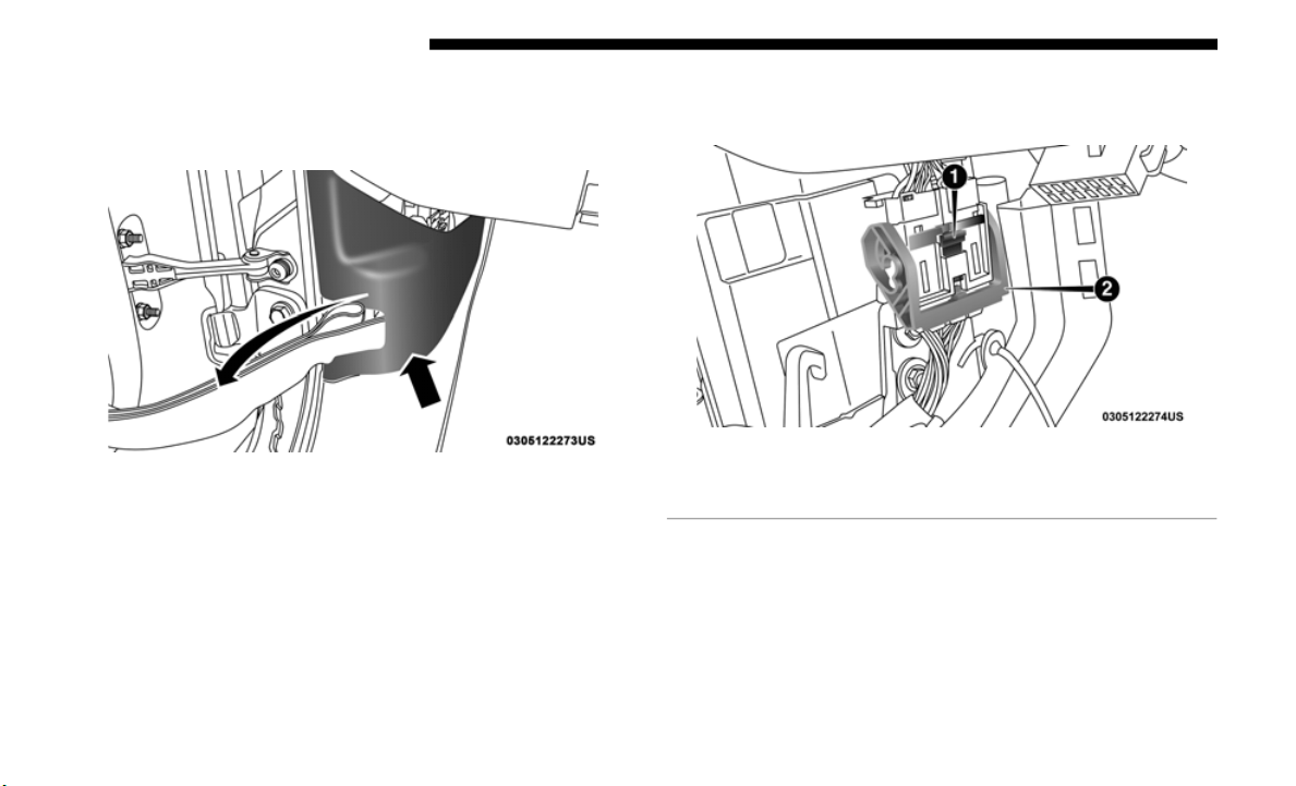
42 GETTING TO KNOW YOUR VEHICLE
3. Remove the plastic wiring access door under the instru-
ment panel by sliding the plastic panel along the door
frame to
ward the seats until the tabs are detached.
Wiring Access Door
NOTE:
Do not pry back to open, as this will break the plastic cover.
4. P
ull up on the red locking tab to unlock the wiring
harness
.
Closed Wiring Harness
1 – Locking Tab
2 – Wiring Harness
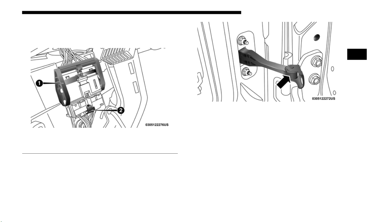
GETTING TO KNOW YOUR VEHICLE 43
5. Push and hold down the black security tab under the
wiring harness, and lift the harness into the open posi-
tion.
Open Wiring Harness
6. W
ith the wiring harness open, pull downward on the
wiring co
nnector to unplug. Store wiring connector in the
lower door basket.
7. Remove the check screw from the center door check
(using a
#T40 Torx head driver).
Door Check (Detached)
8. W
ith the door open, lift the door with the help of another
person,
to clear the hinge pins from their hinges and
remove the door.
To reinstall the door(s), perform the previous steps in the
opposite
order.
NOTE:
The upper hinge has a longer pin, which can be used to assist
i
n guidin
g the door into place when reinstalling.
1 – Wiring Harness
2 – Security Tab
2
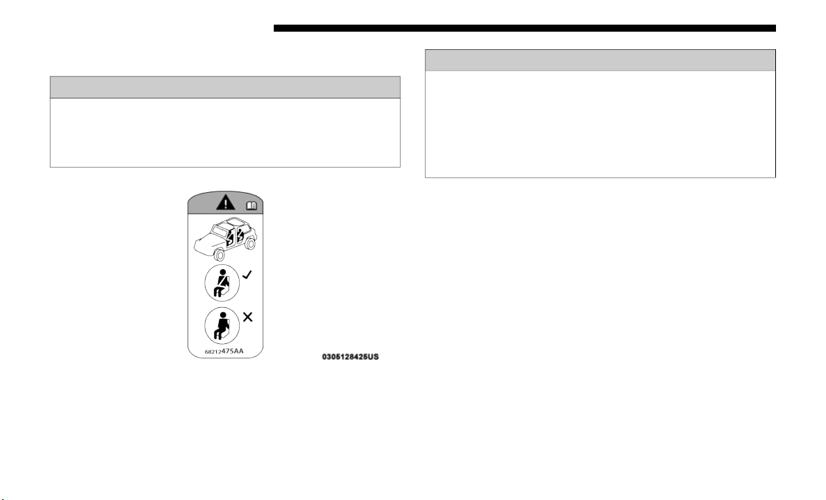
44 GETTING TO KNOW YOUR VEHICLE
Rear Door Removal (Four-Door Models)
Door Removal Warning Label
NOTE:
• Doors are heavy; use caution when removing them.
• Hinge pi
n can break if overtightened during door reinstall
(Max To
rque: 7.5 ft· lb / 10 N·m). Refer to “Off-Road
Driving T
ips” in “Starting And Operating” for further
information.
1. Roll down the glass window to prevent any damage.
2. Remov
e the hinge pin screws from the upper and lower
outside
hinges (using a #T50 Torx head driver).
WARNING!
Do not drive your vehicle on public roads with the doors
removed as
you will lose the protection they can provide.
This procedure is furnished for use during off-road
operation only.
WARNING!
• All occupants must wear seat belts during off-road
operation
with doors removed. Refer to “Off-Road
Driving Tips” in “Starting And Operating” for further
information.
• Do not store detached doors inside of the vehicle, as they
may cau
se personal injury in the event of an accident.
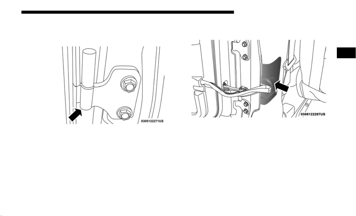
GETTING TO KNOW YOUR VEHICLE 45
NOTE:
The hinge pin screws and nuts can be stowed in the rear
cargo tra
y located under the rear load floor.
Hinge Pin Screw
3. Slide the front seat(s) fully forward.
4. Pry op
en and remove the plastic wiring access door from
the bot
tom of the B-pillar.
Wiring Access Door
2
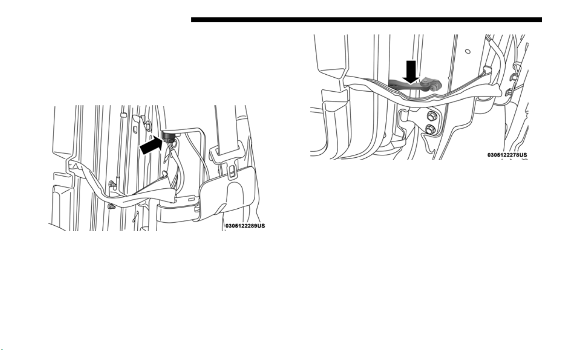
46 GETTING TO KNOW YOUR VEHICLE
5. Unplug the wiring connector.
NOTE:
Squeeze the tab on the base of the wiring harness. This will
u
nlock th
e connector tab, allowing the wiring connector to be
unplugged.
Wiring Connector
6. Remove the check screw from the center door check
(using a
#T40 Torx head driver).
Door Check (Attached)
7. With the door open, lift the door with the help of another
person,
to clear the hinge pins from their hinges and
remove the door.
To reinstall the door(s), perform the previous steps in the
reverse
order.
NOTE:
The upper hinge has a longer pin, which can be used to assist
i
n guidin
g the door into place when reinstalling.
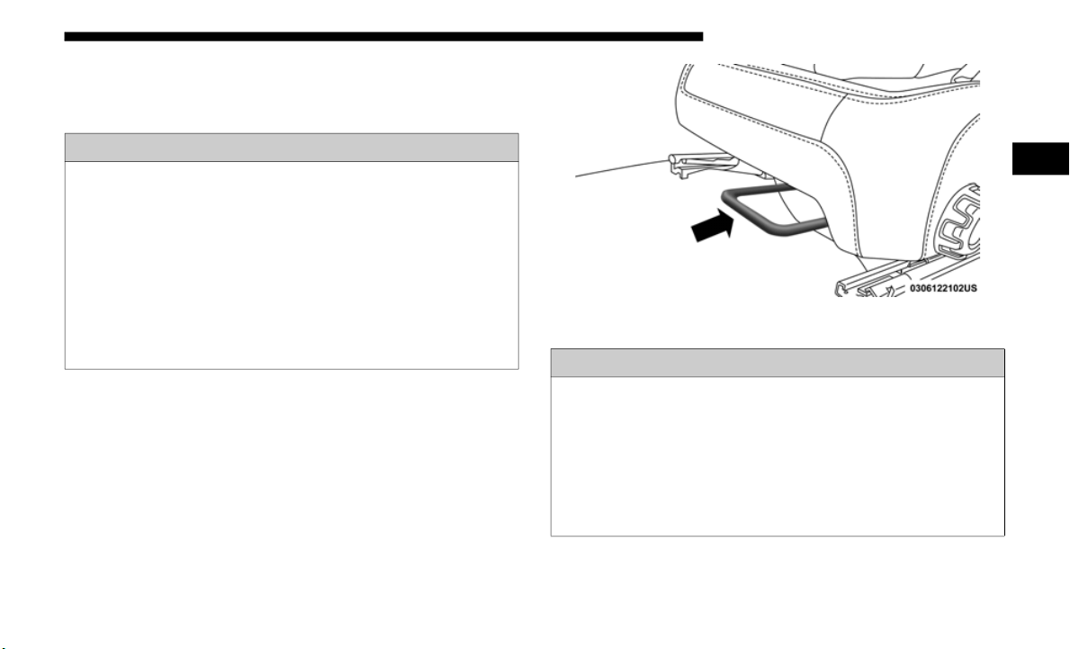
GETTING TO KNOW YOUR VEHICLE 47
SEATS
Seats are a part of the Occupant Restraint System of the vehicle.
Manual Front Seats
Front Seat Adjustment
The seat can be adjusted forward or rearward by using a bar
located
by the front of the seat cushion, near the floor. While
sitting in the seat, lift up on the bar located under the seat
cushion and move the seat forward or rearward. Release the
bar once you have reached the desired position. Then, using
body pressure, move forward and rearward on the seat to be
sure that the seat adjusters have latched.
Adjustment Bar Location
WARNING!
• It is dangerous to ride in a cargo area, inside or outside
of a vehi
cle. In a collision, people riding in these areas
are more likely to be seriously injured or killed.
• Do not allow people to ride in any area of your vehicle
that is
not equipped with seats and seat belts. In a colli-
sion, people riding in these areas are more likely to be
s
eriously
injured or killed.
• Be sure everyone in your vehicle is in a seat and using
a seat
belt properly.
WARNING!
• Adjusting a seat while driving may be dangerous.
Moving a s
eat while driving could result in loss of
control which could cause a collision and serious injury
or death.
• Seats should be adjusted before fastening the seat belts
and whi
le the vehicle is parked. Serious injury or death
could result from a poorly adjusted seat belt.
2
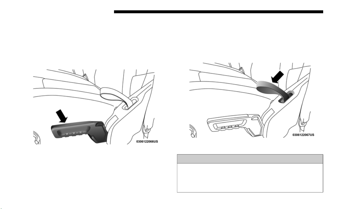
48 GETTING TO KNOW YOUR VEHICLE
Manual Seat Height Adjustment
The driver's seat height can be raised or lowered by using the
ratcheti
ng handle, located on the outboard side of the seat.
Pull upward on the handle to raise the seat, push downward
on the handle to lower the seat. Several strokes may be neces
-
sary to achieve the desired position.
Seat Height Adjustment
Front Seatback Recline
To recline the seat, pull on the recline strap and lean forward
o
r backward, depending on the direction you would like the
seatback to move. Release the strap when the desired posi
-
tion is reached and the seatback will lock into place.
Recline Strap
WARNING!
Do not ride with the seatback reclined so that the
shoulder
belt is no longer resting against your chest. In a
collision you could slide under the seat belt, which could
result in serious injury or death.
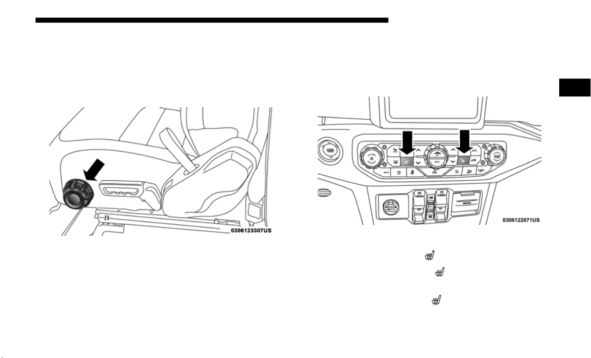
GETTING TO KNOW YOUR VEHICLE 49
Lumbar Support
The lumbar control knob is located on the outboard side of
the fron
t driver seat. Rotate the control forward to increase
and rearward to decrease the desired amount of lumbar
support.
Lumbar Control Knob
Heated Seats — If Equipped
The heated seats control buttons are located on the center
instrument panel below the touchscreen, and are also located
within the climate or controls screen of the touchscreen.
Heated Seat Buttons
• Push the heated seat button once to
turn the HI setting on.
• Push the heated seat button a seco
nd time to turn the
MED setting on.
• P
ush the heated seat button a thir
d time to turn the LO
setting on.
2
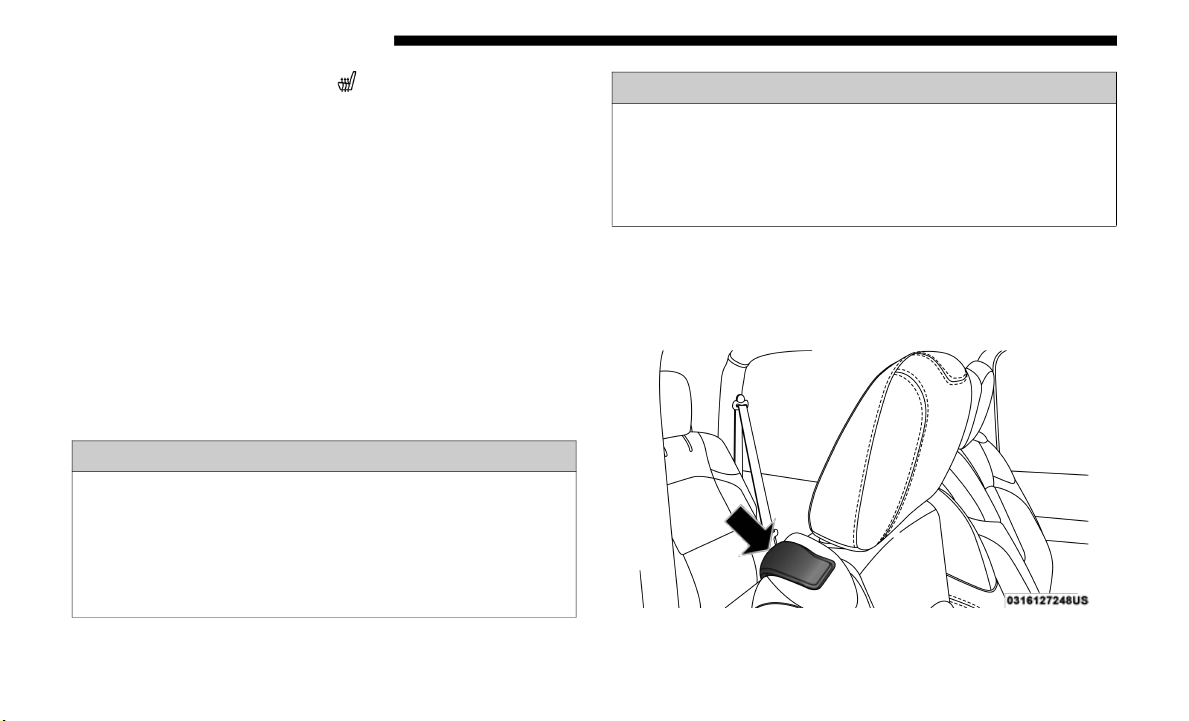
50 GETTING TO KNOW YOUR VEHICLE
(Continued)
• Push the heated seat button a fourth time to turn the
heating elements off.
NOTE:
• T
he engine must be running for the heated seats to operate.
• The lev
el of heat selected will stay on until the operator
changes
it.
Vehicles Equipped With Remote Start
On models that are equipped with remote start, the driver’s
s
eat can
be programmed to come on during a remote start.
This feature can be programmed through the Uconnect
system. R
efer to “Uconnect Settings” in “Multimedia” for
further information.
Front Passenger Easy Entry Seat — Two Door Models
Pull upward on the easy entry lever located on the outboard
side of the seat back, and slide the entire seat forward.
Easy Entry Lever
WARNING!
• Persons who are unable to feel pain to the skin because
of advanc
ed age, chronic illness, diabetes, spinal cord
injury, medication, alcohol use, exhaustion or other
physical condition must exercise care when using the
seat heater. It may cause burns even at low tempera
-
tures, especially if used for long periods of time.
• Do not place anything on the seat or seatback that insu-
lates against heat, such as a blanket or cushion. This
may cause
the seat heater to overheat. Sitting in a seat
that has been overheated could cause serious burns due
to the increased surface temperature of the seat.
WARNING! (Continued)

GETTING TO KNOW YOUR VEHICLE 51
To return the seat to a sitting position, fold the seatback
upright until it locks and push the seat rearward until the
track locks.
NOTE:
• The front passenger seats have a track memory, which
return
s the seat to its original position.
• The recline strap and easy entry lever should not be used
during
the automatic returning of the seat to its sitting
position.
60/40 Split Folding Rear Seat — Four Door Models
To provide additional storage area, each rear seat can be
folded flat to allow for extended cargo space.
NOTE:
• B
e sure that the front seats are fully upright and positioned
forward
. This will allow the rear seat to fold down easily.
• The center head restraints must be in the lowest position to
avoid
contact with the center console when folding the
seat.
To Fold Down The Rear Seat
There are two release levers located on each upper outboard
side of
the rear seat. The larger of the two release levers folds
down the seat and the head restraint simultaneously. The
smaller lever folds down the head restraint independently
for improved visibility.
WARNING!
• It is extremely dangerous to ride in a cargo area, inside
or outsi
de of a vehicle. In a collision, people riding in
these areas are more likely to be seriously injured or
killed.
• Do not allow people to ride in any area of your vehicle
that i
s not equipped with seats and seat belts.
• Be sure everyone in your vehicle is in a seat and using
a seat
belt properly.
2
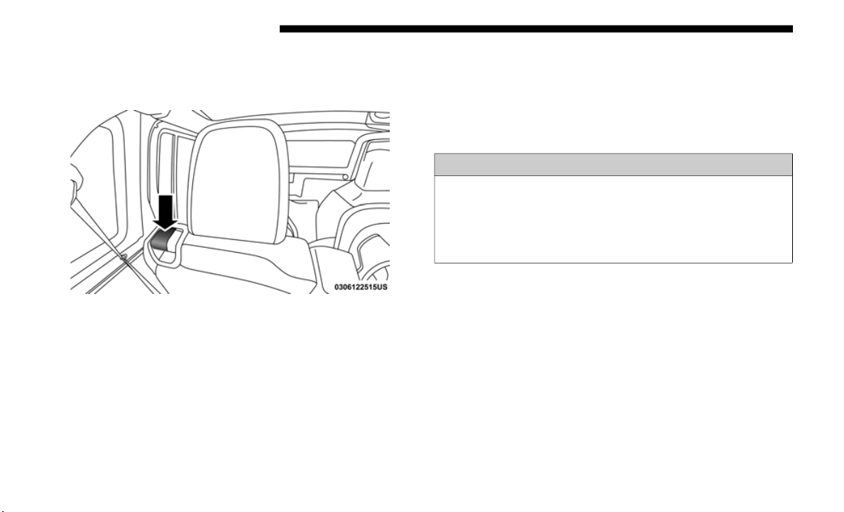
52 GETTING TO KNOW YOUR VEHICLE
To fold the seat, lift upward on the large release lever and
slowly fold down the seatback. The head restraint will fold
automatically with the seat when this lever is pulled.
Seatback Release Lever
NOTE:
You may experience deformation in the seat cushion from
the seat
belt buckles if the seats are left folded for an
extended period of time. This is normal. By simply opening
the seats to the open position, the seat cushion will return to
its normal shape over time.
To Raise The Rear Seat
Raise the seatback and lock it into place. Then, raise the head
restrain
t until it locks into place. If interference from the
cargo area prevents the seatback from fully locking, you will
have difficulty returning the seat to its proper position.
Fold And Tumble Rear Seat — Two Door Models
NOTE:
• Prior to folding the rear seat, it may be necessary to repo-
sition
the front seats.
• B
e sure that the front seats are fully upright and positioned
forward.
This will allow the rear seat to fold down easily.
WARNING!
Be certain that the seatback is securely locked into
position.
If the seatback is not securely locked into
position the seat will not provide the proper stability for
child seats and/or passengers. An improperly latched
seat could cause serious injury.
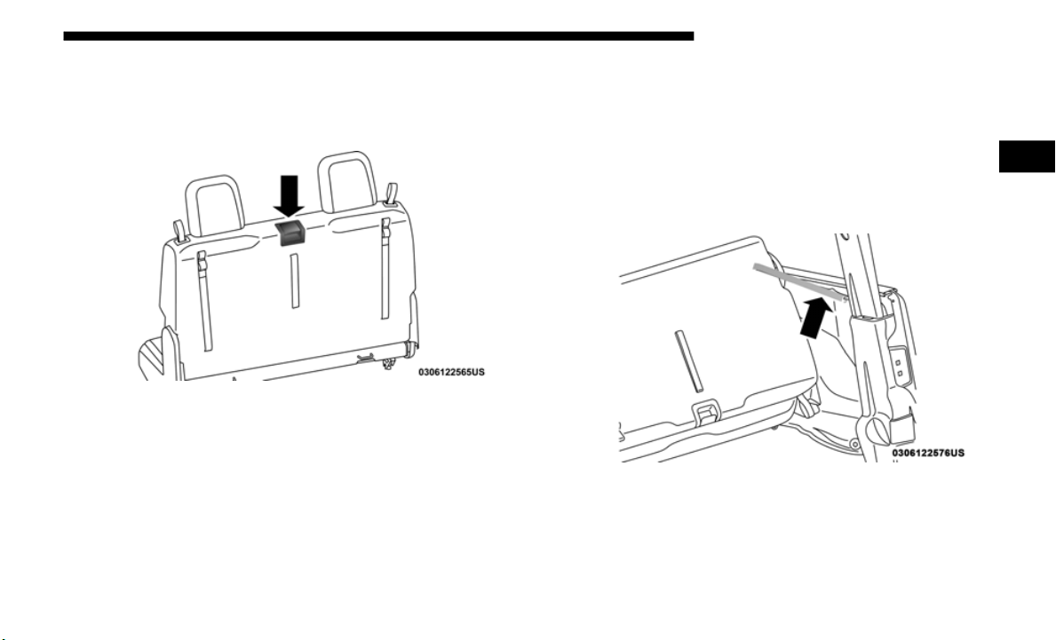
GETTING TO KNOW YOUR VEHICLE 53
Folding The Rear Seat
1. Lift the seatback release lever and fold the seatback
forward.
R
ear Seatback Release Lever
2. Slowly flip the entire seat forward.
Using Th
e Retention Straps
1. There are two retention straps located on the back of the
rear se
at and two corresponding wire loops located on
the back of each b-pillar. Open the hook-and-loop
fastener on the strap and thread through the wire loop.
Fold the hook-and-loop fastener over to keep the seat in
the folded position. This should be done on both sides.
Rear Seat Tumble Position Retention Strap
2. To return the seat to its normal upright position, reverse
these s
teps.
2
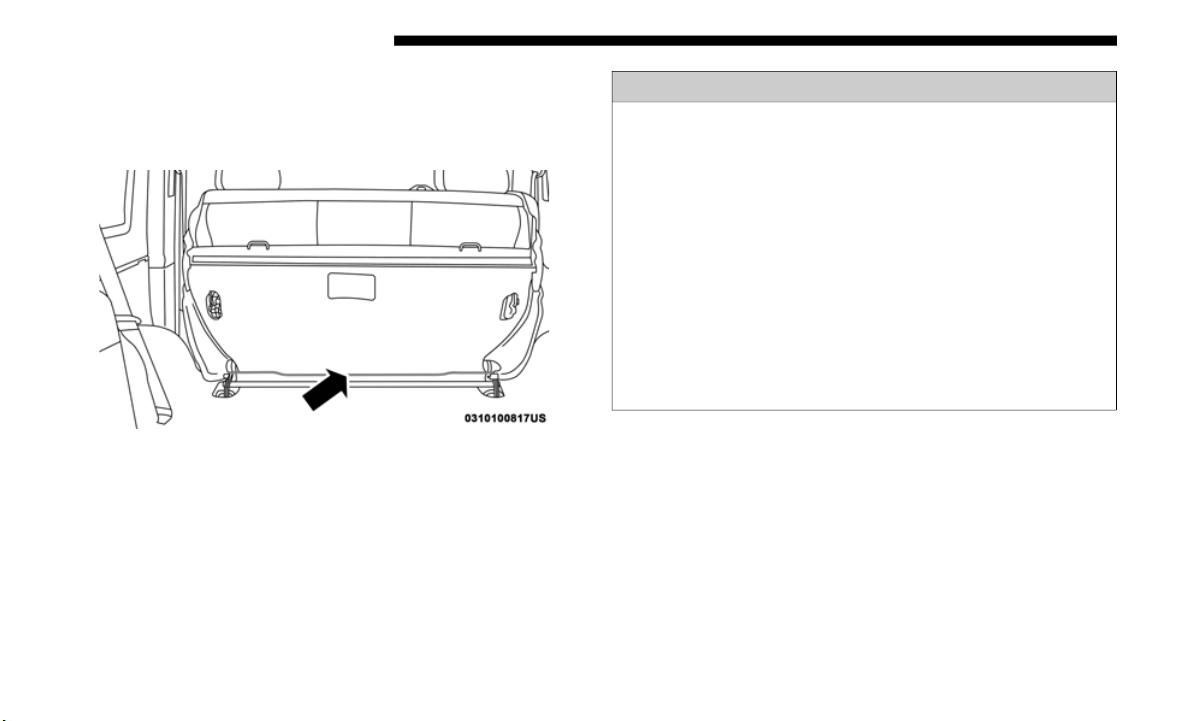
54 GETTING TO KNOW YOUR VEHICLE
Removing The Rear Seat
1. Push down on the release bar on each side, and pull the
seat ou
t and away from the lower bracket.
Release Bar Location
2. Remove the seat from the vehicle.
3. To re
install the rear seat, just reverse these steps.
NOTE:
Do
not drive the vehicle without reattaching the rear seat
l
atches.
Rear Seat Armrest — If Equipped
The center part of the rear seat can also be used as a rear
armrest with cupholders. To unfold it, grab the pull strap
under the head restraint and pull it forward.
WARNING!
• It is extremely dangerous to ride in a cargo area, inside
or outsid
e of a vehicle. In a collision, people riding in
these areas are more likely to be seriously injured or
killed.
• Do not allow people to ride in any area of your vehicle
that is
not equipped with seats and seat belts.
• Be sure everyone in your vehicle is in a seat and using
a seat
belt properly.
• In a collision, you or others in your vehicle could be
injured
if seats are not properly latched to their floor
attachments. Always be sure that the seats are fully
latched.
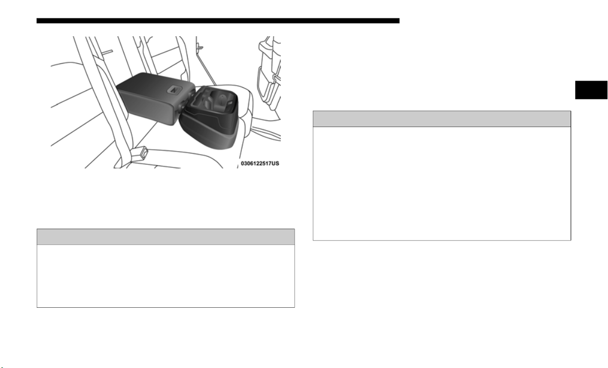
GETTING TO KNOW YOUR VEHICLE 55
Rear Seat Armrest
NOTE:
The cupholder liner can be removed for cleaning.
HEAD RESTRAINTS
Head restraints are designed to reduce the risk of injury by
restricting head movement in the event of a rear impact.
Head restraints should be adjusted so that the top of the head
restraint is located above the top of your ear.
Front Head Restraints
To raise the head restraint, pull upward on the head
restraint. To lower the head restraint, push the adjustment
button located on the base of the head restraint, and push
downward on the head restraint. The release button does not
need to be pushed to adjust the head restraint.
WARNING!
Be certain that the seatback is securely locked into
position.
If the seatback is not securely locked into
position the seat will not provide the proper stability for
child seats and/or passengers. An improperly latched
seat could cause serious injury.
WARNING!
• All occupants, including the driver, should not operate
a vehicl
e or sit in a vehicle’s seat until the head
restraints are placed in their proper positions in order
to minimize the risk of neck injury in the event of a
crash.
• Head restraints should never be adjusted while the
vehicle
is in motion. Driving a vehicle with the head
restraints improperly adjusted or removed could cause
serious injury or death in the event of a collision.
2
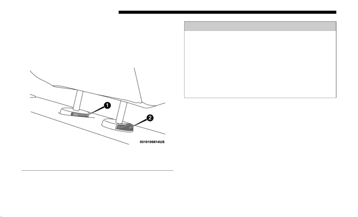
56 GETTING TO KNOW YOUR VEHICLE
To remove the head restraint, raise it as far as it can go then
push the adjustment button and the release button at the
base of each post while pulling the head restraint up. To rein
-
stall the head restraint, put the head restraint posts into the
holes an
d push downward. Then adjust it to the appropriate
height.
Front Head Restraint
NOTE:
Do not reposition the head restraint 180 degrees to the incor-
rect position in an attempt to gain additional clearance to the
back of t
he head.
1 — Release Button
2 — Adjustment Button
WARNING!
• A loose head restraint thrown forward in a collision or
hard st
op could cause serious injury or death to occu-
pants of the vehicle. Always securely stow removed
h
ead res
traints in a location outside the occupant
compartment.
• ALL the head restraints MUST be reinstalled in the
vehicle
to properly protect the occupants. Follow the
re-installation instructions above prior to operating the
vehicle or occupying a seat.
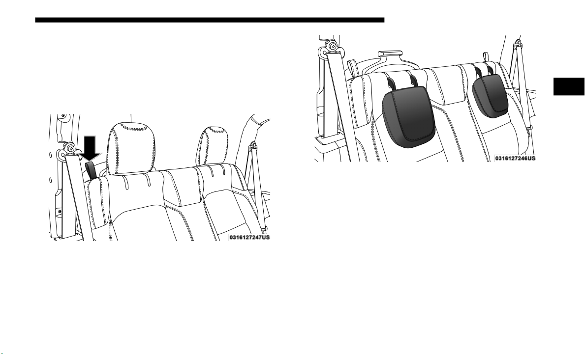
GETTING TO KNOW YOUR VEHICLE 57
Rear Head Restraints — Two Door Models
The rear seat is equipped with non-adjustable, but foldable
head restraints.
To fold the outboard head restraint, pull on the release strap
located
on the upper outboard side of each rear seat.
Rear Head Restraint Folding Strap Location
Rear Head Restraints Folded
To return the head restraint to its upward position, lift up on
the head
restraint until it locks into place.
Refer to “Occupant Restraint Systems” in “Safety” for infor-
mation on child seat tether routing.
2
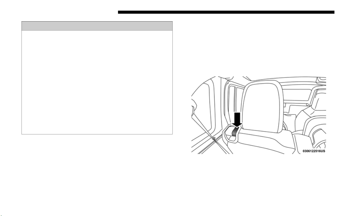
58 GETTING TO KNOW YOUR VEHICLE
Rear Head Restraints — Four Door Models
The rear seat is equipped with nonadjustable, but foldable,
outboard head restraints, as well as an adjustable, removable
center head restraint.
To fold the outboard head restraint, pull on the inner release
lever, l
ocated on the upper part of the rear seat.
Rear Head Restraint Lever
WARNING!
• Do not drive the vehicle without the rear seat head
restrai
nts installed while passengers are occupying the
rear seat. In a collision, people riding in this area
without the head restraints installed are more likely to
be seriously injured or killed.
• A loose head restraint thrown forward in a collision or
hard st
op could cause serious injury or death to occu-
pants of the vehicle. Always securely stow removed head
r
estrain
ts in a location outside the occupant compart-
ment.
• A
LL the head restraints MUST be reinstalled in the
vehicle
to properly protect the occupants. Follow the
reinstallation instructions above prior to operating the
vehicle or occupying a seat.
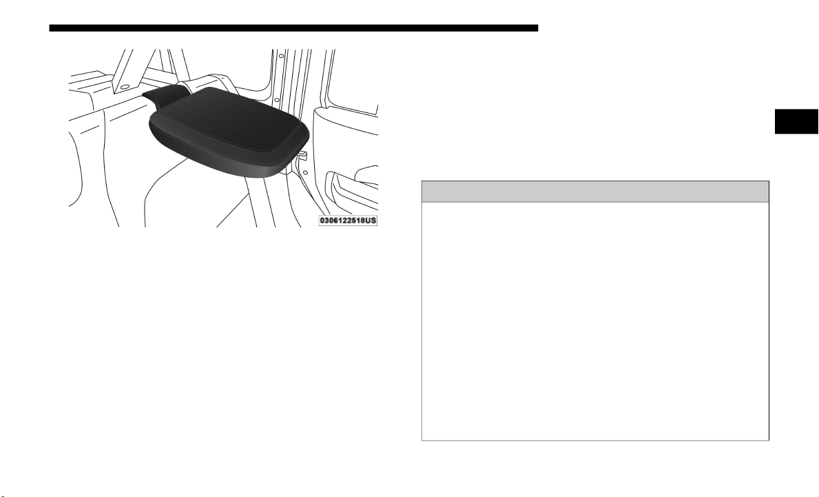
GETTING TO KNOW YOUR VEHICLE 59
Rear Head Restraint Folded
To return the head restraint to its upward position, lift up on
the head
restraint until it locks into place.
To raise the center head restraint, lift up on the head
restrain
t. To lower the center head restraint, push the adjust-
ment button, located at the base of the head restraint, and
p
ush down
on the head restraint.
To remove the center head restraint, push the release button,
located
on the base of the head restraint, and pull upward on
the head restraint.
To install the head restraint, hold the release button while
pushing d
ownward on the head restraint. Refer to “Occu-
pant Restraint Systems” in “Safety” for information on child
s
eat tet
her routing.
NOTE:
Lower the center head restraint to avoid contact with the
c
enter c
onsole when folding the seat down.
WARNING!
• Do not drive the vehicle without the rear seat head
restrai
nts installed while passengers are occupying the
rear seat. In a collision, people riding in this area
without the head restraints installed are more likely to
be seriously injured or killed.
• A loose head restraint thrown forward in a collision or
hard st
op could cause serious injury or death to occu-
pants of the vehicle. Always securely stow removed
h
ead res
traints in a location outside the occupant
compartment.
• ALL the head restraints MUST be reinstalled in the
vehicle
to properly protect the occupants. Follow the
reinstallation instructions above prior to operating the
vehicle or occupying a seat.
2
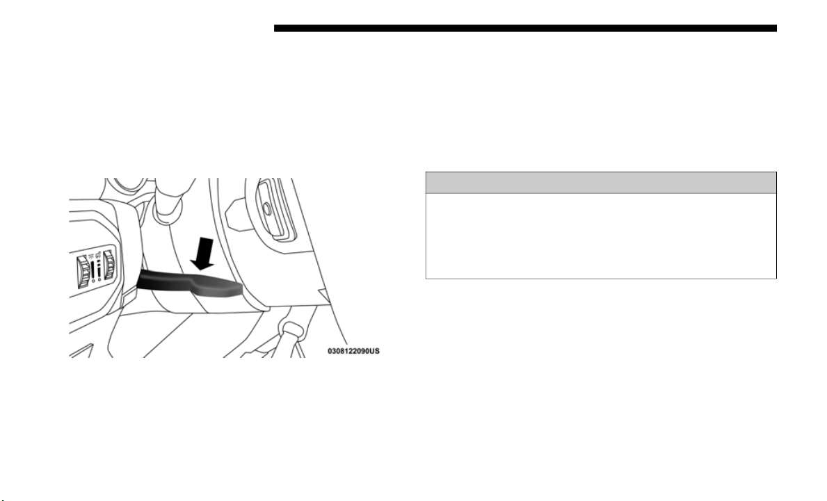
60 GETTING TO KNOW YOUR VEHICLE
STEERING WHEEL
Tilt/Telescoping Steering Column
This feature allows you to tilt the steering column upward or
downward. It also allows you to lengthen or shorten the
steering column. The tilt/telescoping lever is located on the
steering column, below the turn signal lever.
Tilt/Telescoping Steering Column Lever
To unlock the steering column, push the control handle
downward (
toward the floor). To tilt the steering column,
move the steering wheel upward or downward as desired.
To lengthen or shorten the steering column, pull the steering
wheel outward or push it inward as desired. To lock the
steering column in position, push the control handle upward
until fully engaged.
WARNING!
Do not adjust the steering column while driving.
Adjustin
g the steering column while driving or driving
with the steering column unlocked, could cause the
driver to lose control of the vehicle. Failure to follow this
warning may result in serious injury or death.

GETTING TO KNOW YOUR VEHICLE 61
Heated Steering Wheel — If Equipped
The steering wheel contains a heating element that helps
warm your hands in cold weather. The heated steering wheel
has only one temperature setting. Once the heated steering
wheel has been turned on, it will stay on until the operator
turns it off. The heated steering wheel may not turn on when
it is already warm.
The heated steering wheel control button is located on the
center
of the instrument panel below the touchscreen and
within the climate or controls screen of the touchscreen.
• Push the heated steering wheel button once
to turn the
heating element on.
• Push the heated steering wheel button a sec
ond time to
turn the heating element off.
NOTE:
The engine must be running for the heated steering wheel to
o
perate
.
Vehicles Equipped With Remote Start
On models that are equipped with remote start, the heated
steerin
g wheel can be programmed to come on during a
remote start.
This feature can be programmed through the Uconnect
system.
Refer to “Uconnect Settings” in “Multimedia” for
further information.
WARNING!
• Persons who are unable to feel pain to the skin because
of advan
ced age, chronic illness, diabetes, spinal cord
injury, medication, alcohol use, exhaustion, or other
physical conditions must exercise care when using the
steering wheel heater. It may cause burns even at low
temperatures, especially if used for long periods.
• Do not place anything on the steering wheel that insu-
lates
against heat, such as a blanket or steering wheel
covers of
any type and material. This may cause the
steering wheel heater to overheat.
2
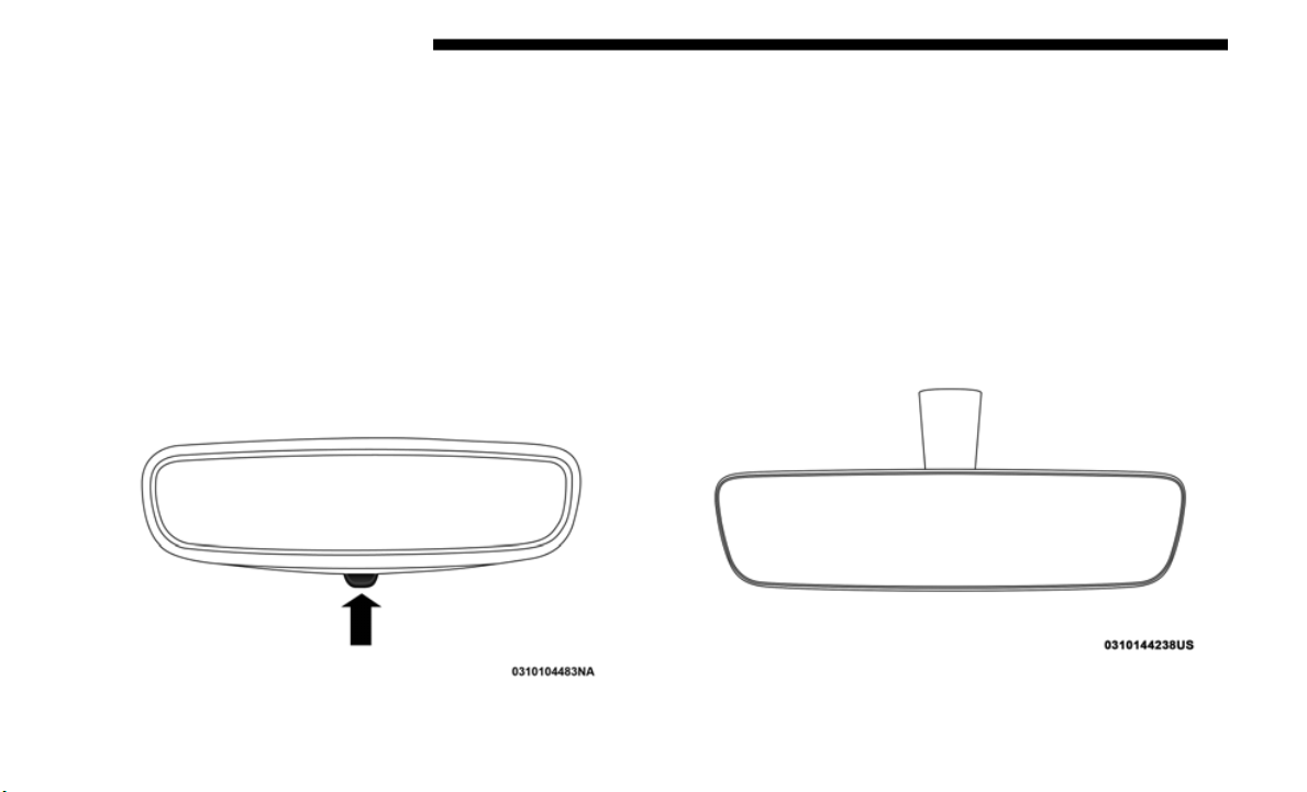
62 GETTING TO KNOW YOUR VEHICLE
MIRRORS
Inside Day/Night Mirror — If Equipped
The mirror head can be adjusted up, down, left, and right for
various drivers. The mirror should be adjusted to center on
the view through the rear window.
Headlight glare from vehicles behind you can be reduced by
moving th
e small control under the mirror to the night posi-
tion (toward the rear of the vehicle). The mirror should be
a
djusted
while set in the day position (toward the wind-
shield).
Adjusting Rearview Mirror
Automatic Dimming Mirror — If Equipped
The mirror head can be adjusted up, down, left, and right for
various drivers. The mirror should be adjusted to center on
the view through the rear window.
The mirror automatically adjusts to headlight glare from
vehicles
behind you.
NOTE:
The Automatic Dimming feature is disabled when the
v
ehicle
is in REVERSE to improve the driver’s view.
Automatic Dimming Mirror
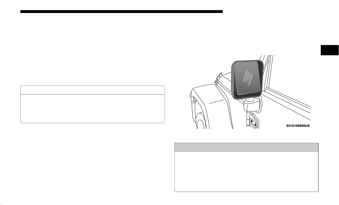
GETTING TO KNOW YOUR VEHICLE 63
The Automatic Dimming feature can be turn on or off
through the touchscreen.
• Press the mirror dimmer button once to turn the feature
on.
• Pres
s the mirror dimmer button a second time to turn the
feature
off.
Refer to “Uconnect Settings” in “Multimedia” for further
informat
ion.
Outside Mirrors
To receive maximum benefit, adjust the outside mirror(s) to
center on the adjacent lane of traffic with a slight overlap of
the view obtained on the inside mirror.
Outside Rearview Mirror
CAUTION!
To avoid damage to the mirror during cleaning, never
spray any
cleaning solution directly onto the mirror.
Apply the solution onto a clean cloth and wipe the
mirror clean.
WARNING!
Vehicles and other objects seen in the passenger side
convex m
irror will look smaller and farther away than they
really are. Relying too much on your passenger side mirror
could cause you to collide with another vehicle or other
object. Use your inside mirror when judging the size or
distance of a vehicle seen in the passenger side mirror.
2
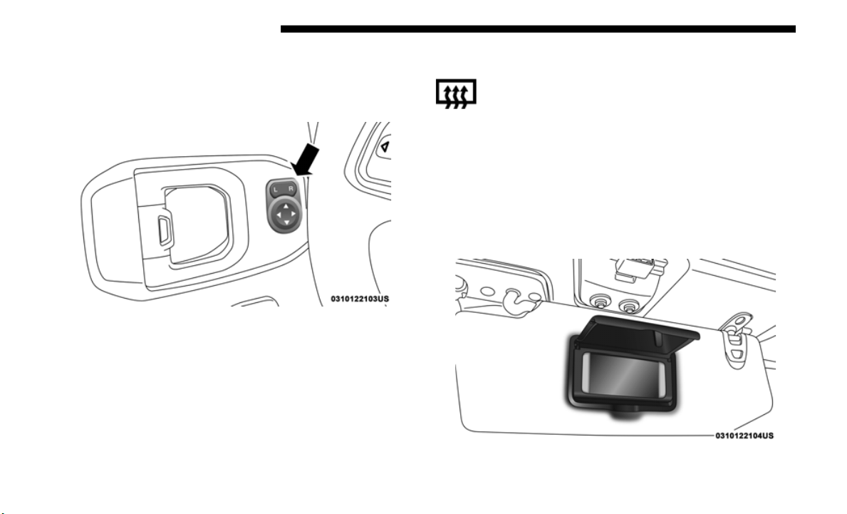
64 GETTING TO KNOW YOUR VEHICLE
Power Mirrors — If Equipped
The power mirror controls are located on the door panel next
to the door handle.
Power Mirror Switch
The power mirror controls consist of mirror select buttons
and a fo
ur-way mirror control switch. To adjust a mirror,
push either the L (left) or R (right) button to select the mirror
that you want to adjust.
Using the mirror control switch, push any of the four arrows
for the
direction that you want the mirror to move.
Heated Mirrors — If Equipped
These mirrors are heated to melt frost or ice. This
feature will be activated whenever you turn on the
rear wind
ow defroster (if equipped). Refer to
“Climate Controls” in “Getting To Know Your Vehicle” for
further information.
Vanity Mirrors
Vanity mirrors are located on the sun visors. To use the
mirrors, rotate the sun visor down and swing the mirror
cover upward.
Vanity Mirror
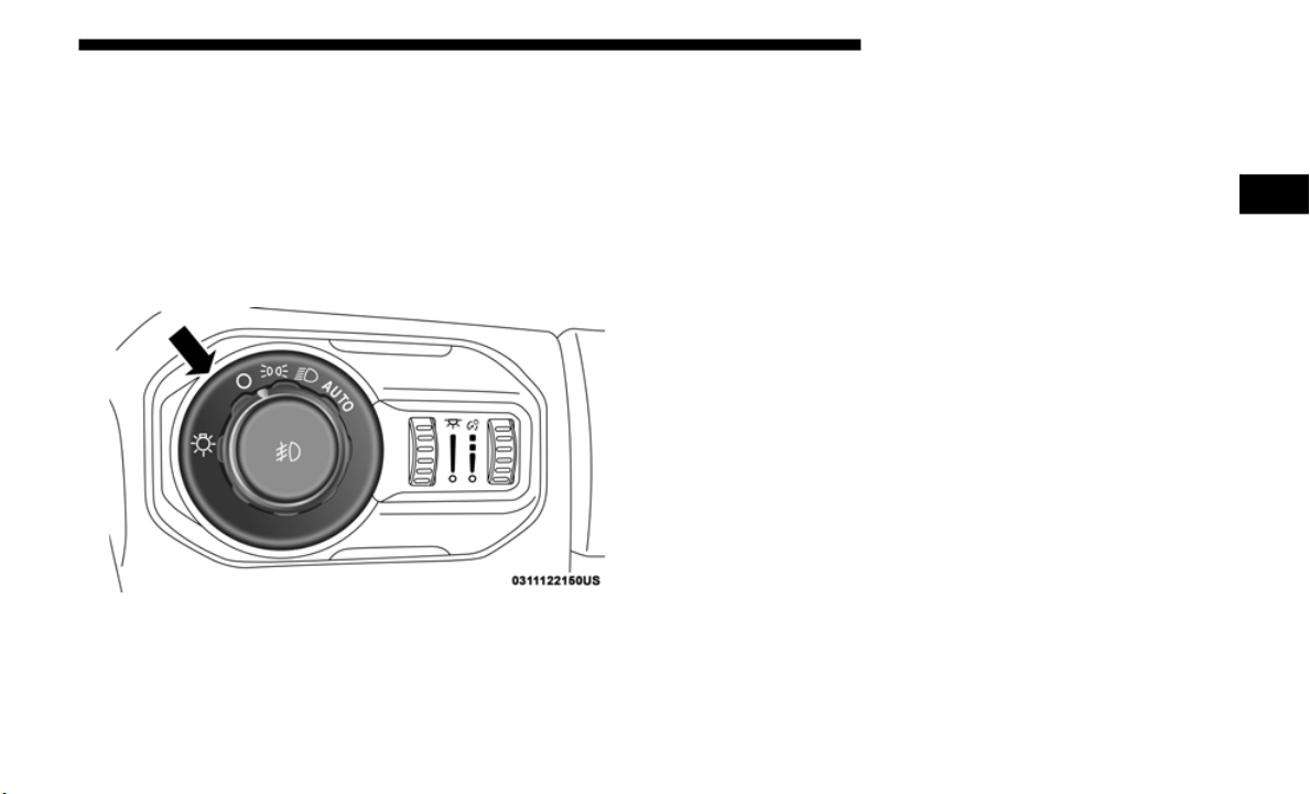
GETTING TO KNOW YOUR VEHICLE 65
EXTERIOR LIGHTS
Headlight Switch
The headlight switch is located on the left side of the instru-
ment panel. This switch controls the operation of the head-
lights, parking lights, automatic headlights — if equipped,
i
nstrume
nt panel lights, instrument panel light dimming,
interior lights, and fog lights — if equipped.
Headlight Switch
Rotate the headlight switch clockwise to the first detent for
p
arking li
ght and instrument panel light operation. Rotate
the headlight switch to the second detent for headlight,
parking light, and instrument panel light operation.
Daytime Running Lights — If Equipped
The Daytime Running Lights (DRLs) are in a dedicated posi-
tion below the headlight assembly. DRLs are active when the
Low Beams
are not and when the vehicle is shifted into any
position other than PARK (auto transmission), or when the
vehicle begins to move (manual transmission).
NOTE:
The Daytime Running Lights, on the same side of the vehicle
a
s the a
ctive turn signal, will turn off automatically when a
turn signal is in operation and turn on again when the turn
signal is not operating.
2
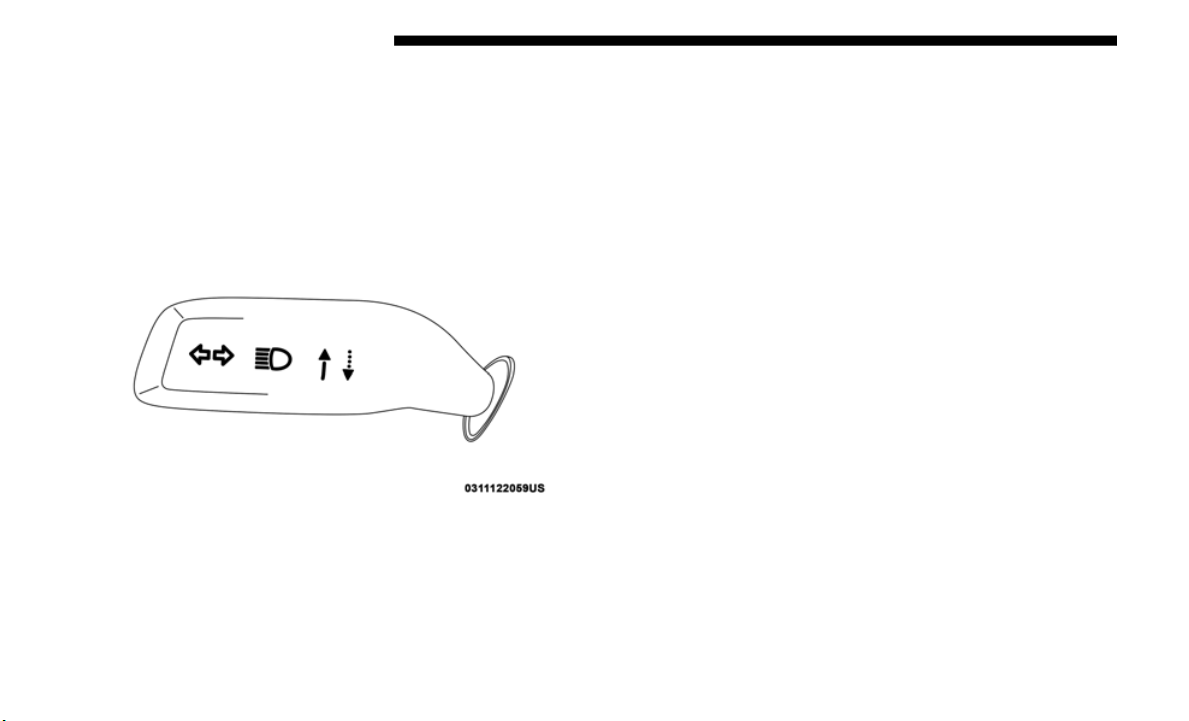
66 GETTING TO KNOW YOUR VEHICLE
High/Low Beam Switch
Push the multifunction lever toward the instrument panel to
switch the headlights to high beams. The lever will return to
the centered position. To return the headlights to low beam,
pull the lever toward the steering wheel, or push the lever
toward the instrument panel.
Multifunction Lever
Flash-To-Pass
You can signal another vehicle with your headlights by
lightly pulling the multifunction lever toward you. This will
cause the high beam headlights to turn on, and remain on,
until the lever is released.
Automatic Headlights — If Equipped
This system automatically turns the headlights on or off
according to ambient light levels. To turn the system on,
rotate the headlight switch clockwise to the last detent for
automatic headlight operation. When the system is on, the
headlight time delay feature is also on. This means the head
-
lights will stay on for up to 90 seconds after you place the
ignition
into the OFF position. To turn the automatic system
off, move the headlight switch out of the AUTO position.
NOTE:
The engine must be running before the headlights will come
on in th
e automatic mode.
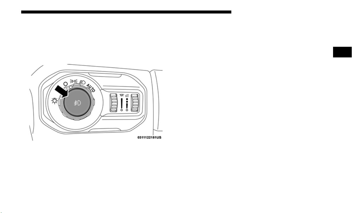
GETTING TO KNOW YOUR VEHICLE 67
Front Fog Lights — If Equipped
To activate the front fog lights, turn on the parking lights or
low beam headlights and push in the center of the headlight
switch control knob. Pushing the headlight switch control
knob a second time will turn the front fog lights off.
Front Fog Light Switch
Turn Signals
Move the multifunction lever up or down and the arrows on
each side of the instrument cluster flash to show proper oper-
ation of the front and rear turn signal lights.
NOTE:
If either light remains on and does not flash, or there is a very
f
ast fla
sh rate, check for a defective outside light bulb. If an
indicator fails to light when the lever is moved, it would
suggest that the indicator bulb is defective.
Lane Change Assist — If Equipped
Tap the multifunction lever up or down once, without
moving beyond the detent, and the turn signal (right or left)
will flash three times then automatically turn off.
Lights-On Reminder
If the headlights, parking lights, or cargo lights are left on
after the ignition is turned OFF, a chime will sound when the
driver’s door is opened.
2
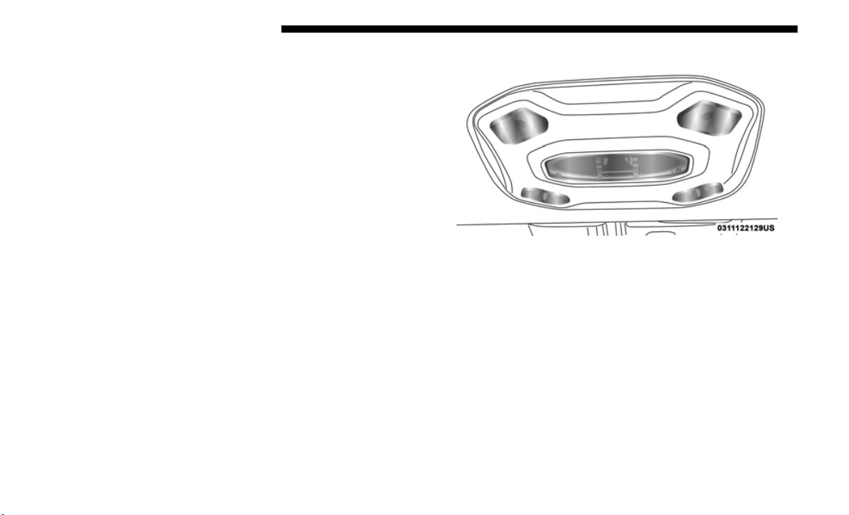
68 GETTING TO KNOW YOUR VEHICLE
INTERIOR LIGHTS
Courtesy Lights
The courtesy lights will turn on when the front doors are
opened, by rotating the dimmer controls on the headlight
switch fully upward, or, if equipped, when the unlock
button is pushed on the key fob.
The interior courtesy lights are located in the center of the
vehicle’s
sport bar, and consist of one large center light and
four smaller reading lights. Each reading light can be turned
on by pushing the lens. Pushing the lens a second time will
turn the light off.
Dome Lights
When a door is open and the interior lights are on, rotating
the dimm
er control to the extreme bottom position will cause
all the interior lights to turn off. This is also known as “Party”
mode because it allows the doors to stay open for extended
periods of time without discharging the vehicle’s battery.
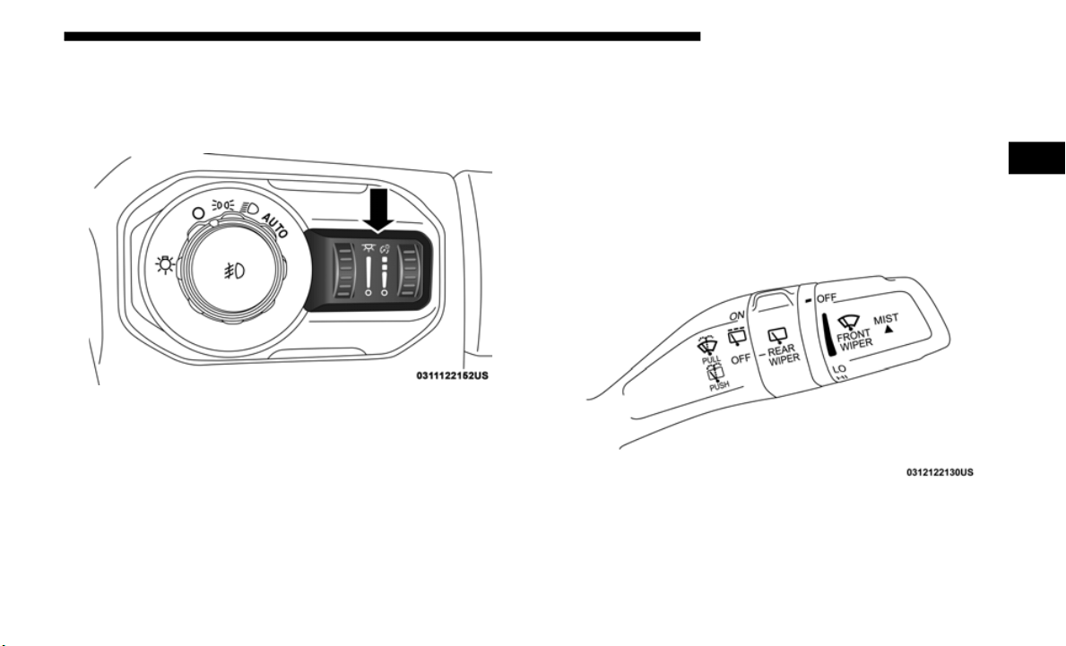
GETTING TO KNOW YOUR VEHICLE 69
Dimmer Controls
The dimmer controls are part of the headlight switch and are
located on the left side of the instrument panel.
Dimmer Controls
With the parking lights or headlights on, rotating the right
dimmer c
ontrol upward will increase the brightness of the
instrument panel lights. Rotating the left dimmer control will
adjust the interior and ambient light levels.
WINDSHIELD WIPERS AND WASHERS
The windshield wiper/washer control lever is located on the
right side of the steering column. The front wipers are oper-
ated by rotating a switch, located at the end of the lever.
Refer to “Rear Window Wiper/Washer” in this section for
f
urther
information on using the rear window wiper/
washer.
Windshield Wiper/Washer Lever
2
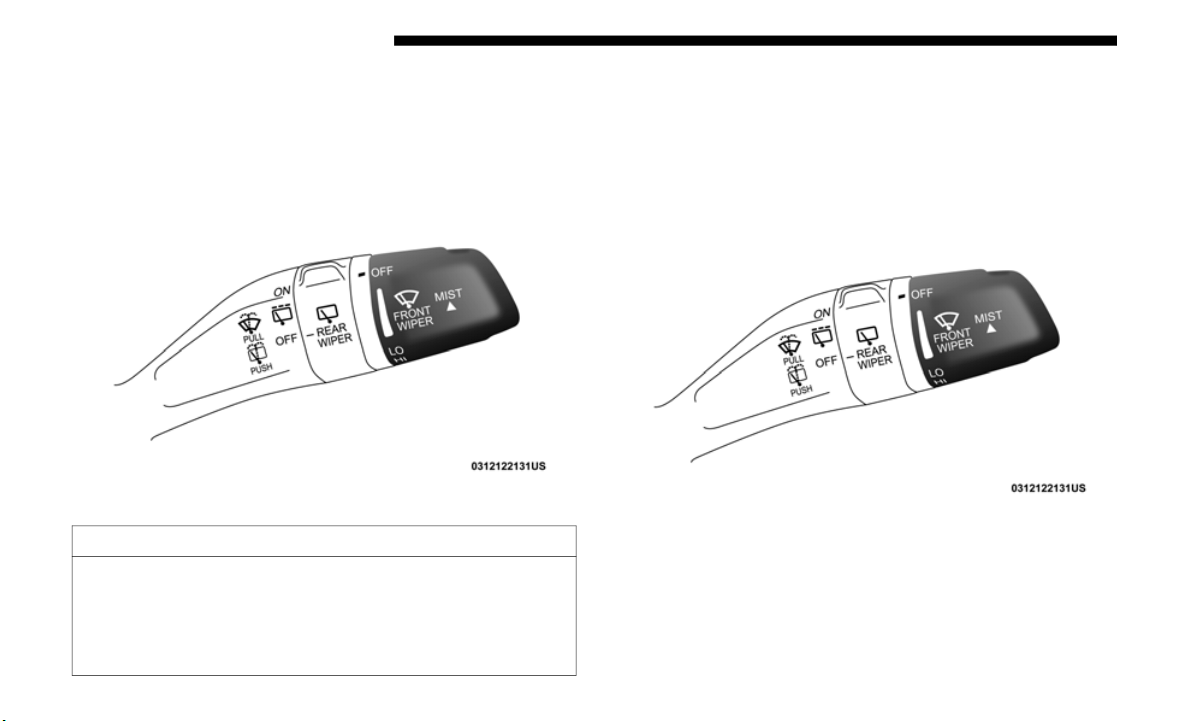
70 GETTING TO KNOW YOUR VEHICLE
Windshield Wiper Operation
Rotate the end of the lever upward to the second detent past
the intermittent settings for low-speed wiper operation.
Rotate the end of the lever upward to the third detent past
the intermittent settings for high-speed wiper operation.
Front Wiper Control
Intermittent Wiper System
Use the intermittent wiper when weather conditions make a
s
ingle wip
ing cycle, with a variable pause between cycles,
desirable. Rotate the end of the lever to the first detent posi
-
tion for one of four intermittent settings. The delay cycle can
be set a
nywhere between 1 to 18 seconds.
Front Wiper Control
NOTE:
The wiper delay times depend on vehicle speed. If the
v
ehicle
is moving less than 10 mph (16 km/h), delay times
will be d
oubled.
CAUTION!
In cold weather, always turn off the wiper switch and
allow the
wipers to return to the park position before
turning off the engine. If the wiper switch is left on and
the wipers freeze to the windshield, damage to the wiper
motor may occur when the vehicle is restarted.

GETTING TO KNOW YOUR VEHICLE 71
Windshield Washers
To use the washer, pull the lever toward you and hold while
spray is
desired. If the lever is pulled while in the delay
range, the wiper will start and continue to operate for two or
three wipe cycles after the lever is released. Then, the inter
-
mittent interval previously selected will resume.
If the lever is pulled while in the off position, the wipers will
o
perate
for two or three wipe cycles. Then, the wipers will
turn off.
Mist Feature
Push upward on the wiper lever to activate a single wipe to
clear of
f road mist or spray from a passing vehicle. As long
as the lever is held up, the wipers will continue to operate.
NOTE:
The mist feature does not activate the washer pump; there-
fore, no washer fluid will be sprayed on the windshield. The
wa
sh func
tion must be used in order to spray the windshield
with washer fluid.
Mist Control
WARNING!
Sudden loss of visibility through the windshield could
lead to a
collision. You might not see other vehicles or
other obstacles. To avoid sudden icing of the windshield
during freezing weather, warm the windshield with the
defroster before and during windshield washer use.
2
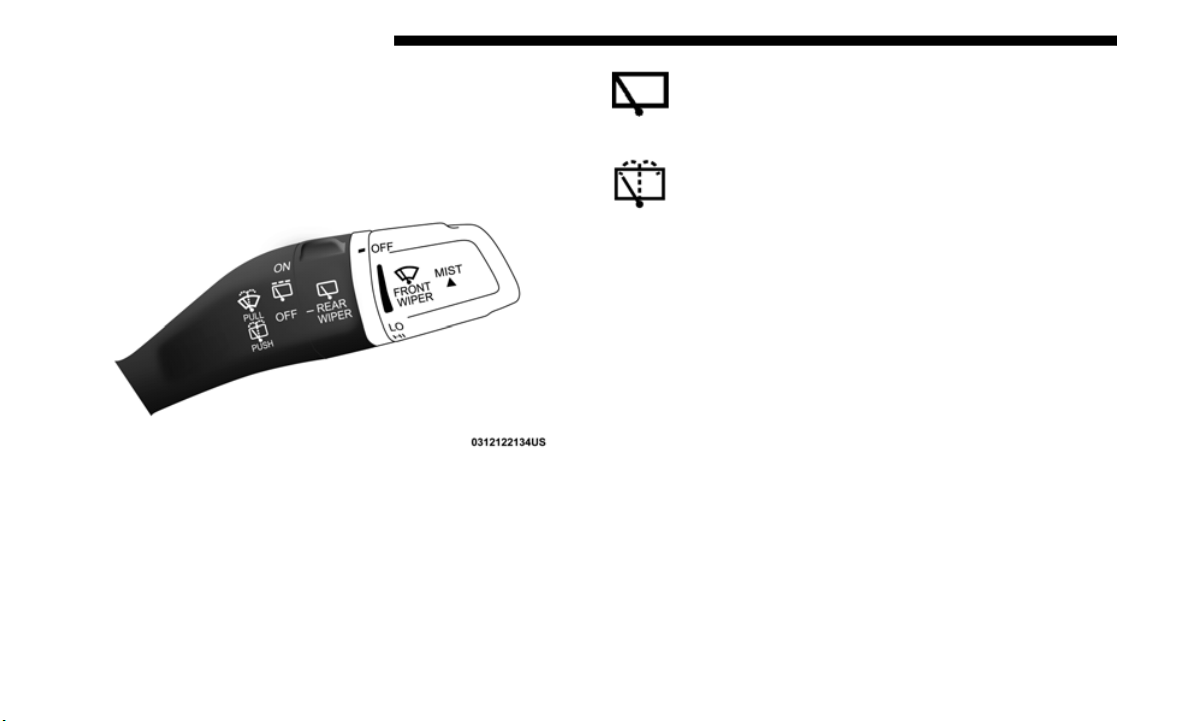
72 GETTING TO KNOW YOUR VEHICLE
Rear Window Wiper/Washer — If Equipped
A rotary switch on the center portion of the windshield
wiper/washe
r lever controls the operation of the rear
wiper/washer function.
Rear Wiper/Washer Control
Rotate the switch upward to the first detent position
for intermittent operation and to the second detent
for cont
inuous rear wiper operation.
Push the wiper lever toward the instrument panel to
activate the rear washer. The washer pump and wiper
w
ill con
tinue to operate as long as the lever is held.
If the rear wiper is operating when the ignition is placed in
the OFF po
sition, the wiper will automatically return to the
“park” position. When the vehicle is restarted, the wiper will
resume function at whichever position the switch is set at.
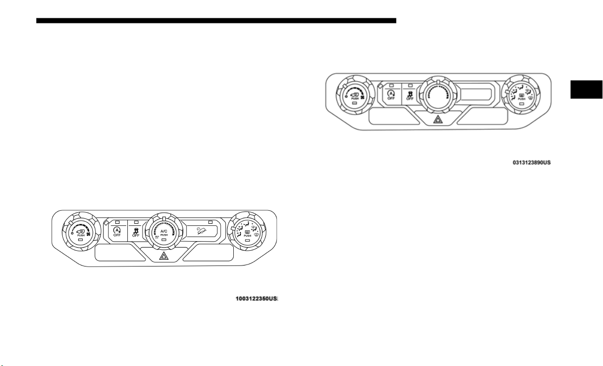
GETTING TO KNOW YOUR VEHICLE 73
CLIMATE CONTROLS
The Climate Control System allows you to regulate the
temperature, air flow, and direction of air circulating
throughout the vehicle. The controls are located on the
touchscreen (if equipped) and on the instrument panel
below the radio.
Manual Climate Control Overview
The air conditioning and heating system is designed to make
you comfortable in all types of weather.
Manual Climate Controls
Manual Climate Controls – Heater Only
2
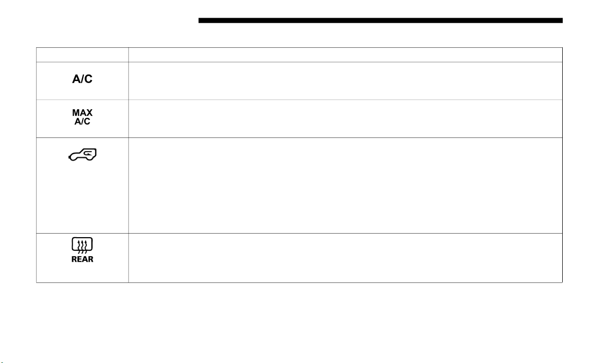
74 GETTING TO KNOW YOUR VEHICLE
Manual Climate Control Descriptions
Icon Description
A/C Button — If Equipped
Push the A/C button to engage the Air Conditioning (A/C). An LED illuminates when the A/C
system is
engaged.
MAX A/C Setting — If Equipped
Turn the temperature control knob to the MAX Air Conditioning (A/C) setting to engage MAX Air
C
onditio
ning (A/C). This is the coldest setting.
Recirculation Button
Press and release this button on the touchscreen, or push the button on the faceplate, to change the
s
ystem be
tween recirculation mode and outside air mode. Recirculation can be used when outside
conditions such as smoke, odors, dust, or high humidity are present. Recirculation can be used in all
modes except for Defrost. Recirculation may be unavailable if conditions exist that could create
fogging on the inside of the windshield.
The A/C can be deselected manually without disturbing the
mode con
trol selection. Continuous use of the Recirculation mode may make the inside air stuffy and
window fogging may occur. Extended use of this mode is not recommended.
Rear Defrost Button
Push and release the Rear Defrost Control button to turn on the rear window defroster and the heated
outside
mirrors (if equipped). An indicator will illuminate when the rear window defroster is on. The
rear window defroster automatically turns off after ten minutes.
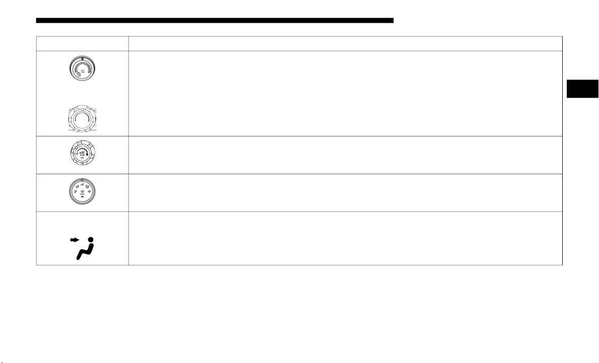
GETTING TO KNOW YOUR VEHICLE 75
Heater Only
Temperature Control
Use this control to regulate the temperature of the air inside the passenger compartment. Rotating the
knob coun
terclockwise, from top center into the blue area of the scale, indicates cooler temperatures.
Rotating the knob clockwise, into the red area, indicates warmer temperatures.
Heater Only
Rotating clockwise increases the heating temperature and rotating counter clockwise decreases
h
eating t
emperature.
Blower Control
Use this control to regulate the amount of air forced through the system in any mode you select. The
b
lower sp
eed increases as you move the control clockwise from the off position.
Modes Control
Turn the knob to adjust airflow distribution. The airflow distribution mode can be adjusted so air
c
omes fr
om the instrument panel outlets, floor outlets, defrost outlets and demist outlets.
Panel Mode
Panel Mode
Air comes from the outlets in the instrument panel. Each of these outlets can be individually adjusted
t
o direc
t the flow of air. The air vanes of the center outlets and outboard outlets can be moved up and
down or side to side to regulate airflow direction.
Icon Description
2

76 GETTING TO KNOW YOUR VEHICLE
Bi-Level Mode
Bi-Level Mode
Air comes from the instrument panel outlets and floor outlets. A slight amount of air is directed
t
hrough t
he defrost and side window demister outlets.
NOTE:
Bi-Level mode is designed under comfort conditions to provide cooler air out of the panel outlets and
wa
rmer ai
r from the floor outlets.
Floor Mode
Floor Mode
Air comes from the floor outlets. A slight amount of air is directed through the defrost and side
wi
ndow dem
ister outlets.
Mix Mode
Mix Mode
Air is directed through the floor, defrost, and side window demister outlets. This setting works best in
c
old or
snowy conditions that require extra heat to the windshield. This setting is good for
maintaining comfort while reducing moisture on the windshield.
Front Defrost Mode
Turn the Knob to the Front Defrost position. Air comes from the windshield and side window demist
outlets.
Use Defrost mode with maximum temperature settings for best windshield and side window
defrosting and defogging.
Icon Description
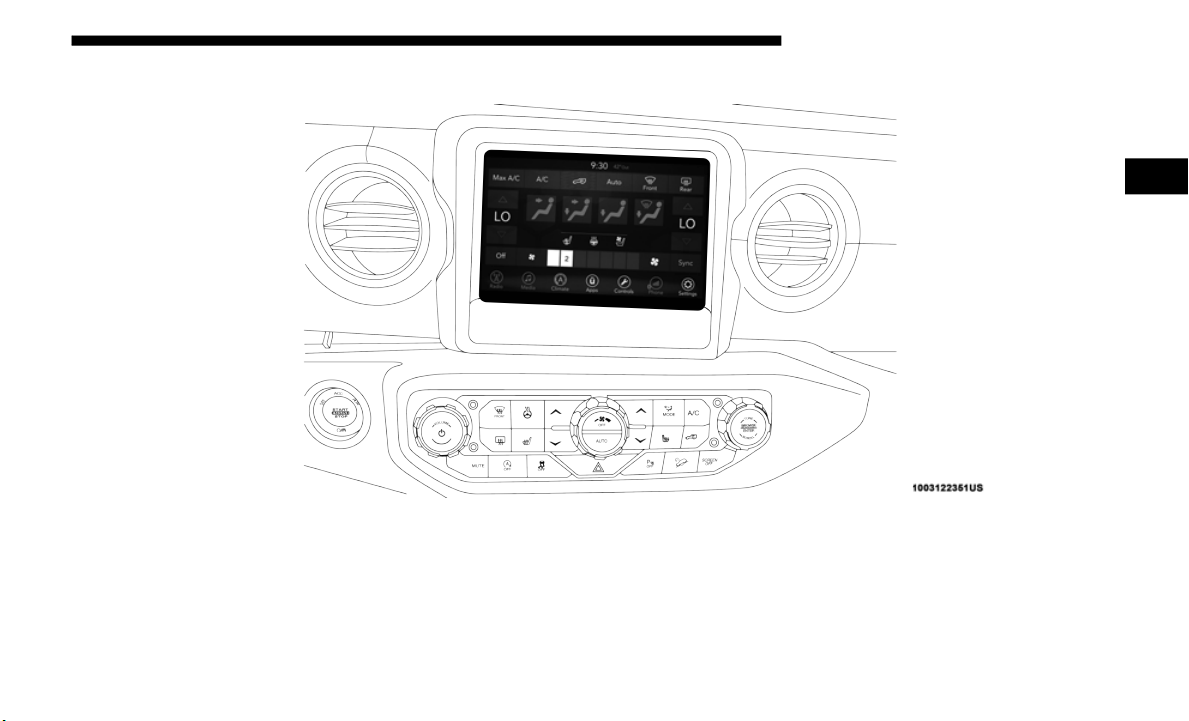
GETTING TO KNOW YOUR VEHICLE 77
Automatic Climate Controls Overview
Uconnect 4 With 7–inch Display Automatic Climate Controls
2
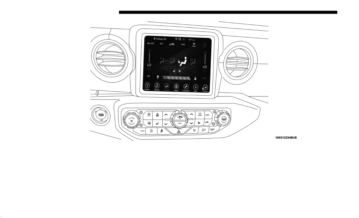
78 GETTING TO KNOW YOUR VEHICLE
Uconnect 4C/4C NAV With 8.4–inch Display Automatic Climate Controls
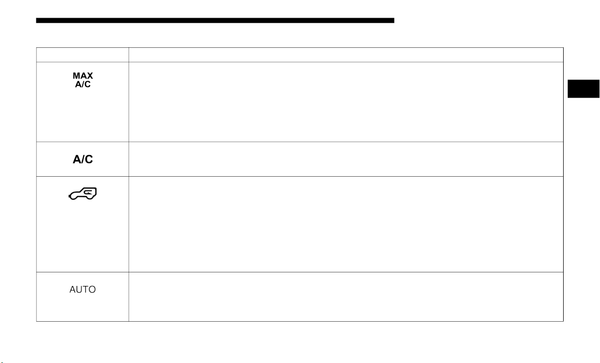
GETTING TO KNOW YOUR VEHICLE 79
Automatic Control Descriptions
Icon Description
MAX A/C Button
Press to change to the coldest setting, the indicator illuminates when MAX A/C is on. Pressing the
button a
gain causes the MAX A/C operation to switch into manual mode and the MAX A/C
indicator turns off.
NOTE:
The MAX A/C button is only available on the touchscreen.
A/C Button
Press and release to change the current setting. The indicator illuminates when A/C is on.
Recirculation Button
Press and release this button on the touchscreen, or push the button on the faceplate, to change the
s
ystem be
tween recirculation mode and outside air mode. Recirculation can be used when outside
conditions, such as smoke, odors, dust, or high humidity are present. Recirculation can be used in all
modes. Recirculation may be unavailable (button on the touchscreen greyed out) if conditions exist
that could create fogging on the inside of the windshield. The A/C can be deselected manually
without disturbing the mode control selection. Continuous use of the Recirculation mode may make
the inside air stuffy and window fogging may occur. Extended use of this mode is not recommended.
AUTO Button
Automatically controls the interior cabin temperature by adjusting airflow distribution and amount.
Toggling th
is button causes the system to switch between manual mode and automatic modes.
Refer to “Automatic Operation” within this section for more information.
2
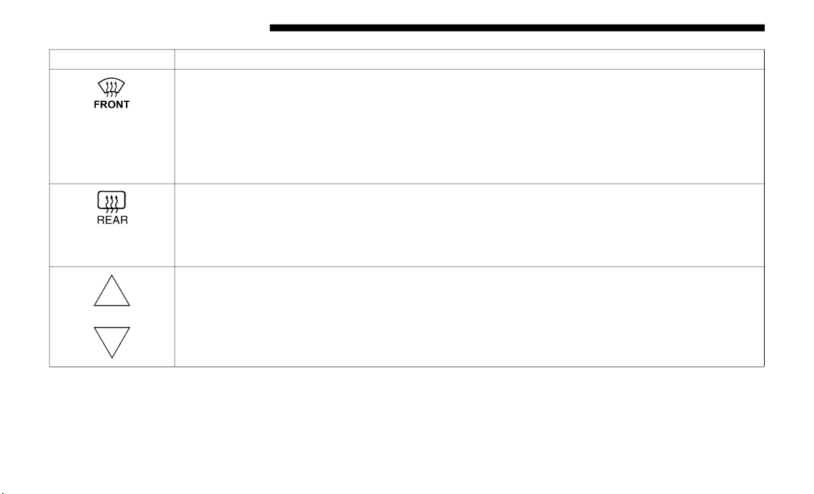
80 GETTING TO KNOW YOUR VEHICLE
Front Defrost Button
Press and release the touchscreen button, or push and release the button on the faceplate, to change
the curr
ent airflow setting to Defrost mode. The indicator illuminates when this feature is on. Air
comes from the windshield and side window demist outlets. When the defrost button is selected, the
blower level may increase. Use Defrost mode with maximum temperature settings for best
windshield and side window defrosting and defogging. When toggling the front defrost mode
button, the climate system returns to the previous setting.
Rear Defrost Button
Press and release the button on the touchscreen, or push and release the button on the faceplate, to
t
urn on
the rear window defroster and the heated outside mirrors (if equipped). An indicator
illuminates when the rear window defroster is on. The rear window defroster automatically turns off
after ten minutes.
Driver And Passenger Temperature Up And Down Buttons
Provides the driver and passenger with independent temperature control. Push the red button on the
f
aceplat
e or touchscreen or press and slide the temperature bar towards the red arrow button on the
touchscreen for warmer temperature settings. Push the blue button on the faceplate or touchscreen or
press and slide the temperature bar towards the blue arrow button on the touchscreen for cooler
temperature settings.
Icon Description
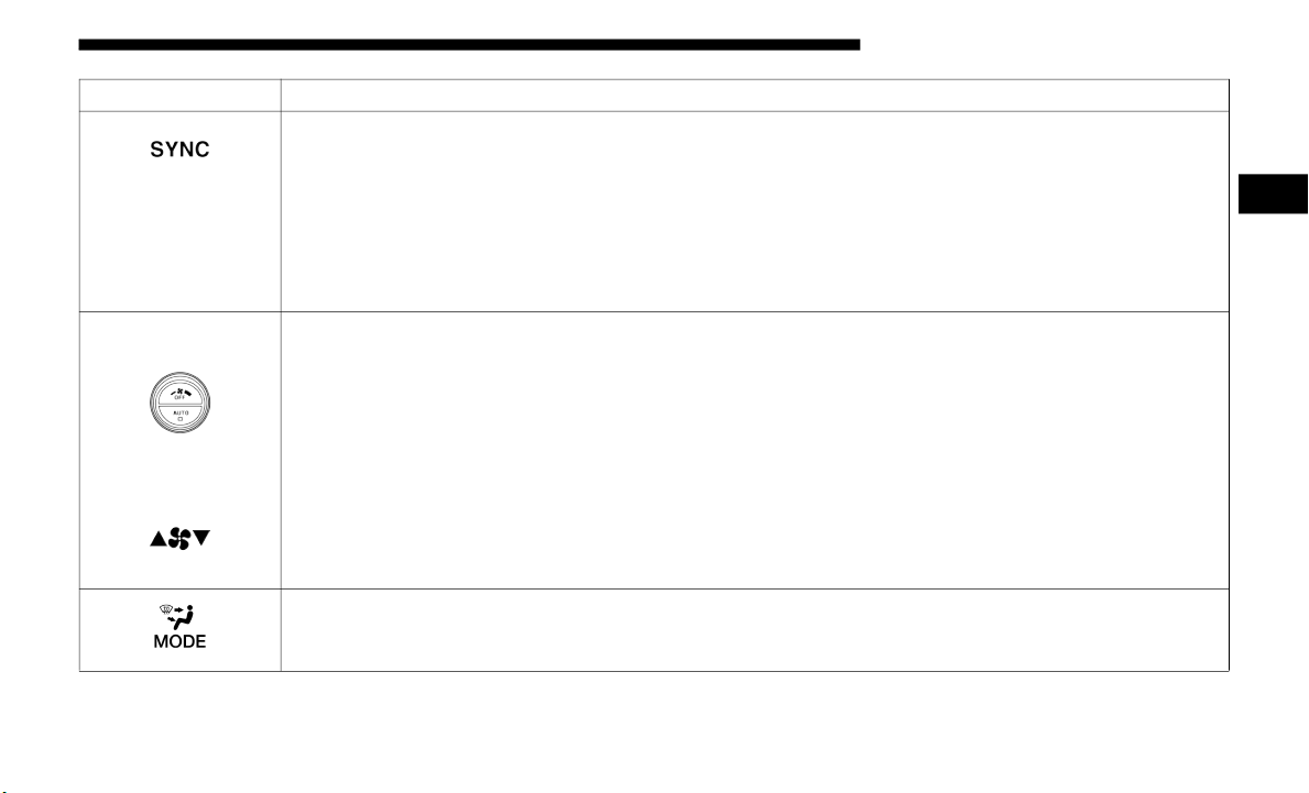
GETTING TO KNOW YOUR VEHICLE 81
SYNC Button
Press the SYNC button on the touchscreen to toggle the SYNC feature on/off. The SYNC indicator is
illumina
ted when this feature is enabled. SYNC is used to synchronize the passenger temperature
setting with the driver temperature setting. Changing the passenger’s temperature setting while in
SYNC will automatically exit this feature.
NOTE:
The SYNC button is only available on the touchscreen.
Faceplate Knob
Touchscreen
B
uttons
Blow
er Control
Blower Control is used to regulate the amount of air forced through the climate system. There are
s
even bl
ower speeds available. The speeds can be selected using either the blower control knob on the
faceplate or the buttons on the touchscreen.
• Faceplate: The bl
ower speed increases as you turn the blower control knob clockwise from the
lowest blower setting. The blower speed decreases as you turn the blower control knob counter-
clockwise.
• T
ouchscreen: Use th
e small blower icon to reduce the blower setting and the large blower icon to
increase the blower setting. The blower can also be selected by pressing the blower bar area between
the icons.
Modes Control
Press the button to adjust airflow distribution. The airflow distribution mode can be adjusted so air
comes fr
om the instrument panel outlets, floor outlets, defrost outlets and demist outlets.
Icon Description
2

82 GETTING TO KNOW YOUR VEHICLE
Panel Mode
Panel Mode
Air comes from the outlets in the instrument panel. Each of these outlets can be individually adjusted
t
o direc
t the flow of air. The air vanes of the center outlets and outboard outlets can be moved up and
down or side to side to regulate airflow direction. There is a shut off wheel located below the air
vanes to shut off or adjust the amount of airflow from these outlets.
Bi-Level Mode
Bi-Level Mode
Air comes from the instrument panel outlets and floor outlets. A slight amount of air is directed
t
hrough t
he defrost and side window demister outlets.
NOTE:
Bi-Level mode is designed under comfort conditions to provide cooler air out of the panel outlets and
wa
rmer ai
r from the floor outlets.
Floor Mode
Floor Mode
Air comes from the floor outlets. A slight amount of air is directed through the defrost and side
wi
ndow dem
ister outlets.
Mix Mode
Mix Mode
Air is directed through the floor, defrost, and side window demister outlets. This setting works best in
c
old or
snowy conditions that require extra heat to the windshield. This setting is good for
maintaining comfort while reducing moisture on the windshield.
Climate Control OFF Button
This button turns the Climate Control System off.
Icon Description

GETTING TO KNOW YOUR VEHICLE 83
Climate Control Functions
A/C (Air Conditioning)
The Air Conditioning (A/C) button allows the operator to
manuall
y activate or deactivate the air conditioning system.
When the air conditioning system is turned on, cool dehu
-
midified air will flow through the outlets into the cabin. For
improve
d fuel economy, press the A/C button to turn off the
air conditioning and manually adjust the blower and airflow
mode settings. Also, make sure to select only Panel, Bi-Level,
or Floor modes.
NOTE:
• For Manual Climate Controls, if the system is in Mix, Floor
or Def
rost Mode, the A/C can be turned off, but the A/C
system shall remain active to prevent fogging of the
windows.
• If fog or mist appears on the windshield or side glass,
select
Defrost mode, and increase blower speed if needed.
• If your air conditioning performance seems lower than
expect
ed, check the front of the A/C condenser (located in
front of the radiator), for an accumulation of dirt or insects.
Clean with a gentle water spray from the front of the radi
-
ator and through the condenser.
MAX A/C
MAX A/C sets the control for maximum cooling perfor-
mance.
Press and release to toggle between MAX A/C and the prior
s
ettings
. The button illuminates when MAX A/C is on.
In MAX A/C, the blower level and mode position can be
adjuste
d to desired user settings. Pressing other settings will
cause the MAX A/C operation to switch to the selected
setting and MAX A/C to exit.
Recirculation
In cold weather, use of Recirculation mode may lead to
excessi
ve window fogging. The Recirculation feature may be
unavailable (button on the touchscreen greyed out) if condi
-
tions exist that could create fogging on the inside of the
windshie
ld.
On systems with Manual Climate Controls, if equipped, the
Recircu
lation mode is not allowed in Defrost mode to
improve window clearing operation. Recirculation is
disabled automatically if this mode is selected. Attempting
to use Recirculation while in this mode causes the LED in the
control button to blink and then turns off.
2

84 GETTING TO KNOW YOUR VEHICLE
Automatic Temperature Control (ATC) — If Equipped
Automatic Operation
1. Push the AUTO button on the faceplate, or the AUTO
button
on the touchscreen on the Automatic Temperature
Control (ATC) Panel.
2. Next, adjust the temperature that you would like the
system
to maintain by adjusting the driver and passenger
temperature control buttons. Once the desired tempera-
ture is displayed, the system will achieve and automati-
cally maintain that comfort level.
3. When the system is set up for your comfort level, it is not
necess
ary to change the settings. You will experience the
greatest efficiency by simply allowing the system to func-
tion automatically.
NOTE:
• I
t is not necessary to move the temperature settings for
cold o
r hot vehicles. The system automatically adjusts the
temperature, mode, and blower speed to provide comfort
as quickly as possible.
• The temperature can be displayed in U.S. or Metric units
by sele
cting the US/Metric customer-programmable
feature. Refer to the “Uconnect Settings” in “Multimedia”
for further information.
To provide you with maximum comfort in the Automatic
mode du
ring cold start-ups, the blower fan will remain on
low until the engine warms up. The blower will increase in
speed and transition into Auto mode.
Manual Operation Override
This system offers a full complement of manual override
feature
s. The AUTO symbol in the front ATC display will be
turned off when the system is being used in the manual
mode.
Operating Tips
NOTE:
Refer to the chart at the end of this section for suggested
control
settings for various weather conditions.
Summer Operation
The engine cooling system must be protected with a
h
i
gh-qua
lity antifreeze coolant to provide proper corrosion
protection and to protect against engine overheating. OAT
coolant (conforming to MS.90032) is recommended.

GETTING TO KNOW YOUR VEHICLE 85
Winter Operation
To ensure the best possible heater and defroster perfor-
mance, make sure the engine cooling system is functioning
properl
y and the proper amount, type, and concentration of
coolant is used. Use of the Air Recirculation mode during
Winter months is not recommended, because it may cause
window fogging.
Vacation/Storage
Before you store your vehicle, or keep it out of service (i.e.,
vacatio
n) for two weeks or more, run the air conditioning
system at idle for about five minutes, in fresh air with the
blower setting on high. This will ensure adequate system
lubrication to minimize the possibility of compressor
damage when the system is started again.
Window Fogging
Vehicle windows tend to fog on the inside in mild, rainy,
and/or h
umid weather. To clear the windows, select Defrost
or Mix mode and increase the front blower speed. Do not use
the Recirculation mode without A/C for long periods, as
fogging may occur.
Outside Air Intake
Make sure the air intake, located directly in front of the wind-
shield, is free of obstructions, such as leaves. Leaves collected
in the
air intake may reduce airflow, and if they enter the
plenum, they could plug the water drains. In Winter months,
make sure the air intake is clear of ice, slush, and snow.
CAUTION!
Failure to follow these cautions can cause damage to the
heating
elements:
• Use care when washing the inside of the rear window.
Do not u
se abrasive window cleaners on the interior
surface of the window. Use a soft cloth and a mild
washing solution, wiping parallel to the heating
elements. Labels can be peeled off after soaking with
warm water.
• Do not use scrapers, sharp instruments, or abrasive
window
cleaners on the interior surface of the window.
• Keep all objects a safe distance from the window.
2
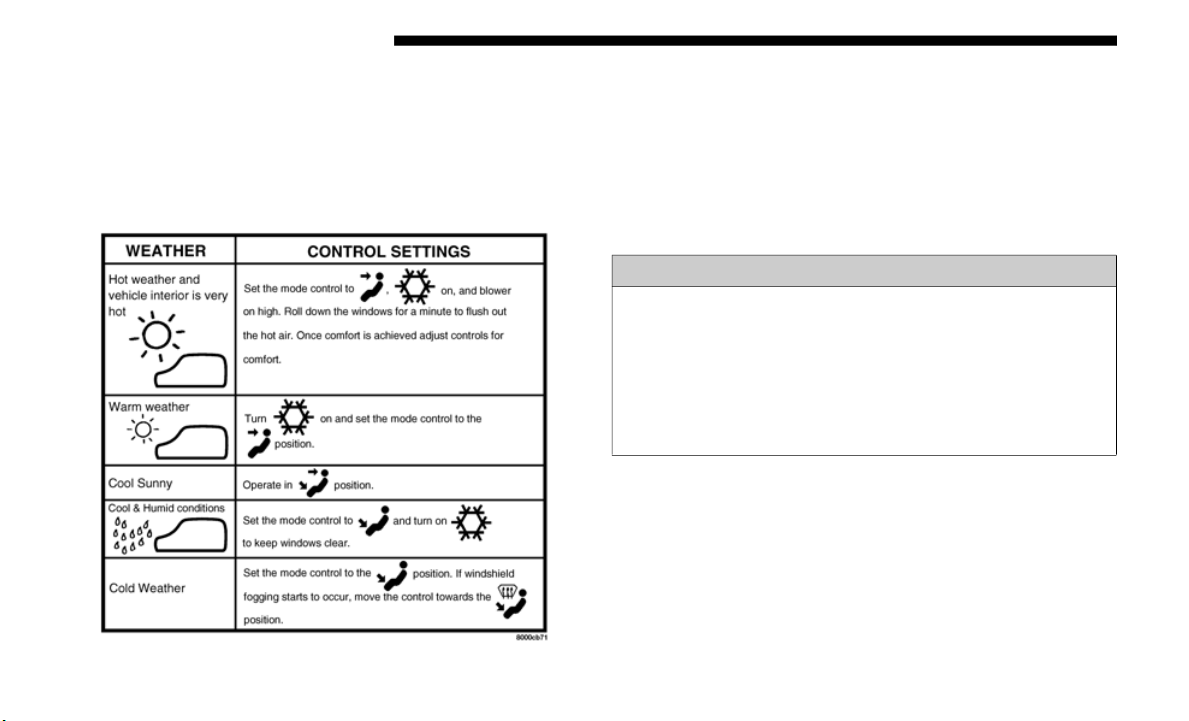
86 GETTING TO KNOW YOUR VEHICLE
Cabin Air Filter
The climate control system filters out dust and pollen from
the air
. Contact an authorized dealer to service your cabin air
filter, and to have it replaced when needed.
Operating Tips Chart
POWER WINDOWS — IF EQUIPPED
The power window switches are located on the instrument
panel below the climate controls. Push the switch downward
to open the window and upward to close the window.
The top left switch controls the left front window and the top
right swi
tch controls the right front window.
WARNING!
Never leave children unattended in a vehicle, and do not
let chi
ldren play with power windows. Do not leave the
key fob in or near the vehicle, or in a location accessible
to children. Occupants, particularly unattended children,
can become entrapped by the windows while operating
the power window switches. Such entrapment may
result in serious injury or death.
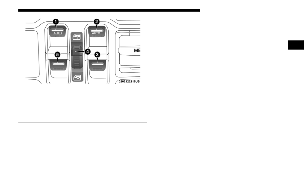
GETTING TO KNOW YOUR VEHICLE 87
Power Window Switches
NOTE:
The power window switches will remain active for up to
10 minute
s after ignition is switched to the OFF position.
Opening e
ither front door will cancel this feature.
Four-Door Models
The lower left switch controls the left rear passenger
window, an
d the lower right switch controls the right rear
passenger window.
NOTE:
There are window switches located on the rear of the center
console
for the rear passenger windows in the four-door
model.
Auto-Down Feature
The driver door power window switch and the passenger
door power window switches have an Auto-Down feature.
Push the window switch down, for a short period of time,
and release and the window will go down automatically.
To open the window part way, push the window switch
down brie
fly and release it when you want the window to
stop.
To stop the window from going all the way down during the
Auto-Down
operation, pull up on the switch briefly.
1 — Driver Side Front Window Switch
2 — Passenger Side Front Window Switch
3 — Passenger Side Rear Window Switch
4 — Window Lockout Switch
5 — Driver Side Rear Window Switch
2
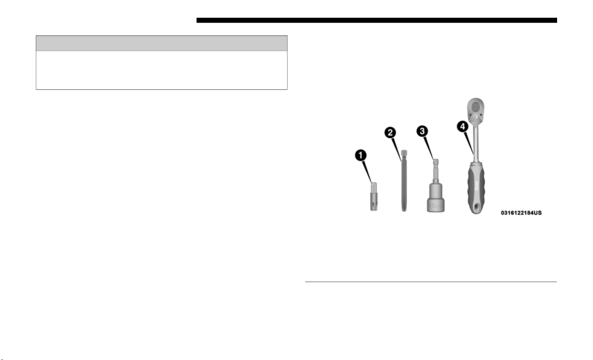
88 GETTING TO KNOW YOUR VEHICLE
Wind Buffeting
Wind buffeting can be described as the perception of pres-
sure on the ears or a helicopter-type sound in the ears. Your
vehicle
may exhibit wind buffeting with the windows down
in certain open or partially open positions. This is a normal
occurrence and can be minimized by adjusting the window
opening.
DUAL TOP FOUR DOOR MODELS — IF EQUIPPED
If your vehicle is equipped with a Dual Top, the soft top
system will be provided in a separate box located in the rear
of the vehicle for shipping purposes only. The soft top and
the hard top are to be used independently. Your vehicle
warranty will not cover damage resulting from both tops
being installed at the same time.
For your convenience, a tool kit is provided with your
vehicle
located in the center console. This kit includes the
necessary tools required for the operations described in the
following sections. All pieces fit into the ratchet for easy use.
Provided Tools
WARNING!
There is no anti-pinch protection when the window is
almost cl
osed. Be sure to clear all objects from the
window before closing.
1 — #50 Torx Head Driver
2 — #40 Torx Head Driver
3 — 15mm Socket
4 — Ratchet
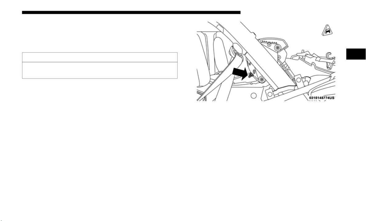
GETTING TO KNOW YOUR VEHICLE 89
Removing The Soft Top — Four Door Models
1. Fully lower the soft top. Refer to “Soft Top — Four Door
Models” in this section.
2. Make sure the lift assist mechanism on both the left and
right si
des are in the “lock” position, and an audible
“click” is heard when pushing down on the #1 bow from
each of the lift assist mechanisms before removing.
Lock Position
CAUTION!
Failure to follow the next steps could result in damage to
the Soft
Top or vehicle.
2
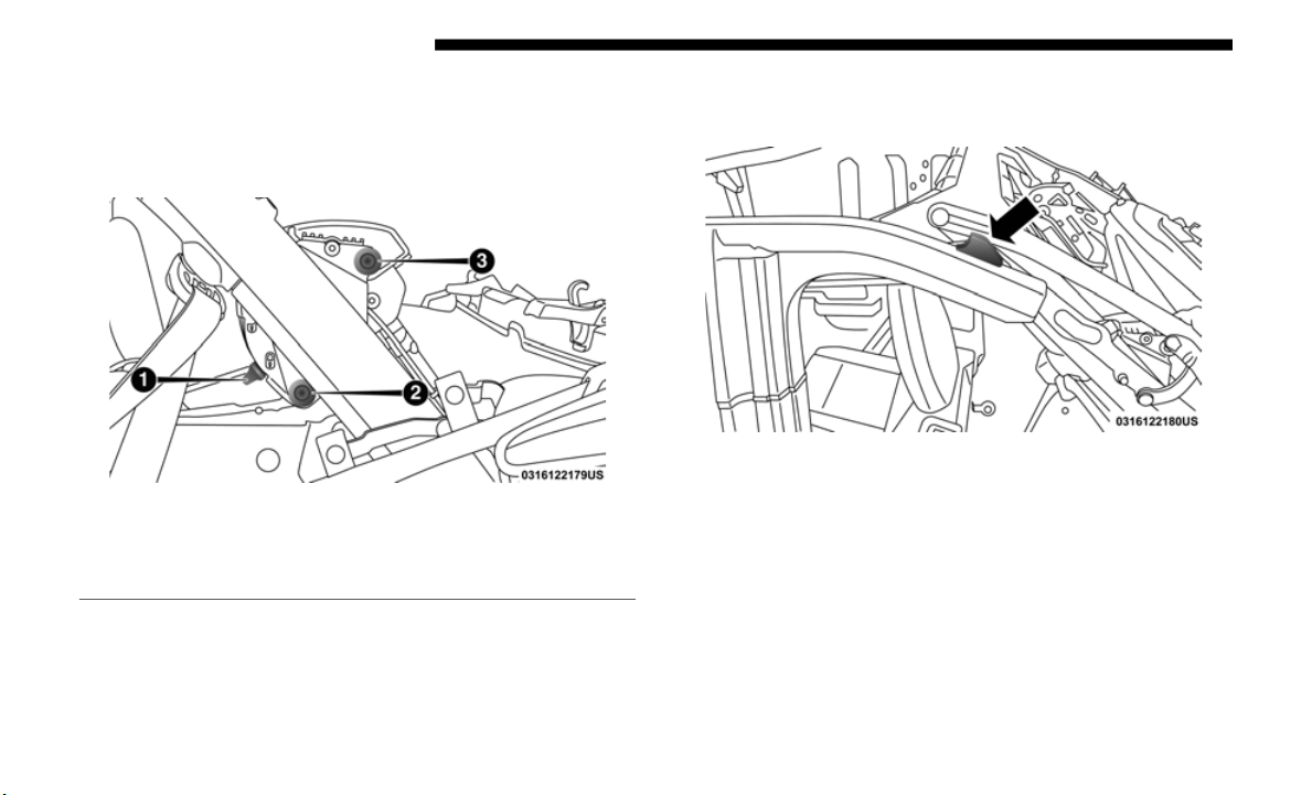
90 GETTING TO KNOW YOUR VEHICLE
3. Using the provided #40 Torx head driver and ratchet,
unscrew the two Torx head screws on each lift assist
mechanism, then lift the mechanism up and away from
the vehicle.
Lift Assist Mechanism
4. Pull the release lever on top of the rail rearward to release
the side link from the track.
Release Lever Location
1 — Lock Position
2 — Torx Head Screw
3 — Torx Head Screw
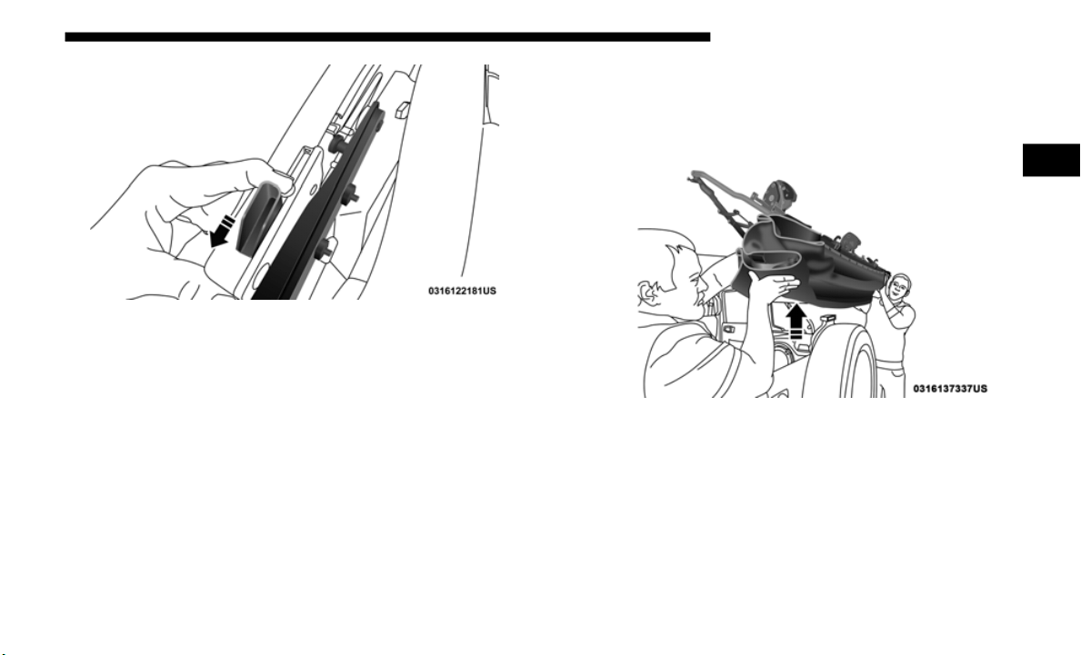
GETTING TO KNOW YOUR VEHICLE 91
Pull To Release Top From Track
5. Repeat on the opposite side.
6. Utili
zing two people, lift the soft top up and away from
the veh
icle, careful to avoid the vehicle’s sport bar, trim,
and tire carrier. Store the soft top in a safe, clean, and dry
location.
Utilize Two People To Remove Soft Top
2
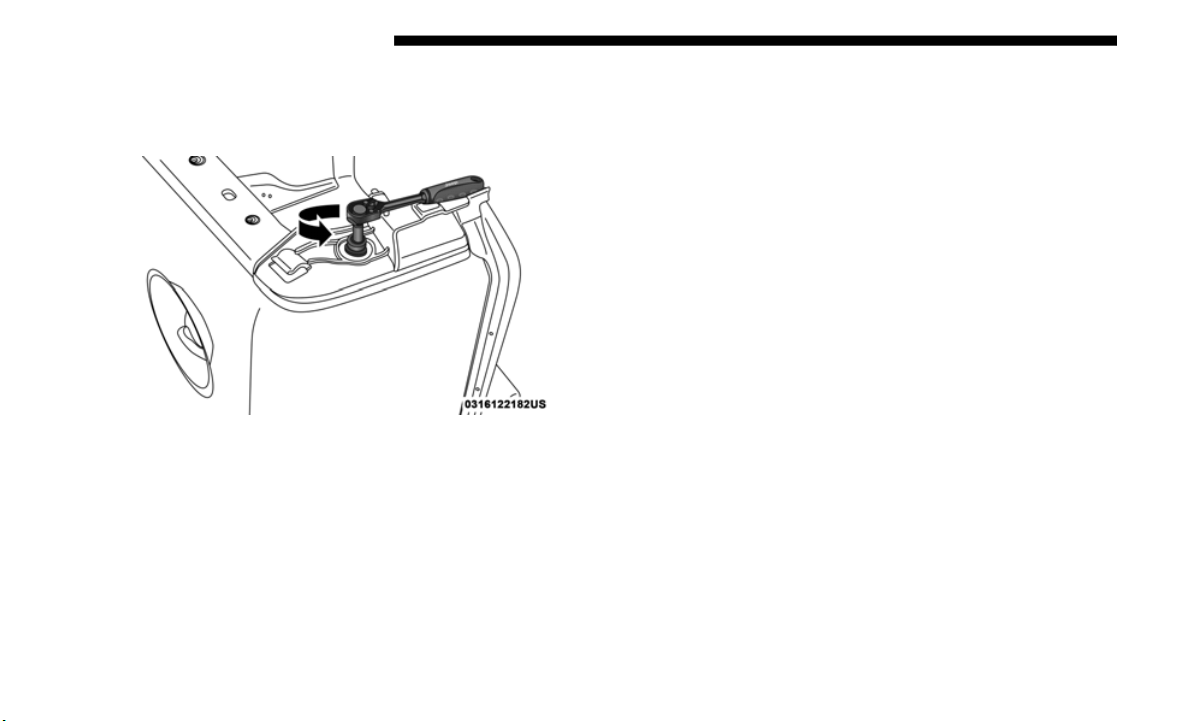
92 GETTING TO KNOW YOUR VEHICLE
7. Using the provided #50 Torx head driver and ratchet,
unscrew the Torx screw on both rear corners of the
vehicle, removing the retainers.
Remove Rear Retainers
Installing The Soft Top — Four Door Models
NOTE:
The following procedures are for first time set up only. For
future s
oft top procedures, refer to “Soft Top” in this section.
1. Locate and remove the following items prior to hard top
removal
:
• Right and left side door rails
• Eight d
oor frame attachment Torx head screws
• Right a
nd left side quarter windows
• Rear wi
ndow
• Swing gat
e bar
2. Remov
e the hard top. Refer to “Rear Hard Top Removal”
in this
section.
3. Install the door rails, starting with the front, followed by the
rear on
each side. Refer to “Door Frame Installation — Four
Door Models” in this section for instructions and appro
-
priate torque specifications for the door rail Torx screws.
4. I
nstall the rear retainers on each side of the rear of the
vehicle
using the provided #50 Torx head driver and
ratchet.
Refer to the table below for recommended torque
specifications.
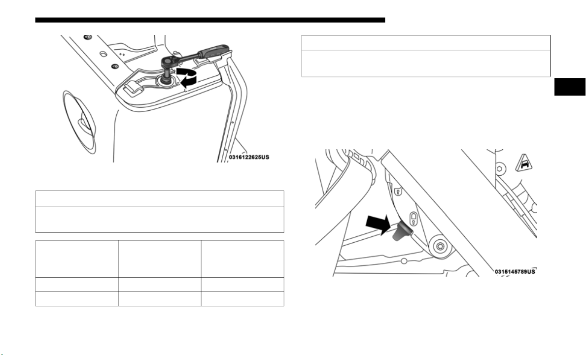
GETTING TO KNOW YOUR VEHICLE 93
Installing Rear Retainers
5. Making sure the lift assist mechanism is in the “lock”
positio
n, lift the soft top into the rear of the vehicle with
the side links pointing toward the front. Lower the lift
assist mechanisms onto its retainers on both sides (on the
inside of the sport bar).
Lock Position
CAUTION!
Do not over tighten Torx screws. Damage to the retainers
w
ill occu
r.
Torque
Specific
ation For
Torx Screw
Maximum Minimum
119.5 In-lbs 150.5 In-lbs 106.2 In-lbs
13.5 N·m 17.0 N·m 12.0 N·m
CAUTION!
Failure to follow the next steps could result in damage to
the Soft
Top or vehicle.
2
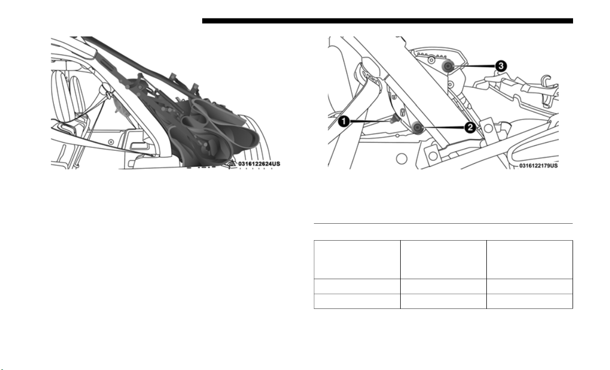
94 GETTING TO KNOW YOUR VEHICLE
Soft Top In Place
6. Using the provided #40 Torx h
ead driver and ratchet,
tighten the Torx screws by turning them clockwise.
Secure them until they are snug (refer to the table below
for recommended torque specifications), being careful
not to cross-thread the screws or overtighten. Repeat on
the opposite side.
Lift Assist Mechanism In Place
1 — Lock Position
2 — Torx Head Screw
3 — Torx Head Screw
Torque
Specification For
Torx Screws
Maximum Minimum
119.5 In-lbs 150.5 In-lbs 106.2 In-lbs
13.5 N·m 17.0 N·m 12.0 N·m
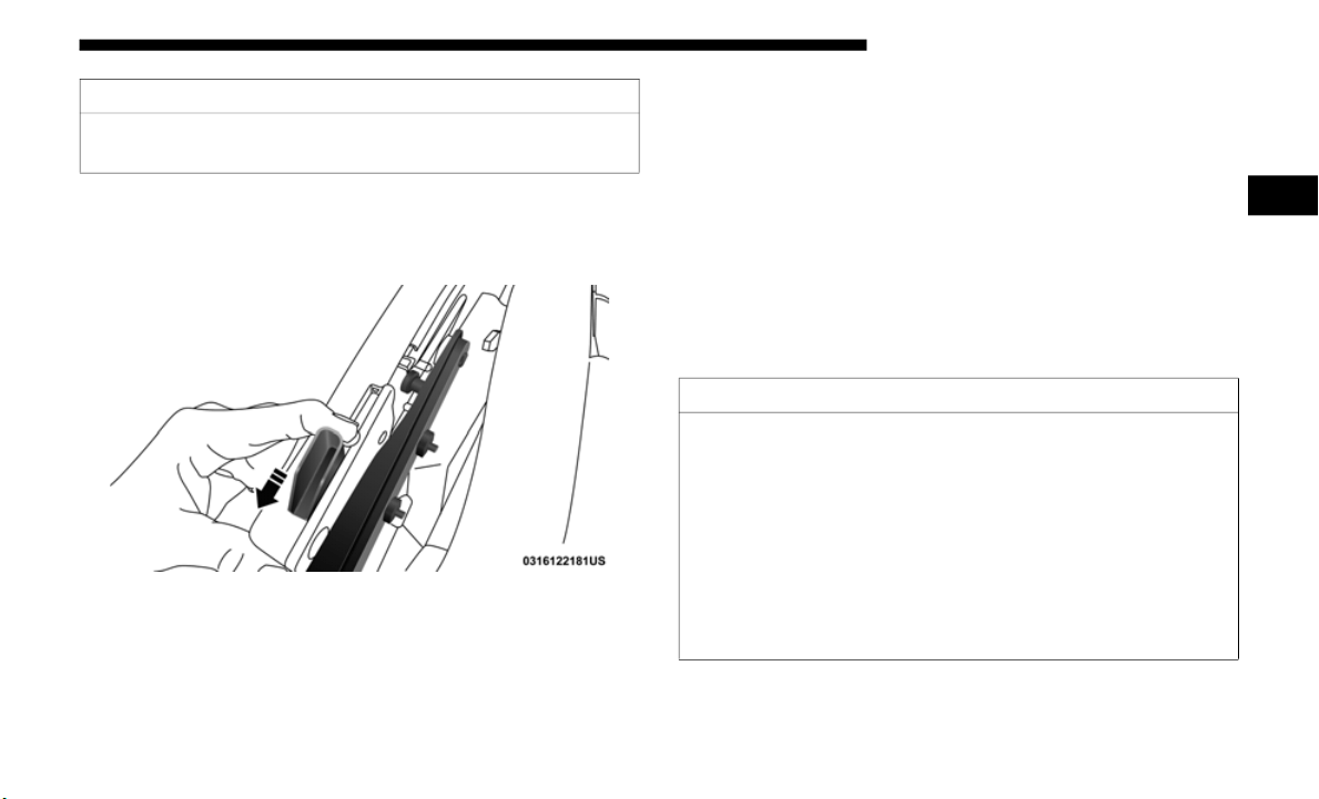
GETTING TO KNOW YOUR VEHICLE 95
(Continued)
7. While pulling the release lever on the top of the rail rear-
ward, place the side link into the guide track on the top of
the rail
then release the lever.
Step Seven
8. Unsnap and remove the black boot cover. This cover
should
be discarded. It was intended as a protective cover
for shipping only.
NOTE:
A visual instruction sheet is included with the vehicle.
9. Raise the soft top. Refer to “Raising The Soft Top” in this
section
.
NOTE:
Be sure the wire harness in the left rear corner is not tangled
in the s
oft top bows before you lift the top.
FREEDOM TOP THREE-PIECE MODULAR HARD
TOP — IF EQUIPPED
CAUTION!
Do not overtighten the screws. You can strip the screws if
they are
overtightened.
CAUTION!
• The hard top is not designed to carry any additional
loads, s
uch as after-market roof racks, spare tires,
building materials, hunting or camping supplies, etc.
For optional Mopar accessory roof racks, refer to the
Roof Luggage Rack portion of this Owner’s Manual for
additional information.
• Do not move your vehicle until the top has been either
fully at
tached to the front header, sport bar, and body
side or fully removed.
2
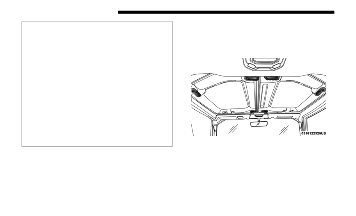
96 GETTING TO KNOW YOUR VEHICLE
Front Panel(s) Removal
NOTE:
The left side panel must be removed before removing the
right sid
e panel.
1. Fold down the sun visor against the windshield.
2. Turn
the three L-shaped locks on the left side panel (one
at the
front, the rear, and outside), unlocking them from
the roof.
Roof Panel Lock Locations
3. Unlatch the left side header panel latch located at the top
of the
windshield.
Failure to follow these cautions may cause interior water
damage, s
tains or mildew:
• It is recommended that the top be free of water prior to
panel r
emoval. Removing the top, opening a door or
lowering a window while the top is wet may allow
water to drip into the vehicle’s interior.
• The hard top assembly must be positioned properly to
ensure
sealing. Improper installation can cause water to
leak into the vehicle’s interior.
• Careless handling and storage of the removable roof
panels
may damage the seals, causing water to leak into
the vehicle’s interior.
• The front panel(s) must be positioned properly to
ensure
sealing. Improper installation can cause water to
leak into the vehicle’s interior.
CAUTION! (Continued)
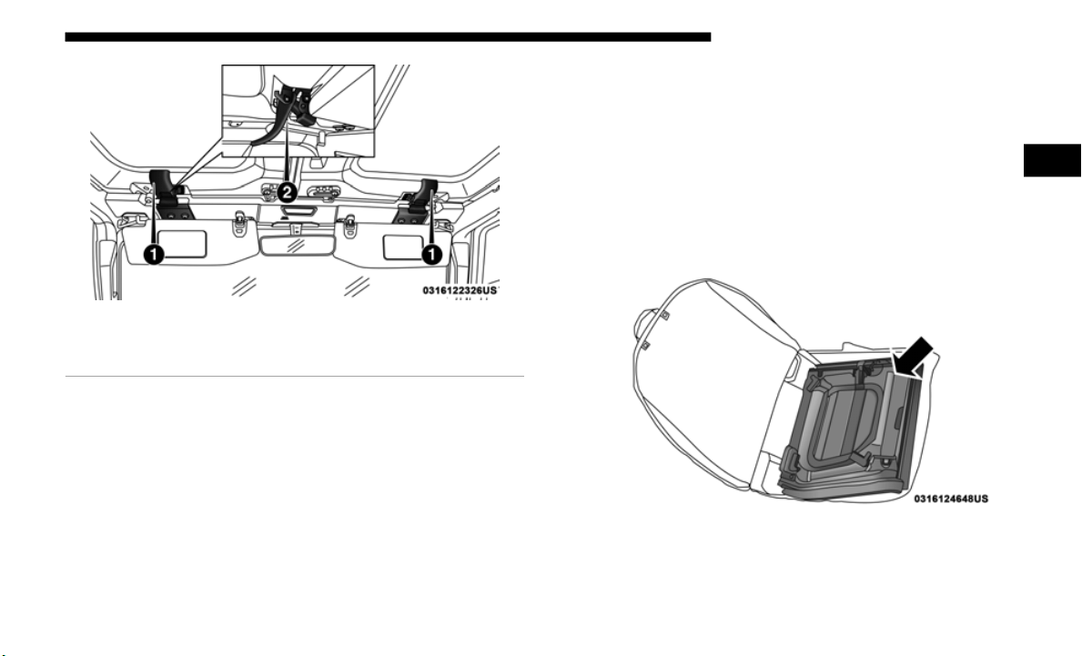
GETTING TO KNOW YOUR VEHICLE 97
Header Panel Latch Locations
4. Remove the left side panel.
5. Repea
t the steps above to remove the right side panel.
Freedom Top Storage Bag
Vehicles equipped with a Freedom Top Modular Hard Top,
come with a Freedom Top storage bag that allows you to
store your Freedom Top panels. The storage bag contains
two compartments and fits behind the rear seat.
Lay the bag for the Freedom Top panels down so the loops
and hooks
are facing upward. Unzip the bag and fold back
the outer flap.
NOTE:
Ensure the front Freedom Top panel latch is closed prior to
insertin
g the panel into the Freedom Top bag.
1. Insert the left side Freedom Top panel into the bag with
the lat
ches facing upward.
Left Panel — Latches Facing Upward
1 — Header Panel Latches
2 — Unlatched Position
2
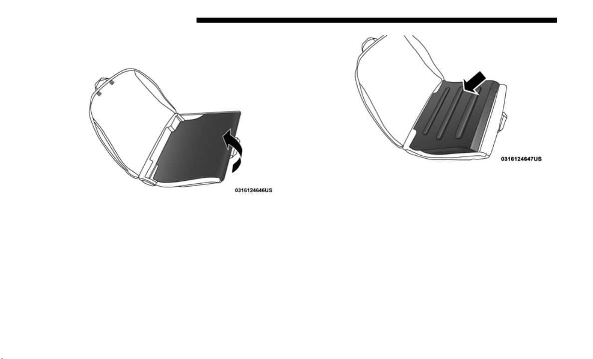
98 GETTING TO KNOW YOUR VEHICLE
2. Unfold the black panel divider (ensure the divider is
laying flat).
Fold Divider Over Left Panel
3. Insert the right side Freedom Top panel into the bag with
the lat
ches facing downward.
Right Panel — Latches Facing Downward
NOTE:
Ensure the front Freedom Top panel latch is closed prior to
i
nsertin
g the panel into the bag.
4. Unfold the outer flap and zip the Freedom Top bag
closed.
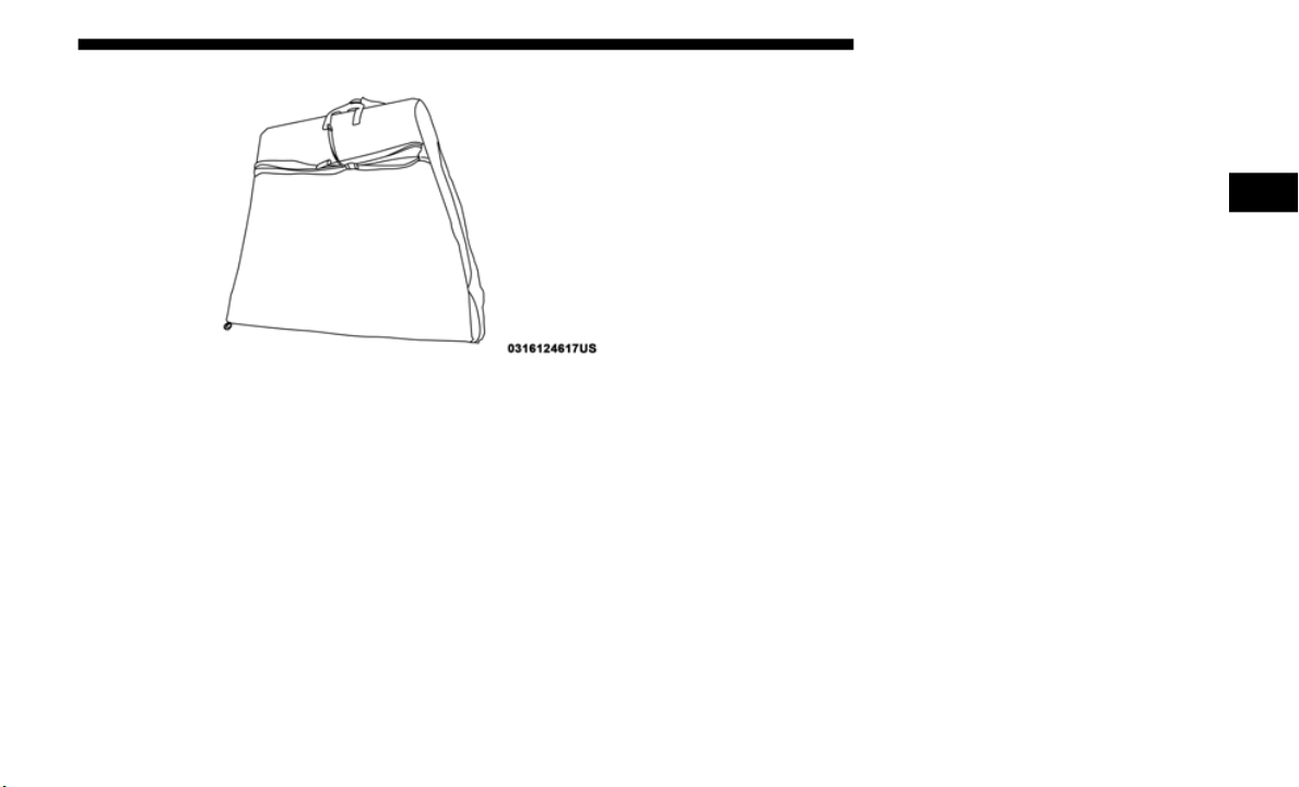
GETTING TO KNOW YOUR VEHICLE 99
Storage Bag Closed
5. Lift the Freedom Top bag into the vehicle with the hooks
and str
aps facing the back of the rear seat. Attach the clip
at the bottom of the bag to the child restraint anchorage,
located at the base of the rear seat.
6. Wrap the upper strap around the rear head restraints and
loop th
e strap through the buckle. Pull on the strap to
tighten the Freedom Top bag securely against the rear
seat.
Front Panel(s) Installation
1. Set the right side panel on the windshield frame with the
locating pin in the front receiver mounting hole followed
by the left side panel, making sure there is no overhang.
Also, make sure that the panels are sitting flush with the
body.
2. Reinstall the panel(s) using the same steps for removal in
reverse
order.
NOTE:
To prevent water leaks, the seals and Freedom Top Panels
should b
e clear of any dust and debris prior to reinstallation.
Rear Hard Top Removal
1. Remove both front panels. Refer to “Front Panel(s)
Removal” in this section.
2. Open both doors.
2
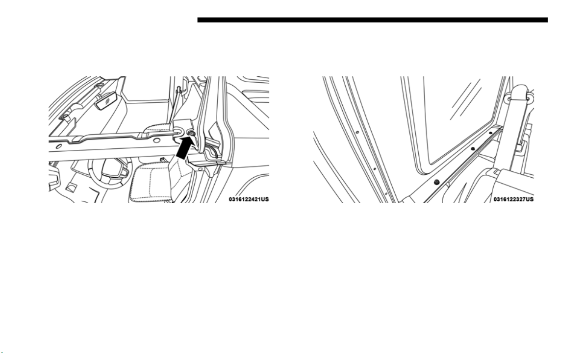
100 GETTING TO KNOW YOUR VEHICLE
3. Using the provided #50 Torx head driver and ratchet,
remove the two Torx head screws that secure the hard top
at the B-pillar (near the top of the front doors).
Step Three
4. Remove the six Torx head screws that secure the hard top
to the vehicle (along the interior bodyside — three screws
on each side) using the #50
Torx head driver.
Step Four
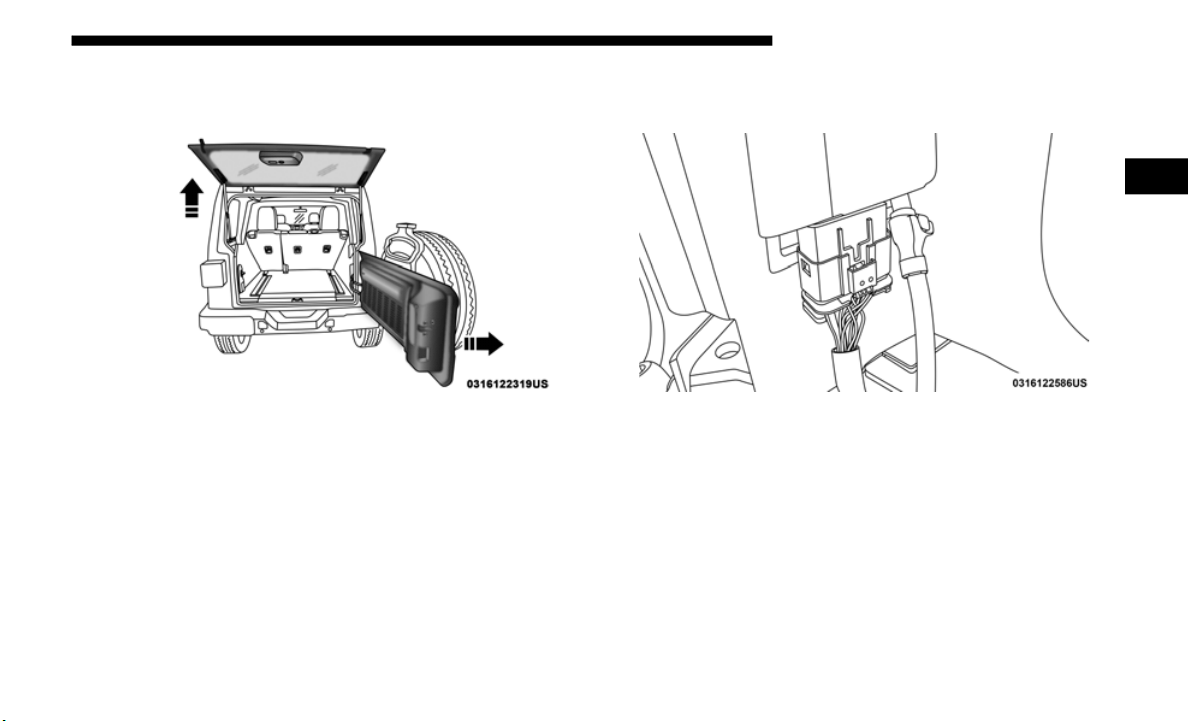
GETTING TO KNOW YOUR VEHICLE 101
5. Open the swing gate all the way to ensure clearance of the
rear window glass. Lift the rear window glass.
Step Five
6. Locate the wire harness and washer hose on the left rear
inside corner of the vehicle.
Wire Harness
2
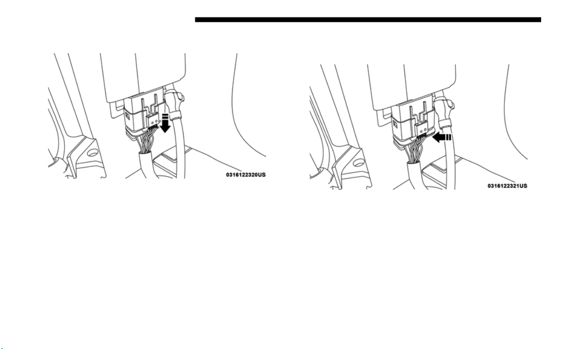
102 GETTING TO KNOW YOUR VEHICLE
7. Release the locking tab by pushing it downward.
Push Locking Tab Downward
8. To remove the wiring harness, push the tab inward while
pulling downward to disconnect.
Push Tab Inward
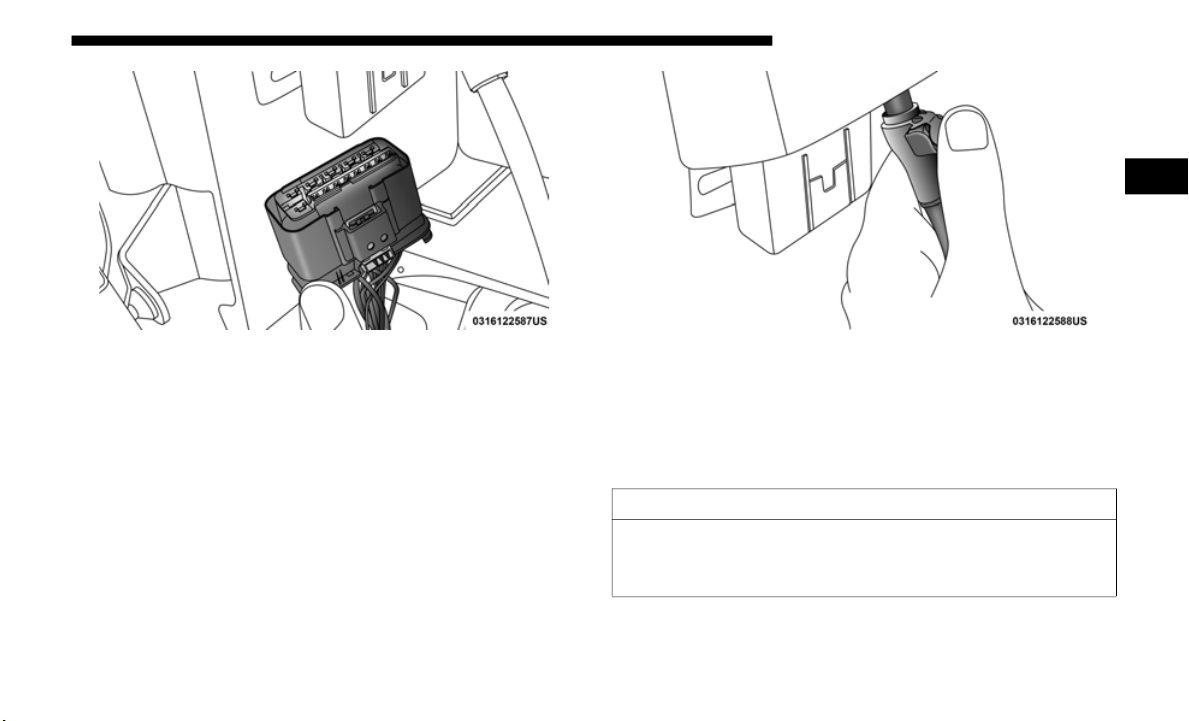
GETTING TO KNOW YOUR VEHICLE 103
Pull Wiring Harness To Separate
9. To remove the washer hose, push the release button on
hose c
onnector, and pull downward.
Release Button On Hose
10. Lower the rear window, and close the swing gate.
11. Remove the hard top from the vehicle. Place the hard top
on a s
oft surface to prevent damage.
CAUTION!
The removal of the Freedom Top requires four adults
located
on each corner. Failure to follow this caution
could damage the Freedom Top.
2

104 GETTING TO KNOW YOUR VEHICLE
Rear Hard Top Installation
NOTE:
If the door frames are installed from soft top usage, they
must be
removed prior to installation of the hard top. Refer
to “Door Frame” in this section for installation procedures.
1. Inspect the hard top seals for damage and replace if
necess
ary.
2. Install the hard top using the same steps for removal in
revers
e order.
Make sure that the hard top is sitting flush with the body
at the
sides and check to ensure that there is a uniform
gap between the lift glass and hard top.
NOTE:
The Torx fasteners that attach the hard top to the body
should
be torqued as follows using the provided #50 Torx
head dr
iver and ratchet:
• Hard top to B-pillar: 119 in-lb
+/- 23 in-lb (13.5 N·m +/
- 2.7 N·m)
• Hard top to J-rail: 154 in-lb
+/- 30 in-lb (17.5 N·m +/-
3.5 N·m)
DOOR FRAME
WARNING!
• Do not drive your vehicle on public roads with the door
frame(
s) removed as you will lose the protection that
they can provide. This procedure is furnished for use
during off-road operation only.
• Do not drive your vehicle on public roads with the
doors re
moved as you will lose the protection that they
can provide. This procedure is furnished for use during
off-road operation only.
CAUTION!
• O
pening a door or lowering a window while the top is
wet ma
y allow water to drip into the vehicle's interior.
• Careless handling and storage of the removable door
frame(
s) may damage the seals, causing water to leak
into the vehicle's interior.
• The door frame(s) must be positioned properly to
ensure
sealing. Improper installation can cause water to
leak into the vehicle's interior.
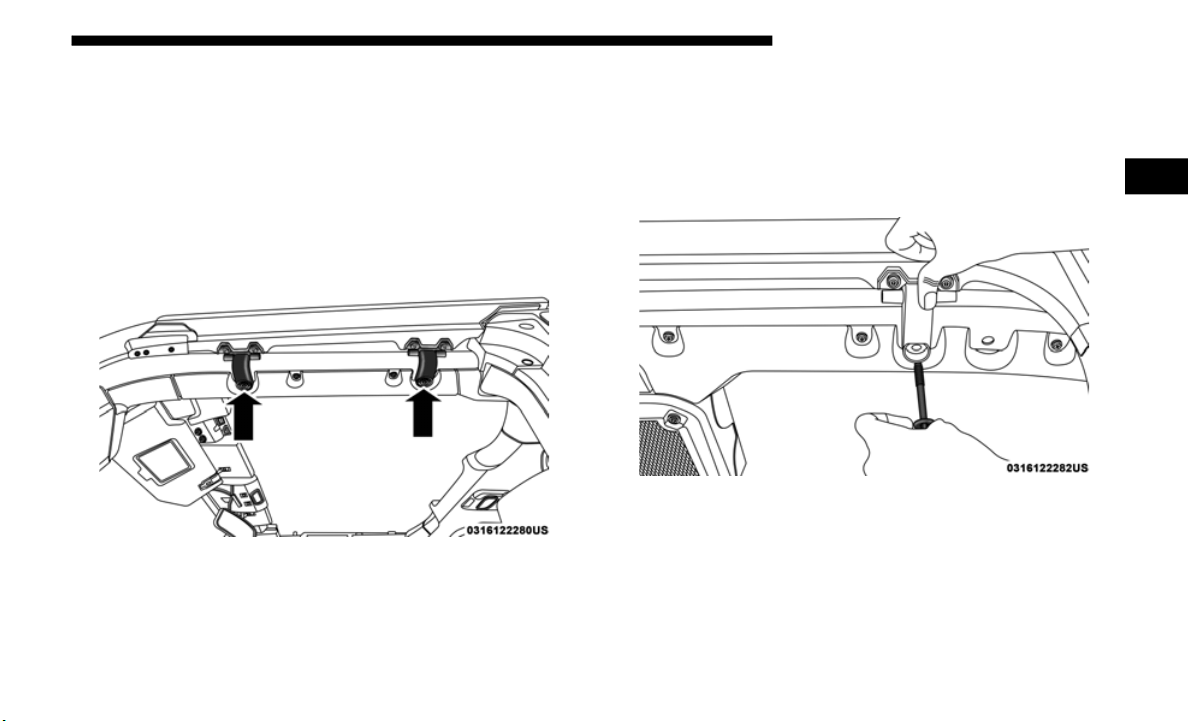
GETTING TO KNOW YOUR VEHICLE 105
Door Frame Removal
NOTE:
In four door models, the rear door frames must be removed
first, f
ollowed by the front door frames.
1. Using the provided #40 Torx h
ead driver and ratchet,
loosen the Torx screws located on the underside of each
door frame (two per door).
Door Frame Screw Locations
2. Once all the way loosened, remove the screws by pulling
downward.
N
OTE:
Screws will not fall out once completely loose, as they are
held in
place by an internal mechanism.
Remove Screws From Below Frame
2
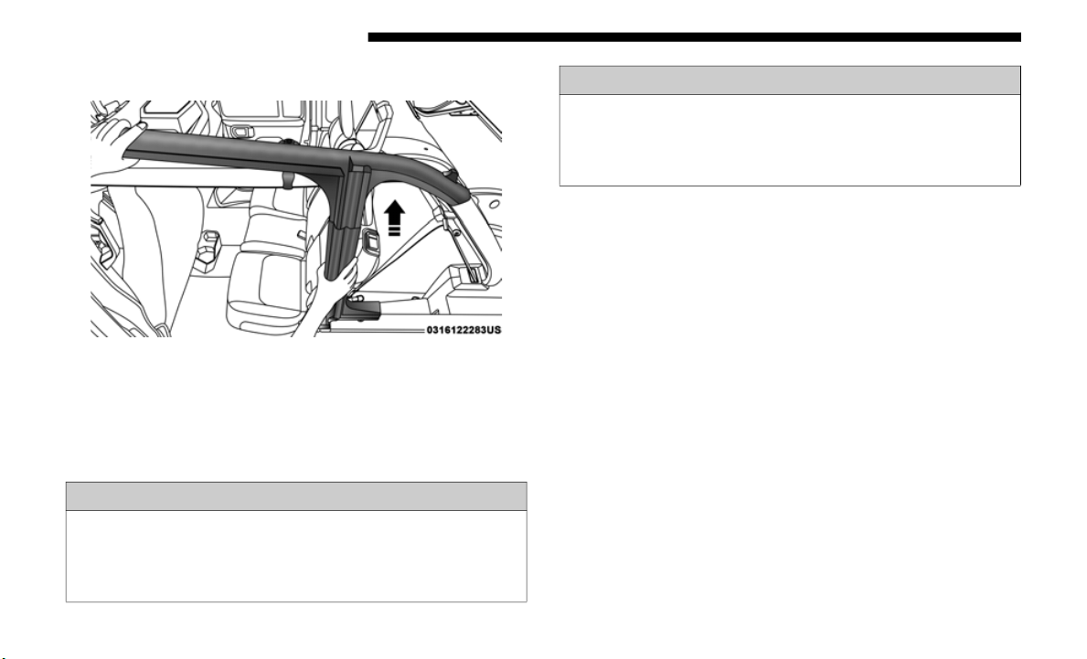
106 GETTING TO KNOW YOUR VEHICLE
(Continued)
3. Lift the frame upward, removing it from the vehicle.
Step Three
4. Store screws in a secure location.
5. Repea
t procedure on the front door frame (four door
models)
.
Door Frame Installation Four Door Models — If
Equipped
1. Install the front door rail first.
2. Carefully place the front door rail in the rubber seal at the
top of
the windshield, and line up the holes for the Torx
head screws (two for each door).
3. Swing the frame bracket around the side of the rail, and
insert
the screws from underneath. Tighten with #40 Torx
head dri
ver until they are snug, being careful not to
cross-thread the screws or overtighten. Refer to the table
below for the appropriate torque specifications for the
door rail screws.
WARNING!
• Do not drive your vehicle on public roads with the door
frame(s
) removed as you will lose the protection that
they can provide. This procedure is furnished for use
during off-road operation only.
• Do not drive your vehicle on public roads with the
doors removed as you will lose the protection that they
can provide. This procedure is furnished for use during
off-road operation only.
WARNING! (Continued)
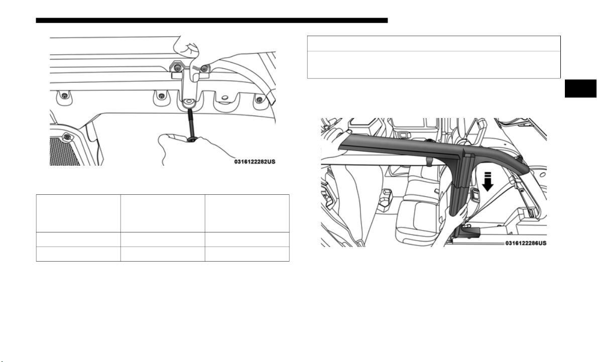
GETTING TO KNOW YOUR VEHICLE 107
Step Three
4. Set the rear door frame pin into the hole on top of the
body sid
e, just behind the rear door opening.
Step Four
Torque
S
pecific
ation For
Torx Screws
Maximum Minimum
8.8 In-lbs 11.0 In-lbs 6.6 In-lbs
12 N·m 15 N·m 9 N·m
CAUTION!
Do not overtighten the screws. You can strip the screws if
they are
overtightened.
2
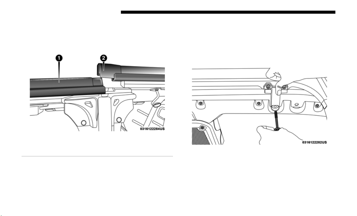
108 GETTING TO KNOW YOUR VEHICLE
5. Carefully position the top of the door frame onto the rear
of the front door rail, making sure rubber seals lay flat.
Ensure the seals are installed correctly to avoid water
leaks.
Position Of Frame Above Door
6. Swing the frame bracket around the side of the rail, and
insert the screws from underneath. Tighten with #40 Torx
head dri
ver until they are snug, being careful not to
cross-thread the screws or overtighten. Refer to the table
above for the appropriate torque specifications for the
door rail screws.
Step Six
1 — Front Door Rail
2 — Rear Door Frame

GETTING TO KNOW YOUR VEHICLE 109
Door Frame Installation Two Door Models — If
Equipped
1. Carefully place the front door rail in the rubber seal at the
top of the windshield, and line up the holes for the Torx
head screws (two for each door).
2. Swing the frame bracket around the side of the rail, and
insert
the screws from underneath. Tighten with #40 Torx
head dri
ver until they are snug, being careful not to
cross-thread the screws or overtighten. Refer to the table
below for the appropriate torque specifications for the
door rail screws.
Step Two
Torque
Specific
ation For
Torx Screws
Maximum Minimum
8.8 In-lbs 11.0 In-lbs 6.6 In-lbs
12 N·m 15 N·m 9 N·m
CAUTION!
Do not overtighten the screws. You can strip the screws if
they are
overtightened.
2

110 GETTING TO KNOW YOUR VEHICLE
SOFT TOP TWO DOOR MODELS — IF EQUIPPED
If the temperature is below 72°F (24°C) and/or the top has
been folded down for a period of time, the top will appear to
have shrunk when you raise it, making it difficult to put up.
This is caused by a natural contraction of the vinyl or acrylic
materials of the fabric top.
Place the vehicle in a warm area. Pull steadily on the top
fabric.
The vinyl will stretch back to its original size and the
top can then be installed. If the temperature is 41°F (5°C) or
below, do not attempt to put the top down or roll the rear
or side curtains.
WARNING!
• Do not drive the vehicle with the rear window up/
removed
unless the quarter windows are also removed.
Dangerous exhaust gases could enter the vehicle
causing harm to the driver and passengers.
• The fabric quarter windows and fabric top are designed
only for
protection against the elements. Do not rely on
them to contain occupants within the vehicle or to
protect against injury during an accident. Remember,
always wear seat belts.
• Make sure hands and fingers are clear of all pinch
points
when installing and removing the soft tops. The
lift assist mechanism and side bows may cause serious
injury if fingers or hands get caught in between.
CAUTION!
The soft top is not designed to carry any additional loads
such as
roof racks, spare tires, building, hunting, or
camping supplies, and/or luggage, etc. Also, it was not
designed as a structural member of the vehicle and, thus,
cannot properly carry any additional loads other than
environmental (rain, snow, etc.).

GETTING TO KNOW YOUR VEHICLE 111
(Continued)
CAUTION!
• Do not run a fabric top through an automatic car wash.
Window
scratches and wax build up may result.
• Do not lower the top when the temperature is below
41°F (5
°C). Damage to the top may result.
• Do not move your vehicle until the top has been either
fully a
ttached to the windshield frame, or fully
lowered.
• Do not lower the top with the windows installed.
Window
and top damage may occur.
• Refer to “Appearance Care For Fabric Top Models” in
“Bodywork
” in “Servicing And Maintenance” for
further information. It contains important information
on cleaning and caring for your vehicle's fabric top.
• Do not use any tools (screwdrivers, etc.) to pry or force
any of t
he clamps, clips, or retainers securing the soft
top. Do not force or pry the soft top framework when
opening or closing. Damage to the top may result.
Failure to follow these cautions may cause interior water
damage, stains or mildew on the top material:
• It is recommended that the top be free of water prior to
opening it. Operating the top, opening a door or
lowering a window while the top is wet may allow
water to drip into the vehicle's interior.
• Careless handling and storage of the soft top may
damage
the seals, causing water to leak into the
vehicle's interior.
• The soft top must be positioned properly to ensure
sealin
g. Improper installation can cause water to leak
into the vehicle's interior.
CAUTION! (Continued)
2
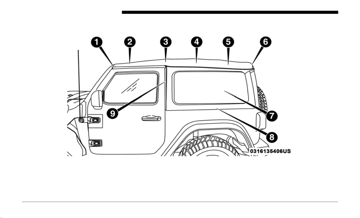
112 GETTING TO KNOW YOUR VEHICLE
Lowering The Soft Top
Side View Top And Components
1 — #1 Bow 6 — #6 Bow
2 — #2 Bow 7 — Rear Quarter Window
3 — #3 Bow 8 — Lower Window Retainer
4 — #4 Bow 9 — Front Window Retainer
5 — #5 Bow

GETTING TO KNOW YOUR VEHICLE 113
Rear View Top And Components
1 — Rear Window Retainer Attachment Points
2 — Quarter Window Pillars
3 — Swing Gate Bar Retainers
2
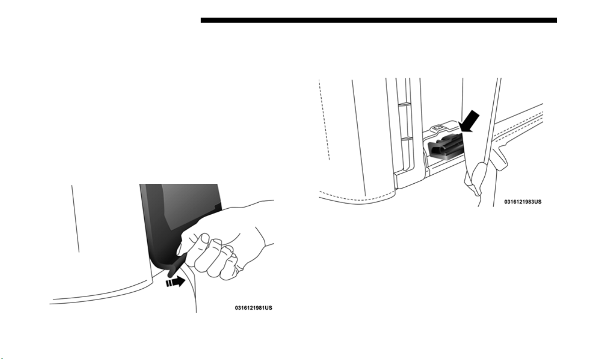
114 GETTING TO KNOW YOUR VEHICLE
NOTE:
The rear window and rear quarter windows must be r
emoved
before lowering the soft top to prevent damage to the top.
Clean the side and rear windows before removal to assist in
preventing scratching during removal of the soft top. If the
plastic retainers are difficult to operate due to road dust, etc.,
clean them with a mild soap solution and a small brush.
Cleaning products are available through an authorized dealer.
Remove The Rear Window:
1. With the swing gate open, remove the rear window’s
plastic
retainers from the lower right and left corners.
Step One
2. G
rasp the swing gate bar, rotate it outward and upward
releasi
ng it from both the right and left retainers. Store in
a safe location.
Step Two (Left Side Shown)

GETTING TO KNOW YOUR VEHICLE 115
3. While holding the window in place, slide the tailgate bar
to the left separating it from the rear window. Store
windows in soft top window bag, or a safe location.
Step Three
4. Remove the plastic retainers from both quarter window
pillars.
Step Four
2

116 GETTING TO KNOW YOUR VEHICLE
5. While keeping the rear window level, slide to the left
until it is completely separate from its retainer. Do not
pull downward while removing the rear window.
Damage to the retainer could result.
Step Five
Remove The Right And Left Quarter Windows:
1. Through the rear opening, push the bottom corner
outward
and release tab from the bottom of the window
pillar.
Step One

GETTING TO KNOW YOUR VEHICLE 117
2. Undo the hook-and-loop fastener located at the upper
front corner of each quarter window.
Hook-And-Loop Fastener Location
3. Starting at the rear of the vehicle, remove plastic retainer
from along the bottom of the window moving toward the
front of the vehicle.
Step Three
2

118 GETTING TO KNOW YOUR VEHICLE
4. Remove plastic retainer from bottom to top of the
window.
Step Four
5. While keeping the window level, slide rearward until it is
complet
ely separate from its retainer. Do not pull down-
ward while removing the window. Damage to the
r
etainer
could result.
Step Five
6. Store in soft window bag or a safe location.
NOTE:
Ref
er to “Soft Top Window Storage Bag” in this section for
i
nformat
ion on the use of the storage bag.

GETTING TO KNOW YOUR VEHICLE 119
Lowering The Soft Top Into Sunrider Position
1. After removing the rear window and quarter panel
windows,
move to the front of the vehicle.
2. Fo
ld both sun visors forward against the windshield.
3
. Relea
se the header latches from the crossbar by pulling
the han
dle downward. Make sure the hook is disengaged
from its receiver.
Step Three
4. From both the left and right sides, lift up on the #1 Bow
of the
soft top to start the operation.
Step Four
2
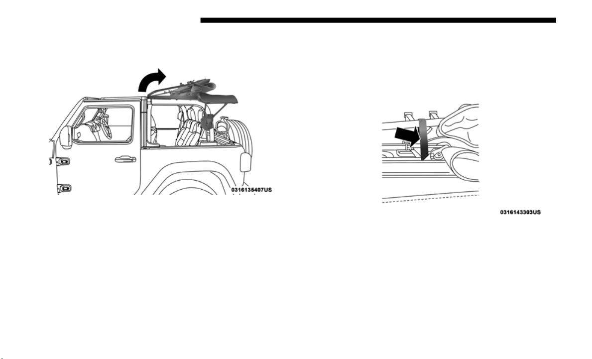
120 GETTING TO KNOW YOUR VEHICLE
5. Move to the side of the vehicle and use the side link to
fold the soft top rearward into the Sunrider position.
Step Five
NOTE:
If leaving the soft top in the Sunrider position, secure the top
by using t
he two hook-and-loop fasteners provided in the
center console.
Secured Top When In Sunrider Position
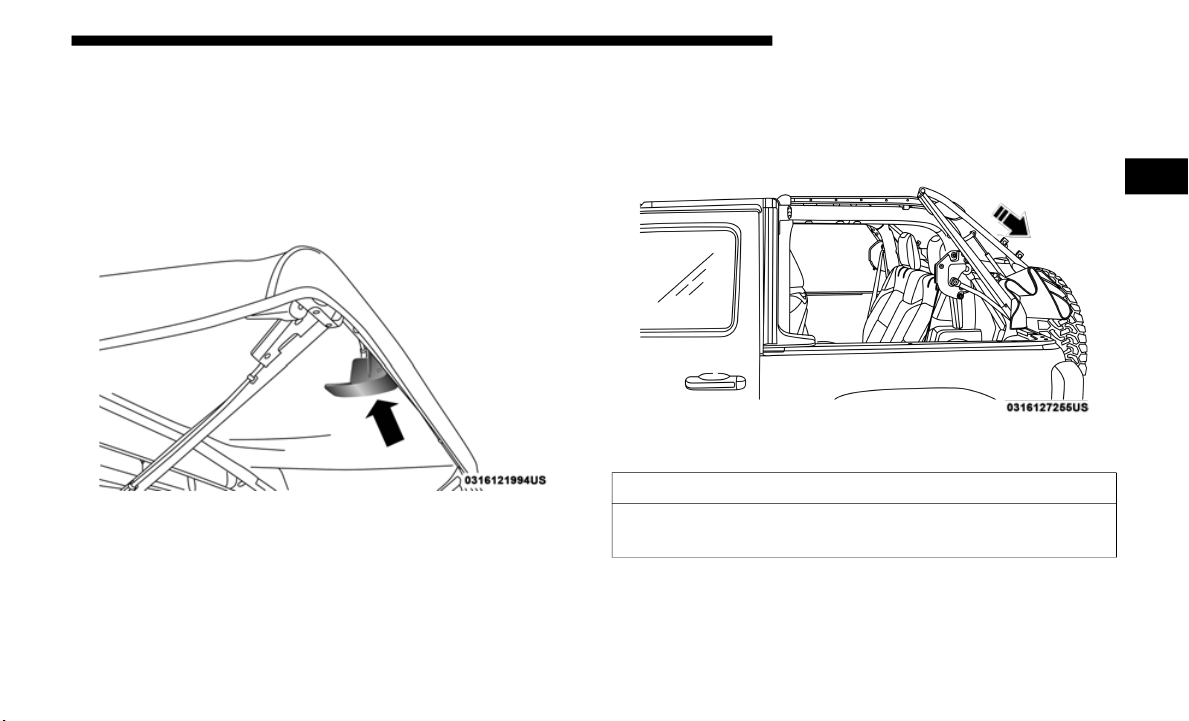
GETTING TO KNOW YOUR VEHICLE 121
Lowering The Soft Top Into Fully Lowered Position
1. From the Sunrider position, remove straps if previously
secured
and move to the rear of the vehicle.
2. L
ocate the Sunrider latch beneath the #6 Bow of the soft
t
op on
the left side.
Sunrider Latch Beneath #6 Bow
3. P
ull the latch downward to release the top, and allow the
soft to
p to slide rearward freely in the guide tracks to the
stowed position.
Step Three
CAUTION!
Failure to follow the next steps could result in damage to
the Soft
Top or vehicle.
2
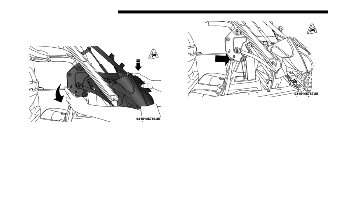
122 GETTING TO KNOW YOUR VEHICLE
4. While pushing downward slightly on the folded soft top,
slide the lock lever on the left and right side lift assist
mechanisms to the “lock” position.
Step Four
Lock Position
5. Once the lock is in the “lock” position, push downward
on each
side of the folded soft top to ensure it is secure.
An audible “click” may be heard.

GETTING TO KNOW YOUR VEHICLE 123
NOTE:
Secure the top by using the two hook-and-loop fasteners
provided
in the center console.
Secured Top When In Fully Lowered Position
Soft Top Window Storage Bag
To safely store the soft top rear window, and rear quarter
windows, proceed as follows:
NOTE:
The swing gate bar, once removed from the rear window,
d
oes not st
ore in the soft window storage bag.
1. With the bag opened completely, fold both fabric dividers
downward
and lay the first quarter window all the way
to the right side with the inside of the window facing
downward and the window pillar to the outside.
NOTE:
The quarter windows are marked “1” and “2” on the inside
o
f the wi
ndow pillar.
Window Pillar Number Location
2
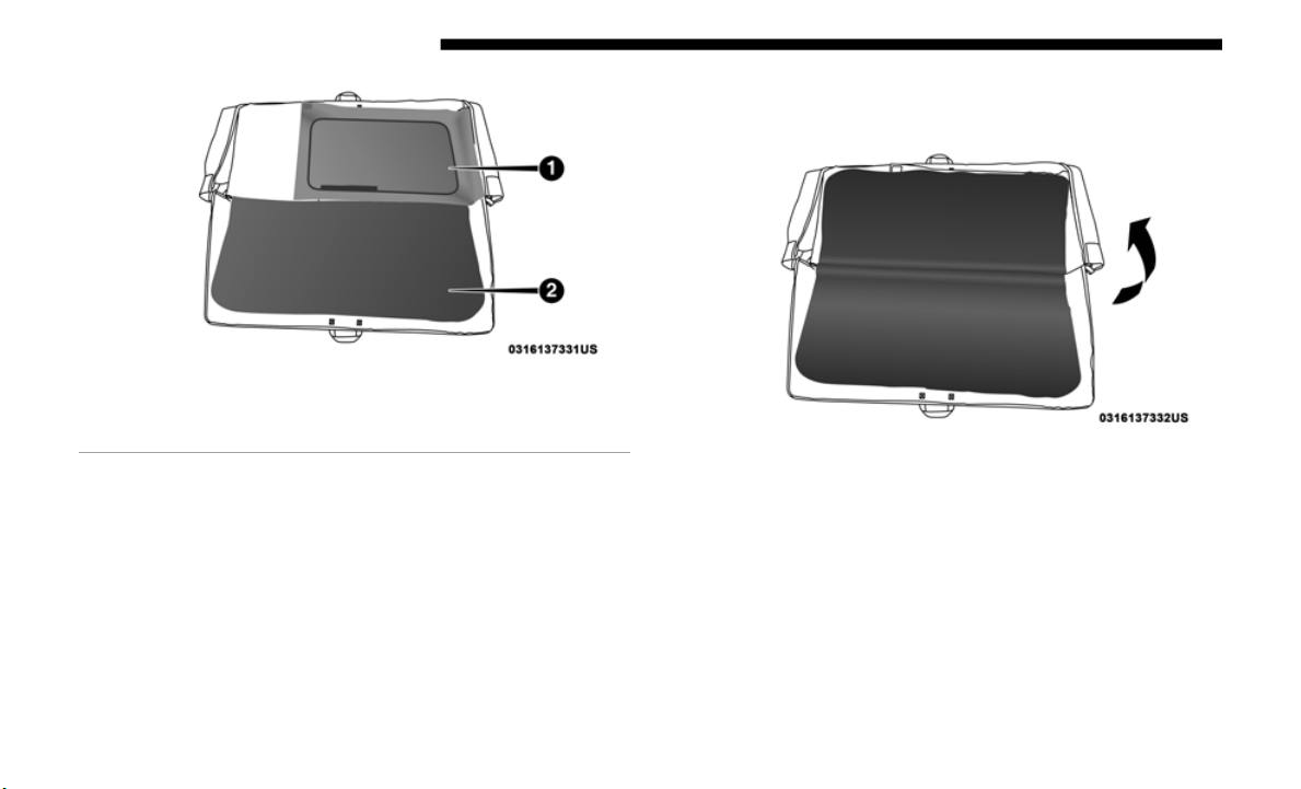
124 GETTING TO KNOW YOUR VEHICLE
Step One
2. Fold the first divider upward, covering the first quarter
window.
Ste
p Two
1 — Quarter Window Facing Downward
2 — Both Dividers Folded Down
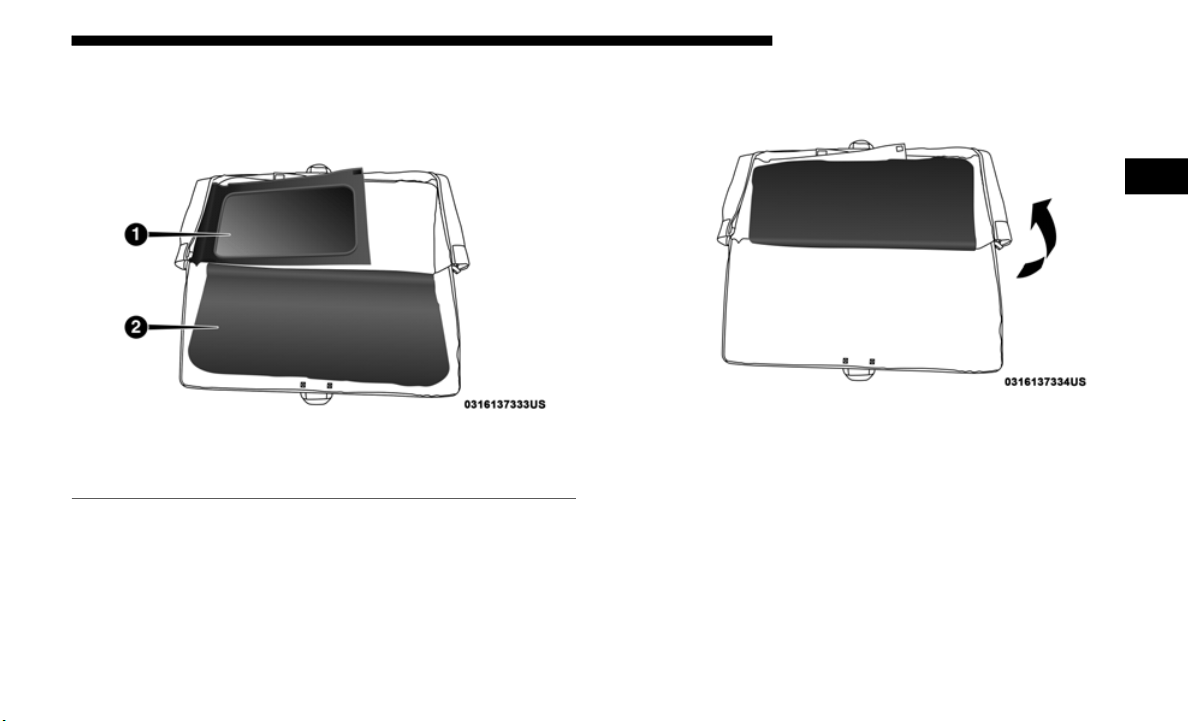
GETTING TO KNOW YOUR VEHICLE 125
3. Lay the second quarter window on top of the first divider
all the way to the left side with the inside of the window
facing downward and the window pillar to the outside.
Step Three
4. Fold the second divider upward, covering the second
quarter window.
Step Four
1 — Quarter Window Facing Downward
2 — Second Divider Folded Down
2
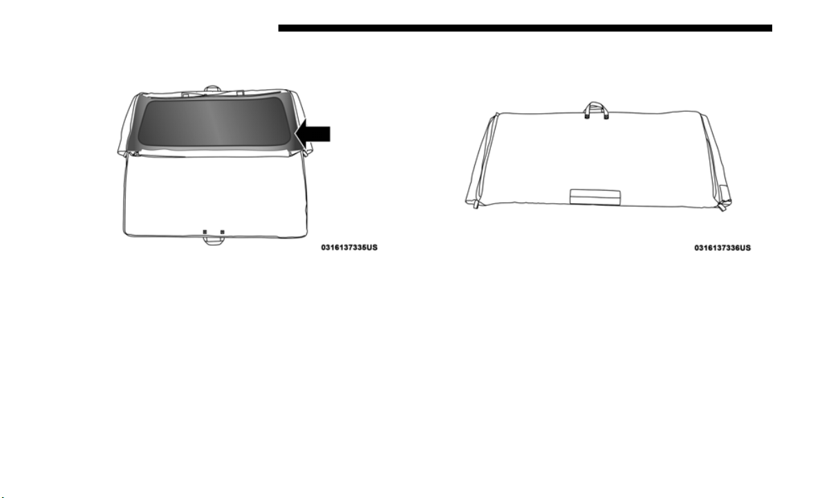
126 GETTING TO KNOW YOUR VEHICLE
5. Lay the rear window on top of the second divider.
Step Five
6. Close the storage bag and store in a safe location.
Step Six
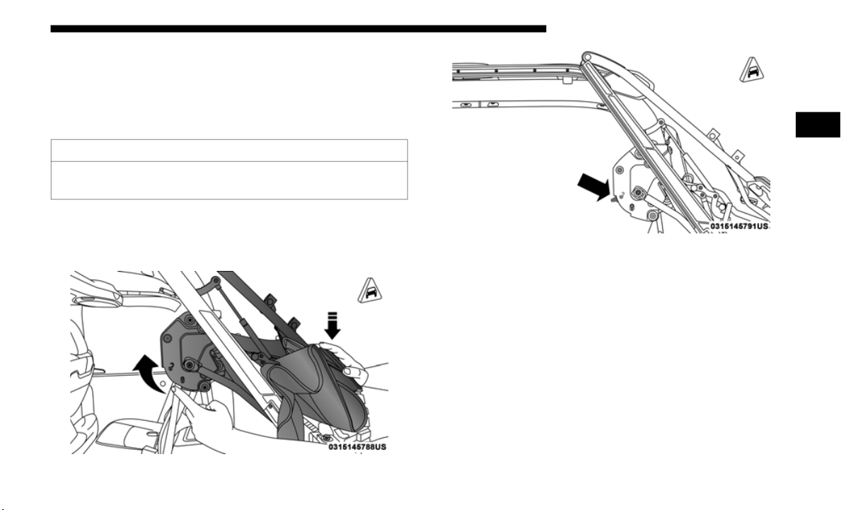
GETTING TO KNOW YOUR VEHICLE 127
Raising The Soft Top
Raising The Soft Top From The Fully Lowered Position
1. From the fully lowered position, remove straps if previ-
ously se
cured.
2. W
hile pushing down on the rear of the top, slide the lock
lever o
n the left and right side Lift Assist Mechanisms to
the “unlock” position.
Push Down While Unlocking
Unlocked Position
CAUTION!
Failure to follow the next steps could result in damage to
t
he Soft
Top or vehicle.
2
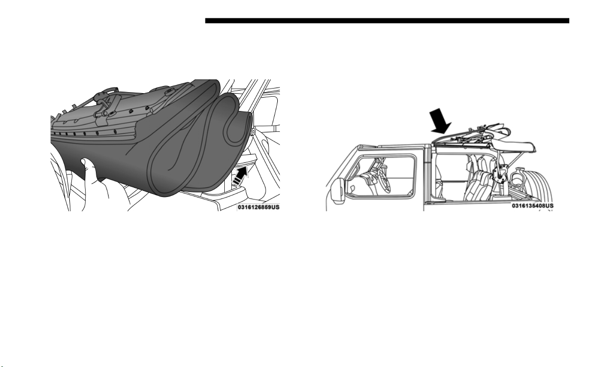
128 GETTING TO KNOW YOUR VEHICLE
3. Push up and forward from the #5 Bow along the guide
track until it locks into the Sunrider position with an
audible “click”.
Step Three
4. Gently pull rearward on the #6 Bow to ensure the top is
locked i
n the Sunrider position.
5. Using the side link, lift and push the soft top toward the
front o
f the vehicle guiding the top into the closed posi-
tion.
Side Link Location

GETTING TO KNOW YOUR VEHICLE 129
Lower Top Into Closed Position
6. From inside the vehicle, pull the handle on the header
latch d
ownward to engage the hook into its receiver.
Repeat on the other side.
Step Six
2

130 GETTING TO KNOW YOUR VEHICLE
7. Pull the handle back upward while squeezing the latch
plate, locking the latch into place.
Step Seven
Install The Right And Left Quarter Windows
1. From the rear of the vehicle, guide the top of the window
into th
e retainer and slide forward while keeping the
window level. Repeat on the other side.
Step One

GETTING TO KNOW YOUR VEHICLE 131
2. Place the top of the quarter window pillar into the top
cover, and insert the bottom tab into the clip.
Step Two
Step Two
CAUTION!
Failure to follow all Quarter Window Install steps could
result i
n damage to the Soft Top or vehicle.
2

132 GETTING TO KNOW YOUR VEHICLE
3. Engage the retainers on the front of the windows,
ensuring they are fully engaged, followed by the retainers
along the bottom of the windows.
Fully Engage Quarter Window Retainers
NOTE:
It is critical that t
he retainers are fully engaged before the
vehicle resumes motion.
4. Tuck Flap 1 between Flap 2 and Flap 3 on Soft Top Cover.
Flaps On
Soft Top Cover
1 — Retainer At Front Of Quarter Window
2 — Retainer At Bottom Of Quarter Window
1 — Flap 1
2 — Flap 2
3 — Flap 3
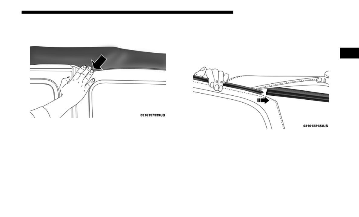
GETTING TO KNOW YOUR VEHICLE 133
5. Secure the hook-and-loop fastener at the upper front
corner of each quarter window by pressing firmly.
Firmly Secure Hook-And-Loop Fastener
Install The Rear Window
1. Guide the rear window into the retainer from left to right
while kee
ping the window level.
Step One
2
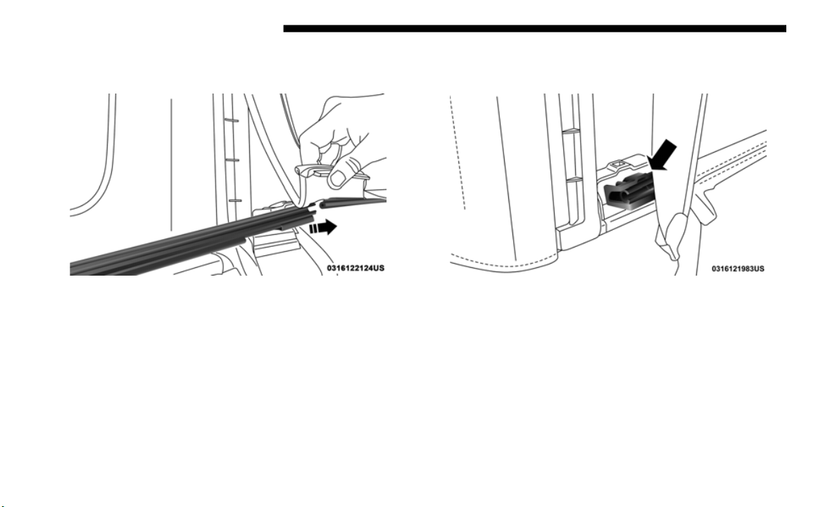
134 GETTING TO KNOW YOUR VEHICLE
2. Insert the tailgate bar into the retainers at the bottom of
the window from left to the right.
Step Two
3. Rotate the swing gate bar into the left and right side
retainers.
Step Three
4. Line up the rear window to the right si
de quarter
window first, and engage the plastic retainers.
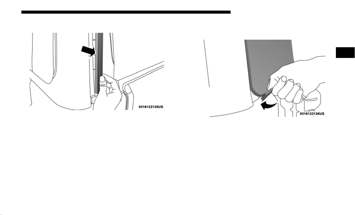
GETTING TO KNOW YOUR VEHICLE 135
5. Repeat with the left side quarter window.
Step Five
6. Engage the rear window retainers in the lower right and
left corners.
Step Six
2

136 GETTING TO KNOW YOUR VEHICLE
SOFT TOP FOUR DOOR MODELS — IF EQUIPPED
If the temperature is below 72°F (24°C) and/or the top has
been folded down for a period of time, the top will appear to
have shrunk when you raise it, making it difficult to put up.
This is caused by a natural contraction of the vinyl or acrylic
materials of the fabric top.
Place the vehicle in a warm area. Pull steadily on the top
fabric.
The vinyl will stretch back to its original size and the
top can then be installed. If the temperature is 41°F (5°C) or
below, do not attempt to put the top down or roll the rear
or side curtains.
WARNING!
• Do not drive the vehicle with the rear window up/
removed
unless the quarter windows are also removed.
Dangerous exhaust gases could enter the vehicle
causing harm to the driver and passengers.
• The fabric quarter windows and fabric top are designed
only for
protection against the elements. Do not rely on
them to contain occupants within the vehicle or to
protect against injury during an accident. Remember,
always wear seat belts.
• Make sure hands and fingers are clear of all pinch
points
when installing and removing the soft tops. The
lift assist mechanism and side bows may cause serious
injury if fingers or hands get caught in between.
CAUTION!
The soft top is not designed to carry any additional loads
such as
roof racks, spare tires, building, hunting, or
camping supplies, and/or luggage, etc. Also, it was not
designed as a structural member of the vehicle and, thus,
cannot properly carry any additional loads other than
environmental (rain, snow, etc.).

GETTING TO KNOW YOUR VEHICLE 137
(Continued)
CAUTION!
• Do not run a fabric top through an automatic car wash.
Window
scratches and wax build up may result.
• Do not lower the top when the temperature is below
41°F (5
°C). Damage to the top may result.
• Do not move your vehicle until the top has been either
fully a
ttached to the windshield frame, or fully
lowered.
• Do not lower the top with the windows installed.
Window
and top damage may occur.
• Refer to “Appearance Care For Fabric Top Models” in
“Bodywork
” in “Servicing And Maintenance” for
further information. It contains important information
on cleaning and caring for your vehicle's fabric top.
• Do not use any tools (screwdrivers, etc.) to pry or force
any of t
he clamps, clips, or retainers securing the soft
top. Do not force or pry the soft top framework when
opening or closing. Damage to the top may result.
Failure to follow these cautions may cause interior water
damage, stains or mildew on the top material:
• It is recommended that the top be free of water prior to
opening it. Operating the top, opening a door or
lowering a window while the top is wet may allow
water to drip into the vehicle's interior.
• Careless handling and storage of the soft top may
damage
the seals, causing water to leak into the
vehicle's interior.
• The soft top must be positioned properly to ensure
sealin
g. Improper installation can cause water to leak
into the vehicle's interior.
CAUTION! (Continued)
2
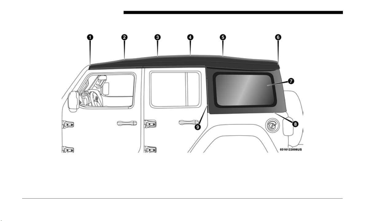
138 GETTING TO KNOW YOUR VEHICLE
Lowering The Soft Top
Side View Top And Components
1 — #1 Bow 6 — #6 Bow
2 — #2 Bow 7 — Rear Quarter Window
3 — #3 Bow 8 — Lower Window Retainer
4 — #4 Bow 9 — Front Window Retainer
5 — #5 Bow
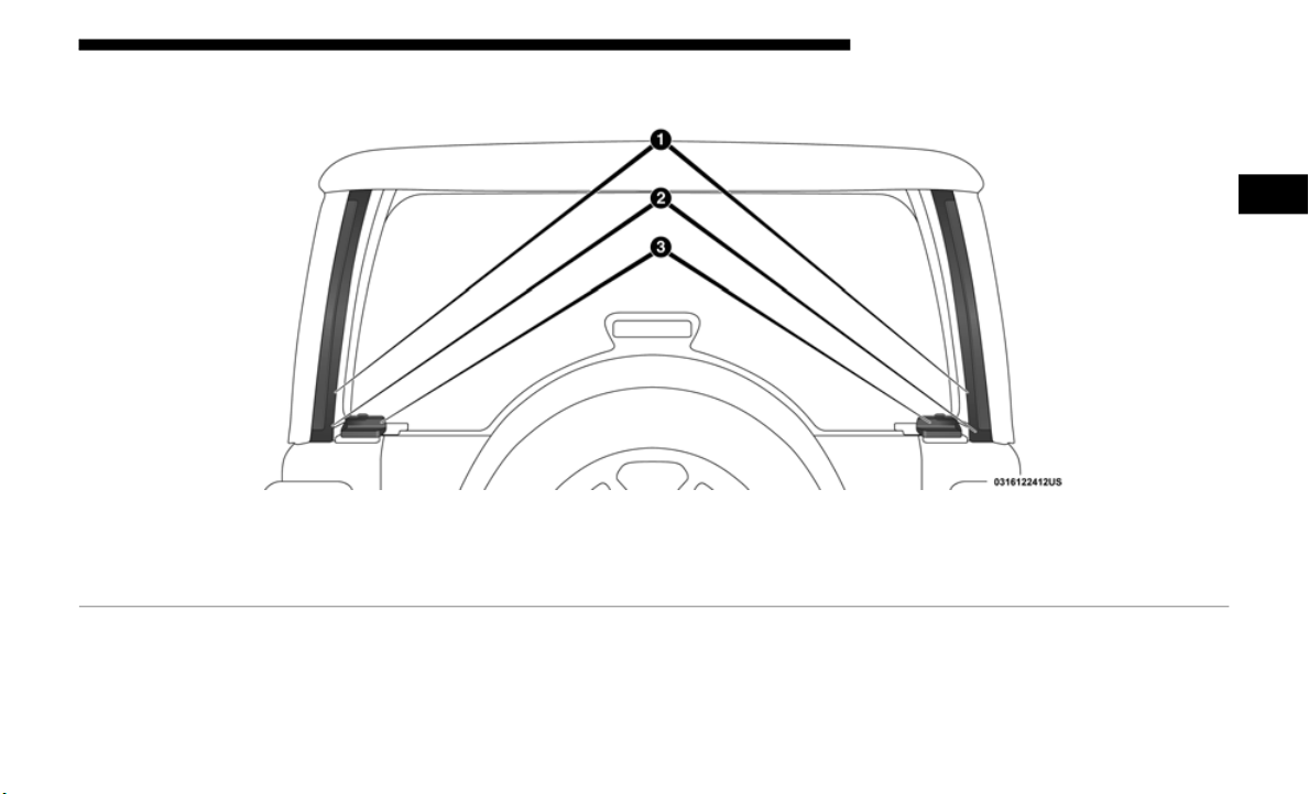
GETTING TO KNOW YOUR VEHICLE 139
Rear View Top And Components
1 — Rear Window Retainer Attachment Points
2 — Quarter Window Pillars
3 — Swing Gate Bar Retainers
2
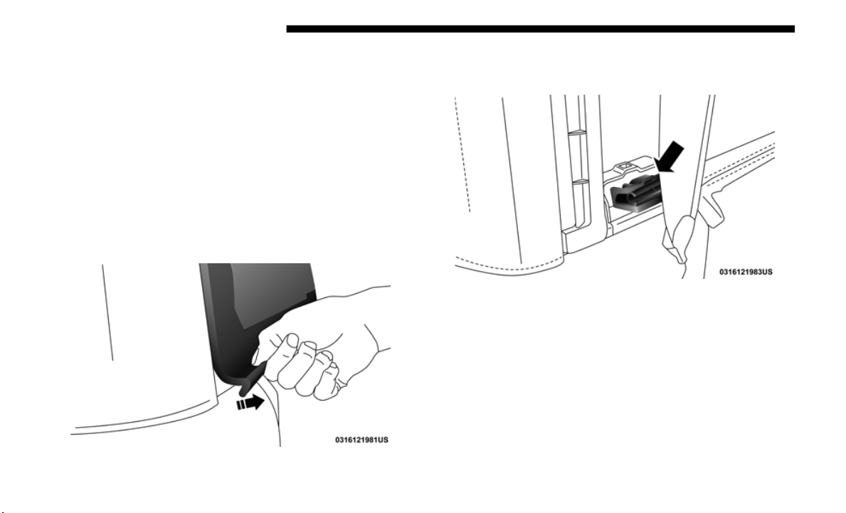
140 GETTING TO KNOW YOUR VEHICLE
NOTE:
The rear window and rear quarter windows must be rem
oved
before lowering the soft top to prevent damage to the top. Clean
side and rear windows before removal to assist in preventing
scratching during removal of the soft top. If the plastic retainers
are difficult to operate due to road dust, etc., clean them with a
mild soap solution and a small brush. Cleaning products are
available through your authorized dealer.
Remove The Rear Window:
1. With the swing gate open, remove the rear window’s
plastic
retainers from the lower right and left corners.
Step One
2. G
rasp the swing gate bar, rotate it outward and upward
releasi
ng it from both the right and left retainers.
Step Two (Left Side Shown)
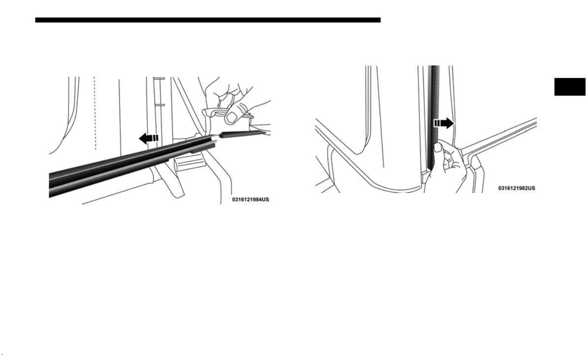
GETTING TO KNOW YOUR VEHICLE 141
3. While holding the window in place, slide the tailgate bar
to the left separating it from the rear window. Store in soft
window bag, or a safe location.
Step Three
4. Remove the plastic retainers from both quarter window
pillars.
Step Four
2
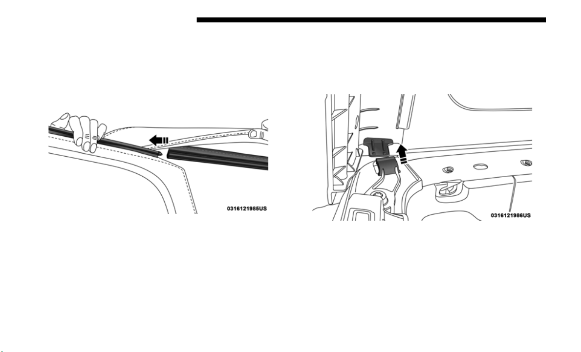
142 GETTING TO KNOW YOUR VEHICLE
5. While keeping the rear window level, slide to the left
until it is completely separate from its retainer. Do not
pull downward while removing the rear window.
Damage to the retainer could result.
Step Five
Remove The Right And Left Quarter Windows:
1. Through the rear opening, push the bottom corner
outward
and release tab from the bottom of the window
pillar.
Step One
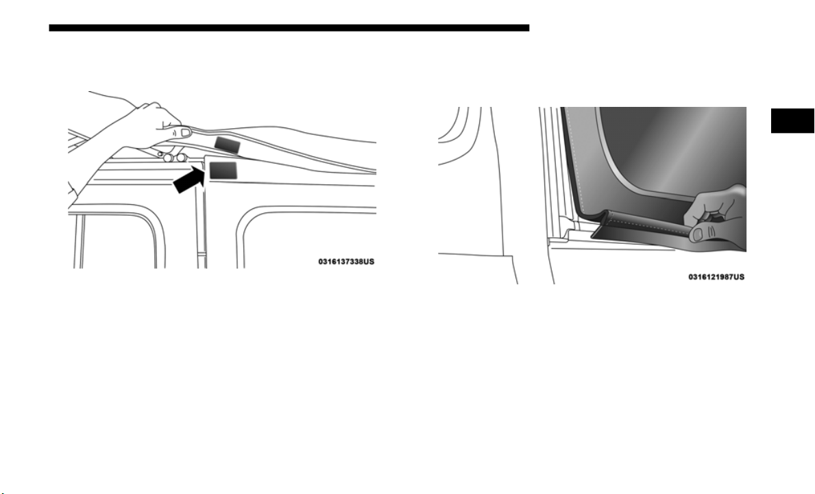
GETTING TO KNOW YOUR VEHICLE 143
2. Undo the hook-and-loop fastener located at the upper
front corner of each quarter window.
Hook-And-Loop Fastener Location
3. Starting at the rear of the vehicle, remove plastic retainer
from along the bottom of the window moving toward the
front of the vehicle.
Step Three
2
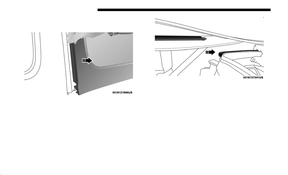
144 GETTING TO KNOW YOUR VEHICLE
4. Remove plastic retainer from the bottom to the top of the
front window.
Step Four
5. While keeping the window level, slide rearward until it is
complet
ely separate from its retainer. Do not pull down-
ward while removing the window. Damage to the
r
etainer
could result.
Step Five
6. Store in soft window bag or a safe location.
NOTE:
Ref
er to “Soft Top Window Storage Bag” in this section for
i
nformat
ion on the use of the storage bag.
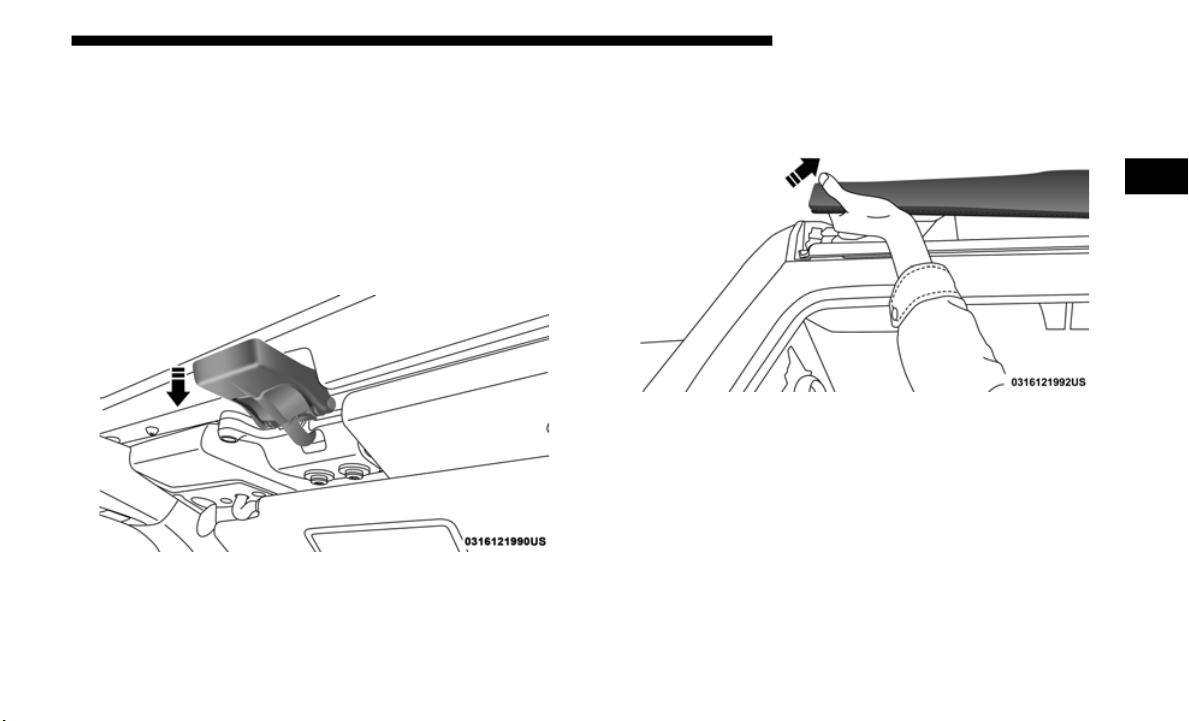
GETTING TO KNOW YOUR VEHICLE 145
Lowering The Soft Top Into Sunrider Position
1. After removing the rear window and quarter panel
windows,
move to the front of the vehicle.
2. Fo
ld both sun visors forward against the windshield.
3
. Relea
se the header latches from the crossbar by pulling
the han
dle downward. Make sure the hook is disengaged
from its receiver.
Step Three
4. From both the left and right sides, lift up on the #1 Bow
of the
soft top to start the operation.
Step Four
2
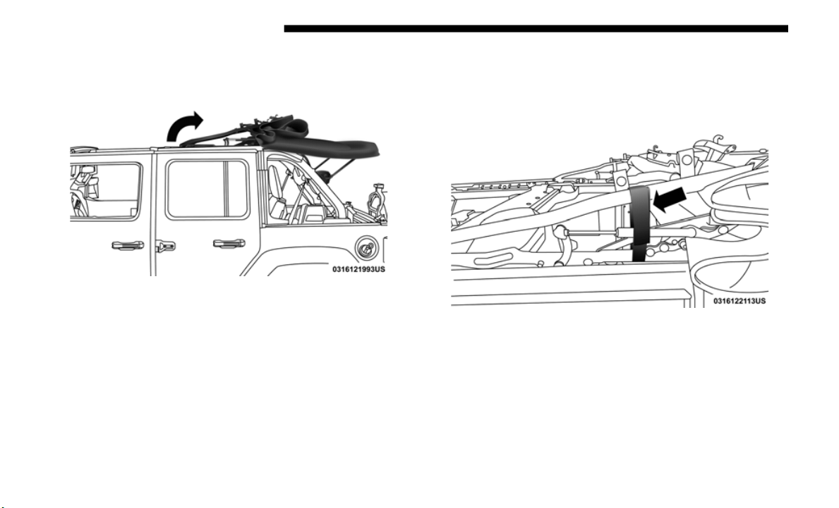
146 GETTING TO KNOW YOUR VEHICLE
5. Move to the side of the vehicle and use the side link to
fold the soft top rearward into the Sunrider position.
Step Five
NOTE:
If leaving the soft top in the Sunrider position, secure the top
by using t
he two hook-and-loop fasteners provided in the
center console.
Secured Top When In Sunrider Position
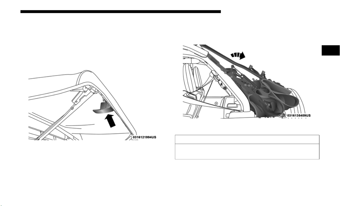
GETTING TO KNOW YOUR VEHICLE 147
Lowering The Soft Top Into Fully Lowered Position
1. From the Sunrider position, remove straps if previously
secured
and move to the rear of the vehicle.
2. L
ocate the Sunrider latch beneath the #6 Bow of the soft
t
op on
the left side.
Sunrider Latch Beneath #6 Bow
3. P
ull the latch to release the top, and allow the soft top to
slide r
earward freely in the guide tracks to the stowed
position.
Step Three
CAUTION!
Failure to follow the next steps could result in damage to
the Soft
Top or vehicle.
2
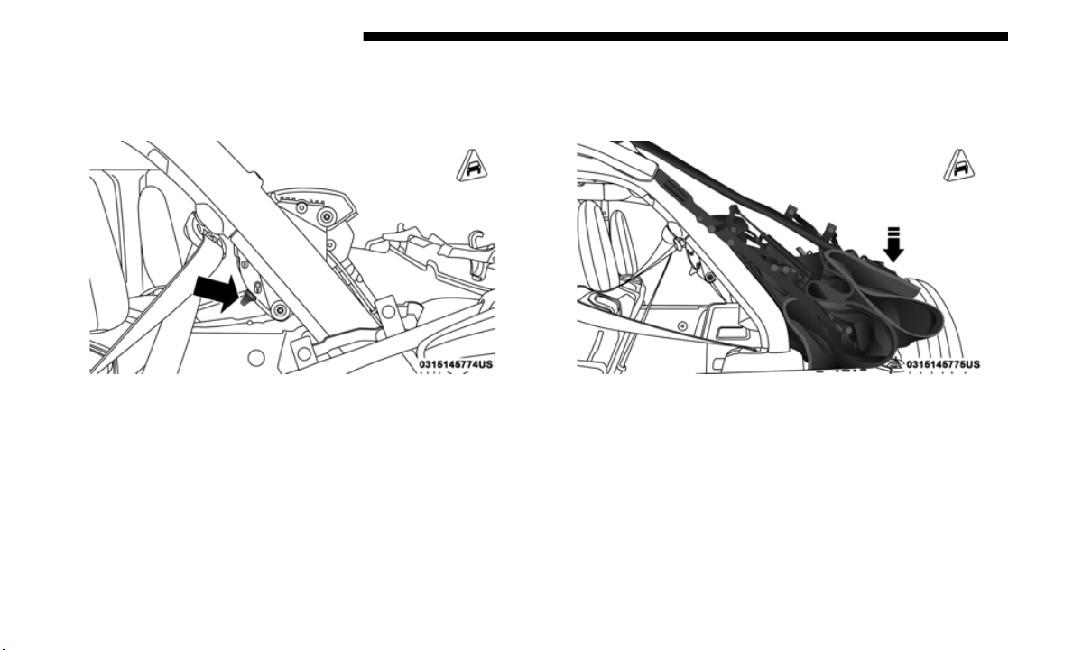
148 GETTING TO KNOW YOUR VEHICLE
4. While pushing downward slightly on the folded soft top,
slide the lock lever on the left and right side lift assist
mechanisms to the “lock” position.
Step Four (Locked Position)
5. Once the lock is in the “lock” position, push downward
on each side of the folded soft top to ensure it is secure.
An audible “click” may be heard.
Step Five
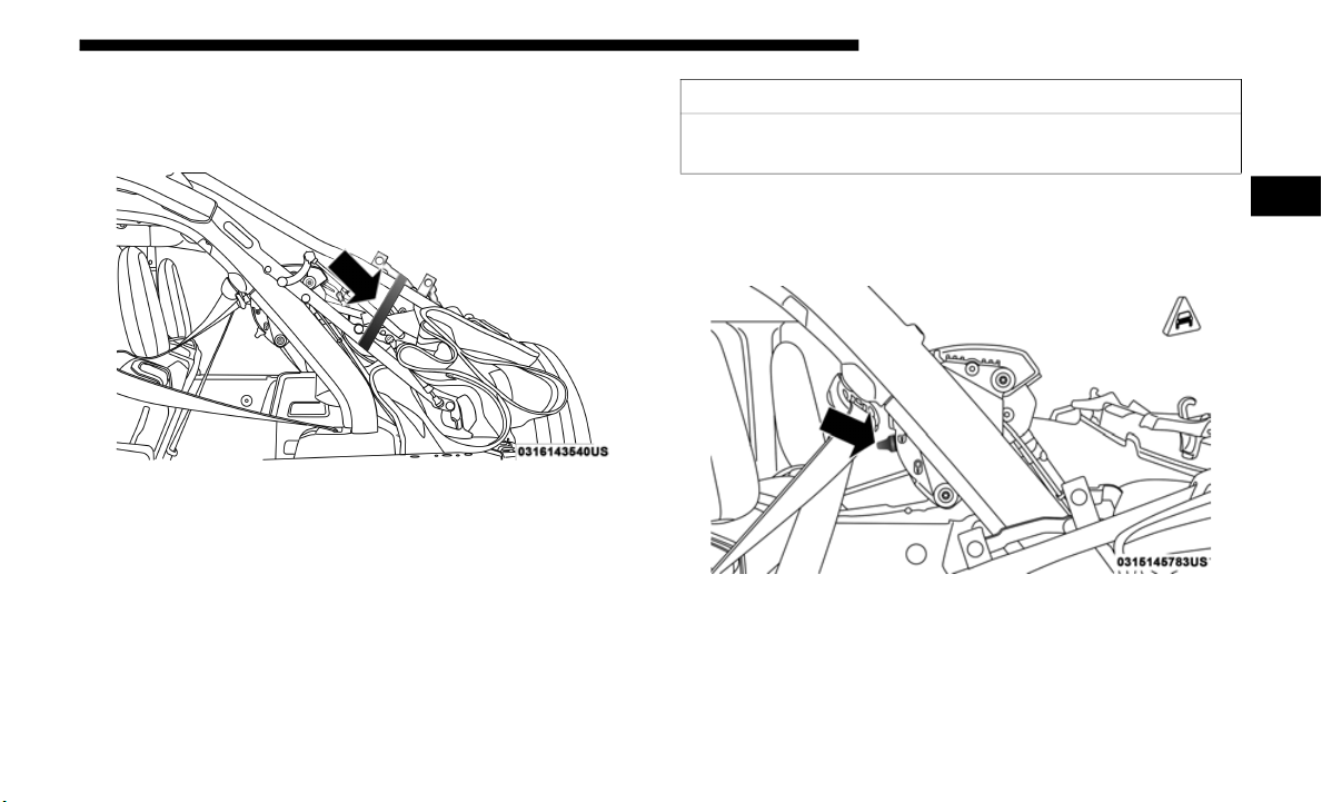
GETTING TO KNOW YOUR VEHICLE 149
NOTE:
Secure the top by using the two hook-and-loop fasteners
provided
in the center console.
Secured Top When In Fully Lowered Position
Raising The Soft Top
Raising The Soft Top From The Fully Lowered Position
1. From the fully lowered position, remove straps if previ-
ously se
cured.
2. W
hile pushing down on the rear of the top, slide the lock
lever o
n the left and right side Lift Assist Mechanisms to
the “unlock” position.
Unlocked Lift Assist Mechanism
CAUTION!
Failure to follow the next steps could result in damage to
the Soft
Top or vehicle.
2
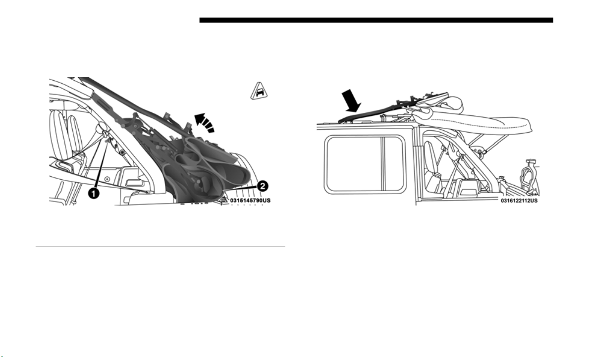
150 GETTING TO KNOW YOUR VEHICLE
3. Push up and forward from the #5 Bow along the guide
track until it locks into the Sunrider position with an
audible “click”.
Step Three
4. Gently pull rearward on the #6 Bow to ensure the top is
locked i
n the Sunrider position.
5. Using the side link, lift and push the soft top toward the
front o
f the vehicle manually guiding the top into the
closed position.
Lift From Side Link
1 — Unlocked Position
2 — #5 Bow Location
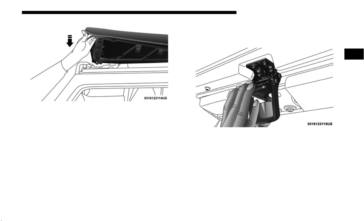
GETTING TO KNOW YOUR VEHICLE 151
Lower Top Into Closed Position
6. From inside the vehicle, pull the handle on the header
latch d
ownward to engage the hook into its receiver.
Repeat on the other side.
Step Six
2
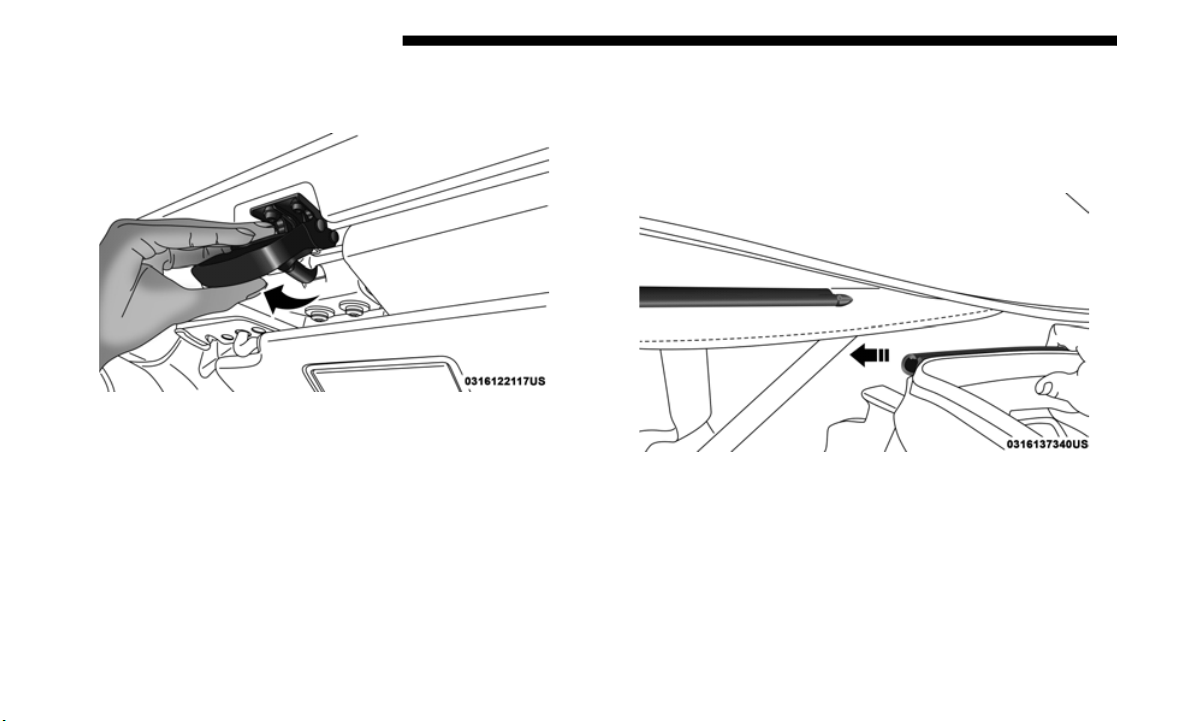
152 GETTING TO KNOW YOUR VEHICLE
7. Pull the handle back upward while squeezing the hook,
locking the latch into place.
Step Seven
Install The Right And Left Quarter Windows
1. From the rear of the vehicle, guide the top of the window
into th
e retainer and slide forward while keeping the
window level. Repeat on the other side.
Step One

GETTING TO KNOW YOUR VEHICLE 153
2. Place the top of the quarter window pillar into the top
cover, and insert the bottom tab into the clip.
Step Two
Step Two
CAUTION!
Failure to follow all Quarter Window Install steps could
result i
n damage to the Soft Top or vehicle.
2
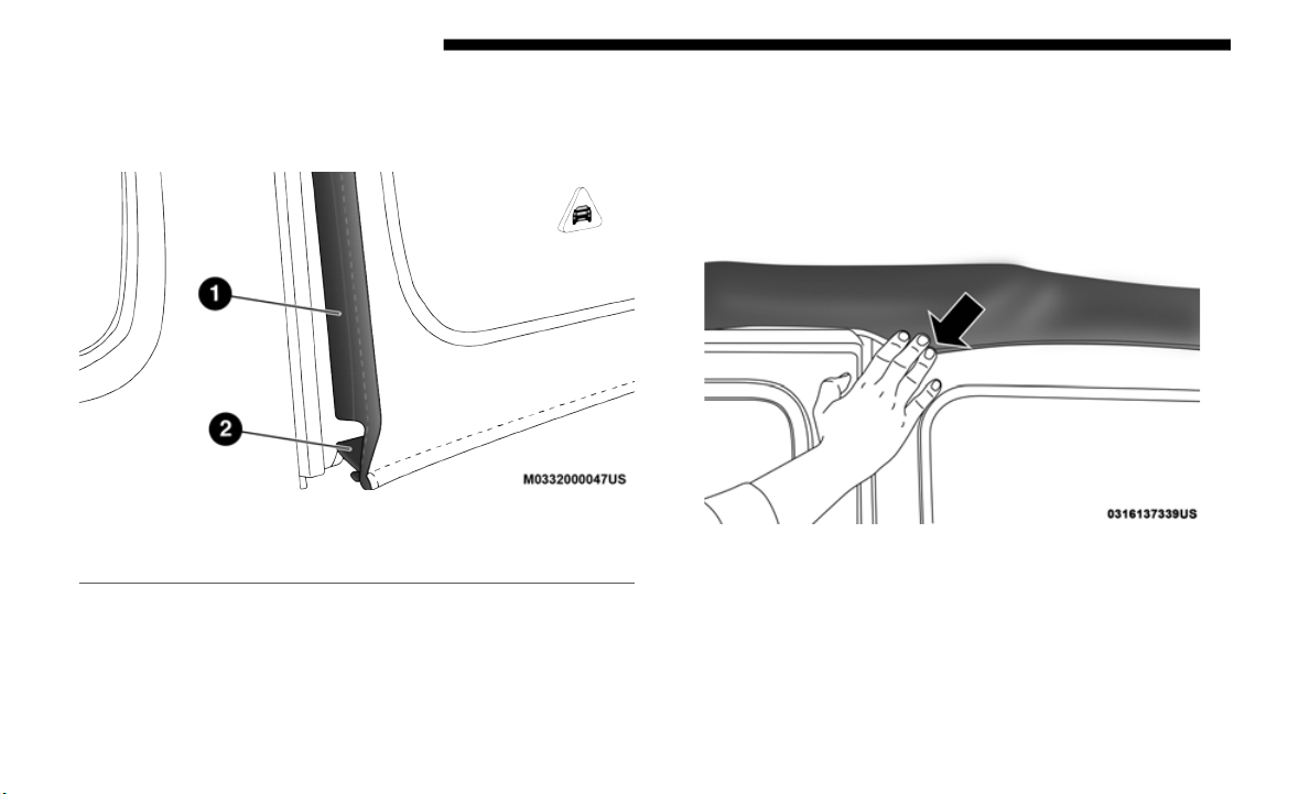
154 GETTING TO KNOW YOUR VEHICLE
3. Engage the retainers on the front of the windows,
ensuring they are fully engaged, followed by the retainers
along the bottom of the windows.
Fully Engage Quarter Window Retainers
NOTE:
It is critical that t
he retainers are fully engaged before the
vehicle resumes motion.
4. Secure the hook-and-loop fastener at the upper front
corner
of each quarter window by pressing firmly.
Firmly Secure Hook-And-Loop Fastener
1 — Retainer At Front Of Quarter Window
2 — Retainer At Bottom Of Quarter Window
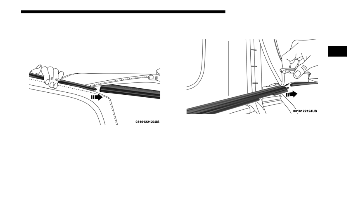
GETTING TO KNOW YOUR VEHICLE 155
Install The Rear Window
1. Guide the rear window into the retainer from left to right
while kee
ping the window level.
Step One
2. Insert the tailgate bar into the retainers at the bottom of
the wind
ow from left to the right.
Step Two
2
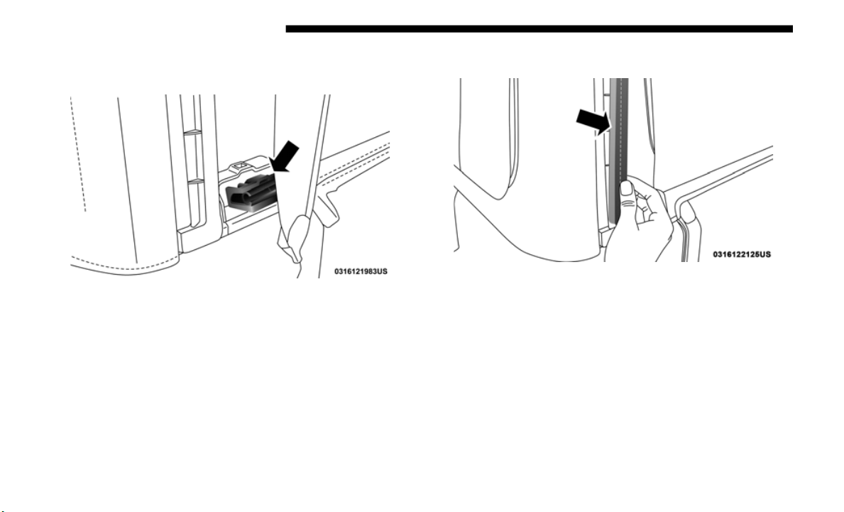
156 GETTING TO KNOW YOUR VEHICLE
3. Rotate the swing gate bar into the left and right side
retainers.
Step Three
4. Line up the rear window to the right si
de quarter
window first, and engage the plastic retainers.
5. Repeat with the left side quarter window.
Step Five
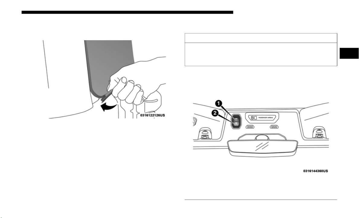
GETTING TO KNOW YOUR VEHICLE 157
6. Engage the rear window retainers in the lower right and
left corners.
Step Six
NOTE:
For information on removing your soft top, refer to
“Removin
g The Soft Top — Four Door Models” in “Getting
To Know Your Vehicle”.
POWER SLIDING TOP — IF EQUIPPED
If your vehicle is equipped with a Power Sliding Top, the
control switch can be found on the front trim panel, to the
right of the driver’s side sun visor.
Power Sliding Top Control Switch
CAUTION!
Lowering of the windshield is NOT recommended in
vehicles
equipped with a Power Sliding Top. Damage
will occur to the top as well as the header seal.
1 — Open Switch
2 — Close Switch
2

158 GETTING TO KNOW YOUR VEHICLE
NOTE:
• The Power Top is non-removable. If desired, the rear
quarte
r windows can be removed and stored in provided
storage bags. Refer to “Quarter Window Removal” in this
section for further information.
• The Power Top will not open in temperatures below –4°F
(-20°C
). However, if it is opened at a higher temperature, it
can be closed at temperatures above –40°F (-40°C).
• The Power Top will not operate at vehicle speeds above
60 mph
(96 km/h).
NOTE:
A slight pause in audio may be heard when opening and
c
losing
the Power Sliding Top as a result of the Uconnect
system switching between Power Top Closed and Power
Top Open audio modes.
WARNING!
• Never leave children unattended in a vehicle, or with
access
to an unlocked vehicle. Never leave the key fob
in or near the vehicle, or in a location accessible to chil
-
dren. Do not leave the ignition of a vehicle equipped
with Ke
yless Enter-N-Go in the ACC or ON/RUN
mode. Occupants, particularly unattended children,
can become entrapped by the power top while oper
-
ating the power top switch. Such entrapment may
r
esult
in serious injury or death.
• In a collision, there is a greater risk of being thrown
from a
vehicle with an open power top. You could also
be seriously injured or killed. Always fasten your seat
belt properly and make sure all passengers are also
properly secured.
• Do not allow small children to operate the power top.
Never a
llow your fingers, other body parts, or any
object, to project through the power top opening.
Injury may result.

GETTING TO KNOW YOUR VEHICLE 159
Opening The Power Top
Express Mode
Push the open switch and release it within one-half second.
The powe
r top will open automatically to the open position.
This is called “Express Open”. During Express Open opera
-
tion, any movement of the switch will stop the power top.
Manual Mode
To open the power top manually, push and hold the open
switch.
The power top will stop automatically at the open
position. Any release of the switch will stop the movement.
The power top will remain in a partially opened position
until the switch is pushed and held again.
Closing The Power Top
Express Mode
Push the close switch and release it within one-half second.
The power top will close fully and stop automatically. This is
called “Express Close”. During Express Close operation, any
movement of the switch will stop the power top.
Manual Mode
To close the power top manually, push and hold the close
switch.
The power top will move forward and automatically
stop at the fully closed position. Any release of the switch
will stop the movement. The power top will remain in a
partially closed position until the switch is pushed and held
again.
Wind Buffeting
Wind buffeting can be described as the perception of pres-
sure on the ears or a helicopter-type sound in the ears. Your
vehicle
may exhibit wind buffeting with the windows down,
or the power top in certain open or partially open positions.
This is a normal occurrence and can be minimized. If the
buffeting occurs with the rear windows open, then open the
front and rear windows together to minimize the buffeting.
If the buffeting occurs with the power top open, adjust the
power top opening to minimize the buffeting or open any
window.
2

160 GETTING TO KNOW YOUR VEHICLE
Pinch Protect Feature
This feature will detect an obstruction in the opening of the
power top during Express Close operation. If an obstruction
in the path of the power top is detected, the power top will
automatically retract. Remove the obstruction if this occurs.
Next, push the close switch and release to Express Close.
NOTE:
• T
he Power Sliding Top may reverse motion if closing
during
a severe headwind. If this occurs, push the Power
Sliding Top switch again to close the top completely.
• If three consecutive power top close attempts result in
Pinch
Protect reversals, Pinch Protect will disable and the
power top must be closed in Manual Mode.
Power Top Maintenance
Use only a non-abrasive cleaner and a soft cloth to clean the
quarter window glass panel.
Refer to “Bodywork” in Servicing And Maintenance” for
further
information. It contains important information on
cleaning and caring for your vehicle.
Ignition Off Operation
The power top switch can remain active in Accessory Delay
for up to approximately 10 minutes after the vehicle’s igni-
tion is placed to the Off position. Opening either front door
wi
ll can
cel this feature.
NOTE:
Ignition Off time is programmable through the Uconnect
S
ystem.
Refer to “Uconnect Settings/Customer Program-
mable Features” in “Multimedia” for further information.
WARNING!
There is no anti-pinch protection when the power top is
almost c
losed. To avoid personal injury be sure to clear
your arms, hands, fingers and all objects from the top’s
path before closing.

GETTING TO KNOW YOUR VEHICLE 161
Relearn Procedure
For vehicles equipped with a power top, there is a relearn
procedure that allows you to calibrate the power top when
the “Express Mode” stops working. To reset the power top,
follow these steps:
1. Place the ignition in the RUN position, and start the
vehicl
e.
NOTE:
The engine must be running to perform the relearn proce-
dure.
2. E
nsure the power top is in the fully closed position.
3. Push
and hold the Close switch for 10 seconds. This will
put th
e power top into calibration mode.
4. Continue holding down the close button while the top
goes fu
lly open and then back to fully close.
5. Once the power top has stopped in the fully closed posi-
tion,
release the close button. The power top is now reset
and rea
dy to use.
NOTE:
If the close button is released anytime during the relearning
p
rocess
, the relearn may not be complete, and the procedure
must be repeated.
Rear Quarter Window Removal
On vehicles equipped with a Power Sliding Top, the rear
quarter windows can be removed. To remove these
windows, follow the procedure below:
1. Open the swing gate, and lift the rear window.
2. Open
both side doors nearest the quarter windows.
3. Loca
te the rear quarter window latches (two on each
window)
on the interior of the windows.
4. Rotate the left hand side latch clockwi
se to release.
2
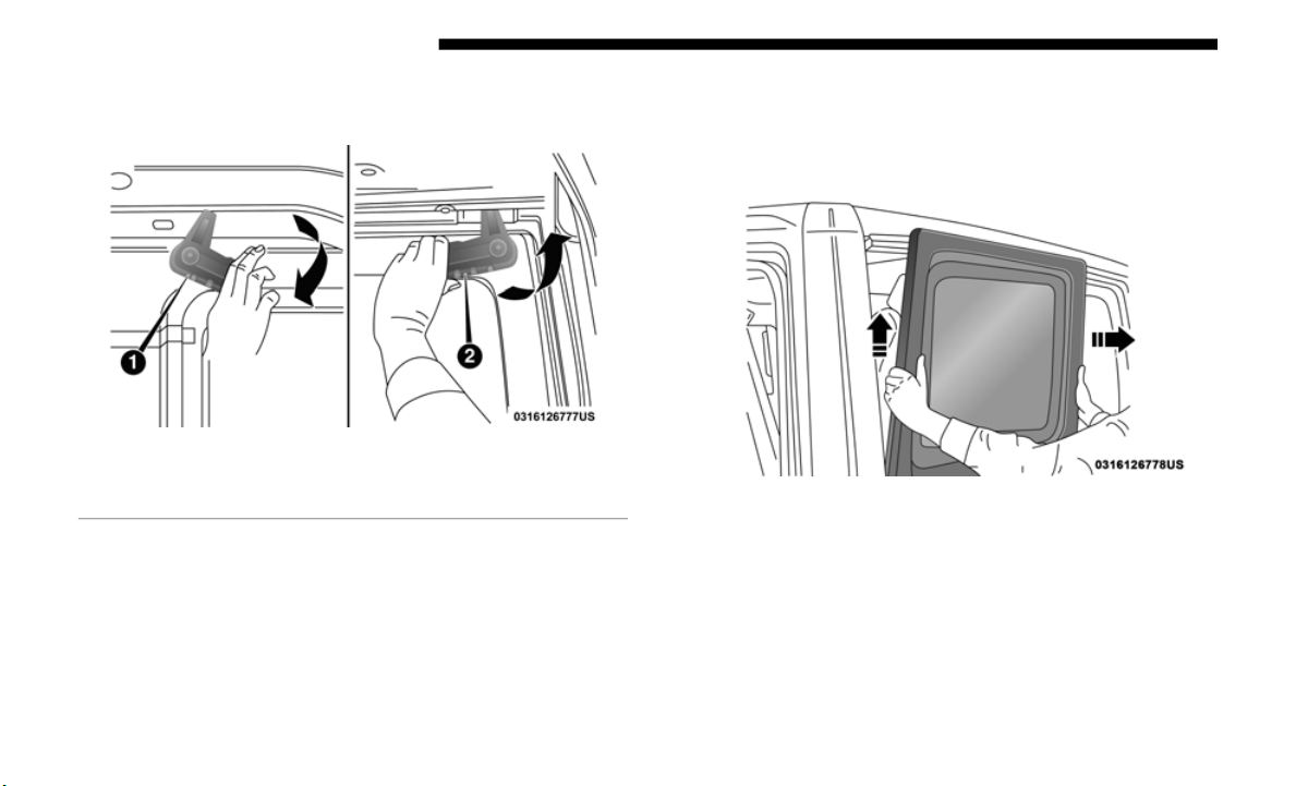
162 GETTING TO KNOW YOUR VEHICLE
5. Rotate the right hand side latch counterclockwise to
release.
Rear Quarter Window Release Latches
6. Fr
om the outside of the vehicle, lift each window upward
and away
from the vehicle.
NOTE:
Do not pull down or apply any weight to the windows after
the latc
hes are released. Damage could result to the pins
holding the windows in place.
Lift Quarter Window Upward And Outward
1 — Rotate Left Handle Clockwise
2 — Rotate Right Handle Counterclockwise
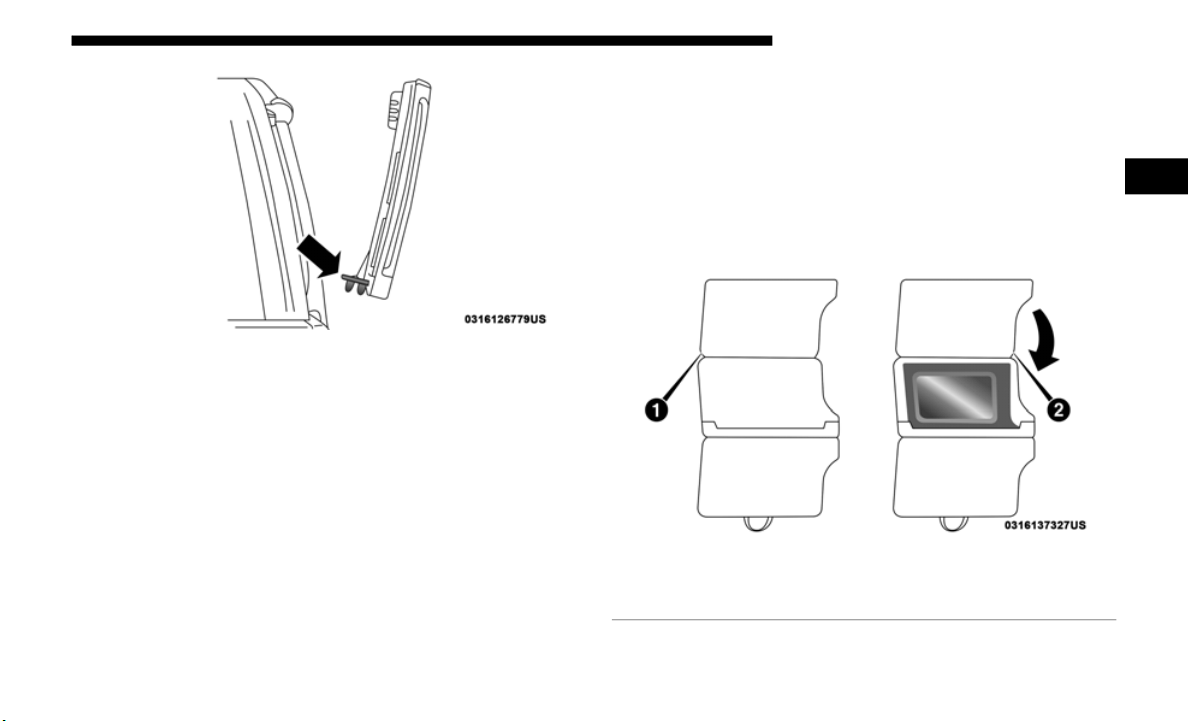
GETTING TO KNOW YOUR VEHICLE 163
Quarter Window Pins Location
7. Store the rear quarter windows in the provided storage
bag and
keep in a safe location, or securely fasten the bag
to the rear seat.
Quarter Window Storage Bag
To use the storage bags for the rear quarter windows,
proceed
as follows:
1. W
ith the bag completely open and the fabric divider
r
aised,
place the first quarter window with the latches
facing outward into the foam insert. Fold divider over the
window once placed inside.
Step One
1 — Bag Open With Divider Raised
2 — Lower Divider Over Window (Latches Facing Outward)
2
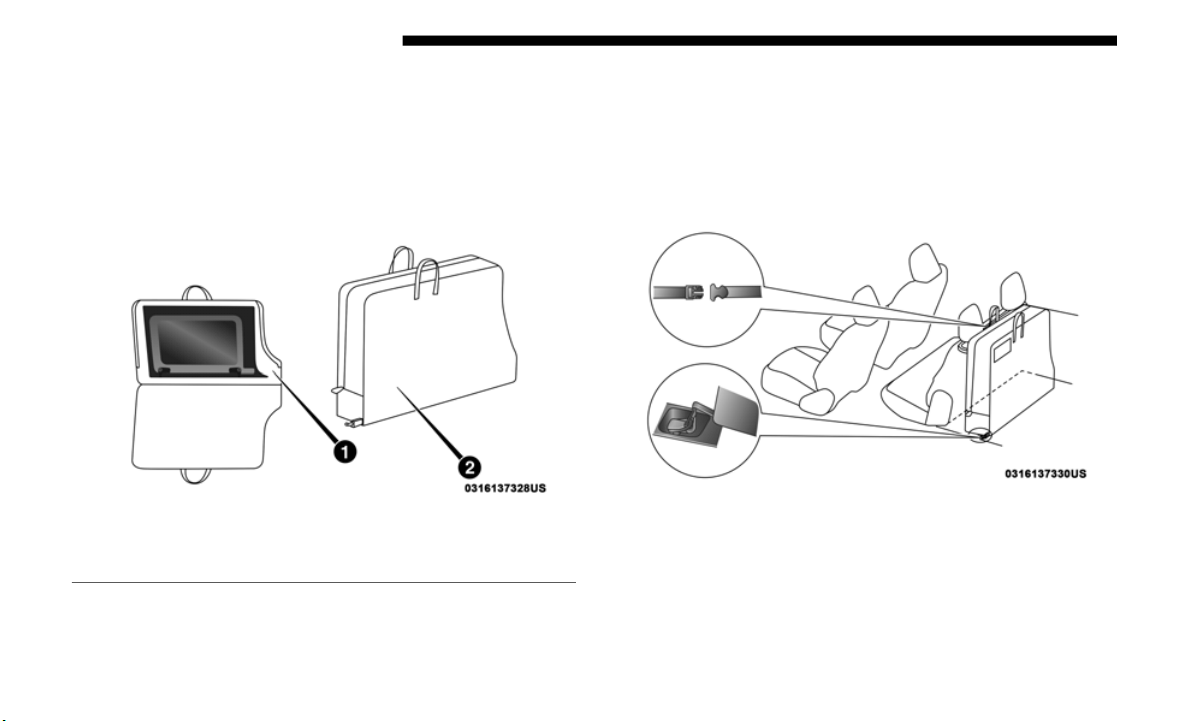
164 GETTING TO KNOW YOUR VEHICLE
2. Place the second window into the foam insert with the
latches facing outward. Fully close the bag.
NOTE:
Once both windows are placed inside the bag, the outside of
the windo
ws will be facing each other with all latches facing
the outside of the bag.
Step Two
3. Store the bag in a safe location, or in the cargo area of the
vehicle
by securing the bag in the vehicle’s cargo area.
This is done by attaching the straps at the top of the bag
to the rear head restraints, as well as attaching the clips at
the bottom of the bag to the forward most cargo hooks on
the load floor.
Step Three
1 — Second Window Placed Over Divider
2 — Fully Closed Bag

GETTING TO KNOW YOUR VEHICLE 165
(Continued)
FOLDING WINDSHIELD
The fold-down windshield on your vehicle is a structural
element that can provide some protection in some accidents.
The windshield also provides some protection against
weather, road debris and intrusion of small branches and
other objects.
Do not drive your vehicle on-road with the windshield
down, as
you lose the protection this structural element can
provide.
If required for certain off-road uses, the windshield can be
folded
down. However, the protection afforded by the wind-
shield is then lost. If you fold down the windshield, drive
s
lowly an
d cautiously. It is recommended that the speed of
the vehicle be limited to 10
mph (16 km/h), with low range
operati
on preferred if you are driving off-road with the
windshield folded down.
Raise the windshield as soon as the task that required its
removal
is completed and before you return to on-road
driving. Both you and your passengers should wear seat
belts at all times, on-road and off-road, regardless of whether
the windshield is raised or folded down.
Outside rearview mirrors are mounted on the doors. If you
choose
to remove the doors, see an authorized dealer for a
replacement cowl-mounted outside mirror. Federal law
requires outside mirrors on vehicles for on-road use.
CAUTION!
Lowering of the windshield is NOT recommended in
vehicles
equipped with a Power Sliding Top. Damage
will occur to the top as well as the header seal.
WARNING!
• Do not drive your vehicle on-road with the windshield
down.
• Do
not drive your vehicle unless the windshield is
secure
ly fastened, either up or down.
• Eye protection, such as goggles, should be worn at all
times
when the windshield is down.
• Be sure that you carefully follow the instructions for
raisin
g the windshield. Make sure that the folding
windshield, windshield wipers, side bars, and all asso
-
ciated hardware and fasteners are correctly and tightly
assembl
ed before driving your vehicle. Failure to
follow these instructions may prevent your vehicle
from providing you and your passengers’ protection in
some accidents.
2
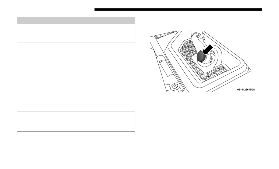
166 GETTING TO KNOW YOUR VEHICLE
Lowering The Windshield
1. Before completing the steps below:
• If your vehicle is equipped with a Soft Top, the top
MUST be
lowered, and the door rails must be removed
prior to lowering the windshield.
• If your vehicle is equipped with a Hard Top, the
Freedom
Panels MUST be removed prior to lowering
the windshield.
• Refer to the “Soft Top,” “Door Frame,” and “Freedom
Top” in
structions in this section for more information.
2. Manually remove the protective caps over the windshield
wiper he
x bolts.
Protective Cap Over Wiper Bolt
3. Using the provided 15mm socket, remove the two hex
bolts a
nd remove the wiper arms.
4. Move to the inside of the vehicle and lower both sun
visors.
•
If you remove the doors, store them outside the vehicle.
In the
event of an accident, a loose door may cause
personal injury.
CAUTION!
Failure to follow this step will cause damage to the
vehicle’s
header seal.
WARNING! (Continued)

GETTING TO KNOW YOUR VEHICLE 167
5. Using the provided #40 Torx head driver, remove the
four Torx screws located along the interior of the wind-
shield.
Interior Torx Screw Locations
NOTE:
Store all of the mounting bolts in their original threaded
h
oles an
d tighten for safekeeping.
6. Lower the windshield gently until it contacts the footman
loop bu
mpers (if equipped).
Footman Loop Bumpers
7. Secure the windshield by passing a cinch strap through
the foo
tman loops on either side of the hood and on the
windshield frame. Tighten the strap to secure the wind
-
shield in place.
1 — Bumper
2 — Footman Loop
3 — Washer Nozzle
CAUTION!
Do Not Overtighten! Damage to the windshield could result.
2
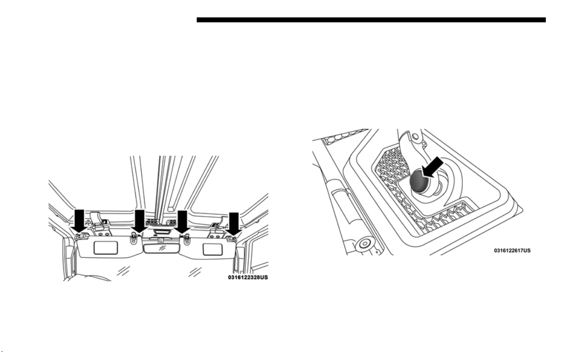
168 GETTING TO KNOW YOUR VEHICLE
Raising The Windshield
1. Release the strap that secured the windshield in the
lowered position.
2. Raise the windshield.
3. Using
the provided #40 Torx h
ead driver, reinstall the
four Torx screws located along the interior of the wind-
shield. Secure them until they are snug, being careful not
t
o cross
-thread the screws or overtighten.
Interior Torx Screw Locations
4. Reinstall the windshield wiper arms using the provided
15 mm so
cket. First, align the tips of the blade to the “T”
mark in t
he glass. Then, while holding the arm in that
position, reinstall the hex nut and tighten until snug. Be
careful not to over-tighten. Repeat for the other arm.
5. Replace the protective caps over the wiper arm hex bolts
and pus
h gently until they snap into place.
Protective Cap Over Wiper Bolt
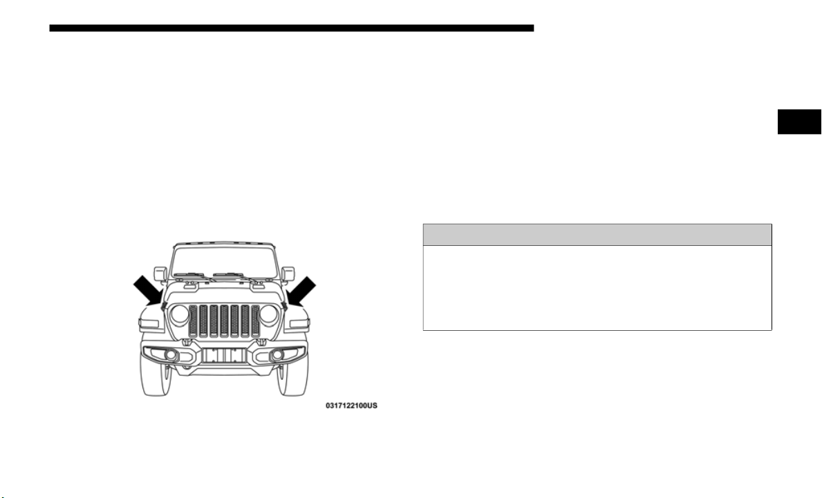
GETTING TO KNOW YOUR VEHICLE 169
6. After completing the steps above:
• If your vehicle is equipped with a Soft Top, reinstall the
Door Ra
ils and raise the top.
• If your vehicle is equipped with a Hard Top, reinstall
the Free
dom Panels.
HOOD
Opening The Hood
Release both the hood latches.
Hood Latch Locations
Raise the hood and locate the safety latch, located in the
middle o
f the hood opening. Push the safety latch to the left
side of the vehicle, to open the hood. You may have to push
down slightly on the hood before pushing the safety latch.
Insert the support rod into the slot on the hood.
Closing The Hood
To close the hood, remove the support rod from the hood
panel and place it in the retaining clip. Lower the hood
slowly. Secure both of the hood latches.
WARNING!
Be sure the hood is fully latched before driving your
vehicle.
If the hood is not fully latched, it could open
when the vehicle is in motion and block your vision.
Failure to follow this warning could result in serious
injury or death.
2
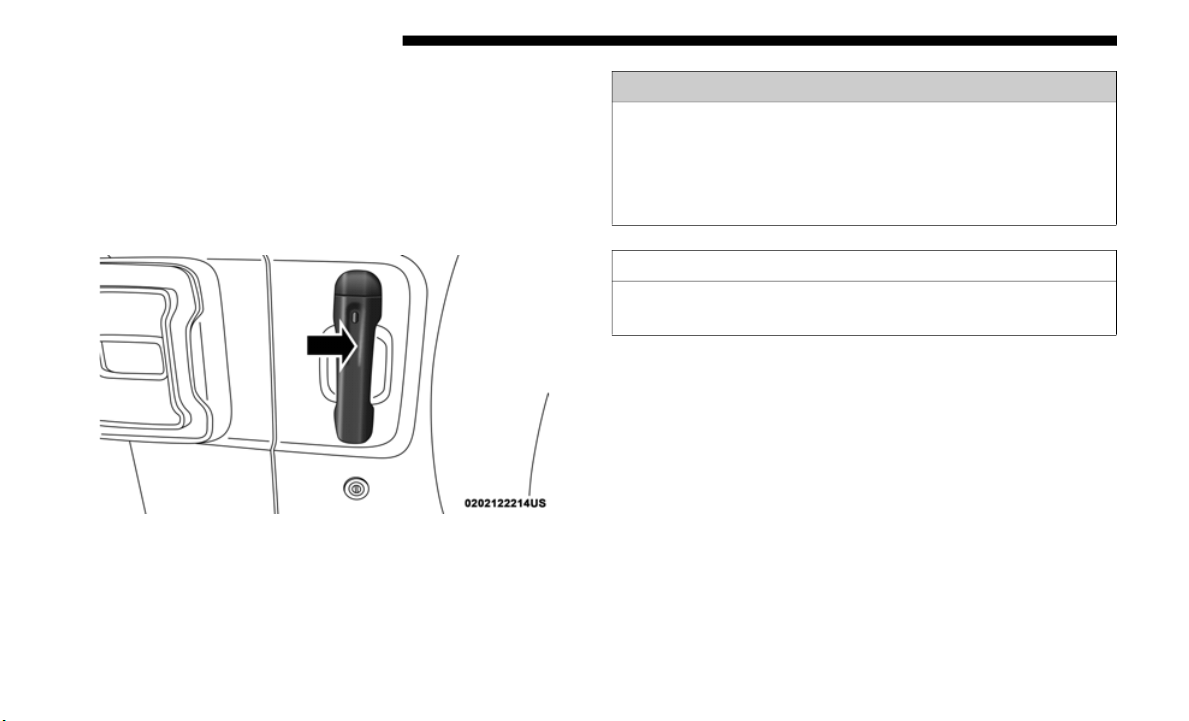
170 GETTING TO KNOW YOUR VEHICLE
REAR SWING GATE
The rear swing gate can be unlocked by using the key,
Remote Keyless Entry key fob, by activating the power door
lock switches located on the front doors, or grabbing the
handle if equipped with Keyless Enter-N-Go.
To open the swing gate, pull on the gate handle.
Swing Gate Handle
NOTE:
Close the rear flip-up window before attempting to close the
s
wing gate
(hard top models only).
NOTE:
The swing gate hinges and check strap may require cleaning
i
f a squ
eak can be heard when opening the swing gate. For
further information on vehicle cleaning procedures, refer to
“Interiors” in Servicing And Maintenance”.
WARNING!
Driving with the flip-up window open can allow
poisonous e
xhaust gases into your vehicle. You and your
passengers could be injured by these fumes. Keep the
flip-up window closed when you are operating the
vehicle.
CAUTION!
Do not push on rear wiper blade when closing the rear
flip-up window, as damage to the blade will result.
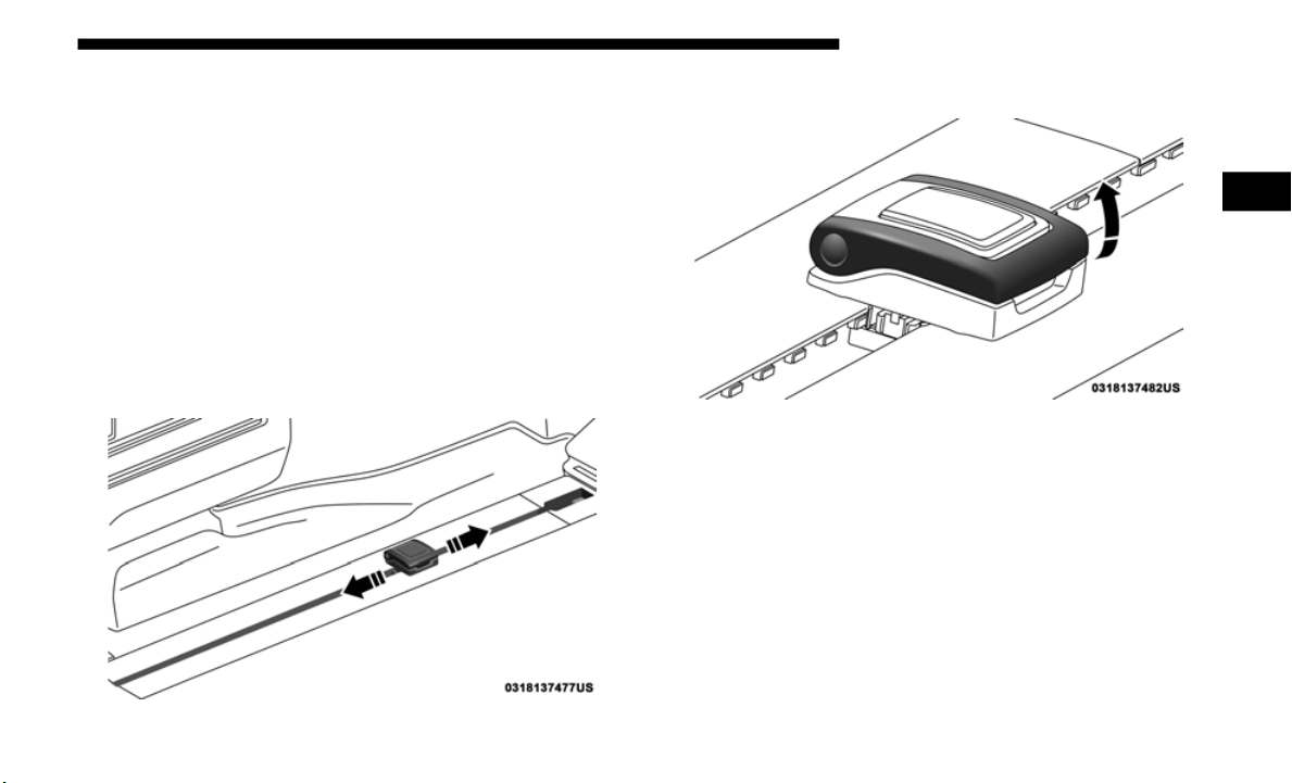
GETTING TO KNOW YOUR VEHICLE 171
Cargo Area Features
Trail Rail Cargo Organizer — If Equipped
If your vehicle is equipped with the Trail Rail system, a rail
will be f
ound built into the floor on either side of the cargo
area. Each rail contains an adjustable anchor loop that can be
used to secure cargo. The position of the adjustable anchor
loop can be adjusted by sliding the loop along the rail.
To adjust the anchor loop, push down on the center button
while sli
ding the loop along the rail to the desired position.
Release the button and move the loop slightly to the next
fixed position in the notches of the rail.
Adjustable Anchor Loop
Lift the loop to use.
Lift Adjustable Anchor Loop
GARAGE DOOR OPENER — IF EQUIPPED
HomeLink replaces up to three hand-held transmitters that
operate devices such as garage door openers, motorized
gates, lighting or home security systems. The HomeLink unit
is powered by your vehicle’s 12 Volt battery.
The HomeLink buttons, located on the sun visor or the over-
head console, designate the three different HomeLink chan-
nels. The HomeLink indicator is located above the center
b
utton.
2
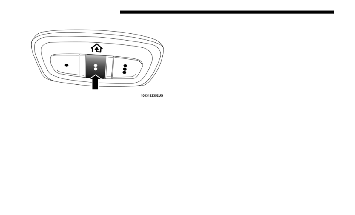
172 GETTING TO KNOW YOUR VEHICLE
HomeLink Buttons/Overhead Console
NOTE:
HomeLink is disabled when the Vehicle Security Alarm is
a
c
tive.
Before You Begin Programming HomeLink
Be sure that your vehicle is parked outside of the garage
before you begin programming.
For more efficient programming and accurate transmission
of the r
adio-frequency signal it is recommended that a new
battery be placed in the hand-held transmitter of the device
that is being programmed to the HomeLink system.
To erase the channels, place the ignition in the ON/RUN
position
, and push and hold the two outside HomeLink
buttons (I and III) for up to 20 seconds or until the orange
indicator flashes.
NOTE:
• E
rasing all channels should only be performed when
programm
ing HomeLink for the first time. Do not erase
channels when programming additional buttons.
• If you have any problems, or require assistance, please call
toll-fr
ee 1-800-355-3515 or, on the Internet at HomeLink.com
for information or assistance.
Programming A Rolling Code
For programming garage door openers that were manufac-
tured after 1995. These garage door openers can be identified
by the “L
EARN” or “TRAIN” button located where the
hanging antenna is attached to the garage door opener.
NOTE:
It is NOT the button that is normally used to open and close
the door
. The name and color of the button may vary by
manufacturer.
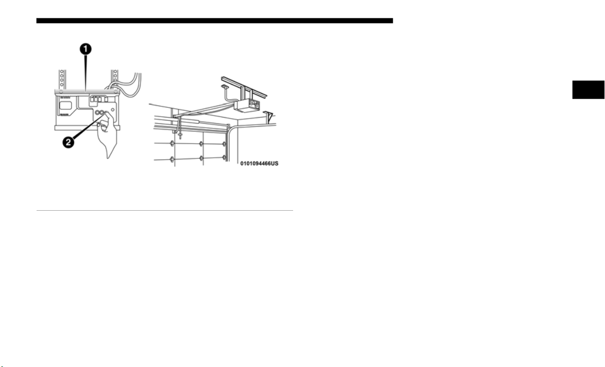
GETTING TO KNOW YOUR VEHICLE 173
Training The Garage Door Opener
1. Place the ignition in the ON/RUN position.
2. Plac
e the hand-held transmitter 1 to 3 inche
s (3 to 8 cm)
away from the HomeLink button you wish to program
while keeping the HomeLink indicator light in view.
3. Push and hold the HomeLink button you want to
program
while you push and hold the hand-held trans-
mitter button.
4. C
ontinue to hold both buttons and observe the indicator
light.
The HomeLink indicator will flash slowly and then
rapidly after HomeLink has received the frequency signal
from the hand-held transmitter. Release both buttons
after the indicator light changes from slow to rapid.
5. At the garage door opener motor (in the garage), locate
the “L
EARN” or “TRAINING” button. This can usually
be found where the hanging antenna wire is attached to
the garage door opener/device motor. Firmly push and
release the “LEARN” or “TRAINING” button. On some
garage door openers/devices there may be a light that
blinks when the garage door opener/device is in the
LEARN/TRAIN mode.
NOTE:
You have 30 seconds in which to initiate the next step after
the LEA
RN button has been pushed.
6. Return to the vehicle and push the programmed Home-
Link bu
tton twice (holding the button for two seconds
each ti
me). If the garage door opener/device activates,
programming is complete.
1 — Door Opener
2 — Training Button
2

174 GETTING TO KNOW YOUR VEHICLE
NOTE:
If the garage door opener/device does not activate, push the
button
a third time (for two seconds) to complete the
training.
To program the remaining two HomeLink buttons, repeat
each st
ep for each remaining button. DO NOT erase the
channels.
Reprogramming A Single HomeLink Button (Rolling
Code)
To r
eprogram a channel that has been previously trained,
follow t
hese steps:
1. Cycle the ignition to the ON/RUN position.
2. Push
and hold the desired HomeLink button until the
indica
tor light begins to flash after 20 seconds. Do not
release the button.
3. Without releasing the button proceed with “Program-
ming A
Rolling Code” step 2 and follow all remaining
steps."
P
rogramming A Non-Rolling Code
For programming Garage Door Openers manufactured
before
1995.
1. C
ycle the ignition to the ON/RUN position.
2
. Plac
e the hand-held transmitter 1 to 3 inche
s (3 to 8 cm)
away from the HomeLink button you wish to program
while keeping the HomeLink indicator light in view.
3. Press and hold the HomeLink button you want to
program
while you press and hold the hand-held trans-
mitter button.
4. C
ontinue to hold both buttons and observe the indicator
light.
The HomeLink indicator will flash slowly and then
rapidly after HomeLink has received the frequency signal
from the hand-held transmitter. Release both buttons
after the indicator light changes from slow to rapid.

GETTING TO KNOW YOUR VEHICLE 175
5. Press and hold the programmed HomeLink button and
observe the indicator light.
• If the indicator light stays on constantly, programming
is com
plete and the garage door/device should acti-
vate when the HomeLink button is pressed.
• T
o program the two remaining HomeLink buttons,
repeat
each step for each remaining button. DO NOT
erase the channels.
Reprogramming A Single HomeLink Button (Non-Rolling
Code)
To r
eprogram a channel that has been previously trained,
follow t
hese steps:
1. Cycle the ignition to the ON/RUN position.
2. Pres
s and hold the desired HomeLink button until the
indica
tor light begins to flash after 20 seconds. Do not
release the button.
3. Without releasing the button, proceed with “Program-
ming A
Non-Rolling Code” step 2 and follow all
remaini
ng steps.
Canadian/Gate Operator Programming
For programming transmitters in Canada/United States that
require the transmitter signals to “time-out” after several
seconds of transmission.
Canadian radio frequency laws require transmitter signals to
time-ou
t (or quit) after several seconds of transmission –
which may not be long enough for HomeLink to pick up the
signal during programming. Similar to this Canadian law,
some U.S. gate operators are designed to time-out in the
same manner.
It may be helpful to unplug the device during the cycling
process
to prevent possible overheating of the garage door or
gate motor.
1. Cycle the ignition to the ON/RUN position.
2. Plac
e the hand-held transmitter 1 to 3 inche
s (3 to 8 cm)
away from the HomeLink button you wish to program
while keeping the HomeLink indicator light in view.
2

176 GETTING TO KNOW YOUR VEHICLE
3. Continue to press and hold the HomeLink button, while
you press and release (“cycle”) your hand-held trans-
mitter every two seconds until HomeLink has success-
fully accepted the frequency signal. The indicator light
wi
ll fla
sh slowly and then rapidly when fully trained.
4. Watch for the HomeLink indicator to change flash
rates.
When it changes, it is programmed. It may take
up to 30 seconds or longer in rare cases. The garage
door may open and close while you are programming.
5. Press and hold the programmed HomeLink button and
observ
e the indicator light.
NOTE:
• If the indicator light stays on constantly, programming is
comple
te and the garage door/device should activate
when the HomeLink button is pressed.
• To program the two remaining HomeLink buttons, repeat
each s
tep for each remaining button. DO NOT erase the
channels.
If you unplugged the garage door opener/device for
programm
ing, plug it back in at this time.
Reprogramming A Single HomeLink Button (Canadian/
Gate Op
erator)
To reprogram a channel that has been previously trained,
follow t
hese steps:
1. Cycle the ignition to the ON/RUN position.
2. Pres
s and hold the desired HomeLink button until the
indica
tor light begins to flash after 20 seconds. Do not
release the button.
3. Without releasing the button, proceed with “Canadian/
Gate O
perator Programming” step 2 and follow all
remaining steps.
Using HomeLink
To operate, push and release the programmed HomeLink
button. Activation will now occur for the programmed
device (i.e. garage door opener, gate operator, security
system, entry door lock, home/office lighting, etc.). The
hand-held transmitter of the device may also be used at any
time.

GETTING TO KNOW YOUR VEHICLE 177
Security
It is advised to erase all channels before you sell or turn in
your vehicle.
To do this, push and hold the two outside buttons for 20 seconds
until t
he orange indicator flashes. Note that all channels will be
erased. Individual channels cannot be erased.
The HomeLink Universal Transceiver is disabled when the
Vehicle
Security Alarm is active.
NOTE:
The universal garage door opener only operates when the
e
ngine i
s running for security reasons associated with
removable tops and doors.
Troubleshooting Tips
If you are having trouble programming HomeLink, here are
some of the most common solutions:
• Replace the battery in the Garage Door Opener hand-held
transm
itter.
• Push the LEARN button on the Garage Door Opener to
comple
te the training for a Rolling Code.
• Did you unplug the device for programming and
rememb
er to plug it back in?
If you have any problems, or require assistance, please call
toll-fr
ee 1-800-355-3515 or, on the Internet at HomeLink.com
for information or assistance.
WARNING!
• Vehicle exhaust contains carbon monoxide, a
dangerou
s gas. Do not run your vehicle in the garage
while programming the transceiver. Exhaust gas can
cause serious injury or death.
• Your motorized door or gate will open and close while
you are
programming the universal transceiver. Do not
program the transceiver if people, pets or other objects
are in the path of the door or gate. Only use this trans
-
ceiver with a garage door opener that has a “stop and
r
everse”
feature as required by Federal safety stan-
dards. This includes most garage door opener models
m
anufac
tured after 1982. Do not use a garage door
opener without these safety features. Call toll-free
1-800-355-3515 or, on the Internet at
HomeLink.com for
safety information or assistance.
2
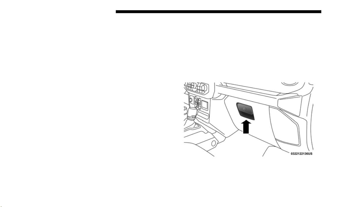
178 GETTING TO KNOW YOUR VEHICLE
General Information
The following regulatory statement applies to all Radio
Frequency (RF) devices equipped in this vehicle:
This device complies with Part 15 of the FCC Rules and with
Innovati
on, Science and Economic Development Canada
license-exempt RSS standard(s). Operation is subject to the
following two conditions:
1. This device may not cause harmful interference, and
2. This
device must accept any interference received,
includi
ng interference that may cause undesired opera-
tion.
NOTE:
Changes or modifications not expressly approved by the
p
arty res
ponsible for compliance could void the user’s
authority to operate the equipment.
INTERNAL EQUIPMENT
Storage
Glove Compartment
The glove compartment is located on the passenger side of
the inst
rument panel.
To open the glove compartment, pull the release handle.
Glove Compartment
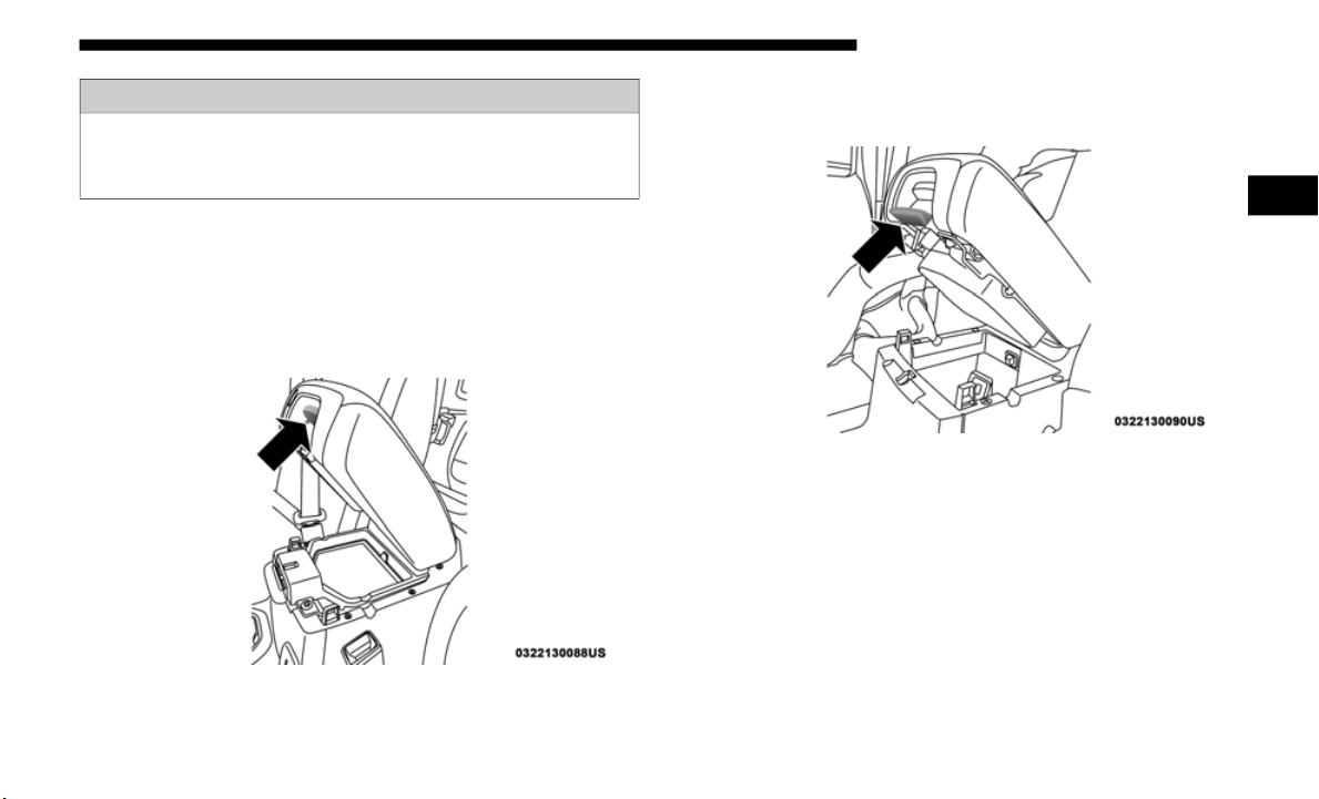
GETTING TO KNOW YOUR VEHICLE 179
Console Storage Compartment
The center console has both an upper and lower storage
compartment.
To open the upper storage compartment, lift the top latch.
Upper Console Storage Latch
To access the lower storage compartment, lift the bottom
latch.
Lowe
r Console Storage Latch
WARNING!
Do not operate this vehicle with a glove compartment in
the open
position. Driving with the glove compartment
open may result in injury in a collision.
2
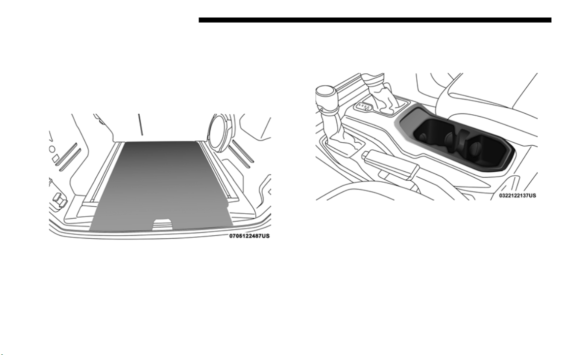
180 GETTING TO KNOW YOUR VEHICLE
Rear Storage Compartment — If Equipped
The rear cargo area storage compartment is located under-
neath the load floor.
To access the storage compartment, lift up on the cover
c
utout a
t the rear of the cargo area.
Rear Storage Cover
Cupholders
The front cupholders are located in the center console.
Front Cupholders
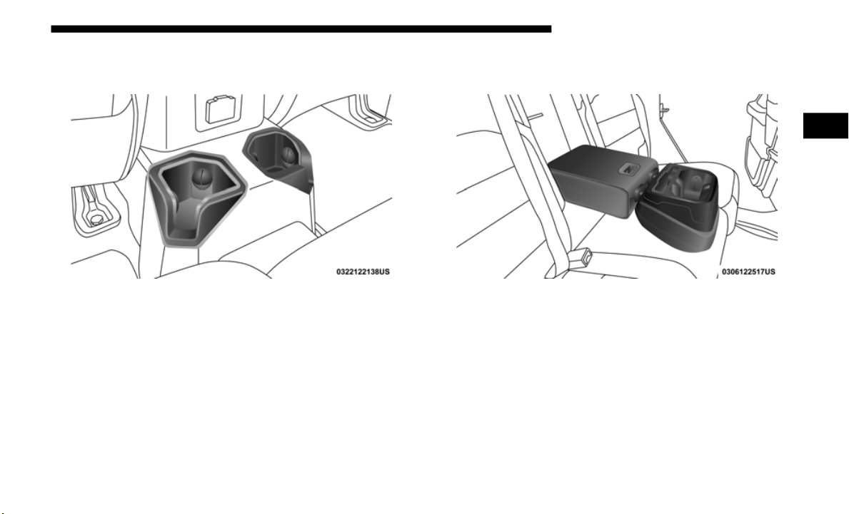
GETTING TO KNOW YOUR VEHICLE 181
The rear cupholders are located on the back of the center
console, near the floor.
Rear Cupholders
NOTE:
Cupholders located in the front center console, as well as the
b
ack of t
he center console are not removable.
There are also cupholders located in the rear seat armrest, if
equipped
. These cupholders can be removed for cleaning.
Rear Seat Armrest Cupholders
2

182 GETTING TO KNOW YOUR VEHICLE
Electrical Power Outlets
There are two 12 Volt (13 Amp) auxiliary power outlets that
can provide power for accessories designed for use with the
standard power outlet adapters.
The front power outlet is located in the center of the instru-
ment panel below the climate controls, and is powered from
the ignit
ion switch. Power is available when the ignition
switch is in the ON or ACC position.
Front Power Outlet
On vehicles equipped with a rear subwoofer, there is a
second p
ower outlet located in the rear cargo area and is
powered directly from the vehicle battery.
Rear Cargo Power Outlet
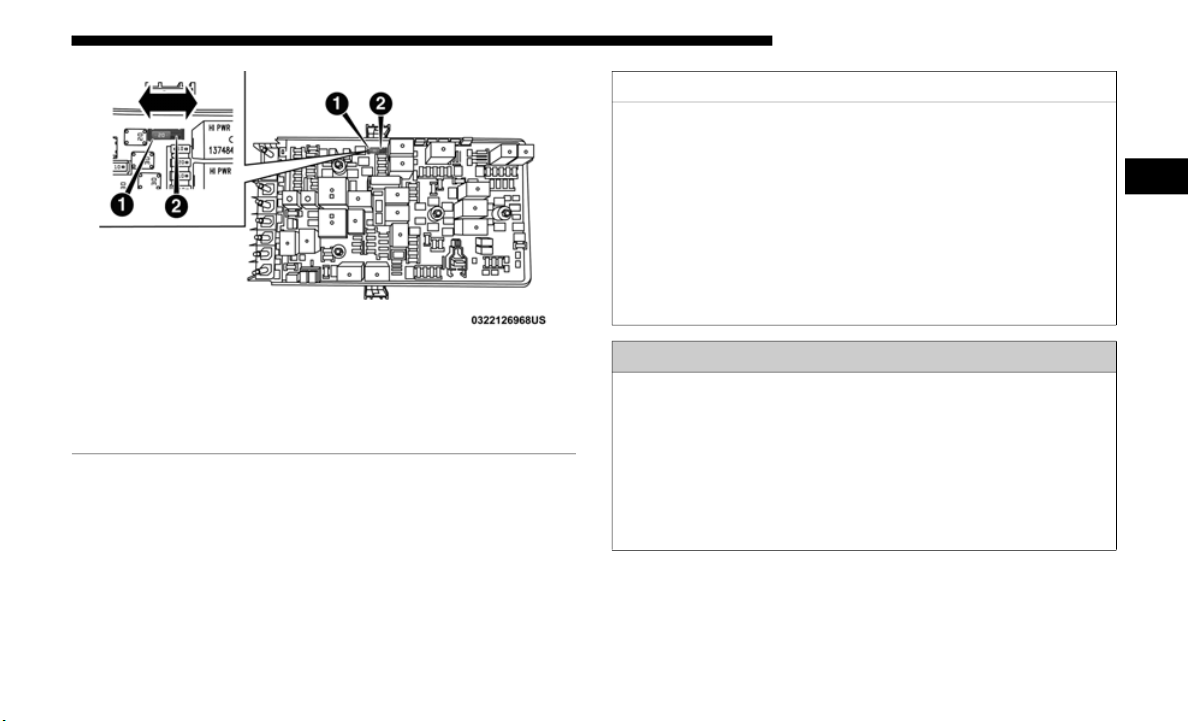
GETTING TO KNOW YOUR VEHICLE 183
Power Outlets Fuse Locations
1 — F81 Fuse 20A Yellow Rear Power Outlet (battery powered at all
times)
2 — F91 Fuse 20A Yellow Rear Power Outlet (powered when the
ignition
switch is in the ON or ACC position)
CAUTION!
• Do not exceed the maximum power of 160 Watts (13 Amps)
at 12 V
olts. If the 160 Watt (13 Amp) power rating is
exceeded the fuse protecting the system will need to be
replaced.
• Power outlets are designed for accessory plugs only. Do
not inse
rt any other object in the power outlets as this
will damage the outlet and blow the fuse. Improper use
of the power outlet can cause damage not covered by
your New Vehicle Limited Warranty.
WARNING!
To avoid serious injury or death:
• D
o not insert any objects into the receptacles.
• Do not tou
ch with wet hands.
• Close th
e lid when not in use.
• If this
outlet is mishandled, it may cause an electric
shock an
d failure.
2
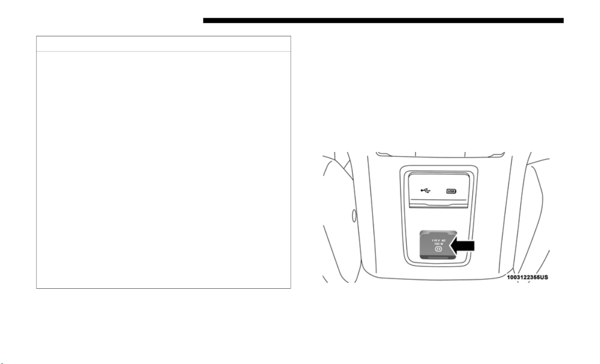
184 GETTING TO KNOW YOUR VEHICLE
Power Inverter — If Equipped
There is a 115 Volt, 150 Watt inverter outlet located on the
back of the center console to convert DC current to AC
current.
This outlet can power cellular phones, electronics and other
low power
devices requiring power up to 150 Watts. Certain
high-end video game consoles exceed this power limit, as
will most power tools.
Power Inverter
CAUTION!
• M
any accessories that can be plugged in draw power
from the
vehicle's battery, even when not in use (i.e.,
cellular phones, etc.). Eventually, if plugged in long
enough, the vehicle's battery will discharge sufficiently
to degrade battery life and/or prevent the engine from
starting.
• Accessories that draw higher power (i.e., coolers,
vacuum c
leaners, lights, etc.), will degrade the battery
even more quickly. Only use these intermittently and
with greater caution.
• After the use of high power draw accessories, or long
periods
of the vehicle not being started (with accesso-
ries still plugged in), the vehicle must be driven a suffi-
cient length of time to allow the alternator to recharge
t
he vehic
le's battery.
• Power outlets are designed for accessory plugs only. Do
not hang
any type of accessory or accessory bracket
from the plug. Improper use of the power outlet can
cause damage.
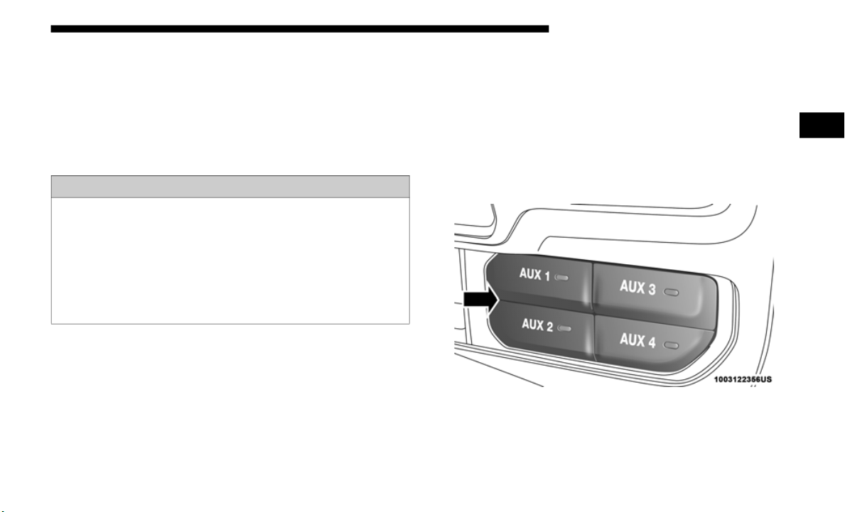
GETTING TO KNOW YOUR VEHICLE 185
The power inverter is designed with built-in overload
protection. If the power rating of 150 Watts is exceeded, the
power inverter automatically shuts down. Once the electrical
device has been removed from the outlet, the inverter should
automatically reset. If the power rating exceeds approxi
-
mately 170 Watts, the power inverter may have to be reset
manually.
Auxiliary Switches — If Equipped
Four auxiliary switches located in the lower switch bank of
the instrument panel can be used to power various electrical
devices. You have the ability to configure the functionality of
the auxiliary switches via the Uconnect settings. All switches
can be configured for setting the switch type operation to
latching or momentary, power source of either battery or
ignition, and ability to hold last state across key cycles.
Auxiliary Switches
WARNING!
To avoid serious injury or death:
• D
o not insert any objects into the receptacles.
• Do not tou
ch with wet hands.
• Close th
e lid when not in use.
• If this
outlet is mishandled, it may cause an electric
shock an
d failure.
2
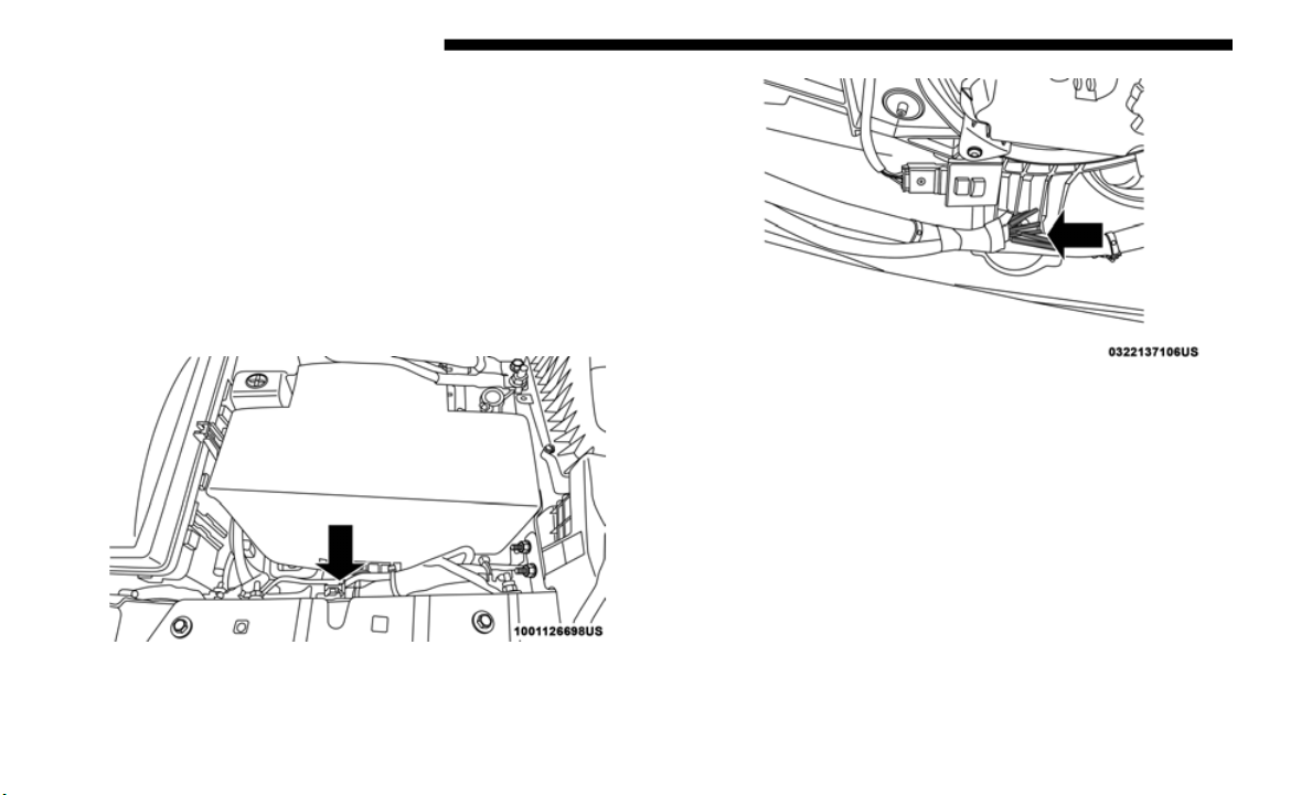
186 GETTING TO KNOW YOUR VEHICLE
NOTE:
Holding last state conditions are met when switch type is set
to latch
ing and power source is set to ignition.
For more information, refer to “Uconnect Settings” in
“Multime
dia”.
The auxiliary switches manage the relays that power four
b
l
unt cu
t wires. These wires are located under the instru-
ment panel in the passenger compartment and under the
h
ood to
the right, near the battery.
Auxiliary Switch Connections – Under Hood
Auxiliary Switch Connections – Under Instrument Panel
In addition to the four auxiliary switch wires, a fused battery
wire and
ignition wire are also located in the interior, in the
passenger side under the instrument panel.
A kit of splices and heat shrink tubing are provided with the
auxiliar
y switches to aid in the connection/installation of
your electrical devices.

GETTING TO KNOW YOUR VEHICLE 187
Wire Color Chart
ROOF LUGGAGE RACK — IF EQUIPPED
NOTE:
Roof rack applications are for Hard Top models ONLY.
The
load carried on the roof, when equipped with a luggage
rack, mu
st not exceed 100 lbs (45 kg), this includes the weight
of the crossbars, and it should be uniformly distributed over
the cargo area.
Crossbars should always be used whenever cargo is placed
on the
roof rack. Check the straps frequently to be sure that
the load remains securely attached.
NOTE:
Crossbars can be purchased at an authorized dealer through
Mopar p
arts.
Circuit Function Fuse Wire Color Locations
Aux Switch 1 F93 – 40 Amp Beige/Pink
Interior (passenger side under instrument
p
anel)
& Underhood (right side near battery)
Aux Switch 2 F92 – 40 Amp Green/Pink
Interior (passenger side under instrument
panel)
& Underhood (right side near battery)
Aux Switch 3 F103 – 15 Amp Orange/Pink
Interior (passenger side under instrument
panel)
& Underhood (right side near battery)
Aux Switch 4 F108 – 15 Amp Dark Blue/Pink
Interior (passenger side under instrument
panel)
& Underhood (right side near battery)
Battery F72 – 10 Amp Red/White
Interior (passenger side under instrument
panel)
Ign
ition F50 – 10 Amp Pink/Orange
Interior (passenger side under instrument
panel)
2

188 GETTING TO KNOW YOUR VEHICLE
(Continued)
External racks do not increase the total load carrying
capacity of the vehicle. Be sure that the total occupant and
luggage load inside the vehicle, plus the load on the luggage
rack, do not exceed the maximum vehicle load capacity.
WARNING!
Cargo must be securely tied down before driving your
vehicle.
Improperly secured loads can fly off the vehicle,
particularly at high speeds, resulting in personal injury
or property damage. Follow the roof rack cautions when
carrying cargo on your roof rack.
CAUTION!
• To avoid damage to the roof rack and vehicle, do not
exceed the maximum roof rack load capacity. Always
distribute heavy loads as evenly as possible and secure
the load appropriately.
• Long loads, which extend over the windshield, should
be sec
ured to both the front and rear of the vehicle.
• Place a blanket or other protection between the surface
of the roof and the load.
• Travel at reduced speeds and turn corners carefully
when carrying large or heavy loads on the roof rack.
Wind forces, due to natural causes or nearby truck
traffic, can add sudden upward loads. It is recom
-
mended to not carry large flat loads, such as wood
p
anels
or surfboards, which may result in damage to
the cargo or your vehicle.
• Load should always be secured to cross bars first, with
tie dow
n loops used as additional securing points if
needed. Tie loops are intended as supplementary tie
down points only. Do not use ratcheting mechanisms
with the tie loops. Check the straps frequently to be
sure that the load remains securely attached.
CAUTION! (Continued)
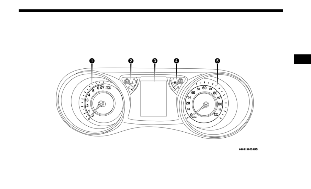
189
GETTING TO KNOW YOUR INSTRUMENT PANEL
INSTRUMENT CLUSTER
Base Instrument Cluster
3
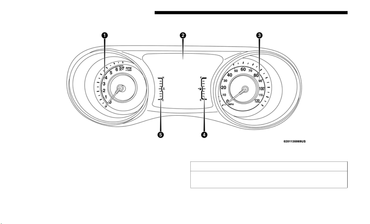
190 GETTING TO KNOW YOUR INSTRUMENT PANEL
Premium Instrument Cluster
Instrument Cluster Descriptions
Base Instrument Cluster Descriptions
1. Tachometer
• Indica
tes the engine speed in revolutions per minute
(RPM x
1000).
CAUTION!
Do not operate the engine with the tachometer pointer in
the red
area. Engine damage will occur.

GETTING TO KNOW YOUR INSTRUMENT PANEL 191
2. Temperature Gauge
• The temperature gauge shows engine coolant tempera-
ture.
Any reading within the normal range indicates
that th
e engine cooling system is operating satisfacto-
rily.
• T
he gauge pointer will likely indicate a higher tempera-
ture wh
en driving in hot weather, up mountain grades,
or when
towing a trailer. It should not be allowed to
exceed the upper limits of the normal operating range.
3. Instrument Cluster Display
• The in
strument cluster display features a driver-inter-
active
display. Refer to “Instrument Cluster Display” in
“Gettin
g To Know Your Instrument Panel” for further
information.
4. Fuel Gauge
• The po
inter shows the level of fuel in the fuel tank
when th
e ignition switch is in the ON/RUN position.
• The fuel pump symbol points to the side of the
vehicle where the fuel filler door is located.
5. S
peedometer
• Indica
tes vehicle speed.
Premiu
m Instrument Cluster Descriptions
1. Tachometer
• Indic
ates the engine speed in revolutions per minute
(RPM x
1000).
WARNING!
A hot engine cooling system is dangerous. You or others
could be
badly burned by steam or boiling coolant. You
may want to call an authorized dealer for service if your
vehicle overheats.
CAUTION!
Driving with a hot engine cooling system could damage
you
r vehic
le. If the temperature gauge reads “H” pull
over and stop the vehicle. Idle the vehicle with the air
conditioner turned off until the pointer drops back into
the normal range. If the pointer remains on the “H”, turn
the engine off immediately and call an authorized dealer
for service.
CAUTION!
Do not operate the engine with the tachometer pointer in
the red
area. Engine damage will occur.
3

192 GETTING TO KNOW YOUR INSTRUMENT PANEL
2. Instrument Cluster Display
• The instrument cluster display features a driver-inter-
active
display. Refer to “Instrument Cluster Display” in
“Gettin
g To Know Your Instrument Panel” for further
information.
3. Speedometer
• Indica
tes vehicle speed.
4. Fuel
Gauge
• The po
inter shows the level of fuel in the fuel tank
when t
he ignition switch is in the ON/RUN position.
• The fuel pump symbol points to the side of the
vehicle where the fuel filler door is located.
5. T
emperature Gauge
• The te
mperature gauge shows engine coolant tempera-
ture.
Any reading within the normal range indicates
that th
e engine cooling system is operating satisfacto-
rily.
• T
he gauge pointer will likely indicate a higher tempera-
ture wh
en driving in hot weather, up mountain grades,
or when
towing a trailer. It should not be allowed to
exceed the upper limits of the normal operating range.
WARNING!
A hot engine cooling system is dangerous. You or others
could be
badly burned by steam or boiling coolant. You
may want to call an authorized dealer for service if your
vehicle overheats.
CAUTION!
Driving with a hot engine cooling system could damage
you
r vehic
le. If the temperature gauge reads “H” pull
over and stop the vehicle. Idle the vehicle with the air
conditioner turned off until the pointer drops back into
the normal range. If the pointer remains on the “H”, turn
the engine off immediately and call an authorized dealer
for service.
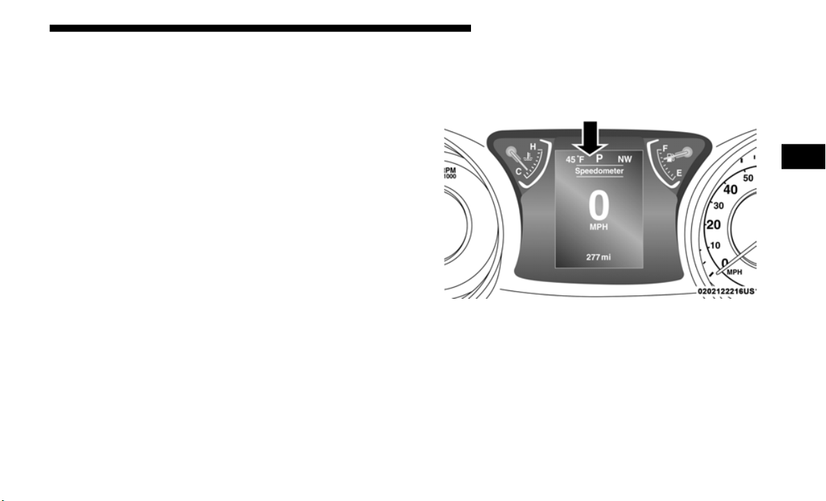
GETTING TO KNOW YOUR INSTRUMENT PANEL 193
INSTRUMENT CLUSTER DISPLAY
Your vehicle may be equipped with an instrument cluster
display, which offers useful information to the driver. With
the ignition in the STOP/OFF mode, opening/closing of a
door will activate the display for viewing, and display the
total miles, or kilometers, in the odometer. Your instrument
cluster display is designed to display important information
about your vehicle’s systems and features. Using a driver
interactive display located on the instrument panel, your
instrument cluster display can show you how systems are
working and give you warnings when they aren’t. The
steering wheel mounted controls allow you to scroll through
and enter the main menus and submenus. You can access the
specific information you want and make selections and
adjustments.
Instrument Cluster Display Location And Controls
The instrument cluster display is located in the center of the
instrument cluster.
3.5 Inch Instrument Cluster Display Location
3
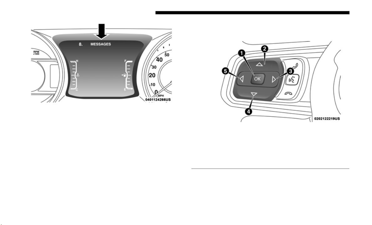
194 GETTING TO KNOW YOUR INSTRUMENT PANEL
7.0 Inch Instrument Cluster Display Location
The system allows the driver to select information by pushing
the foll
owing buttons mounted on the steering wheel:
Instrument Cluster Display Control Buttons
1 — OK Button
2 — Up Arrow Button
3 — Right Arrow Button
4 — Down Arrow Button
5 — Left Arrow Button

GETTING TO KNOW YOUR INSTRUMENT PANEL 195
• Up Arrow Button
Push and release the up arrow
button to scroll
upward through the Main Menu items.
• D
own Arrow Button
Push a
nd release the down arro
w button to scroll
downward through the Main Menu items.
• R
ight Arrow Button
Push a
nd release the right arr
ow button to access
the information screens or submenu screens of a
main me
nu item.
• Left Arrow Button
Push a
nd release the left arr
ow button to access
the information screens or submenu screens of a
main me
nu item.
• OK Button
Push t
he OK butto
n to access/select the information
screens or submenu screens of a Main Menu item. Push
and hold the OK arrow button for two seconds to reset
displayed/selected features that can be reset.
The Main Menu items consists of the following:
• S
peedometer
• Vehicl
e Info
• Off Ro
ad— If Equipped
• Fuel Ec
onomy
• Trip I
nfo
• Stop/St
art — If Equipped
• Audio
• M
essage
s
• Screen
Setup
• Settin
gs
3

196 GETTING TO KNOW YOUR INSTRUMENT PANEL
Oil Change Reset — If Equipped
Your vehicle may be equipped with an engine oil change
indicator system. The “Oil Change Required” message will
display in the instrument cluster display for five seconds
after a single chime has sounded to indicate the next sched
-
uled oil change interval. The engine oil change indicator
s
ystem i
s duty cycle based, which means the engine oil
change interval may fluctuate, dependent upon your
personal driving style.
Unless reset, this message will continue to display each time
you plac
e the ignition in the ON/RUN position. To turn off
the message temporarily, push and release the OK button.
To reset the oil change indicator system (after performing the
scheduled maintenance), refer to the following procedure.
Oil Life Reset
1. Without pushing the brake pedal, place the ignition in the
ON/RUN
mode (do not start the engine).
2. Navigate to "Oil Life" submenu in "Vehicle Info" in the
instru
ment cluster display.
3. Push and hold the OK butt
on until the gauge resets to
100%.
Secondary Method For Oil Change Reset Procedure
1. Without pushing the brake pedal, place the ignition in the
ON/RUN
position (do not start the engine).
2. Fu
lly press the accelerator pedal, slowly, three times
wi
thin
ten seconds.
3. Without pushing the brake pedal, place the ignition in the
OFF/LOCK
position.
NOTE:
If the indicator message illuminates when you start the
vehicle
, the oil change indicator system did not reset. If
necessary, repeat this procedure.
Instrument Cluster Display Menu Items
NOTE:
The instrument cluster display menu items display in the
center
of the instrument cluster. Menu items may vary
depending on your vehicle features.

GETTING TO KNOW YOUR INSTRUMENT PANEL 197
Speedometer
Push and release the up or down
arrow button until the
speedometer menu icon is displayed in the instrument
cluster display. Push and release the OK button to toggle
between MPH and km/h.
Vehicle Info
Push and release the up or down
arrow button until the
Vehicle Info menu icon is displayed in the instrument cluster
display. Push and release the left or right arrow button to
scroll through the information submenus and push and release
the OK button to select or reset the resettable submenus.
Off Road
Push and release the up or down arrow button until the Off
Road me
nu icon is displayed in the instrument cluster
display. Push and release the left or right arrow button to
scroll through the information submenus.
• Drivetrain
• Front W
heel Angle: displays the graphical and numer-
ical v
alue of calculated average front wheel angle from
the ste
ering wheel orientation.
• Transfer Case Lock Status: displays "Lock" graphic
only du
ring 4WD High, 4WD High Part Time, 4WD
Low status.
• Axle Lock And Sway Bar Status (If Equipped): displays
front
and rear or rear only axle locker graphic, and
sway bar connection graphic with text message
(connected or disconnected).
• Pitch And Roll
• Displa
ys the pitch and roll of the vehicle in the graphic
with th
e angle number on the screen.
NOTE:
When vehicle speed becomes too high to display the pitch
a
nd rol
l, “- -” will display in place of the numbers, and the
graphic will be greyed out. A message indicating the neces
-
sary speed for the feature to become available will also
display.
•
Tire Pressure • Coola
nt Temperature
• Transmission Tempera-
ture —
Automatic Trans-
mission Only
• O
il Pressure
• Oil Temperature • Oil L
ife
• Battery Voltage
3

198 GETTING TO KNOW YOUR INSTRUMENT PANEL
Fuel Economy
Push and release the up or down
arrow button until the Fuel
Economy icon is highlighted in the instrument cluster
display. Push and hold the OK button to reset average fuel
economy feature.
Toggle left or right to select a display with or without
Current
Fuel Economy Information.
• Range – The display shows the estimated distance (mi or
km) tha
t can be traveled with the fuel remaining in the
tank. When the Range value is less than 10
miles (16 kilo-
meters), the Range display will change to a “LOW”
message.
Adding a significant amount of fuel to the
vehicle will turn off the “LOW” message and a new Range
value will display. Range cannot be reset through the OK
button.
NOTE:
Significant changes in driving style or vehicle loading will
greatly a
ffect the actual drivable distance of the vehicle,
regardless of the Range displayed value.
• Average – The display shows the average fuel economy
(MPG,
L/100 km, or km/L) since the last reset.
• C
urrent – This display shows the current fuel economy
(MPG,
L/100 km, km/L) while driving.
Trip Info
Push and release the up or down
arrow button until the Trip
icon/title is highlighted in the instrument cluster display,
then push and release the left or right arrow button to select
Trip A or Trip B.
The Trip A and Trip B information will display the
followin
g:
• Distance
• Average
Fuel Economy
• Elapse
d Time
Hold t
he OK butto
n to reset all the information.
Stop/Start — If Equipped
Push and release the up or down
arrow button until the
Stop/Start icon/title is highlighted in the instrument cluster
display. The screen will display the Stop/Start status.

GETTING TO KNOW YOUR INSTRUMENT PANEL 199
Audio
Push and release the up or down
arrow button until the
Audio Menu icon/title is highlighted in the instrument
cluster display. This menu will display the audio source
information, including the Song name, Artist name, and
audio source with an accompanying graphic.
• Phone Call Status
When a
call is incoming, a Phone Call Status pop-up will
display
on the screen. The pop-up will remain until the
phone is answered or ignored.
NOTE:
The call status will temporarily replace the previous media
source
information displayed on the screen. When the
pop-up is no longer displayed, the display will return to the
last used screen.
Messages
Push and release the up or down
arrow button until the
Messages Menu item is highlighted. This feature shows the
number of stored warning messages. Pushing the right arrow
button will allow you to see what the stored messages are.
When no messages are present, main menu icon will be a
closed
envelope, and “No Stored Messages” will display.
Screen Setup
Push and release the up or down
arrow button until the
Screen Setup Menu Icon/Title is highlighted in the instru-
ment cluster display. Push and release the O
K butto
n to
enter the sub-menus and follow the prompts on the screen as
needed. The Screen Setup feature allows you to change what
information is displayed in the instrument cluster as well as
the location that information is displayed.
Screen Setup Driver Selectable Items
Upper Left
• None
• Compas
s (default setting)
• Outsid
e Temp
• Time
• Ra
nge T
o Empty
• Average
MPG (or L/100km, km/L)
• Curren
t MPG (or L/100km, km/L)
• Trip A
Distance
• Trip B
Distance
3

200 GETTING TO KNOW YOUR INSTRUMENT PANEL
Center
• None
• Compas
s
• Outsid
e Temp
• Time
• Ra
nge t
o Empty
• Average
MPG (or L/100km, km/L)
• Curren
t MPG (or L/100km, km/L)
• Trip A
Distance
• Trip B
Distance
• Audio
• S
peedo
meter
• Menu T
itle (default setting)
Upper
Right
• None
• Compas
s
• Outsid
e Temp (default setting)
• Time
• Ra
nge T
o Empty
• Average
MPG (or L/100km, km/L)
• Curren
t MPG (or L/100km, km/L)
• Trip A
Distance
• Trip B
Distance
Gear D
isplay — If Equipped
• Full (default setting)
• Single
Cu
rren
t Gear
• On
• Off (d
efault setting)
Odomete
r — If Equipped
• Show (default setting)
• Hide

GETTING TO KNOW YOUR INSTRUMENT PANEL 201
Favorite Menus
• Speedometer
• Vehicl
e Info
• Off Ro
ad – If Equipped (show/hide)
• Fuel Ec
onomy (show/hide)
• Trip I
nfo (Show/Hide)
• Stop/St
art
• Audio
(show/hide)
• Message
s
• Screen
Setup
Defaul
ts (Restores All Settings To Default Settings)
• Cancel
• Restor
e
The me
nu with (show/hide) means user can press OK
button
to choose show or hide this menu on the instrument
cluster display.
Battery Saver On/Battery Saver Mode Message —
Electrical Load Reduction Actions — If Equipped
This vehicle is equipped with an Intelligent Battery Sensor
(IBS) to perform additional monitoring of the electrical
system and status of the vehicle battery.
In cases when the IBS detects charging system failure, or the
vehicle
battery conditions are deteriorating, electrical load
reduction actions will take place to extend the driving time
and distance of the vehicle. This is done by reducing power
to or turning off non-essential electrical loads.
Load reduction is only active when the engine is running. It
will dis
play a message if there is a risk of battery depletion to
the point where the vehicle may stall due to lack of electrical
supply, or will not restart after the current drive cycle.
When load reduction is activated, the message “Battery
Saver O
n” or “Battery Saver Mode” will appear in the instru-
ment cluster display.
These messages indicate the vehicle battery has a low state of
c
harge a
nd continues to lose electrical charge at a rate that
the charging system cannot sustain.
3

202 GETTING TO KNOW YOUR INSTRUMENT PANEL
NOTE:
• The charging system is independent from load reduction.
The ch
arging system performs a diagnostic on the
charging system continuously.
• If the Battery Charge Warning Light is on it may indicate a
proble
m with the charging system. Refer to “Battery
Charge Warning Light” in “Warning Lights And
Messages” located in ”Getting To Know Your Instrument
Panel” for further information.
The electrical loads that may be switched off (if equipped), and
vehicle
functions which can be effected by load reduction:
• Heated Seat/Vented Seats/Heated Wheel
• Rear D
efroster And Heated Mirrors
• HVAC S
ystem
• 150W P
ower Inverter System
• Audio
and Telematics System
Loss o
f the battery charge may indicate one or more of the
followin
g conditions:
• The charging system cannot deliver enough electrical
power t
o the vehicle system because the electrical loads are
larger than the capability of charging system. The charging
system is still functioning properly.
• Turning on all possible vehicle electrical loads (e.g. HVAC
to max
settings, exterior and interior lights, overloaded
power outlets +12V, 150W, USB ports) during certain
driving conditions (city driving, towing, frequent stop
-
ping).
• I
nstalling options like additional lights, upfitter electrical
access
ories, audio systems, alarms and similar devices.
• Unusual driving cycles (short trips separated by long
parkin
g periods).
• The vehicle was parked for an extended period of time
(weeks,
months).
• The battery was recently replaced and was not charged
comple
tely.
• The battery was discharged by an electrical load left on
when th
e vehicle was parked.
• The battery was used for an extended period with the
engine
not running to supply radio, lights, chargers, +12V
portable appliances like vacuum cleaner’s, game consoles
and similar devices.

GETTING TO KNOW YOUR INSTRUMENT PANEL 203
What to do when an electrical load reduction action
message is present (“Battery Saver On” or “Battery Saver
Mode”)
During a trip:
• Reduce power to unnecessary loads if possible:
• Turn of
f redundant lights (interior or exterior)
• Check wh
at may be plugged in to power outlets +12V,
150W, U
SB ports
• Check HVAC settings (blower, temperature)
• Check t
he audio settings (volume)
After a
trip:
• Check if any aftermarket equipment was installed (addi-
tional
lights, upfitter electrical accessories, audio systems,
alarms)
and review specifications if any (load and Ignition
Off Draw currents).
• Evaluate the latest driving cycles (distance, driving time
and par
king time).
• The vehicle should have service performed if the message
is stil
l present during consecutive trips and the evaluation
of the vehicle and driving pattern did not help to identify
the cause.
WARNING LIGHTS AND MESSAGES
The warning/indicator lights will illuminate in the instru-
ment panel together with a dedicated message and/or
acoustic
signal when applicable. These indications are indic-
ative and precautionary and as such must not be considered
a
s exhau
stive and/or alternative to the information
contained in the Owner’s Manual, which you are advised to
read carefully in all cases. Always refer to the information in
this chapter in the event of a failure indication. All active tell
-
tales will display first if applicable. The system check menu
may appea
r different based upon equipment options and
current vehicle status. Some telltales are optional and may
not appear.
Red Warning Lights
— Air Bag Warning Light
This warning light will illuminate to indicate a fault with the
air bag,
and will turn on for four to eight seconds as a bulb
check when the ignition is placed in the ON/RUN or ACC/
ON/RUN position. This light will illuminate with a single
chime when a fault with the air bag has been detected, it will
stay on until the fault is cleared. If the light is either not on
during startup, stays on, or turns on while driving, have the
system inspected at an authorized dealer as soon as possible.
3

204 GETTING TO KNOW YOUR INSTRUMENT PANEL
— Brake Warning Light
This warning light monitors various brake functions,
includi
ng brake fluid level and parking brake application. If
the brake light turns on it may indicate that the parking
brake is applied, that the brake fluid level is low, or that there
is a problem with the anti-lock brake system reservoir.
If the light remains on when the parking brake has been
disengage
d, and the fluid level is at the full mark on the
master cylinder reservoir, it indicates a possible brake
hydraulic system malfunction or that a problem with the
Brake Booster has been detected by the Anti-Lock Brake
System (ABS) / Electronic Stability Control (ESC) system. In
this case, the light will remain on until the condition has been
corrected. If the problem is related to the brake booster, the
ABS pump will run when applying the brake, and a brake
pedal pulsation may be felt during each stop.
The dual brake system provides a reserve braking capacity in
the eve
nt of a failure to a portion of the hydraulic system. A
leak in either half of the dual brake system is indicated by the
Brake Warning Light, which will turn on when the brake
fluid level in the master cylinder has dropped below a spec
-
ified level.
The light will remain on until the cause is corrected.
NOTE:
The light may flash momentarily during sharp cornering maneu-
vers, which change fluid level conditions. The vehicle should
h
ave se
rvice performed, and the brake fluid level checked.
If brake failure is indicated, immediate repair is necessary.
Vehicles equipped with the Anti-Lock Brake System (ABS)
are als
o equipped with Electronic Brake Force Distribution
(EBD). In the event of an EBD failure, the Brake Warning
Light will turn on along with the ABS Light. Immediate
repair to the ABS system is required.
Operation of the Brake Warning Light can be checked by
turning
the ignition switch from the OFF position to the ON/
RUN position. The light should illuminate for approximately
two seconds. The light should then turn off unless the
parking brake is applied or a brake fault is detected. If the
light does not illuminate, have the light inspected by an
authorized dealer.
WARNING!
Driving a vehicle with the red brake light on is
dangerous
. Part of the brake system may have failed. It
will take longer to stop the vehicle. You could have a
collision. Have the vehicle checked immediately.

GETTING TO KNOW YOUR INSTRUMENT PANEL 205
The light also will turn on when the parking brake is applied
with the ignition switch in the ON/RUN position.
NOTE:
This light shows only that the parking brake is applied. It
d
oes not
show the degree of brake application.
— Battery Charge Warning Light
This warning light will illuminate when the battery is not
charging p
roperly. If it stays on while the engine is running,
there may be a malfunction with the charging system.
Contact an authorized dealer as soon as possible.
This indicates a possible problem with the electrical system
or a rel
ated component.
— Door Open Warning Light
This in
dicator will illuminate when a door is ajar/open and
not full
y closed.
NOTE:
If the vehicle is moving, there will also be a single chime.
— Electric Power Steering Fault Warning Light
This warning light will turn on when there's a fault with the
E
PS (Ele
ctric Power Steering) system. Refer to “Power
Steering” in “Starting And Operating” for further information.
— Electronic Throttle Control (ETC) Warning Light
This warning light will illuminate to indicate a problem with
the Elec
tronic Throttle Control (ETC) system. If a problem is
detected while the vehicle is running, the light will either
stay on or flash depending on the nature of the problem.
Cycle the ignition when the vehicle is safely and completely
stopped and the transmission is placed in the PARK position.
The light should turn off. If the light remains on with the
vehicle running, your vehicle will usually be drivable;
however, see an authorized dealer for service as soon as
possible.
WARNING!
Continued operation with reduced assist could pose a
safety ri
sk to yourself and others. Service should be
obtained as soon as possible.
3

206 GETTING TO KNOW YOUR INSTRUMENT PANEL
NOTE:
This light may turn on if the accelerator and brake pedals are
pressed
at the same time.
If the light continues to flash when the vehicle is running,
immediat
e service is required and you may experience
reduced performance, an elevated/rough idle, or engine
stall and your vehicle may require towing. The light will
come on when the ignition is placed in the ON/RUN or
ACC/ON/RUN position and remain on briefly as a bulb
check. If the light does not come on during starting, have the
system checked by an authorized dealer.
— Engine Coolant Temperature Warning Light
This warning light warns of an overheated engine condition.
If the e
ngine coolant temperature is too high, this indicator
will illuminate and a single chime will sound. If the tempera
-
ture reaches the upper limit, a continuous chime will sound
for four
minutes or until the engine is able to cool: whichever
comes first.
If the light turns on while driving, safely pull over and stop
the vehi
cle. If the A/C system is on, turn it off. Also, shift the
transmission into NEUTRAL and idle the vehicle. If the
temperature reading does not return to normal, turn the
engine off immediately and call for service.
Refer to “If Your Engine Overheats” in “In Case Of Emer-
gency” for further information.
— Hood Open Warning Light
This indicator will illuminate when the hood is ajar/open
a
nd not
fully closed.
NOTE:
If the vehicle is moving, there will also be a single chime.
— Oil Pressure Warning Light
This war
ning light will illuminate to indicate low engine oil
pressure
. If the light turns on while driving, stop the vehicle,
shut off the engine as soon as possible, and contact an autho
-
rized dealer. A chime will sound when this light turns on.
Do not operate the vehicle until the cause is corrected. This
light doe
s not indicate how much oil is in the engine. The
engine oil level must be checked under the hood.
— Oil Temperature Warning Light
This warning light will illuminate to indicate the engine oil
temperat
ure is high. If the light turns on while driving, stop
the vehicle and shut off the engine as soon as possible. Wait
for oil temperature to return to normal levels.
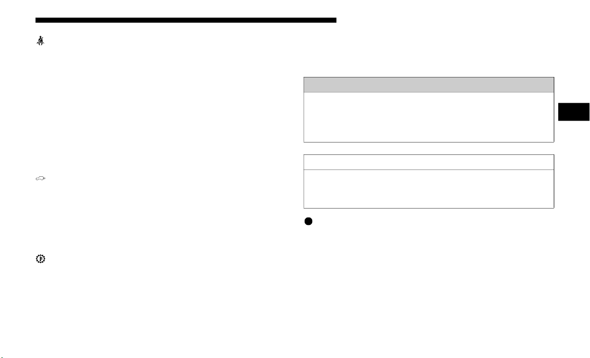
GETTING TO KNOW YOUR INSTRUMENT PANEL 207
— Seat Belt Reminder Warning Light
This warning light indicates when the driver or passenger
seat belt is unbuckled. When the ignition is first placed in the
ON/RUN or ACC/ON/RUN position and if the driver’s
seat belt is unbuckled, a chime will sound and the light will
turn on. When driving, if the driver or front passenger seat
belt remains unbuckled, the Seat Belt Reminder Light will
flash or remain on continuously and a chime will sound.
Refer to “Occupant Restraint Systems” in “Safety” for
further
information.
— Swing Gate Open Warning Light
This war
ning light will illuminate when the swing gate is
open.
NOTE
:
If the vehicle is moving, there will also be a single chime.
— Transmission Temperature Warning Light — If
Equipped
This warning light will illuminate to warn of a high transmis-
sion fluid temperature. This may occur with strenuous usage
s
uch as
trailer towing. If this light turns on, stop the vehicle
and run the engine at idle or slightly faster, with the trans-
mission in PARK or NEUTRAL, until the light turns off.
O
nce the
light turns off, you may continue to drive normally.
— Vehicle Security Warning Light — If Equipped
This li
ght will flash at a fast rate for approximately 15 seconds
when the v
ehicle security alarm is arming, and then will flash
slowly until the vehicle is disarmed.
WARNING!
If you continue operating the vehicle when the
Transmis
sion Temperature Warning Light is illuminated
you could cause the fluid to boil over, come in contact
with hot engine or exhaust components and cause a fire.
CAUTION!
Continuous driving with the Transmission Temperature
W
arning
Light illuminated will eventually cause severe
transmission damage or transmission failure.
3

208 GETTING TO KNOW YOUR INSTRUMENT PANEL
Yellow Warning Lights
— Anti-Lock Brake (ABS) Warning Light
This warning light monitors the Anti-Lock Brake System
(ABS). T
he light will turn on when the ignition is placed in
the ON/RUN or ACC/ON/RUN position and may stay on
for as long as four seconds.
If the ABS light remains on or turns on while driving, then
the Anti
-Lock portion of the brake system is not functioning
and service is required as soon as possible. However, the
conventional brake system will continue to operate
normally, assuming the Brake Warning Light is not also on.
If the ABS light does not turn on when the ignition is placed
in the O
N/RUN or ACC/ON/RUN position, have the brake
system inspected by an authorized dealer.
— Electronic Stability Control (ESC) Active Warning
Light — If Equipped
This warning light will indicate when the Electronic Stability
Control
system is Active. The “ESC Indicator Light” in the
instrument cluster will come on when the ignition is placed
in the ON/RUN or ACC/ON/RUN position, and when ESC
is activated. It should go out with the engine running. If the
“ESC Indicator Light” comes on continuously with the
engine running, a malfunction has been detected in the ESC
system. If this warning light remains on after several ignition
cycles, and the vehicle has been driven several miles (kilome
-
ters) at speeds greater than 30 mph (48 km/h), see an autho-
rized dealer as soon as possible to have the problem
d
iagnosed
and corrected.
• The “ESC Off Indicator Light” and the “ESC Indicator
Light” c
ome on momentarily each time the ignition is
placed in the ON/RUN or ACC/ON/RUN position.
• The ESC system will make buzzing or clicking sounds
when it
is active. This is normal; the sounds will stop when
ESC becomes inactive.
• This light will come on when the vehicle is in an ESC event.
— Electronic S
tability Control (ESC) Off Warning
Light — If Equipped
This warning light indicates the Electronic Stability Control
(
ESC) is
off.
Each time the ignition is turned to ON/RUN or ACC/ON/
RUN, the
ESC system will be on, even if it was turned off
previously.

GETTING TO KNOW YOUR INSTRUMENT PANEL 209
— Loose Fuel Filler Cap Warning Light — If Equipped
This warning light will illuminate when the fuel filler cap is
loose. Properly close the filler cap to disengage the light. If
the light does not turn off, please see an authorized dealer.
— Low Fuel Warning Light
When the fuel level reaches approximately 2.0 gal (7.5 L), this
light will
turn on and a chime will sound. The light will
remain on until fuel is added.
— Low Washer Fluid Warning Light — If Equipped
This warning light will illuminate when the windshield
washer fl
uid is low.
— Engine Check/Malfunction Indicator Warning Light
(MIL)
The Engine Check/Malfunction Indicator Light (MIL) is a
p
art of
an Onboard Diagnostic System called OBD II that
monitors engine and automatic transmission control
systems. This warning light will illuminate when the ignition
is in the ON/RUN position before engine start. If the bulb
does not come on when turning the ignition switch from OFF
to ON/RUN, have the condition checked promptly.
Certain conditions, such as a loose or missing gas cap, poor
quality f
uel, etc., may illuminate the light after engine start.
The vehicle should be serviced if the light stays on through
several typical driving styles. In most situations, the vehicle
will drive normally and will not require towing.
When the engine is running, the MIL may flash to alert
serious
conditions that could lead to immediate loss of
power or severe catalytic converter damage. The vehicle
should be serviced by an authorized dealer as soon as
possible if this occurs.
WARNING!
A malfunctioning catalytic converter, as referenced
above, can
reach higher temperatures than in normal
operating conditions. This can cause a fire if you drive
slowly or park over flammable substances such as dry
plants, wood, cardboard, etc. This could result in death
or serious injury to the driver, occupants or others.
3

210 GETTING TO KNOW YOUR INSTRUMENT PANEL
— Service 4WD Warning Light — If Equipped
This warning light will illuminate to signal a fault with the
4WD syste
m. If the light stays on or comes on during driving,
it means that the 4WD system is not functioning properly
and that service is required. We recommend you drive to the
nearest service center and have the vehicle serviced immedi
-
ately.
— Service Forward Collision Warning (FCW) Light —
If Equipped
This warning light will illuminate to indicate a fault in the
Fo
rward Co
llision Warning System. Contact an authorized
dealer for service.
Refer to “Forward Collision Warning (FCW)” in “Safety” for
further
information.
— Service Stop/Start System Warning Light — If
Equipped
This warning light will illuminate when the Stop/Start
s
ystem is
not functioning properly and service is required.
Contact an authorized dealer for service.
— Speed Control Fault Warning Light
This warning light will illuminate to indicate the Speed
Control
System is not functioning properly and service is
required. Contact an authorized dealer.
— Sway Bar Fault Warning Light
This light will illuminate when there is a fault in the sway bar
disconne
ct system.
— Tire Pressure Monitoring System (TPMS) Warning
Light
The warning light switches on and a message is displayed to
i
ndicate
that the tire pressure is lower than the recom-
mended value and/or that slow pressure loss is occurring. In
t
hese ca
ses, optimal tire duration and fuel consumption may
not be guaranteed.
CAUTION!
Prolonged driving with the Malfunction Indicator Light
(MIL) on
could cause damage to the vehicle control
system. It also could affect fuel economy and
driveability. If the MIL is flashing, severe catalytic
converter damage and power loss will soon occur.
Immediate service is required.

GETTING TO KNOW YOUR INSTRUMENT PANEL 211
Should one or more tires be in the condition mentioned
above, the display will show the indications corresponding
to each tire.
Each tire, including the spare (if provided), should be checked
monthly
when cold and inflated to the inflation pressure
recommended by the vehicle manufacturer on the vehicle
placard or tire inflation pressure label. (If your vehicle has tires
of a different size than the size indicated on the vehicle placard
or tire inflation pressure label, you should determine the
proper tire inflation pressure for those tires.)
As an added safety feature, your vehicle has been equipped
with a
Tire Pressure Monitoring System (TPMS) that illumi-
nates a low tire pressure telltale when one or more of your tires
is sign
ificantly under-inflated. Accordingly, when the low tire
pressure telltale illuminates, you should stop and check your
tires as soon as possible, and inflate them to the proper pres-
sure. Driving on a significantly under-inflated tire causes the
tire to
overheat and can lead to tire failure. Under-inflation also
reduces fuel efficiency and tire tread life, and may affect the
vehicle’s handling and stopping ability.
Please note that the TPMS is not a substitute for proper tire
mainten
ance, and it is the driver’s responsibility to maintain
correct tire pressure, even if under-inflation has not reached
the level to trigger illumination of the TPMS low tire pres
-
sure telltale.
Your vehicle has also been equipped with a TPMS malfunc-
tion indicator to indicate when the system is not operating
p
roperl
y. The TPMS malfunction indicator is combined with
the low tire pressure telltale. When the system detects a
malfunction, the telltale will flash for approximately one
minute and then remain continuously illuminated. This
sequence will continue upon subsequent vehicle start-ups as
long as the malfunction exists. When the malfunction indi
-
cator is illuminated, the system may not be able to detect or
signal l
ow tire pressure as intended. TPMS malfunctions
may occur for a variety of reasons, including the installation
of replacement or alternate tires or wheels on the vehicle that
prevent the TPMS from functioning properly. Always check
the TPMS malfunction telltale after replacing one or more
tires or wheels on your vehicle to ensure that the replace
-
ment or alternate tires and wheels allow the TPMS to
continu
e to function properly.
CAUTION!
Do not continue driving with one or more flat tires as
h
andlin
g may be compromised. Stop the vehicle,
avoiding sharp braking and steering. If a tire puncture
occurs, repair immediately using the dedicated tire
repair kit and contact an authorized dealer as soon as
possible.
3

212 GETTING TO KNOW YOUR INSTRUMENT PANEL
Yellow Indicator Lights
/ — 4WD Indicator Light — If Equipped
This light alerts the driver that the vehicle is in the
four-whee
l drive mode, and the front and rear driveshafts
are mechanically locked together forcing the front and rear
wheels to rotate at the same speed.
/ — 4WD Low Indicator Light — If Equipped
This light alerts the driver that the vehicle is in the
four-whee
l drive LOW mode. The front and rear driveshafts
are mechanically locked together forcing the front and rear
wheels to rotate at the same speed. Low range provides a
greater gear reduction ratio to provide increased torque at
the wheels.
/ — 4WD Part Time Indicator Light — If Equipped
This light alerts the driver that the vehicle is in the
four-whee
l drive part time mode, and the front and rear
driveshafts are mechanically locked together forcing the
front and rear wheels to rotate at the same speed.
— Active Speed Limiter Fault Indicator Light — If
Equipped
This warning light will illuminate to signal when there is a
f
ault de
tected with the Active Speed Limiter.
— Axle Locker Fault Indicator Light
This light indicates when the front and/or rear axle locker
fault ha
s been detected.
CAUTION!
The TPMS has been optimized for the original
equipmen
t tires and wheels. TPMS pressures and
warning have been established for the tire size equipped
on your vehicle. Undesirable system operation or sensor
damage may result when using replacement equipment
that is not of the same size, type, and/or style.
Aftermarket wheels can cause sensor damage. Using
aftermarket tire sealants may cause the Tire Pressure
Monitoring System (TPMS) sensor to become
inoperable. After using an aftermarket tire sealant it is
recommended that you take your vehicle to your
authorized dealer to have your sensor function checked.

GETTING TO KNOW YOUR INSTRUMENT PANEL 213
— Forward Collision Warning Off Indicator Light — If
Equipped
This indicator light illuminates to indicate that Forward
Collisio
n Warning is off.
— Front And Rear Axle Lock Indicator Light
This light indicates when the front, rear, or both axles have
been loc
ked. The telltale will display the lock icon on the
front and rear axles to indicate the current lock status.
/ — Neutral Indicator Light — If Equipped
This light alerts the driver that the vehicle is in the neutral
mode.
— Rear A
xle Lock Indicator Light
This light indicates when the rear axle lock has been acti-
vated.
— Service Adaptive Cruise Control Warning Light —
If Equipped
This light will turn on when a ACC is not operating and
n
eeds se
rvice. Refer to “Adaptive Cruise Control (ACC)” in
“Starting And Operating” for further information.
— Sway Bar Indicator Light — If Equipped
This indicator light will illuminate when the front sway bar
is disco
nnected.
Green Indicator Lights
— Adaptive Cruise Control (ACC) Set With No Target
Detected Indicator Light — If Equipped
This light will turn on when the Adaptive Cruise Control is
set and
there is no target vehicle detected. Refer to "Adaptive
Cruise Control (ACC) — If Equipped" in "Starting And Oper
-
ating" for further information.
— Adaptive Cruise Control (ACC) Set With Target
Light — If Equipped
This will display when the ACC is set and a target vehicle is
d
etected. R
efer to “Adaptive Cruise Control (ACC) — If
Equipped” in “Starting And Operating” for further information.
— 4WD Auto Indicator Light — If Equipped
This light alerts the driver that the vehicle is in the
four-whee
l drive auto mode. The system will provide power
to all four wheels and shift the power between the front and
rear axles as needed. This will provide maximum traction in
dry and slippery conditions.
3

214 GETTING TO KNOW YOUR INSTRUMENT PANEL
— Cruise Control SET Indicator Light — If Equipped
With A Premium Instrument Cluster
This in
dicator light will illuminate when the speed control is set
to the des
ired speed. Refer to “Speed Control — If Equipped” in
“Starting And Operating” for further information.
— Front Fog Indicator Light — If Equipped
This indicator light will illuminate when the front fog lights
are on.
— P
ark/Headlight On Indicator Light
This indicator light will illuminate when the park lights or
headlight
s are turned on.
— Stop/Start Active Indicator Light — If Equipped
This indicator light will illuminate when the Stop/Start func-
tion is in “Autostop” mode.
— Turn Signal Indicator Lights
When th
e left or right turn signal is activated, the turn signal
indicato
r will flash independently and the corresponding
exterior turn signal lamps will flash. Turn signals can be acti
-
vated when the multifunction lever is moved down (left) or
up (right
).
NOTE:
• A continuous chime will sound if the vehicle is driven
more th
an 1 mile (1.6 km) with either turn signal on.
• C
heck for an inoperative outside light bulb if either indi-
cator f
lashes at a rapid rate.
White Indicator Lights
— Adaptive Cruise Control (ACC) Ready Light — If
Equipped
This light will turn on when the vehicle equipped with
Adaptive
Cruise Control (ACC) has been turned on, but not
set. Refer to “Adaptive Cruise Control (ACC) — If
Equipped” in “Starting And Operating” for further informa
-
tion.
— Two Wheel Drive High Indicator Light — If
Equipped With a Premium Cluster
This light alerts the driver that the vehicle is in the two wheel
d
rive hi
gh mode.

GETTING TO KNOW YOUR INSTRUMENT PANEL 215
— Hill Descent Control (HDC) Indicator Light — If
Equipped
This indicator shows when the Hill Descent Control (HDC)
feature
is turned on. The lamp will be on solid when HDC is
armed. HDC can only be armed when the transfer case is in
the “4WD LOW” position and the vehicle speed is less then
30
mph (48 km/h). If these conditions are not met while
attempti
ng to use the HDC feature, the HDC indicator light
will flash on/off.
— Speed Warning Indicator Light — If Equipped
When Set Speed Warning is turned on, the speed warning
telltale
will illuminate in the instrument cluster with a
number matching the set speed. When the set speed is
exceeded, the indication will light up yellow and flash along
with a continuous chime (up to ten seconds or until the speed
is no longer exceeded). Speed Warning can be turned on and
off in the instrument cluster display, for further information
refer to “Instrument Cluster Display Menu Items” in
“Getting To Know Your Instrument Panel.”
The number “55” is only an example of a speed that can be
set.
— Cr
uise Control Ready Indicator Light — If Equipped
With A Premium Instrument Cluster
This li
ght will turn on when the speed control has been turned
on, but
not set. Refer to “Speed Control — If Equipped” in
“Starting And Operating” for further information.
— Cruise Control SET Indicator Light — If Equipped
With Base Instrument Cluster
This in
dicator light will illuminate when the speed control is
set.
Refer
to “Speed Control — If Equipped” in “Starting And
Operatin
g” for further information.
Blue Indicator Lights
— High Beam Indicator Light
This indicator light will illuminate to indicate that the high
beam hea
dlights are on. With the low beams activated, push
the multifunction lever forward (toward the front of the
vehicle) to turn on the high beams. Pull the multifunction
lever rearward (toward the rear of the vehicle) to turn off the
high beams. If the high beams are off, pull the lever toward
you for a temporary high beam on, "flash to pass" scenario.
3

216 GETTING TO KNOW YOUR INSTRUMENT PANEL
Gray Indicator Lights
— Cruise Control Ready Indicator Light — If Equipped
With Base Instrument Cluster
This li
ght will turn on when the speed control has been
turned o
n, but not set. Refer to “Speed Control — If
Equipped” in “Starting And Operating” for further informa
-
tion.
ONBOARD DIAGNOSTIC SYSTEM — OBD II
Your vehicle is equipped with a sophisticated Onboard
Diagnostic system called OBD II. This system monitors the
performance of the emissions, engine, and transmission
control systems. When these systems are operating properly,
your vehicle will provide excellent performance and fuel
economy, as well as engine emissions well within current
government regulations.
If any of these systems require service, the OBD II system
will turn
on the Malfunction Indicator Light (MIL). It will
also store diagnostic codes and other information to assist
your service technician in making repairs. Although your
vehicle will usually be drivable and not need towing, see an
authorized dealer for service as soon as possible.
CAUTION!
• Prolonged driving with the MIL on could cause further
damage t
o the emission control system. It could also
affect fuel economy and driveability. The vehicle must
be serviced before any emissions tests can be
performed.
• If the MIL is flashing while the vehicle is running,
severe c
atalytic converter damage and power loss will
soon occur. Immediate service is required.
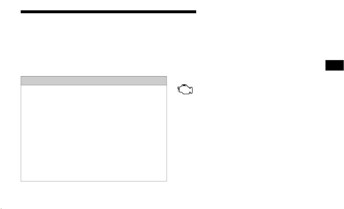
GETTING TO KNOW YOUR INSTRUMENT PANEL 217
Onboard Diagnostic System (OBD II) Cybersecurity
Your vehicle is required to have an Onboard Diagnostic
system (OBD II) and a connection port to allow access to
information related to the performance of your emissions
controls. Authorized service technicians may need to access
this information to assist with the diagnosis and service of
your vehicle and emissions system.
For further information, refer to “Cybersecurity” in “Multi-
media”.
EMISSIONS INSPECTION AND MAINTENANCE
PROGRAMS
In some localities, it may be a legal requirement to pass an
inspection of your vehicle's emissions control system. Failure
to pass could prevent vehicle registration.
For states that require an Inspection and Mainte-
nance (I/M), this check verifies the “Malfunction
Indicato
r Light (MIL)” is functioning and is not on
when the engine is running, and that the OBD II system is
ready for testing.
Normally, the OBD II system will be ready. The OBD II
system ma
y not be ready if your vehicle was recently
serviced, recently had a dead battery or a battery replace
-
ment. If the OBD II system should be determined not ready
for the
I/M test, your vehicle may fail the test.
WARNING!
• ONLY an authorized service technician should connect
equipme
nt to the OBD II connection port in order to
read the VIN, diagnose, or service your vehicle.
• If unauthorized equipment is connected to the OBD II
connecti
on port, such as a driver-behavior tracking
device, it may:
• Be possible that vehicle systems, including safety
related
systems, could be impaired or a loss of
vehicle control could occur that may result in an
accident involving serious injury or death.
• Access, or allow others to access, information stored
in your ve
hicle systems, including personal infor-
mation.
3

218 GETTING TO KNOW YOUR INSTRUMENT PANEL
Your vehicle has a simple ignition actuated test, which you
can use prior to going to the test station. To check if your
vehicle's OBD II system is ready, you must do the following:
1. Cycle the ignition switch to the ON position, but do not
crank o
r start the engine.
NOTE:
If you crank or start the engine, you will have to start this test
o
ver.
2. A
s soon as you cycle the ignition switch to the ON posi-
tion,
you will see the “Malfunction Indicator Light (MIL)”
symbol c
ome on as part of a normal bulb check.
3. Approximately 15 seconds later, one of two things will
happen
:
• The MIL will flash for about ten seconds and then return to
being
fully illuminated until you turn OFF the ignition or
start the engine. This means that your vehicle's OBD II
system is not ready and you should not proceed to the I/M
station.
• The MIL will not flash at all and will remain fully illu-
minate
d until you place the ignition in the off position
or star
t the engine. This means that your vehicle's OBD
II system is ready and you can proceed to the I/M
station.
If your OBD II system is not read
y, you should see an autho-
rized dealer or repair facility. If your vehicle was recently
service
d or had a battery failure or replacement, you may
need to do nothing more than drive your vehicle as you
normally would in order for your OBD II system to update.
A recheck with the above test routine may then indicate that
the system is now ready.
Regardless of whether your vehicle's OBD II system is ready
or not,
if the MIL is illuminated during normal vehicle oper-
ation you should have your vehicle serviced before going to
t
he I/M
station. The I/M station can fail your vehicle
because the MIL is on with the engine running.

219
(Continued)
SAFETY
SAFETY FEATURES
Anti-Lock Brake System (ABS)
The Anti-Lock Brake System (ABS) provides increased
vehicle stability and brake performance under most braking
conditions. The system automatically prevents wheel lock,
and enhances vehicle control during braking.
The ABS performs a self-check cycle to ensure that the ABS
is workin
g properly each time the vehicle is started and
driven. During this self-check, you may hear a slight clicking
sound as well as some related motor noises.
ABS is activated during braking when the system detects one
or more
wheels begin to lock. Road conditions such as ice,
snow, gravel, bumps, railroad tracks, loose debris, or panic
stops may increase the likelihood of ABS activation(s).
You also may experience the following when ABS activates:
• T
he ABS motor noise (it may continue to run for a short
time a
fter the stop).
• The clicking sound of solenoid valves.
• Brake p
edal pulsations.
• A sligh
t drop of the brake pedal at the end of the stop.
These
are all normal characteristics of ABS.
WARNING!
• The ABS contains sophisticated electronic equipment
that m
ay be susceptible to interference caused by
improperly installed or high output radio transmitting
equipment. This interference can cause possible loss of
anti-lock braking capability. Installation of such equip
-
ment should be performed by qualified professionals.
• P
umping of the Anti-Lock Brakes will diminish their
effect
iveness and may lead to a collision. Pumping
makes the stopping distance longer. Just press firmly on
your brake pedal when you need to slow down or stop.
4

220 SAFETY
ABS is designed to function with the OEM tires. Modification
may result in degraded ABS performance.
Anti-Lock Brake Warning Light
The yellow “Anti-Lock Brake Warning Light” will turn on
wh
en the
ignition is turned to the ON/RUN mode and may
stay on for as long as four seconds.
If the “Anti-Lock Brake Warning Light” remains on or comes
on while
driving, it indicates that the anti-lock portion of the
brake system is not functioning and that service is required.
However, the conventional brake system will continue to
operate normally if the “Anti-Lock Brake Warning Light” is
on.
If the “Anti-Lock Brake Warning Light” is on, the brake
system s
hould be serviced as soon as possible to restore the
benefits of anti-lock brakes. If the “Anti-Lock Brake Warning
Light” does not come on when the ignition is turned to the
ON/RUN mode, have the light repaired as soon as possible.
Electronic Brake Control System
Your vehicle is equipped with an advanced Electronic Brake
Control system (EBC). This system includes Electronic Brake
Force Distribution (EBD), Anti-Lock Brake System (ABS),
Brake Assist System (BAS), Hill Start Assist (HSA), Traction
Control System (TCS), Electronic Stability Control (ESC),
and Electronic Roll Mitigation (ERM). These systems work
together to enhance both vehicle stability and control in
various driving conditions.
Your vehicle may also be equipped with Trailer Sway
Control
(TSC), Ready Alert Braking (RAB), Rain Brake
Support (RBS), Dynamic Steering Torque (DST), and Hill
Descent Control (HDC).
• The ABS cannot prevent the natural laws of physics
from ac
ting on the vehicle, nor can it increase braking
or steering efficiency beyond that afforded by the
condition of the vehicle brakes and tires or the traction
afforded.
• The ABS cannot prevent collisions, including those
result
ing from excessive speed in turns, following
another vehicle too closely, or hydroplaning.
• The capabilities of an ABS equipped vehicle must
never b
e exploited in a reckless or dangerous manner
that could jeopardize the user’s safety or the safety of
others.
WARNING! (Continued)

SAFETY 221
Electronic Brake Force Distribution (EBD)
This function manages the distribution of the braking torque
between
the front and rear axles by limiting braking pressure
to the rear axle. This is done to prevent overslip of the rear
wheels to avoid vehicle instability, and to prevent the rear
axle from entering ABS before the front axle.
Brake System Warning Light
The red “Brake System Warning Light” will turn on when
the igni
tion is turned to the ON/RUN mode and may stay on
for as long as four seconds.
If the “Brake System Warning Light” remains on or comes on
while dr
iving, it indicates that the brake system is not func-
tioning properly and that immediate service is required. If
t
he “Br
ake System Warning Light” does not come on when
the ignition is turned to the ON/RUN mode, have the light
repaired as soon as possible.
Brake Assist System (BAS)
The BAS is designed to optimize the vehicle’s braking capa-
bility during emergency braking maneuvers. The system
d
etects
an emergency braking situation by sensing the rate
and amount of brake application and then applies optimum
pressure to the brakes. This can help reduce braking
distances. The BAS complements the anti-lock brake system
(ABS). Applying the brakes very quickly results in the best
BAS assistance. To receive the benefit of the system, you
must apply continuous braking pressure during the stop
-
ping sequence, (do not “pump” the brakes). Do not reduce
b
rake pe
dal pressure unless braking is no longer desired.
Once the brake pedal is released, the BAS is deactivated.
WARNING!
The Brake Assist System (BAS) cannot prevent the
natural
laws of physics from acting on the vehicle, nor
can it increase the traction afforded by prevailing road
conditions. BAS cannot prevent collisions, including
those resulting from excessive speed in turns, driving on
very slippery surfaces, or hydroplaning. The capabilities
of a BAS-equipped vehicle must never be exploited in a
reckless or dangerous manner, which could jeopardize
the user's safety or the safety of others.
4

222 SAFETY
Hill Start Assist (HSA)
The HSA system is designed to mitigate roll back from a
complet
e stop while on an incline. If the driver releases the
brake while stopped on an incline, HSA will continue to hold
the brake pressure for a short period. If the driver does not
apply the throttle before this time expires, the system will
release brake pressure and the vehicle will roll down the hill
as normal.
The following conditions must be met in order for HSA to
activat
e:
• The feature must be enabled.
• The ve
hicle must be stopped.
• Park br
ake must be off.
• Driver
door must be closed. (If the doors are attached, then
the do
or must be closed. If the doors are detached then the
driver's seatbelt must be buckled.)
• The vehicle must be on a sufficient grade.
• The gea
r selection must match vehicle uphill direction (i.e.,
vehicl
e facing uphill is in forward gear; vehicle backing
uphill is in REVERSE gear).
• HSA will work in REVERSE gear and all forward gears.
The sys
tem will not activate if the transmission is in PARK
or NEUTRAL. For vehicles equipped with a manual trans
-
mission, if the clutch is pressed, HSA will remain active.
Disabling And Enabling HSA
This feature can be turned on or turned off. To change the current
s
etting
, refer to “Instrument Cluster Display” in “Getting To
Know Your Instrument Panel” for further information.
WARNING!
There may be situations where the Hill Start Assist
(HSA) w
ill not activate and slight rolling may occur,
such as on minor hills or with a loaded vehicle, or while
pulling a trailer. HSA is not a substitute for active
driving involvement. It is always the driver’s
responsibility to be attentive to distance to other
vehicles, people, and objects, and most importantly
brake operation to ensure safe operation of the vehicle
under all road conditions. Your complete attention is
always required while driving to maintain safe control of
your vehicle. Failure to follow these warnings can result
in a collision or serious personal injury.

SAFETY 223
Towing With HSA
HSA will also provide assistance to mitigate roll back while
towing a
trailer.
Traction Control System (TCS)
This system monitors the amount of wheel spin of each of the
driven
wheels. If wheel spin is detected, the TCS may apply
brake pressure to the spinning wheel(s) and/or reduce engine
power to provide enhanced acceleration and stability. A
feature of the TCS, Brake Limited Differential (BLD), functions
similar to a limited slip differential and controls the wheel spin
across a driven axle. If one wheel on a driven axle is spinning
faster than the other, the system will apply the brake of the
spinning wheel. This will allow more engine torque to be
applied to the wheel that is not spinning. BLD may remain
enabled even if TCS and ESC are in a reduced mode.
Electronic Stability Control (ESC)
This system enhances directional control and stability of the
vehicle
under various driving conditions. ESC corrects for
oversteering or understeering of the vehicle by applying the
brake of the appropriate wheel(s) to assist in counteracting
the oversteer or understeer condition. Engine power may
also be reduced to help the vehicle maintain the desired path.
ESC uses sensors in the vehicle to determine the vehicle path
intende
d by the driver and compares it to the actual path of the
vehicle. When the actual path does not match the intended
path, ESC applies the brake of the appropriate wheel to assist
in counteracting the oversteer or understeer condition.
• Oversteer — when the vehicle is turning more than appro-
priate
for the steering wheel position.
• U
ndersteer — when the vehicle is turning less than appro-
priate
for the steering wheel position.
WARNING!
• If you use a trailer brake controller with your trailer, the
traile
r brakes may be activated and deactivated with the
brake switch. If so, there may not be enough brake pres
-
sure to hold both the vehicle and the trailer on a hill
when the
brake pedal is released. In order to avoid
rolling down an incline while resuming acceleration,
manually activate the trailer brake or apply more vehicle
brake pressure prior to releasing the brake pedal.
• HSA is not a parking brake. Always apply the parking
brake
fully when exiting your vehicle. Also, be certain
to place the transmission in PARK.
• Failure to follow these warnings can result in a colli-
sion or
serious personal injury.
4

224 SAFETY
(Continued)
The “ESC Activation/Malfunction Indicator Light” located
in the instrument cluster will start to flash as soon as the ESC
system becomes active. The “ESC Activation/Malfunction
Indicator Light” also flashes when the TCS is active. If the
“ESC Activation/Malfunction Indicator Light” begins to
flash during acceleration, ease up on the accelerator and
apply as little throttle as possible. Be sure to adapt your
speed and driving to the prevailing road conditions.
ESC Operating Modes
NOTE:
Depending upon model and mode of operation, the ESC
system m
ay have multiple operating modes.
WARNING!
• Electronic Stability Control (ESC) cannot prevent the
natura
l laws of physics from acting on the vehicle, nor
can it increase the traction afforded by prevailing road
conditions. ESC cannot prevent accidents, including
those resulting from excessive speed in turns, driving
on very slippery surfaces, or hydroplaning. ESC also
cannot prevent accidents resulting from loss of vehicle
control due to inappropriate driver input for the condi
-
tions. Only a safe, attentive, and skillful driver can
p
revent
accidents. The capabilities of an ESC equipped
vehicle must never be exploited in a reckless or
dangerous manner which could jeopardize the user’s
safety or the safety of others.
• Vehicle modifications, or failure to properly maintain
your vehicle, may change the handling characteristics
of your vehicle, and may negatively affect the perfor
-
mance of the ESC system. Changes to the steering
system,
suspension, braking system, tire type and size
or wheel size may adversely affect ESC performance.
Improperly inflated and unevenly worn tires may also
degrade ESC performance. Any vehicle modification or
poor vehicle maintenance that reduces the effective
-
ness of the ESC system can increase the risk of loss of
ve
hicle
control, vehicle rollover, personal injury and
death.
WARNING! (Continued)

SAFETY 225
ESC On
This is the normal operating mode for the ESC. Whenever
the veh
icle is started, the ESC system will be in this mode.
This mode should be used for most driving conditions. Alter
-
nate ESC modes should only be used for specific reasons as
noted i
n the following paragraphs.
Partial Off
The “Partial Off” mode is intended for times when a more
spirite
d driving experience is desired. This mode may
modify TCS and ESC thresholds for activation, which allows
for more wheel spin than normally allowed. This mode may
be useful if the vehicle becomes stuck.
To enter the “Partial Off” mode, momentarily push the “ESC
Off” swi
tch and the “ESC Off Indicator Light” will illumi-
nate. To turn the ESC on again, momentarily push the “ESC
O
ff” swi
tch and the “ESC Off Indicator Light” will turn off.
NOTE:
For vehicles with multiple partial ESC modes a momentary
b
utton
push will toggle the ESC mode. Multiple momentary
button pushed may be required to return to ESC On.
Full Off — If Equipped
This mode is intended for off-highway or off-road use only
and sho
uld not be used on any public roadways. In this
mode, TCS and ESC features are turned OFF. To enter the
“Full Off” mode, push and hold the “ESC Off” switch for five
seconds while the vehicle is stopped with the engine
running. After five seconds, a chime will sound, the “ESC Off
Indicator Light” will illuminate, and the “ESC OFF” message
will display in the instrument cluster. To turn ESC ON again,
momentarily push the “ESC Off” switch.
WARNING!
• When in “Partial Off” mode, the TCS functionality of
ESC, (
except for the limited slip feature described in
the TCS section), has been disabled and the “ESC Off
Indicator Light” will be illuminated. When in “Partial
Off” mode, the engine power reduction feature of TCS
is disabled, and the enhanced vehicle stability offered
by the ESC system is reduced.
• Trailer Sway control (TSC) is disabled when the ESC
system
is in the “Partial Off” mode.
4
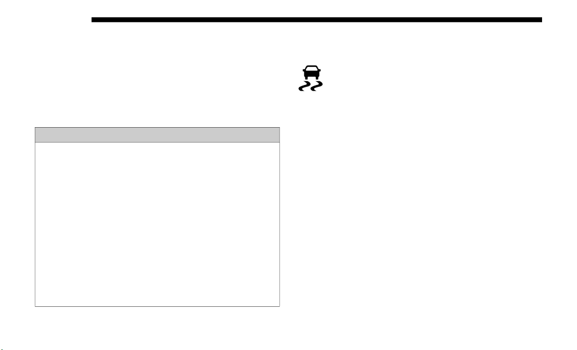
226 SAFETY
NOTE:
System may switch from ESC “Full Off” to “Partial Off”
mode when
vehicle exceeds a predetermined speed. When
the vehicle speed slows below the predetermined speed the
system will return to ESC “Full Off”.
ESC modes may also be affected by drive modes if so
equipped
.
ESC Activation/Malfunction Indicator Light And ESC
OFF Indicator
Light
The “ESC Activation/Malfunction Indicator Light”
in the instrument cluster will come on when the igni-
tion is turned to the ON mode. It should go out with
t
he engin
e running. If the “ESC Activation/Malfunction
Indicator Light” comes on continuously with the engine
running, a malfunction has been detected in the ESC system.
If this light remains on after several ignition cycles, and the
vehicle has been driven several miles (kilometers) at speeds
greater than 30
mph (48 km/h), see an authorized dealer as
soon as
possible to have the problem diagnosed and
corrected.
The “ESC Activation/Malfunction Indicator Light” (located
in the i
nstrument cluster) starts to flash as soon as the tires
lose traction and the ESC system becomes active. The “ESC
Activation/Malfunction Indicator Light” also flashes when
TCS is active. If the “ESC Activation/Malfunction Indicator
Light” begins to flash during acceleration, ease up on the
accelerator and apply as little throttle as possible. Be sure to
adapt your speed and driving to the prevailing road condi
-
tions.
WARNING!
• In the ESC “Full Off” mode, the engine torque reduc-
tion and
stability features are disabled. Therefore,
enhanced
vehicle stability offered by the ESC system is
unavailable. In an emergency evasive maneuver, the
ESC system will not engage to assist in maintaining
stability. ESC “Full Off” mode is intended for
off-highway or off-road use only.
• The Electronic Stability Control (ESC) cannot prevent
the nat
ural laws of physics from acting on the vehicle,
nor can it increase the traction afforded by prevailing
road conditions. ESC cannot prevent all accidents,
including those resulting from excessive speed in
turns, driving on very slippery surfaces, or hydro
-
planing. ESC also cannot prevent collisions.
SAFETY 227
NOTE:
• The “ESC Activation/Malfunction Indicator Light” and
the “ES
C OFF Indicator Light” come on momentarily each
time the ignition is turned ON.
• Each time the ignition is turned ON, the ESC system will
be on e
ven if it was turned off previously.
• The ESC system will make buzzing or clicking sounds
when it
is active. This is normal; the sounds will stop when
ESC becomes inactive following the maneuver that caused
the ESC activation.
The “ESC OFF Indicator Light” indicates the
customer has elected to have the Electronic Stability
C
ontrol
(ESC) in a reduced mode.
Electronic Roll Mitigation (ERM)
This system anticipates the potential for wheel lift by moni-
toring the driver’s steering wheel input and the speed of the
v
ehicle.
When ERM determines that the rate of change of the
steering wheel angle and vehicle’s speed are sufficient to
potentially cause wheel lift, it then applies the appropriate
brake and may also reduce engine power to lessen the chance
that wheel lift will occur. ERM can only reduce the chance of
wheel lift occurring during severe or evasive driving maneu
-
vers; it cannot prevent wheel lift due to other factors, such as
road con
ditions, leaving the roadway, or striking objects or
other vehicles.
NOTE:
ERM is disabled anytime the ESC is in “Full Off” mode (if
equipped
). Refer to “Electronic Stability Control (ESC)” in this
section for a complete explanation of the available ESC modes.
Trailer Sway Control (TSC)
TSC uses sensors in the vehicle to recognize an excessively
swaying tra
iler and will take the appropriate actions to
attempt to stop the sway. TSC will become active automati
-
cally once an excessively swaying trailer is recognized.
WARNING!
Many factors, such as vehicle loading, road conditions
and drivi
ng conditions, influence the chance that wheel
lift or rollover may occur. ERM cannot prevent all wheel
lift or roll overs, especially those that involve leaving the
roadway or striking objects or other vehicles. The
capabilities of an ERM-equipped vehicle must never be
exploited in a reckless or dangerous manner which could
jeopardize the user's safety or the safety of others.
4

228 SAFETY
NOTE:
TSC cannot stop all trailers from swaying. Always use
caution
when towing a trailer and follow the trailer tongue
weight recommendations. Refer to “Trailer Towing” in
“Starting And Operating” for further information.
When TSC is functioning, the “ESC Activation/Malfunction
Indicat
or Light” will flash, the engine power may be reduced
and you may feel the brakes being applied to individual
wheels to attempt to stop the trailer from swaying. TSC is
disabled when the ESC system is in the “Partial Off” or “Full
Off” modes.
Ready Alert Braking (RAB)
Ready Alert Braking may reduce the time required to reach
full br
aking during emergency braking situations. It antici-
pates when an emergency braking situation may occur by
m
onitor
ing how fast the throttle is released by the driver.
The EBC will prepare the brake system for a panic stop.
Rain Brake Support (RBS)
Rain Brake Support may improve braking performance in
wet cond
itions. It will periodically apply a small amount of
brake pressure to remove any water buildup on the front
brake rotors. It functions when the windshield wipers are in
LO or HI speed. When Rain Brake Support is active, there is
no notification to the driver and no driver interaction is
required.
Hill Descent Control (HDC) — If Equipped
HDC is
intended for low speed off road driving while in
4WD Low
Range. HDC maintains vehicle speed while
descending hills during various driving situations. HDC
controls vehicle speed by actively controlling the brakes.
HDC has three states:
1. Off (feature is not enabled and will not activate).
2. Enab
led (feature is enabled and ready but activation
condit
ions are not met, or driver is actively overriding
with brake or throttle application).
3. Active (feature is enabled and actively controlling vehicle
speed)
.
WARNING!
If TSC activates while driving, slow the vehicle down,
stop at
the nearest safe location, and adjust the trailer
load to eliminate trailer sway.

SAFETY 229
Enabling HDC
HDC is enabled by pushing the HDC switch, but the
followin
g conditions must also be met to enable HDC:
• Driveline is in 4WD Low Range
• Vehicl
e speed is below 5 mph (
8 km/h).
• Parking brake is released.
• Driver
door is closed. (If doors are attached, then door
must b
e closed. if doors are detached, then driver seatbelt
must be buckled.)
Activating HDC
Once HDC is enabled it will activate automatically if driven
down a gr
ade of sufficient magnitude. The set speed for
HDC is selectable by the driver, and can be adjusted by using
the gear shift +/-. The following summarizes the HDC set
speeds:
HDC Target Set Speeds
• P = No set speed. HDC may be enabled but will not acti-
vate
• R
=
0.6 mph (
1 km/h)
• N = 1.2 mph (
2 km/h)
• D = 0.6 mph (1 km/h)
• 1s
t = 0.6 mph (
1 km/h)
• 2nd = 1.2 mph (
2 km/h)
• 3rd = 1.8 mph (3 km/h)
• 4t
h = 2.5 mph (
4 km/h)
• 5th = 3.1 mph (
5 km/h)
• 6th = 3.7 mph (
6 km/h)
• 7th = 4.3 mph (
7 km/h)
• 8th = 5.0 mph (
8 km/h)
• 9th = 5.6 mph (
9 km/h) – If Equipped
NOTE:
During HDC the +/- shifter input is used for HDC target
speed s
election, but will not affect the gear chosen by the
transmission. When actively controlling HDC the transmis
-
sion will shift appropriately for the driver-selected set speed
and cor
responding driving conditions.
Driver Override
The driver may override HDC activation with throttle or
brake ap
plication at anytime.
4

230 SAFETY
Deactivating HDC
HDC will be deactivated but remain available if any of the
followin
g conditions occur:
• Driver overrides HDC set speed with throttle or brake
applic
ation.
• Vehicle speed exceeds 20 mph (
32 km/h) but remains
below 40 mph (64 km/h).
• V
ehicle is on a downhill grade of insufficient magnitude,
is on
level ground, or is on an uphill grade.
• Vehicle is shifted to park.
Disabl
ing HDC
HDC will be deactivated and disabled if any of the following
conditi
ons occur:
• The driver pushes the HDC switch.
• The dr
iveline is shifted out of 4WD Low Range.
• The pa
rking brake is applied.
• Driver
door opens (Driver door opens if doors are attached
or dri
ver seatbelt is unbuckled if doors are detached).
• The vehicle is driven greater than 20 mph (
32 km/h) for
greater than 70 seconds.
• The vehicle is driven greater than 40 mph (
64 km/h) (HDC
exits immediately).
• HDC detects excessive brake temperature.
Feedbac
k To The Driver
The instrument cluster has an HDC icon and the HDC switch
has an
indicator light, which offers feedback to the driver
about the state HDC is in.
• The cluster icon and switch indicator light will illuminate
and re
main on solid when HDC is enabled or activated.
This is the normal operating condition for HDC.
• The cluster icon and switch indicator light will flash for
severa
l seconds then extinguish when the driver pushes
the HDC switch but enable conditions are not met.
• The cluster icon and switch indicator light will flash for
severa
l seconds then extinguish when HDC disables due
to excess speed.
• The cluster icon and switch indicator light will flash when
HDC de
activates due to overheated brakes. The flashing
will stop and HDC will activate again once the brakes have
cooled sufficiently.
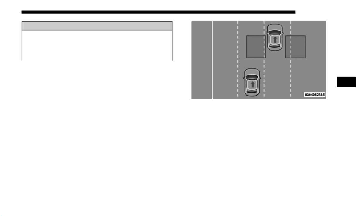
SAFETY 231
AUXILIARY DRIVING SYSTEMS
Blind Spot Monitoring (BSM) — If Equipped
The Blind Spot Monitoring (BSM) system uses two
radar-based sensors, located inside the taillights, to detect
highway licensable vehicles (automobiles, trucks, motorcy
-
cles, etc.) that enter the blind spot zones from the rear/front/
side of
the vehicle.
Rear Detection Zones
When the vehicle is started, the BSM warning light will
momentarily illuminate in both outside rear view mirrors to
let the driver know that the system is operational. The BSM
system sensors operate when the vehicle is in any forward
gear or REVERSE and enters stand-by mode when the
vehicle is in PARK.
WARNING!
HDC is only intended to assist the driver in controlling
vehicle s
peed when descending hills. The driver must
remain attentive to the driving conditions and is
responsible for maintaining a safe vehicle speed.
4
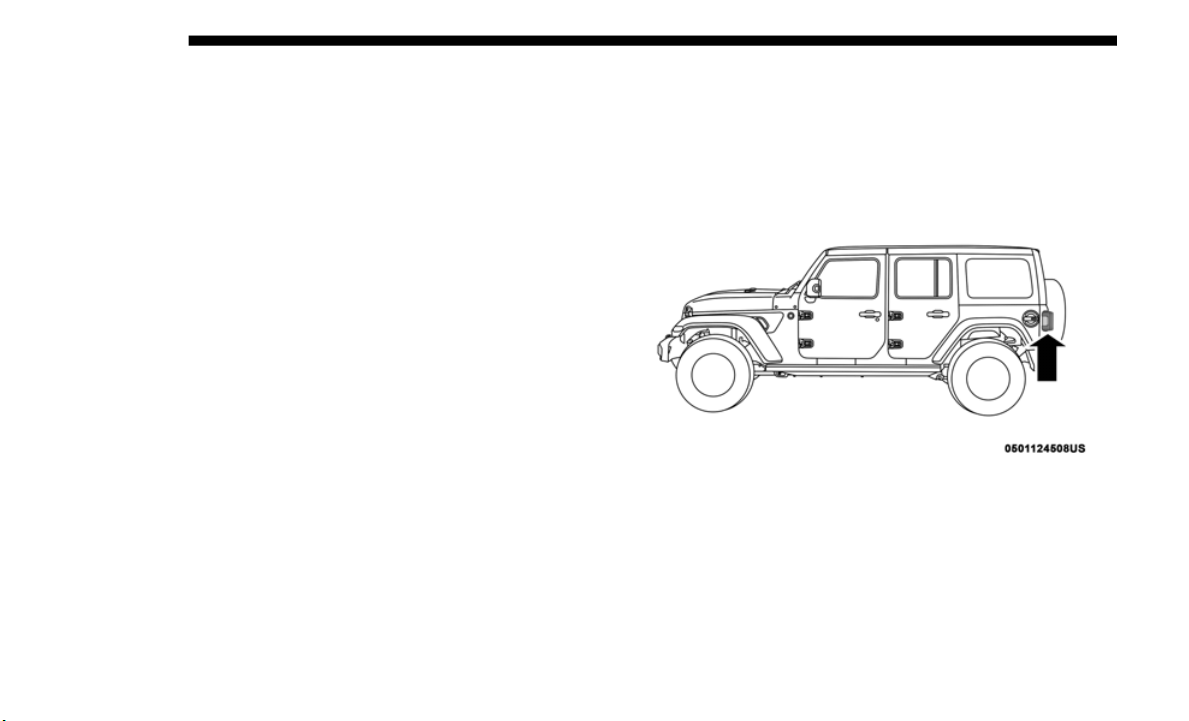
232 SAFETY
The BSM detection zone covers approximately one lane
width on both sides of the vehicle 12 ft (3.8 m). The zone
length st
arts at the outside rear view mirror and extends
approximately 10
ft (3 m) beyond the rear bumper of the
vehicle.
The BSM system monitors the detection zones on
both sides of the vehicle when the vehicle speed reaches
approximately 6
mph (10 km/h) or higher and will alert the
driver o
f vehicles in these areas.
NOTE:
• T
he BSM system DOES NOT alert the driver about rapidly
approac
hing vehicles that are outside the detection zones.
• The BSM system detection zone DOES NOT change if your
vehicle
is towing a trailer. Therefore, visually verify the
adjacent lane is clear for both your vehicle and trailer
before making a lane change. If the trailer or other object
(i.e., bicycle, sports equipment) extends beyond the side of
your vehicle, this may result in the BSM warning light
remaining illuminated the entire time the vehicle is in a
forward gear.
• The Blind Spot Monitoring (BSM) system may experience
drop ou
ts (blinking on and off) of the side mirror Warning
Indicator lamps when a motorcycle or any small object
remains at the side of the vehicle for extended periods of
time (more than a couple of seconds).
The area on taillights, where the radar sensors are located,
m
u
st rem
ain free of snow, ice, and dirt/road contamination
so that the BSM system can function properly. Do not block
the taillights where the radar sensors are located with
foreign objects (bumper stickers, bicycle racks, etc.).
BSM Radar Location (Left Side Shown)
The BSM system notifies the driver of objects in the detection
zones by
illuminating the BSM warning light located in the
outside mirrors in addition to sounding an audible (chime)
alert and reducing the radio volume. Refer to “Modes Of
Operation” for further information.

SAFETY 233
Warning Light Location
The BSM system monitors the detection zone from three
differen
t entry points (side, rear, front) while driving to see
if an alert is necessary. The BSM system will issue an alert
during these types of zone entries.
Entering From The Side
Vehicles that move into your adjacent lanes from either side
of the v
ehicle.
Side Monitoring
4
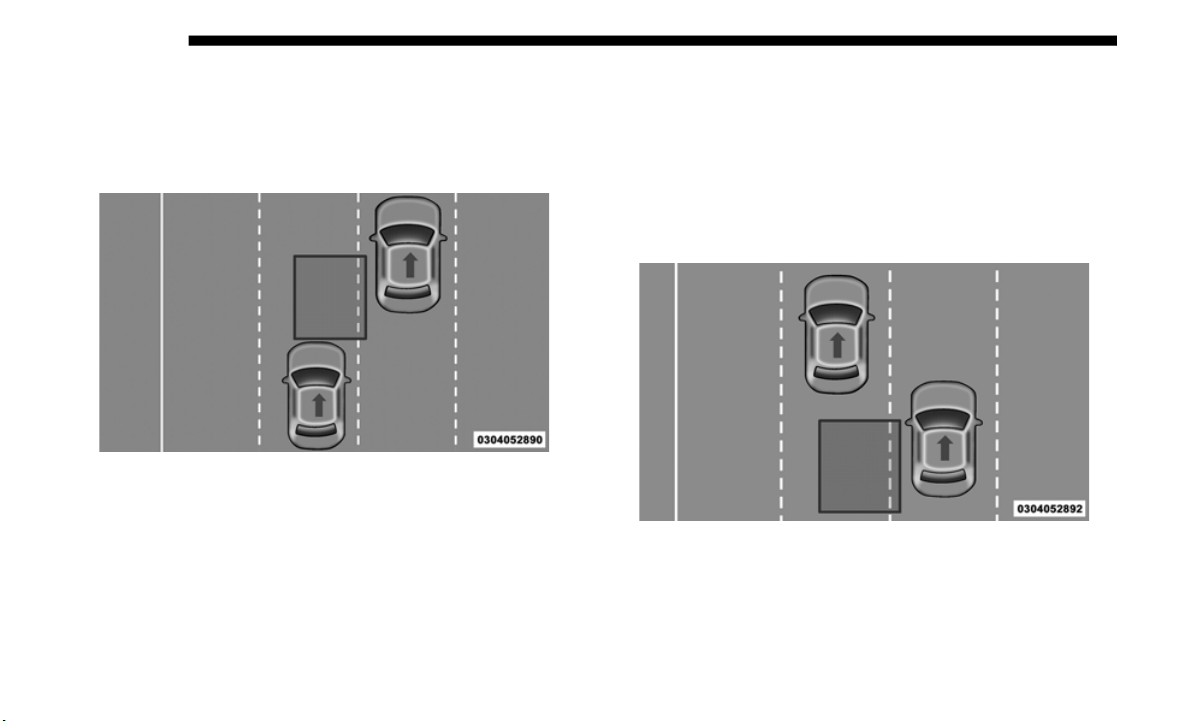
234 SAFETY
Entering From The Rear
Vehicles that come up from behind your vehicle on either
side and
enter the rear detection zone with a relative speed
of less than 30
mph (48 km/h).
Rear Monitoring
Overtaking Traffic
If you pass another vehicle slowly with a relative speed less
than 15 mph (24 km/h) and the vehicle remains in the blind
spot for
approximately 1.5 seconds, the warning light will be
illuminated. If the difference in speed between the two vehi
-
cles is greater than 15 mph (24 km/h), the warning light will
not illu
minate.
Overtaking/Approaching
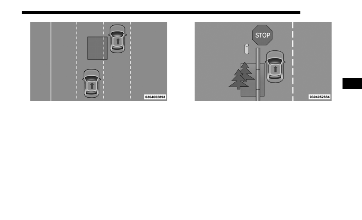
SAFETY 235
Overtaking/Passing
The BSM system is designed not to issue an alert on
stationa
ry objects such as guardrails, posts, walls, foliage,
berms, etc. However, occasionally the system may alert on
such objects. This is normal operation and your vehicle does
not require service.
Stationary Objects
4
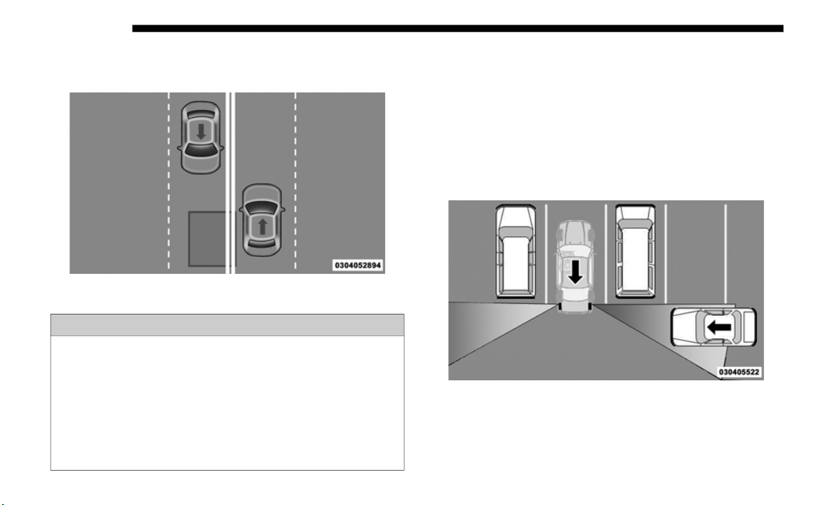
236 SAFETY
The BSM system will not alert you of objects that are traveling
in the opposite direction of the vehicle in adjacent lanes.
Opposing Traffic
Rear Cross Path (RCP)
The Rear Cross Path (RCP) feature is intended to aid the
driver wh
en backing out of parking spaces where their
vision of oncoming vehicles may be blocked. Proceed slowly
and cautiously out of the parking space until the rear end of
the vehicle is exposed. The RCP system will then have a clear
view of the cross traffic and if an oncoming vehicle is
detected, alert the driver.
RCP Detection Zones
WARNING!
The Blind Spot Monitoring system is only an aid to help
detect ob
jects in the blind spot zones. The BSM system is
not designed to detect pedestrians, bicyclists, or animals.
Even if your vehicle is equipped with the BSM system,
always check your vehicle’s mirrors, glance over your
shoulder, and use your turn signal before changing
lanes. Failure to do so can result in serious injury or
death.

SAFETY 237
RCP monitors the rear detection zones on both sides of the
vehicle, for objects that are moving toward the side of the
vehicle with a minimum speed of approximately 3
mph
(5 km/h),
to objects moving a maximum of approximately
20 mph (
32 km/h), such as in parking lot situations.
NOTE:
In a parking lot situation, oncoming vehicles can be obscured
b
y vehic
les parked on either side. If the sensors are blocked
by other structures or vehicles, the system will not be able to
alert the driver.
When RCP is on and the vehicle is in REVERSE, the driver is
alerted
using both the visual and audible alarms, including
reducing the radio volume.
Modes Of Operation
Three selectable modes of operation are available in the
Uconnec
t System. Refer to “Uconnect Settings” in “Multi-
media” for further information.
Blind Spot Alert Lights Only
When operating in Blind Spot Alert mode, the BSM system
wi
ll pro
vide a visual alert in the appropriate side view
mirror based on a detected object. However, when the
system is operating in Rear Cross Path (RCP) mode, the
system will respond with both visual and audible alerts
when a detected object is present. Whenever an audible alert
is requested, the radio is muted.
Blind Spot Alert Lights/Chime
When operating in Blind Spot Alert Lights/Chime mode, the
BSM syst
em will provide a visual alert in the appropriate
side view mirror based on a detected object. If the turn signal
is then activated, and it corresponds to an alert present on
that side of the vehicle, an audible chime will also be
sounded. Whenever a turn signal and detected object are
present on the same side at the same time, both the visual
and audible alerts will be issued. In addition to the audible
alert the radio (if on) will also be muted.
WARNING!
Rear Cross Path Detection (RCP) is not a back up aid
system.
It is intended to be used to help a driver detect
an oncoming vehicle in a parking lot situation. Drivers
must be careful when backing up, even when using RCP.
Always check carefully behind your vehicle, look
behind you, and be sure to check for pedestrians,
animals, other vehicles, obstructions, and blind spots
before backing up. Failure to do so can result in serious
injury or death.
4

238 SAFETY
NOTE:
Whenever an audible alert is requested by the BSM system,
the rad
io is also muted.
When the system is in RCP, the system shall respond with
both vi
sual and audible alerts when a detected object is
present. Whenever an audible alert is requested, the radio is
also muted. Turn/hazard signal status is ignored; the RCP
state always requests the chime.
Blind Spot Alert Off
When the BSM system is turned off there will be no visual or
audible
alerts from either the BSM or RCP systems.
NOTE:
The BSM system will store the current operating mode when
t
he veh
icle is shut off. Each time the vehicle is started the
previously stored mode will be recalled and used.
General Information
The following regulatory statement applies to all Radio
Frequenc
y (RF) devices equipped in this vehicle:
This device complies with Part 15 of the FCC Rules and with
I
n
dustr
y Canada license-exempt RSS standard(s). Operation
is subject to the following two conditions:
1. This device may not cause harmful interference.
2. This
device must accept any interference received,
includ
ing interference that may cause undesired opera-
tion.
NOTE:
Changes or modifications not expressly approved by the
p
arty re
sponsible for compliance could void the user’s
authority to operate the equipment.

SAFETY 239
Forward Collision Warning (FCW) With Mitigation — If
Equipped
The Forward Collision Warning (FCW) system provides the
driver with audible, visual warnings (within the instrument
cluster display), and may apply a haptic warning in the form
of a brake jerk, to warn the driver when it detects a potential
frontal collision. The warnings are intended to provide the
driver with enough time to react, avoid or mitigate the
potential collision.
NOTE:
FCW monitors the information from the forward looking
sensors
as well as Electronic Brake Controller (EBC), to calcu-
late the probability of a forward collision. When the system
d
etermin
es that a forward collision is probable, the driver
will be provided with audible and visual warnings as well as
a possible haptic warning in the form of a brake jerk.
If the driver does not take action based upon these progres-
sive warnings, then the system will provide a limited level of
a
ctive b
raking to help slow the vehicle and mitigate the
potential forward collision. If the driver reacts to the warn
-
ings by braking and the system determines that the driver
intends
to avoid the collision by braking but has not applied
sufficient brake force, the system will compensate and
provide additional brake force as required.
If a FCW with Mitigation event begins at a speed below
32 mph (5
2 km/h), the system may provide the maximum
braking p
ossible to mitigate the potential forward collision.
If the Forward Collision Warning with Mitigation event
stops the vehicle completely, the system will hold the vehicle
at standstill for two seconds and then release the brakes.
FCW Message
When the system determines a collision with the vehicle in
front of
you is no longer probable, the warning message will
be deactivated.
4

240 SAFETY
NOTE:
• The minimum speed for FCW activation is 3 mph (
5 km/h).
• The FCW alerts may be triggered on objects other than
vehicl
es such as guard rails or sign posts based on the
course prediction. This is expected and is a part of normal
FCW activation and functionality.
• It is unsafe to test the FCW system. To prevent such misuse
of the
system, after four Active Braking events within a
key cycle, the Active Braking portion of FCW will be deac
-
tivated until the next Key Cycle.
• T
he FCW system is intended for on-road use only. If the
vehicl
e is taken off-road, the FCW system should be deac-
tivated to prevent unnecessary warnings to the surround-
ings.
• FC
W may not react to irrelevant objects such as overhead
object
s, ground reflections, objects not in the path of the
vehicle, stationary objects that are far away, oncoming
traffic, or leading vehicles with the same or higher rate of
speed.
• FCW will be disabled like ACC, with the unavailable
screen
s.
Turning FCW On or Off
The FCW button is located in the Uconnect display in the
control
settings. Refer to “Uconnect Settings” in “Multi-
media” in the Owner's Manual for further information.
• T
o turn the FCW system on, press the forward collision
button
once to turn the system on.
• To turn the FCW system off, press the forward collision
button
once to turn the system off.
NOTE:
• W
hen the FCW is “on”, this allows the system to warn the
driver
of a possible collision with the vehicle in front.
• When the FCW is “off” prevents the system from warning
the dr
iver of a possible collision with the vehicle in front.
If the FCW is set to “off”, “FCW OFF" will be displayed in
the instrument cluster display.
WARNING!
Forward Collision Warning (FCW) is not intended to
avoid a c
ollision on its own, nor can FCW detect every
type of potential collision. The driver has the
responsibility to avoid a collision by controlling the
vehicle via braking and steering. Failure to follow this
warning could lead to serious injury or death.

SAFETY 241
• When FCW status is set to “Only Warning” prevents the
system from providing limited active braking, or addi-
tional brake support if the driver is not braking adequately
i
n the
event of a potential frontal collision.
• When FCW status is set to “Warning and Braking” this
allows
the system to warn the driver of a possible collision
with the vehicle in front using audible/visual warnings
and it applies autonomous braking.
• The system will retain the last setting selected by the driver
after
ignition shutdown.
FCW Braking Status And Sensitivity
The FCW Sensitivity and Active Braking status are program-
mable through the Uconnect System. Refer to “Uconnect
S
ettings
” in “Multimedia” for further information.
• Far
• When t
he sensitivity of FCW is set to the “Far” setting
and th
e system status is “Only Warning “, this allows
the system to warn the driver of a possible more distant
collisions with the vehicle in front using audible/visual
warnings.
• More cautious drivers that do not mind frequent warn-
ings ma
y prefer this setting.
• Medium
• When t
he sensitivity of FCW is set to the “Medium”
settin
g and the system status is “Only Warning”, this
allows the system to warn the driver of a possible colli
-
sion with the vehicle in front using audible/visual
warnings.
•
Near
• When t
he sensitivity of FCW is set to the “Near” setting
and th
e system status is "Only Warning”, this allows
the system to warn the driver of a possible closer colli
-
sions with the vehicle in front using audible/visual
warnings.
•
This setting provides less reaction time than the “Far”
and “M
edium” settings, which allows for a more
dynamic driving experience.
• More dynamic or aggressive drivers that want to avoid
freque
nt warnings may prefer this setting.
4

242 SAFETY
FCW Limited Warning
If the instrument cluster displays “ACC/FCW Limited Func-
tionality” or “ACC/FCW Limited Functionality Clean Front
Windshi
eld” momentarily, there may be a condition that
limits FCW functionality. Although the vehicle is still driv
-
able under normal conditions, the active braking may not be
fully av
ailable. Once the condition that limited the system
performance is no longer present, the system will return to
its full performance state. If the problem persists, see an
authorized dealer.
Service FCW Warning
If the system turns off, and the instrument cluster displays:
• ACC/FCW Unavailable Service Required
• Cruise
/FCW Unavailable Service Required
This i
ndicates there is an internal system fault. Although the
vehicle
is still drivable under normal conditions, have the
system checked by an authorized dealer.
FCW Sensor Protective Cover
Your vehicle is equipped with a protective cover that is to be
used whe
never the windshield is folded down in order to
protect the FCW sensor. To install the cover, follow the
instructions below.
1. Secure the top part of the cover so that it hinges to the
header
.
2. Swing the cover down and push on it so that it covers the
openin
g.
3. Check to make sure the cover is secured properly.
NOTE:
Be
sure to remove the cover before returning the windshield
t
o the
normal position. Store the cover in the cargo area.
Cleaning Instructions
During windshield down applications, dust/dirt can accu-
mulate in the cover and block the camera lens. Use a micro-
fiber cloth to clean the camera lens, module, and inside
c
over,
being careful not to damage or scratch the module.

SAFETY 243
General Information
The following regulatory statement applies to all Radio
Frequenc
y (RF) devices equipped in this vehicle:
This device complies with Part 15 of the FCC Rules and with
I
n
dustr
y Canada license-exempt RSS standard(s). Operation
is subject to the following two conditions:
1. This device may not cause harmful interference.
2. This
device must accept any interference received,
includ
ing interference that may cause undesired opera-
tion.
NOTE:
Changes or modifications not expressly approved by the
p
arty re
sponsible for compliance could void the user’s
authority to operate the equipment.
Tire Pressure Monitor System (TPMS)
The Tire Pressure Monitor System (TPMS) will warn the
driver of a low tire pressure based on the vehicle recom-
mended cold placard pressure.
NOTE:
The alert warning on the cluster will stay on until the tire is
i
nflate
d to the placard pressure.
The tire pressure will vary with temperature by approxi-
mately 1 psi (7 kPa) for every 12°F (6.5°C). This means that
when the
outside temperature decreases, the tire pressure
will decrease. Tire pressure should always be set based on
cold inflation tire pressure. This is defined as the tire pres
-
sure after the vehicle has not been driven for at least three
h
ours,
or driven less than 1 mile (1.6 km) after a three hour
period.
The cold tire inflation pressure must not exceed the
maximum inflation pressure molded into the tire sidewall.
Refer to “Tires” in “Servicing And Maintenance” for infor
-
mation on how to properly inflate the vehicle’s tires. The tire
p
ressur
e will also increase as the vehicle is driven. This is
normal and there should be no adjustment for this increased
pressure.
The TPMS will warn the driver of a low tire pressure if the
tire pr
essure falls below the low-pressure warning limit for
any reason, including low temperature effects and natural
pressure loss through the tire.
The TPMS will continue to warn the driver of low tire pres-
sure as long as the condition exists, and will not turn off until
t
he tir
e pressure is at or above the recommended cold
placard pressure. Once the low tire pressure warning (Tire
Pressure Monitoring System Warning Light) illuminates,
you must increase the tire pressure to the recommended cold
placard pressure in order for the TPMS Light to turn off.
4

244 SAFETY
(Continued)
NOTE:
When filling warm tires, the tire pressure may need to be
increas
ed up to an additional 4 psi (28 kPa) above the recom-
mended cold placard pressure in order to turn the TPMS
W
arning
Light off.
The system will automatically update and the TPMS
W
a
rning
Light will turn off once the system receives the
updated tire pressures. The vehicle may need to be driven
for up to 20
minutes above 15 mph (24 km/h) in order for the
TPMS to
receive this information.
For example, your vehicle may have a recommended cold
(parked
for more than three hours) placard pressure of 33 psi
(227 kPa). If the ambient temperature is 68°F (20°C) and the
measured tire pressure is 28 psi (193 kPa), a temperature drop
to 20°F (-7°C) will decrease the tire pressure to approximately
24 psi (165 kPa). This tire pressure is low enough to turn on the
TPMS Warning Light. Driving the vehicle may cause the tire
pressure to rise to approximately 28 psi (193 kPa), but the
TPMS Warning Light will still be on. In this situation, the
TPMS Warning Light will turn off only after the tires are
inflated to the vehicle’s recommended cold placard pressure
value.
NOTE:
When filling warm tires, the tire pressure may need to be
i
ncreas
ed up to an additional 4 psi (28 kPa) above the recom-
mended cold placard pressure in order to turn the TPMS
W
arning
Light off.
CAUTION!
• T
he TPMS has been optimized for the original equip-
ment t
ires and wheels. TPMS pressures and warning
have bee
n established for the tire size equipped on
your vehicle. Undesirable system operation or sensor
damage may result when using replacement equipment
that is not of the same size, type, and/or style. The TPM
sensor is not designed for use on aftermarket wheels,
and may contribute to a poor overall system perfor
-
mance. Customers are encouraged to use OEM wheels
to assur
e TPMS feature operation.
• Using aftermarket tire sealants may cause the Tire Pres-
sure M
onitoring System (TPMS) sensor to become
inoperab
le. After using an aftermarket tire sealant it is
recommended that you take your vehicle to an autho
-
rized dealer to have your sensor function checked.
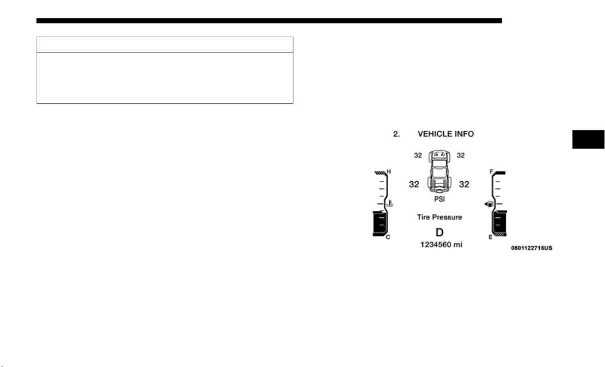
SAFETY 245
NOTE:
• The TPMS is not intended to replace normal tire care and
mainten
ance, or to provide warning of a tire failure or
condition.
• The TPMS should not be used as a tire pressure gauge
while ad
justing your tire pressure.
• Driving on a significantly underinflated tire causes the tire
to over
heat and can lead to tire failure. Underinflation also
reduces fuel efficiency and tire tread life, and may affect
the vehicle’s handling and stopping ability.
• The TPMS is not a substitute for proper tire maintenance,
and it
is the driver’s responsibility to maintain correct tire
pressure using an accurate tire pressure gauge, even if
underinflation has not reached the level to trigger illumi
-
nation of the TPMS Warning Light.
• S
easonal temperature changes will affect tire pressure, and
the TPM
S will monitor the actual tire pressure in the tire.
System Operation
The Tire Pressure Monitor System (TPMS) uses wireless
technolo
gy with wheel rim mounted electronic sensors to
monitor tire pressure levels. Sensors, mounted to each wheel
as part of the valve stem, transmit tire pressure readings to
the receiver module.
Tire Pressure Monitoring Display
NOTE:
It is particularly important for you to check the tire pressure
in all o
f the tires on your vehicle monthly and to maintain the
proper pressure.
• After inspecting or adjusting the tire pressure always
reinsta
ll the valve stem cap. This will prevent moisture
and dirt from entering the valve stem, which could
damage the TPMS sensor.
CAUTION! (Continued)
4
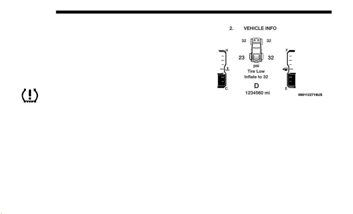
246 SAFETY
The TPMS consists of the following components:
• Receiver module
• Four tir
e pressure monitoring sensors
• Various
tire pressure monitoring system messages, which
display
in the instrument cluster
• Tire pressure monitoring telltale light
Tire Pr
essure Monitoring Low Pressure Warnings
The TPMS Warning Light will illuminate in the
instrument cluster and a chime will sound when tire
p
ressure
is low in one or more of the four active road
tires. In addition, the instrument cluster will display a "Tire
Low" message for a minimum of five seconds, an "Inflate to
XX" message and a graphic showing the pressure values of
each tire with the low tire pressure values in a different color.
Tire Pressure Monitoring Low Pressure Warning
Should this occur, you should stop as soon as possible and
inflate
the tires with low pressure (those in a different color
in the instrument cluster graphic) to the vehicle’s recom
-
mended cold placard pressure value as shown in the "Inflate
to XX" m
essage. Once the system receives the updated tire
pressures, the system will automatically update, the pres
-
sure values in the graphic display in the instrument cluster
will retu
rn to their original color, and the TPMS Warning
Light will turn off.

SAFETY 247
NOTE:
When filling warm tires, the tire pressure may need to be
increas
ed up to an additional 4 psi (28 kPa) above the recom-
mended cold placard pressure in order to turn the TPMS
W
arning
Light off.
The vehicle may need to be driven for up to 20 minutes
a
b
ove 1
5 mph (24 km/h) in order for the TPMS to receive
this in
formation.
Service TPMS Warning
When a system fault is detected, the TPMS Warning Light
will fla
sh on and off for 75 seconds and then remain on solid.
The system fault will also sound a chime. In addition, the
instrument cluster will display a "SERVICE TIRE PRESSURE
SYSTEM" message for a minimum of five seconds and then
display dashes (- -) in place of the pressure value to indicate
which sensor is not being received.
If the ignition is cycled, this sequence will repeat, providing
the syst
em fault still exists. If the system fault no longer
exists, the TPMS Warning Light will no longer flash, and the
“SERVICE TIRE PRESSURE SYSTEM” message will no
longer display, and a pressure value will display in place of
the dashes. A system fault can occur due to any of the
following:
• Jamming due to electronic devices or driving next to facil-
ities
emitting the same radio frequencies as the TPMS
sensors
.
• Installing some form of aftermarket window tinting that
affect
s radio wave signals.
• Lots of snow or ice around the wheels or wheel housings.
• Using t
ire chains on the vehicle.
• Using wh
eels/tires not equipped with TPMS sensors.
Vehicl
es With Compact Spare or Non-Matching Full Size
Spare
1. T
he compact spare tire or non-matching full size does not
have a
tire pressure monitoring sensor. Therefore, the TPMS
will not monitor the pressure in the compact spare tire.
2. If you install the compact or non-matching full size spare
tire i
n place of a road tire that has a pressure below the
low-pressure warning limit, upon the next ignition cycle,
the TPMS Warning Light will remain on and a chime will
sound. In addition, the graphic in the instrument cluster
will still display a different color pressure value and an
"Inflate to XX" message.
4

248 SAFETY
3. After driving the vehicle for up to 20 minutes above
15 mph (24 km/h), the TPMS Warning Light will flash on
and off
for 75 seconds and then remain on solid. In addi-
tion, the instrument cluster will display a “Service Tire
P
ressur
e System” message for five seconds and then
display dashes (- -) in place of the pressure value.
4. For each subsequent ignition cycle, a chime will sound, the
TPMS W
arning Light will flash on and off for 75 seconds
and then remain on solid, and the instrument cluster will
display a “SERVICE TIRE PRESSURE SYSTEM” message
for five seconds and then display dashes (- -) in place of the
pressure value.
5. Once you repair or replace the original road tire and rein-
stall
it on the vehicle in place of the compact spare or
non-mat
ching full size, the TPMS will update automati-
cally. In addition, the TPMS Warning Light will turn off
a
nd the
graphic in the instrument cluster will display a
new pressure value instead of dashes (- -), as long as no
tire pressure is below the low-pressure warning limit in
any of the four active road tires. The vehicle may need to
be driven for up to 20
minutes above 15 mph (24 km/h)
in orde
r for the TPMS to receive this information.
Vehicles With a Full Size Matching Spare
1. If your vehicle is equipped with a matching full-size
spare
wheel and tire assembly, it has a tire pressure moni-
toring sensor, and can be monitored by the Tire Pressure
M
onitor
ing System (TPMS) when swapped with a low
pressure road tire.
2. In the event that the matching full-size spare tire is
swapped
with a low pressure road tire, the next ignition
switch cycle will still show the TPMS Warning Light to be
on, a chime to sound, an Inflate to XX message to appear
in the instrument cluster, and the graphic display will still
show the low tire pressure value in a different color.
3. Driving the vehicle for up to 20 minut
es above 15 mph
(24 km/h) will turn off the TPMS Warning Light as long
as none
of road tires are below the low pressure warning
threshold.

SAFETY 249
TPMS Deactivation — If Equipped
The TPMS can be deactivated if replacing all four wheel and
tire as
semblies (road tires) with wheel and tire assemblies
that do not have TPMS sensors, such as when installing
winter wheel and tire assemblies on your vehicle.
To deactivate the TPMS, first replace all four wheel and tire
assembli
es (road tires) with tires not equipped with Tire Pres-
sure Monitoring (TPM) Sensors. Then, drive the vehicle for
2
0 minutes
above 15 mph (24 km/h). The TPMS will chime, the
TPMS Wa
rning Light will flash on and off for 75 seconds and
then remain on. The instrument cluster will display the
“SERVICE TIRE PRESSURE SYSTEM” message and then
display dashes (--) in place of the pressure values.
Beginning with the next ignition cycle, the TPMS will no
longer c
hime or display the “SERVICE TIRE PRESSURE
SYSTEM” message in the instrument cluster but dashes (--)
will remain in place of the pressure values.
To reactivate the TPMS, replace all four wheel and tire
assembl
ies (road tires) with tires equipped with TPMS
sensors. Then, drive the vehicle for up to 20
minutes above
15 mph (
24 km/h). The TPMS will chime, the TPMS
Warning
Light will flash on and off for 75 seconds and then
turn off. The instrument cluster will display the “SERVICE
TIRE PRESSURE SYSTEM” message and then display pres
-
sure values in place of the dashes. On the next ignition cycle
the "SE
RVICE TIRE PRESSURE SYSTEM" message will no
longer be displayed as long as no system fault exists.
General Information
The following regulatory statement applies to all radio
frequen
cy (RF) devices equipped in this vehicle:
This device complies with Part 15 of the FCC Rules and with
Industr
y Canada license-exempt RSS standard(s). Operation
is subject to the following two conditions:
(1) This device may not cause harmful interference, and
(2) This device must accept any interference received,
includi
ng interference that may cause undesired operation.
NOTE:
Changes or modifications not expressly approved by the
p
arty re
sponsible for compliance could void the user’s
authority to operate the equipment.
4

250 SAFETY
OCCUPANT RESTRAINT SYSTEMS
Some of the most important safety features in your vehicle
are the restraint systems:
Occupant Restraint Systems Features
• Seat Belt Systems
• Supplemental Restraint Systems (SRS) Air Bags
• Child
Restraints
Some of
the safety features described in this section may be stan-
dard equipment on some models, or may be optional equipment
on other
s. If you are not sure, ask an authorized dealer.
Important Safety Precautions
Please pay close attention to the information in this section.
It tells you how to use your restraint system properly, to
keep you and your passengers as safe as possible.
Here are some simple steps you can take to minimize the risk
of harm
from a deploying air bag:
1. Children 12 years old and under should always ride
buckled
up in the rear seat of a vehicle with a rear seat.
2. A child who is not big enough to wear the vehicle seat belt
proper
ly (Refer to “Child Restraints” in this section for
further information) must be secured in the appropriate
child restraint or belt-positioning booster seat in a rear
seating position.
3. If a child from 2 to 12 years old (not in a rear-facing child
restra
int) must ride in the front passenger seat, move the
seat as far back as possible and use the proper child
restraint (Refer to “Child Restraints” in this section for
further information).
4. Never allow children to slide the shoulder belt behind
them o
r under their arm.
5. You should read the instructions provided with your
child
restraint to make sure that you are using it properly.
6. All occupants should always wear their lap and shoulder
belts
properly.
7. The driver and front passenger seats should be moved
back as
far as practical to allow the front air bags room to
inflate.

SAFETY 251
8. Do not lean against the door or window. If your vehicle
has side air bags, and deployment occurs, the side air
bags will inflate forcefully into the space between occu
-
pants and the door and occupants could be injured.
9. I
f the air bag system in this vehicle needs to be modified
to acco
mmodate a disabled person, refer to the
“Customer Assistance” section for customer service
contact information.
Seat Belt Systems
Buckle up even though you are an excellent driver, even on
short trips. Someone on the road may be a poor driver and
could cause a collision that includes you. This can happen far
away from home or on your own street.
Research has shown that seat belts save lives, and they can
reduce t
he seriousness of injuries in a collision. Some of the
worst injuries happen when people are thrown from the
vehicle. Seat belts reduce the possibility of ejection and the
risk of injury caused by striking the inside of the vehicle.
Everyone in a motor vehicle should be belted at all times.
Enhanced Seat Belt Use Reminder System (BeltAlert)
Driver and Passenger BeltAlert (if equipped)
BeltAlert is a feature intended to remind the driver and
outboard front seat passenger (if equipped with outboard
f
ront pa
ssenger seat BeltAlert) to buckle their seat belts. The
Belt Alert feature is active whenever the ignition switch is in
the START or ON/RUN position.
WARNING!
• Never place a rear-facing child restraint in front of an
air bag.
A deploying passenger front air bag can cause
death or serious injury to a child 12 years or younger,
including a child in a rear-facing child restraint.
• Never install a rear-facing child restraint in the front
seat of
a vehicle. Only use a rear-facing child restraint
in the rear seat. If the vehicle does not have a rear seat,
do not transport a rear-facing child restraint in that
vehicle.
4

252 SAFETY
Initial Indication
If the driver is unbuckled when the ignition switch is first in
the STA
RT or ON/RUN position, a chime will signal for a
few seconds. If the driver or outboard front seat passenger (if
equipped with outboard front passenger seat BeltAlert) is
unbuckled when the ignition switch is first in the START or
ON/RUN position the Seat Belt Reminder Light will turn on
and remain on until both outboard front seat belts are
buckled. The outboard front passenger seat BeltAlert is not
active when an outboard front passenger seat is unoccupied.
BeltAlert Warning Sequence
The BeltAlert warning sequence is activated when the
vehicle
is moving above a specified vehicle speed range and
the driver or outboard front seat passenger is unbuckled (if
equipped with outboard front passenger seat BeltAlert) (the
outboard front passenger seat BeltAlert is not active when
the outboard front passenger seat is unoccupied). The
BeltAlert warning sequence starts by blinking the Seat Belt
Reminder Light and sounding an intermittent chime. Once
the BeltAlert warning sequence has completed, the Seat Belt
Reminder Light will remain on until the seat belts are
buckled. The BeltAlert warning sequence may repeat based
on vehicle speed until the driver and occupied outboard
front seat passenger seat belts are buckled. The driver should
instruct all occupants to buckle their seat belts.
Change of Status
If the driver or outboard front seat passenger (if equipped
with out
board front passenger seat BeltAlert) unbuckles
their seat belt while the vehicle is traveling, the BeltAlert
warning sequence will begin until the seat belts are buckled
again.
The outboard front passenger seat BeltAlert is not active
when the
outboard front passenger seat is unoccupied.
BeltAlert may be triggered when an animal or other items are
placed on the outboard front passenger seat or when the seat
is folded flat (if equipped). It is recommended that pets be
restrained in the rear seat (if equipped) in pet harnesses or
pet carriers that are secured by seat belts, and cargo is prop
-
erly stowed.
BeltAlert can be activated or deactivated by an authorized
dealer.
FCA US LLC does not recommend deactivating
BeltAlert.
NOTE:
If BeltAlert has been deactivated and the driver or outboard
front s
eat passenger (if equipped with outboard front
passenger seat BeltAlert) is unbuckled the Seat Belt
Reminder Light will turn on and remain on until the driver
and outboard front seat passenger seat belts are buckled.

SAFETY 253
(Continued)
Lap/Shoulder Belts
All seating positions in your vehicle are equipped with lap/
shoulde
r belts.
The seat belt webbing retractor will lock only during very
s
u
dden
stops or collisions. This feature allows the shoulder
part of the seat belt to move freely with you under normal
conditions. However, in a collision the seat belt will lock and
reduce your risk of striking the inside of the vehicle or being
thrown out of the vehicle.
WARNING!
• Relying on the air bags alone could lead to more severe
injuri
es in a collision. The air bags work with your seat
belt to restrain you properly. In some collisions, the air
bags won’t deploy at all. Always wear your seat belt
even though you have air bags.
• In a collision, you and your passengers can suffer much
greater
injuries if you are not properly buckled up. You
can strike the interior of your vehicle or other passen
-
gers, or you can be thrown out of the vehicle. Always be
sure you
and others in your vehicle are buckled up
properly.
• It is dangerous to ride in a cargo area, inside or outside
of a vehicle. In a collision, people riding in these areas
are more likely to be seriously injured or killed.
• Do not allow people to ride in any area of your vehicle
that is not equipped with seats and seat belts.
• Be sure everyone in your vehicle is in a seat and using
a seat
belt properly. Occupants, including the driver,
should always wear their seat belts whether or not an
air bag is also provided at their seating position to
minimize the risk of severe injury or death in the event
of a crash.
• Wearing your seat belt incorrectly could make your
injuri
es in a collision much worse. You might suffer
internal injuries, or you could even slide out of the seat
belt. Follow these instructions to wear your seat belt
safely and to keep your passengers safe, too.
• Two people should never be belted into a single seat
belt.
People belted together can crash into one another
in a collision, hurting one another badly. Never use a
lap/shoulder belt or a lap belt for more than one person,
no matter what their size.
WARNING! (Continued)
4

254 SAFETY
(Continued)
WARNING!
• A lap belt worn too high can increase the risk of injury
in a c
ollision. The seat belt forces won’t be at the strong
hip and pelvic bones, but across your abdomen. Always
wear the lap part of your seat belt as low as possible and
keep it snug.
• A twisted seat belt may not protect you properly. In a
collisi
on, it could even cut into you. Be sure the seat belt
is flat against your body, without twists. If you can’t
straighten a seat belt in your vehicle, take it to an autho
-
rized dealer immediately and have it fixed.
• A
seat belt that is buckled into the wrong buckle will
not prot
ect you properly. The lap portion could ride too
high on your body, possibly causing internal injuries.
Always buckle your seat belt into the buckle nearest
you.
• A seat belt that is too loose will not protect you prop-
erly. I
n a sudden stop, you could move too far forward,
increas
ing the possibility of injury. Wear your seat belt
snugly.
• A seat belt that is worn under your arm is dangerous.
Your body could strike the inside surfaces of the
vehicle in a collision, increasing head and neck injury.
A seat belt worn under the arm can cause internal inju
-
ries. Ribs aren’t as strong as shoulder bones. Wear the
seat be
lt over your shoulder so that your strongest
bones will take the force in a collision.
• A shoulder belt placed behind you will not protect you
from in
jury during a collision. You are more likely to
hit your head in a collision if you do not wear your
shoulder belt. The lap and shoulder belt are meant to be
used together.
• A frayed or torn seat belt could rip apart in a collision
and le
ave you with no protection. Inspect the seat belt
system periodically, checking for cuts, frays, or loose
parts. Damaged parts must be replaced immediately.
Do not disassemble or modify the seat belt system. Seat
belt assemblies must be replaced after a collision.
WARNING! (Continued)
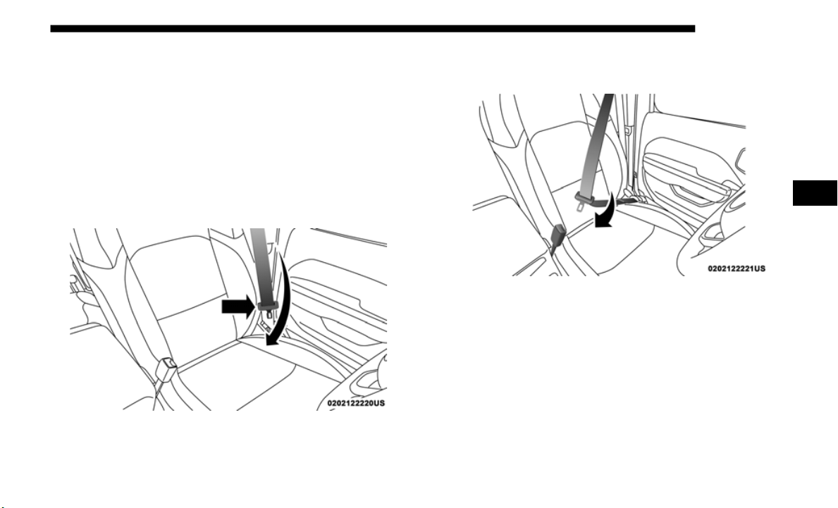
SAFETY 255
Lap/Shoulder Belt Operating Instructions
1. Enter the vehicle and close the door. Sit back and adjust
the sea
t.
2. T
he seat belt latch plate is above the back of the front seat,
a
nd nex
t to your arm in the rear seat (for vehicles
equipped with a rear seat). Grasp the latch plate and pull
out the seat belt. Slide the latch plate up the webbing as
far as necessary to allow the seat belt to go around your
lap.
Pulling Out The Latch Plate
3. W
hen the seat belt is long enough to fit, insert the latch
plate i
nto the buckle until you hear a “click.”
Inserting Latch Plate Into Buckle
4. Position the lap belt so that it is snug and lies low across
your hip
s, below your abdomen. To remove slack in the
lap belt portion, pull up on the shoulder belt. To loosen
the lap belt if it is too tight, tilt the latch plate and pull on
the lap belt. A snug seat belt reduces the risk of sliding
under the seat belt in a collision.
4
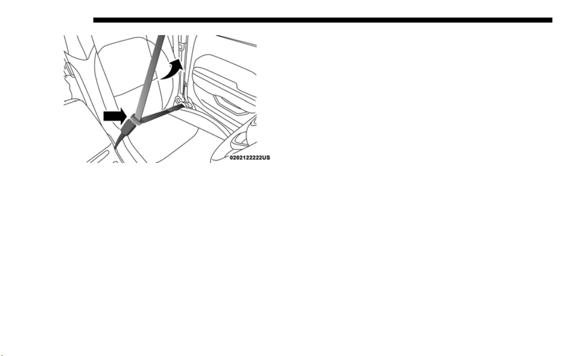
256 SAFETY
Positioning The Lap Belt
5. Position the shoulder belt across the shoulder and chest
with min
imal, if any slack so that it is comfortable and not
resting on your neck. The retractor will withdraw any
slack in the shoulder belt.
6. To release the seat belt, push the red button on the buckle.
The sea
t belt will automatically retract to its stowed posi-
tion. If necessary, slide the latch plate down the webbing
t
o allow
the seat belt to retract fully.
Lap/Shoulder Belt Untwisting Procedure
Use the following procedure to untwist a twisted lap/
shoulder
belt.
1. P
osition the latch plate as close as possible to the anchor
p
oint.
2.
At about 6 to 12 inches
(15 to 30 cm) above the latch plate,
grasp and twist the seat belt webbing 180 degrees to
create a fold that begins immediately above the latch
plate.
3. Slide the latch plate upward over the folded webbing.
The fol
ded webbing must enter the slot at the top of the
latch plate.
4. Continue to slide the latch plate up until it clears the
folded
webbing and the seat belt is no longer twisted.
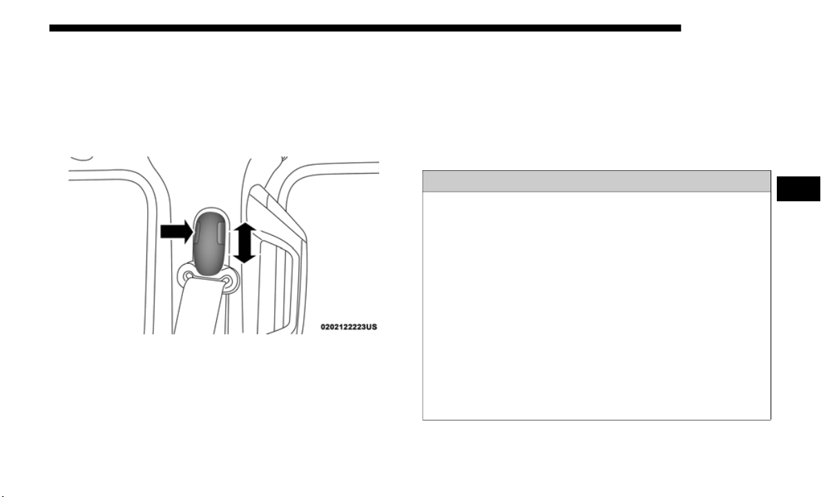
SAFETY 257
Adjustable Upper Shoulder Belt Anchorage
In the driver and outboard front passenger seats, the top of
the shou
lder belt can be adjusted upward or downward to
position the seat belt away from your neck. Push or squeeze
the anchorage button to release the anchorage, and move it
up or down to the position that serves you best.
Adjustable Upper Anchorage
As a guide, if you are shorter than average, you will prefer
the shou
lder belt anchorage in a lower position, and if you
are taller than average, you will prefer the shoulder belt
anchorage in a higher position. After you release the
anchorage button, try to move it up or down to make sure
that it is locked in position.
NOTE:
The adjustable upper shoulder belt anchorage is equipped
with an E
asy Up feature. This feature allows the shoulder
belt anchorage to be adjusted in the upward position without
pushing or squeezing the release button. To verify the
shoulder belt anchorage is latched, pull downward on the
shoulder belt anchorage until it is locked into position.
WARNING!
• Wearing your seat belt incorrectly could make your
injurie
s in a collision much worse. You might suffer
internal injuries, or you could even slide out of the seat
belt. Follow these instructions to wear your seat belt
safely and to keep your passengers safe, too.
• Position the shoulder belt across the shoulder and chest
with mi
nimal, if any slack so that it is comfortable and
not resting on your neck. The retractor will withdraw
any slack in the shoulder belt.
• Misadjustment of the seat belt could reduce the effec-
tiveness
of the safety belt in a crash.
• A
lways make all seat belt height adjustments when the
vehicle
is stationary.
4
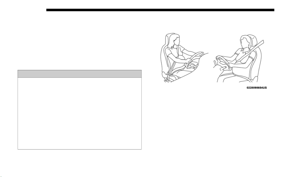
258 SAFETY
Seat Belt Extender
If a seat belt is not long enough to fit properly, even when the
webbing is
fully extended and the adjustable upper shoulder
belt anchorage (if equipped) is in its lowest position, an
authorized dealer can provide you with a Seat Belt Extender.
The Seat Belt Extender should be used only if the existing
seat belt is not long enough. When the Seat Belt Extender is
not required for a different occupant, it must be removed.
Seat Belts And Pregnant Women
Pregnant Women And Seat Belts
Seat belts must be worn by all occupants including pregnant
women: th
e risk of injury in the event of an accident is
reduced for the mother and the unborn child if they are
wearing a seat belt.
Position the lap belt snug and low below the abdomen and
across t
he strong bones of the hips. Place the shoulder belt
across the chest and away from the neck. Never place the
shoulder belt behind the back or under the arm.
WARNING!
• ONLY use a Seat Belt Extender if it is physically
require
d in order to properly fit the original seat belt
system. DO NOT USE the Seat Belt Extender if, when
worn, the distance between the front edge of the Seat
Belt Extender buckle and the center of the occupant’s
body is LESS than 6
inches.
• U
sing a Seat Belt Extender when not needed can
increas
e the risk of serious injury or death in a colli-
sion. Only use the Seat Belt Extender when the lap belt
i
s not lon
g enough and only use in the recommended
seating positions. Remove and store the Seat Belt
Extender when not needed.
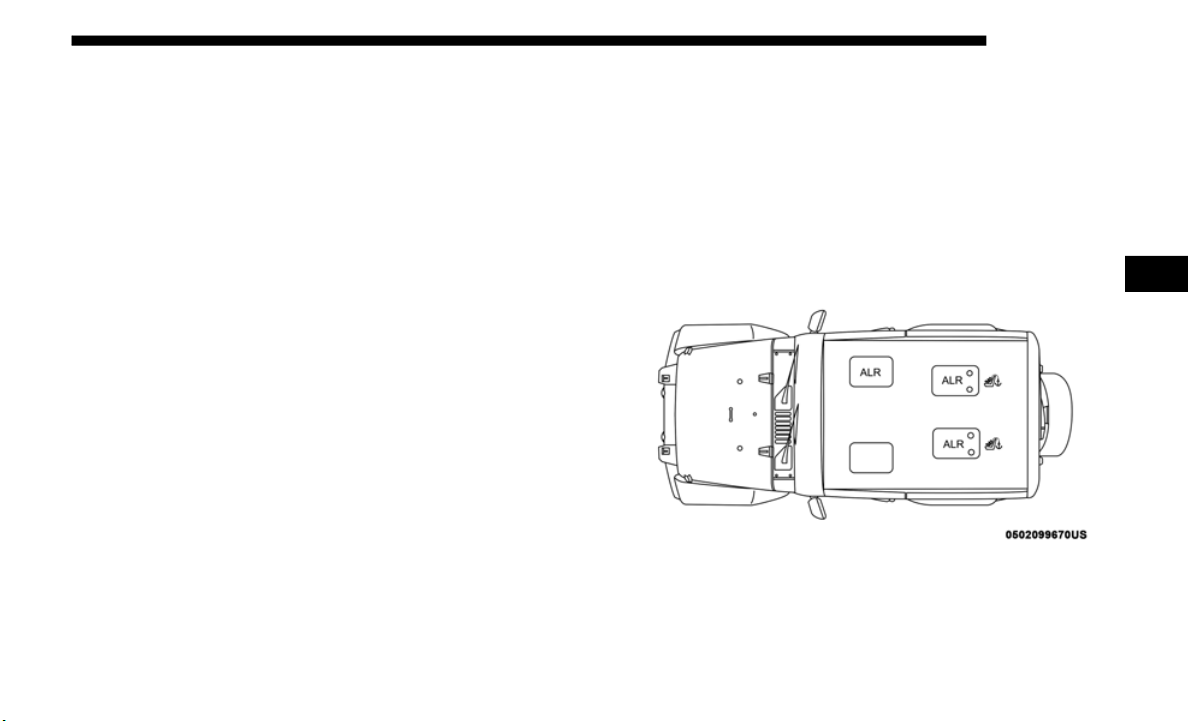
SAFETY 259
Seat Belt Pretensioner
The front outboard seat belt system is equipped with preten-
sioning devices that are designed to remove slack from the
seat bel
t in the event of a collision. These devices may
improve the performance of the seat belt by removing slack
from the seat belt early in a collision. Pretensioners work for
all size occupants, including those in child restraints.
NOTE:
These devices are not a substitute for proper seat belt place-
ment by the occupant. The seat belt still must be worn snugly
a
nd posi
tioned properly.
The pretensioners are triggered by the Occupant Restraint
Controll
er (ORC). Like the air bags, the pretensioners are
single use items. A deployed pretensioner or a deployed air
bag must be replaced immediately.
Energy Management Feature
The front outboard seat belt system is equipped with an
Energy Man
agement feature that may help further reduce
the risk of injury in the event of a collision. The seat belt
system has a retractor assembly that is designed to release
webbing in a controlled manner.
Switchable Automatic Locking Retractor (ALR)
The seat belts in the passenger seating positions are
equipped
with a Switchable Automatic Locking Retractor
(ALR) which is used to secure a child restraint system. For
additional information, refer to “Installing Child Restraints
Using The Vehicle Seat Belt” under the “Child Restraints”
section of this manual. The figure below illustrates the
locking feature for each seating position.
ALR — Switchable Automatic Locking Retractor
(Two-Door M
odels)
4
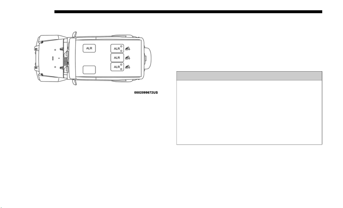
260 SAFETY
ALR — Switchable Automatic Locking Retractor
(Four-Door Models)
If the passenger seating position is equipped with an ALR
a
n
d is b
eing used for normal usage, only pull the seat belt
webbing out far enough to comfortably wrap around the
occupant’s mid-section so as to not activate the ALR. If the
ALR is activated, you will hear a clicking sound as the seat
belt retracts. Allow the webbing to retract completely in this
case and then carefully pull out only the amount of webbing
necessary to comfortably wrap around the occupant’s
mid-section. Slide the latch plate into the buckle until you
hear a "click."
In Automatic Locking Mode, the shoulder belt is automati-
cally pre-locked. The seat belt will still retract to remove any
slack in
the shoulder belt. Use the Automatic Locking Mode
anytime a child restraint is installed in a seating position that
has a seat belt with this feature. Children 12 years old and
under should always be properly restrained in the rear seat
of a vehicle with a rear seat.
How To Engage The Automatic Locking Mode
1. Buckle the combination lap and shoulder belt.
2. Grasp
the shoulder portion and pull downward until the
entire
seat belt is extracted.
WARNING!
• Never place a rear-facing child restraint in front of an
air bag.
A deploying passenger front air bag can cause
death or serious injury to a child 12 years or younger,
including a child in a rear-facing child restraint.
• Never install a rear-facing child restraint in the front
seat of
a vehicle. Only use a rear-facing child restraint
in the rear seat. If the vehicle does not have a rear seat,
do not transport a rear-facing child restraint in that
vehicle.

SAFETY 261
3. Allow the seat belt to retract. As the seat belt retracts, you
will hear a clicking sound. This indicates the seat belt is
now in the Automatic Locking Mode.
How To Disengage The Automatic Locking Mode
Unbuckle the combination lap/shoulder belt and allow it to
retract
completely to disengage the Automatic Locking
Mode and activate the vehicle sensitive (emergency) locking
mode.
Supplemental Restraint Systems (SRS)
Some of the safety features described in this section may be stan-
dard equipment on some models, or may be optional equipment
on others
. If you are not sure, ask an authorized dealer.
The air bag system must be ready to protect you in a collision.
The Occup
ant Restraint Controller (ORC) monitors the internal
circuits and interconnecting wiring associated with the electrical
Air Bag System Components. Your vehicle may be equipped
with the following Air Bag System Components:
Air Bag System Components
• Occupant Restraint Controller (ORC)
• Air Bag
Warning Light
• Steerin
g Wheel and Column
• Instrum
ent Panel
• Knee Im
pact Bolsters
• Driver
and Front Passenger Air Bags
• Seat Be
lt Buckle Switch
• Supplem
ental Side Air Bags
• Front an
d Side Impact Sensors
• Seat Be
lt Pretensioners
WARNING!
• The seat belt assembly must be replaced if the switch-
able Au
tomatic Locking Retractor (ALR) feature or any
other sea
t belt function is not working properly when
checked according to the procedures in the Service
Manual.
• Failure to replace the seat belt assembly could increase
the ris
k of injury in collisions.
• Do not use the Automatic Locking Mode to restrain
occupant
s who are wearing the seat belt or children
who are using booster seats. The locked mode is only
used to install rear-facing or forward-facing child
restraints that have a harness for restraining the child.
4

262 SAFETY
• Seat Track Position Sensors
• Occupant Classification System
Air Bag War
ning Light
The ORC monitors the readiness of the elec-
tronic parts of the air bag system whenever the
ignitio
n switch is in the START or ON/RUN
position. If the ignition switch is in the OFF posi
-
tion or in the ACC position, the air bag system is
not on
and the air bags will not inflate.
The ORC contains a backup power supply system that may
deploy t
he air bag system even if the battery loses power or
it becomes disconnected prior to deployment.
The ORC turns on the Air Bag Warning Light in the instru-
ment panel for approximately four to eight seconds for a
self-ch
eck when the ignition switch is first in the ON/RUN
position. After the self-check, the Air Bag Warning Light will
turn off. If the ORC detects a malfunction in any part of the
system, it turns on the Air Bag Warning Light, either
momentarily or continuously. A single chime will sound to
alert you if the light comes on again after initial startup.
The ORC also includes diagnostics that will illuminate the
instrum
ent panel Air Bag Warning Light if a malfunction is
detected that could affect the air bag system. The diagnostics
also record the nature of the malfunction. While the air bag
system is designed to be maintenance free, if any of the
following occurs, have an authorized dealer service the air
bag system immediately.
• The Air Bag Warning Light does not come on during the
four t
o eight seconds when the ignition switch is first in the
ON/RUN position.
• The Air Bag Warning Light remains on after the four to
eight-s
econd interval.
• The Air Bag Warning Light comes on intermittently or
remain
s on while driving.
NOTE:
If the speedometer, tachometer, or any engine related gauges
a
re not
working, the Occupant Restraint Controller (ORC)
may also be disabled. In this condition the air bags may not
be ready to inflate for your protection. Have an authorized
dealer service the air bag system immediately.
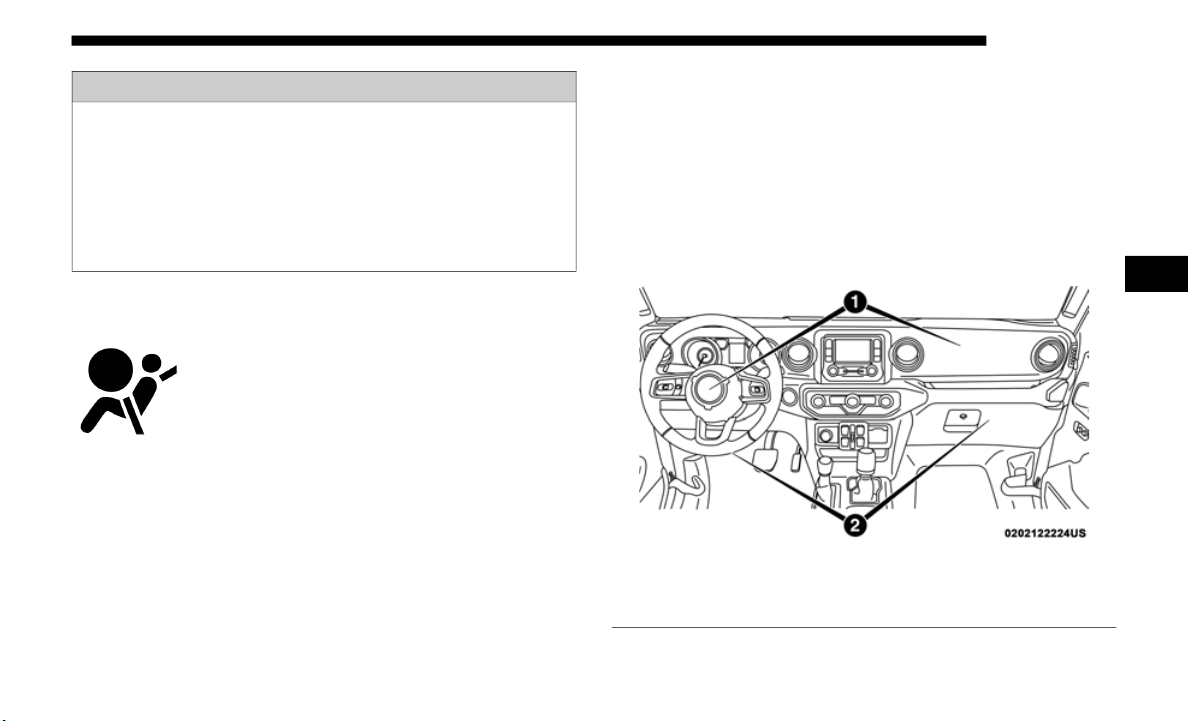
SAFETY 263
Redundant Air Bag Warning Light
If a fault with the Air Bag Warning Light is
detected, which could affect the Supple-
mental Restraint System (SRS), the Redun-
dant Air Bag Warning Light will illuminate
o
n the i
nstrument panel. The Redundant Air
Bag Warning Light will stay on until the fault
is cleared. In addition, a single chime will sound to alert you
that the Redundant Air Bag Warning Light has come on and
a fault has been detected. If the Redundant Air Bag Warning
Light comes on intermittently or remains on while driving
have an authorized dealer service the vehicle immediately.
For additional information regarding the Redundant Air Bag
Warning L
ight refer to “Getting To Know Your Instrument
Panel” section of this manual.
Front Air Bags
This vehicle has front air bags and lap/shoulder belts for
both the
driver and front passenger. The front air bags are a
supplement to the seat belt restraint systems. The driver
front air bag is mounted in the center of the steering wheel.
The passenger front air bag is mounted in the instrument
panel, above the glove compartment. The words “SRS
AIRBAG” or “AIRBAG” are embossed on the air bag covers.
Front Air Bag/Knee Impact Bolster Locations
WARNING!
Ignoring the Air Bag Warning Light in your instrument
panel cou
ld mean you won’t have the air bag system to
protect you in a collision. If the light does not come on as
a bulb check when the ignition is first turned on, stays
on after you start the vehicle, or if it comes on as you
drive, have an authorized dealer service the air bag
system immediately.
1 — Driver And Passenger Front Air Bags
2 — Driver And Passenger Knee Impact Bolsters
4

264 SAFETY
Driver And Passenger Front Air Bag Features
The Advanced Front Air Bag system has multistage driver
and fro
nt passenger air bags. This system provides output
appropriate to the severity and type of collision as deter
-
mined by the Occupant Restraint Controller (ORC), which
may rece
ive information from the front impact sensors (if
equipped) or other system components.
The first stage inflator is triggered immediately during an
impact
that requires air bag deployment. A low energy
output is used in less severe collisions. A higher energy
output is used for more severe collisions.
This vehicle may be equipped with a driver and/or front
passenge
r seat belt buckle switch that detects whether the
driver or front passenger seat belt is buckled. The seat belt
buckle switch may adjust the inflation rate of the Advanced
Front Air Bags.
This vehicle may be equipped with driver and/or front
passenge
r seat track position sensors that may adjust the
inflation rate of the Advanced Front Air Bags based upon
seat position.
This vehicle has an Occupant Classification System (“OCS”)
in the
front passenger seat. The OCS is designed to activate
or deactivate the Passenger Advanced Front Air Bag
depending on the occupant’s seated weight. It is designed to
deactivate the Passenger Advanced Front Air Bag for an
unoccupied seat and for occupants whose seated weight
classifies them in a category other than a properly seated
adult. This could be a child, teenager, or even an adult.
WARNING!
• Being too close to the steering wheel or instrument
panel
during front air bag deployment could cause
serious injury, including death. Air bags need room to
inflate. Sit back, comfortably extending your arms to
reach the steering wheel or instrument panel.
• Never place a rear-facing child restraint in front of an
air ba
g. A deploying passenger front air bag can cause
death or serious injury to a child 12 years or younger,
including a child in a rear-facing child restraint.
• Never install a rear-facing child restraint in the front
seat of
a vehicle. Only use a rear-facing child restraint
in the rear seat. If the vehicle does not have a rear seat,
do not transport a rear-facing child restraint in that
vehicle.

SAFETY 265
(Continued)
The Passenger Air Bag Disable (“PAD”) Indicator Light (an
amber light located on the overhead sports bar) tells the
driver and front passenger when the Passenger Advanced
Front Air Bag is deactivated. The PAD Indicator Light illumi
-
nates the words “PASSENGER AIR BAG OFF” to show that
t
he Pas
senger Advanced Front Air Bag will not deploy
during a collision.
NOTE:
When the front passenger seat is empty or when very light
objects
are placed on the seat, the Passenger Advanced Front
Air Bag will not deploy even though the Passenger Air Bag
Disable (PAD) System Indicator Light is NOT illuminated.
Front Air Bag Operation
Front Air Bags are designed to provide additional protection
by suppl
ementing the seat belts. Front air bags are not
expected to reduce the risk of injury in rear, side, or rollover
collisions. The front air bags will not deploy in all frontal
collisions, including some that may produce substantial
vehicle damage — for example, some pole collisions, truck
underrides, and angle offset collisions.
On the other hand, depending on the type and location of
impact,
front air bags may deploy in crashes with little
vehicle front-end damage but that produce a severe initial
deceleration.
Because air bag sensors measure vehicle deceleration over
time, v
ehicle speed and damage by themselves are not good
indicators of whether or not an air bag should have
deployed.
WARNING!
• No objects should be placed over or near the air bag on
the in
strument panel or steering wheel because any
such objects could cause harm if the vehicle is in a colli
-
sion severe enough to cause the air bag to inflate.
• D
o not put anything on or around the air bag covers or
attemp
t to open them manually. You may damage the
air bags and you could be injured because the air bags
may no longer be functional. The protective covers for
the air bag cushions are designed to open only when
the air bags are inflating.
• Relying on the air bags alone could lead to more severe
injuries in a collision. The air bags work with your seat
belt to restrain you properly. In some collisions, air
bags won’t deploy at all. Always wear your seat belts
even though you have air bags.
WARNING! (Continued)
4

266 SAFETY
Seat belts are necessary for your protection in all collisions,
and also are needed to help keep you in position, away from
an inflating air bag.
When the ORC detects a collision requiring the front air bags,
it signal
s the inflator units. A large quantity of non-toxic gas
is generated to inflate the front air bags.
The steering wheel hub trim cover and the upper passenger
side of
the instrument panel separate and fold out of the way
as the air bags inflate to their full size. The front air bags fully
inflate in less time than it takes to blink your eyes. The front
air bags then quickly deflate while helping to restrain the
driver and front passenger.
Occupant Classification System (OCS) — Front
Passenger Seat
Th
e OCS is part of a Federally regulated safety system for
this veh
icle. It is designed to activate or deactivate the
Passenger Advanced Front Air Bag depending on the occu
-
pant’s seated weight. It is designed to deactivate the
Passenger
Advanced Front Air Bag for an unoccupied seat
and for occupants whose seated weight classifies them in a
category other than a properly seated adult. This could be a
child, teenager, or even an adult.
The Occupant Classification System (OCS) Consists Of
The Followi
ng:
• Occupant Restraint Controller (ORC)
• Occupan
t Classification Module (OCM) and Sensor
located
in the front passenger seat
• Passenger Air Bag Disabled (PAD) Indicator Light – an
amber l
ight located on the overhead sports bar
• Air Bag Warning Light
• Passenge
r Seat Belt
Occupan
t Classification Module (OCM) And Sensor
The Occupant Classification Module (OCM) is located
undernea
th the front passenger seat. The Sensor is located
beneath the passenger seat cushion foam. Any weight on the
seat will be sensed by the Sensor. The OCM uses input from
the Sensor to determine the front passenger’s most probable
classification. The OCM communicates this information to
the ORC. The ORC uses the classification to determine
whether it should activate or deactivate the Passenger
Advanced Front Air Bag. In order for the OCS to operate as
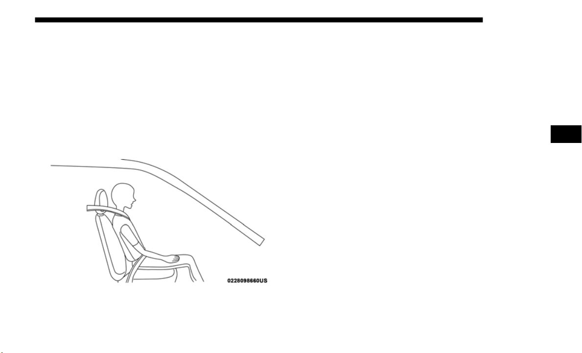
SAFETY 267
designed, it is important for the front passenger to be seated
properly and properly wearing the seat belt. Properly seated
passengers are:
• Sitting upright.
• Facing fo
rward.
• Sitting
in the center of the seat with their feet comfortably
on or n
ear the floor.
• Sitting with their back against the seat back and the seat
back in
an upright position.
Seated Properly
The OCS may deactivate the deployment of the Passenger
Advanced
Front Air Bag if the OCS estimates that:
• The front passenger seat is unoccupied or has very light
objects
in it.
• The front passenger seat is occupied by a rear-facing child
restrai
nt.
• The front passenger seat is occupied by a child, including
a child
seated in a forward-facing child restraint or booster
seat.
• The front passenger seat is occupied by a small passenger,
includi
ng a child or small adult.
• The front passenger is not properly seated or his or her
weight is
taken off of the seat for a period of time.
4

268 SAFETY
* When the front passenger seat is empty or when very light
objects are placed on the seat and the seat belt is unbuckled,
the Passenger Advanced Front Air Bag will not deploy even
though the PAD System Indicator Light is NOT illuminated.
** It is possible for a child to be classified as an adult,
allowing
the deployment of the Passenger Advanced Front
Air Bag. Never allow children to ride in the front passenger
seat and never install a child restraint system, including a
rear-facing child restraint, in the front passenger seat.
Passenger Air Bag Disable (PAD) System
Front Passenger
Seat Oc
cupant
Status
Front Passenger
Advanced
Air
Bag Disabled
Indicator Light
(“PAD”) Status
Front Passenger
Air Bag
Status
Unoccupied seat*
Unbuckle
d
NOT
ILLUMINATED
DEACTIVATED
Unoccupied
seat*Bu
ckled
“PASSENGER
AIR BAG OFF”
DEACTIVATED
Grocery bags,
heavy br
iefcases,
and other relatively
light objects
“PASSENGER
AIR BAG
OFF”
DEACTIVATED
Rear-facing child
restrai
nt**
“PASSENGER
AIR BAG OFF”
DEACTIVATED
Child, including a
child in a
forward-facing
child restraint or
booster seat**
“PASSENGER
AIR BAG OFF”
DEACTIVATED
Small adult
“PASSENGER
AIR BAG
OFF”
DEACTIVATED
Properly seated
adult
NOT
I
LLUMINATED
ACTIVATED
Passenger Air Bag Disable (PAD) System
Front Passenger
Seat Occupant
Status
Front Passenger
Advanced Air
Bag Disabled
Indicator Light
(“PAD”) Status
Front Passenger
Air Bag Status

SAFETY 269
Passenger Advanced Front Air Bag Disabled (PAD) Indi-
cator Light
The Passenger Advanced Front Air Bag Disabled (PAD)
Indicato
r Light (an amber light located on the overhead
sports bar) tells the driver and front passenger when the
Passenger Advanced Front Air Bag is deactivated. The PAD
Indicator light illuminates the words “PASSENGER AIR
BAG OFF” to show that the Passenger Advanced Front Air
Bag will not deploy during a collision. When the front
passenger seat is empty or when very light objects are placed
on the seat and the seat belt is unbuckled, the Passenger
Advanced Front Air Bag will not deploy even though the
PAD indicator light is NOT illuminated.
The PAD indicator light should not be illuminated when an
adult pa
ssenger is properly seated in the front passenger
seat. The driver and adult passenger should verify that the
PAD Indicator Light is not illuminated when an adult is
riding in the front passenger seat. If an adult is not seated
properly, the Passenger Advanced Front Air Bag may deac
-
tivate and the PAD Indicator Light will be illuminated.
The PAD Indicator Light should be illuminated and the
P
assenger
Advanced Front Air Bag should be deactivated for
most properly seated and restrained children in the
passenger seat and for most properly installed child restraint
systems. However, under certain conditions, even with a
properly installed child restraint system, the PAD Indicator
Light may not be illuminated, even though the Passenger
Advanced Front Air Bag is deactivated. This can occur if the
child restraint is lighter than the lightest weight necessary to
illuminate the PAD Indicator Light. NEVER assume the
Passenger Advanced Front Air Bag is deactivated unless the
PAD Indicator Light is illuminated with the words
“PASSENGER AIR BAG OFF.”
NOTE:
If the seat belt is buckled for an empty seat, the PAD Indi-
cator Light will illuminate.
WARNING!
• Never place a rear-facing child restraint in front of an
air bag.
A deploying passenger front air bag can cause
death or serious injury to a child 12 years or younger,
including a child in a rear-facing child restraint.
• Never install a rear-facing child restraint in the front
seat of
a vehicle. Only use a rear-facing child restraint
in the rear seat. If the vehicle does not have a rear seat,
do not transport a rear-facing child restraint in that
vehicle.
4

270 SAFETY
If The PAD Indicator Light Is Illuminated For An Adult
Passenger:
If an adult passenger is seated in the front passenger seat and
the PAD
Indicator Light is illuminated, the passenger may be
sitting improperly. Follow the steps below to allow the OCS
to detect the adult passenger’s seated weight to activate the
Passenger Advanced Front Air Bag:
1. Turn off the vehicle and have the adult passenger step out
of the
vehicle.
2. Remove any extra materials from the passenger seat, such
as cus
hions, pads, seat covers, seat massagers, blankets,
extra clothing, etc.
3. Place the seatback in the full upright position.
4. Have
the adult passenger sit in the center of the seat, with
the pa
ssenger’s feet comfortably on or near the floor, and
with their back against the seatback.
5. Restart the vehicle and have the passenger remain in this
seated
position for two to three minutes after restarting
the vehicle.
WARNING!
• If the PAD Indicator Light remains illuminated for an
adult
passenger, have an authorized dealer service the
air bag system immediately. Failure to do so may cause
serious injury or death. If the PAD Indicator Light is
illuminated with the words "PASSENGER AIR BAG
OFF," the Passenger Advanced Front Air Bag will not
deploy in the event of a collision.
• Never place a rear-facing child restraint in front of an
air ba
g. A deploying passenger front air bag can cause
death or serious injury to a child 12 years or younger,
including a child in a rear-facing child restraint.
• Never install a rear-facing child restraint in the front
seat of
a vehicle. Only use a rear-facing child restraint
in the rear seat. If the vehicle does not have a rear seat,
do not transport a rear-facing child restraint in that
vehicle.
• Children 12 years or younger should always ride
buckle
d up in the rear seat of a vehicle with a rear seat.

SAFETY 271
Lighter Weight Passengers (Including Small Adults)
When a lighter weight passenger, including a small adult,
occupie
s the passenger seat, the Passenger Advanced Front
Air Bag may be deactivated. Therefore, the Passenger
Advanced Front Air Bag may or may not be activated for a
lighter weight passenger, including a small adult
(depending on size) who is seated in the passenger seat. This
does not mean that the OCS is working improperly.
The driver and passenger must always use the PAD Indi-
cator Light as a determination of whether the Passenger
Advance
d Front Air Bag is activated or deactivated. If the
PAD Indicator Light is illuminated with the words
“PASSENGER AIR BAG OFF” when an adult is in the front
passenger seat, have the passenger reposition his or her body
in the seat until the PAD Indicator Light goes out.
If the PAD Indicator Light is illuminated with the words
“PASSEN
GER AIR BAG OFF” the Passenger Advanced
Front Air Bag will not inflate in the event of a collision.
Do Not Decrease OR Increase The Front Passenger’s
Seated
Weight On The Front Passenger Seat
The front passenger’s seated weight must be properly posi-
tioned on the front passenger seat. Failure to do so may result
i
n seri
ous injury or death. The OCS determines the most prob-
able classification of the occupant that it detects. The OCS will
d
etect
the front passenger’s decreased or increased seated
weight, which may result in deactivation or activation of the
Passenger Advanced Front Air Bag in a collision. This does not
mean that the OCS is working improperly. Decreasing the
front passenger’s seated weight on the front passenger seat
may result in deactivation of the Passenger Advanced Front
Air Bag causing serious injury or death. Increasing the front
passenger’s seated weight on the front passenger seat may
result in activation of the Passenger Advanced Front Air Bag.
Examples of improper front passenger seating include:
• The front passenger’s weight is transferred to another part
of the
vehicle (like the door, arm rest or instrument panel).
• The front passenger leans forward, sideways, or turns to
face t
he rear of the vehicle.
• The front passenger’s seatback is not in the full upright position.
• The fr
ont passenger carries or holds an object while seated
(e.g.,
backpack, box, etc.).
• Objects are lodged under the front passenger seat.
4
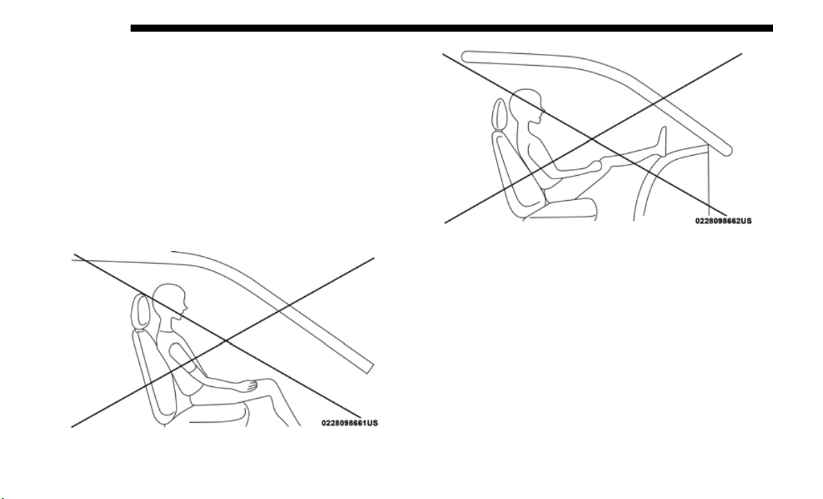
272 SAFETY
• Objects are lodged between the front passenger seat and
center console.
• Accessories that may change the seated weight on the front
passenge
r seat are attached to the front passenger seat.
• Anything that may decrease or increase the front
passenge
r’s seated weight.
The OCS determines the front passenger’s most probable
classifi
cation. If an occupant in the front passenger seat is
seated improperly, the occupant may provide an output
signal to the OCS that is different from the occupant’s prop
-
erly seated weight input, for example:
Not Seated Properly
Not Seated Properly
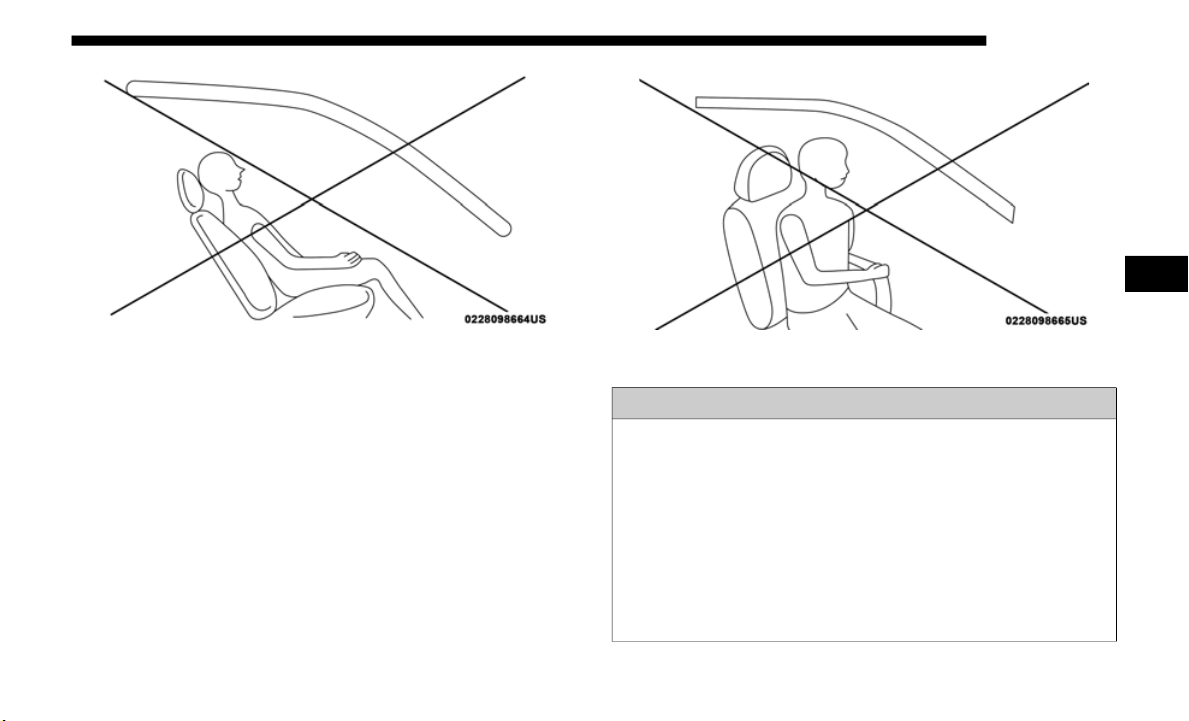
SAFETY 273
(Continued)
Not Seated Properly Not Seated Properly
WARNING!
• If a child restraint system, child, small teenager or adult in
the fro
nt passenger seat is seated improperly, the occupant
may provide an output signal to the OCS that is different
from the occupant’s properly seated weight input. This
may result in serious injury or death in a collision.
• Always wear your seat belt and sit properly, with the
seatbac
k in an upright position, your back against the
seatback, sitting upright, facing forward, in the center of
the seat, with your feet comfortably on or near the floor.
4

274 SAFETY
(Continued)
The Air Bag Warning Light will illuminate whenever the
OCS is unable to classify the front passenger seat status.
A malfunction in the OCS may affect the operation of the air
b
a
g system
. If the Air Bag Warning Light does not come
on, or stays on after you start the vehicle, or it comes on as
yo
u drive
, take the vehicle to an authorized dealer for service
immediately.
The passenger seat assembly contains critical OCS compo-
nents that may affect Passenger Advanced Front Air Bag
inflatio
n. In order for the OCS to properly classify the seated
weight of a front seat passenger, the OCS components must
function as designed. Do not make any modifications to the
front passenger seat components, assembly, or to the seat
cover. If the seat, trim cover, or cushion needs service for any
reason, take the vehicle to an authorized dealer. Only FCA
US LLC approved seat accessories may be used.
• Do not carry or hold any objects (e.g., backpacks, boxes,
etc.) w
hile seated in the front passenger seat. Holding
an object may provide an output signal to the OCS that
is different than the occupant’s properly seated weight
input, which may result in serious injury or death in a
collision.
WARNING!
• Ignoring the Air Bag Warning Light in your instrument
panel c
ould mean you won’t have the air bags to protect
you in a collision. If the light does not come on as a bulb
check when the ignition is first turned on, stays on after
you start the vehicle, or if it comes on as you drive, have an
authorized dealer service the air bag system immediately.
WARNING! (Continued)
• Placing an object on the floor under the front passenger
seat may prevent the OCS from working properly,
which may result in serious injury or death in a colli
-
sion. Do not place any objects on the floor under the
front pas
senger seat.
• If there is a fault present in the OCS, both the PAD Indi-
cator L
ight and the Air Bag Warning Light will illumi-
nate to show that the Passenger Advanced Front Air Bag
i
s deact
ivated. Should this occur, the Passenger
Advanced Front Air Bag will remain deactivated until the
fault is cleared. This indicates that you should take the
vehicle to an authorized dealer for service immediately.
WARNING! (Continued)

SAFETY 275
The following requirements must be strictly followed:
• Do not modify the front passenger seat assembly or
compon
ents in any way.
• Do not use prior or future model year seat covers or cush-
ions n
ot designated by FCA US LLC for the specific model
being re
paired. Always use the correct seat cover and
cushion specified for the vehicle.
• Do not replace the seat cover or cushion with an after-
market
seat cover or cushion.
• D
o not add a secondary seat cover or mat.
• At no
time should any Supplemental Restraint System
(SRS)
component or SRS related component or fastener be
modified or replaced with any part except those which are
approved by FCA US LLC.
WARNING!
• Unapproved modifications or service procedures to the
passen
ger seat assembly, its related components, seat
cover, or cushion may inadvertently change the air bag
deployment in case of a frontal collision. This could
result in death or serious injury to the front passenger
if the vehicle is involved in a collision. A modified
vehicle may not comply with required Federal Motor
Vehicle Safety Standards (FMVSS) and/or Canadian
Motor Vehicle Safety Standards (CMVSS).
• If it is necessary to modify the air bag system for
persons
with disabilities, contact an authorized dealer.
4
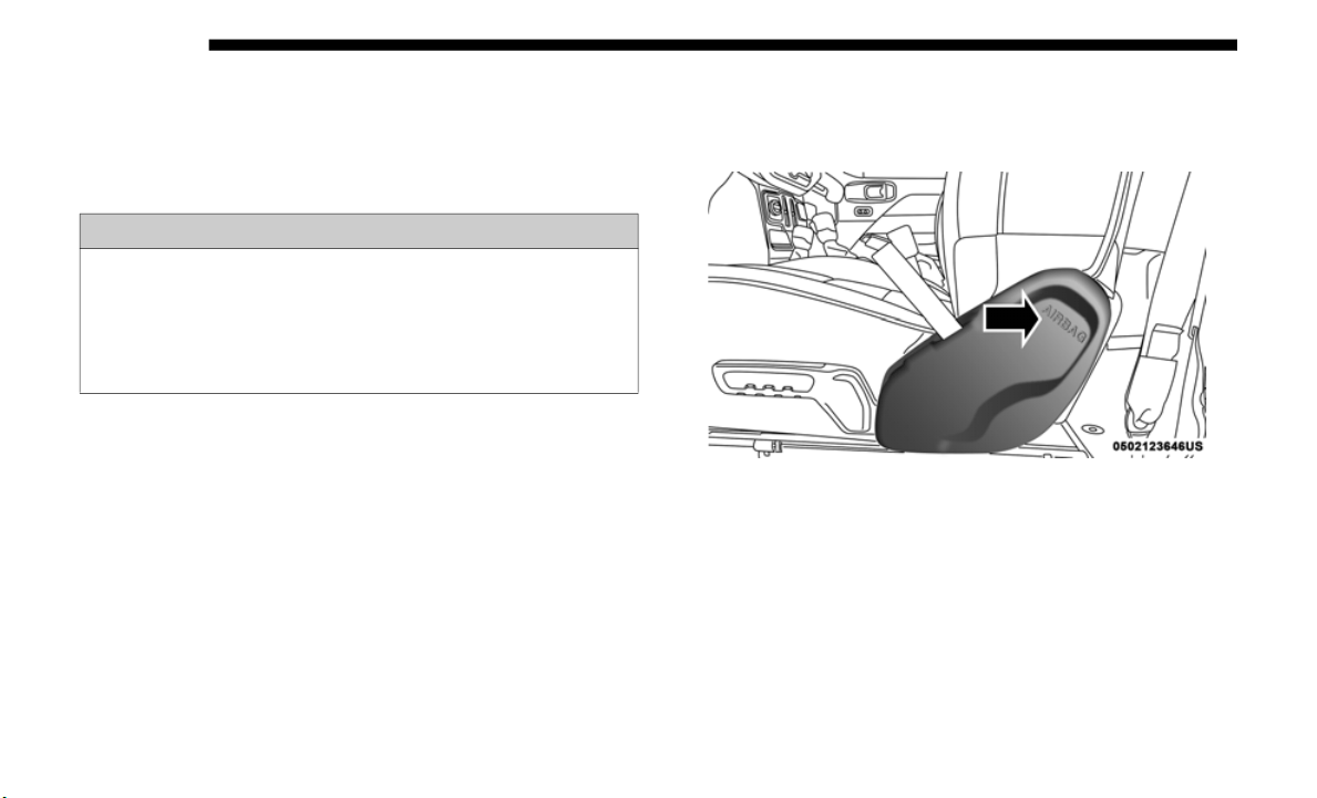
276 SAFETY
Knee Impact Bolsters
The Knee Impact Bolsters help protect the knees of the driver
and fron
t passenger, and position the front occupants for
improved interaction with the front air bags.
Supplemental Side Air Bags
Supplemental Seat-Mounted Side Air Bags (SABs)
This vehicle is equipped with Supplemental Seat-Mounted
Side Air
Bags (SABs).
Supplemental Seat-Mounted Side Air Bags (SABs) are
located
in the outboard side of the front seats. The SABs are
marked with a “SRS AIRBAG” or “AIRBAG” on a label or on
the seat trim on the outboard side of the seats.
The SABs may help to reduce the risk of occupant injury
during ce
rtain side impacts, in addition to the injury reduc-
tion potential provided by the seat belts and body structure.
Supplemental Seat-Mounted Side Air Bag Label
When the SAB deploys, it opens the seam on the outboard
s
ide of
the seatback’s trim cover. The inflating SAB deploys
through the seat seam into the space between the occupant
and the door. The SAB moves at a very high speed and with
such a high force that it could injure occupants if they are not
seated properly, or if items are positioned in the area where
the SAB inflates. Children are at an even greater risk of injury
from a deploying air bag.
WARNING!
• Do not drill, cut, or tamper with the knee impact
bolsters
in any way.
• Do not mount any accessories to the knee impact
bolsters
such as alarm lights, stereos, citizen band
radios, etc.

SAFETY 277
Side Impacts
The Side Air Bags are designed to activate in certain side
impacts
. The Occupant Restraint Controller (ORC) deter-
mines whether the deployment of the Side Air Bags in a
p
articu
lar impact event is appropriate, based on the severity
and type of collision. The side impact sensors aid the ORC in
determining the appropriate response to impact events. The
system is calibrated to deploy the Side Air Bags on the
impact side of the vehicle during impacts that require Side
Air Bag occupant protection. In side impacts, the Side Air
Bags deploy independently; a left side impact deploys the
left Side Air Bags only and a right-side impact deploys the
right Side Air Bags only. Vehicle damage by itself is not a
good indicator of whether or not Side Air Bags should have
deployed.
The Side Air Bags will not deploy in all side collisions,
includi
ng some collisions at certain angles, or some side
collisions that do not impact the area of the passenger
compartment. The Side Air Bags may deploy during angled
or offset frontal collisions where the front air bags deploy.
Side Air Bags are a supplement to the seat belt restraint
system.
Side Air Bags deploy in less time than it takes to
blink your eyes.
WARNING!
Do not use accessory seat covers or place objects between
you and t
he Side Air Bags; the performance could be
adversely affected and/or objects could be pushed into
you, causing serious injury.
WARNING!
• Occupants, including children, who are up against or
very clos
e to Side Air Bags can be seriously injured or
killed. Occupants, including children, should never
lean on or sleep against the door, side windows, or area
where the side air bags inflate, even if they are in an
infant or child restraint.
• Seat belts (and child restraints where appropriate) are
necess
ary for your protection in all collisions. They also
help keep you in position, away from an inflating Side
Air Bag. To get the best protection from the Side Air
Bags, occupants must wear their seat belts properly and
sit upright with their backs against the seats. Children
must be properly restrained in a child restraint or
booster seat that is appropriate for the size of the child.
4

278 SAFETY
NOTE:
Air bag covers may not be obvious in the interior trim, but
they will
open during air bag deployment.
Air Bag System Components
NOTE:
The Occupant Restraint Controller (ORC) monitors the
internal
circuits and interconnecting wiring associated with
electrical Air Bag System Components listed below:
• Occupant Restraint Controller (ORC)
• Air Bag
Warning Light
• Steerin
g Wheel and Column
• Instrum
ent Panel
• Knee Im
pact Bolsters
• Driver
and Front Passenger Air Bags
• Seat Be
lt Buckle Switch
• Supplem
ental Side Air Bags
• Front an
d Side Impact Sensors
• Seat Be
lt Pretensioners
• Seat Tr
ack Position Sensors
• Occupan
t Classification System
WARNING!
• Side Air Bags need room to inflate. Do not lean against
the door
or window. Sit upright in the center of the seat.
• Being too close to the Side Air Bags during deployment
could ca
use you to be severely injured or killed.
• Relying on the Side Air Bags alone could lead to more
severe
injuries in a collision. The Side Air Bags work
with your seat belt to restrain you properly. In some colli
-
sions, Side Air Bags won’t deploy at all. Always wear
your sea
t belt even though you have Side Air Bags.

SAFETY 279
If A Deployment Occurs
The front air bags are designed to deflate immediately after
deployme
nt.
NOTE:
Front and/or side air bags will not deploy in all collisions.
T
his do
es not mean something is wrong with the air bag
system.
If you do have a collision which deploys the air bags, any or
all of
the following may occur:
• The air bag material may sometimes cause abrasions and/
or skin
reddening to the occupants as the air bags deploy
and unfold. The abrasions are similar to friction rope burns
or those you might get sliding along a carpet or gymna
-
sium floor. They are not caused by contact with chemicals.
T
hey are
not permanent and normally heal quickly.
However, if you haven’t healed significantly within a few
days, or if you have any blistering, see your doctor imme
-
diately.
• A
s the air bags deflate, you may see some smoke-like parti-
cles.
The particles are a normal by-product of the process
that gen
erates the non-toxic gas used for air bag inflation.
These airborne particles may irritate the skin, eyes, nose, or
throat. If you have skin or eye irritation, rinse the area with
cool water. For nose or throat irritation, move to fresh air.
If the irritation continues, see your doctor. If these particles
settle on your clothing, follow the garment manufacturer’s
instructions for cleaning.
Do not drive your vehicle after the air bags have deployed. If
you are
involved in another collision, the air bags will not be
in place to protect you.
WARNING!
Deployed air bags and seat belt pretensioners cannot
protect
you in another collision. Have the air bags, seat
belt pretensioners, and the seat belt retractor assemblies
replaced by an authorized dealer immediately. Also,
have the Occupant Restraint Controller System serviced
as well.
4

280 SAFETY
NOTE:
• Air bag covers may not be obvious in the interior trim, but
they wil
l open during air bag deployment.
• After any collision, the vehicle should be taken to an
author
ized dealer immediately.
Enhanced Accident Response System
In the event of an impact, if the communication network
r
emains
intact, and the power remains intact, depending on
the nature of the event, the ORC will determine whether to
have the Enhanced Accident Response System perform the
following functions:
• Cut off fuel to the engine (If Equipped)
• Cut of
f battery power to the electric motor (If Equipped)
• Flash h
azard lights as long as the battery has power
• Turn o
n the interior lights, which remain on as long as the
batter
y has power or for 15 minutes from the intervention
of the
Enhanced Accident Response System.
• Unlock the power door locks.
Your v
ehicle may also be designed to perform any of these
other f
unctions in response to the Enhanced Accident
Response System:
• Turn off the Fuel Filter Heater, Turn off the HVAC Blower
Motor,
Close the HVAC Circulation Door
• Cut off battery power to the:
• Engine
• E
lect
ric Motor (if equipped)
• Elect
ric power steering
• Brake
booster
• Elect
ric park brake
• Autom
atic transmission gear selector
• Horn
• Fr
ont
wiper
• Headl
amp washer pump

SAFETY 281
NOTE:
After an accident, remember to cycle the ignition to the STOP
(OFF/LOCK)
position and remove the key from the ignition
switch to avoid draining the battery. Carefully check the
vehicle for fuel leaks in the engine compartment and on the
ground near the engine compartment and fuel tank before
resetting the system and starting the engine. If there are no
fuel leaks or damage to the vehicle electrical devices (e.g.
headlights) after an accident, reset the system by following
the procedure described below. If you have any doubt,
contact an authorized dealer.
Enhanced Accident Response System Reset Procedure
In order to reset the Enhanced Accident Response System
functio
ns after an event, the ignition switch must be changed
from ignition START or ON/RUN to ignition OFF. Carefully
check the vehicle for fuel leaks in the engine compartment
and on the ground near the engine compartment and fuel
tank before resetting the system and starting the engine.
Maintaining Your Air Bag System
WARNING!
• Modifications to any part of the air bag system could cause
it to
fail when you need it. You could be injured if the air
bag system is not there to protect you. Do not modify the
components or wiring, including adding any kind of
badges or stickers to the steering wheel hub trim cover or
the upper passenger side of the instrument panel. Do not
modify the front bumper, vehicle body structure, or add
aftermarket side steps or running boards.
• It is dangerous to try to repair any part of the air bag
system
yourself. Be sure to tell anyone who works on
your vehicle that it has an air bag system.
• Do not attempt to modify any part of your air bag
system.
The air bag may inflate accidentally or may not
function properly if modifications are made. Take your
vehicle to an authorized dealer for any air bag system
service. If your seat, including your trim cover and
cushion, needs to be serviced in any way (including
removal or loosening/tightening of seat attachment
bolts), take the vehicle to an authorized dealer. Only
manufacturer approved seat accessories may be used. If
it is necessary to modify the air bag system for persons
with disabilities, contact an authorized dealer.
4

282 SAFETY
Event Data Recorder (EDR)
This vehicle is equipped with an event data recorder (EDR).
The mai
n purpose of an EDR is to record, in certain crash or
near crash-like situations, such as an air bag deployment or
hitting a road obstacle, data that will assist in understanding
how a vehicle’s systems performed. The EDR is designed to
record data related to vehicle dynamics and safety systems
for a short period of time, typically 30 seconds or less. The
EDR in this vehicle is designed to record such data as:
• How various systems in your vehicle were operating;
• Whethe
r or not the driver and passenger safety belts were
buckled
/fastened;
• How far (if at all) the driver was depressing the accelerator
and/or
brake pedal; and,
• How fast the vehicle was traveling.
These
data can help provide a better understanding of the
circums
tances in which crashes and injuries occur.
NOTE:
EDR data are recorded by your vehicle only if a non-trivial
c
rash s
ituation occurs; no data are recorded by the EDR
under normal driving conditions and no personal data (e.g.,
name, gender, age, and crash location) are recorded.
However, other parties, such as law enforcement, could
combine the EDR data with the type of personally identi
-
fying data routinely acquired during a crash investigation.
To read data recorded by an EDR, special equipment is
require
d, and access to the vehicle or the EDR is needed. In
addition to the vehicle manufacturer, other parties, such as
law enforcement, that have the special equipment, can read
the information if they have access to the vehicle or the EDR.
Child Restraints
Everyone in your vehicle needs to be buckled up at all times,
including babies and children. Every state in the United
States, and every Canadian province, requires that small
children ride in proper restraint systems. This is the law, and
you can be prosecuted for ignoring it.
Children 12 years or younger should ride properly buckled
up in a
rear seat, if available. According to crash statistics,
children are safer when properly restrained in the rear seats
rather than in the front.

SAFETY 283
There are different sizes and types of restraints for children
from newborn size to the child almost large enough for an
adult safety belt. Always check the child seat Owner’s
Manual to make sure you have the correct seat for your child.
Carefully read and follow all the instructions and warnings
in the child restraint Owner’s Manual and on all the labels
attached to the child restraint.
Before buying any restraint system, make sure that it has a
label c
ertifying that it meets all applicable Safety Standards.
You should also make sure that you can install it in the
vehicle where you will use it.
NOTE:
• F
or additional information, refer to http:/
/www.nhtsa.gov/
parents-and-caregivers or call: 1–888–327–4236
• Canadi
an residents should refer to Transport Canada’s
website
for additional information: http://www.tc.gc.ca/
eng/motorvehiclesafety/safedrivers-child-
safety-index-53.htm
WARNING!
In a collision, an unrestrained child can become a
projecti
le inside the vehicle. The force required to hold
even an infant on your lap could become so great that
you could not hold the child, no matter how strong you
are. The child and others could be badly injured or
killed. Any child riding in your vehicle should be in a
proper restraint for the child’s size.
4

284 SAFETY
Summary Of Recommendations For Restraining Children In Vehicles
Child Size, Height, Weight Or Age
Recommended Type Of Child
Restrai
nt
Infants and Toddlers
Children who are two years old or
younger a
nd who have not reached the
height or weight limits of their child
restraint
Either an Infant Carrier or a Convertible
Child R
estraint, facing rearward in a
rear seat of the vehicle
Small Children
Children who are at least two years old
o
r who h
ave outgrown the height or
weight limit of their rear-facing child
restraint
Forward-Facing Child Restraint with a
five-po
int Harness, facing forward in a
rear seat of the vehicle
Larger Children
Children who have outgrown their
f
orward-
facing child restraint, but are
too small to properly fit the vehicle’s
seat belt
Belt Positioning Booster Seat and the
vehicle
seat belt, seated in a rear seat of
the vehicle
Children Too Large for Child Restraints
Children 12 years old or younger, who
h
ave ou
tgrown the height or weight
limit of their booster seat
Vehicle Seat Belt, seated in a rear seat of
the veh
icle

SAFETY 285
(Continued)
Infant And Child Restraints
Safety experts recommend that children ride rear-facing in
the veh
icle until they are two years old or until they reach
either the height or weight limit of their rear-facing child
restraint. Two types of child restraints can be used
rear-facing: infant carriers and convertible child seats.
The infant carrier is only used rear-facing in the vehicle. It is
recomme
nded for children from birth until they reach the
weight or height limit of the infant carrier. Convertible child
seats can be used either rear-facing or forward-facing in the
vehicle. Convertible child seats often have a higher weight
limit in the rear-facing direction than infant carriers do, so
they can be used rear-facing by children who have outgrown
their infant carrier but are still less than at least two years old.
Children should remain rear-facing until they reach the
highest weight or height allowed by their convertible child
seat.
Older Children And Child Restraints
Children who are two years old or who have outgrown their
rear-fa
cing convertible child seat can ride forward-facing in
the vehicle. Forward-facing child seats and convertible child
seats used in the forward-facing direction are for children
who are over two years old or who have outgrown the
rear-facing weight or height limit of their rear-facing
convertible child seat. Children should remain in a
forward-facing child seat with a harness for as long as
possible, up to the highest weight or height allowed by the
child seat.
All children whose weight or height is above the
forward-
facing limit for the child seat should use a belt-posi-
tioning booster seat until the vehicle’s seat belts fit properly.
I
f the
child cannot sit with knees bent over the vehicle’s seat
WARNING!
• Never place a rear-facing child restraint in front of an
air ba
g. A deploying passenger front air bag can cause
death or serious injury to a child 12 years or younger,
including a child in a rear-facing child restraint.
• Never install a rear-facing child restraint in the front
seat of a vehicle. Only use a rear-facing child restraint
in the rear seat. If the vehicle does not have a rear seat,
do not transport a rear-facing child restraint in that
vehicle.
WARNING! (Continued)
4

286 SAFETY
cushion while the child’s back is against the seatback, they
should use a belt-positioning booster seat. The child and
belt-positioning booster seat are held in the vehicle by the
seat belt.
Children Too Large For Booster Seats
Children who are large enough to wear the shoulder belt
comfort
ably, and whose legs are long enough to bend over
the front of the seat when their back is against the seatback,
should use the seat belt in a rear seat. Use this simple 5-step
test to decide whether the child can use the vehicle’s seat belt
alone:
1. Can the child sit all the way back against the back of the
vehicl
e seat?
2. Do the child’s knees bend comfortably over the front of
the ve
hicle seat – while the child is still sitting all the way
back?
3. Does the shoulder belt cross the child’s shoulder between
the ne
ck and arm?
4. Is the lap part of the belt as low as possible, touching the
child’s
thighs and not the stomach?
5. Can the child stay seated like this for the whole trip?
If the
answer to any of these questions was “no,” then the
child s
till needs to use a booster seat in this vehicle. If the
child is using the lap/shoulder belt, check seat belt fit peri
-
odically and make sure the seat belt buckle is latched. A
WARNING!
• Improper installation can lead to failure of an infant or
child
restraint. It could come loose in a collision. The
child could be badly injured or killed. Follow the child
restraint manufacturer’s directions exactly when
installing an infant or child restraint.
• After a child restraint is installed in the vehicle, do not
move the
vehicle seat forward or rearward because it
can loosen the child restraint attachments. Remove the
child restraint before adjusting the vehicle seat posi
-
tion. When the vehicle seat has been adjusted, reinstall
t
he chi
ld restraint.
• When your child restraint is not in use, secure it in the
vehicle
with the seat belt or LATCH anchorages, or
remove it from the vehicle. Do not leave it loose in the
vehicle. In a sudden stop or accident, it could strike the
occupants or seatbacks and cause serious personal
injury.

SAFETY 287
child’s squirming or slouching can move the belt out of posi-
tion. If the shoulder belt contacts the face or neck, move the
child c
loser to the center of the vehicle, or use a booster seat
to position the seat belt on the child correctly.
Recommendations For Attaching Child Restraints
WARNING!
Never allow a child to put the shoulder belt under an
arm or b
ehind their back. In a crash, the shoulder belt
will not protect a child properly, which may result in
serious injury or death. A child must always wear both
the lap and shoulder portions of the seat belt correctly.
Restraint Type
Combined Weight
of the Child +
Child Restraint
Use Any Attachment Method Shown With An “X” Below
LATCH – Lower
A
nchors
Only
Seat Belt Only
LATCH – Lower
A
nchors
+ Top
Tether Anchor
Seat Belt + Top
Tether
Anchor
Rear-Facing Child
Restrai
nt
Up to 65 lbs
(29.5 kg)
X X
Rear-Facing Child
Restrai
nt
More than 65 lbs
(29.5 kg)
X
Forward-Facing
Child R
estraint
Up to 65 lbs
(29.5 kg)
X X
Forward-Facing
Child R
estraint
More than 65 lbs
(29.5 kg)
X
4
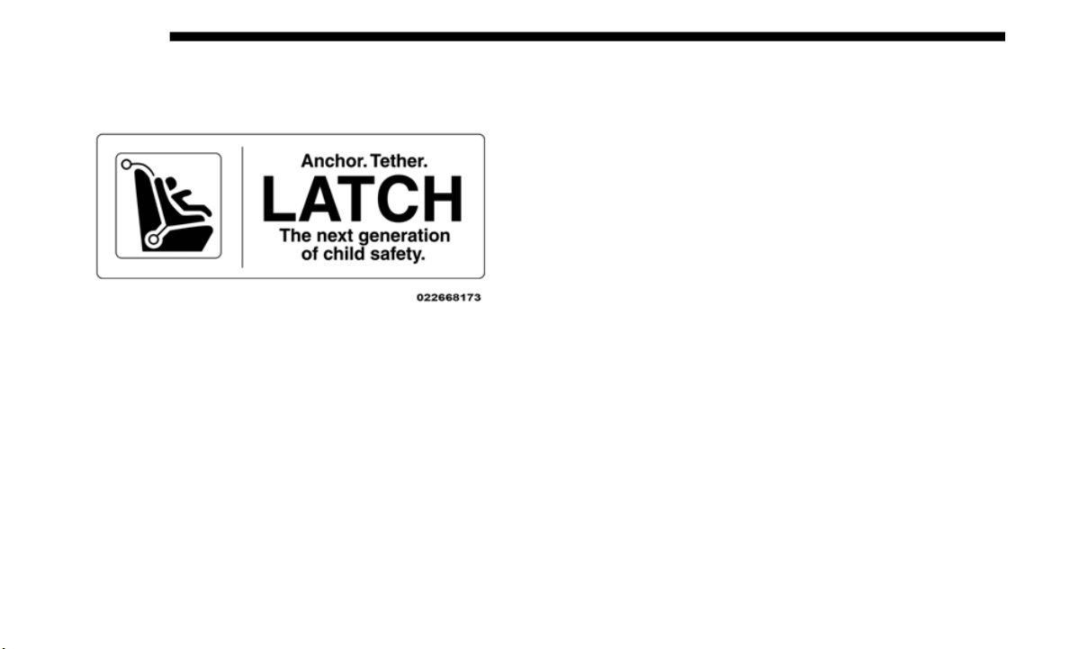
288 SAFETY
Lower Anchors And Tethers For CHildren (LATCH)
Restraint System
LATCH Label
Your vehicle is equipped with the child restraint anchorage
system called LATCH, which stands for Lower Anchors and
Tethers for CHildren. The LATCH system has three vehicle
anchor points for installing LATCH-equipped child seats.
There are two lower anchorages located at the back of the
seat cushion where it meets the seatback and one top tether
anchorage located behind the seating position. These anchor
-
ages are used to install LATCH-equipped child seats without
using the
vehicle’s seat belts. Some seating positions may
have a top tether anchorage but no lower anchorages. In
these seating positions, the seat belt must be used with the
top tether anchorage to install the child restraint. Please see
the following table for more information.
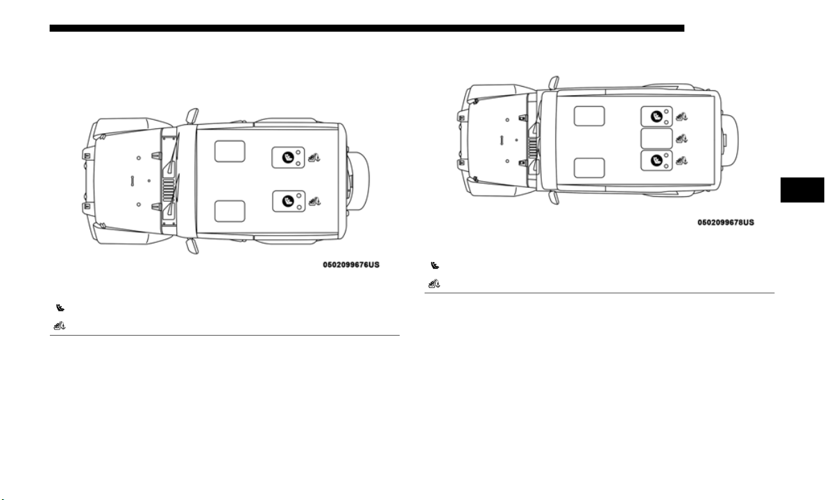
SAFETY 289
LATCH Positions For Installing Child Restraints In This
Vehicle
LATCH Positions (Two-Door Models)
LATCH Positions (Four-Door Models)
Lower Anchorage Symbol (2 Anchorages Per Seating Position)
Top Tether Anchorage Symbol
Lower Anchorage Symbol (2 Anchorages Per Seating Position)
Top Tether Anchorage Symbol
4

290 SAFETY
Frequently Asked Questions About Installing Child Restraints With LATCH
What is the weight limit (child’s weight
+ weight o
f the child restraint) for using
the LATCH anchorage system to attach
the child restraint?
65 lbs (29.5 kg)
Use the LATCH anchorage system until the combined weight
of the c hild and the child restraint is 65 lbs (29.5 kg). Use the
seat belt and tether anchor instead of the LATCH system once
the combined weight is more than 65 lbs (29.5 kg).
Can the LATCH anchorages and the
seat be
lt be used together to attach a
rear-facing or forward-facing child
restraint?
No
Do not use the seat belt when you use the LATCH
a
nchora
ge system to attach a rear-facing or
forward-facing child restraint.
Booster seats may be attached to the LATCH anchorages
if allo
wed by the booster seat manufacturer. See your
booster seat owner’s manual for more information.
Can a child seat be installed in the
center
position using the inner LATCH
lower anchorages?
Two Door Models –
No
Four Do
or Models –
Yes
Four D
oor Only: You can install child restraints with
flexibl
e lower anchors in the center position. The inner
anchorages are 18.5
inches (470 mm) apart. Do not install
child r
estraints with rigid lower anchors in the center
position.
See “Head Restraints” in “Getting To Know Your
Vehicle
” for further information.

SAFETY 291
NOTE:
If the folding, non-adjustable head restraint interferes with
the ins
tallation of the child restraint, the head restraint may
be folded and the child seat installed in front of it (Two-Door
Models).
Can two child restraints be attached
using a
common lower LATCH
anchorage?
No
Never “share” a LATCH anchorage with two or more
c
hild r
estraints. If the center position does not have
dedicated LATCH lower anchorages, use the seat belt to
install a child seat in the center position next to a child
seat using the LATCH anchorages in an outboard
position.
Can the rear-facing child restraint touch
the bac
k of the front passenger seat?
Yes
The child seat may touch the back of the front passenger
seat if
the child restraint manufacturer also allows
contact. See your child restraint owner’s manual for more
information.
Can the rear head restraints be
removed
?
Two Door Models –
No
Four Do
or Models –
Yes
Two Do
or Models — None
Four Door — The center head restraint can be removed if
i
t inte
rferes with the installation of the child restraint.
See “Head Restraints” in “Getting To Know Your
Vehicle
” for further information.
Frequently Asked Questions About Installing Child Restraints With LATCH
4
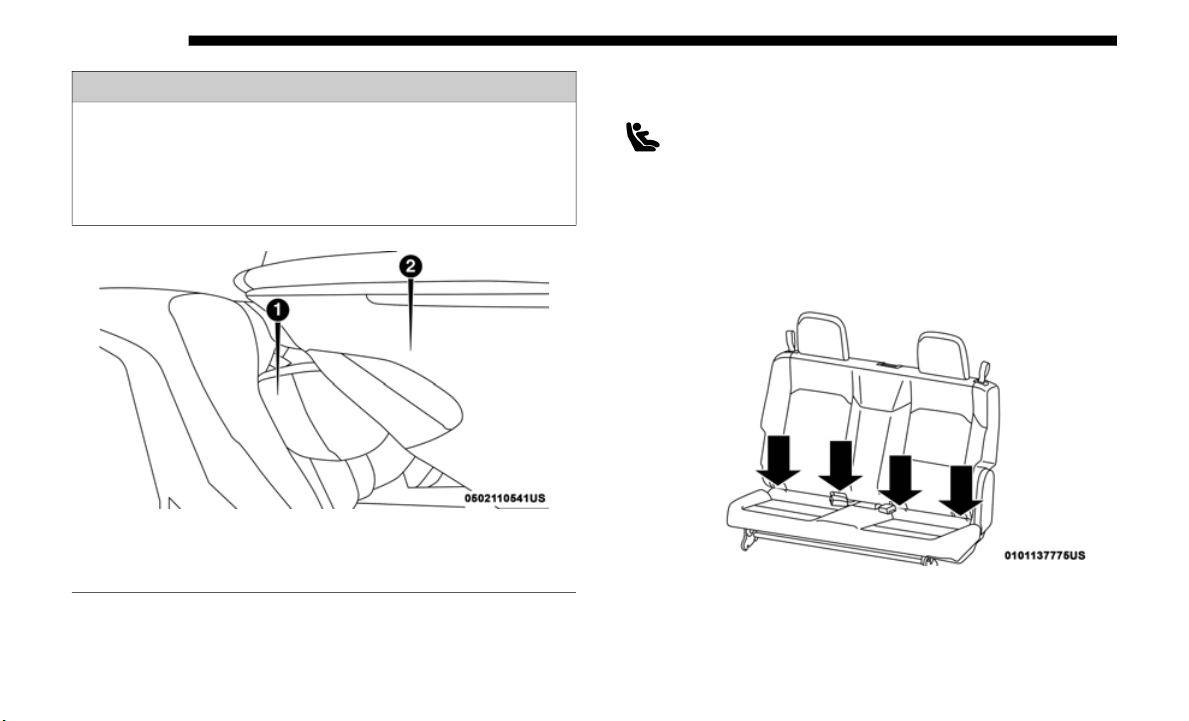
292 SAFETY
Car Seat With Head Restraint Folded
Locating The LATCH Anchorages
The lower anchorages are round bars that are found
at the rear of the seat cushion where it meets the seat-
back. They are just visible when you lean into the
r
ear sea
t to install the child restraint. You will easily feel
them if you run your finger along the gap between the seat
-
back and seat cushion. If your vehicle is equipped with
anchorage
symbols on the seatback, they will be located just
above the lower anchorages.
LATCH Anchorages (Two-Door Models)
WARNING!
Always make sure the head restraint is in its upright
position w
hen the seat is to be used by an occupant who
is not in a child restraint. Sitting in a seat with the head
restraint in its lowered position could result in serious
injury or death in a collision.
1 — Folded Headrest
2 — Child Restraint
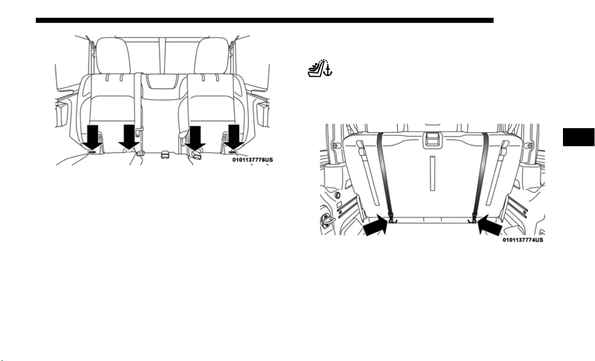
SAFETY 293
LATCH Anchorages (Four-Door Models)
Locating The Upper Tether Anchorages
Two-Door Models:
There are tether strap anchorages behind each rear
seating
position located on the back of the seat, near
the floor.
Tether Strap Anchorages (Two-Door Models)
4
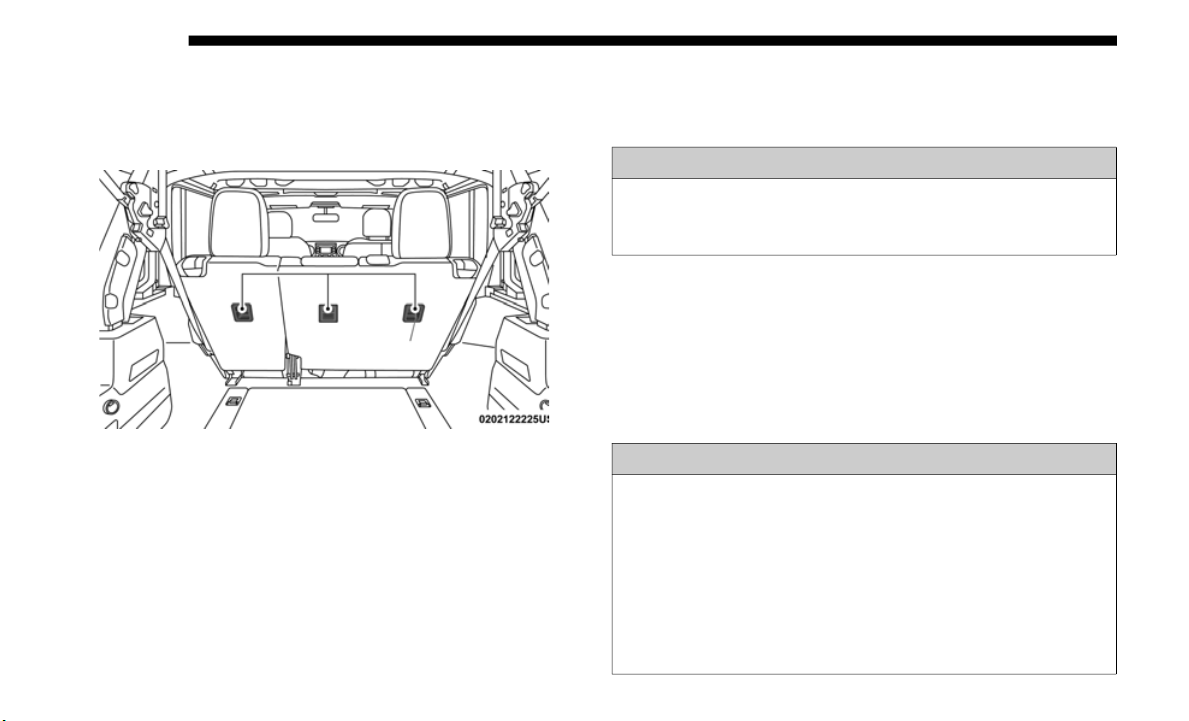
294 SAFETY
Four-Door Models:
There are tether strap anchorages behind each rear seating
position
located on the back of the seat.
Tether Strap Anchorages (Four-Door Models)
LATCH-compatible child restraint systems will be equipped
with a ri
gid bar or a flexible strap on each side. Each will
have a hook or connector to attach to the lower anchorage
and a way to tighten the connection to the anchorage.
Forward-facing child restraints and some rear-facing child
restraints will also be equipped with a tether strap. The
tether strap will have a hook at the end to attach to the top
tether anchorage and a way to tighten the strap after it is
attached to the anchorage.
Center Seat LATCH
Two-Door Models:
Four-Door Models:
Do not install child restraints with rigid lower attachments in
the cent
er seating position. Only install this type of child
restraint in the outboard seating positions. Child restraints
with flexible, webbing mounted lower attachments can be
installed in any rear seating position.
WARNING!
This vehicle does not have a center seating position. Do
not use t
he center lower LATCH anchorages to install a
child seat in the center of the back seat.
WARNING!
Never use the same lower anchorage to attach more than one
child re
straint. If you are installing LATCH-compatible
child restraints next to each other, you must use the seat belt
for the center position. You can then use either the LATCH
anchors or the vehicle’s seat belt for installing child seats in
the outboard positions.
Please refer to “Installing The LATCH-Compatible Child
Restrain
t System” for typical installation instructions.

SAFETY 295
Always follow the directions of the child restraint manu-
facturer when installing your child restraint. Not all child
restrai
nt systems will be installed as described here.
To Install A LATCH-Compatible Child Restraint
If the selected seating position has a Switchable Automatic
L
o
cking
Retractor (ALR) seat belt, stow the seat belt,
following the instructions below. See the section “Installing
Child Restraints Using the Vehicle Seat Belt” to check what
type of seat belt each seating position has.
1. Loosen the adjusters on the lower straps and on the tether
strap
of the child seat so that you can more easily attach
the hooks or connectors to the vehicle anchorages.
2. Place the child seat between the lower anchorages for that
seatin
g position. For some second row seats, you may
need to recline the seat and / or raise the head restraint (if
adjustable) to get a better fit. If the rear seat can be moved
forward and rearward in the vehicle, you may wish to
move it to its rear-most position to make room for the
child seat. You may also move the front seat forward to
allow more room for the child seat.
3. Attach the lower hooks or connectors of the child restraint
to the
lower anchorages in the selected seating position.
4. If the child restraint has a tether strap, connect it to the top
tether
anchorage. See the section “Installing Child
Restraints Using the Top Tether Anchorage” for direc
-
tions to attach a tether anchor.
5. T
ighten all of the straps as you push the child restraint
rearwar
d and downward into the seat. Remove slack in
the straps according to the child restraint manufacturer’s
instructions.
6. Test that the child restraint is installed tightly by pulling
back an
d forth on the child seat at the belt path. It should
not move more than 1
inch (25.4 mm) in any direction.
4

296 SAFETY
How To Stow An Unused Switchable-ALR (ALR) Seat Belt:
When using the LATCH attaching system to install a child
restrai
nt, stow all ALR seat belts that are not being used by
other occupants or being used to secure child restraints. An
unused belt could injure a child if they play with it and acci-
dentally lock the seat belt retractor. Before installing a child
restrai
nt using the LATCH system, buckle the seat belt behind
the child restraint and out of the child’s reach. If the buckled
seat belt interferes with the child restraint installation, instead
of buckling it behind the child restraint, route the seat belt
through the child restraint belt path and then buckle it. Do not
lock the seat belt. Remind all children in the vehicle that the
seat belts are not toys and that they should not play with them.
Installing Child Restraints Using The Vehicle Seat Belt
Child restraint systems are designed to be secured in vehicle
seats b
y lap belts or the lap belt portion of a lap/shoulder belt.
The seat belts in the passenger seating positions are
equippe
d with a Switchable Automatic Locking Retractor
(ALR) that is designed to keep the lap portion of the seat belt
tight around the child restraint so that it is not necessary to
use a locking clip. The ALR retractor can be “switched” into
a locked mode by pulling all of the webbing out of the
retractor and then letting the webbing retract back into the
retractor. If it is locked, the ALR will make a clicking noise
while the webbing is pulled back into the retractor.
Refer to the “Automatic Locking Mode” description in
“Switcha
ble Automatic Locking Retractors (ALR)” under
“Occupant Restraint Systems” for additional information on
ALR.
WARNING!
• Improper installation of a child restraint to the LATCH
anchor
ages can lead to failure of the restraint. The child
could be badly injured or killed. Follow the child restraint
manufacturer’s directions exactly when installing an
infant or child restraint.
• Child restraint anchorages are designed to withstand
only thos
e loads imposed by correctly-fitted child
restraints. Under no circumstances are they to be used
for adult seat belts, harnesses, or for attaching other
items or equipment to the vehicle.
WARNING!
• Improper installation or failure to properly secure a
child
restraint can lead to failure of the restraint. The
child could be badly injured or killed.
• Follow the child restraint manufacturer’s directions
exactl
y when installing an infant or child restraint.
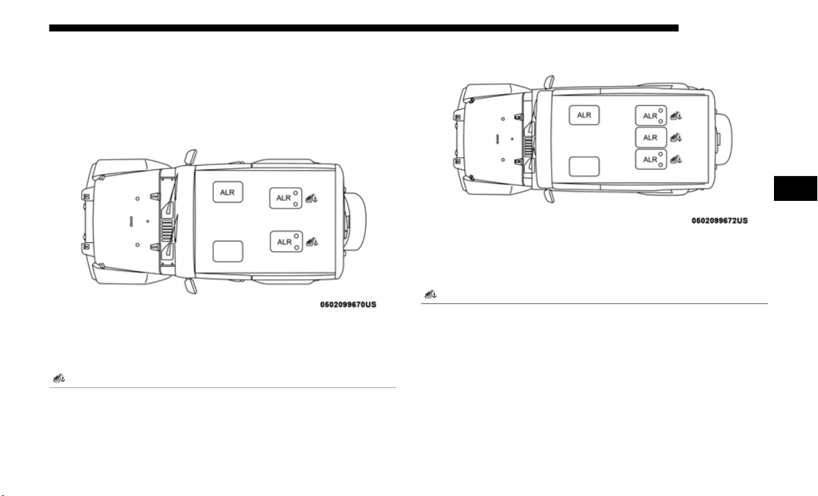
SAFETY 297
Please see the table below and the following sections for
more information.
Lap/Shoulder Belt Systems For Installing Child
Restraints In Th
is Vehicle
Automatic Locking Retractor Locations
(Two-Door M
odels)
Automatic Locking Retractor Locations
(Four-Door M
odels)
ALR = Switchable Automatic Locking Retractor
Top Tether Anchorage Symbol
ALR = Switchable Automatic Locking Retractor
Top Tether Anchorage Symbol
4

298 SAFETY
NOTE:
If the folding, non-adjustable head restraint interferes with
the ins
tallation of the child restraint, the head restraint may
be folded and the child seat installed in front of it (Two-Door
Models).
Frequently Asked Questions About Installing Child Restraints With Seat Belts
What is the weight limit (child’s weight
+ weight o
f the child restraint) for using
the Tether Anchor with the seat belt to
attach a forward facing child restraint?
Weight limit of the
Child R
estraint
Always use the tether anchor when using the seat belt to
install
a forward facing child restraint, up to the
recommended weight limit of the child restraint.
Can the rear-facing child restraint
touch t
he back of the front passenger
seat?
Yes
Contact between the front passenger seat and the child
restraint is allowed, if the child restraint manufacturer
also allows contact.
Can the rear head restraints be
removed
?
Two Door Models – No
Four Door Models –
Y
es
Two Do
or — None
Four Door — The center head restraint can be removed if
i
t inte
rferes with the installation of the child restraint.
See “Head Restraints” in “Getting To Know Your
Vehicle
” for further information.
Can the buckle stalk be twisted to
tighten
the seat belt against the belt
path of the child restraint?
No
Do not twist the buckle stalk in a seating position with an
A
LR ret
ractor.
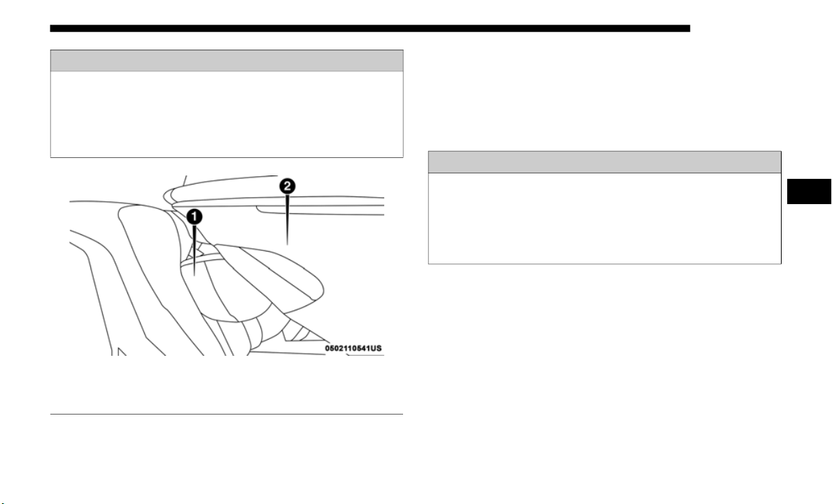
SAFETY 299
Car Seat With Head Restraint Folded
Installing A Child Restraint With A Switchable Automatic
Locking Retrac
tor (ALR):
Child restraint systems are designed to be secured in vehicle
seats by
lap belts or the lap belt portion of a lap/shoulder
belt.
1. Place the child seat in the center of the seating position.
For some
second row seats, you may need to recline the
seat and/or raise the head restraint (if adjustable) to get a
better fit. If the rear seat can be moved forward and rear
-
ward in the vehicle, you may wish to move it to its
r
ear-mos
t position to make room for the child seat. You
may also move the front seat forward to allow more room
for the child seat.
WARNING!
Always make sure the head restraint is in its upright
position w
hen the seat is to be used by an occupant who
is not in a child restraint. Sitting in a seat with the head
restraint in its lowered position could result in serious
injury or death in a collision.
1 — Folded Headrest
2 — Child Restraint
WARNING!
• Improper installation or failure to properly secure a
child r
estraint can lead to failure of the restraint. The
child could be badly injured or killed.
• Follow the child restraint manufacturer’s directions
exactly
when installing an infant or child restraint.
4

300 SAFETY
2. Pull enough of the seat belt webbing from the retractor to
pass it through the belt path of the child restraint. Do not
twist the belt webbing in the belt path.
3. Slide the latch plate into the buckle until you hear a
“click.
”
4. Pull on the webbing to make the lap portion tight against
the ch
ild seat.
5. To lock the seat belt, pull down on the shoulder part of
the be
lt until you have pulled all the seat belt webbing out
of the retractor. Then, allow the webbing to retract back
into the retractor. As the webbing retracts, you will hear
a clicking sound. This means the seat belt is now in the
Automatic Locking mode.
6. Try to pull the webbing out of the retractor. If it is locked,
you sho
uld not be able to pull out any webbing. If the
retractor is
not
locked, repeat step 5.
7. Finally, pull up on any excess webbing to tighten the lap
portion around the child restraint while you push the
child restraint rearward and downward into the vehicle
seat.
8. If the child restraint has a top tether strap and the seating
positi
on has a top tether anchorage, connect the tether
strap to the anchorage and tighten the tether strap. See the
section “Installing Child Restraints Using the Top Tether
Anchorage” for directions to attach a tether anchor.
9. Test that the child restraint is installed tightly by pulling
back an
d forth on the child seat at the belt path. It should
not move more than 1
inch (25.4 mm) in any direction.
Any seat belt system will loosen with time, so check the belt
occasio
nally, and pull it tight if necessary.
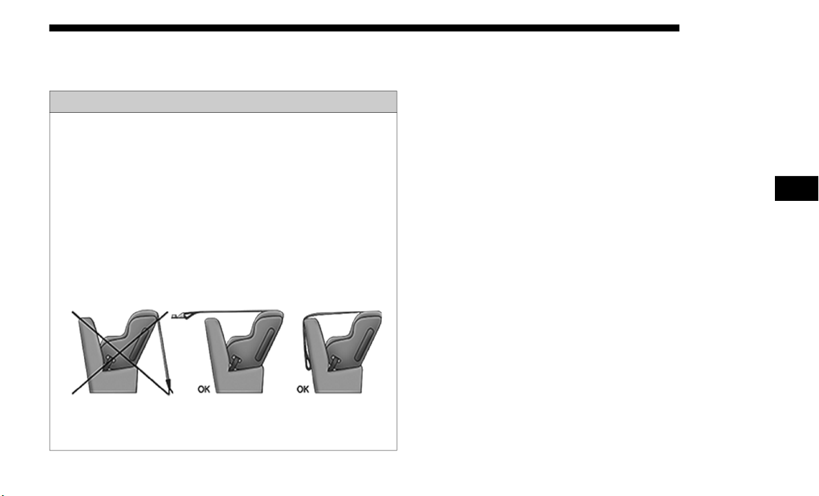
SAFETY 301
Installing Child Restraints Using The Top Tether
Anchorage
1. Look behind the seating position where you plan to install
the chi ld restraint to find the tether anchorage. You may
need to move the seat forward to provide better access to
the tether anchorage. If there is no top tether anchorage for
that seating position, move the child restraint to another
position in the vehicle if one is available.
2. Route the tether strap to provide the most direct path for
the str
ap between the anchor and the child seat. If your
vehicle is equipped with adjustable rear head restraints,
raise the head restraint, and where possible, route the
tether strap under the head restraint and between the two
posts. If not possible, lower the head restraint and pass
the tether strap around the outboard side of the head
restraint.
WARNING!
Do not attach a tether strap for a rear-facing car seat to
any locati
on in front of the car seat, including the seat
frame or a tether anchorage. Only attach the tether strap
of a rear-facing car seat to the tether anchorage that is
approved for that seating position, located behind the
top of the vehicle seat. See the section “Lower Anchors
and Tethers for CHildren (LATCH) Restraint System”
for the location of approved tether anchorages in your
vehicle.
4
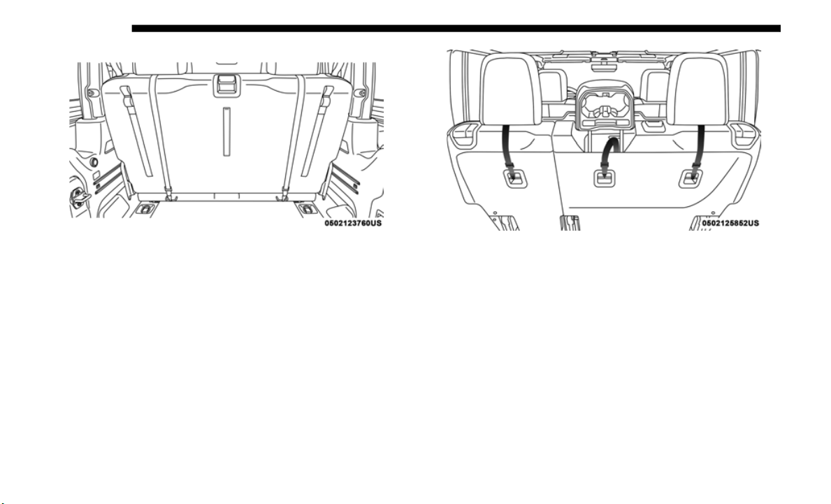
302 SAFETY
Tether Strap Mounting (Two-Door Models) Tether Strap Mounting (Four-Door Models With Center
Armrest)
3. A
ttach the tether strap hook of the child restraint to the
t
op tet
her anchorage as shown in the diagram.
4. Remove slack in the tether strap according to the child
restrai
nt manufacturer’s instructions.
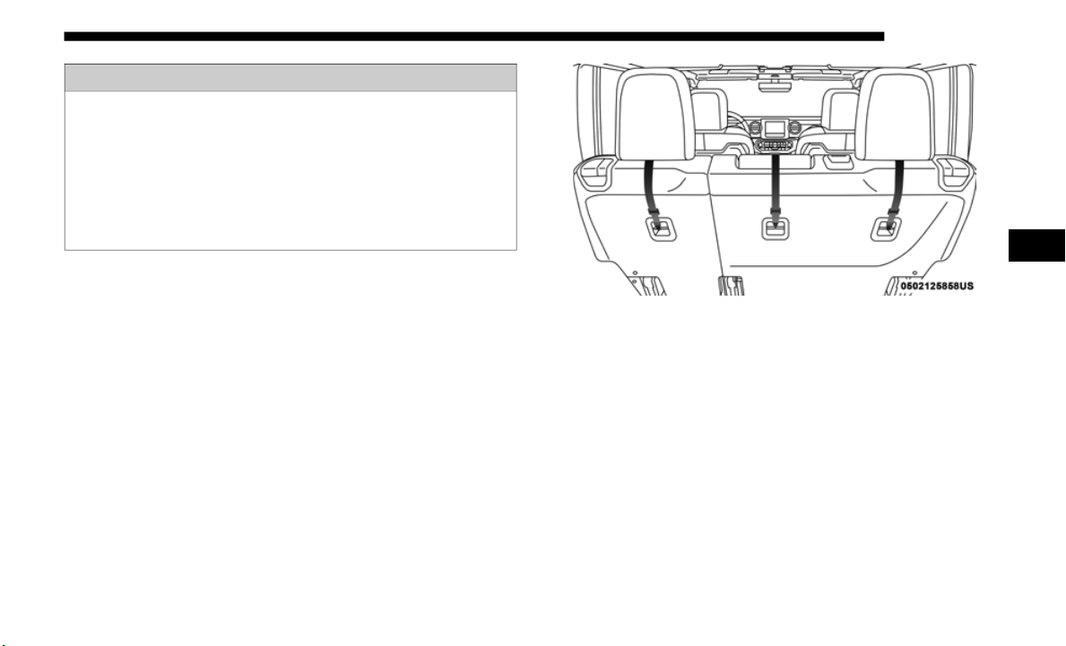
SAFETY 303
Center Tether Attachment — Four-Door Without Center
Armrest
1. If adjustable, lower the adjustable center head restraint to
the ful
l down position.
2. Route the tether strap over the seatback and head
restrai
nt.
Tether Strap Mounting (Four-Door Models Without
Center A
rmrest)
3. A
ttach the tether strap hook of the child restraint to the
c
enter
tether anchorage located on the back of the seat.
4. Remove slack in the tether strap according to the child
restrai
nt manufacturer’s instructions.
WARNING!
• An incorrectly anchored tether strap could lead to
increas
ed head motion and possible injury to the child.
Use only the anchorage position directly behind the
child seat to secure a child restraint top tether strap.
• If your vehicle is equipped with a split rear seat, make
sure th
e tether strap does not slip into the opening
between the seatbacks as you remove slack in the strap.
4

304 SAFETY
Transporting Pets
Air Bags deploying in the front seat could harm your pet. An
unrestrained pet will be thrown about and possibly injured,
or injure a passenger during panic braking or in a collision.
Pets should be restrained in the rear seat (if equipped) in pet
harness
es or pet carriers that are secured by seat belts.
SAFETY TIPS
Transporting Passengers
NEVER TRANSPORT PASSENGERS IN THE CARGO AREA.
Exhaust Gas
WARNING!
• Do not leave children or animals inside parked vehicles
in hot
weather. Interior heat build-up may cause
serious injury or death.
• It is extremely dangerous to ride in a cargo area, inside or
outsid
e of a vehicle. In a collision, people riding in these
areas are more likely to be seriously injured or killed.
• Do not allow people to ride in any area of your vehicle
that i
s not equipped with seats and seat belts.
• Be sure everyone in your vehicle is in a seat and using
a seat
belt properly.
WARNING!
Exhaust gases can injure or kill. They contain carbon
monoxide
(CO), which is colorless and odorless.
Breathing it can make you unconscious and can
eventually poison you. To avoid breathing (CO), follow
these safety tips:
• Do not run the engine in a closed garage or in confined
areas
any longer than needed to move your vehicle in or
out of the area.
• If you are required to drive with the trunk/liftgate/rear
doors ope
n, make sure that all windows are closed and
the climate control BLOWER switch is set at high
speed. DO NOT use the recirculation mode.
• If it is necessary to sit in a parked vehicle with the
engine
running, adjust your heating or cooling controls
to force outside air into the vehicle. Set the blower at
high speed.

SAFETY 305
The best protection against carbon monoxide entry into the
vehicle body is a properly maintained engine exhaust
system.
Whenever a change is noticed in the sound of the exhaust
system,
when exhaust fumes can be detected inside the
vehicle, or when the underside or rear of the vehicle is
damaged, have a competent mechanic inspect the complete
exhaust system and adjacent body areas for broken,
damaged, deteriorated, or mispositioned parts. Open seams
or loose connections could permit exhaust fumes to seep into
the passenger compartment. In addition, inspect the exhaust
system each time the vehicle is raised for lubrication or oil
change. Replace as required.
Safety Checks You Should Make Inside The Vehicle
Seat Belts
Inspect the seat belt system periodically, checking for cuts,
frays, a
nd loose parts. Damaged parts must be replaced
immediately. Do not disassemble or modify the system.
Front seat belt assemblies must be replaced after a collision.
Rear se
at belt assemblies must be replaced after a collision if
they have been damaged (i.e., bent retractor, torn webbing,
etc.). If there is any question regarding seat belt or retractor
condition, replace the seat belt.
Air Bag Warning Light
The Air Bag warning light will turn on for four to eight
seconds as a bulb check when the ignition switch is first
turned
to ON/RUN. If the light is either not on during
starting, stays on, or turns on while driving, have the system
inspected at an authorized dealer as soon as possible. This
light will illuminate with a single chime when a fault with
the Air Bag Warning Light has been detected, it will stay on
until the fault is removed. If the light comes on intermittently
or remains on while driving, have an authorized dealer
service the vehicle immediately. Refer to “Occupant
Restraint Systems” in “Safety” for further information.
Defroster
Check operation by selecting the defrost mode and place the
blower c
ontrol on high speed. You should be able to feel the
air directed against the windshield. See an authorized dealer
for service if your defroster is inoperable.
Floor Mat Safety Information
Always use floor mats designed to fit your vehicle. Only use
a floor
mat that does not interfere with the operation of the
pedal assemblies. Only use a floor mat that is securely
attached using the floor mat fasteners so it cannot slip out of
position and interfere with the pedal assemblies or impair
safe operation of your vehicle in other ways.
4

306 SAFETY
(Continued)
(Continued)
WARNING!
An improperly attached, damaged, folded, or stacked
floor mat,
or damaged floor mat fasteners may cause
your floor mat to interfere with the accelerator, brake, or
clutch pedals and cause a loss of vehicle control. To
prevent SERIOUS INJURY or DEATH:
• ALWAYS securely attach your floor
mat using the
floor mat fasteners. DO NOT install your floor mat
upside d
own or turn your floor mat over. Lightly pull to
confirm mat is secured using the floor mat fasteners on
a regular basis.
• ALWAYS REMOVE THE EXISTING FLOOR MAT
FROM THE
VEHICLE before installing any other
floor mat. NEVER install or stack an additional floor
m
at on top
of an existing floor mat.
• ONLY install floor mats designed to fit your vehicle.
NEVER i
nstall a floor mat that cannot be properly
attached and secured to your vehicle. If a floor mat
needs to be replaced, only use a FCA approved floor
mat for the specific make, model, and year of your
vehicle.
• ONLY use the driver’s side floor mat on the driver’s
side floor area. To check for interference, with the
vehicle properly parked with the engine off, fully
depress the accelerator, the brake, and the clutch pedal
(if present) to check for interference. If your floor mat
interferes with the operation of any pedal, or is not
secure to the floor, remove the floor mat from the
vehicle and place the floor mat in your trunk.
• ONLY use the passenger’s side floor mat on the
passenger’s side floor area.
• ALWAYS make sure objects cannot fall or slide into the
driver’s
side floor area when the vehicle is moving.
Objects can become trapped under accelerator, brake,
or clutch pedals and could cause a loss of vehicle
control.
• NEVER place any objects under the floor mat (e.g.,
towels,
keys, etc.). These objects could change the posi-
tion of the floor mat and may cause interference with
t
he acce
lerator, brake, or clutch pedals.
WARNING! (Continued)

SAFETY 307
Periodic Safety Checks You Should Make Outside
The Vehicle
Tires
Examine tires for excessive tread wear and uneven wear
pattern
s. Check for stones, nails, glass, or other objects
lodged in the tread or sidewall. Inspect the tread for cuts and
cracks. Inspect sidewalls for cuts, cracks, and bulges. Check
the wheel nuts for tightness. Check the tires (including
spare) for proper cold inflation pressure.
Lights
Have s
omeone observe the operation of brake lights and
exterio
r lights while you work the controls. Check turn
signal and high beam indicator lights on the instrument
panel.
Door Latches
Check for proper closing, latching, and locking.
Fluid Leaks
Check area under vehicle after overnight parking for fuel,
coolant
, oil, or other fluid leaks. Also, if gasoline fumes are
detected or if fuel, or brake fluid leaks are suspected. The
cause should be located and corrected immediately.
• If the vehicle carpet has been removed and re-installed,
always
properly attach carpet to the floor and check the
floor mat fasteners are secure to the vehicle carpet.
Fully depress each pedal to check for interference with
the accelerator, brake, or clutch pedals then re-install
the floor mats.
• It is recommended to only use mild soap and water to
clean
your floor mats. After cleaning, always check
your floor mat has been properly installed and is
secured to your vehicle using the floor mat fasteners by
lightly pulling mat.
WARNING! (Continued)
4

308
STARTING AND OPERATING
STARTING THE ENGINE
Before starting your vehicle, adjust your seat, adjust both
inside and outside mirrors, and fasten your seat belts.
Manual Transmission — If Equipped
Apply the parking brake, place the gear selector in
NEUTRAL, and press the clutch pedal before starting the
vehicle. This vehicle is equipped with a clutch interlocking
ignition system. It will not start unless the clutch pedal is
pressed to the floor.
Four-Wheel Drive Models Only
In 4L mode, this vehicle will start regardless of whether or
not the
clutch pedal is pressed to the floor. This feature
enhances off-road performance by allowing the vehicle to
start when in 4L without having to press the clutch pedal.
The “4WD Low Indicator Light” will illuminate when the
transfer case has been shifted into this mode.
WARNING!
• When exiting the vehicle, always remove the key fob
from th
e ignition and lock your vehicle.
• Never leave children alone in a vehicle, or with access
to an u
nlocked vehicle.
• Allowing children to be in a vehicle unattended is
dangerou
s for a number of reasons. A child or others
could be seriously or fatally injured. Children should
be warned not to touch the parking brake, brake pedal
or the gear selector.
• Do not leave the key fob in or near the vehicle, or in a
location
accessible to children. A child could operate
power windows, other controls, or move the vehicle.
• Do not leave children or animals inside parked vehicles
in hot
weather. Interior heat build-up may cause
serious injury or death.

STARTING AND OPERATING 309
Automatic Transmission — If Equipped
Start the vehicle with the gear selector in the PARK position
(vehicle can also be started in NEUTRAL). Apply the brake
before shifting to any driving range.
Normal Starting
To Turn On The Engine Using The ENGINE START/STOP
Button
1. The transmission must be in PARK or NEUTRAL.
2. Pres
s and hold the brake pedal while pushing the
ENGINE
START/STOP button once.
3. The system takes over and attempts to start the vehicle. If
the ve
hicle fails to start, the starter will disengage auto-
matically after 10 seconds.
4. I
f you wish to stop the cranking of the engine prior to the
engine
starting, push the button again.
NOTE:
Normal starting of either a cold or a warm engine is obtained
without
pumping or pressing the accelerator pedal.
To Turn Off The Engine Using ENGINE START/STOP
Button
1. P
lace the gear selector in PARK, then push and release the
ENGINE
START/STOP button.
2. The ignition will return to the OFF mode.
3. If t
he gear selector is not in PARK (with vehicle stopped)
and th
e ENGINE START/STOP button is pushed once,
the transmission will automatically select PARK and the
engine will turn off, however the ignition will remain in
the ACC mode (NOT the OFF mode). Never leave a
vehicle out of the PARK position, or it could roll.
4. If the gear selector is in NEUTRAL, and the vehicle speed
is bel
ow 5 mph (8 km/h), pushing the START/STOP
button
once will turn the engine off. The ignition will
remain in the ACC mode.
5. If the vehicle speed is above 5 mph (
8 km/h), the
ENGINE START/STOP button must be held for two
seconds (or three short pushes in a row) to turn the engine
off. The ignition will remain in the ACC mode (NOT the
OFF mode) if the engine is turned off when the transmis
-
sion is not in PARK.
5

310 STARTING AND OPERATING
NOTE:
The system will automatically time out and the ignition will
cycle to
the OFF mode after 30 minutes of inactivity if the
ignition
is left in the ACC or RUN (engine not running) mode
and the transmission is in PARK.
ENGINE START/STOP Button Functions — With Driver’s
Foot OFF Th
e Brake Pedal (In PARK Or NEUTRAL Posi-
tion)
The ENGINE START/STOP button operates similar to an
i
gnition
switch. It has three modes: OFF, ACC, and RUN. To
change the ignition modes without starting the vehicle and
use the accessories, follow these steps:
1. Starting with the ignition in the OFF mode,
2. Push
the ENGINE START/STOP button once to place the
ignition to the ACC mode (instrument cluster will display
“ACC”),
3. Push the ENGINE START/STOP button a second time to
place
the ignition to the RUN mode (instrument cluster
will display “ON/RUN”),
4. Push the ENGINE START/STOP button a third time to
return
the ignition to the OFF mode (instrument cluster
will display “OFF”).
AutoPark
AutoPark is a supplemental feature to assist in placing the
vehicle
in PARK should the situations on the following
pages occur. It is a back up system and should not be relied
upon as the primary method by which the driver shifts the
vehicle into PARK.
The conditions under which AutoPark will engage are
outline
d on the following pages.
WARNING!
• Driver inattention could lead to failure to place the
vehicle
in PARK. ALWAYS DO A VISUAL CHECK
that your vehicle is in PARK by verifying that a solid
(not blinking) “P” is indicated in the instrument cluster
display and on the gear selector. If the "P" indicator is
blinking, your vehicle is not in PARK. As an added
precaution, always apply the parking brake when
exiting the vehicle.
• AutoPark is a supplemental feature. It is not designed
to repl
ace the need to shift your vehicle into PARK. It is
a back up system and should not be relied upon as the
primary method by which the driver shifts the vehicle
into PARK.

STARTING AND OPERATING 311
If the vehicle is not in PARK and the driver turns off the
engine, the vehicle may AutoPark.
AutoPark will engage when all of these conditions are met:
• V
ehicle is equipped with an 8-speed transmission
• Driver
s door is ajar or in conditions where driver door is
remove
d an additional trigger would be if the driver is off
the seat (seat pad sensor detects driver missing).
• Vehicle is not in PARK
• Vehicl
e Speed is 0 mph (
0 km/h)
• Ignition switched from RUN to OFF
NOTE:
For
Keyless Go equipped vehicles, The engine will turn off
and the
ignition switch will change to ACC mode. After
30
minutes the ignition switches to OFF automatically,
unless
the driver turns the ignition switch OFF.
If the vehicle is not in PARK and the driver exits the
vehicle
with the engine running, the vehicle may Auto-
Park.
AutoPark will engage when all of these conditions are met:
• V
ehicle is equipped with an 8-speed transmission
• Driver
s door is ajar or in conditions where driver door is
remove
d an aditional trigger would be if the driver is off
the seat (seat pad sensor detects driver missing).
• Vehicle is not in PARK
• Driver
’s door is removed
• Vehicl
e speed is 1.2 mph (
2.0 km/h) or less
• Driver’s seat belt is unbuckled
• Driver
’s door is ajar
• Brake P
edal is not depressed
The ME
SSAGE “AutoPark
Engaged Shift to P then Shift to
Gear” will display in the instrument cluster.
NOTE:
In some cases the ParkSense graphic will be displayed in the
i
nstrum
ent cluster. In these cases, the shifter must be
returned to “P” to select desired gear.
5

312 STARTING AND OPERATING
If the driver shifts into PARK while moving, the vehicle
may AutoPark.
AutoPark will engage ONLYwhen
vehicle speed is 1.2 mph
(2.0 km/h) or less.
The MESSAGE “Vehicle
Speed is Too High to Shift to P”
will be displayed in the instrument cluster if vehicle speed is
above 1.2
mph (2.0 km/h).
4WD LOW
AutoPark will be disabled when operating the vehicle in
4WD LOW
.
The MESSAGE “AutoPark
Disabled” will be displayed in
the instrument cluster.
Additional customer warnings will be given when both of
these c
onditions are met:
• Vehicle is not in PARK
• Driver
’s Door is ajar
The ME
SSAGE “AutoPark
Not Engaged” will be displayed
in the instrument cluster. A warning chime will continue
until you shift the vehicle into PARK or the Driver’s Door is
closed.
ALWAYS DO A VISUAL CHECK
that your vehicle is in
PARK by looking for the "P" in the instrument cluster display
and on the shifter. As an added precaution, always apply the
parking brake when exiting the vehicle.
Extreme Cold Weather (Below –22°F Or −30°C)
To ensure reliable starting at these temperatures, use of an
externally powered electric engine block heater (available
from your authorized dealer) is recommended.
WARNING!
If vehicle speed is above 1.2 mph (2.0 km/h), the
transmi
ssion will default to NEUTRAL until the vehicle
speed drops below 1.2
mph (1.9 km/h). A vehicle left in
the NEU
TRAL position can roll. As an added precaution,
always apply the parking brake when exiting the
vehicle.

STARTING AND OPERATING 313
(Continued)
If Engine Fails To Start
If the engine fails to start after you have followed the "Normal
Starting" or "Extreme Cold Weather" procedure, and has not
experienced an extended park condition as identified in
"Extended Park Starting" procedure it may be flooded. Push
the accelerator pedal all the way to the floor and hold it there.
Crank the engine for no more than 15 seconds. This should
clear any excess fuel in case the engine is flooded. Leave the
ignition key in the RUN position, release the accelerator pedal
and repeat the “Normal Starting” procedure.
After Starting
The idle speed is controlled automatically, and it will
decrease as the engine warms up.
WARNING!
• Never pour fuel or other flammable liquid into the
throttl
e body air inlet opening in an attempt to start the
vehicle. This could result in flash fire causing serious
personal injury.
• Do not attempt to push or tow your vehicle to get it
starte
d. Vehicles equipped with an automatic transmis-
sion cannot be started this way. Unburned fuel could
e
nter t
he catalytic converter and once the engine has
started, ignite and damage the converter and vehicle.
• If the vehicle has a discharged battery, booster cables
may be used to obtain a start from a booster battery or
the battery in another vehicle. This type of start can be
dangerous if done improperly. Refer to “Jump Starting
Procedure” in “In Case Of Emergency” for further
information.
CAUTION!
To prevent damage to the starter, do not continuously
crank t
he engine for more than 25 seconds at a time. Wait
60 seconds before trying again.
WARNING! (Continued)
5

314 STARTING AND OPERATING
ENGINE BLOCK HEATER — IF EQUIPPED
The engine block heater warms the engine, and permits
quicker starts in cold weather. Connect the cord to a stan-
dard 110-115 Volt AC electrical outlet with a grounded,
t
hree-wi
re extension cord.
The engine block heater must be plugged in at least one hour
t
o
have
an adequate warming effect on the engine.
The engine block heater cord is found under the hood
bundled
in front of the battery tray.
ENGINE BREAK-IN RECOMMENDATIONS
A long break-in period is not required for the engine and
drivetrain (transmission and axle) in your vehicle.
Drive moderately during the first 300 miles (500 km). After
the ini
tial 60 miles (100 km), speeds up to 50 or 55 mph (80 or
90 km/h) a
re desirable.
While cruising, brief full-throttle acceleration within the
l
imits
of local traffic laws contributes to a good break-in.
Wide-open throttle acceleration in low gear can be detri
-
mental and should be avoided.
The engine oil installed in the engine at the factory is a
high-qua
lity energy conserving type lubricant. Oil changes
should be consistent with anticipated climate conditions
under which vehicle operations will occur.
For the recommended viscosity and quality grades, refer to
“Fluids
And Lubricants” in “Technical Specifications”.
NOTE:
A new engine may consume some oil during its first few
thousan
d miles (kilometers) of operation. This should be
considered a normal part of the break-in and not interpreted
as a problem.
WARNING!
Remember to disconnect the engine block heater cord
before d
riving. Damage to the 110-115 Volt AC electrical
cord could cause electrocution.
CAUTION!
Never use Non-Detergent Oil or Straight Mineral Oil in
the engi
ne or damage may result.
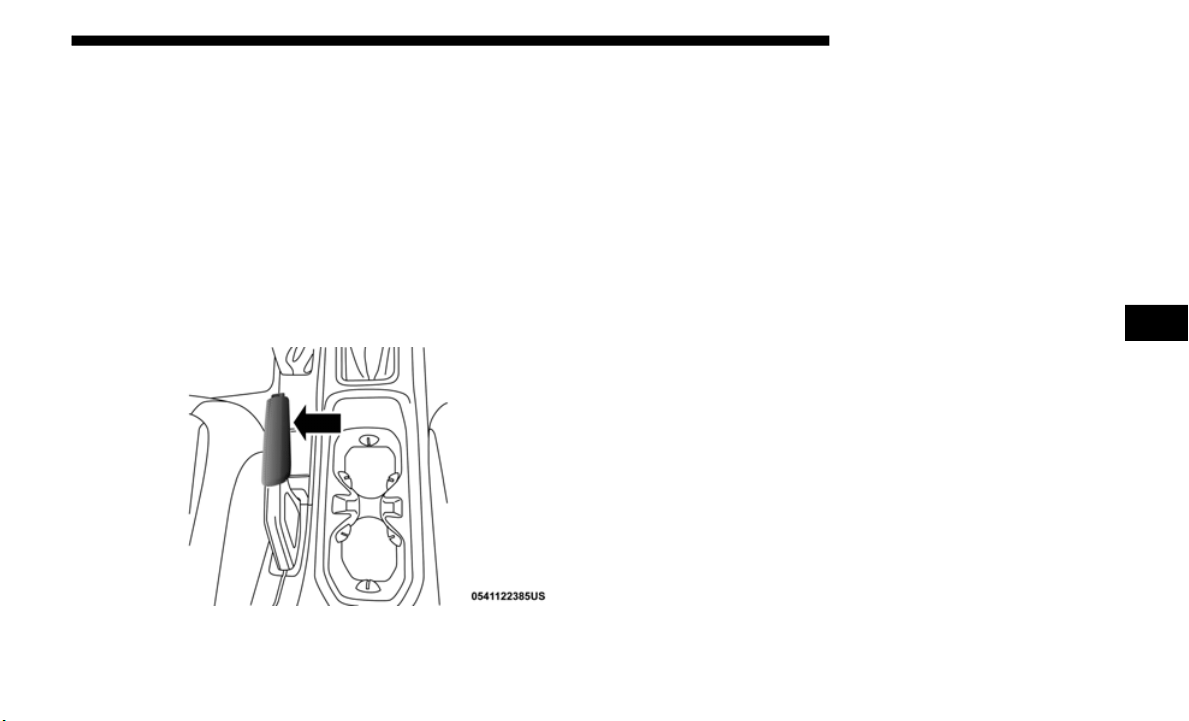
STARTING AND OPERATING 315
PARKING BRAKE
Before exiting the vehicle, make sure that the parking brake
is fully applied. Also, be certain to leave an automatic trans-
mission in PARK, or manual transmission in REVERSE or
FI
RST gear
.
The parking brake lever is located in the center console. To
a
p
ply the
parking brake, pull the lever up as firmly as
possible. To release the parking brake, pull the lever up
slightly, push the center button, then lower the lever
completely.
Parking Brake Lever
When the parking brake is applied with the ignition switch
ON, the
“Brake Warning Light” in the instrument cluster
will illuminate.
NOTE:
• When the parking brake is applied and the automatic
transmi
ssion is placed in gear, the “Brake Warning Light”
will flash. If vehicle speed is detected, a chime will sound
to alert the driver. Fully release the parking brake before
attempting to move the vehicle.
• This light only shows that the parking brake is applied. It
does no
t show the degree of brake application.
When parking on a hill, it is important to turn the front
wheels to
ward the curb on a downhill grade and away from
the curb on an uphill grade. For vehicles equipped with an
automatic transmission, apply the parking brake before
placing the gear selector in PARK, otherwise the load on the
transmission locking mechanism may make it difficult to
move the gear selector out of PARK. The parking brake
should always be applied whenever the driver is not in the
vehicle.
5

316 STARTING AND OPERATING
(Continued)
WARNING!
• Never use the PARK position on an automatic trans-
mission
as a substitute for the parking brake. Always
apply th
e parking brake fully when parked to guard
against vehicle movement and possible injury or
damage.
• When exiting the vehicle, always remove the key fob
from th
e ignition and lock your vehicle.
• Never leave children alone in a vehicle, or with access
to an u
nlocked vehicle. Allowing children to be in a
vehicle unattended is dangerous for a number of
reasons. A child or others could be seriously or fatally
injured. Children should be warned not to touch the
parking brake, brake pedal or the gear selector.
• Do not leave the key fob in or near the vehicle, or in a
location
accessible to children. A child could operate
power windows, other controls, or move the vehicle.
• Be sure the parking brake is fully disengaged before
driving; failure to do so can lead to brake failure and a
collision.
• Always fully apply the parking brake when leaving
your vehicle or it may roll and cause damage or injury.
Also, be certain to leave an automatic transmission in
PARK, a manual transmission in REVERSE or first
gear. Failure to do so may cause the vehicle to roll and
cause damage or injury.
CAUTION!
If the “Brake Warning Light” remains on with the
p
arking
brake released, a brake system malfunction is
indicated. Have the brake system serviced by an
authorized dealer immediately.
WARNING! (Continued)
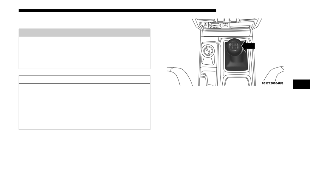
STARTING AND OPERATING 317
MANUAL TRANSMISSION — IF EQUIPPED
NOTE:
During cold weather, you may experience increased effort in
shifting
until the transmission fluid warms up. This is
normal.
Manual Transmission Shifter
To shift the gears, fully press the clutch pedal and place the
gear sele
ctor into the desired gear position (the diagram for
the engagement of the gears is displayed on the handle of the
selector).
WARNING!
You or others could be injured if you leave the vehicle
unattend
ed without having the parking brake fully
applied. The parking brake should always be applied
when the driver is not in the vehicle, especially on an
incline.
CAUTION!
• Never drive with your foot resting on the clutch pedal,
or attempt to hold the vehicle on a hill with the clutch
pedal partially engaged, as this will cause abnormal
wear on the clutch.
• Do not drive with your hand resting on the gear selector
as the
force exerted, even if slight, could lead over time
to premature wear of the gearbox internal components.
5
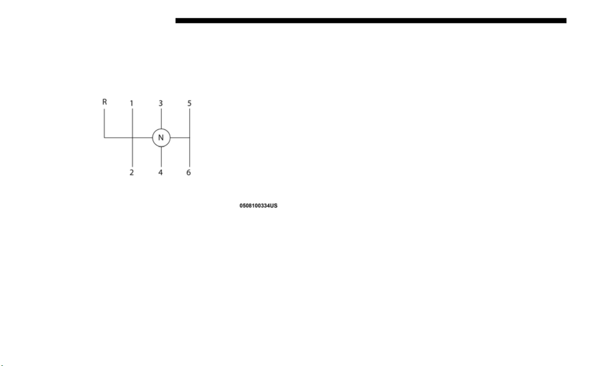
318 STARTING AND OPERATING
To engage REVERSE gear from the NEUTRAL position, lift
the REVERSE ring, located below the knob and move the
gear selector all the way left and then forward.
Shift Pattern
Shifting
Fully press the clutch pedal before shifting gears. As you
release the clutch pedal, lightly press the accelerator pedal.
You should always use first gear when starting from a
standing
position.
NOTE:
A certain amount of noise from the transmission is normal.
T
his noi
se can be most noticeable when the vehicle is idling
in NEUTRAL with the clutch engaged (clutch pedal
released), but it may also be heard when driving. The noise
may also be more noticeable when the transmission is warm.
This noise is normal and is not an indication of a problem
with your clutch or transmission.
STARTING AND OPERATING 319
(Continued)
Recommended Vehicle Shift Speeds
To utilize your manual transmission efficiently for both fuel economy and performance, it should be upshifted as listed in
recomme
nded shift speed chart. Shift at the vehicle speeds listed for acceleration. When heavily loaded or pulling a trailer
these recommended up-shift speeds may not apply.
NOTE:
Vehicle speeds shown in the chart above are for 2H and 4H
only, ve
hicle speeds in 4L would be significantly less.
Downshifting
Moving from a high gear down to a lower gear is recom-
mended to preserve brakes when driving down steep hills.
In addi
tion, downshifting at the right time provides better
acceleration when you desire to resume speed. Downshift
progressively. Do not skip gears to avoid overspeeding the
engine and clutch.
NOTE:
Above certain speeds downshifts may be blocked and not
availab
le.
Manual Transmission Shift Speeds in MPH (KM/H)
Engine Speeds 1 to 2 2 to 3 3 to 4 4 to 5 5 to 6
3.6L
Accel. 15 (24) 24 (39) 50 (80) 65 (104) 70 (112)
Cruise 10 (16) 19 (31) 40 (64) 55 (88) 65 (105)
WARNING!
Do not downshift for additional engine braking on a
slipper
y surface. The drive wheels could lose their grip,
and the vehicle could skid.
CAUTION!
• Skipping gears and downshifting into lower gears at
higher
vehicle speeds can damage the engine and
clutch systems, Any attempt to shift into lower gear
with clutch pedal depressed may result damage to the
clutch system. Shifting into lower gear and releasing
the clutch may result in engine damage.
5
320 STARTING AND OPERATING
(Continued)
Maximum Recommended Downshift Speeds
NOTE:
Vehicle speeds shown in the chart above are for 2H and 4H
only, ve
hicle speeds in 4L would be significantly less.
• When descending a hill, be very careful to downshift
one gear
at a time to prevent overspeeding the engine
which can cause engine damage, and/or clutch damage,
even if the clutch pedal is pressed. If transfer case is in
low range the vehicle speeds to cause engine and clutch
damage are significantly lower.
• Failure to follow the maximum recommended down-
shifti
ng speeds may cause the engine damage and/or
damage t
he clutch, even if the clutch pedal is pressed.
CAUTION! (Continued)
• Descending a hill in low range with clutch pedal
depressed could result in clutch damage.
CAUTION!
Failure to follow the maximum recommended
downshif
ting speeds may cause the engine to overspeed
and/or damage the clutch disc, even if the clutch pedal is
pressed.
CAUTION! (Continued)
Manual Transmission Downshift Speeds in MPH (KM/H)
Gear Selection 6 to 5 5 to 4 4 to 3 3 to 2 2 to 1
Maximum Speed 80 (129) 70 (113) 50 (81) 30 (48) 15 (24)

STARTING AND OPERATING 321
(Continued)
(Continued)
AUTOMATIC TRANSMISSION — IF EQUIPPED
NOTE:
You must press and hold the brake pedal while shifting out
of PARK
.
CAUTION!
• Shift into or out of PARK or REVERSE only after the
vehicle
has come to a complete stop.
• Do not shift between PARK, REVERSE, NEUTRAL, or
DRIVE
when the engine is above idle speed.
• Before shifting into any gear, make sure your foot is
firmly
pressing the brake pedal.
WARNING!
• Never use the PARK position as a substitute for the
parkin
g brake. Always apply the parking brake fully
when exiting the vehicle to guard against vehicle move
-
ment and possible injury or damage.
• Y
our vehicle could move and injure you and others if it
is not
in PARK. Check by trying to move the transmis-
sion gear selector out of PARK with the brake pedal
r
elease
d. Make sure the transmission is in PARK before
exiting the vehicle.
• The transmission may not engage PARK if the vehicle
is moving. Always bring the vehicle to a complete stop
before shifting to PARK, and verify that the transmis
-
sion gear position indicator solidly indicates PARK (P)
without
blinking. Ensure that the vehicle is completely
stopped, and the PARK position is properly indicated,
before exiting the vehicle.
• It is dangerous to shift out of PARK or NEUTRAL if the
engine
speed is higher than idle speed. If your foot is
not firmly pressing the brake pedal, the vehicle could
accelerate quickly forward or in reverse. You could lose
control of the vehicle and hit someone or something.
Only shift into gear when the engine is idling normally
and your foot is firmly pressing the brake pedal.
• Unintended movement of a vehicle could injure those
in or n
ear the vehicle. As with all vehicles, you should
never exit a vehicle while the engine is running. Before
exiting a vehicle, always come to a complete stop, then
apply the parking brake, shift the transmission into
PARK, and turn the ignition OFF. When the ignition is
in the OFF mode, the transmission is locked in PARK,
securing the vehicle against unwanted movement.
WARNING! (Continued)
5

322 STARTING AND OPERATING
Ignition Park Interlock
This vehicle is equipped with an Ignition Park Interlock
which requires the transmission to be in PARK before the
ignition can be turned to the OFF mode. This helps the driver
avoid inadvertently leaving the vehicle without placing the
transmission in PARK. This system also locks the transmis
-
sion in PARK whenever the ignition is in the OFF mode.
NOTE:
The transmission is NOT locked in PARK when the ignition
i
s in t
he ACC mode (even though the engine will be off).
Ensure that the transmission is in PARK, and the ignition is
OFF (not in ACC mode) before exiting the vehicle.
Brake/Transmission Shift Interlock System
This vehicle is equipped with a Brake Transmission Shift
Interlock system (BTSI) that holds the transmission gear
selector in PARK unless the brakes are applied. To shift the
transmission out of PARK, the engine must be running and
the brake pedal must be pressed. The brake pedal must also
be pressed to shift from NEUTRAL into DRIVE or REVERSE
when the vehicle is stopped or moving at low speeds.
Eight–Speed Automatic Transmission
The transmission gear range (PRNDM) is displayed both
beside the gear selector and in the instrument cluster. To
select a gear range, press the lock button on the gear selector
and move the selector rearward or forward. To shift the
transmission out of PARK, the engine must be running and
the brake pedal must be pressed. You must also press the
brake pedal to shift from NEUTRAL into DRIVE or
REVERSE when the vehicle is stopped or moving at low
speeds. Select the DRIVE range for normal driving.
• When exiting the vehicle, always make sure the igni-
tion is
in the OFF mode, remove the key fob from the
vehicle,
and lock the vehicle.
• Never leave children alone in a vehicle, or with access
to an u
nlocked vehicle. Allowing children to be in a
vehicle unattended is dangerous for a number of
reasons. A child or others could be seriously or fatally
injured. Children should be warned not to touch the
parking brake, brake pedal or the transmission gear
selector.
• Do not leave the key fob in or near the vehicle (or in a
location
accessible to children), and do not leave the
ignition in the ACC or ON/RUN mode. A child could
operate power windows, other controls, or move the
vehicle.
WARNING! (Continued)
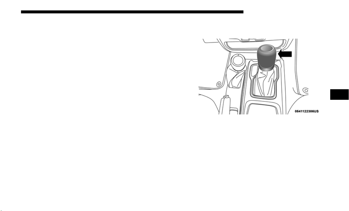
STARTING AND OPERATING 323
NOTE:
In the event of a mismatch between the gear selector position
and the
actual transmission gear (for example, driver selects
PARK while driving), the position indicator will blink
continuously until the selector is returned to the proper posi
-
tion, or the requested shift can be completed.
The electronically-controlled transmission adapts its shift
s
chedule
based on driver inputs, along with environmental
and road conditions. The transmission electronics are
self-calibrating; therefore, the first few shifts on a new
vehicle may be somewhat abrupt. This is a normal condition,
and precision shifts will develop within a few hundred miles
(kilometers).
Only shift from DRIVE to PARK or REVERSE when the
accelera
tor pedal is released and the vehicle is stopped. Be
sure to keep your foot on the brake pedal when shifting
between these gears.
The transmission gear selector provides PARK, REVERSE,
NEUTRAL,
DRIVE and MANUAL (AutoStick) shift posi-
tions. Manual shifts can be made using the AutoStick shift
c
ontrol.
Toggling the gear selector forward (-) or rearward
(+) while in the MANUAL (AutoStick) position (beside the
DRIVE position) will manually select the transmission gear,
and will display the current gear in the instrument cluster.
Refer to "AutoStick" in this section for further information.
Gear Selector
NOTE:
If the gear selector cannot be moved to the PARK, REVERSE,
or NEUTR
AL position (when pushed forward), it is prob-
ably in the AutoStick (+/-) position (beside the DRIVE posi-
tion). In AutoStick mode, the transmission gear (1, 2, 3, etc.)
i
s displ
ayed in the instrument cluster. Move the gear selector
to the right (into the DRIVE [D] position) for access to PARK,
REVERSE, and NEUTRAL.
5

324 STARTING AND OPERATING
(Continued)
Gear Ranges
Do not depress the accelerator pedal when shifting from
PARK or
NEUTRAL into another gear range.
NOTE:
After selecting any gear range, wait a moment to allow the
s
electe
d gear to engage before accelerating. This is especially
important when the engine is cold.
PARK (P)
This range supplements the parking brake by locking the
transmi
ssion. The engine can be started in this range. Never
attempt to use PARK while the vehicle is in motion. Apply
the parking brake when exiting the vehicle in this range.
When parking on a level surface, you may shift the transmis-
sion into PARK first, and then apply the parking brake.
When parking on a hill, apply the parking brake before
s
hiftin
g the transmission to PARK. As an added precaution,
turn the front wheels toward the curb on a downhill grade
and away from the curb on an uphill grade.
When exiting the vehicle, always:
• A
pply the parking brake,
• Shift
the transmission into PARK,
• Turn t
he ignition OFF and,
• Remove
the key fob from the vehicle.
NOTE:
On
four-wheel drive vehicles be sure that the transfer case is
i
n
a dr
ive position.
WARNING!
• Never use the PARK position as a substitute for the
parkin
g brake. Always apply the parking brake fully
when exiting the vehicle to guard against vehicle move
-
ment and possible injury or damage.
• Y
our vehicle could move and injure you and others if it
is not
in PARK. Check by trying to move the transmis-
sion gear selector out of PARK with the brake pedal
r
elease
d. Make sure the transmission is in PARK before
exiting the vehicle.
STARTING AND OPERATING 325
(Continued)
(Continued)
• The transmission may not engage PARK if the vehicle
is moving. Always bring the vehicle to a complete stop
before shifting to PARK, and verify that the transmis
-
sion gear position indicator solidly indicates PARK (P)
without
blinking. Ensure that the vehicle is completely
stopped, and the PARK position is properly indicated,
before exiting the vehicle.
• It is dangerous to shift out of PARK or NEUTRAL if the
engine
speed is higher than idle speed. If your foot is
not firmly pressing the brake pedal, the vehicle could
accelerate quickly forward or in reverse. You could lose
control of the vehicle and hit someone or something.
Only shift into gear when the engine is idling normally
and your foot is firmly pressing the brake pedal.
• Unintended movement of a vehicle could injure those
in or n
ear the vehicle. As with all vehicles, you should
never exit a vehicle while the engine is running. Before
exiting a vehicle, always come to a complete stop, then
apply the parking brake, shift the transmission into
PARK, and turn the ignition OFF. When the ignition is
in the OFF mode, the transmission is locked in PARK,
securing the vehicle against unwanted movement.
WARNING! (Continued)
• When exiting the vehicle, always make sure the igni-
tion is in the OFF mode, remove the key fob from the
vehicle,
and lock the vehicle.
• Never leave children alone in a vehicle, or with access
to an u
nlocked vehicle. Allowing children to be in a
vehicle unattended is dangerous for a number of
reasons. A child or others could be seriously or fatally
injured. Children should be warned not to touch the
parking brake, brake pedal or the transmission gear
selector.
• Do not leave the key fob in or near the vehicle (or in a
location
accessible to children), and do not leave the
ignition in the ACC or ON/RUN mode. A child could
operate power windows, other controls, or move the
vehicle.
CAUTION!
• Before moving the transmission gear selector out of
PARK,
you must start the engine, and also press the
brake pedal. Otherwise, damage to the gear selector
could result.
WARNING! (Continued)
5

326 STARTING AND OPERATING
The following indicators should be used to ensure that you
have properly engaged the transmission into the PARK posi-
tion:
• W
hen shifting into PARK, push the lock button on the gear
select
or and firmly move the selector all the way forward
until it stops and is fully seated.
• Look at the transmission gear position display and verify
that i
t indicates the PARK position (P), and is not blinking.
• With brake pedal released, verify that the gear selector will
not mo
ve out of PARK.
NOTE:
If the gear selector cannot be moved to the PARK position
(
when pu
shed forward), it is probably in the AutoStick (+/-)
position (beside the DRIVE position). In AutoStick mode, the
transmission gear (1, 2, 3, etc.) is displayed in the instrument
cluster. Move the gear selector to the right (into the DRIVE
[D] position) for access to PARK, REVERSE, and NEUTRAL.
REVERSE (R)
This range is for moving the vehicle backward. Shift into
REVERSE only after the vehicle has come to a complete stop.
NEUTRAL (N)
Use this range when the vehicle is standing for prolonged
p
eriods
with the engine running. Apply the parking brake and
shift the transmission into PARK if you must exit the vehicle.
• DO NOT race the engine when shifting from PARK or
NEUTRA
L into another gear range, as this can damage
the drivetrain.
CAUTION! (Continued)
WARNING!
Do not coast in NEUTRAL and never turn off the
ignition
to coast down a hill. These are unsafe practices
that limit your response to changing traffic or road
conditions. You might lose control of the vehicle and
have a collision.
CAUTION!
Towing the vehicle, coasting, or driving for any other
reason w
ith the transmission in NEUTRAL can cause
severe transmission damage.
Refer to “Recreational Towing” in “Starting And
Operati
ng” and “Towing A Disabled Vehicle” in “In
Case Of Emergency” for further information.

STARTING AND OPERATING 327
DRIVE (D)
This range should be used for most city and highway
driving.
It provides the smoothest upshifts and downshifts,
and the best fuel economy. The transmission automatically
upshifts through all forward gears. The DRIVE position
provides optimum driving characteristics under all normal
operating conditions.
When frequent transmission shifting occurs (such as when
operati
ng the vehicle under heavy loading conditions, in
hilly terrain, traveling into strong head winds, or while
towing a heavy trailer), use the AutoStick shift control (refer
to "AutoStick" in this section for further information) to
select a lower gear. Under these conditions, using a lower
gear will improve performance and extend transmission life
by reducing excessive shifting and heat buildup.
During extremely cold temperatures (-22°F [-30°C] or
below),
transmission operation may be modified depending
on engine and transmission temperature as well as vehicle
speed. Normal operation will resume once the transmission
temperature has risen to a suitable level.
MANUAL (M)
The MANUAL (M, +/-) position (beside the DRIVE position)
enables
full manual control of transmission shifting (also
known as AutoStick mode; refer to “AutoStick” in this
section for further information). Toggling the gear selector
forward (-) or rearward (+) while in the MANUAL (AutoS
-
tick) position will manually select the transmission gear, and
will dis
play the current gear in the instrument cluster.
Transmission Limp Home Mode
Transmission function is monitored electronically for
a
bnorma
l conditions. If a condition is detected that could
result in transmission damage, Transmission Limp Home
Mode is activated. In this mode, the transmission may
operate only in certain gears, or may not shift at all. Vehicle
performance may be severely degraded and the engine may
stall. In some situations, the transmission may not re-engage
if the engine is turned off and restarted. The Malfunction
Indicator Light (MIL) may be illuminated. A message in the
instrument cluster will inform the driver of the more serious
conditions, and indicate what actions may be necessary.
5

328 STARTING AND OPERATING
In the event of a momentary problem, the transmission can
be reset to regain all forward gears by performing the
following steps:
NOTE:
In cases where the instrument cluster message indicates the
transmi
ssion may not re-engage after engine shutdown,
perform this procedure only in a desired location (prefer
-
ably, at an authorized dealer).
1. Stop the vehicle.
2. Shif
t the transmission into PARK, if possible. If not, shift
the tr
ansmission to NEUTRAL.
3. Push and hold the ignition switch until the engine turns
OFF.
4. Wai
t approximately 30 seconds.
5. Rest
art the engine.
6. Shif
t into the desired gear range. If the problem is no
longer
detected, the transmission will return to normal
operation.
NOTE:
Even if the transmission can be reset, we recommend that
you visi
t an authorized dealer at your earliest possible
convenience. An authorized dealer has diagnostic equip
-
ment to assess the condition of your transmission.
If the transmission cannot be reset, authorized dealer service
is requ
ired.
AutoStick
AutoStick is a driver-interactive transmission feature
providi
ng manual shift control, giving you more control of
the vehicle. AutoStick allows you to maximize engine
braking, eliminate undesirable upshifts and downshifts, and
improve overall vehicle performance. This system can also
provide you with more control during passing, city driving,
cold slippery conditions, mountain driving, trailer towing,
and many other situations.

STARTING AND OPERATING 329
Operation
To activate AutoStick mode, move the gear selector into the
MANUAL
(M) position (beside the DRIVE position). The
current transmission gear will be displayed in the instru
-
ment cluster. In AutoStick mode, you can use the gear
selecto
r (in the MANUAL position) to manually shift the
transmission. Tapping the gear selector forward (-) while in
the MANUAL (M) position will downshift the transmission
to the next lower gear. Tapping the selector rearward (+) will
command an upshift.
In AutoStick mode, the transmission will shift up or down
when (+/-)
is manually selected by the driver, unless an
engine lugging or overspeed condition would result. It will
remain in the selected gear until another upshift or down
-
shift is chosen, except as described below.
• T
he transmission will automatically downshift as the
vehicl
e slows (to prevent engine lugging) and will display
the current gear.
• The transmission will automatically downshift to first gear
when co
ming to a stop. After a stop, the driver should
manually upshift (+) the transmission as the vehicle is
accelerated.
• You can start out, from a stop, in first or second gear (or
third
gear, in 4LO range). Tapping (+) (at a stop) will allow
starting in second gear. Starting out in second or third gear
can be helpful in snowy or icy conditions.
• If a requested downshift would cause the engine to
over-s
peed, that shift will not occur.
• The system will ignore attempts to upshift at too low of a
vehicl
e speed.
• Holding the gear selector in the (-) position will downshift
the tr
ansmission to the lowest gear possible at the current
speed.
• Transmission shifting will be more noticeable when Auto-
Stick i
s enabled.
• T
he system may revert to automatic shift mode if a fault or
overhe
at condition is detected.
NOTE:
When Hill Descent Control is enabled, AutoStick is not
a
ctive.
5
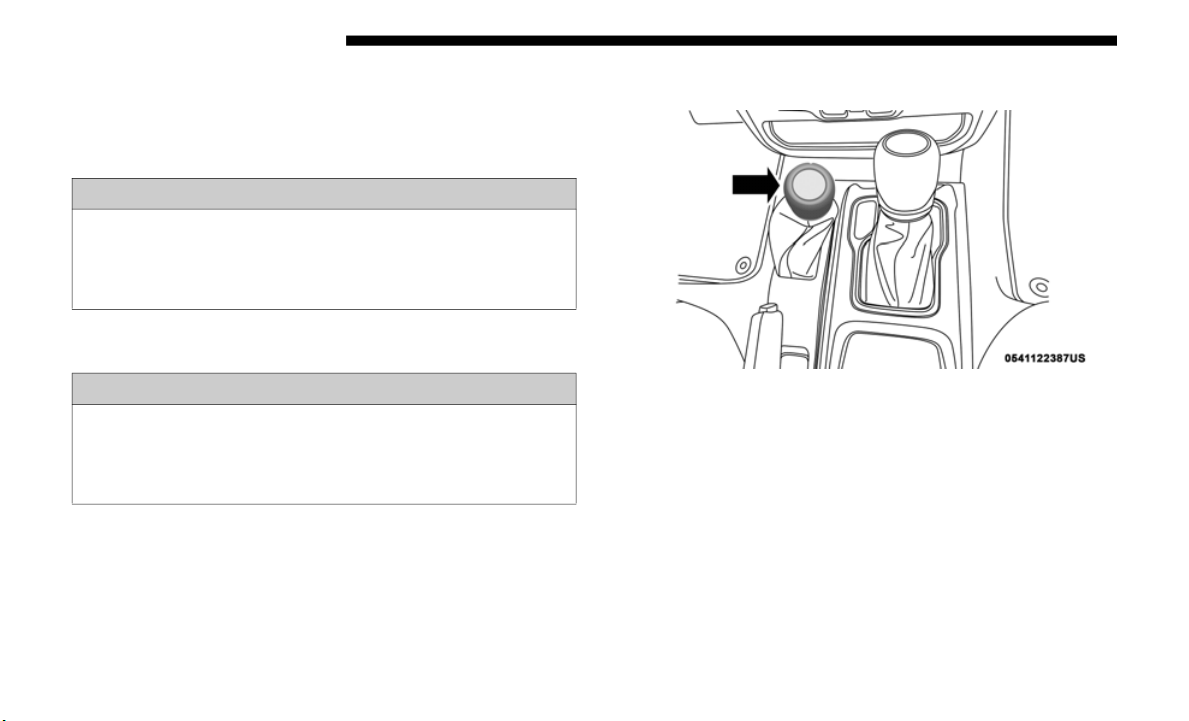
330 STARTING AND OPERATING
To disengage AutoStick mode, return the gear selector to the
DRIVE position. You can shift in or out of the AutoStick posi-
tion at any time without taking your foot off the accelerator
p
edal.
FOUR–WHEEL DRIVE OPERATION
Four-Position Transfer Case
Four-Wheel Drive Gear Selector
The transfer case provides four mode positions:
• 2H (Two-Wheel Drive High Range)
• 4H (Four
-Wheel Drive High Range)
• N (Neut
ral)
• 4L (Four
-Wheel Drive Low Range)
WARNING!
Do not downshift for additional engine braking on a
slippery
surface. The drive wheels could lose their grip
and the vehicle could skid, causing a collision or
personal injury.
WARNING!
Failure to engage a transfer case position completely can
cause tr
ansfer case damage or loss of power and vehicle
control. You could have a collision. Do not drive the
vehicle unless the transfer case is fully engaged.

STARTING AND OPERATING 331
For additional information on the appropriate use of each
transfer case mode position, see the information below:
2H
Rear Wheel Drive High Range — This range is for normal
s
treet
and highway driving on dry, hard surfaced roads.
4H
Four-Wheel Drive High Range — This range maximizes
torque
to the front driveshaft, forcing the front and rear
wheels to rotate at the same speed. This range provides addi
-
tional traction for loose, slippery road surfaces only.
NEUTRAL (N)
Neutral — This range disengages both the front and rear
driveshafts from the powertrain. To be used for flat towing
behind another vehicle.
Refer to “Recreational Towing” in “Starting And Operating”
for fur
ther information.
4L
Four-Wheel Drive Low Range — This range provides low
s
peed f
our-wheel drive. It maximizes torque to the front
driveshaft, forcing the front and rear wheels to rotate at the
same speed. This range provides additional traction and
maximum pulling power for loose, slippery road surfaces
only. Do not exceed 25
mph (40 km/h).
The transfer case is intended to be driven in the 2H position
for nor
mal street and highway conditions, such as
hard-surfaced roads.
In the event that additional traction is required, the transfer
case 4H
and 4L positions can be used to lock the front and
rear driveshafts together, forcing the front and rear wheels to
rotate at the same speed. The 4H and 4L positions are
intended for loose, slippery road surfaces only and not
intended for normal driving. Driving in the 4H and 4L posi
-
tions on hard-surfaced roads will cause increased tire wear
WARNING!
You or others could be injured or killed if you leave the
vehicle
unattended with the transfer case in the
NEUTRAL (N) position without first fully engaging the
parking brake. The transfer case NEUTRAL (N) position
disengages both the front and rear driveshafts from the
powertrain, and will allow the vehicle to roll, even if the
automatic transmission is in PARK (or manual
transmission is in gear). The parking brake should
always be applied when the driver is not in the vehicle.
5

332 STARTING AND OPERATING
and damage to the driveline components. Refer to “Shifting
Procedures” in this section for further information on
shifting into 4H or 4L.
The instrument cluster alerts the driver that the vehicle is in
four-whe
el drive, and the front and rear driveshafts are
locked together. The light will illuminate when the transfer
case is shifted into the 4H position.
When operating your vehicle in 4L, the engine speed will be
approxi
mately three times (four times for Rubicon models)
that of the 2H or 4H positions at a given road speed. Take
care not to overspeed the engine.
Proper operation of four-wheel drive vehicles depends on
tires o
f equal size, type, and circumference on each wheel.
Any difference will adversely affect shifting and cause
damage to the transfer case.
Because four-wheel drive provides improved traction, there
is a te
ndency to exceed safe turning and stopping speeds. Do
not go faster than road conditions permit.
Shifting Procedures
2H To 4H Or 4H To 2H
Shifting between 2H and 4H can be made with the vehicle
stopped
or in motion. The preferred shifting speed would be
0 to 45
mph (72 km/h). With the vehicle in motion, the
transfe
r case will engage/disengage faster if you momen-
tarily release the accelerator pedal after completing the shift.
D
o not
accelerate while shifting the transfer case. Apply a
constant force when shifting the transfer case lever.
NOTE:
• Do not attempt to make a shift while only the front or rear
wheels
are spinning. The front and rear driveshaft speeds
must be equal for the shift to take place. Shifting while
only the front or rear wheels are spinning can cause
damage to the transfer case.
• Delayed shifts out of four-wheel drive may be experienced
due to
uneven tire wear, low or uneven tire pressures,
excessive vehicle loading, or cold temperatures.
• Shifting effort will increase with speed, this is normal.
During
cold weather, you may experience increased effort in
shiftin
g until the transfer case fluid warms up. This is
normal.
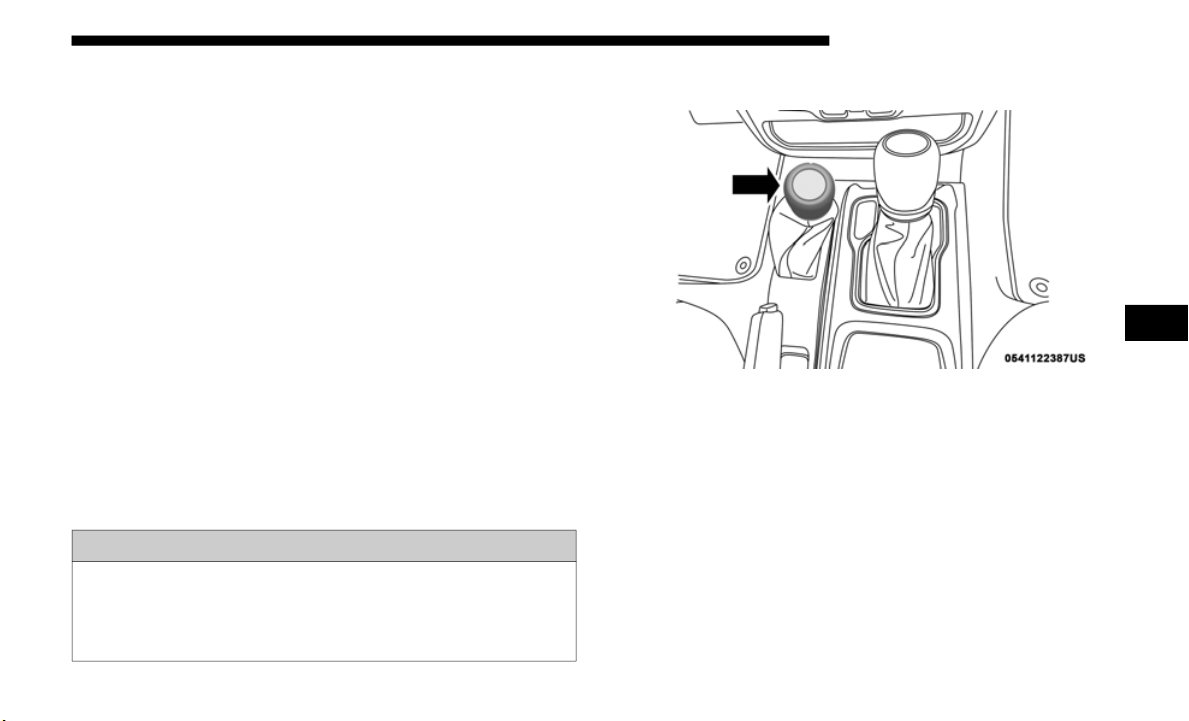
STARTING AND OPERATING 333
4H To 4L Or 4L To 4H
With the vehicle rolling at 2 to 3 mph (3 to 5 km/h), shift an
automati
c transmission into NEUTRAL (N), or press the
clutch pedal on a manual transmission. While the vehicle is
coasting at 2 to 3
mph (3 to 5 km/h), shift the transfer case
lever fi
rmly to the desired position. Do not pause with the
transfer case in N (Neutral). Once the shift is completed,
place the automatic transmission into DRIVE or release the
clutch pedal on a manual transmission.
NOTE:
Shifting into or out of 4L is possible with the vehicle
complete
ly stopped; however, difficulty may occur due to
the mating teeth not being properly aligned. Several
attempts may be required for clutch teeth alignment and
shift completion to occur. The preferred method is with the
vehicle rolling at 2 to 3
mph (3 to 5 km/h). Avoid attempting
to engage
or disengage 4L with the vehicle moving faster
than 2 to 3
mph (3 to 5 km/h).
Five-Position Transfer Case
Four-Wheel Drive Gear Selector
The transfer case provides five mode positions:
• 2H (Two-Wheel Drive High Range)
• 4H Auto
(Four-Wheel Drive Auto High Range)
• 4H PT (
Four-Wheel Drive Part Time High Range)
• N (Neut
ral)
• 4L (Four
-Wheel Drive Low Range)
WARNING!
Failure to engage a transfer case position completely can
cause tr
ansfer case damage or loss of power and vehicle
control. You could have a collision. Do not drive the
vehicle unless the transfer case is fully engaged.
5

334 STARTING AND OPERATING
For additional information on the appropriate use of each
transfer case mode position, see the information below:
2H
Rear Wheel Drive High Range — This range is for normal
s
treet
and highway driving on dry, hard surfaced roads.
4H AUTO
Four-Wheel Drive Auto High Range — This range sends
power to
the front wheels. The four-wheel drive system will
be automatically engaged when the vehicle senses a loss of
traction. Additional traction for varying road conditions.
4H P-T
Four-Wheel Drive Part Time High Range — This range maxi-
mizes torque to the front driveshaft, forcing the front and
r
ear whe
els to rotate at the same speed. This range provides
additional traction for loose, slippery road surfaces only.
NEUTRAL (N)
Neutral — This range disengages both the front and rear
drivesh
afts from the powertrain. To be used for flat towing
behind another vehicle.
Refer to “Recreational Towing” in “Starting And Operating”
for fur
ther information.
WARNING!
You or others could be injured or killed if you leave the
vehicle
unattended with the transfer case in the
NEUTRAL (N) position without first fully engaging the
parking brake. The transfer case NEUTRAL (N) position
disengages both the front and rear driveshafts from the
powertrain, and will allow the vehicle to roll, even if the
automatic transmission is in PARK (or manual
transmission is in gear). The parking brake should
always be applied when the driver is not in the vehicle.

STARTING AND OPERATING 335
4L
Four-Wheel Drive Low Range — This range provides low
speed f
our-wheel drive. It maximizes torque to the front
driveshaft, forcing the front and rear wheels to rotate at the
same speed. This range provides additional traction and
maximum pulling power for loose, slippery road surfaces
only. Do not exceed 25
mph (40 km/h).
This transfer case is designed to be driven in the two-wheel
drive p
osition (2WD) or four-wheel drive position (4WD
AUTO) for normal street and highway conditions on dry
hard surfaced roads. Driving the vehicle in 2WD will have
greater fuel economy benefits as the front axle is not engaged
in 2WD.
For variable driving conditions, the 4WD AUTO mode can
be used
. In this mode, the front axle is engaged, but the
vehicle's power is sent to the rear wheels. Four-wheel drive
will be automatically engaged when the vehicle senses a loss
of traction. Because the front axle is engaged, this mode will
result in lower fuel economy than the 2WD mode.
In the event that additional traction is required, the transfer
case 4H
and 4L positions can be used to lock the front and
rear driveshafts together, forcing the front and rear wheels to
rotate at the same speed. The 4H and 4L positions are
intended for loose, slippery road surfaces only and not
intended for normal driving. Driving in the 4H and 4L posi
-
tions on hard-surfaced roads will cause increased tire wear
a
nd dam
age to the driveline components. Refer to “Shifting
Procedures” in this section for further information on
shifting into 4H or 4L.
The instrument cluster alerts the driver that the vehicle is in
four-whe
el drive, and the front and rear driveshafts are
locked together. The light will illuminate when the transfer
case is shifted into the 4H position.
When operating your vehicle in 4L, the engine speed will be
approxi
mately three times (four times for Rubicon models)
that of the 2H or 4H positions at a given road speed. Take
care not to overspeed the engine.
Proper operation of four-wheel drive vehicles depends on
tires o
f equal size, type, and circumference on each wheel.
Any difference will adversely affect shifting and cause
damage to the transfer case.
Because four-wheel drive provides improved traction, there
is a te
ndency to exceed safe turning and stopping speeds. Do
not go faster than road conditions permit.
5

336 STARTING AND OPERATING
Shifting Procedures
2H To 4H Auto Or 4H Auto To 2H
Shifting between 2H and 4H Auto can be made with the
vehicle
stopped or in motion. The preferred shifting speed
would be 0 to 45
mph (72 km/h). With the vehicle in motion,
the tra
nsfer case will engage/disengage faster if you
momentarily release the accelerator pedal after completing
the shift. Do not accelerate while shifting the transfer case.
Apply a constant force when shifting the transfer case lever.
2H/4H Auto To 4H Part Time Or 4H Part Time To 2H/4H
Auto
Shif
ting between 2H/4H AUTO to 4H PART TIME can be
made wit
h the vehicle stopped or in motion. The preferred
shifting speed would be 0 to 45
mph (72 km/h). With the
vehicle
in motion, the transfer case will engage/disengage
faster if you momentarily release the accelerator pedal after
completing the shift. Do not accelerate while shifting the
transfer case. Apply a constant force when shifting the
transfer case lever.
NOTE:
• D
o not attempt to make a shift while only the front or rear
wheels
are spinning. The front and rear driveshaft speeds
must be equal for the shift to take place. Shifting while
only the front or rear wheels are spinning can cause
damage to the transfer case.
• Delayed shifts out of four-wheel drive may be experienced
due to
uneven tire wear, low or uneven tire pressures,
excessive vehicle loading, or cold temperatures.
• Shifting effort will increase with speed, this is normal.
During
cold weather, you may experience increased effort in
shiftin
g until the transfer case fluid warms up. This is normal.

STARTING AND OPERATING 337
4H Part Time/4H Auto To 4L Or 4L To 4H Part Time/4H Auto
With the vehicle rolling at 2 to 3 mph (3 to 5 km/h), shift an
automat
ic transmission into NEUTRAL (N), or press the
clutch pedal on a manual transmission. While the vehicle is
coasting at 2 to 3
mph (3 to 5 km/h), shift the transfer case
lever f
irmly to the desired position. Do not pause with the
transfer case in N (Neutral). Once the shift is completed,
place the automatic transmission into DRIVE or release the
clutch pedal on a manual transmission.
NOTE:
Shifting into or out of 4L is possible with the vehicle
complet
ely stopped; however, difficulty may occur due to
the mating teeth not being properly aligned. Several
attempts may be required for clutch teeth alignment and
shift completion to occur. The preferred method is with the
vehicle rolling at 2 to 3
mph (3 to 5 km/h). Avoid attempting
to engage
or disengage 4L with the vehicle moving faster
than 2 to 3
mph (3 to 5 km/h).
Trac-Lok Rear Axle — If Equipped
The Trac-Lok rear axle provides a constant driving force to
both rear wheels and reduces wheel spin caused by the loss
of traction at one driving wheel. If traction differs between
the two rear wheels, the differential automatically propor
-
tions the usable torque by providing more torque to the
wh
eel th
at has traction.
Trac-Lok is especially helpful during slippery driving condi-
tions. With both rear wheels on a slippery surface, a slight
a
pplica
tion of the accelerator will supply maximum traction.
WARNING!
Failure to engage a transfer case position completely can
cause t
ransfer case damage or loss of power and vehicle
control. You could have a collision. Do not drive the
vehicle unless the transfer case is fully engaged.
WARNING!
On vehicles equipped with a limited-slip differential,
never ru
n the engine with one rear wheel off the ground.
The vehicle may drive through the rear wheel remaining
on the ground and cause you to lose control of your
vehicle.
5
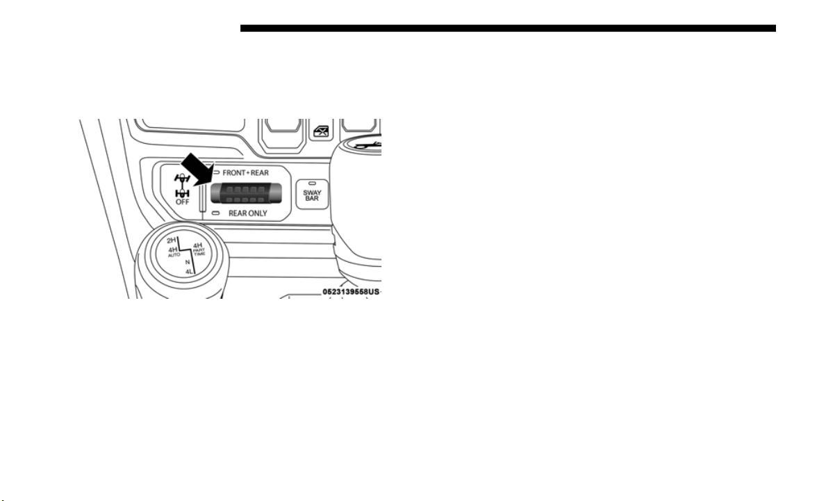
338 STARTING AND OPERATING
Axle Lock (Tru-Lok) — Rubicon Models
The AXLE LOCK switch is located on the instrument panel
(to the right of the steering column).
Axle Lock Switch Panel
This feature will only activate when the following conditions
are met:
•
Ignition in RUN position, vehicle in 4L (Low) range.
• Vehicle
speed should be 10 mph (1
6 km/h) or less.
• Both right and left wheels on axle are at the same speed.
To acti
vate the system, push the AXLE LOCK switch down
to lock t
he rear axle only (the “REAR ONLY” will illumi-
nate), push the switch up to lock the front axle and rear axle
(
the “FRO
NT + REAR” will illuminate). When the rear axle
is locked, pushing the bottom of switch again will lock or
unlock the front axle.
NOTE:
The indicator lights will flash until the axles are fully locked
o
r unloc
ked.
To unlock the axles, push the AXLE LOCK OFF button.
Axle lock will disengage if the vehicle is taken out of 4L
(Low) ran
ge, or the ignition switch is turned to the OFF posi-
tion.
The axle lock disengages at speeds above 30 mph (48 km/h),
a
nd will
automatically re-lock once vehicle speed is less than
10
mph (16 km/h).
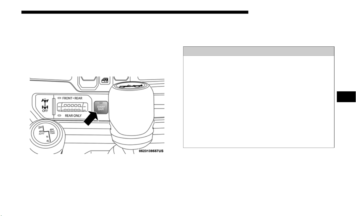
STARTING AND OPERATING 339
Electronic Sway Bar Disconnect — If Equipped
Your vehicle may be equipped with an electronic discon-
necting stabilizer/sway bar. This system allows greater front
suspensi
on travel in off-road situations.
This system is controlled by the SWAY BAR switch located
on the i
nstrument panel (to the right of the steering column).
Sway Bar Switch
Push the SWAY BAR switch to activate the system. Push the
switch aga
in to deactivate the system. The “Sway Bar Indi-
cator Light” (located in the instrument cluster) will illumi-
nate when the bar is disconnected. The “Sway Bar Indicator
L
ight” wil
l flash during activation transition, or when activa-
tion conditions are not met. The stabilizer/sway bar should
remain i
n on-road mode during normal driving conditions.
To disconnect the stabilizer/sway bar, shift to either 4H or
4L and p
ush the SWAY BAR switch to obtain the off-road
position. Refer to “Four-Wheel Drive Operation” in this
section for further information. The “Sway Bar Indicator
Light” will flash until the stabilizer/sway bar has been fully
disconnected.
WARNING!
Ensure the stabilizer/sway bar is reconnected before
driving on
hard surfaced roads or at speeds above
18
mph (29 km/h); a disconnected stabilizer/sway bar
may contri
bute to the loss of vehicle control, which could
result in serious injury. Under certain circumstances, the
front stabilizer/sway bar enhances vehicle stability and
assists with vehicle control. The system monitors vehicle
speed and will attempt to reconnect the stabilizer/sway
bar at speeds over 18
mph (29 km/h). This is indicated by
a flashi
ng or solid “Sway Bar Indicator Light.” Once
vehicle speed is reduced below 14
mph (22 km/h), the
system wi
ll once again attempt to return to off-road
mode.
5

340 STARTING AND OPERATING
NOTE:
The stabilizer/sway bar may be torque locked due to left and
right sus
pension height differences. This condition is due to
driving surface differences or vehicle loading. In order for
the stabilizer/sway bar to disconnect/reconnect, the right
and left halves of the bar must be aligned. This alignment
may require that the vehicle be driven onto level ground or
rocked from side to side.
To return to on-road mode, push the SWAY BAR switch
again.
ELECTRO-HYDRAULIC POWER STEERING
Your vehicle is equipped with an electro-hydraulic power
steering system that will give you good vehicle response and
increased ease of maneuverability in tight spaces. The
system will vary its assist to provide light efforts while
parking and good feel while driving. If the electro-hydraulic
power steering system experiences a fault that prevents it
from providing power steering assist, then the system will
provide mechanical steering capability.
If the “SERVICE POWER STEERING” message and
a flashing icon are displayed on the instrument
cluster
screen, it indicates that the vehicle needs to
be taken to the dealer for service. It is likely the vehicle has
lost power steering assistance. Refer to “Instrument Cluster
Display” in “Getting To Know Your Instrument Panel” for
further information.
WARNING!
If the stabilizer/sway bar will not return to on-road mode,
the “Sway
Bar Indicator Light” will flash in the instrument
cluster and vehicle stability may be reduced. Do not
attempt to drive the vehicle over 18
mph (29 km/h).
Driving f
aster than 18 mph (29 km/h) with a disconnected
stabiliz
er/sway bar may contribute to the loss of vehicle
control, which could result in serious injury.
CAUTION!
Extreme steering maneuvers may cause the electrically
driven pu
mp to reduce or stop power steering assistance
in order to prevent damage to the system. Normal
operation will resume once the system is allowed to cool.

STARTING AND OPERATING 341
If the “POWER STEERING HOT” message and an icon are
displayed on the instrument cluster screen, it indicates that
extreme steering maneuvers may have occurred, which
caused an over temperature condition in the power steering
system. You will lose power steering assistance momentarily
until the over temperature condition no longer exists. Once
driving conditions are safe, then pull over and let vehicle idle
for a few moments until the light turns off. Refer to “Instru
-
ment Cluster Display” in “Getting To Know Your Instru-
ment Panel” for further information.
NOTE:
• E
ven if power steering assistance is no longer operational,
it is
still possible to steer the vehicle. Under these condi-
tions there will be a substantial increase in steering effort,
e
specia
lly at very low vehicle speeds and during parking
maneuvers.
• If the condition persists, see your authorized dealer for
servic
e.
STOP/START SYSTEM — AUTOMATIC
TRANSMISSION (IF EQUIPPED)
The Stop/Start function is developed to reduce fuel
consumption. The system will stop the engine automatically
during a vehicle stop if the required conditions are met.
Releasing the brake pedal or pressing the accelerator pedal
will automatically re-start the engine.
ESS vehicles have been upgraded with a heavy duty starter,
enhance
d battery, and other upgraded engine parts, to
handle the additional engine starts. Vehicles equipped with
eTorque contain a heavy duty motor generator and an addi
-
tional hybrid electric battery to store energy from vehicle
d
eceler
ation for use on engine startup after a stop as well as
providing launch torque assist.
NOTE:
It is recommended that the Start/Stop System be disabled
during o
ff-road use.
5
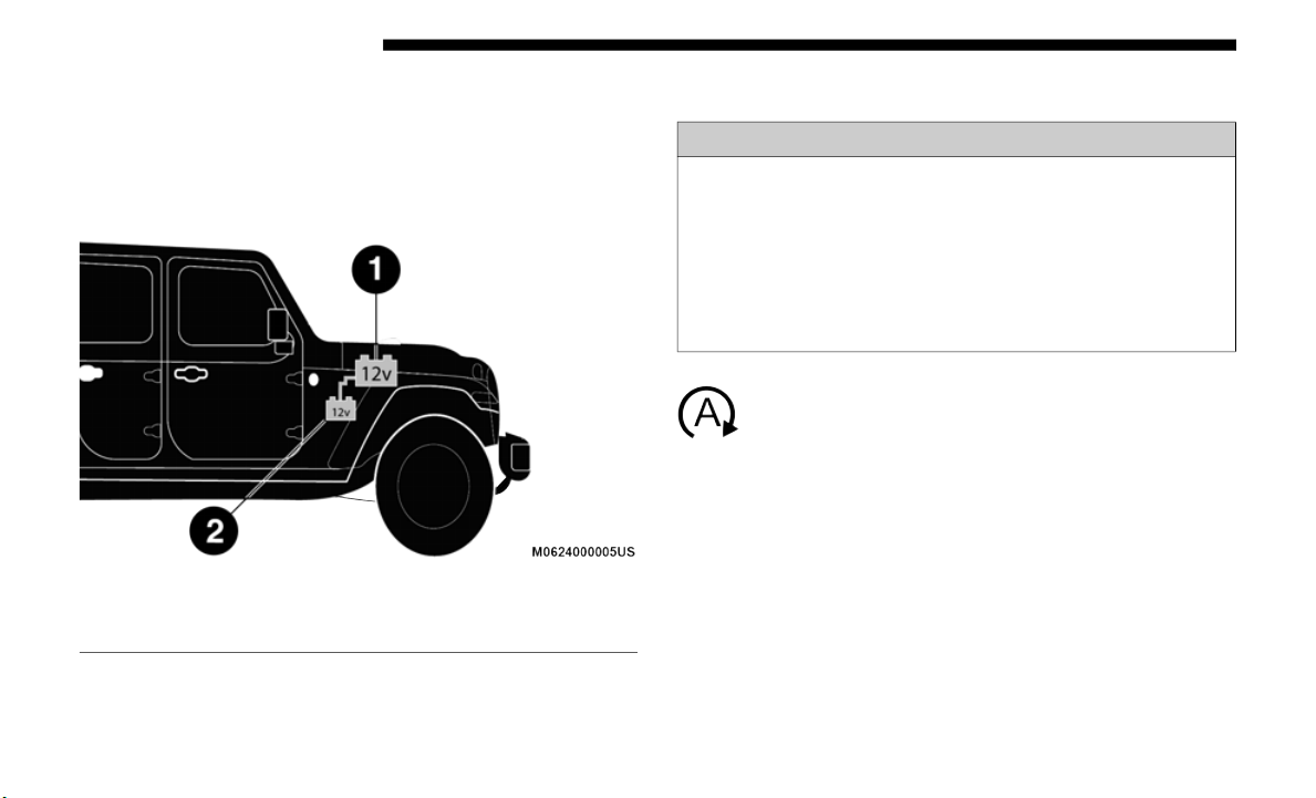
342 STARTING AND OPERATING
Secondary Battery
Your vehicle may be equipped with a secondary battery used
to power
the Stop/Start system and the 12 volt vehicle elec-
trical system. The secondary battery is located behind the
wh
eel well
for the front passenger wheel.
Battery Locations
Automatic Mode
The Stop/Start feature is enabled after every normal
customer engine start. At that time, the system will
go into S
TOP/START READY and if all other condi-
tions are met, can go into a STOP/START AUTOSTOP
A
CTIVE “
Autostop” mode.
1 — Primary Battery
2 — Secondary Battery
WARNING!
• Vehicles with the Stop/Start system will be equipped
with tw
o batteries. Both the main and the supplemental
batteries must be disconnected to completely de-ener
-
gize the 12 volt electrical system.
• S
erious injury or death could result if you do not
disconne
ct both batteries. To learn how to properly
disconnect, see your authorized dealer.

STARTING AND OPERATING 343
To Activate The Autostop Mode, The Following Must
Occur:
• The system must be in STOP/START READY state. A
STOP/ST
ART READY message will be displayed in the
instrument cluster display within the Stop/Start section.
Refer to “Instrument Cluster” in “Getting To Know Your
Instrument Panel” for further information.
• The vehicle must be completely stopped.
• The sh
ifter must be in a forward gear and the brake pedal
depres
sed.
The engine will shut down, the tachometer will move to the
zero po
sition and the Stop/Start telltale will illuminate indi-
cating you are in Autostop. Customer settings will be main-
tained upon return to an engine running condition.
Possible Reasons The Engine Does Not Autostop
Prior to engine shut down, the system will check many safety
and comfort conditions to see if they are fulfilled. Detailed
information about the operation of the Stop/Start system
may be viewed in the instrument cluster display Stop/Start
Screen. In the following situations, the engine will not stop:
• Driver’s seat belt is not buckled.
• Driver
’s door is not closed.
• Batter
y temperature is too warm or cold.
• Batter
y charge is low.
• The ve
hicle is on a steep grade.
• Cabin
heating or cooling is in process and an acceptable
cabin
temperature has not been achieved.
• HVAC is set to full defrost mode at a high blower speed.
• HVAC s
et to MAX A/C.
• Engine
has not reached normal operating temperature.
• Engine
temperature too high.
• The tr
ansmission is not in a forward gear.
• Hood i
s open.
• Transf
er case is in 4LO or Neutral.
• Brake p
edal is not pressed with sufficient pressure.
5

344 STARTING AND OPERATING
Other Factors Which Can Inhibit Autostop Include:
• Accelerator pedal input.
• Vehicl
e speed threshold not achieved from previous
auto-s
top.
• Steering angle beyond threshold. (ESS Models Only)
• ACC is
on and speed is set.
• Vehicl
e is at high altitude.
• System
fault present.
It may
be possible for the vehicle to be driven several times
without
the STOP/START system going into a STOP/
START READY state under more extreme conditions of the
items listed above.
To Start The Engine While In Autostop Mode
While in a forward gear, the engine will start when the brake
pedal is released or the throttle pedal is depressed. The trans-
mission will automatically re-engage upon engine restart.
Conditions That Will Cause The Engine To Start Automat-
ically While In Autostop Mode:
• T
he transmission selector is moved out of DRIVE.
• To mai
ntain cabin temperature comfort.
• Actual
cabin temperature is significantly different than
temper
ature set on Auto HVAC.
• HVAC is set to full defrost mode.
• HVAC s
ystem temperature or fan speed is manually
adjust
ed.
• Battery voltage drops too low.
• Low bra
ke vacuum (e.g. after several brake pedal applica-
tions)
.
• S
TOP/START OFF switch is pushed.
• A STOP
/START system error occurs.
• STOP/ST
ART AUTO STOP ACTIVE time exceeds
5 minut
es.
• 4
WD system is put into 4LO or Neutral mode.
• Steeri
ng wheel is turned beyond threshold. (ESS Models
Only)
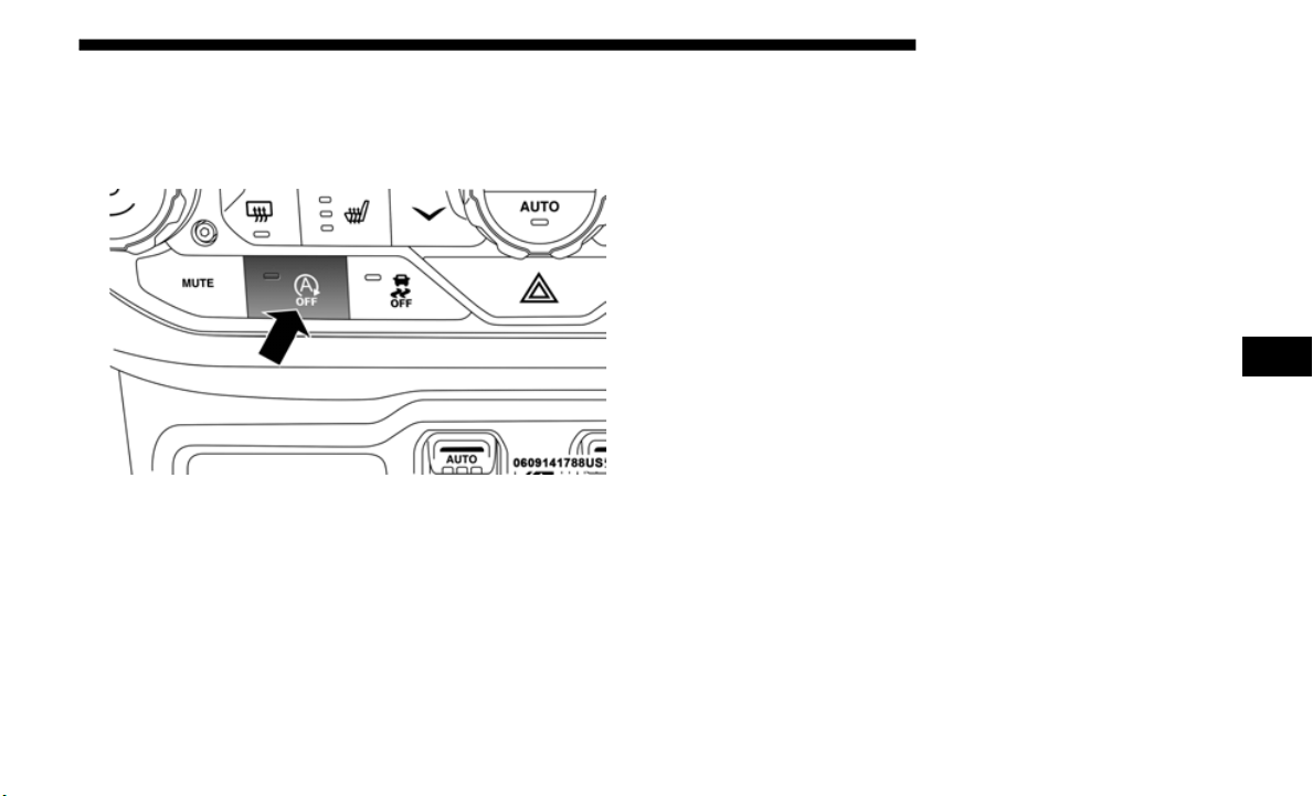
STARTING AND OPERATING 345
To Manually Turn Off The Stop/Start System
1. Push the STOP/START OFF switch (located on the
switch bank). The light on the switch will illuminate.
STOP/START Off Switch
2. The “STOP/START OFF” message will appear in instru-
ment cl
uster display within the Stop/Start section. Refer
to “Inst
rument Cluster” in “Getting To Know Your
Instrument Panel” for further information.
3. At the next vehicle stop (after turning off the STOP/
START s
ystem), the engine will not be stopped.
4. The STOP/START system will reset itself back to an ON
conditi
on every time the ignition is turned off and back on.
To Manually Turn On The Stop/Start System
Push the STOP/START OFF switch (located on the switch
bank). The light on the switch will turn off.
System Malfunction
If there is a malfunction in the STOP/START system, the
system will not shut down the engine. A “SERVICE STOP/
START SYSTEM” message will appear in the instrument
cluster display. Refer to “Instrument Cluster Display“ in
“Getting to Know Your Instrument Panel” for further infor
-
mation.
If the “SERVICE STOP/START SYSTEM” message appears
in the i
nstrument cluster display, have the system checked
by an authorized dealer.
5
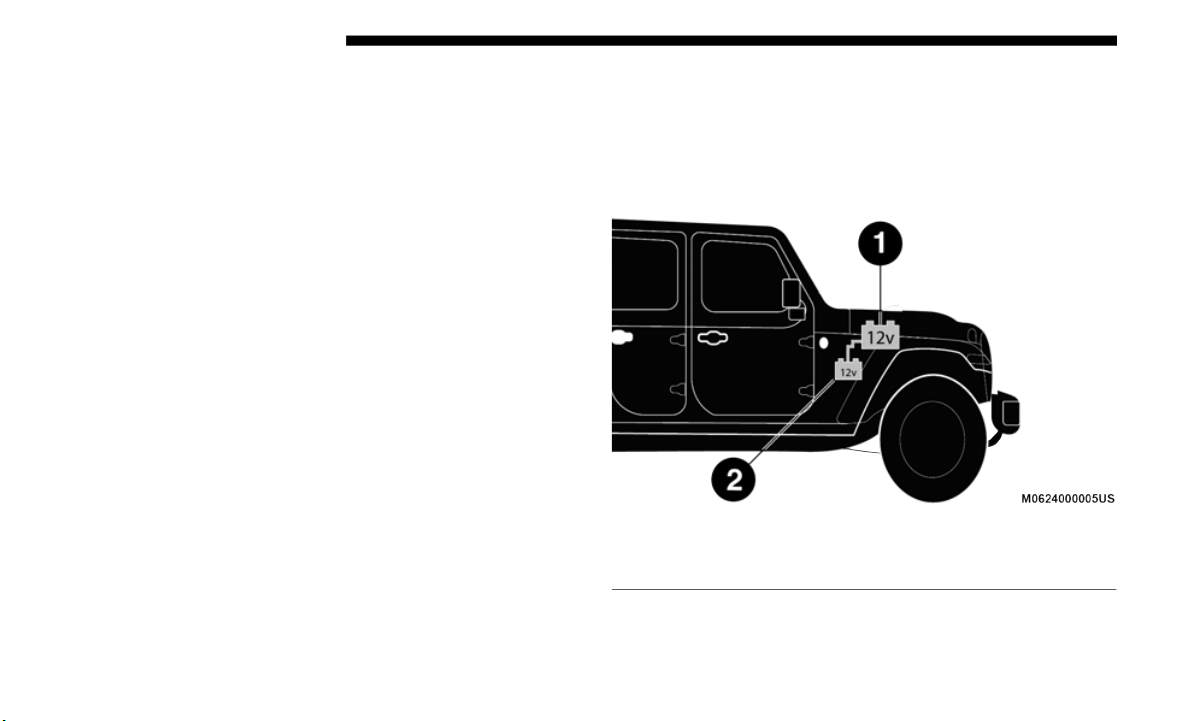
346 STARTING AND OPERATING
STOP/START SYSTEM — MANUAL TRANSMISSION
(IF EQUIPPED)
The Stop/Start function is developed to reduce fuel
consumption. The system will stop the engine automatically
during a vehicle stop if the required conditions are met.
Pressing the clutch pedal will automatically restart the
vehicle.
ESS vehicles have been upgraded with a heavy duty starter,
enhanced
battery, and other upgraded engine parts, to
handle the additional engine starts. Vehicles equipped with
eTorque contain a heavy duty motor generator and an addi
-
tional hybrid electric battery to store energy from vehicle
d
ecelera
tion for use on engine startup after a stop as well as
providing launch torque assist.
NOTE:
It is recommended that the Start/Stop System be disabled
during of
f-road use.
Secondary Battery
Your vehicle may be equipped with a secondary battery used
to power
the Stop/Start system and the 12 volt vehicle elec-
trical system. The secondary battery is located behind the
wh
eel well
for the front passenger wheel.
Battery Locations
1 — Primary Battery
2 — Secondary Battery

STARTING AND OPERATING 347
Automatic Mode
The Stop/Start feature is enabled after every normal
customer engine start. It will remain in STOP/
START NO
T READY until you drive forward with a
vehicle speed greater than 5
mph (8 km/h). At that time, the
system wil
l go into STOP/START READY and if all other
conditions are met, can go into an STOP/START AUTO
STOP ACTIVE mode.
To Activate The STOP/START AUTO STOP ACTIVE
Mode, The
Following Must Occur:
• The system must be in STOP/START READY state. A
STOP/STA
RT READY message will be displayed in the
instrument cluster. Refer to “Instrument Cluster Display”
in “Getting To Know Your Instrument Panel” for further
information.
• Vehicle speed must be less than 2 mph (3
km/h).
• The gear selector must be in the NEUTRAL position and
the clu
tch pedal must be fully released
The engine will shut down, the tach
ometer will fall to the
Stop/Start position, the STOP/START AUTO STOP
ACTIVE message will appear, and the heater/air condi
-
tioning (HVAC) air flow will be reduced.
WARNING!
• Vehicles with the Stop/Start system will be equipped
with tw
o batteries. Both the main and the supplemental
batteries must be disconnected to completely de-ener
-
gize the 12 volt electrical system.
• S
erious injury or death could result if you do not
disconne
ct both batteries. To learn how to properly
disconnect, see your authorized dealer.
5

348 STARTING AND OPERATING
Possible Reasons The Engine Does Not Autostop
Prior to engine shut down, the system will check many safety
and comfort conditions to see if they are fulfilled. In
following situations the engine will not stop:
• Driver’s seat belt is not buckled.
• Outsid
e temperature is less than 10°F (–12°C) or greater
than 1
09°F (43°C).
• Actual cabin temperature is significantly different than
temper
ature set on Auto HVAC.
• HVAC is set to full defrost mode.
• Engine
has not reached normal operating temperature.
• Batter
y discharged.
• When d
riving in REVERSE.
• Hood i
s open.
• Transf
er case is in 4LO or Neutral
• Driver
's seat is not occupied or driver door is open.
• Vehicl
e is at high altitude.
• The v
ehicle is on a steep grade.
• Forward
Gear is engaged.
• Steeri
ng angle beyond threshold. (ESS Models Only)
• System
fault is present.
• HVAC s
et to MAX A/C.
It may
be possible for the vehicle to be driven several times
without
the STOP/START system going into a STOP/
START READY state under more extreme conditions of the
items listed above.
To Start The Engine While In Autostop Mode
When the gear selector is in NEUTRAL, the engine will start
when the clutch pedal is pressed (does not require complete/
full pedal press). The vehicle will go into STOP/START
SYSTEM NOT READY mode until the vehicle speed is
greater than 5
mph (8 km/h).
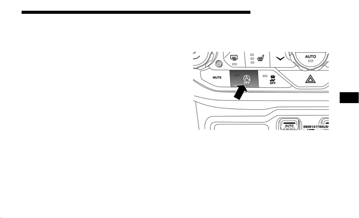
STARTING AND OPERATING 349
Conditions that will cause the engine to start automatically
while in STOP/START AUTO STOP ACTIVE mode
The Engine Will Start Automatically When:
• A
ctual cabin temperature is significantly different than
tempera
ture set on Auto HVAC.
• HVAC is set to full defrost mode.
• STOP/STA
RT AUTO STOP ACTIVE time exceeds
5 minute
s.
• B
attery voltage drops too low.
• Low brake
vacuum e.g. after several brake pedal applica-
tions.
• V
e
hicle is moving faster than 5 mph (8
km/h).
• STOP/START OFF switch is pressed.
• 4WD syst
em is put into 4LO or Neutral mode.
• Steerin
g wheel is turned beyond threshold. (ESS Models
Only)
To Manually Turn Off The Start/Stop System
1. Push the STOP/START Off switch (located on the switch
bank). The light on the switch will illuminate.
STOP/START Off Switch
2. The STOP/START OFF message will appear in the
instrum
ent cluster. Refer to “Instrument Cluster Display”
in “Getting To Know Your Instrument Panel” for further
information.
3. At the next vehicle stop (after turning off the STOP/
START s
ystem), the engine will not be stopped.
5
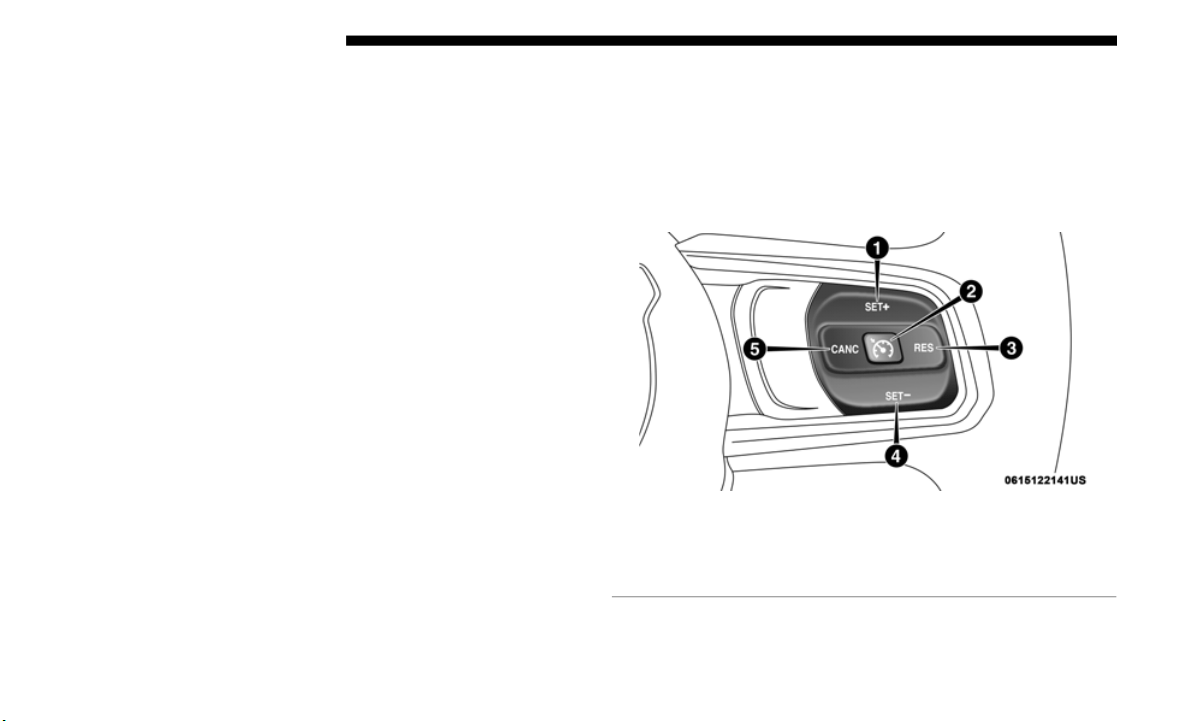
350 STARTING AND OPERATING
4. If the STOP/START system is manually turned off, the
engine can only be started and stopped by cycling the
ignition switch.
5. The STOP/START system will reset itself back to an ON
conditi
on every time the ignition is turned off and back on.
To Manually Turn On The Stop/Start System
Push the STOP/START OFF switch (located on the switch
bank). The light on the switch will turn off.
System Malfunction
If there is a malfunction in the STOP/START system, the
system will not shut down the engine. A “SERVICE STOP/
START SYSTEM” message will appear in the instrument
cluster display. Refer to “Instrument Cluster Display“ in
“Getting to Know Your Instrument Panel” for further infor
-
mation.
If the “SERVICE STOP/START SYSTEM” message appears
in the i
nstrument cluster display, have the system checked
by an authorized dealer.
SPEED CONTROL — IF EQUIPPED
When engaged, the Speed Control takes over accelerator
operations at speeds greater than 20 mph (32 km/h).
The Speed Control buttons are located on the right side of the
steering
wheel.
Speed Control Buttons
1 — SET (+)/Accel 4 — SET (-)/Decel
2 — On/Off 5 — CANC/Cancel
3 — RES/Resume

STARTING AND OPERATING 351
NOTE:
• In order to ensure proper operation, the Speed Control
System
has been designed to shut down if multiple Speed
Control functions are operated at the same time. If this
occurs, the Speed Control System can be reactivated by
pushing the Speed Control on/off button and resetting the
desired vehicle set speed.
To Activate
Push the On/Off button to activate the Speed Control. The
cruise indicator light in the instrument cluster display will
illuminate. To turn the system off, push the On/Off button a
second time. The cruise indicator light will turn off. The
system should be turned off when not in use.
To Set A Desired Speed
Turn the Speed Control on.
NOTE:
The vehicle should be traveling at a steady speed and on
level gr
ound before pushing the SET (+) or SET (-) button.
When the vehicle has reached the desired speed, push the
SET (+)
or SET (-) button and release. Release the accelerator
and the vehicle will operate at the selected speed.
WARNING!
Speed Control can be dangerous where the system
cannot m
aintain a constant speed. Your vehicle could go
too fast for the conditions, and you could lose control
and have an accident. Do not use Speed Control in heavy
traffic or on roads that are winding, icy, snow-covered or
slippery.
WARNING!
Leaving the Speed Control system on when not in use is
dangerous
. You could accidentally set the system or
cause it to go faster than you want. You could lose
control and have an accident. Always leave the system
off when you are not using it.
5

352 STARTING AND OPERATING
To Vary The Speed Setting
To Increase Speed
When the Speed Control is set, you can increase speed by
pushing
the SET (+) button.
The driver’s preferred units can be selected through the
i
n
strum
ent panel settings. Refer to ”Instrument Cluster
Display” in “Getting To Know Your Instrument Panel” for
more information. The speed increment shown is dependent
on the chosen speed unit of U.S. (mph) or Metric (km/h):
U.S. Speed (mph)
• Pushing the SET (+) butt
on once will result in a 1 mph
increase in set speed. Each subsequent tap of the button
results in an increase of 1
mph.
• If the button is continually pushed, the set speed will
contin
ue to increase until the button is released, then the
new set speed will be established.
Metric Speed (km/h)
• Pushing the SET (+) butt
on once will result in a 1 km/h
increase in set speed. Each subsequent tap of the button
results in an increase of 1
km/h.
• If the button is continually pushed, the set speed will
contin
ue to increase until the button is released, then the
new set speed will be established.
To Decrease Speed
When the Speed Control is set, you can decrease speed by
pushing
the SET (-) button.
The driver’s preferred units can be selected through the
instrum
ent panel settings. Refer to ”Instrument Cluster
Display” in “Getting To Know Your Instrument Panel” for
more information. The speed increment shown is dependent
on the chosen speed unit of U.S. (mph) or Metric (km/h):
U.S. Speed (mph)
• Pushing the SET (-) but
ton once will result in a 1 mph
decrease in set speed. Each subsequent tap of the button
results in a decrease of 1
mph.
• If the button is continually pushed, the set speed will
contin
ue to decrease until the button is released, then the
new set speed will be established.

STARTING AND OPERATING 353
Metric Speed (km/h)
• Pushing the SET (-) but
ton once will result in a 1 km/h
decrease in set speed. Each subsequent tap of the button
results in a decrease of 1
km/h.
• If the button is continually pushed, the set speed will
contin
ue to decrease until the button is released, then the
new set speed will be established.
To Accelerate For Passing
Press the accelerator as you would normally. When the pedal
is released, the vehicle will return to the set speed.
Using Speed Control On Hills
The transmission may downshift on hills to maintain the
vehicle
set speed.
NOTE:
The Speed Control system maintains speed up and down
h
ills.
A slight speed change on moderate hills is normal.
On steep hills, a greater speed loss or gain may occur so it
may be p
referable to drive without Speed Control.
To Resume Speed
To resume a previously set speed, push the RES button and
release. Resume can be used at any speed above 20 mph
(32 km/h).
To Deactivate
A soft tap on the brake pedal, pushing the CANC (cancel)
button, or normal brake pressure while slowing the vehicle
will deactivate the speed control without erasing the set
speed from memory.
Pushing the on/off button or cycling the ignition to OFF,
erases
the set speed from memory.
WARNING!
Speed Control can be dangerous where the system
cannot m
aintain a constant speed. Your vehicle could go
too fast for the conditions, and you could lose control
and have an accident. Do not use Speed Control in heavy
traffic or on roads that are winding, icy, snow-covered or
slippery.
5

354 STARTING AND OPERATING
ADAPTIVE CRUISE CONTROL (ACC) — IF EQUIPPED
Adaptive Cruise Control (ACC) increases the driving conve-
nience provided by cruise control while traveling on high-
ways and major roadways. However, it is not a safety system
a
nd not
designed to prevent collisions. Speed Control func-
tion performs differently. Please refer to the proper section
w
ithin
this chapter.
ACC will allow you to keep cruise control engaged in light
to mode
rate traffic conditions without the constant need to
reset your cruise control. ACC utilizes a radar sensor and a
forward facing camera designed to detect a vehicle directly
ahead of you.
NOTE:
• If the sensor does not detect a vehicle ahead of you, ACC
will ma
intain a fixed set speed.
• If the ACC sensor detects a vehicle ahead, ACC will apply
limite
d braking or accelerate (not to exceed the original set
speed) automatically to maintain a preset following
distance, while matching the speed of the vehicle ahead.
The Cruise Control system has two control modes:
• Adaptive Cruise Control mode for maintaining an appro-
priate
distance between vehicles.
• N
ormal (Fixed Speed) Cruise Control mode for cruising at
a cons
tant preset speed. For additional information, refer
to “Normal (Fixed Speed) Cruise Control Mode” in this
section.
NOTE:
Normal (Fixed Speed) Cruise Control will not react to
p
recedi
ng vehicles. Always be aware of the mode selected.
You can change the mode by using the Cruise Control
buttons
. The two control modes function differently. Always
confirm which mode is selected.

STARTING AND OPERATING 355
(Continued)
WARNING!
• Adaptive Cruise Control (ACC) is a convenience
system.
It is not a substitute for active driving involve-
ment. It is always the driver’s responsibility to be atten-
tive of road, traffic, and weather conditions, vehicle
s
peed,
distance to the vehicle ahead; and, most impor-
tantly, brake operation to ensure safe operation of the
ve
hicle
under all road conditions. Your complete atten-
tion is always required while driving to maintain safe
c
ontrol of
your vehicle. Failure to follow these warn-
ings can result in a collision and death or serious
p
ersonal
injury.
• The ACC system:
• Does not
react to pedestrians, oncoming vehicles,
and st
ationary objects (e.g., a stopped vehicle in a
traffic jam or a disabled vehicle).
• Cannot take street, traffic, and weather conditions
into ac
count, and may be limited upon adverse sight
distance conditions.
• Does not always fully recognize complex driving
conditi
ons, which can result in wrong or missing
distance warnings.
• On vehicles with automatic transmission, will bring
the vehicle to a complete stop while following a
target vehicle and hold the vehicle for 2 seconds in
the stop position. If the target vehicle does not start
moving within two seconds the ACC system will
display a message that the system will release the
brakes and that the brakes must be applied manu
-
ally. An audible chime will sound when the brakes
are rel
eased.
You should switch off the ACC system:
• When driving in fog, heavy rain, heavy snow, sleet,
heavy t
raffic, and complex driving situations (i.e., in
highway construction zones).
• When entering a turn lane or highway off ramp; when
driving
on roads that are winding, icy, snow-covered,
slippery, or have steep uphill or downhill slopes.
• When towing a trailer up or down steep slopes.
• When c
ircumstances do not allow safe driving at a
constan
t speed.
WARNING! (Continued)
5

356 STARTING AND OPERATING
Activating Adaptive Cruise Control (ACC)
You can only engage ACC if the vehicle speed is above
0 mph (0 km/h).
The minimum set speed for the ACC system is 20 mph
(32 km/h).
W
hen the system is turned on and in the ready state, the
i
n
strum
ent cluster displays “ACC Ready.”
When the system is off, the instrument cluster displays
“Adapti
ve Cruise Control (ACC) Off.”
NOTE:
You cannot engage ACC under the following conditions:
• W
hen in Four-Wheel Drive Low.
• When yo
u apply the brakes.
• When t
he parking brake is applied.
• When t
he automatic transmission is in PARK, REVERSE or
NEUTRA
L.
• When the manual transmission is in first gear.
• When t
he vehicle speed is below 20 mph (
32 km/h)
(manual transmission).
• When the vehicle speed is outside of the speed range.
• When t
he brakes are overheated.
• When t
he driver’s door is open at low speeds.
• When t
he driver’s seat belt is unbuckled at low speeds.
• ESC Ful
l-Off Mode is active.
To Activate/Deactivate
Push and release the Adaptive Cruise Control (ACC) on/off
button. The ACC menu in the instrument cluster displays
“ACC Ready.”
Adaptive Cruise Control Ready
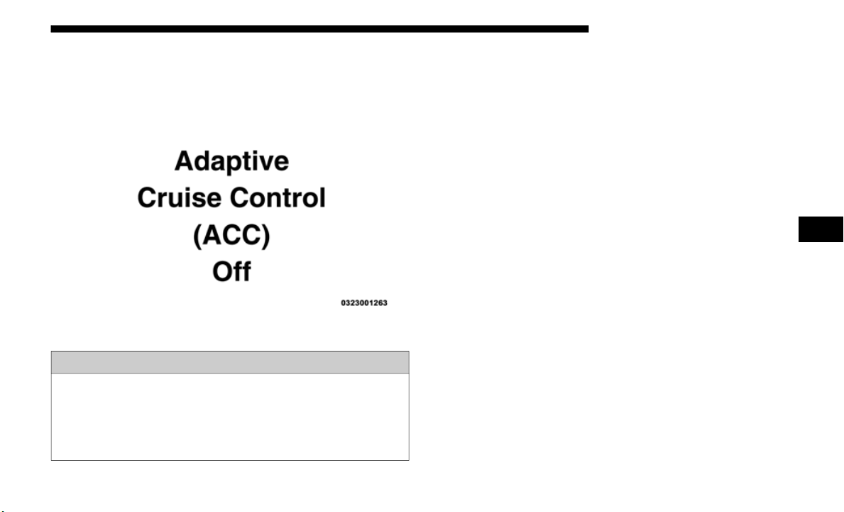
STARTING AND OPERATING 357
To turn the system off, push and release the Adaptive Cruise
Control (ACC) on/off button again. At this time, the system
will turn off and the instrument cluster displays “Adaptive
Cruise Control (ACC) Off.”
Adaptive Cruise Control Off
To Set A Desired ACC Speed
When the vehicle reaches the speed desired, push the SET (+)
button or the SET (-) button and release. The instrument
cluster display will display the set speed.
If the system is set when the vehicle speed is below 20 mph
(32 km/h),
the set speed shall be defaulted to 20 mph
(32 km/h).
If the system is set when the vehicle speed is
above 2
0 mph (32 km/h), the set speed shall be the current
speed o
f the vehicle. On vehicles equipped with a manual
transmission, the system cannot be set when the vehicle
speed is below 20
mph (32 km/h) or when the vehicle is in
first ge
ar.
NOTE:
ACC cannot be set if there is a stationary vehicle in front of
yo
ur veh
icle in close proximity.
Remove your foot from the accelerator pedal. If you do not,
the veh
icle may continue to accelerate beyond the set speed.
If this occurs:
• The message “DRIVER OVERRIDE” will display in the
instru
ment cluster display.
• The system will not be controlling the distance between your
vehicl
e and the vehicle ahead. The vehicle speed will only be
determined by the position of the accelerator pedal.
WARNING!
Leaving the Adaptive Cruise Control (ACC) system on
when not
in use is dangerous. You could accidentally set
the system or cause it to go faster than you want. You
could lose control and have a collision. Always leave the
system off when you are not using it.
5

358 STARTING AND OPERATING
To Cancel
The following conditions cancel the system:
• The brake pedal is applied.
• The CA
NC button is pushed.
• An Ant
i-Lock Brake System (ABS) event occurs.
• The gea
r selector is removed from the DRIVE position.
• The El
ectronic Stability Control/Traction Control System
(ESC/TC
S) activates.
• The vehicle parking brake is applied.
• Driver
seatbelt is unbuckled at low speeds.
• Driver
door is opened at low speeds.
• The br
aking temperature exceeds normal range (over-
heated
).
• A
Trailer Sway Control (TSC) event occurs.
• The ve
hicle speed is less than 15 mph (
24 km/h) (manual
transmission only).
• The clutch is depressed for more than ten seconds (manual
transm
ission only).
• The vehicle is placed in NEUTRAL for more than ten
second
s (manual transmission only).
To Turn Off
The system will turn off and clear the set speed in memory if:
• The Adaptive Cruise Control (ACC) on/off button is
pushed
.
• The Normal (Fixed Speed) Cruise Control on/off button is
pushed
.
• The ignition is turned OFF.
• You swi
tch to Four-Wheel Drive Low.
To Resume
If there is a set speed in memory push the RES (resume)
button and then remove your foot from the accelerator pedal.
The instrument cluster display will display the last set speed.
NOTE:
• If your vehicle stays at standstill for longer than two
second
s, then the system will cancel and the brake force
will be ramped-out. The driver will have to apply the
brakes to keep the vehicle at a standstill.
• ACC cannot be resumed if there is a stationary vehicle
in-fro
nt of your vehicle in close proximity.

STARTING AND OPERATING 359
To Vary The Speed Setting
To Increase Speed
While ACC is set, you can increase the set speed by pushing
the SET
(+) button.
The driver's preferred units can be selected through the
instrum
ent panel settings. Refer to “Getting To Know Your
Instrument Panel” for more information. The speed incre
-
ment shown is dependant on the chosen speed unit of U.S.
(mph) o
r Metric (km/h):
U.S. Speed (mph)
• Pushing the SET (+) butt
on once will result in a 1 mph
increase in set speed. Each subsequent tap of the button
results in an increase of 1
mph.
• If the button is continually pushed, the set speed will
contin
ue to increase in 5 mph increments until the button
is rele
ased. The increase in set speed is reflected in the
instrument cluster display.
Metric Speed (km/h)
• Pushing the SET (+) butt
on once will result in a 1 km/h
increase in set speed. Each subsequent tap of the button
results in an increase of 1
km/h.
• If the button is continually pushed, the set speed will
contin
ue to increase in 10 km/h increments until the
button
is released. The increase in set speed is reflected in
the instrument cluster display.
WARNING!
The Resume function should only be used if traffic and
road cond
itions permit. Resuming a set speed that is too
high or too low for prevailing traffic and road conditions
could cause the vehicle to accelerate or decelerate too
sharply for safe operation. Failure to follow these
warnings can result in a collision and death or serious
personal injury.
5

360 STARTING AND OPERATING
To Decrease Speed
While ACC is set, the set speed can be decreased by pushing
the SET
(-) button.
The driver's preferred units can be selected through the
i
n
strum
ent panel settings. Refer to “Getting To Know Your
Instrument Panel” for more information. The speed decre
-
ment shown is dependant on the chosen speed unit of U.S.
(mph) o
r Metric (km/h):
U.S. Speed (mph)
• P
ushing the SET (-) but
ton once will result in a 1 mph
decrease in set speed. Each subsequent tap of the button
results in a decrease of 1
mph.
• If the button is continually pushed, the set speed will
contin
ue to decrease in 5 mph decrements until the button
is rele
ased. The decrease in set speed is reflected in the
instrument cluster display.
Metric Speed (km/h)
• Pushing the SET (-) but
ton once will result in a 1 km/h
decrease in set speed. Each subsequent tap of the button
results in a decrease of 1
km/h.
• If the button is continually pushed, the set speed will
contin
ue to decrease in 10 km/h decrements until the
button
is released. The decrease in set speed is reflected in
the instrument cluster display.
NOTE:
• W
hen you override and push the SET (+) button or SET (-)
button
s, the new set speed will be the current speed of the
vehicle.
• When you use the SET (-) button to decelerate, if the
engine’s
braking power does not slow the vehicle suffi-
ciently to reach the set speed, the brake system will auto-
matically slow the vehicle.
• T
he ACC system applies the brake down to a full stop
when fo
llowing a target vehicle. If an ACC host vehicle
follows a target vehicle to a standstill, the host vehicle will
release the vehicle brakes two seconds after coming to a
full stop.
• The ACC system maintains set speed when driving up hill
and do
wn hill. However, a slight speed change on
moderate hills is normal. In addition, downshifting may
occur while climbing uphill or descending downhill. This
is normal operation and necessary to maintain set speed.
When driving up hill and down hill, the ACC system will
cancel if the braking temperature exceeds normal range
(overheated).
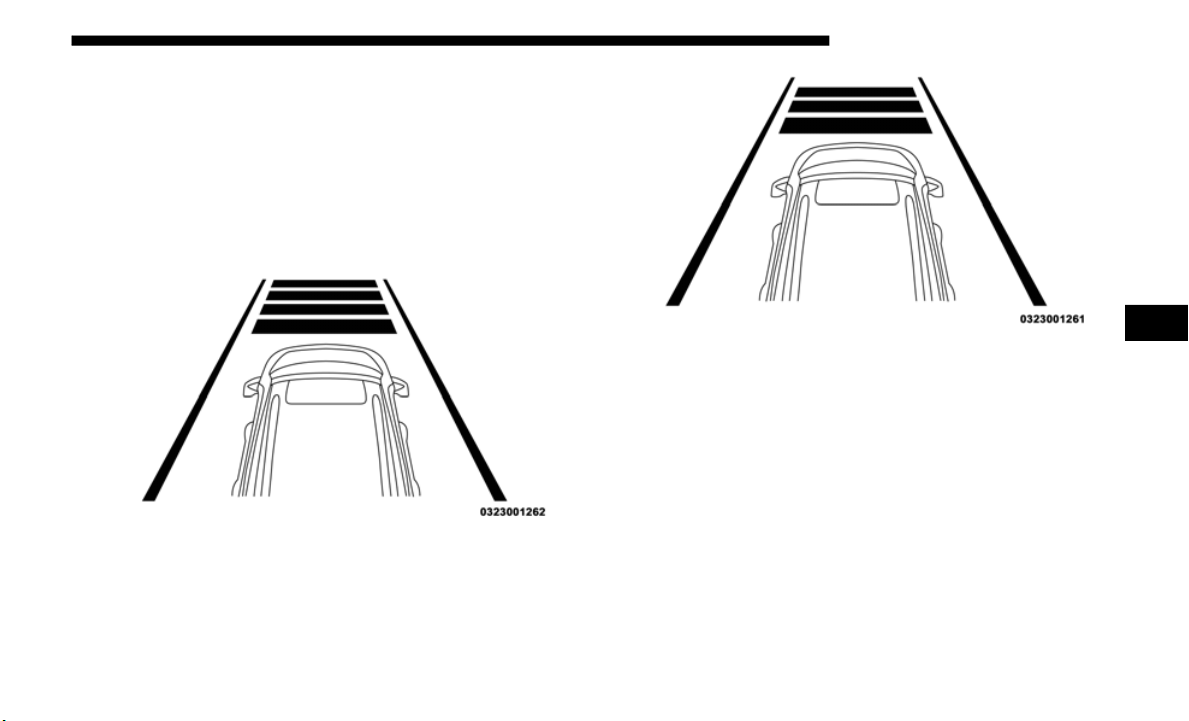
STARTING AND OPERATING 361
Setting The Following Distance In ACC
The specified following distance for ACC can be set by
varying the distance setting between four bars (longest),
three bars (long), two bars (medium) and one bar (short).
Using this distance setting and the vehicle speed, ACC calcu
-
lates and sets the distance to the vehicle ahead. This distance
s
etting
displays in the instrument cluster display.
Distance Setting 4 Bars (Longest)
Distance Setting 3 Bars (Long)
5
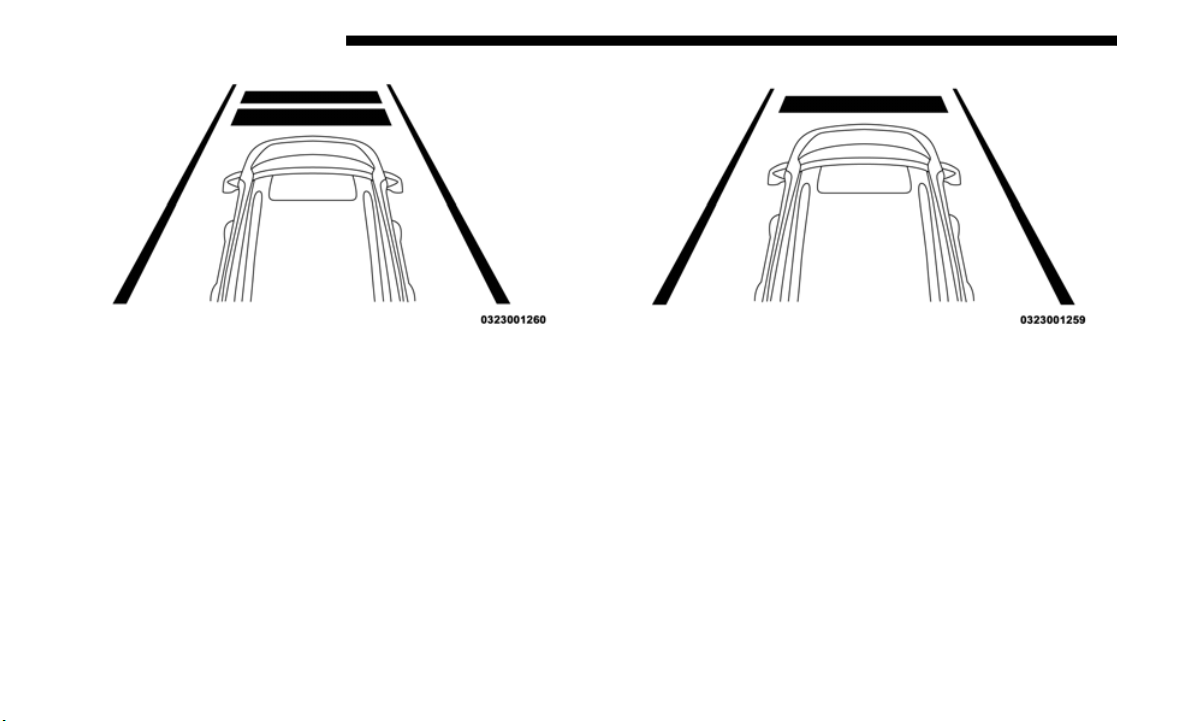
362 STARTING AND OPERATING
Distance Setting 2 Bars (Medium) Distance Setting 1 Bar (Short)
To increase the distance setting, push the Distance Setting —
Increas
e button and release. Each time the button is pushed,
the distance setting increases by one bar (longer).
To decrease the distance setting, push the Distance Setting —
Decreas
e button and release. Each time the button is pushed,
the distance setting decreases by one bar (shorter).
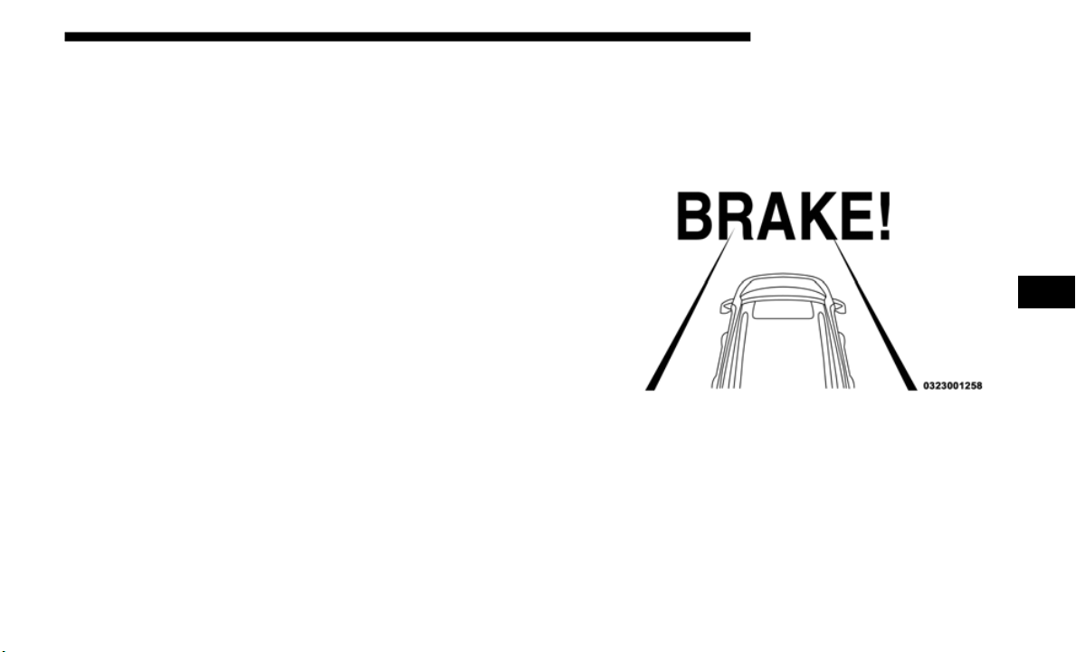
STARTING AND OPERATING 363
If there is no vehicle ahead, the vehicle will maintain the set
speed. If a slower moving vehicle is detected in the same
lane, the instrument cluster displays the “Sensed Vehicle
Indicator” icon, and the system adjusts vehicle speed auto
-
matically to maintain the distance setting, regardless of the
s
et spe
ed.
The vehicle will then maintain the set distance until:
• T
he vehicle ahead accelerates to a speed above the set
speed.
•
The vehicle ahead moves out of your lane or view of the
sensor
.
• The distance setting is changed.
• The sys
tem disengages. (Refer to the information on ACC
Activa
tion).
The maximum braking applied by ACC is limited; however,
the dri
ver can always apply the brakes manually, if neces-
sary.
NOTE:
The brake lights will illuminate whenever the ACC system
a
pplies
the brakes.
A Proximity Warning will alert the driver if ACC predicts
that it
s maximum braking level is not sufficient to maintain
the set distance. If this occurs, a visual alert “BRAKE” will
flash in the instrument cluster display and a chime will
sound while ACC continues to apply its maximum braking
capacity.
Brake Alert
NOTE:
The “Brake!” Screen in the instrument cluster display is a
warning f
or the driver to take action and does not necessarily
mean that the Forward Collision Warning system is
applying the brakes autonomously.
5

364 STARTING AND OPERATING
Overtake Aid
When driving with ACC engaged and following a vehicle,
the system will provide an additional acceleration up to the
ACC set speed to assist in passing the vehicle. This addi
-
tional acceleration is triggered when the driver utilizes the
left tu
rn signal and will only be active when passing on the
left hand side.
ACC Operation At A Stop (Automatic Transmission
Only)
If the ACC system brings your vehicle to a standstill while
following a target vehicle, if the target vehicle starts moving
within two seconds of your vehicle coming to a standstill,
your vehicle will resume motion without the need for any
driver action.
If the target vehicle does not start moving within two
seconds
of your vehicle coming to a standstill, the ACC with
Stop system will cancel and the brakes will release. A cancel
message will display on the instrument cluster display and
produce a warning chime. Driver intervention will be
required at this moment.
While ACC with Stop is holding your vehicle at a standstill,
if the
driver seatbelt is unbuckled or the driver door is
opened, the ACC with Stop system will cancel and the brakes
will release. A cancel message will display on the instrument
cluster display and produce a warning chime. Driver inter
-
vention will be required at this moment.
Adaptive Cruise Control (ACC) Menu
The instrument cluster display will show the current ACC
system settings. The instrument cluster display is located in
the center of the instrument cluster. The information it
displays depends on ACC system status.
Push the Adaptive Cruise Control (ACC) on/off button
(locate
d on the steering wheel) until one of the following
appears in the instrument cluster display:
Adaptive Cruise Control Off
When ACC is deactivated, the display will read “Adaptive
Cruise
Control Off.”
WARNING!
When the ACC system is resumed, the driver must
ensure
that there are no pedestrians, vehicles or objects
in the path of the vehicle. Failure to follow these
warnings can result in a collision and death or serious
personal injury.

STARTING AND OPERATING 365
Adaptive Cruise Control Ready
When ACC is activated, but the vehicle speed setting has not
been se
lected, the display will read “Adaptive Cruise
Control Ready.”
Adaptive Cruise Control Set
When the SET (+) or the SET (-) button (located on the
steerin
g wheel) is pushed, the display will read “ACC SET.”
When ACC is set, the set speed will show in the instrument
cluster
display.
The ACC screen may display once again if any ACC activity
occurs,
which may include any of the following:
• System Cancel
• Driver
Override
• System
Off
• ACC Pr
oximity Warning
• ACC Un
available Warning
The in
strument cluster display will return to the last
display
selected after five seconds of no ACC display
activity
Display Warnings And Maintenance
“Wipe Front Radar Sensor In Front Of Vehicle” Warning
The “ACC/FCW Unavailable Wipe Front Radar Sensor”
warning wi
ll display and also a chime will indicate when
conditions temporarily limit system performance.
This most often occurs at times of poor visibility, such as in
snow or
heavy rain. The ACC system may also become
temporarily blinded due to obstructions, such as mud, dirt or
ice. In these cases, the instrument cluster display will display
“ACC/FCW Unavailable Wipe Front Radar Sensor” and the
system will deactivate.
The “ACC/FCW Unavailable Wipe Front Radar Sensor”
message
can sometimes be displayed while driving in highly
reflective areas (i.e. tunnels with reflective tiles, or ice and
snow). The ACC system will recover after the vehicle has left
these areas. Under rare conditions, when the radar is not
tracking any vehicles or objects in its path this warning may
temporarily occur.
5

366 STARTING AND OPERATING
NOTE:
If the “ACC/FCW Unavailable Wipe Front Radar Sensor”
warning i
s active Normal (Fixed Speed) Cruise Control is
still available. For additional information refer to “Normal
(Fixed Speed) Cruise Control Mode” in this section.
If weather conditions are not a factor, the driver should
examine
the sensor. It may require cleaning or removal of an
obstruction. The sensor is located in the center of the vehicle
behind the lower grille.
To keep the ACC System operating properly, it is important
to note
the following maintenance items:
• Always keep the sensor clean. Carefully wipe the sensor
lens wi
th a soft cloth. Be cautious not to damage the sensor
lens.
• Do not remove any screws from the sensor. Doing so could
cause
an ACC system malfunction or failure and require a
sensor realignment.
• If the sensor or front end of the vehicle is damaged due to
a coll
ision, see your authorized dealer for service.
• Do not attach or install any accessories near the sensor,
includ
ing transparent material or aftermarket grilles.
Doing so could cause an ACC system failure or malfunc
-
tion.
When the condition that deactivated the system is no longer
present
, the system will return to the “Adaptive Cruise
Control Off” state and will resume function by simply reac
-
tivating it.
NOTE:
• I
f the “ACC/FCW Unavailable Wipe Front Radar Sensor”
message
occurs frequently (e.g. more than once on every
trip) without any snow, rain, mud, or other obstruction,
have the radar sensor realigned at your authorized dealer.
• Installing a snow plow, front-end protector, an after-
market
grille or modifying the grille is not recommended.
Doing so
may block the sensor and inhibit ACC/FCW
operation.

STARTING AND OPERATING 367
“Clean Front Windshield” Warning
The “ACC/FCW Limited Functionality Clean Front Wind-
shield” warning will display and also a chime will indicate
when con
ditions temporarily limit system performance. This
most often occurs at times of poor visibility, such as in snow
or heavy rain and fog. The ACC system may also become
temporarily blinded due to obstructions, such as mud, dirt,
or ice on windshield and fog on the inside of glass. In these
cases, the instrument cluster display will display “ACC/
FCW Limited Functionality Clean Front Windshield” and
the system will have degraded performance.
The “ACC/FCW Limited Functionality Clean Front Wind-
shield” message can sometimes be displayed while driving
in adve
rse weather conditions. The ACC/FCW system will
recover after the vehicle has left these areas. Under rare
conditions, when the camera is not tracking any vehicles or
objects in its path this warning may temporarily occur.
If weather conditions are not a factor, the driver should
examine
the windshield and the camera located on the back
side of the inside rear view mirror. They may require
cleaning or removal of an obstruction.
When the condition that created limited functionality is no
longer p
resent, the system will return to full functionality.
NOTE:
If the “ACC/FCW Limited Functionality Clean Front Wind-
shield” message occurs frequently (e.g. more than once on
e
very tr
ip) without any snow, rain, mud, or other obstruc-
tion, have the windshield and forward facing camera
i
nspect
ed at your authorized dealer.
Service ACC/FCW Warning
If the system turns off, and the instrument cluster displays
“
ACC/FCW
Unavailable Service Required” or “Cruise/
FCW Unavailable Service Required”, there may be an
internal system fault or a temporary malfunction that limits
ACC functionality. Although the vehicle is still drivable
under normal conditions, ACC will be temporarily unavail
-
able. If this occurs, try activating ACC again later, following
a
n ignit
ion cycle. If the problem persists, see your authorized
dealer.
5

368 STARTING AND OPERATING
Precautions While Driving With ACC
In certain driving situations, ACC may have detection issues.
In these cases, ACC may brake late or unexpectedly. The
driver needs to stay alert and may need to intervene.
NOTE:
• Do not put stickers or easy passes over the camera/radar
field
of view.
• Cracks in the windshield may affect the performance of
ACC, d
epending on the size and location of the crack.
ACC Sensor Protective Cover
Your vehicle is equipped with a protective cover that is to be
u
sed whe
never the windshield is folded down in order to
protect the ACC sensor. To install the cover, follow the
instructions below.
1. Secure the top part of the cover so that it hinges to the
header
.
2. Swing the cover down and push on it so that it covers the
openin
g.
3. Check to make sure the cover is secured properly.
NOTE:
Be
sure to remove the cover before returning the windshield
t
o the
normal position. Store the cover in the cargo area.
Cleaning Instructions
During windshield down applications, dust/dirt can accu-
mulate in the cover and block the camera lens. Use a micro-
fiber cloth to clean the camera lens, module, and inside
c
over,
being careful not to damage or scratch the module.
Towing A Trailer
Towing a trailer is not advised when using ACC.
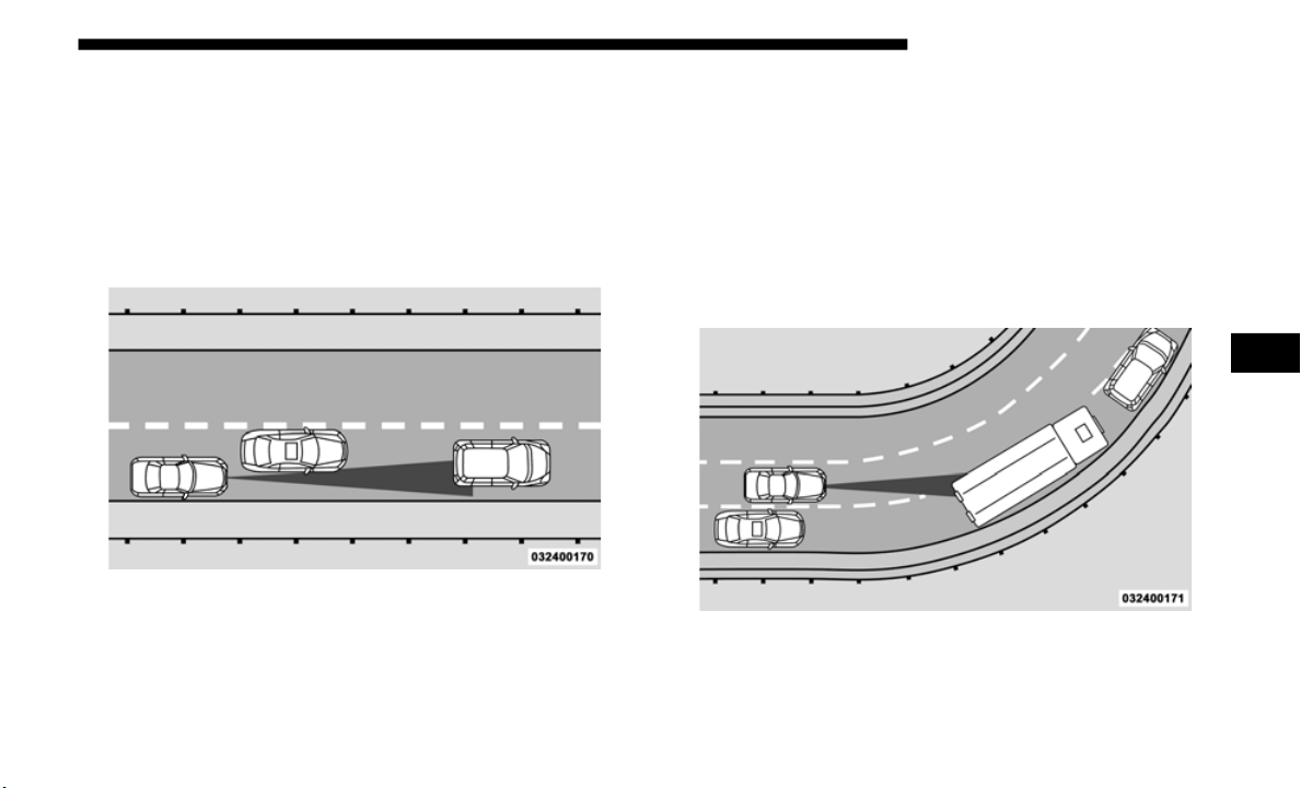
STARTING AND OPERATING 369
Offset Driving
ACC may not detect a vehicle in the same lane that is offset
from you
r direct line of travel, or a vehicle merging in from
a side lane. There may not be sufficient distance to the
vehicle ahead. The offset vehicle may move in and out of the
line of travel, which can cause your vehicle to brake or accel
-
erate unexpectedly.
Offset Driving Condition Example
Turns And Bends
When driving on a curve with ACC engaged, the system
may decrease the vehicle speed and acceleration for stability
reasons, with no target vehicle detected. Once the vehicle is
out of the curve the system will resume your original set
speed. This is a part of normal ACC system functionality.
NOTE:
On tight turns ACC performance may be limited.
Turn Or Bend Example
5
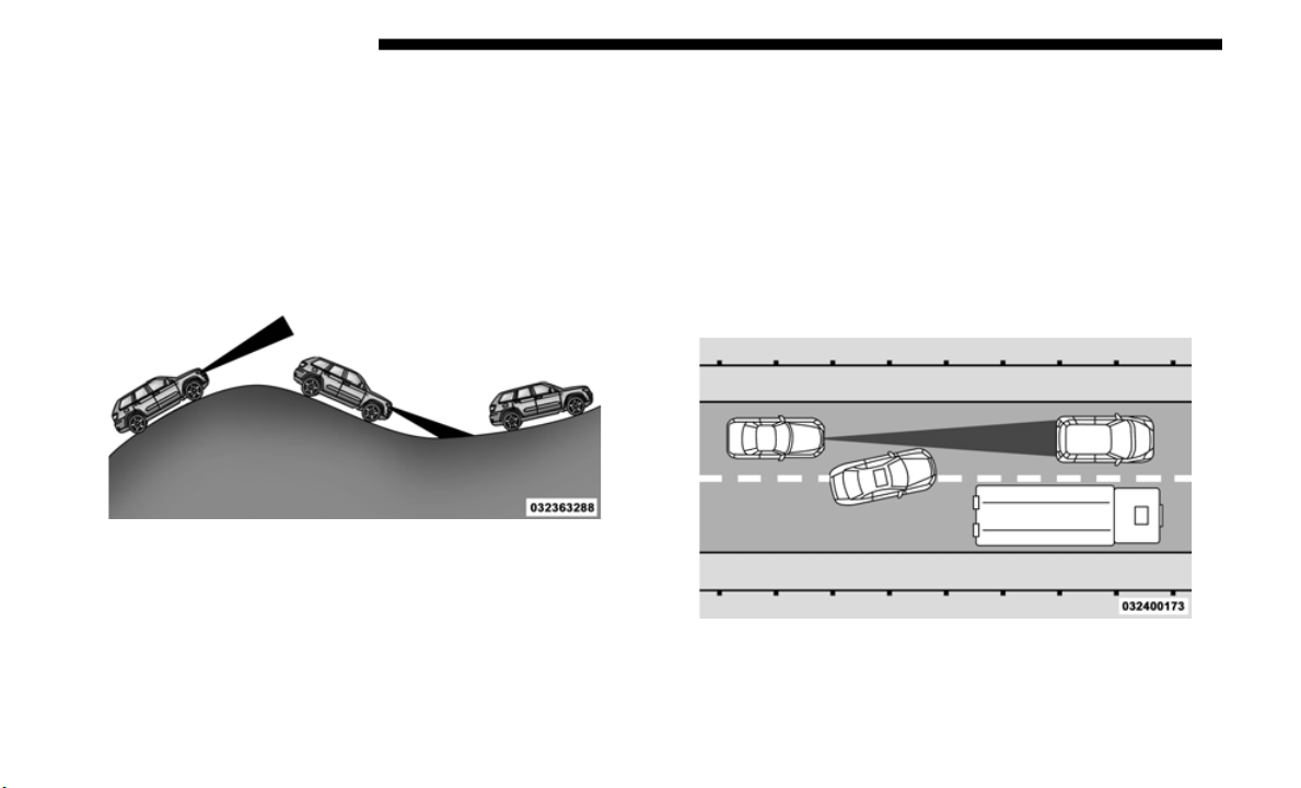
370 STARTING AND OPERATING
Using ACC On Hills
When driving on hills, ACC may not detect a vehicle in your
lane. D
epending on the speed, vehicle load, traffic condi-
tions, and the steepness of the hills, ACC performance may
b
e limi
ted.
ACC Hill Example
Lane Changing
ACC may not detect a vehicle until it is completely in the
lane in
which you are traveling. In the illustration shown,
ACC has not yet detected the vehicle changing lanes and it
may not detect the vehicle until it's too late for the ACC
system to take action. ACC may not detect a vehicle until it
is completely in the lane. There may not be sufficient
distance to the lane-changing vehicle. Always be attentive
and ready to apply the brakes if necessary.
Lane Changing Example
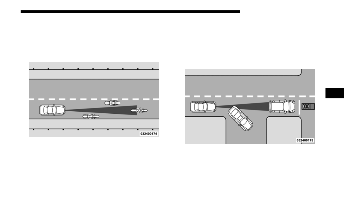
STARTING AND OPERATING 371
Narrow Vehicles
Some narrow vehicles traveling near the outer edges of the
lane or
edging into the lane are not detected until they have
moved fully into the lane. There may not be sufficient
distance to the vehicle ahead.
Narrow Vehicle Example
Stationary Objects And Vehicles
ACC does not react to stationary objects and stationary vehi-
cles. For example, ACC will not react in situations where the
vehicle
you are following exits your lane and the vehicle
ahead is stopped in your lane. Always be attentive and ready
to apply the brakes if necessary.
Stationary Object And Stationary Vehicle Example
5

372 STARTING AND OPERATING
General Information
The following regulatory statement applies to all Radio
Frequency (RF) devices equipped in this vehicle:
This device complies with Part 15 of the FCC Rules and with
Industr
y Canada license-exempt RSS standard(s). Operation
is subject to the following two conditions:
1. This device may not cause harmful interference.
2. This
device must accept any interference received,
includ
ing interference that may cause undesired operation.
NOTE:
Changes or modifications not expressly approved by the
party re
sponsible for compliance could void the user’s
authority to operate the equipment.
Normal (Fixed Speed) Cruise Control Mode
In addition to Adaptive Cruise Control mode, a Normal
(Fixed Speed) Cruise Control mode is available for cruising
at fixed speeds. The Normal (Fixed Speed) Cruise Control
mode is designed to maintain a set cruising speed without
requiring the driver to operate the accelerator. Cruise
Control can only be operated if the vehicle speed is above
20
mph (32 km/h).
To change between the different control modes, push the
Adaptiv
e Cruise Control (ACC) on/off button which turns
the ACC and the Normal (Fixed Speed) Cruise Control off.
Pushing the Normal (Fixed Speed) Cruise Control on/off
button will result in turning on (changing to) the Normal
(Fixed Speed) Cruise Control mode.
WARNING!
In the Normal (Fixed Speed) Cruise Control mode, the
system w
ill not react to vehicles ahead. In addition, the
proximity warning does not activate and no alarm will
sound even if you are too close to the vehicle ahead since
neither the presence of the vehicle ahead nor the
vehicle-to-vehicle distance is detected. Be sure to
maintain a safe distance between your vehicle and the
vehicle ahead. Always be aware which mode is selected.

STARTING AND OPERATING 373
To Set A Desired Speed
Turn the Normal (Fixed Speed) Cruise Control on.
When the vehicle has reached the desired speed,
push th
e SET (+) or SET (-) button and release.
Release the accelerator and the vehicle will operate at the
selected speed. Once a speed has been set a message
“CRUISE CONTROL SET TO MPH (km/h)” will appear
indicating what speed was set. This light will turn on when
the system is turned on via the on/off control. It turns green
when the cruise control is set.
To Vary The Speed Setting
To Increase Speed
When the Normal (Fixed Speed) Cruise Control is set, you
can inc
rease speed by pushing the SET (+) button.
The driver's preferred units can be selected through the
instrum
ent cluster display. Refer to “Getting To Know Your
Instrument Panel” for more information. The speed incre
-
ment shown is dependant on the speed of U.S. (mph) or
Metric
(km/h) units:
U.S. Speed (mph)
• P
ushing the SET (+) butt
on once will result in a 1 mph
increase in set speed. Each subsequent tap of the button
results in an increase of 1
mph.
• If the button is continually pushed, the set speed will
contin
ue to increase in 5 mph increments until the button
is rele
ased. The increase in set speed is reflected in the
instrument cluster display.
Metric Speed (km/h)
• Pushing the SET (+) butt
on once will result in a 1 km/h
increase in set speed. Each subsequent tap of the button
results in an increase of 1
km/h.
• If the button is continually pushed, the set speed will
contin
ue to increase in 10 km/h increments until the
button
is released. The increase in set speed is reflected in
the instrument cluster display.
5

374 STARTING AND OPERATING
To Decrease Speed
When the Normal (Fixed Speed) Cruise Control is set, you
can dec
rease speed by pushing the SET (-) button.
The driver's preferred units can be selected through the
i
n
strum
ent cluster display. Refer to “Getting To Know Your
Instrument Panel” for more information. The speed decre
-
ment shown is dependant on the speed of U.S. (mph) or
Metric
(km/h) units:
U.S. Speed (mph)
• P
ushing the SET (-) but
ton once will result in a 1 mph
decrease in set speed. Each subsequent tap of the button
results in a decrease of 1
mph.
• If the button is continually pushed, the set speed will
contin
ue to decrease in 5 mph decrements until the button
is rele
ased. The decrease in set speed is reflected in the
instrument cluster display.
Metric Speed (km/h)
• Pushing the SET (-) but
ton once will result in a 1 km/h
decrease in set speed. Each subsequent tap of the button
results in a decrease of 1
km/h.
• If the button is continually pushed, the set speed will
contin
ue to decrease in 10 km/h decrements until the
button
is released. The decrease in set speed is reflected in
the instrument cluster display.
To Cancel
The following conditions will cancel the Normal (Fixed
Speed)
Cruise Control without clearing the memory:
• The brake pedal is applied.
• The CA
NC button is pushed.
• The El
ectronic Stability Control/Traction Control System
(ESC/TC
S) activates.
• The vehicle parking brake is applied.
• The br
aking temperature exceeds normal range (over-
heated
).
• T
he gear selector is removed from the DRIVE position.
• The dr
iver switches ESC to full-off mode.

STARTING AND OPERATING 375
To Resume Speed
To resume a previously set speed, push the RES button and
release
. Resume can be used at any speed above 20 mph
(32 km/h).
T
o Turn Off
The system will turn off and erase the set speed in memory if:
• T
he Normal (Fixed Speed) Cruise Control on/off button is
pushed
.
• The ignition is turned OFF.
• You en
gage Four-Wheel Drive Low.
• The Ad
aptive Cruise Control (ACC) on/off button is
pushed
.
PARKSENSE REAR PARK ASSIST — IF EQUIPPED
The ParkSense Rear Park Assist system provides visual and
audible indications of the distance between the rear fascia
and a detected obstacle when backing up, e.g. during a
parking maneuver. Refer to “ParkSense System Usage
Precautions” in this section for limitations of this system and
recommendations.
ParkSense will retain the last system state (enabled or
disable
d) from the last ignition cycle when the ignition is
changed to the ON/RUN position.
ParkSense can be active only when the gear selector is in
REVERSE
. If ParkSense is enabled at this gear selector posi-
tion, the system will remain active until the vehicle speed is
i
ncreas
ed to approximately 7 mph (11 km/h) or above.
When in
REVERSE and above the system's operating speed,
a warning will appear within the instrument cluster display
indicating the vehicle speed is too fast. The system will
become active again if the vehicle speed is decreased to
speeds less than approximately 6
mph (9 km/h).
ParkSense Sensors
The four ParkSense sensors, located in the rear fascia/bumper,
monitor the area behind the vehicle that is within the sensors’
field of view. The sensors can detect obstacles from approxi
-
mately 12 inches (30 cm) up to 79 inches (200 cm) from the rear
fascia/
bumper in the horizontal direction, depending on the
location, type and orientation of the obstacle.
5
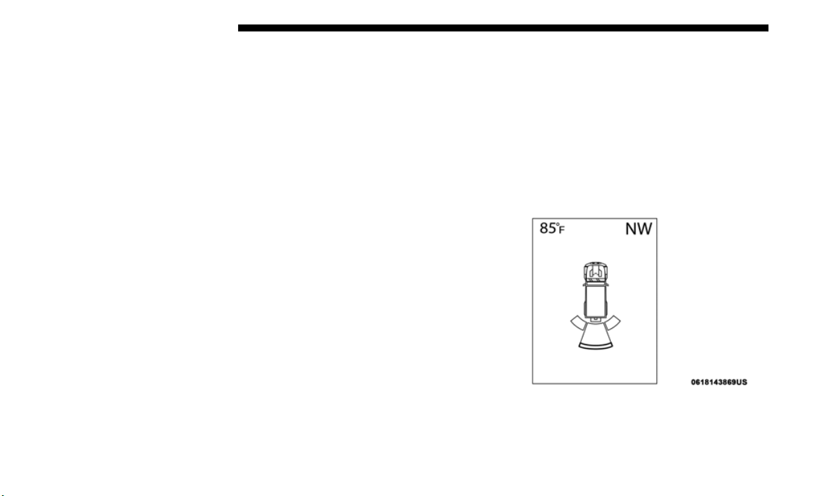
376 STARTING AND OPERATING
ParkSense Warning Display
The ParkSense Warning screen will only be displayed if
“Sound and Display” is selected from the Customer -
Programmable Features section of the Uconnect System.
Refer to "Uconnect Settings” in “Multimedia” for further
information.
The ParkSense Warning screen is located within the instru-
ment cluster display. It provides visual warnings to indicate
the dist
ance between the rear fascia/bumper and the
detected obstacle. Refer to “Instrument Cluster Display” in
“Getting To Know Your Instrument Panel” for further infor
-
mation.
ParkSense Display
When the vehicle is in REVERSE, the instrument cluster
display will show the park assist ready system status.
The system will indicate a detected obstacle by showing a
single ar
c in one or more regions based on the obstacle’s
distance and location relative to the vehicle.
If an obstacle is detected in the center rear region, the display
will show
a single solid arc in the center rear region and will
produce a one-half second tone. As the vehicle moves closer
to the obstacle, the display will show the single arc moving
closer to the vehicle and the sound tone will change from
slow, to fast, to continuous.
If an obstacle is detected in the left and/or right rear region,
the disp
lay will show a single flashing arc in the left and/or
right rear region and will produce a fast sound tone. As the
vehicle moves closer to the obstacle, the display will show
the single arc moving closer to the vehicle and the tone will
change from fast to continuous.
Single 1/2 Second Tone/Solid Arc
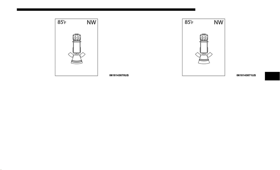
STARTING AND OPERATING 377
Slow Tone/Solid Arc Slow Tone/Solid Arc
5
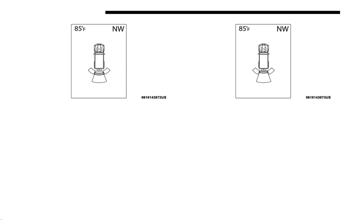
378 STARTING AND OPERATING
Fast Tone/Flashing Arc Continuous Tone/Flashing Arc

STARTING AND OPERATING 379
The vehicle is close to the obstacle when the warning display shows one flashing arc and sounds a continuous tone. The
following chart shows the warning alert operation when the system is detecting an obstacle:
NOTE:
ParkSense will reduce the volume of the radio, if on, when
t
he syst
em is sounding an audio tone.
WARNING ALERTS
Rear Distance
(inches
/cm)
Greater than
79 inche
s
(200 cm
)
79-59 inches
(200-15
0 cm)
59-47 inches
(150-120 cm)
47-39 inches
(120-100 cm)
39-25 inches
(100-65 cm)
25-12 inches
(65-30 cm)
Less than
12 inche
s
(30 cm)
A
rcs — Left None None None None None 2nd Flashing 1st Flashing
Arcs —
Center
No
ne 6th Solid 5th Solid 4th Solid 3rd Flashing 2nd Flashing 1st Flashing
Arcs — Right None None None None None 2nd Flashing 1st Flashing
Audible Alert
Chime
Non
e
Single 1/2-
Second
Tone
(for rear
center
only)
Slow
(for rear
center
only)
Slow
(for rear
center only)
Fast
(for rear
center only)
Fast Continuous
Radio
Volume
R
educed
No Yes Yes Yes Yes Yes Yes
5
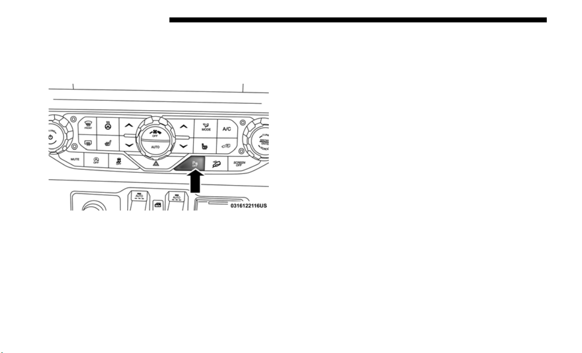
380 STARTING AND OPERATING
Enabling And Disabling ParkSense
ParkSense can be enabled and disabled with the ParkSense
switch, located on the switch panel below the climate controls.
ParkSense Switch
When the ParkSense switch is pushed to disable the system,
the inst
rument cluster display will show the “PARKSENSE
OFF” message for approximately five seconds. Refer to
“Instrument Cluster Display” in “Getting To Know Your
Instrument Panel” for further information. When the gear
selector is moved to REVERSE and the system is disabled, the
instrument cluster display will show the “PARKSENSE OFF”
message for as long as the vehicle is in REVERSE (Not in 4LO).
The ParkSense switch LED will be on when ParkSense is
disabled
or requires service. The ParkSense switch LED will
be off when the system is enabled. If the ParkSense switch is
pushed, and requires service, the ParkSense switch LED will
blink momentarily, and then the LED will be on.
Service The ParkSense Rear Park Assist System
During vehicle start up, when the ParkSense Rear Park
Assist System has detected a faulted condition, the instru-
ment cluster display will actuate a single chime, once per
ignition
cycle, and it will display the “PARKSENSE
UNAVAILABLE WIPE REAR SENSORS” or the “PARK-
SENSE UNAVAILABLE SERVICE REQUIRED” message.
Refer to
“Instrument Cluster Display”. When the gear
selector is moved to REVERSE and the system has detected a
faulted condition, the instrument cluster display will show
the "PARKSENSE UNAVAILABLE WIPE REAR SENSORS"
or "PARKSENSE UNAVAILABLE SERVICE REQUIRED"
message for as long as the vehicle is in REVERSE. Under this
condition, ParkSense will not operate.
If “PARKSENSE UNAVAILABLE WIPE REAR SENSORS”
appears
in the instrument cluster display, make sure the
outer surface and the underside of the rear fascia/bumper is
clean and clear of snow, ice, mud, dirt or other obstruction
and then cycle the ignition. If the message continues to
appear, see an authorized dealer.

STARTING AND OPERATING 381
If “PARKSENSE UNAVAILABLE SERVICE REQUIRED”
appears in the instrument cluster display, see an authorized
dealer.
Cleaning The ParkSense System
Clean the Rear Park Assist sensors with water, car wash soap
and a soft cloth. Do not use rough or hard cloths. In washing
stations, clean sensors quickly keeping the vapor jet/high
pressure washing nozzles at least 4
inches (10 cm) from the
sensors
. Do not scratch or poke the sensors. Otherwise, you
could damage the sensors.
ParkSense System Usage Precautions
NOTE:
• Ensure that the rear bumper is free of snow, ice, mud, dirt
and de
bris to keep the ParkSense system operating properly.
• Jackhammers, large trucks, and other vibrations could
affect
the performance of ParkSense.
• When you turn ParkSense OFF, the instrument cluster
displa
y will read “PARKSENSE OFF.” Furthermore, once
you turn ParkSense OFF, it remains off until you turn it on
again, even if you cycle the ignition.
• ParkSense, when on, will reduce the volume of the radio
when it
is sounding a tone.
• Clean the ParkSense sensors regularly, taking care not to
scratc
h or damage them. The sensors must not be covered
with ice, snow, slush, mud, dirt or debris. Failure to do so
can result in the system not working properly. The Park
-
Sense system might not detect an obstacle behind the
f
ascia/b
umper, or it could provide a false indication that
an obstacle is behind the fascia/bumper.
• Use the ParkSense switch to turn the ParkSense system
OFF if o
bjects such as bicycle carriers, trailer hitches, etc.
are placed within 12
inches (30 cm) from the rear fascia/
bumper.
Failure to do so can result in the system misinter-
preting a close object as a sensor problem, causing the
“
PARKSE
NSE UNAVAILABLE SERVICE REQUIRED”
message to be displayed in the instrument cluster display.
• The operation of the rear sensors is automatically deacti-
vated
when the trailer's electric plug is inserted in the
vehicle
's tow hook socket. The rear sensors are automati-
cally reactivated when the trailer's cable plug is removed.
5

382 STARTING AND OPERATING
PARKVIEW REAR BACK UP CAMERA
The ParkView Rear Back Up Camera allows you to see an
on-screen image of the rear surroundings of your vehicle
whenever the gear selector is put into REVERSE. The image
will be displayed in the touchscreen display along with a
caution note to “check entire surroundings” across the top of
the screen. After five seconds this note will disappear. The
ParkView camera is located on the rear of the vehicle in the
center of the spare tire.
WARNING!
• Drivers must be careful when backing up even when
using P
arkSense. Always check carefully behind your
vehicle, look behind you, and be sure to check for
pedestrians, animals, other vehicles, obstructions, and
blind spots before backing up. You are responsible for
safety and must continue to pay attention to your
surroundings. Failure to do so can result in serious
injury or death.
• Before using ParkSense, it is strongly recommended
that t
he ball mount and hitch ball assembly is discon-
nected from the vehicle when the vehicle is not used for
t
owing. Fa
ilure to do so can result in injury or damage
to vehicles or obstacles because the hitch ball will be
much closer to the obstacle than the rear fascia when
the loudspeaker sounds the continuous tone. Also, the
sensors could detect the ball mount and hitch ball
assembly, depending on its size and shape, giving a
false indication that an obstacle is behind the vehicle.
CAUTION!
• ParkSense is only a parking aid and it is unable to
recogni
ze every obstacle, including small obstacles.
Parking curbs might be temporarily detected or not
detected at all. Obstacles located above or below the
sensors will not be detected when they are in close
proximity.
• The vehicle must be driven slowly when using Park-
Sense
in order to be able to stop in time when an
obstacle
is detected. It is recommended that the driver
looks over his/her shoulder when using ParkSense.

STARTING AND OPERATING 383
Manual Activation Of The Rear View Camera
1. Press the “Controls” button located on the bottom of the
Uconne
ct display.
2. P
ress the “Backup Camera” button to turn the Rear View
C
amera
system on.
When the vehicle is shifted out of REVERSE (with Camera
delay tu
rned off), the rear Camera mode is exited and the
previous screen appears again.
When the vehicle is shifted out of REVERSE (with Camera
delay tu
rned on), the rear Camera image will be displayed
for up to 10 seconds unless the vehicle speed exceeds 8
mph
(13 km/h),
the transmission is shifted into PARK, the igni-
tion is switched to the OFF position, or the touchscreen
b
utton
“X” to disable display of the Rear View Camera
image is pressed.
Whenever the Rear View Camera image is activated through the
"Backup
Camera" button in the "Controls" menu, and the vehicle
speed is greater than, or equal to, 8
mph (13 km/h), a display
timer fo
r the image is initiated. The image will continue to be
displayed until the display timer exceeds 10 seconds.
NOTE:
• If the vehicle speed remains below 8 mph (
13 km/h), the
Rear View Camera image will be displayed continuously
until deactivated via the touchscreen button "X", the trans
-
mission is shifted into PARK, or the ignition is cycled to
the OFF p
osition.
• The touchscreen button "X" to disable display of the
camera
image is made available ONLY when the vehicle is
not in REVERSE.
When enabled, active guide lines are overlaid on the image
to illu
strate the width of the vehicle and its projected backup
path based on the steering wheel position. A dashed center
line overlay indicates the center of the vehicle to assist with
parking or aligning to a hitch/receiver.
When enabled, fixed guide lines are overlaid on the image to
illustr
ate the width of the vehicle.
Different colored zones indicate the distance to the rear of
the veh
icle.
5
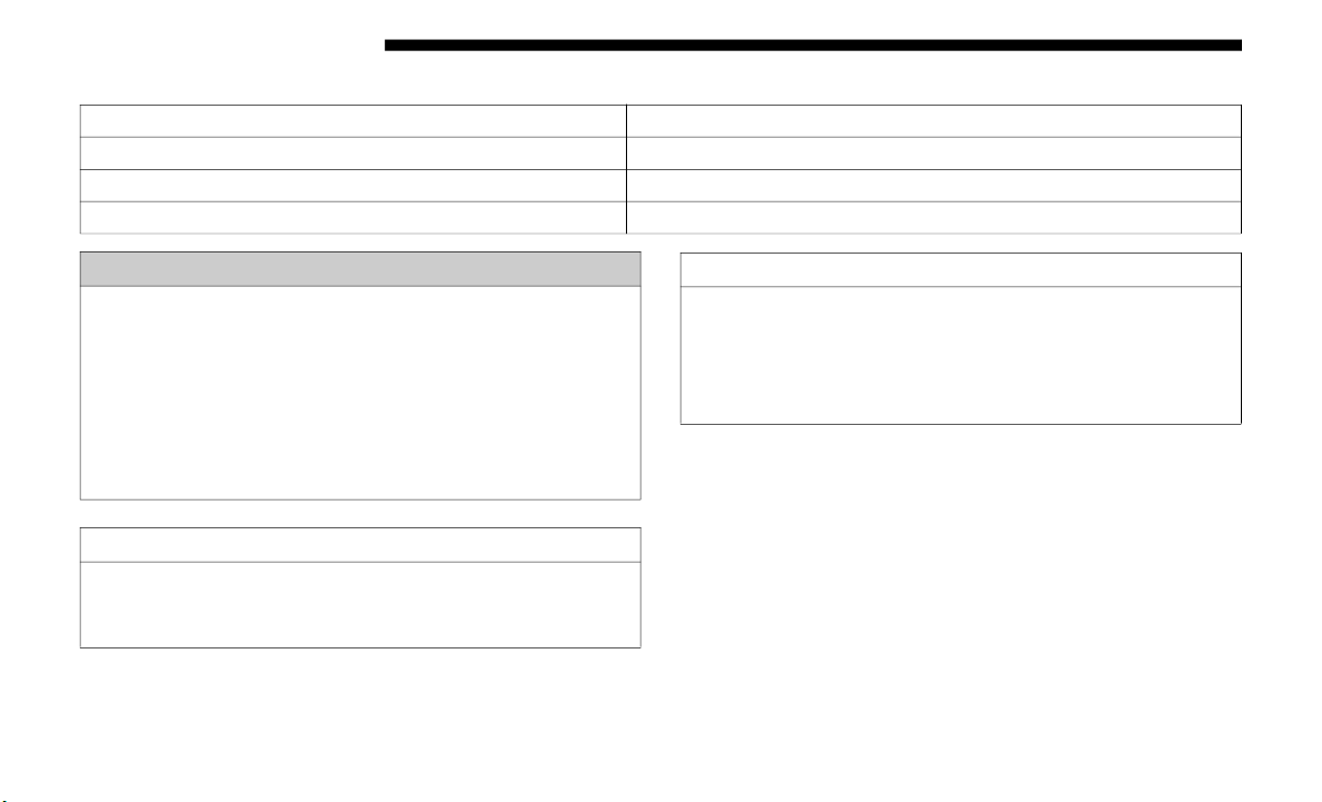
384 STARTING AND OPERATING
(Continued)
The following table shows the approximate distances for each zone:
NOTE:
If snow, ice, mud, or any foreign substance builds up on the
c
amera
lens, clean the lens, rinse with water, and dry with a
soft cloth. Do not cover the lens.
Zone Distance To The Rear Of The Vehicle
Red 0 - 1 ft (0 - 30 cm)
Yellow 1 ft - 6.5 ft (30 cm - 2 m)
Green 6.5 ft or greater (2 m or greater)
WARNING!
Drivers must be careful when backing up even when
using th
e ParkView Rear Back Up Camera. Always check
carefully behind your vehicle, and be sure to check for
pedestrians, animals, other vehicles, obstructions, or
blind spots before backing up. You are responsible for
the safety of your surroundings and must continue to
pay attention while backing up. Failure to do so can
result in serious injury or death.
CAUTION!
• To avoid vehicle damage, ParkView should only be
used a
s a parking aid. The ParkView camera is unable
to view every obstacle or object in your drive path.
• To avoid vehicle damage, the vehicle must be driven
slowly when using ParkView to be able to stop in time
when an obstacle is seen. It is recommended that the
driver look frequently over his/her shoulder when
using ParkView.
CAUTION! (Continued)
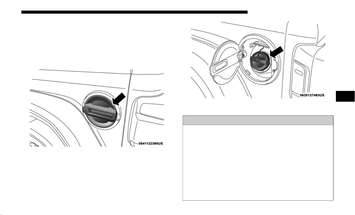
STARTING AND OPERATING 385
REFUELING THE VEHICLE
Fuel Filler Cap
The fuel filler cap is located on the driver's side of the vehicle.
If the fuel filler cap is lost or damaged, be sure the replace-
ment cap is the correct one for this vehicle.
Fuel Filler Door
Fuel Filler Cap
WARNING!
• Never have any smoking materials lit in or near the
vehicle
when the fuel door is open or the tank is being
filled.
• Never add fuel when the engine is running. This is in
violation
of most state and federal fire regulations and
may cause the “Malfunction Indicator Light” to turn on.
• A fire may result if fuel is pumped into a portable
containe
r that is inside of a vehicle. You could be
burned. Always place fuel containers on the ground
while filling.
5

386 STARTING AND OPERATING
NOTE:
• When the fuel nozzle “clicks” or shuts off, the fuel tank is
full.
• T
ighten the fuel filler cap about 1/4 turn until you hear one
click.
This is an indication that the cap is properly tight-
ened.
• I
f the fuel filler cap is not tightened properly, the MIL will
come o
n. Be sure the cap is tightened every time the
vehicle is refueled.
Loose Fuel Filler Cap Message
After fuel has been added, the vehicle diagnostic system can
determine if the fuel filler cap is possibly loose, improperly
installed, or damaged. If the system detects a malfunction,
the “gASCAP” message will display in the odometer
display. Tighten the gas cap until a "clicking" sound is heard.
This is an indication that the gas cap is properly tightened.
Push the odometer reset button to turn the message off. If the
problem persists, the message will appear the next time the
vehicle is started. This might indicate a damaged cap. If the
problem is detected twice in a row, the system will turn on
the MIL. Resolving the problem will turn the MIL off.
CAUTION!
• D
amage to the fuel system or emission control system
could r
esult from using an improper fuel filler cap. A
poorly fitting cap could let impurities into the fuel
system. Also, a poorly fitting aftermarket cap can cause
the “Malfunction Indicator Light (MIL)” to illuminate,
due to fuel vapors escaping from the system.
• To avoid fuel spillage and overfilling, do not “top off”
the fu
el tank after filling.

STARTING AND OPERATING 387
VEHICLE LOADING
Certification Label
As required by National Highway Traffic Safety Administra-
tion regulations, your vehicle has a certification label affixed
to the
driver's side door or pillar.
This label contains the month and year of manufacture,
G
r
oss V
ehicle Weight Rating (GVWR), Gross Axle Weight
Rating (GAWR) front and rear, and Vehicle Identification
Number (VIN). A Month-Day-Hour (MDH) number is
included on this label and indicates the Month, Day and
Hour of manufacture. The bar code that appears on the
bottom of the label is your VIN.
Gross Vehicle Weight Rating (GVWR)
The GVWR is the total permissible weight of your vehicle
includi
ng driver, passengers, vehicle, options and cargo. The
label also specifies maximum capacities of front and rear axle
systems (GAWR). Total load must be limited so GVWR and
front and rear GAWR are not exceeded.
Payload
The payload of a vehicle is defined as the allowable load
weight a
truck can carry, including the weight of the driver,
all passengers, options and cargo.
Gross Axle Weight Rating (GAWR)
The GAWR is the maximum permissible load on the front
and rea
r axles. The load must be distributed in the cargo area
so that the GAWR of each axle is not exceeded.
Each axle GAWR is determined by the components in the
system wi
th the lowest load carrying capacity (axle, springs,
tires or wheels). Heavier axles or suspension components
sometimes specified by purchasers for increased durability
does not necessarily increase the vehicle's GVWR.
Tire Size
The tire size on the Vehicle Certification Label represents the
actual
tire size on your vehicle. Replacement tires must be
equal to the load capacity of this tire size.
5

388 STARTING AND OPERATING
Rim Size
This is the rim size that is appropriate for the tire size listed.
Inflation Pressure
This is the cold tire inflation pressure for your vehicle for all
loading
conditions up to full GAWR.
Curb Weight
The curb weight of a vehicle is defined as the total weight of
the veh
icle with all fluids, including vehicle fuel, at full
capacity conditions, and with no occupants or cargo loaded
into the vehicle. The front and rear curb weight values are
determined by weighing your vehicle on a commercial scale
before any occupants or cargo are added.
Loading
The actual total weight and the weight of the front and rear
of your
vehicle at the ground can best be determined by
weighing it when it is loaded and ready for operation.
The entire vehicle should first be weighed on a commercial scale
to insu
re that the GVWR has not been exceeded. The weight on
the front and rear of the vehicle should then be determined
separately to be sure that the load is properly distributed over
the front and rear axle. Weighing the vehicle may show that the
GAWR of either the front or rear axles has been exceeded but the
total load is within the specified GVWR. If so, weight must be
shifted from front to rear or rear to front as appropriate until the
specified weight limitations are met. Store the heavier items
down low and be sure that the weight is distributed equally.
Stow all loose items securely before driving.
Improper weight distributions can have an adverse effect on
the way yo
ur vehicle steers and handles and the way the
brakes operate.
CAUTION!
Do not load your vehicle any heavier than the GVWR or
the max
imum front and rear GAWR. If you do, parts on
your vehicle can break, or it can change the way your
vehicle handles. This could cause you to lose control.
Also overloading can shorten the life of your vehicle.

STARTING AND OPERATING 389
TRAILER TOWING
In this section you will find safety tips and information on
limits to the type of towing you can reasonably do with your
vehicle. Before towing a trailer, carefully review this infor
-
mation to tow your load as efficiently and safely as possible.
To maintain the New Vehicle Limited Warranty coverage,
follow t
he requirements and recommendations in this
manual concerning vehicles used for trailer towing.
Common Towing Definitions
The following trailer towing related definitions will assist
you in understanding the following information:
Gross Vehicle Weight Rating (GVWR)
The GVWR is the total allowable weight of your vehicle. This
include
s driver, passengers, cargo and tongue weight. The
total load must be limited so that you do not exceed the
GVWR. Refer to “Vehicle Loading/Vehicle Certification
Label” in “Starting And Operating” for further information.
Gross Trailer Weight (GTW)
The GTW is the weight of the trailer plus the weight of all
cargo, c
onsumables and equipment (permanent or tempo-
rary) loaded in or on the trailer in its "loaded and ready for
o
perati
on" condition.
The recommended way to measure GTW is to put your fully
l
o
aded
trailer on a vehicle scale. The entire weight of the
trailer must be supported by the scale.
Gross Combination Weight Rating (GCWR)
The GCWR is the total permissible weight of your vehicle
and tra
iler when weighed in combination.
Gross Axle Weight Rating (GAWR)
The GAWR is the maximum capacity of the front and rear
axles.
Distribute the load over the front and rear axles evenly.
Make sure that you do not exceed either front or rear GAWR.
Refer to “Vehicle Loading/Vehicle Certification Label” in
“Starting And Operating” for further information.
WARNING!
It is important that you do not exceed the maximum front
or rear
GAWR. A dangerous driving condition can result
if either rating is exceeded.
5

390 STARTING AND OPERATING
Tongue Weight (TW)
The tongue weight is the downward force exerted on the
hitch b
all by the trailer. You must consider this as part of the
load on your vehicle.
Frontal Area
The frontal area is the maximum height multiplied by the
maximum
width of the front of a trailer.
Trailer Sway Control – If Equipped
The trailer sway control is a telescoping link that can be
i
nstall
ed between the hitch receiver and the trailer tongue. It
typically provides adjustable friction associated with the
telescoping motion to dampen any unwanted trailer
swaying motions while traveling.
Weight-Carrying Hitch
A weight-carrying hitch supports the trailer tongue weight,
just as
if it were luggage located at a hitch ball or some other
connecting point of the vehicle. These kinds of hitches are the
most popular on the market today and they are commonly
used to tow small and medium sized trailers.
Weight-Distributing Hitch
A weight-distributing system works by applying leverage
through
spring (load) bars. They are typically used for heavier
loads to distribute trailer tongue weight to the tow vehicle's
front axle and the trailer axle(s). When used in accordance with
the manufacturer's directions, it provides for a more level ride,
offering more consistent steering and brake control thereby
enhancing towing safety. The addition of a friction/hydraulic
sway control also dampens sway caused by traffic and cross
-
winds and contributes positively to tow vehicle and trailer
s
tabili
ty. Trailer sway control and a weight distributing (load
equalizing) hitch are recommended for heavier Tongue
Weights (TW) and may be required depending on vehicle and
trailer configuration/loading to comply with Gross Axle
Weight Rating (GAWR) requirements.
WARNING!
• An improperly adjusted Weight Distributing Hitch
system
may reduce handling, stability, braking perfor-
mance, and could result in a collision.
• W
eight Distributing Systems may not be compatible
with S
urge Brake Couplers. Consult with your hitch
and trailer manufacturer or a reputable Recreational
Vehicle dealer for additional information.

STARTING AND OPERATING 391
Trailer Hitch Classification
The following chart provides the industry standard for the maximum trailer weight a given trailer hitch class can tow and
should be used to assist you in selecting the correct trailer hitch for your intended towing condition.
Trailer Hitch Classification Definitions
Class Max. Trailer Hitch Industry Standards
Class I - Light Duty 2,000 lbs (907 kg)
Class II - Medium Duty 3,500 lbs (1,587 kg)
Class III - Heavy Duty 5,000 lbs (2,267 kg)
Class IV - Extra Heavy Duty 10,000 lbs (4,535 kg)
Refer to the “Trailer Towing Weights (Maximum Trailer Weight Ratings)” chart for the Maximum Gross Trailer Weight
(
GTW) t
owable for your given drivetrain.
All trailer hitches should be professionally installed on your vehicle.
5

392 STARTING AND OPERATING
Trailer Towing Weights (Maximum Trailer Weight Ratings)
NOTE:
The trailer tongue weight must be considered as part of the
combine
d weight of occupants and cargo (ie. the GVWR),
and the GVWR should never exceed the weight referenced
on the Tire and Loading Information placard. Refer to “Tire
Safety Information” in “Servicing And Maintenance” for
further information.
Engine/Transmission Model
GCWR (Gross
Combined
Wt.
Rating)
Frontal Area
Max. GTW
(Gross Trailer
Wt.)
Max. Trailer Tongue
Wt. (Se
e Note)
2.0L
Two–Door
8,016 lbs
(
3 636
kg)
20 ft2 (1.86 m2) 2,000 lbs (907 kg) 200 lbs (91 kg)
Four–Door
8,117 lbs
(3 682
kg)
30 ft2 (2.79 m2)
3,500 lbs
(1 587 kg)
350 lbs (158 kg)
3.6L
Two–Door
8,016 lbs
(3 636
kg)
20 ft2 (1.86 m2) 2,000 lbs (907 kg) 200 lbs (91 kg)
Four–Door
8,117 lbs
(3 682
kg)
30 ft2 (2.79 m2)
3,500 lbs
(1 587 kg)
350 lbs (158 kg)
Refer to local laws for maximum trailer towing speeds.
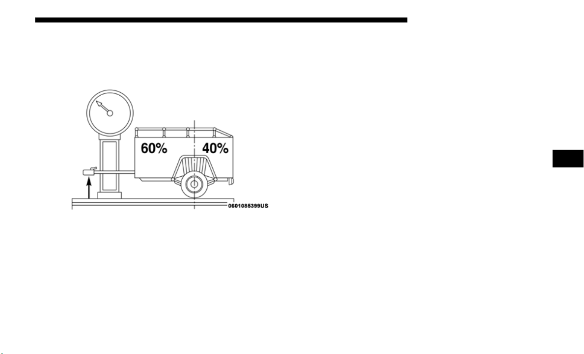
STARTING AND OPERATING 393
Trailer And Tongue Weight
Never exceed the maximum tongue weight stamped on your
bumper or trailer hitch.
Consider the following items when computing the weight on
the rear
axle of the vehicle:
• The tongue weight of the trailer.
• The weigh
t of any other type of cargo or equipment put in
or on yo
ur vehicle.
• The weight of the driver and all passengers.
NOTE:
Rem
ember that everything put into or on the trailer adds to
t
he load
on your vehicle. Also, additional factory-installed
options or dealer-installed options must be considered as
part of the total load on your vehicle. Refer to the “Tire And
Loading Information” placard for the maximum combined
weight of occupants and cargo for your vehicle.
Towing Requirements — Tires
• P
roper tire inflation pressures are essential to the safe and
satisfa
ctory operation of your vehicle. Refer to “Tires –
General Information” in “Servicing And Maintenance” for
proper tire inflation procedures.
• Check the trailer tires for proper tire inflation pressures
before
trailer usage.
• Check for signs of tire wear or visible tire damage before
towing a
trailer. Refer to “Tires – General Information” in
“Servicing And Maintenance” for proper inspection proce
-
dure.
• W
hen replacing tires, refer to “Tires – General Informa-
tion” i
n “Servicing And Maintenance” for proper tire
replacem
ent procedures. Replacing tires with a higher
load carrying capacity will not increase the vehicle's
GVWR and GAWR limits.
5

394 STARTING AND OPERATING
Towing Requirements — Trailer Brakes
• Do not interconnect the hydraulic brake system or vacuum
syste
m of your vehicle with that of the trailer. This could
cause inadequate braking and possible personal injury.
• An electronically actuated trailer brake controller is
requir
ed when towing a trailer with electronically actu-
ated brakes. When towing a trailer equipped with a
h
ydrauli
c surge actuated brake system, an electronic brake
controller is not required.
• Trailer brakes are recommended for trailers over 1,000 lbs
(453 k
g) and required for trailers in excess of 2,000 lbs (907 kg).
Towing Requirements — Trailer Lights And Wiring
Whenever you pull a trailer, regardless of the trailer size,
stopligh
ts and turn signals on the trailer are required for
motoring safety.
The Trailer Tow Package may include a four- and seven-pin
wiring ha
rness. Use a factory approved trailer harness and
connector.
NOTE:
Do not cut or splice wiring into the vehicle’s wiring harness.
The electrical connections are all complete to the vehicle but
you must
mate the harness to a trailer connector. Refer to the
following illustrations.
WARNING!
• Do not connect trailer brakes to your vehicle's
hydraul
ic brake lines. It can overload your brake
system and cause it to fail. You might not have brakes
when you need them and could have an accident.
• Towing any trailer will increase your stopping
distan
ce. When towing, you should allow for addi-
tional space between your vehicle and the vehicle in
f
ront of
you. Failure to do so could result in an accident.
CAUTION!
If the trailer weighs more than 1,000 lbs (453 kg) loaded,
it shoul
d have its own brakes and they should be of
adequate capacity. Failure to do this could lead to
accelerated brake lining wear, higher brake pedal effort,
and longer stopping distances.
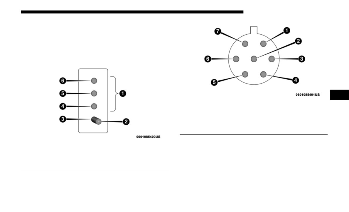
STARTING AND OPERATING 395
NOTE:
• Disconnect trailer wiring connector from the vehicle
before
launching a boat (or any other device plugged into
vehicle’s electrical connect) into water.
• Be sure to reconnect once clear from water area.
Four-Pin
Connector
Seven-Pin Connector
Towing Tips
Before setting out on a trip, practice turning, stopping and
backing the trailer in an area away from heavy traffic.
If using a manual transmission vehicle for trailer towing, all
starts m
ust be in first gear to avoid excessive clutch slippage.
1 — Female Pins 4 — Park
2 — Male Pin 5 — Left Stop/Turn
3 — Ground 6 — Right Stop/Turn
1 — Battery 5 — Ground
2 — Backup Lamps 6 — Left Stop/Turn
3 — Right Stop/Turn 7 — Running Lamps
4 — Electric Brakes
5

396 STARTING AND OPERATING
Automatic Transmission — If Equipped
Select the DRIVE range when towing. The transmission
control
s include a drive strategy to avoid frequent shifting
when towing. However, if frequent shifting does occur while
in DRIVE, you can use the AutoStick shift control to manu
-
ally select a lower gear.
NOTE:
Using a lower gear while operating the vehicle under heavy
l
oading
conditions, will improve performance and extend
transmission life by reducing excessive shifting and heat
buildup. This action will also provide better engine braking.
AutoStick — If Equipp
ed
• When using the AutoStick shift control, select the highest
gear th
at allows for adequate performance and avoids
frequent downshifts. For example, choose “5” if the
desired speed can be maintained. Choose “4” or “3” if
needed to maintain the desired speed.
• To prevent excess heat generation, avoid continuous
drivin
g at high RPM. Reduce vehicle speed as necessary to
avoid extended driving at high RPM. Return to a higher
gear or vehicle speed when grade and road conditions
allow.
Electronic Speed Control — If Equipped
• D
o not use in hilly terrain or with heavy loads.
• When u
sing the speed control, if you experience speed
drops
greater than 10 mph (16 km/h), disengage until you
can get
back to cruising speed.
• Use speed control in flat terrain and with light loads to
maximi
ze fuel efficiency.
Cooling System
To reduce potential for engine and transmission over-
heating, take the following actions:
City Driving
When stopped for short periods of time, shift the transmis-
sion into NEUTRAL and increase engine idle speed.
Highway Driving
Reduce speed.
Air Conditioning
Turn off temporarily.

STARTING AND OPERATING 397
RECREATIONAL TOWING (BEHIND MOTORHOME, ETC.)
Towing This Vehicle Behind Another Vehicle
Towing Condition Wheels OFF the Ground Four-Wheel Drive Models
Flat Tow NONE
See Instructions
• A
utomatic transmission in PARK.
• Manual
transmission in gear (NOT in
NEUTRA
L [N]).
• Transfer case in NEUTRAL (N).
• Tow in
forward direction.
Dolly T
ow
Front NOT ALLOWED
Rear NOT ALLOWED
On Trailer ALL OK
NOTE:
When towing your vehicle, always follow applicable state and provincial laws. Contact state and provincial Highway Safety
o
ffices
for additional details.
5

398 STARTING AND OPERATING
(Continued)
Recreational Towing — Four-Wheel Drive Models
NOTE:
The transfer case must be shifted into NEUTRAL (N), auto-
matic transmission must be in PARK, and manual transmis-
sion must be in gear (NOT in NEUTRAL) for recreational
t
owing.
Shif
ting Into NEUTRAL (N)
Use the following procedure to prepare your vehicle for
recreat
ional towing.
CAUTION!
• D
O NOT dolly tow any 4WD vehicle. Towing with
only one
set of wheels on the ground (front or rear) will
cause severe transmission and/or transfer case damage.
Tow with all four wheels either ON the ground, or OFF
the ground (using a vehicle trailer).
• Tow only in the forward direction. Towing this vehicle
backwa
rds can cause severe damage to the transfer case.
• Automatic transmissions must be placed in PARK for
recrea
tional towing.
• Manual transmissions must be placed in gear (not in
Neutra
l) for recreational towing.
• Before recreational towing, perform the procedure
outline
d under “Shifting Into NEUTRAL (N)” to be
certain that the transfer case is fully in NEUTRAL (N).
Otherwise, internal damage will result.
• Towing this vehicle in violation of the above require-
ments can cause severe transmission and/or transfer
case da
mage. Damage from improper towing is not
covered under the New Vehicle Limited Warranty.
• Do not use a bumper-mounted clamp-on tow bar on
your vehi
cle. The bumper face bar will be damaged.
WARNING!
You or others could be injured or killed if you leave the
vehicle
unattended with the transfer case in the
NEUTRAL (N) position without first fully engaging the
parking brake. The transfer case NEUTRAL (N) position
disengages both the front and rear driveshafts from the
powertrain, and will allow the vehicle to roll, even if the
automatic transmission is in PARK (or manual
transmission is in gear). The parking brake should
always be applied when the driver is not in the vehicle.
CAUTION! (Continued)

STARTING AND OPERATING 399
1. Bring the vehicle to a complete stop on level ground.
2. Press and hold the brake pedal.
3. Shif
t the automatic transmission into NEUTRAL or
depres
s the clutch pedal on a manual transmission.
4. Turn the engine OFF.
5. Shif
t the transfer case lever into NEUTRAL (N).
6. Star
t the engine.
7. Shif
t the transmission into REVERSE.
8. Rele
ase the brake pedal (and clutch pedal on manual
transm
issions) for five seconds and ensure that there is no
vehicle movement.
9. Repeat steps seven and eight with automatic transmis-
sion i
n DRIVE or manual transmission in first gear.
10. T
urn the engine OFF.
11. Firm
ly apply the parking brake.
12. Shi
ft the transmission into PARK or place manual trans-
missio
n in gear (NOT in NEUTRAL).
13. A
ttach the vehicle to the tow vehicle using a suitable tow
bar.
14.
Release the parking brake.
Shifting
Out of NEUTRAL (N)
Use the following procedure to prepare your vehicle for
normal
usage.
1. Bring the vehicle to a complete stop, leaving it connected
to the
tow vehicle.
2. Firmly apply the parking brake.
3. Star
t the engine.
CAUTIO
N!
It is necessary to follow these steps to be certain that the
transfe
r case is fully in NEUTRAL (N) before
recreational towing to prevent damage to internal parts.
CAUTION!
Damage to the transmission may occur if the
transmi
ssion is shifted into PARK with the transfer case
in NEUTRAL (N) and the engine running. With the
transfer case in NEUTRAL (N) ensure that the engine is
OFF before shifting the transmission into PARK.
5

400 STARTING AND OPERATING
4. Press and hold the brake pedal.
5. Shift the transmission into NEUTRAL.
6. Turn
the engine OFF.
7. Shif
t the transfer case lever to the desired position.
NOTE:
Wh
en shifting the transfer case out of NEUTRAL (N), the
e
ngine s
hould remain OFF to avoid gear clash.
8. Shift the automatic transmission into PARK, or place
manual
transmission in NEUTRAL.
9. Release the brake pedal.
10. Dis
connect vehicle from the tow vehicle.
11. Sta
rt the engine.
12. Pre
ss and hold the brake pedal.
13. Rel
ease the parking brake.
14. Shi
ft the transmission into gear, release the brake pedal
(and c
lutch pedal on manual transmissions), and check
that the vehicle operates normally.
DRIVING TIPS
On-Road Driving Tips
Utility vehicles have higher ground clearance and a
narrower track to make them capable of performing in a
wide variety of off-road applications. Specific design charac
-
teristics give them a higher center of gravity than conven-
tional passenger cars.
An advantage of the higher ground clearance is a better view
o
f the
road, allowing you to anticipate problems. They are
not designed for cornering at the same speeds as conven
-
tional passenger cars any more than low-slung sports cars
are des
igned to perform satisfactorily in off-road conditions.
Avoid sharp turns or abrupt maneuvers. As with other vehi
-
cles of this type, failure to operate this vehicle correctly may
result
in loss of control or vehicle rollover.
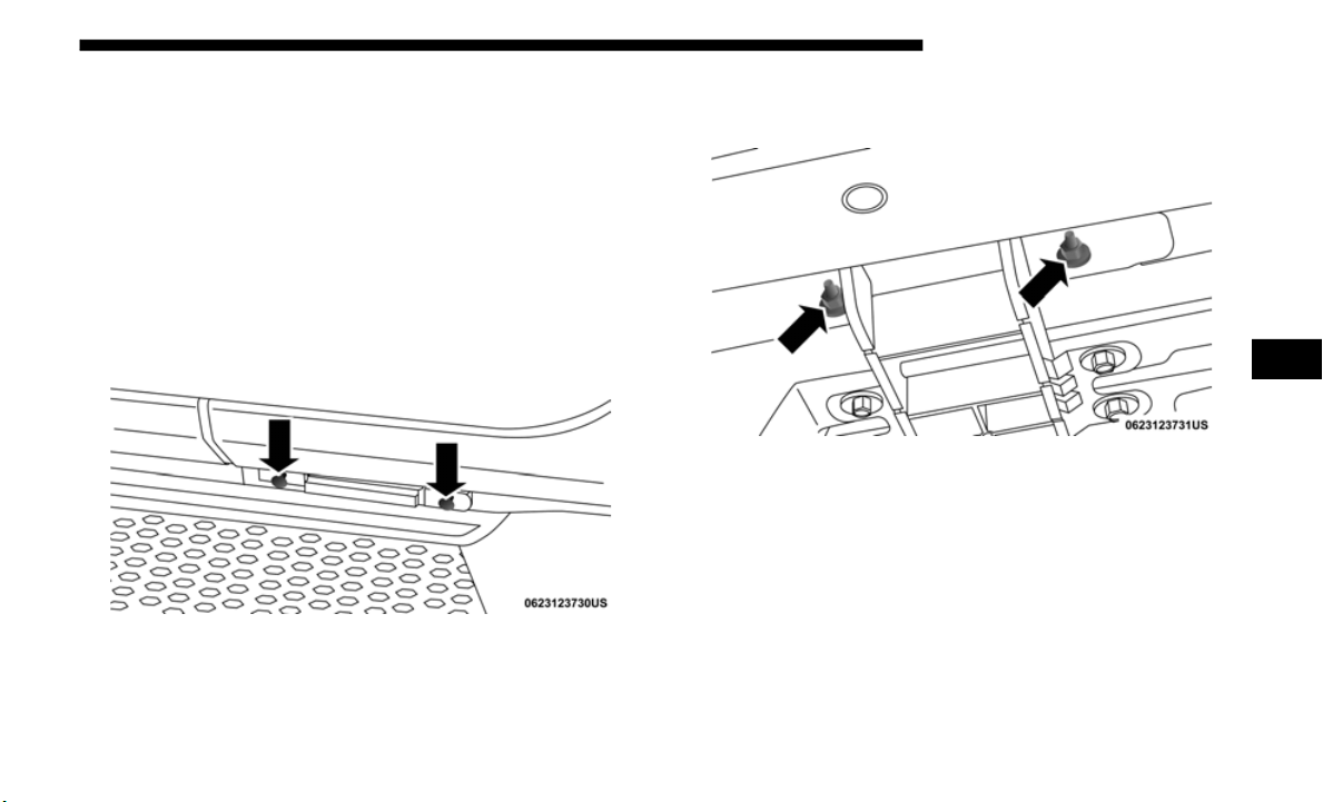
STARTING AND OPERATING 401
Off-Road Driving Tips
Side Step Removal — If Equipped
NOTE:
Prior to off-road usage, the side steps should be removed to
prevent
damage if so equipped.
1. T
here are two studs on the bodyside of each connecting
b
racket.
B
odyside Studs
2. R
emove both nuts from the underside of the vehicle for
each br
acket.
Underside Nuts
3. Remove the side step assembly.
5
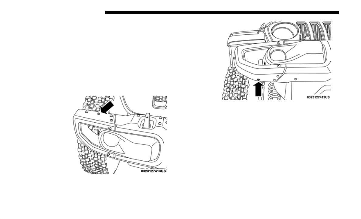
402 STARTING AND OPERATING
Bumper End Cap Removal
The end caps on your vehicle’s front bumper can be removed
by followi
ng the steps below:
NOTE:
Bumper end caps are removable on steel bumper only.
1. L
oosen the two bolts that retain the GAWR bracket (Bolts
#1 and #2
) to the end cap using a T45 torx bit screw
driver. Do not remove the bolts.
Bolt #1
Bolt #2
2. Remove the remaining 8 bolts. The end cap can now be
expande
d open.
3. Gently remove the end cap from the vehicle and store it
where it
will not get damaged.
4. Repeat this procedure on the other side.

STARTING AND OPERATING 403
The Basics Of Off-Road Driving
You will encounter many types of terrain driving off-road. You
should
be familiar with the terrain and area before proceeding.
There are many types of surface conditions: hard-packed dirt,
gravel, rocks, grass, sand, mud, snow and ice. Every surface
has a different effect on your vehicle's steering, handling and
traction. Controlling your vehicle is one of the keys to
successful off-road driving, so always keep a firm grip on the
steering wheel and maintain a good driving posture. Avoid
sudden accelerations, turns or braking. In most cases, there are
no road signs, posted speed limits or signal lights. Therefore,
you will need to use your own good judgment on what is safe
and what is not. When on a trail, you should always be looking
ahead for surface obstacles and changes in terrain. The key is
to plan your future driving route while remembering what
you are currently driving over.
NOTE:
It is recommended that the Start/Stop System be disabled
during o
ff-road use.
When To Use 4L (Low) Range
When off-road driving, shift into 4L (Low) for additional
tractio
n and control on slippery or difficult terrain,
ascending or descending steep hills, and to increase low
speed pulling power. This range should be limited to
extreme situations such as deep snow, mud, steep inclines,
or sand where additional low speed pulling power is
needed. Vehicle speeds in excess of 25
mph (40 km/h)
should
be avoided when in 4L (Low) range.
WARNING!
Always wear your seat belt and firmly tie down cargo.
Unsecur
ed cargo can become projectiles in an off-road
situation.
CAUTION!
Never park your vehicle over dry grass or other
combusti
ble materials. The heat from your vehicle
exhaust system could cause a fire.
CAUTION!
Do not use 4L (Low) range when operating the vehicle on
dry pavem
ent. Driveline hardware damage can result.
5

404 STARTING AND OPERATING
Simultaneous Brake And Throttle Operation
Many off-road driving conditions require the simultaneous
use of
the brake and throttle (two-footed driving). When
climbing rocks, logs, or other stepped objects, using light
brake pressure with light throttle will keep the vehicle from
jerking or lurching. This technique is also used when you
need to stop and restart a vehicle on a steep incline.
Driving In Snow, Mud And Sand
Snow
In heavy snow or for additional control and traction at
s
lower s
peeds, shift the transmission into a low gear and the
transfer case into 4L (Low) if necessary. Do not shift to a
lower gear than necessary to maintain headway.
Over-revving the engine can spin the wheels and traction
will be lost. If you start to slow to a stop, try turning your
steering wheel no more than a 1/4 turn quickly back and
forth, while still applying throttle. This will allow the tires to
get a fresh "bite" and help maintain your momentum.
Mud
Deep mud creates a great deal of suction around the tires and
is very
difficult to get through. You should use DRIVE, with
the transfer case in the 4L (Low) position to maintain your
momentum. If you start to slow to a stop, try turning your
steering wheel no more than a 1/4 turn quickly back and
forth for additional traction. Mud holes pose an increased
threat of vehicle damage and getting stuck. They are
normally full of debris from previous vehicles getting stuck.
As a good practice before entering any mud hole, get out and
determine how deep it is, if there are any hidden obstacles
and if the vehicle can be safely recovered if stuck.
Sand
Soft sand is very difficult to travel through with full tire pres-
sure. When crossing soft, sandy spots in a trail, maintain
your veh
icle's momentum and do not stop. The key to
driving in soft sand is using the appropriate tire pressure,
accelerating slowly, avoiding abrupt maneuvers and main
-
taining the vehicle's momentum. If you are going to be
d
riving
on large soft sandy areas or dunes, reduce your tire
pressure to a minimum of 15 psi (103 kPa) to allow for a
greater tire surface area. Reduced tire pressure will drasti
-
cally improve your traction and handling while driving on
t
he sof
t sand, but you must return the tires to normal air
CAUTION!
On icy or slippery roads, do not downshift at high
engine R
PM or vehicle speeds, because engine braking
may cause skidding and loss of control.

STARTING AND OPERATING 405
pressure before driving on pavement or other hard surfaces.
Be sure you have a way to reinflate the tires prior to reducing
the pressure.
Crossing Obstacles (Rocks And Other High Points)
While driving off-road, you will encounter many types of
terrain
. These varying types of terrain bring different types
of obstacles. Before proceeding, review the path ahead to
determine the correct approach and your ability to safely
recover the vehicle if something goes wrong. Keeping a firm
grip on the steering wheel, bring the vehicle to a complete
stop and then inch the vehicle forward until it makes contact
with the object. Apply the throttle lightly while holding a
light brake pressure and ease the vehicle up and over the
object.
Using A Spotter
There are many times where it is hard to see the obstacle or
determi
ne the correct path. Determining the correct path can
be extremely difficult when you are confronting many obsta
-
cles. In these cases have someone guide you over, through, or
around
the obstacle. Have the person stand a safe distance in
front of you where they can see the obstacle, watch your tires
and undercarriage, and guide you through.
Crossing Large Rocks
When approaching large rocks, choose a path which ensures
you driv
e over the largest of them with your tires. This will
lift your undercarriage over the obstacle. The tread of the tire
is tougher and thicker than the side wall and is designed to
take the abuse. Always look ahead and make every effort to
cross the large rocks with your tires.
CAUTION!
Reduced tire pressures may cause tire unseating and
total los
s of air pressure. To reduce the risk of tire
unseating, while at a reduced tire pressure, reduce your
speed and avoid sharp turns or abrupt maneuvers.
WARNING!
Crossing obstacles can cause abrupt steering system
loading w
hich could cause you to loose control of your
vehicle.
5

406 STARTING AND OPERATING
Crossing A Ravine, Gully, Ditch, Washout Or Rut
When crossing a ravine, gully, ditch, washout or a large rut,
the angl
ed approach is the key to maintaining your vehicle's
mobility. Approach these obstacles at a 45-degree angle and
let each tire go through the obstacle independently. You
need to use caution when crossing large obstacles with steep
sides. Do not attempt to cross any large obstacle with steep
sides at an angle great enough to put the vehicle at risk of a
rollover. If you get caught in a rut, dig a small trench to the
right or left at a 45-degree angle ahead of the front tires. Use
the removed dirt to fill the rut ahead of the turnout you just
created. You should now be able to drive out following the
trench you just created at a 45-degree angle.
Crossing Logs
To cross a log, approach it at a slight angle (approximately 10
to 15 d
egrees). This allows one front tire to be on top of the
log while the other just starts to climb the log. While climbing
the log, modulate your brake and accelerator to avoid spin
-
ning the log out from under your tires. Then ease the vehicle
o
ff the
log using your brakes.
Getting High-Centered
If you get hung up or high-centered on an object, get out of
the veh
icle and try to determine what the vehicle is hung up
on, where it is contacting the underbody and what is the best
direction to recover the vehicle. Depending on what you are
in contact with, jack the vehicle up and place a few rocks
under the tires so the weight is off of the high point when
you let the vehicle down. You can also try rocking the vehicle
or winching the vehicle off the object.
CAUTION!
• N
ever attempt to straddle a rock that is large enough to
strike
your axles or undercarriage.
• Never attempt to drive over a rock which is large
enough t
o contact the door sills.
WARNING!
There is an increased risk of rollover when crossing an
obstacle
, at any angle, with steep sides.
CAUTION!
Do not attempt to cross a log with a greater diameter than
the run
ning ground clearance or the vehicle will become
high-centered.
STARTING AND OPERATING 407
Hill Climbing
Hill climbing requires good judgment and a good under-
standing of your abilities and your vehicle's limitations. Hills
can cau
se serious problems. Some are just too steep to climb
and should not be attempted. You should always feel confi
-
dent with the vehicle and your abilities. You should always
climb h
ills straight up and down. Never attempt to climb a
hill on an angle.
Before Climbing A Steep Hill
As you approach a hill, consider its grade or steepness.
Determi
ne if it is too steep. Look to see what the traction is
on the hill side trail. Is the trail straight up and down? What
is on top and the other side? Are there ruts, rocks, branches
or other obstacles on the path? Can you safely recover the
vehicle if something goes wrong? If everything looks good
and you feel confident, shift the transmission into a lower
gear with 4L (Low) engaged, and proceed with caution,
maintaining your momentum as you climb the hill.
Driving Up Hill
Once you have determined your ability to proceed and have
shifted
into the appropriate gear, line your vehicle up for the
straightest possible run. Accelerate with an easy constant
throttle and apply more power as you start up the hill. Do
not race forward into a steep grade; the abrupt change of
grade could cause you to lose control. If the front end begins
to bounce, ease off the throttle slightly to bring all four tires
back on the ground. As you approach the crest of the hill,
ease off the throttle and slowly proceed over the top. If the
wheels start to slip as you approach the crest of a hill, ease off
the accelerator and maintain headway by turning the
steering wheel no more than a 1/4 turn quickly back and
forth. This will provide a fresh "bite" into the surface and will
usually provide enough traction to complete the climb. If
you do not make it to the top, place the vehicle in REVERSE
and back straight down the grade using engine resistance
along with the vehicle brakes.
CAUTION!
Winching or rocking the vehicle off hard objects
increases the risk of underbody damage.
WARNING!
Never attempt to climb a hill at an angle or turn around
on a ste
ep grade. Driving across an incline increases the
risk of a rollover, which may result in severe injury.
5

408 STARTING AND OPERATING
Driving Downhill
Before driving down a steep hill, you need to determine if it
is too
steep for a safe descent. What is the surface traction? Is
the grade too steep to maintain a slow, controlled descent?
Are there obstacles? Is it a straight descent? Is there plenty of
distance at the base of the hill to regain control if the vehicle
descends to fast? If you feel confident in your ability to
proceed, then make sure you are in 4L (Low) and proceed
with caution. Allow engine braking to control the descent
and apply your brakes, if necessary, but do not allow the
tires to lock.
Driving Across An Incline
If at all possible, avoid driving across an incline. If it is neces-
sary, know your vehicle's abilities. Driving across an incline
places
more weight on the downhill wheels, which increases
the possibilities of a downhill slide or rollover. Make sure the
surface has good traction with firm and stable soils. If
possible, transverse the incline at an angle heading slightly
up or down.
If You Stall Or Begin To Lose Headway
If you stall or begin to lose headway while climbing a steep
hill, a
llow your vehicle to come to a stop and immediately
apply the brake. Restart the engine and shift into REVERSE.
Back slowly down the hill allowing engine braking to control
the descent and apply your brakes, if necessary, but do not
allow the tires to lock.
WARNING!
Do not descend a steep grade in NEUTRAL. Use vehicle
brakes
in conjunction with engine braking. Descending
a grade too fast could cause you to lose control and be
seriously injured or killed.
WARNING!
Driving across an incline increases the risk of a rollover,
which m
ay result in severe injury.
WARNING!
If the engine stalls or you lose headway or cannot make
it to th
e top of a steep hill or grade, never attempt to turn
around. To do so may result in tipping and rolling the
vehicle, which may result in severe injury. Always back
carefully straight down a hill in REVERSE. Never back
down a hill in NEUTRAL using only the vehicle brakes.
Never drive diagonally across a hill, always drive
straight up or down.

STARTING AND OPERATING 409
Driving Through Water
Extreme care should be taken crossing any type of water.
Water c
rossings should be avoided, if possible, and only be
attempted when necessary in a safe, responsible manner.
You should only drive through areas which are designated
and approved. You should tread lightly and avoid damage
to the environment. You should know your vehicle's abilities
and be able to recover it if something goes wrong. You
should never stop or shut a vehicle off when crossing deep
water unless you ingested water into the engine air intake. If
the engine stalls, do not attempt to restart it. Determine if it
has ingested water first. The key to any crossing is low and
slow. Shift into first gear (manual transmission), or DRIVE
(automatic transmission), with the transfer case in the 4L
(Low) position and proceed very slowly with a constant slow
speed {3 to 5
mph (5 to 8 km/h) maximum} and light throttle.
Keep th
e vehicle moving; do not try to accelerate through the
crossing. After crossing any water higher than the bottom of
the axle differentials, you should inspect all of the vehicle
fluids for signs of water ingestion.
Before You Cross Any Type Of Water
As you approach any type of water, you need to determine if
you can
cross it safely and responsibly. If necessary, get out
and walk through the water or probe it with a stick. You need
to be sure of its depth, approach angle, current and bottom
condition. Be careful of murky or muddy waters; check for
hidden obstacles. Make sure you will not be intruding on any
wildlife, and you can recover the vehicle if necessary. The key
to a safe crossing is the water depth, current and bottom condi
-
tions. On soft bottoms, the vehicle will sink in, effectively
increas
ing the water level on the vehicle. Be sure to consider
this when determining the depth and the ability to safely cross.
CAUTION!
• Water ingestion into the axles, transmission, transfer
case,
engine or vehicle interior can occur if you drive
too fast or through too deep of water. Water can cause
permanent damage to engine, driveline or other vehicle
components, and your brakes will be less effective once
wet and/or muddy.
• When driving through water, do not exceed 5 mph
(8 k
m/h). Always check water depth before entering as
a preca
ution, and check all fluids afterward. Driving
through water may cause damage that may not be
covered by the New Vehicle Limited Warranty.
5

410 STARTING AND OPERATING
Crossing Puddles, Pools, Flooded Areas Or Other Standing
Water
Puddles, pools, flooded or other standing water areas
normall
y contain murky or muddy waters. These water
types normally contain hidden obstacles and make it diffi
-
cult to determine an accurate water depth, approach angle,
and bot
tom condition. Murky or muddy water holes are
where you want to hook up tow straps prior to entering. This
makes for a faster, cleaner and easier vehicle recovery. If you
are able to determine you can safely cross, than proceed
using the low and slow method.
Crossing Ditches, Streams, Shallow Rivers Or Other
Flowing Wa
ter
Flowing water can be extremely dangerous. Never attempt
to cros
s a fast running stream or river even in shallow water.
Fast moving water can easily push your vehicle down
-
stream, sweeping it out of control. Even in very shallow
water, a
high current can still wash the dirt out from around
your tires putting you and your vehicle in jeopardy. There is
still a high risk of personal injury and vehicle damage with
slower water currents in depths greater than the vehicle's
running ground clearance. You should never attempt to
cross flowing water which is deeper than the vehicle's
running ground clearance. Even the slowest current can
push the heaviest vehicle downstream and out of control if
the water is deep enough to push on the large surface area of
the vehicle's body. Before you proceed, determine the speed
of the current, the water's depth, approach angle, bottom
condition and if there are any obstacles. Then cross at an
angle heading slightly upstream using the low and slow
technique.
CAUTION!
Muddy waters can reduce the cooling system
e
ffecti
veness by depositing debris onto the radiator.
WARNING!
Never drive through fast moving deep water. It can push
your vehic
le downstream, sweeping it out of control.
This could put you and your passengers at risk of injury
or drowning.

STARTING AND OPERATING 411
After Driving Off-Road
Off-road operation puts more stress on your vehicle than
does mo
st on-road driving. After going off-road, it is always
a good idea to check for damage. That way you can get any
problems taken care of right away and have your vehicle
ready when you need it.
• Completely inspect the underbody of your vehicle. Check
tires,
body structure, steering, suspension, and exhaust
system for damage.
• Inspect the radiator for mud and debris and clean as
requir
ed.
• Check threaded fasteners for looseness, particularly on the
chassi
s, drivetrain components, steering, and suspension.
Retighten them, if required, and torque to the values spec
-
ified in the Service Manual.
• C
heck for accumulations of plants or brush. These things
could
be a fire hazard. They might hide damage to fuel
lines, brake hoses, axle pinion seals, and propeller shafts.
• After extended operation in mud, sand, water, or similar
dirty c
onditions, have the radiator, fan, brake rotors,
wheels, brake linings, and axle yokes inspected and
cleaned as soon as possible.
NOTE:
Inspect the clutch vent holes in the manual transmission bell
h
ousing
for mud and debris and clean as required.
• If you experience unusual vibration after driving in mud,
slush
or similar conditions, check the wheels for impacted
material. Impacted material can cause a wheel imbalance
and freeing the wheels of it will correct the situation.
WARNING!
Abrasive material in any part of the brakes may cause
excessi
ve wear or unpredictable braking. You might not
have full braking power when you need it to prevent a
collision. If you have been operating your vehicle in
dirty conditions, get your brakes checked and cleaned as
necessary.
5
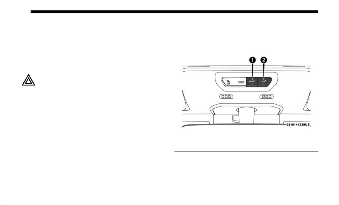
412
IN CASE OF EMERGENCY
HAZARD WARNING FLASHERS
The Hazard Warning flasher switch is located on the instru-
ment panel below the climate controls.
Push the switch to turn on the Hazard Warning
flasher. When the switch is activated, all directional
t
urn sign
als will flash on and off to warn oncoming
traffic of an emergency. Push the switch a second time to
turn off the Hazard Warning flashers.
This is an emergency warning system and it should not be
used when
the vehicle is in motion. Use it when your vehicle
is disabled and it is creating a safety hazard for other motor
-
ists.
When you must leave the vehicle to seek assistance, the
Hazard W
arning flashers will continue to operate even
though the ignition is placed in the OFF position.
NOTE:
With extended use the Hazard Warning flashers may wear
down your
battery.
ASSIST AND SOS SYSTEM — IF EQUIPPED
Assist And SOS Buttons
If equipped, the overhead console contains an ASSIST and an
SOS butt
on.
1 — Assist Button
2 — SOS Button

IN CASE OF EMERGENCY 413
NOTE:
• Your vehicle may be transmitting data as authorized by
the su
bscriber.
• The SOS and ASSIST buttons will only function if you are
connec
ted to an operable LTE (voice/data) or 4G (data)
network. Other Uconnect services will only be operable if
your SiriusXM Guardian service is active and you are
connected to an operable LTE (voice/data) or 4G (data)
network.
ASSIST Call
The ASSIST Button is used to automatically connect you to
any one
of the following support centers:
• Roadside Assistance – If you get a flat tire, or need a tow,
just p
ush the ASSIST button and you’ll be connected to
someone who can help. Roadside Assistance will know
what vehicle you’re driving and its location. Additional
fees may apply for roadside assistance.
• SiriusXM Guardian Customer Care – In-vehicle support
for Si
riusXM Guardian.
• Vehicle Customer Care – Total support for all other vehicle
issues
.
SOS Call
1. P
ush the SOS Call button on the overhead console.
NOTE:
In
case the SOS Call button is pushed in error, there will be a
ten sec
ond delay before the SOS Call system initiates a call to
a SOS operator. To cancel the SOS Call connection, push the
SOS call button on the overhead console or press the cancel
-
lation button on the Device Screen. Termination of the SOS
C
all wil
l turn off the green LED light on the overhead
console.
WARNING!
ALWAYS obey traffic laws and pay attention to the road.
ALWAYS
drive safely with your hands on the steering
wheel. You have full responsibility and assume all risks
related to the use of the features and applications in this
vehicle. Only use the features and applications when it is
safe to do so. Failure to do so may result in an accident
involving serious injury or death.
6

414 IN CASE OF EMERGENCY
(Continued)
2. The LED light located between the ASSIST and SOS
buttons on the overhead console will turn green once a
connection to a SOS operator has been made.
3. Once a connection between the vehicle and a SOS oper-
ator i
s made, the SOS Call system may transmit the
followin
g important vehicle information to a SOS oper-
ator:
• I
ndication that the occupant placed a SOS Call.
• The v
ehicle brand.
• The l
ast known GPS coordinates of the vehicle.
4. You
should be able to speak with the SOS operator
through
the vehicle audio system to determine if addi-
tional help is needed.
NOTE:
• Y
our vehicle may be transmitting data as authorized by
the su
bscriber.
• Once a connection is made between the vehicle’s SOS Call
system
and the SOS operator, the SOS operator may be
able to open a voice connection with the vehicle to deter
-
mine if additional help is needed. Once the SOS operator
opens a
voice connection with the vehicle’s SOS Call
system, the operator should be able to speak with you or
other vehicle occupants and hear sounds occurring in the
vehicle. The vehicle’s SOS Call system will attempt to
remain connected with the SOS operator until the SOS
operator terminates the connection.
5. The SOS operator may attempt to contact appropriate
emergen
cy responders and provide them with important
vehicle information and GPS coordinates.
WARNING!
ALWAYS obey traffic laws and pay attention to the road.
ALWAYS
drive safely with your hands on the steering
wheel. You have full responsibility and assume all risks
related to the use of the features and applications in this
vehicle. Only use the features and applications when it is
safe to do so. Failure to do so may result in an accident
involving serious injury or death.
WARNING!
• If anyone in the vehicle could be in danger (e.g., fire or
smoke i
s visible, dangerous road conditions or loca-
tion), do not wait for voice contact from an Emergency
S
ervices
Agent. All occupants should exit the vehicle
immediately and move to a safe location.

IN CASE OF EMERGENCY 415
(Continued)
SOS Call System Limitations
Vehicles sold in Mexico DO NOT h
ave SOS Call system
capabilities.
SOS or other emergency line operators in Mexico may not
a
n
swer o
r respond to SOS system calls.
If the SOS Call system detects a malfunction, any of the
followin
g may occur at the time the malfunction is detected,
and at the beginning of each ignition cycle:
• The light located between the ASSIST and SOS buttons
will co
ntinuously be illuminated red.
• The Device Screen will display the following message
“Vehic
le device requires service. Please contact your
dealer.”
• An In-Vehicle Audio message will state “Vehicle device
requir
es service. Please contact your dealer.”
• Never place anything on or near the vehicle’s operable
network
and GPS antennas. You could prevent oper-
able network and GPS signal reception, which can
p
revent
your vehicle from placing an emergency call.
An operable network and GPS signal reception is
required for the SOS Call system to function properly.
• The SOS Call system is embedded into the vehicle’s elec-
trical
system. Do not add aftermarket electrical equip-
ment to the vehicle’s electrical system. This may prevent
y
our ve
hicle from sending a signal to initiate an emer-
gency call. To avoid interference that can cause the SOS
C
all sy
stem to fail, never add aftermarket equipment
(e.g., two-way mobile radio, CB radio, data recorder, etc.)
to your vehicle’s electrical system or modify the antennas
on your vehicle. IF YOUR VEHICLE LOSES BATTERY
POWER FOR ANY REASON (INCLUDING DURING
OR AFTER AN ACCIDENT), THE UCONNECT
FEATURES, APPS AND SERVICES, AMONG OTHERS,
WILL NOT OPERATE.
• Modifications to any part of the SOS Call system could
cause
the air bag system to fail when you need it. You
could be injured if the air bag system is not there to
help protect you.
WARNING! (Continued)
WARNING!
• Ignoring the Rearview Mirror light could mean you
will n
ot have SOS Call services. If the Rearview Mirror
light is illuminated, have your authorized dealer
service the SOS Call system immediately.
6

416 IN CASE OF EMERGENCY
Even if the SOS Call system is fully functional, factors
beyond FCA US LLC’s control may prevent or stop the SOS
Call system operation. These include, but are not limited to,
the following factors:
• Delayed accessories mode is active.
• The ign
ition is in the OFF position.
• The ve
hicle’s electrical systems are not intact.
• The SO
S Call system software and/or hardware are
damaged
during a crash.
• The vehicle battery loses power or becomes disconnected
during
a vehicle crash.
• LTE (voice/data) or 4G (data) network and/or Global
Positi
oning Satellite signals are unavailable or obstructed.
• Equipment malfunction at the SOS operator facility.
• Opera
tor error by the SOS operator.
• LTE (v
oice/data) or 4G (data) network congestion.
• Weathe
r.
• Buildi
ngs, structures, geographic terrain, or tunnels.
NOTE:
• Y
our vehicle may be transmitting data as authorized by
the su
bscriber.
• Never place anything on or near the vehicle’s LTE (voice/
data)
or 4G (data) and GPS antennas. You could prevent
LTE (voice/data) or 4G (data) and GPS signal reception,
which can prevent your vehicle from placing an emer
-
gency call. An operable LTE (voice/data) or 4G (data)
n
etwork c
onnection and a GPS signal is required for the
SOS Call system to function properly.
• The Occupant Restraint Control module turns on the
air ba
g Warning Light on the instrument panel if a
malfunction in any part of the system is detected. If the
Air Bag Warning Light is illuminated, have your autho
-
rized dealer service the Occupant Restraint Control
s
ystem i
mmediately.
WARNING! (Continued)
WARNING!
ALWAYS obey traffic laws and pay attention to the road.
ALWAYS
drive safely with your hands on the steering
wheel. You have full responsibility and assume all risks
related to the use of the features and applications in this
vehicle. Only use the features and applications when it is
safe to do so. Failure to do so may result in an accident
involving serious injury or death.

IN CASE OF EMERGENCY 417
General Information
This device complies with Part 15 of the FCC Rules. Opera-
tion is subject to the following two conditions: (1) This device
may not
cause harmful interference, and (2) this device must
accept any interference received, including interference that
may cause undesired operation.
NOTE:
Changes or modifications not expressly approved by the
party re
sponsible for compliance could void the user's
authority to operate the equipment.
BULB REPLACEMENT
Replacement Bulbs
CAUTION!
To avoid damage to the mirror during cleaning, never
spray an
y cleaning solution directly onto the mirror.
Apply the solution onto a clean cloth and wipe the
mirror clean.
Interior Bulbs
Bulb Number
Automatic Transmission Indicator Lamp 658
Heater Control Lamps (2) 194
Rocker Switch Indicator Lamp (Rear Window Defogger, and
R
ear Wa
sh/Wipe)
**
Soundbar Dome Lamp 912
** Bulbs only available from an authorized dealer.
6

418 IN CASE OF EMERGENCY
Exterior Bulbs
Bulb Number
Headlamps (2) H13
Premium Head Lamps LED – (Serviced At Authorized Dealer)
Sport Front Park/Turn Signal Lamps (2) 7442NALL
Premium Front Park/Turn Signal Lamps (2) LED – (Serviced At Authorized Dealer)
Base (Sahara/Rubicon) Turn Lamp 7440NA
Base (Sahara/Rubicon) Park DRL Lamp 7443
Front Side Marker Lamps (2) LED – (Serviced At Authorized Dealer)
Base Fog Lamps PSX24W
Premium Fog Lamps LED – (Serviced At Authorized Dealer)
Rear Premium LED Tail Lamps LED – (Serviced At Authorized Dealer)
Rear Base Tail Lamp Stop/Tail/Turn Bulb 3157
Rear Base Tail Lamp Backup Bulb 7440
Rear Base Tail Lamp Side Marker LED – (Serviced At Authorized Dealer)
Center High-Mounted Stop Lamp LED – (Serviced At Authorized Dealer)
License Lamp LED – (Serviced At Authorized Dealer)
NOTE:
Numbers refer to commercial bulb types that can be purchased from an authorized dealer. If a bulb needs to be replaced,
v
isit a
n authorized dealer or refer to the applicable Service Manual.

IN CASE OF EMERGENCY 419
Bulb Replacement
NOTE:
Lens fogging can occur under certain atmospheric condi-
tions. This will usually clear as atmospheric conditions
c
hange t
o allow the condensation to change back into a
vapor. Turning the lamps on will usually accelerate the
clearing process.
Halogen Headlamps
1. Open hood and support using prop rod.
2. Remo
ve the front grille. Turn the retainers along the top
1/4 tur
n counterclockwise and remove.
3. Pull the bottom of the grille away starting at one side and
working t
oward the other.
4. Remove the three screws holding the headlamp to the
vehicl
e.
5. Remove lamp from the vehicle.
6. Remo
ve the lamp from the collar.
7. Gras
p the bulb and turn 1/4 turn counterclockwise.
8. Pull
the bulb from the housing.
9. Push
connector locking tab to the unlock position.
10. Rem
ove connector from bulb.
11. Pus
h connector onto new bulb base, and push the
connec
tor locking tab to the lock position.
12. Reinstall bulb housing. Rotate the bulb 1/4 turn clock-
wise.
CAU
TION!
Do not touch the new bulb with your fingers. Oil
c
ontamin
ation will severely shorten bulb life. If the bulb
comes in contact with any oily surface, clean the bulb
with rubbing alcohol.
6
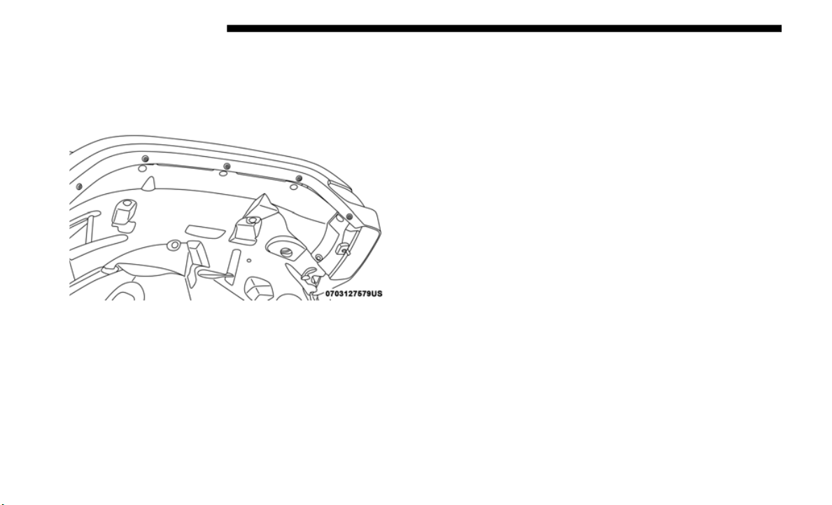
420 IN CASE OF EMERGENCY
Front Park/Turn Signal
1. Remove the front wheel liner fasteners to access bulb
sockets
.
Wheel Liner
2. Turn the socket assembly 1/4 turn counterclockwise and
remove
from housing. Pull the bulb straight from the
socket to replace.
LED Front Side Marker
1. Remove the front wheel liner fasteners to access side
maker s
crew and electrical connector.
2. R
emove fastening screw in the back of the front side
m
aker a
ssembly and disconnect electrical connector.
3. Remove and replace LED front side marker light
assemb
ly.
Halogen Front Fog Lamp
1. Reach under the vehicle to access the back of the front fog
lamp.
2.
Disconnect the wire harness connector from the front fog
lamp c
onnector receptacle.
3. Firmly grasp the bulb by the two latch features and
squeez
e them together to unlock the bulb from the back
of the front fog lamp housing.
4. Pull the bulb straight out from the keyed opening in the
housin
g and then connect the replacement bulb.
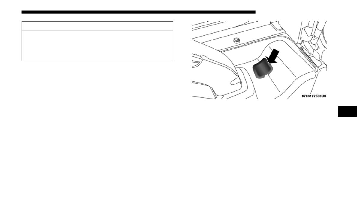
IN CASE OF EMERGENCY 421
LED Front Fog Lamp
If your vehicle is equipped with LED fog lamps they are
replace
d as an assembly.
Rear Tail, Stop, Turn Signal, And Backup Lamp
1. Remo
ve interior trim panel cap to access single retaining
screw f
or tail lamp assembly.
Trim Cap
2. Remove retaining screw and disconnect electrical
connec
tor, then remove tail lamp assembly from the
vehicle.
CAUTION!
Do not touch the new bulb with your fingers. Oil
contamin
ation will severely shorten bulb life. If the bulb
comes in contact with any oily surface, clean the bulb
with rubbing alcohol.
6
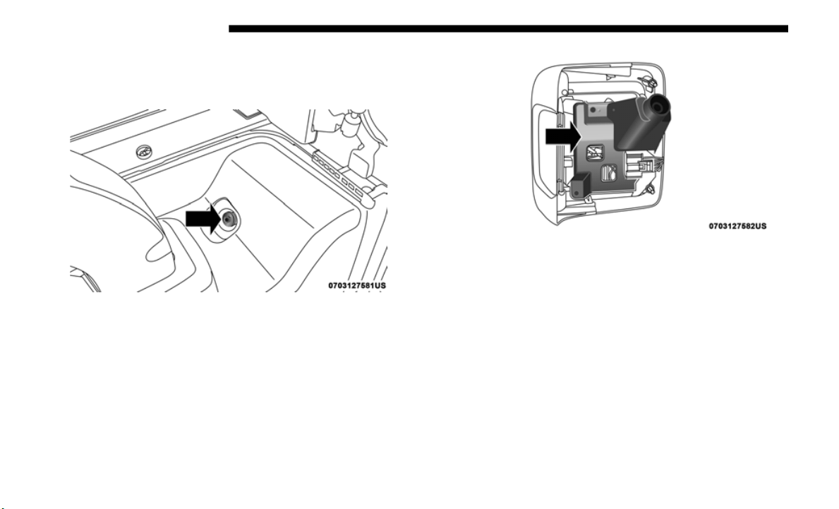
422 IN CASE OF EMERGENCY
NOTE:
If necessary, push in on the assembly tab located inboard
behind
the lamp housing.
Retaining Screw
3. Remove the three screws from assembly bracket to access
bulb s
ockets.
Assembly Bracket
4. Rotate the appropriate socket 1/4 turn counterclockwise,
then r
emove it from the housing.
5. Pull the bulb straight from the socket to replace.

IN CASE OF EMERGENCY 423
(Continued)
Center High-Mounted Stop Lamp (CHMSL)
The stop lamp is mounted on a bracket that extends upward
from th
e tailgate behind the spare tire. If service is needed,
obtain the LED Assembly from an authorized dealer.
1. Remove the spare tire.
2. Remo
ve the screws holding the tire carrier cover.
3. Remo
ve two screws from lamp assembly and disconnect
electr
ical connector.
License Plate Lamps
See an authorized dealer to replace these LED assemblies.
FUSES
General Information
The fuses protect electrical systems against excessive
current.
When a device does not work, you must check the fuse
e
l
ement
inside the blade fuse for a break/melt.
WARNING!
• When replacing a blown fuse, always use an appro-
priate
replacement fuse with the same amp rating as the
original
fuse. Never replace a fuse with another fuse of
higher amp rating. Never replace a blown fuse with
metal wires or any other material. Failure to use proper
fuses may result in serious personal injury, fire and/or
property damage.
• Before replacing a fuse, make sure that the ignition is
off and that all the other services are switched off and/
or disengaged.
• If the replaced fuse blows again, contact an authorized
dealer.
• If a general protection fuse for safety systems (air bag
system,
braking system), power unit systems (engine
system, gearbox system) or steering system blows,
contact an authorized dealer.
WARNING! (Continued)
6
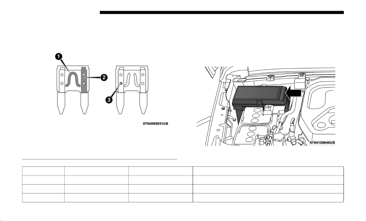
424 IN CASE OF EMERGENCY
Also, please be aware that when using power outlets for
extended periods of time with the engine off may result in
vehicle battery discharge.
Blade Fuses
Power Distribution Center (PDC)
The Power Distribution Center is located in the engine
compartment near the battery. This center contains cartridge
fuses, mini fuses, and relays. The PDC top cover is labelled
with each serviceable fuse/relay location, function, and size.
Power Distribution Center
1 — Fuse Element
2 — Blade Fuse with a good/functional fuse element.
3 — Blade fuse with a NOT functional / BAD fuse element (blown fuse).
Cavity Cartridge Fuse Micro Fuse Description
F01 – – Spare
F02 40 Amp Green – Starter
F03 – 5 Amp Tan Intelligent Battery Sensor (IBS)

IN CASE OF EMERGENCY 425
F04 – 20 Amp Yellow Fuel Pump MTR/FPCM
F05 – 5 Amp Tan Security Gateway
F06
–
– Spare
F07 – 15 Amp Blue Low Temp Radiator Cooling Pump (LTR) — If Equipped
F08 – 15 Amp Blue Trans Control Module TCM-8HP CYGNUS
F09 – – Spare
F10 – 15 Amp Blue
Key Ignition Node (KIN)/Radio Frequency Hub
(RF HUB)/Electric Steering Column Lock (ESCL)
F11 – 10 Amp Red UCI Port (USB & AUX)
F12 – 25 Amp Clear HIFI Amplifier
F13 – – Spare
F14 – – Spare
F15 – 15 Amp Blue
Instrument Panel Cluster (IPC)/Switch Bank-Heavy
D
uty Ele
ctrical Pkg (SWITCH BANK-HD ELEC)
F16 – – Spare
F17 – – Spare
F18 – 10 Amp Red Air Conditioning Clutch (AC CLUTCH)
F19 – – Spare
F20 30 Amp Pink – Central Body Controller (CBC) 1-INTERIOR LIGHTS
Cavity Cartridge Fuse Micro Fuse Description
6

426 IN CASE OF EMERGENCY
F21 – 20 Amp Yellow REAR WIPER
F22 – 10 Amp Red
Engine Control Module (ECM)/Powertrain Control
Module
(PCM)/Motor Generator Unit (MGU) WAKE
UP/Power Pack Unit (PPU) WAKE UP
F23 – 10 Amp Red
Powertrain Control Module (PCM)/Engine Control
M
odule
(ECM)
F24 – – Spare
F25 – 10 Amp Red Module Shift By Wire (MOD_SBW)
F26 40 Amp Green – Central Body Controller (CBC) 2-EXTERIOR LIGHTS #1
F27 30 Amp Pink – Front Wipers
F28 40 Amp Green – Central Body Controller (CBC) 3-POWER LOCKS
F29 40 Amp Green – Central Body Controller (CBC) 4-EXTERIOR LIGHTS #2
F30 – – Spare
F31 – 10 Amp Red DIAGNOSTIC PORT
F32 – 10 Amp Red
Heating Ventilation Air Conditioning Mod (HVAC
C
TRL MO
D)/Steering Column Lock (SCL)/Occupant
Classification Module (OCM)/Driver Presence Detection
Module (DPDM)
F33 – 10 Amp Red
ParkTronics System (PTS)/Infrared Camera Module
(
IRCM)/A
irbag Disable Lamps (AIRBAG DISABLE
LMPS)
Cavity Cartridge Fuse Micro Fuse Description

IN CASE OF EMERGENCY 427
F34 – 10 Amp Red
Electronic Stability Control (ESC)/Electric Hydraulic
Power St
eering (EHPS)/Smart Bar Control Module
(SBCM) WAKE UP
F35 30 Amp Pink – BRAKE VAC PMP — If Equipped
F36 30 Amp Pink – TRAILER TOW MOD — If Equipped
F37 30 Amp Pink – TRAILER TOW CONN 7W — If Equipped
F38 20 Amp Blue – Engine Control Module ECM
F39 – – Spare
F40 – 15 Amp Blue
DriveTrain Control Module (DTCM)/Axle Lock (AXLE
L
OC) FT_
RR
F41 – 15 Amp Blue
Instrument Cluster (IC)/Security GateWay (SGW)
WAKE UP
F4
2 – 10 Amp Red
Power Control Relay Control Feed (Electric Stop/Start)/
Spare (
Belt Starter Generator) -- If Equipped
F43 - 20 Amp Yellow PWR OUTLET (CARGO) BATT
F44 – 10 Amp Red InfraRed Camera (IRCAM) HEATERS
F45 – 20 Amp Yellow PWR OUTLET (CARGO) IGN*
F46 – 10 Amp Red AUTO HDLP LVL MOD/LVL MTR/HDLP SW
F47 – – Spare
F48 – – Spare
Cavity Cartridge Fuse Micro Fuse Description
6

428 IN CASE OF EMERGENCY
F49 – 10 Amp Red Occupant Restraint Controller ORC
F50 – 10 Amp Red HD ACC — If Equipped
F51 – 10 Amp Red
Digital TV (DSRC)/USB/InSide RearView Mirror
(ISRVM)
/ Compass Module (CSGM)
F52 – 20 Amp Yellow CIGAR LTR
F53 – – Spare
F54 – – Spare
F55 – – Spare
F56 – 10 Amp Red IN-CAR TEMP SENSOR
F57 – 20 Amp Yellow Frt Drvr Htd Seat
F58 – 20 Amp Yellow Frt Pass Htd Seat
F59 – – Spare
F60 – 15 Amp Blue
Comfort Steering Wheel Module (CSWM) (HTD STR
W
HEEL)
F61 – 1
0 Amp Red
Left Blind Spot Sensor (LBSS)/Right Blind Spot Sensor
(RBSS)
F62 – – S
pare
F63 – 10 Amp Red Occupant Restraint Controller (ORC)
F64 – – Spare
F65 – – Spare
Cavity Cartridge Fuse Micro Fuse Description

IN CASE OF EMERGENCY 429
F66 40 Amp Green – HVAC BLOWER MTR FRT
F67 – – Spare
F68 – – Spare
F69 – 5 Amp Tan
Motor Generator Unit MGU Belt Starter Generator (BSG)
— If Eq
uipped
F70 – 25 Amp Clear INJ/IGN COIL (GAS)/GLO PLUG MOD (DSL)
F71 – – Spare
F72 – 10 Amp Red HD ELEC ACC PKG — If Equipped
F73 20 Amp Blue – PWR TOP LT
F74
20 Amp Blue
– PWR TOP RT
F75 – 10 Amp Red
Power Pack Unit - Battery Pack Control Module &
Auxilia
ry Power Module (PPU-BPCM & APM) Belt
Starter Generator (BSG) — If Equipped
F76 – 20 Amp Yellow ECM (GAS)/PCM (DSL)
F77 – 10 Amp Red HTD MIRRORS
F78 – 10 Amp Red COMP/INTRUSION/SIREN/INTRUSION SENSORS
F79 – 20 Amp Yellow SMART BAR CTRL MOD
F80 – 15 Amp Blue Powertrain Control Module (PCM)
F81 30 Amp Pink – REAR DEFROSTER (EBL)
Cavity Cartridge Fuse Micro Fuse Description
6

430 IN CASE OF EMERGENCY
F82 30 Amp Pink – FUEL HTR — If Equipped
F83 60 Amp Yellow –- GLOW PLUG — If Equipped
F84 30 Amp Pink – UREA HTR CTRL UNIT — If Equipped
F85 – 10 Amp Red PM SENSOR — If Equipped
F86 30 Amp Pink – BRAKE VAC PMP 2 — If Equipped
F87 – 10 Amp Red SUPPLY/PURGING PMP — If Equipped
F88 20 Amp Blue – NOx SENSOR #1/ #2 — IF Equipped
F89 – 10 Amp Red
Steering Column Control Module (SCCM)/ Cruise
C
ontrol
(CRUISE CTL)/Digital TV (DTV)
F90 20 Amp Blue – TRAILER TOW PARK LMP — If Equipped
F91 – 20 Amp Yellow HORN
F92 40 Amp Green – HD ACCY #2 — If Equipped
F93 40 Amp Green – HD ACCY #1 — If Equipped
F94 – 10 Amp Red Tire Pressure Monitor (TPM)/RF Hub system (CORAX)
F95 – – Spare
F96 – 10 Amp Red PWR MIRROR SW
F97
–
20 Amp Yellow RADIO/TBM
F98 – 10 Amp Red SW BANK-HD ELEC/OFF ROAD
F99 – – Spare
Cavity Cartridge Fuse Micro Fuse Description

IN CASE OF EMERGENCY 431
* Customer can select to switch the Cargo Power Outlet from
F43 battery fed power to this position F45 which is fed when
the ignition in ON.
F100 30 Amp Pink – ESC-ECU & VALVES
F101 30 Amp Pink – DriveTrain Control Module (DTCM)
F102 – 15 Amp Blue DUAL USB PORT
F103 – 15 Amp Blue HD ACCY #3 — If Equipped
F104 – 15 Amp Blue PPU COOL PUMP — If Equipped
F105 – 10 Amp Red
Integrated Center Stack (ICS)/Heat Ventilation Air
Conditi
oning (HVAC)
F106 40 Amp Green – Electronic Speed Control (ESC)-PUMP MTR
F107 – 20 Amp Yellow TRAILER TOW STOP/TURN LT — If Equipped
F108 – 15 Amp Blue HD ACCY #4 — If Equipped
F109 – 20 Amp Yellow TRAILER TOW STOP/TURN RT — If Equipped
F110 30 Amp Pink – POWER INVERTER
F111 20 Amp Blue – TRAILER TOW BACKUP — If Equipped
Cavity Cartridge Fuse Micro Fuse Description
6

432 IN CASE OF EMERGENCY
JACKING AND TIRE CHANGING
CAUTION!
• When installing the power distribution center cover, it
is imp
ortant to ensure the cover is properly positioned
and fully latched. Failure to do so may allow water to
get into the power distribution center and possibly
result in an electrical system failure.
• When replacing a blown fuse, it is important to use
only a f
use having the correct amperage rating. The use
of a fuse with a rating other than indicated may result
in a dangerous electrical system overload. If a properly
rated fuse continues to blow, it indicates a problem in
the circuit that must be corrected.
WARNING!
• Do not attempt to change a tire on the side of the vehicle
close t
o moving traffic. Pull far enough off the road to
avoid the danger of being hit when operating the jack
or changing the wheel.
• Being under a jacked-up vehicle is dangerous. The
vehicle
could slip off the jack and fall on you. You
could be crushed. Never put any part of your body
under a vehicle that is on a jack. If you need to get
under a raised vehicle, take it to a service center where
it can be raised on a lift.
• Never start or run the engine while the vehicle is on a
jack.
• T
he jack is designed to be used as a tool for changing
tires
only. The jack should not be used to lift the
vehicle for service purposes. The vehicle should be
jacked on a firm level surface only. Avoid ice or slip
-
pery areas.
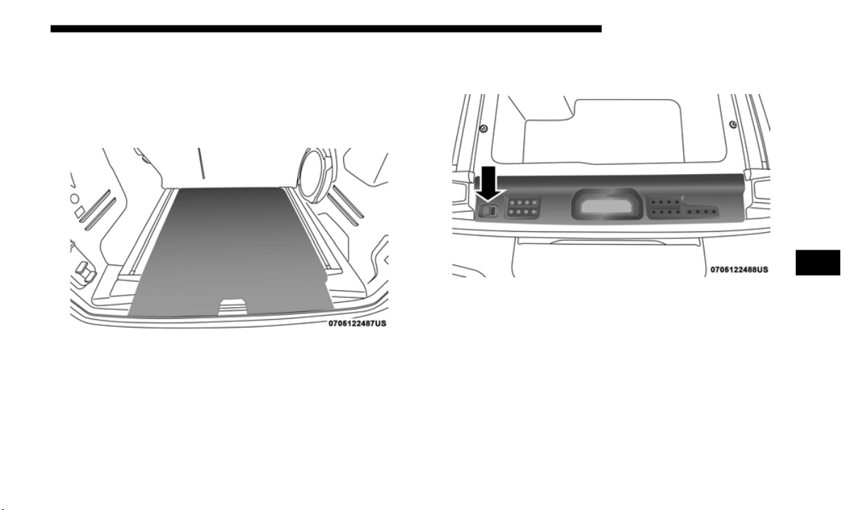
IN CASE OF EMERGENCY 433
Jack Location
The jack and lug wrench are located in the rear cargo area. To
remove jack and tools proceed as follows:
1. Lift the load floor in the cargo area.
Load Floor
N
OTE:
The load floor can be removed for easier access by pulling
the load
floor directly rearward.
2. Remove the hardware storage cover by pinching the latch
on the
left side and pulling upward.
Hardware Storage Cover Latch
6

434 IN CASE OF EMERGENCY
Jack And Lug Wrench
3. Turn the black plastic wing nut counterclockwise to
loosen
the jack from the storage bin.
Plastic Wing Nut Location
4. Remove tool kit and assemble tools.
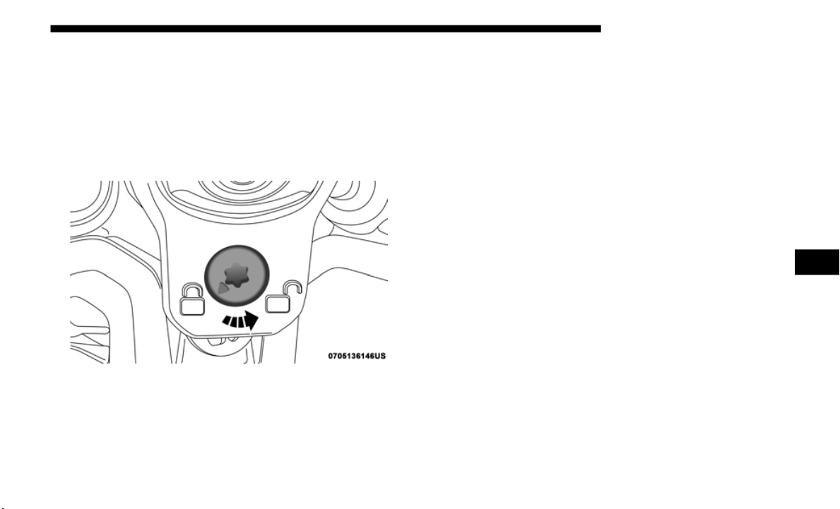
IN CASE OF EMERGENCY 435
Spare Tire Removal
1. To remove the spare tire from the carrier, remove the tire
cover, if equipped.
2. Remove the Rear Camera Cover by turning the lock bolt
to the
left with the #T40 Torx head driver and ratchet
from the
supplied tool kit.
Unlock Rear Camera Cover
3. Remove the lug nuts with the lug wrench turning them
counter
clockwise. If equipped, remove the locking lug
nut with the lock key (located in the glove box) turning it
counterclockwise.
Stowing The Replaced Spare Tire
1. Mount the spare tire onto the carrier. Torque down lug
nuts an
d locking lug nut.
2. R
eturn the lock bolt to the lock position on the camera
c
over b
y turning the lock to the right using the provided
#T40
Torx head driver and ratchet. Then, reinstall the
camera c
over by slipping it over the camera/tire carrier
until it snaps into place.
3. Reinstall the tire cover if applicable.
NOTE:
If
you have added aftermarket accessories to the spare tire
m
ounted
carrier, it cannot exceed a gross weight of 85 lbs
(38.5 kg) including the weight of the spare tire.
6

436 IN CASE OF EMERGENCY
(Continued)
Preparations For Jacking
1. Park on a firm, level surface. Avoid ice or slippery areas.
2. Turn on the Hazard Warning flasher.
3. Appl
y the parking brake.
4. Shif
t the automatic transmission into PARK, or a manual
transm
ission into REVERSE.
5. Turn the ignition OFF.
6. Bloc
k both the front and rear of the wheel diagonally
opposi
te the jacking position. For example, if the right
front wheel is being changed, block the left rear wheel.
NOTE:
Passengers should not remain in the vehicle when the
v
ehicle
is being jacked.
Jacking Instructions
WARNING!
Do not attempt to change a tire on the side of the vehicle
close to
moving traffic. Pull far enough off the road to
avoid being hit when operating the jack or changing the
wheel.
WARNING!
Carefully follow these tire changing warnings to help
prevent
personal injury or damage to your vehicle:
• Always park on a firm, level surface as far from the
edge of
the roadway as possible before raising the
vehicle.
• Turn on the Hazard Warning flashers.
• Block t
he wheel diagonally opposite the wheel to be
raised
.
• Apply the parking brake firmly and shift an automatic
transm
ission in PARK; a manual transmission to
REVERSE.
• Never start or run the engine with the vehicle on a jack.
• Do not l
et anyone sit in the vehicle when it is on a jack.
• Do not ge
t under the vehicle when it is on a jack. If you
need t
o get under a raised vehicle, take it to a service
center where it can be raised on a lift.
• Only use the jack in the positions indicated and for
liftin
g this vehicle during a tire change.
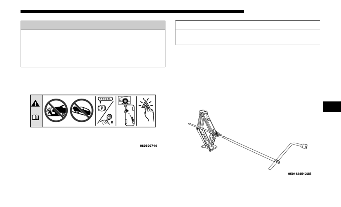
IN CASE OF EMERGENCY 437
Jack Warning Label
1. Remove the spare tire, jack and tools from the stored location.
2. Loose
n (but do not remove) the wheel lug nuts by turning
them to
the left one turn while the wheel is still on the
ground.
3. Assemble the jack and jacking tools. Connect the jack
handle
driver to the extension, then to the lug wrench.
Assembled Jack And Tools
• If working on or near a roadway, be extremely careful
of motor t
raffic.
• To assure that spare tires, flat or inflated, are securely
stowed,
spares must be stowed with the valve stem
facing the ground.
WARNING! (Continued)
CAUTION!
Do not attempt to raise the vehicle by jacking on
locations
other than those indicated.
6
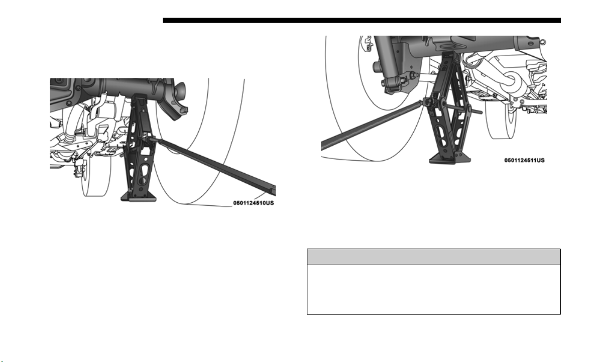
438 IN CASE OF EMERGENCY
4. Operate the jack from the front or the rear of the vehicle.
Place the jack under the axle tube, as shown. Do not raise
the vehicle until you are sure the jack is fully engaged.
Front Jacking Location
Rear Jacking Location
5. Raise the vehicle by turning the jack screw clockwise.
Raise t
he vehicle only until the tire just clears the surface
and enough clearance is obtained to install the spare tire.
Minimum tire lift provides maximum stability.
WARNING!
Raising the vehicle higher than necessary can make the
vehicle l
ess stable. It could slip off the jack and hurt
someone near it. Raise the vehicle only enough to
remove the tire.

IN CASE OF EMERGENCY 439
6. Remove the lug nuts and wheel.
7. Position the spare wheel/tire on the vehicle and install
the lu
g nuts with the cone-shaped end toward the wheel.
Lightly tighten the lug nuts clockwise.
8. Lower the vehicle by turning the jack screw to the left,
and re
move the jack.
9. Finish tightening the lug nuts. Push down on the wrench
while t
ightening for increased leverage. Alternate nuts
until each nut has been tightened twice. Refer to “Torque
Specifications” in “Technical Specifications” for correct
lug nut torque.
10. Remove the jack assembly and wheel blocks.
11. Sec
ure the jack and tools in their proper locations.
12. Sec
ure the damaged wheel/tire on the spare tire carrier.
Torque
down lug nuts and locking lug nut.
13. Return the lock bolt to the lock position on the camera
cover
by turning the lock to the right using the provided
#40
Torx head driver and ratchet. Then, reinstall the
camera
cover by slipping it over the camera/tire carrier
until it snaps into place.
WARNING!
To avoid the risk of forcing the vehicle off the jack, do
not tight
en the wheel nuts fully until the vehicle has
been lowered. Failure to follow this warning may result
in serious injury.
WARNING!
A loose tire or jack thrown forward in a collision or hard
stop, cou
ld endanger the occupants of the vehicle.
Always stow the jack parts and the spare tire in the
places provided.
6

440 IN CASE OF EMERGENCY
Road Tire Installation
1. Mount the road tire on the axle.
2. Install the remaining lug nuts with the cone shaped end
of the
nut toward the wheel. Lightly tighten the lug nuts.
3. Lower the vehicle to the ground by turning the jack
handle
counterclockwise.
4. Finish tightening the lug nuts. Push down on the wrench
while
at the end of the handle for increased leverage.
Tighten the lug nuts in a star pattern until each nut has been
tightened twice. For the correct lug nut torque refer to
“Torque Specifications” in “Technical Specifications”. If in
doubt about the correct tightness, have them checked with
a torque wrench by an authorized dealer or service station.
5. After 25 miles
(40 km), check the lug nut torque with a
torque wrench to ensure that all lug nuts are properly
seated against the wheel.
MANUAL PARK RELEASE
To push or tow the vehicle in cases where the transmission
will not shift out of PARK (such as a dead battery), a Manual
Park Release is available.
Follow these steps to use the Manual Park Release:
1. Firmly apply the parking brake.
2. Remo
ve the manual park release cover, located above the
gear se
lector, to access the release tether strap.
WARNING!
To avoid the risk of forcing the vehicle off the jack, do
not tight
en the wheel nuts fully until the vehicle has
been lowered. Failure to follow this warning may result
in serious injury.
WARNING!
Always secure your vehicle by fully applying the
parking
brake before activating the Manual Park
Release. In addition, you should be seated in the driver’s
seat with your foot firmly on the brake pedal when
activating the Manual Park Release. Activating the
Manual Park Release will allow your vehicle to roll away
if it is not secured by the parking brake, or by proper
connection to a tow vehicle. Activating the Manual Park
Release on an unsecured vehicle could lead to serious
injury or death for those in or around the vehicle.
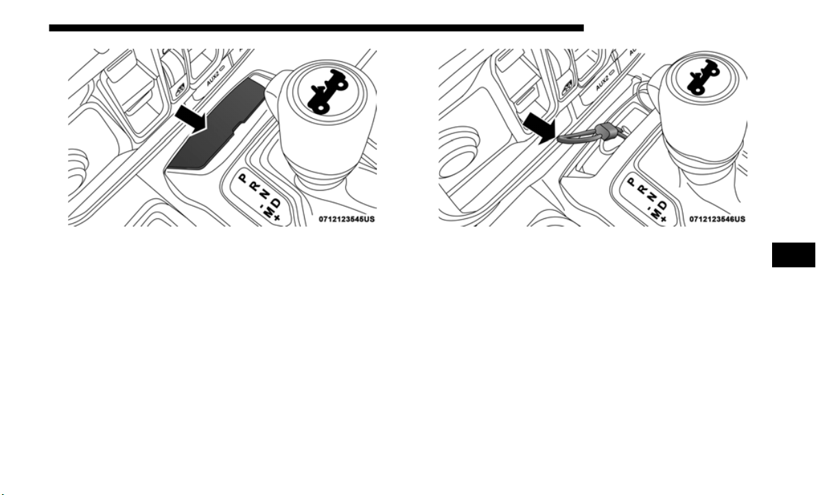
IN CASE OF EMERGENCY 441
Manual Park Release Cover
3. Using a small screwdriver or similar tool, fish the tether
strap u
p through the opening in the console base.
Tether Strap
4. Press and maintain firm pressure on the brake pedal.
5. Pull the tether strap up and to the left until the release
lever l
ocks into place in the vertical position. The vehicle
is now out of PARK and can be moved. Release the
parking brake only when the vehicle is securely
connected to a tow vehicle.
6

442 IN CASE OF EMERGENCY
To Reset The Manual Park Release:
1. Pull upward on the tether strap, releasing it from the
“locked
” position.
2. L
ower the Manual Park Release lever downward and to
t
he ri
ght, into its original position.
3. Tuck the tether strap into the base of the console, and
reinst
all the cover.
JUMP STARTING
If your vehicle has a discharged battery, it can be jump
started using a set of jumper cables and a battery in another
vehicle, or by using a portable battery booster pack. Jump
starting can be dangerous if done improperly, so please
follow the procedures in this section carefully.
NOTE:
When using a portable battery booster pack, follow the
m
anufac
turer's operating instructions and precautions.
WARNING!
Do not attempt jump starting if the battery is frozen. It
could ru
pture or explode and cause personal injury.
CAUTION!
Do not use a portable battery booster pack or any other
b
ooster
source with a system voltage greater than 12 Volts or
damage to the battery, starter motor, alternator or electrical
system may occur.
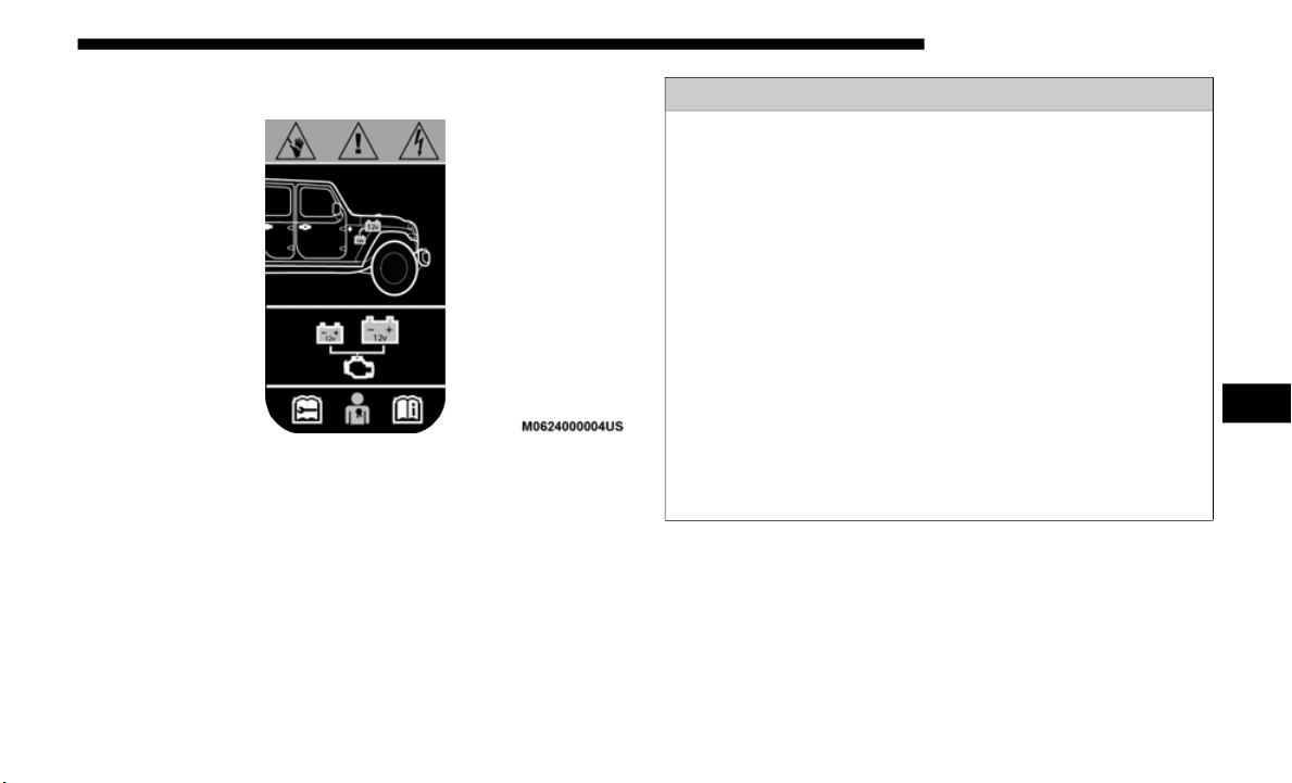
IN CASE OF EMERGENCY 443
Preparations For Jump Start
Supplemental Battery — If Equipped
WARNING!
• Only use the positive battery post on the main battery
to jump
start your vehicle. Serious injury or death
could result if you attempt to jump start using the
supplemental battery.
• Battery gas is flammable and explosive. Keep flame or
sparks
away from the battery. Do not use a booster
battery or any other booster source with an output
greater than 12 Volts. Do not allow cable clamps to
touch each other.
• Battery posts, terminals, and related accessories contain
lead an
d lead compounds. Wash hands after handling.
• If a “fast charger” is used while the battery is in the
vehicle,
disconnect both vehicle battery cables before
connecting the charger to the battery. Do not use a “fast
charger” to provide starting.
6
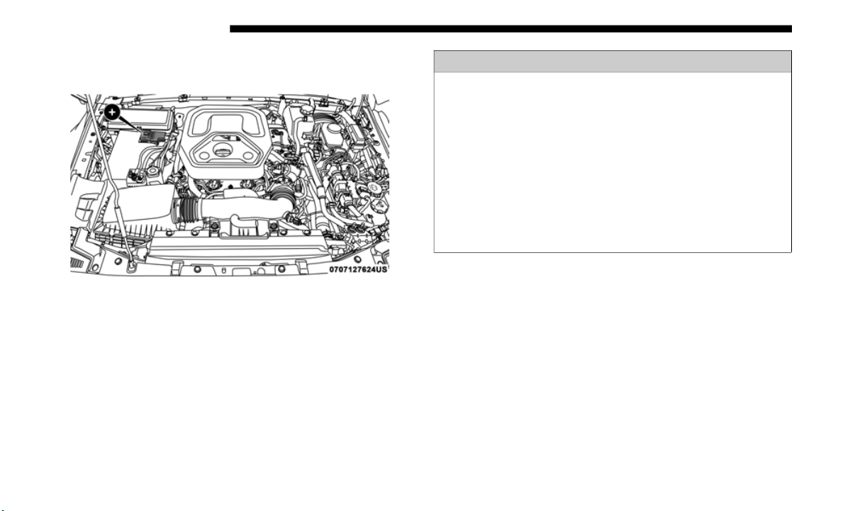
444 IN CASE OF EMERGENCY
The battery in your vehicle is located in the right rear of the
engine compartment, behind the Power Distribution Center.
Positive Battery Post
NOTE:
The positive battery post is covered with a protective cap.
L
ift up
on the cap to gain access to the post.
If your vehicle is equipped with a Stop/Start system, it will
be equip
ped with two batteries. Refer to “Stop/Start System
— If Equipped” in “Starting and Operating” for further
information.
1. Apply the parking brake, shift the automatic transmis-
sion in
to PARK (manual transmission in NEUTRAL) and
turn the
ignition OFF.
2. Apply the parking brake, shift the automatic transmis-
sion in
to PARK and turn the ignition OFF.
3. T
urn off the heater, radio, and all unnecessary electrical
accesso
ries.
4. If using another vehicle to jump start the battery, park the
vehicle
within the jumper cable’s reach, apply the
parking brake and make sure the ignition is OFF.
WARNING!
• Take care to avoid the radiator cooling fan whenever
the hood
is raised. It can start anytime the ignition
switch is ON. You can be injured by moving fan blades.
• Remove any metal jewelry such as rings, watch bands
and bra
celets that could make an inadvertent electrical
contact. You could be seriously injured.
• Batteries contain sulfuric acid that can burn your skin
or eyes a
nd generate hydrogen gas which is flammable
and explosive. Keep open flames or sparks away from
the battery.

IN CASE OF EMERGENCY 445
Jump Starting Procedure
NOTE:
Make sure at all times that unused ends of jumper cables are
not con
tacting each other or either vehicle while making
connections.
Connecting The Jumper Cables
1. Connect the positive (+) end
of the jumper cable to the
remote positive (+) post of the discharged vehicle.
2. C
onnect the opposite end of the positive (
+) jump
er cable
to the positive (+) post of the booster battery.
3. Connect the negative end (-) of
the jumper cable to the
negative (-) post of the booster battery.
4. Connect the opposite end of the negative (-) jum
per cable
to a good engine ground (exposed metal part of the
discharged vehicle’s engine) away from the battery and
the fuel injection system.
WARNING!
Do not allow vehicles to touch each other as this could
establi
sh a ground connection and personal injury could
result.
WARNING!
Failure to follow this jump starting procedure could
result
in personal injury or property damage due to
battery explosion.
CAUTION!
Failure to follow these procedures could result in
damage t
o the charging system of the booster vehicle or
the discharged vehicle.
WARNING!
Do not connect the jumper cable to the negative (-) post
of the d
ischarged battery. The resulting electrical spark
could cause the battery to explode and could result in
personal injury. Only use the specific ground point, do
not use any other exposed metal parts.
6

446 IN CASE OF EMERGENCY
5. Start the engine in the vehicle that has the booster battery,
let the engine idle a few minutes, and then start the
engine in the vehicle with the discharged battery.
6. Once the engine is started, remove the jumper cables in
the re
verse sequence:
Disconnecting The Jumper Cables
1. Disconnect the negative (-) end
of the jumper cable from
the engine ground of the vehicle with the discharged
battery.
2. Disconnect the opposite end of the negative (-) jum
per
cable from the negative (-) post of the booster battery.
3. Disconnect the positive (+) end
of the jumper cable from
the positive (+) post of the booster battery.
4. Disconnect the opposite end of the positive (+) jump
er
cable from the remote positive (+) post of the discharged
vehicle.
5. Reinstall the protective cover over the remote positive (+)
post
of the discharged vehicle.
If frequent jump starting is required to start your vehicle you
should
have the battery and charging system tested at an
authorized dealer.
CAUTION!
Do not run the booster vehicle engine above 2,000 rpm
since i
t provides no charging benefit, wastes fuel, and
can damage booster vehicle engine.
CAUTION!
Accessories plugged into the vehicle power outlets draw
power fr
om the vehicle’s battery, even when not in use
(i.e., cellular devices, etc.). Eventually, if plugged in long
enough without engine operation, the vehicle’s battery
will discharge sufficiently to degrade battery life and/or
prevent the engine from starting.

IN CASE OF EMERGENCY 447
IF YOUR ENGINE OVERHEATS
In any of the following situations, you can reduce the poten-
tial for overheating by taking the appropriate action.
• O
n the highways — slow down.
• In cit
y traffic — while stopped, shift transmission into
NEUTRA
L, but do not increase engine idle speed.
NOTE:
There are steps that you can take to slow down an impending
o
verhea
t condition:
• If your air conditioner (A/C) is on, turn it off. The A/C
system
adds heat to the engine cooling system and turning
the A/C off can help remove this heat.
• You can also turn the temperature control to maximum
heat,
the mode control to floor and the blower control to
high. This allows the heater core to act as a supplement to
the radiator and aids in removing heat from the engine
cooling system.
FREEING A STUCK VEHICLE
If your vehicle becomes stuck in mud, sand or snow, it can
often be moved using a rocking motion. Turn the steering
wheel right and left to clear the area around the front wheels.
For vehicles with automatic transmission, push and hold the
lock button on the gear selector. Then, shift back and forth
between DRIVE and REVERSE (with automatic transmission)
or SECOND GEAR and REVERSE (with manual transmission),
while gently pressing the accelerator. Use the least amount of
accelerator pedal pressure that will maintain the rocking
motion, without spinning the wheels or racing the engine.
CAUTION!
Driving with a hot cooling system could damage your
vehicle.
If the temperature gauge reads HOT (H), pull
over and stop the vehicle. Idle the vehicle with the air
conditioner turned off until the pointer drops back into
the normal range. If the pointer remains on HOT (H),
and you hear continuous chimes, turn the engine off
immediately and call for service.
WARNING!
You or others can be badly burned by hot engine coolant
(antifr
eeze) or steam from your radiator. If you see or
hear steam coming from under the hood, do not open the
hood until the radiator has had time to cool. Never try to
open a cooling system pressure cap when the radiator or
coolant bottle is hot.
6

448 IN CASE OF EMERGENCY
NOTE:
• For vehicles with automatic transmission: Shifts between
DRIVE
and REVERSE can only be achieved at wheel
speeds of 5
mph (8 km/h) or less. Whenever the transmis-
sion remains in NEUTRAL for more than 2 seconds, you
must pr
ess the brake pedal to engage DRIVE or REVERSE.
• Push the “ESC Off” switch to place the Electronic Stability
Contro
l (ESC) system in “Partial Off” mode before rocking
the vehicle. Refer to “Electronic Brake Control System” in
“Safety” for further information. Once the vehicle has been
freed, push the “ESC Off” switch again to restore “ESC
On” mode.
WARNING!
Fast spinning tires can be dangerous. Forces generated
by exces
sive wheel speeds may cause damage, or even
failure, of the axle and tires. A tire could explode and
injure someone. Do not spin your vehicle's wheels faster
than 30
mph (48 km/h) or for longer than 30 seconds
continuou
sly without stopping when you are stuck and
do not let anyone near a spinning wheel, no matter what
the speed.
CAUTION!
• Racing the engine or spinning the wheels may lead to
transm
ission overheating and failure. Allow the engine
to idle with the transmission in NEUTRAL for at least
one minute after every five rocking-motion cycles. This
will minimize overheating and reduce the risk of clutch
or transmission failure during prolonged efforts to free
a stuck vehicle.
• When “rocking” a stuck vehicle by shifting between
DRIVE/
SECOND GEAR and REVERSE, do not spin
the wheels faster than 15
mph (24 km/h), or drivetrain
damage m
ay result.
• Revving the engine or spinning the wheels too fast may
lead t
o transmission overheating and failure. It can also
damage the tires. Do not spin the wheels above 30
mph
(48 km/h
) while in gear (no transmission shifting occur-
ring).

IN CASE OF EMERGENCY 449
TOWING A DISABLED VEHICLE
This section describes procedures for towing a disabled vehicle using a commercial towing service. If the transmission and
drivetrain are operable, disabled vehicles may also be towed as described under “Recreational Towing” in the “Starting And
Operating” section.
Proper towing or lifting equipment is required to prevent
damage t
o your vehicle. Use only tow bars and other equip-
ment designed for this purpose, following equipment manu-
facturer’s instructions. Use of safety chains is mandatory.
A
ttach
a tow bar or other towing device to main structural
members of the vehicle, not to bumpers or associated
brackets. State and local laws regarding vehicles under tow
must be observed.
If you must use the accessories (wipers, defrosters, etc.)
while be
ing towed, the ignition must be in the ON/RUN
position, not the ACC position.
If the vehicle's battery is discharged, refer to “Manual Park
Release
” in this section for instructions on shifting the auto-
matic transmission out of PARK in order to move the vehicle.
Towing Condition Wheels OFF The Ground 4WD MODELS
Flat Tow NONE
See instructions under “Recreational Towing” in
“
Starti
ng And Operating”.
• Automatic Transmission in PARK
• Man
ual Transmission in gear ( NOT in N
EUTRAL)
• Transfer Case in NEUTRAL
•
Tow in forward direct
ion
Wheel Lift Or Dolly Tow
Front NOT ALLOWED
Rear NOT ALLOWED
Flatbed ALL BEST METHOD
6

450 IN CASE OF EMERGENCY
Four–Wheel Drive Models
The manufacturer recommends towing with all wheels OFF
the ground. Acceptable methods are to tow the vehicle on a
flatbed or with one end of the vehicle raised and the opposite
end on a towing dolly.
If flatbed equipment is not available and the transfer case is
operabl
e, the vehicle may be towed (in the forward direction,
with ALL wheels on the ground), IF the transfer case is in
NEUTRAL (N) and the transmission is in PARK (for auto
-
matic transmissions) or in gear (N
OT in NE
UTRAL, for
manual transmissions). Refer to “Recreational Towing” in
“Starting And Operating” for detailed instructions.
Emergency Tow Hooks — If Equipped
If your vehicle is equipped with tow hooks, they are
mounted in the front and the rear.
NOTE:
For off-road recovery, it is recommended to use both of the
f
ront t
ow hooks to minimize the risk of damage to the
vehicle. Always use an appropriately rated tow strap.
CAUTION!
• D
o not use sling type equipment when towing. Vehicle
damage
may occur.
• When securing the vehicle to a flatbed truck, do not
attach
to front or rear suspension components. Damage
to your vehicle may result from improper towing.
CAUTION!
• Front or rear wheel lifts must not be used (if the
remain
ing wheels are on the ground). Internal damage
to the transmission or transfer case will occur if a front
or rear wheel lift is used when towing.
• Towing this vehicle in violation of the above require-
ments
can cause severe transmission and/or transfer
case da
mage. Damage from improper towing is not
covered under the New Vehicle Limited Warranty.

IN CASE OF EMERGENCY 451
ENHANCED ACCIDENT RESPONSE SYSTEM (EARS)
This vehicle is equipped with an Enhanced Accident
Response System.
Please refer to “Occupant Restraint Systems” in “Safety” for
further
information on the Enhanced Accident Response
System (EARS) function.
EVENT DATA RECORDER (EDR)
This vehicle is equipped with an Event Data Recorder (EDR).
The main purpose of an EDR is to record data that will assist
in understanding how a vehicle’s systems performed under
certain crash or near crash-like situations, such as an air bag
deployment or hitting a road obstacle.
Please refer to “Occupant Restraint Systems” in “Safety” for
further
information on the Event Data Recorder (EDR).
WARNING!
• Do not use a chain for freeing a stuck vehicle. Chains
may bre
ak, causing serious injury or death.
• Stand clear of vehicles when pulling with tow hooks.
Tow str
aps may become disengaged, causing serious
injury.
CAUTION!
Tow hooks are for emergency use only, to rescue a
vehicle
stranded off road. Do not use tow hooks for tow
truck hookup or highway towing. You could damage
your vehicle. Tow straps are recommended when towing
the vehicle, chains may cause vehicle damage.
6

452
SERVICING AND MAINTENANCE
SCHEDULED SERVICING
Your vehicle is equipped with an automatic oil change indicator
system. The oil change indicator system will remind you that it
is time to take your vehicle in for scheduled maintenance.
Based on engine operation conditions, the oil change indicator
message
will illuminate. This means that service is required for
your vehicle. Operating conditions such as frequent short-trips,
trailer tow, extremely hot or cold ambient temperatures will influ
-
ence when the “Change Oil” or “Oil Change Required” message is
d
isplay
ed. Severe Operating Conditions can cause the change oil
message to illuminate as early as 3,500
miles (5,600 km) since last
reset.
Have your vehicle serviced as soon as possible, within the
next 500
miles (805 km).
On vehicles equipped with instrument cluster display, “Oil
Change R
equired” will be displayed and a single chime will
sound, indicating that an oil change is necessary.
On non-instrument cluster display equipped vehicles,
“Change
Oil” will flash in the instrument cluster odometer
and a single chime will sound, indicating that an oil change
is necessary.
An authorized dealer will reset the oil change indicator
message
after completing the scheduled oil change. If a
scheduled oil change is performed by someone other than an
authorized dealer, the message can be reset by referring to
the steps described under “Instrument Cluster Display” in
“Getting To Know Your Instrument Panel” for further infor
-
mation.
NOTE:
Under no circumstances should oil change intervals exceed
1
0,000 m
iles (16,000 km), twelve months or 350 hours of
engine r
un time, whichever comes first. The 350 hours of
engine run or idle time is generally only a concern for fleet
customers.
Severe Duty All Models
Change Engine Oil at 4,000 miles (6,500 km) or 350 hours of
engine r
un time if the vehicle is operated in a dusty and off
road environment or is operated predominately at idle or
only very low engine RPM’s. This type of vehicle use is
considered Severe Duty.

SERVICING AND MAINTENANCE 453
Once A Month Or Before A Long Trip:
• Check engine oil level
• Check wi
ndshield washer fluid level
• Check t
he tire inflation pressures and look for unusual
wear or
damage, rotate at the first sign of irregular wear
• Check the fluid levels of the coolant reservoir, brake
master
cylinder, and power steering, and fill as needed
• Check function of all interior and exterior lights
Maintenance Plan
Required Maintenance Intervals
Refer to the maintenance plan on the following pages for the
require
d maintenance intervals.
At Every Oil Change Interval As Indicated By Oil Change Indicator System:
• C
hange oil and filter
• Rotate
the tires
• Rotate
at the first sign of irregular wear, even if it occurs before the oil indicator system turns on
• Inspec
t battery and clean and tighten terminals as required
• Inspec
t brake pads, shoes, rotors, drums, hoses and park brake
• Inspec
t engine cooling system protection and hoses
• Inspec
t exhaust system
• Inspec
t engine air cleaner if using in dusty or off-road conditions
• Inspec
t all door latches for presence of grease, reapply if necessary.
7

454 SERVICING AND MAINTENANCE
Mileage or time passed
(whichever comes first)
20,000
30,000
40,000
50,
000
60,000
70,
000
80,000
90,000
100,000
110,000
120,000
130,000
140,000
150,000
Or Years: 2 3 4 5 6 7 8 9 10 11 12 13 14 15
Or Kilometers:
32,000
48,000
64,000
80,
000
96,000
112,
000
128,000
144,000
160,000
176,000
192,000
208,000
224,000
240,000
Additional Inspections
Inspect the CV/Universal joints.
X X X X X X X
Inspect front suspension, tie rod
en
ds, an
d replace if necessary.
X X X X X X X
Inspect the front and rear axle
fluid.
X X X X
In
spect the brake linings, replace
as necess
ary
X X X X X X X
Adjust parking brake on vehicles
equipped
with four wheel disc
brakes.
X X X X X X X
Inspect transfer case fluid. X X X
Additional Maintenance
Replace engine air cleaner filter.
X X X X X
Replace air conditioning/cabin
air fil
ter.
X X X X X X X

SERVICING AND MAINTENANCE 455
Replace Spark Plugs –
2.0L Engine
1
X X
Replace spark plugs –
3.6L Engine
2
X
Flush and replace the engine,
intercoo
ler (if equipped), battery
(if equipped), and Motor
Generator Unit (MGU) (if
equipped) coolant at 10 years or
150,000
miles (240,000 km)
whichever
comes first.
X X
Mileage or time passed
(whichever comes first)
20,000
30,000
40,000
50,000
60,000
70,000
80,000
90,000
100,000
110,000
120,000
130,000
140,000
150,000
Or Years: 2 3 4 5 6 7 8 9 10 11 12 13 14 15
Or Kilometers:
32,000
48,000
64,000
80,000
96,000
112,000
128,000
144,000
160,000
176,000
192,000
208,000
224,000
240,000
7

456 SERVICING AND MAINTENANCE
Change the manual transmission
fluid if using your vehicle for
any of the following: trailer
towing, snow plowing, heavy
loading, taxi, police, delivery
service (commercial service),
off-road, desert operation or
more than 50% of your driving is
at sustained high speeds during
hot weather, above 90°F (32°C).
X X X X X
Change transfer case fluid if
using you
r vehicle for any of
the following: police, taxi, fleet,
or frequent trailer towing.
X X
Inspect and replace PCV valve
if nece
ssary.
X
Mileage or time passed
(whichever comes first)
20,000
30,000
40,000
50,000
60,000
70,000
80,000
90,000
100,000
110,000
120,000
130,000
140,000
150,000
Or Years: 2 3 4 5 6 7 8 9 10 11 12 13 14 15
Or Kilometers:
32,000
48,000
64,000
80,000
96,000
112,000
128,000
144,000
160,000
176,000
192,000
208,000
224,000
240,000

SERVICING AND MAINTENANCE 457
Heavy Duty Use Of The Vehicle
Change engine oil at 4,000 miles (6,500 km) or 350 hours of
engine run time if the vehicle is operated in a dusty and off
road environment or is operated predominately at idle or
only very low engine RPM’s. This type of vehicle use is
considered Severe Duty.
Change front and rear axle
fluid i
f using your vehicle for
police, taxi, fleet, off-road or
frequent trailer towing.
X X X
1. The spark plug change interval is mileage based only, yearly intervals do not apply.
2. The spark plug change interval is mileage based only, yearly intervals do not apply.
Mileage or time passed
(whichever comes first)
20,000
30,000
40,000
50,000
60,000
70,000
80,000
90,000
100,000
110,000
120,000
130,000
140,000
150,000
Or Years: 2 3 4 5 6 7 8 9 10 11 12 13 14 15
Or Kilometers:
32,000
48,000
64,000
80,000
96,000
112,000
128,000
144,000
160,000
176,000
192,000
208,000
224,000
240,000
WARNING!
• You can be badly injured working on or around a motor
vehicle
. Do only service work for which you have the
knowledge and the right equipment. If you have any
doubt about your ability to perform a service job, take
your vehicle to a competent mechanic.
• Failure to properly inspect and maintain your vehicle could
result
in a component malfunction and effect vehicle
handling and performance. This could cause an accident.
7

458 SERVICING AND MAINTENANCE
ENGINE COMPARTMENT
2.0L Engine
1 — Power Distribution Center (Fuses) 8 — Power Pack Unit Pressure Cap — If Equipped
2 — Battery 9 — Power Pack Unit Pressure Reservoir — If Equipped
3 — Engine Oil Dipstick 10 — Washer Fluid Reservoir
4 — Engine Oil Fill
11 — Intercooler/Motor Generator Unit Coolant Pressure Cap — If Equipped
5 — Engine Coolant Reservoir
12 — Intercooler/Motor Generator Unit Coolant Reservoir — If Equipped
6 — Engine Coolant Pressure Cap 13 — Power Steering Fluid Reservoir
7 — Brake Fluid Reservoir 14 — Engine Air Cleaner
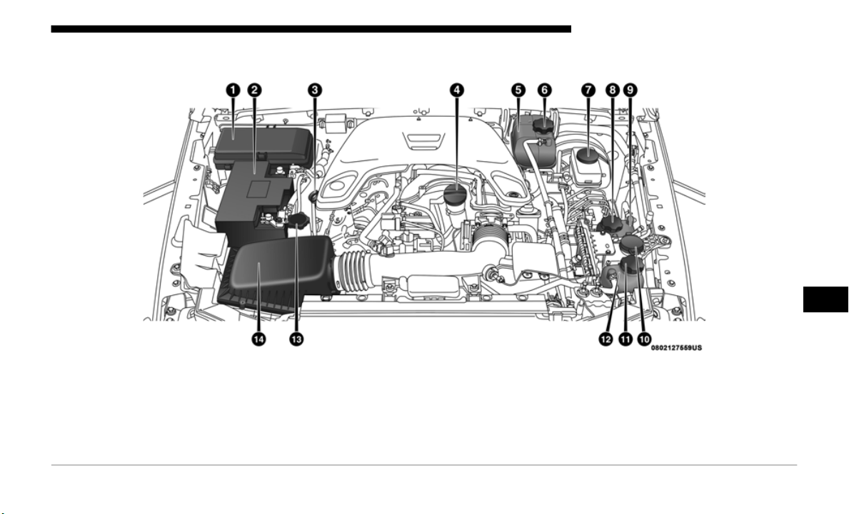
SERVICING AND MAINTENANCE 459
3.6L Engine
1 — Power Distribution Center (Fuses) 8 — Power Pack Unit Pressure Cap — If Equipped
2 — Battery 9 — Power Pack Unit Pressure Reservoir — If Equipped
3 — Engine Oil Dipstick 10 — Washer Fluid Reservoir
4 — Engine Oil Fill 11 — Motor Generator Unit Coolant Pressure Cap — If Equipped
5 — Engine Coolant Reservoir 12 — Motor Generator Unit Coolant Reservoir — If Equipped
6 — Engine Coolant Pressure Cap 13 — Power Steering Fluid Reservoir
7 — Brake Fluid Reservoir 14 — Engine Air Cleaner
7

460 SERVICING AND MAINTENANCE
Checking Oil Level
To ensure proper lubrication of your vehicle's engine, the
engine oil must be maintained at the correct level. The engine
oil level should be checked five minutes after a warmed up
engine has been shut off.
Checking the oil while the vehicle is on level ground will
improve
the accuracy of the oil level readings. Always main-
tain the oil level within the SAFE zone on the dipstick.
A
dding 1
quart (0.95 liters) of oil when the reading is at the
bottom of the crosshatch zone will result in a reading at the
top of the crosshatch zone on these engines.
Adding Washer Fluid
The fluid reservoir for the windshield washers and the rear
window washer (if equipped) is shared. The fluid reservoir
is located in the engine compartment. Be sure to check the
fluid level at regular intervals. Fill the reservoir with wind
-
shield washer solvent only (not radiator antifreeze). When
r
efilli
ng the washer fluid reservoir, take some washer fluid
and apply it to a cloth or towel and wipe clean the wiper
blades; this will help blade performance.
To prevent freeze-up of your windshield washer system in
cold wea
ther, select a solution or mixture that meets or
exceeds the temperature range of your climate. This rating
information can be found on most washer fluid containers.
CAUTION!
Overfilling or underfilling the crankcase will cause
a
eration
or loss of oil pressure. This could damage your
engine.
WARNING!
Commercial windshield washer solvents are flammable.
They coul
d ignite and burn you. Care must be exercised
when filling or working around the washer solution.
SERVICING AND MAINTENANCE 461
(Continued)
Maintenance-Free Battery
Your vehicle is equipped with a maintenance-free battery.
You will never have to add water, nor is periodic mainte-
nance required.
WARNING!
• Battery fluid is a corrosive acid solution and can burn
or even
blind you. Do not allow battery fluid to contact
your eyes, skin, or clothing. Do not lean over a battery
when attaching clamps. If acid splashes in eyes or on
skin, flush the area immediately with large amounts of
water. Refer to “Jump Starting Procedure” in “In Case
Of Emergency” for further information.
• Battery gas is flammable and explosive. Keep flame or
sparks
away from the battery. Do not use a booster
battery or any other booster source with an output
greater than 12 Volts. Do not allow cable clamps to
touch each other.
• Battery posts, terminals, and related accessories contain
lead a
nd lead compounds. Wash hands after handling.
• Vehicles with the Stop/Start system will be equipped
with t
wo batteries. Bot the main and the supplemental
batteries must be disconnected to completely de-ener
-
gize the 12 volt electrical system.
• Serious injury or death could result if you do not
disconnect both batteries. To learn how to properly
disconnect, see your authorized dealer.
CAUTION!
• It is essential when replacing the cables on the battery
that t
he positive cable is attached to the positive post and
the negative cable is attached to the negative post. Battery
posts are marked positive (+) and negative (-) and are
identified on the battery case. Cable clamps should be
tight on the terminal posts and free of corrosion.
• If a “fast charger” is used while the battery is in the
vehicle
, disconnect both vehicle battery cables before
connecting the charger to the battery. Do not use a “fast
charger” to provide starting voltage.
• Vehicles with the Stop/Start system will be equipped
with t
wo batteries. Both the main and the supplemental
batteries must be disconnected to completely de-ener
-
gize the 12 volt electrical system.
• I
f the negative battery cables are not isolated properly it
can ca
use a potential power spike or surge in the system,
resulting in damage to essential electrical components.
WARNING! (Continued)
7

462 SERVICING AND MAINTENANCE
DEALER SERVICE
An authorized dealer has the qualified service personnel,
special tools, and equipment to perform all service opera-
tions in an expert manner. Service Manuals are available
wh
ich in
clude detailed service information for your vehicle.
Refer to these Service Manuals before attempting any proce
-
dure yourself.
NOTE:
Intentional tampering with emissions control systems may
v
oid you
r warranty and could result in civil penalties being
assessed against you.
Engine Oil
Change Engine Oil — Gasoline Engine
Refer to “Maintenance Plan” in this section for the proper
mainten
ance intervals.
NOTE:
Under no circumstances should oil change intervals exceed
1
0,000 m
iles (16,000 km), 12 months or 350 hours of engine
run tim
e, whichever comes first. The 350 hours of engine run
or idle time is generally only a concern for fleet customers.
Engine Oil Selection — 2.0L Engine
For best performance and maximum protection under all
types of
operating conditions, the manufacturer only recom-
mend engine oils that are API SN PLUS certified and meet
t
he req
uirements of FCA Material Standard MS-13340. An
equivalent full synthetic engine oil can be used if it meets
API SN PLUS Certification. If SN PLUS or equivalent oil is
unavailable then please contact your local dealership for
recommendation.
WARNING!
You can be badly injured working on or around a motor
vehicle.
Only do service work for which you have the
knowledge and the proper equipment. If you have any
doubt about your ability to perform a service job, take
your vehicle to a competent mechanic.

SERVICING AND MAINTENANCE 463
Engine Oil Selection 3.6L Engine
For best performance and maximum protection under all
types of
operating conditions, the manufacturer only recom-
mends engine oils that are API Certified and meet the
r
equire
ments of FCA Material Standard MS-6395.
American Petroleum Institute (API) Engine Oil
Id
en
tification
Symbol
This symbol means that the oil has been certified by
the American Petroleum Institute (API). The manu-
facturer only recommends API Certified engine oils.
This symbol certifies 0W-20, 5W-20, 0W-30, 5W-30 and
1
0W-30
engine oils.
Engine Oil Viscosity (SAE Grade) — 2.0L Engine
Mopar
API SN PLUS Certified SAE 5W-30 Full Synthetic
Engine O
il which meets the requirements of FCA Material
Standard MS-13340 is recommended for all operating
temperatures. This engine oil improves low temperature
starting and vehicle fuel economy.
The engine oil filler cap also shows the recommended engine
oil vis
cosity for your engine. For information on engine oil
filler cap location, refer to the “Engine Compartment” illus
-
tration in this section.
Lubricants which do not have both the engine oil certifica-
tion mark and the correct SAE viscosity grade number
s
hould
not be used.
CAUTION!
Do not use chemical flushes in your engine oil as the
c
hemica
ls can damage your engine. Such damage is not
covered by the New Vehicle Limited Warranty.
CAUTION!
Failure to use the recommended SN PLUS or equivalent
oil can
cause engine damage not covered by the vehicle
warranty.
7

464 SERVICING AND MAINTENANCE
Engine Oil Viscosity (SAE Grade) — 3.6L Engine
Mopar SAE 0W-20 engine oil approved to FCA Material
Standar
d MS-6395 such as Pennzoil, Shell Helix or equiva-
lent is recommended for all operating temperatures. This
e
ngine o
il improves low temperature starting and vehicle
fuel economy.
The engine oil filler cap also shows the recommended engine
oil vis
cosity for your engine. For information on engine oil
filler cap location, refer to the “Engine Compartment” illus
-
tration in this section.
Lubricants which do not have both the engine oil certifica-
tion mark and the correct SAE viscosity grade number
s
hould
not be used.
Synthetic Engine Oils
You may use synthetic engine oils provided the recom-
mended oil quality requirements are met, and the recom-
mended maintenance intervals for oil and filter changes are
f
ollowed
.
Synthetic engine oils which do not have both the engine oil
certifi
cation mark and the correct SAE viscosity grade
number should not be used.
Materials Added To Engine Oil
The manufacturer strongly recommends against the addi-
tion of any additives (other than leak detection dyes) to the
e
ngine o
il. Engine oil is an engineered product and its perfor-
mance may be impaired by supplemental additives.
Disposing Of Used Engine Oil And Oil Filters
Care should be taken in disposing of used engine oil and oil
f
ilters
from your vehicle. Used oil and oil filters, indiscrimi-
nately discarded, can present a problem to the environment.
C
ontact
an authorized dealer, service station or govern-
mental agency for advice on how and where used oil and oil
f
ilters
can be safely discarded in your area.
Engine Oil Filter
The engine oil filter should be replaced with a new filter at
every engine oil change.
Engine Oil Filter Selection
This manufacturer's engines have a full-flow type disposable oil
f
ilter.
Use a filter of this type for replacement. The quality of
replacement filters varies considerably. Only high quality filters
should be used to assure most efficient service. Mopar engine oil
filters are high quality oil filters and are recommended.

SERVICING AND MAINTENANCE 465
Engine Air Cleaner Filter
Refer to the “Maintenance Plan” in this section for the proper
maintenance intervals.
NOTE:
Be sure to follow the “Severe Duty Conditions” maintenance
i
nterval
if applicable.
Engine Air Cleaner Filter Selection
The quality of replacement engine air cleaner filters varies
consider
ably. Only high quality filters should be used to
assure most efficient service. Mopar engine air cleaner filters
are a high quality filter and are recommended.
Engine Air Cleaner Filter Inspection and Replacement —
Gasoline Engine
Fo
llow the recommended maintenance intervals as shown in
the Main
tenance Schedule in this section.
Engine Air Cleaner Filter Removal
1. L
oosen the retainers from the air cleaner cover using a
s
uitabl
e tool.
Air Cleaner Filter Cover
WARNING!
The air induction system (air cleaner, hoses, etc.) can
provide a
measure of protection in the case of engine
backfire. Do not remove the air induction system (air
cleaner, hoses, etc.) unless such removal is necessary for
repair or maintenance. Make sure that no one is near the
engine compartment before starting the vehicle with the
air induction system (air cleaner, hoses, etc.) removed.
Failure to do so can result in serious personal injury.
1 — Retainers
2 — Air Filter Cover
7
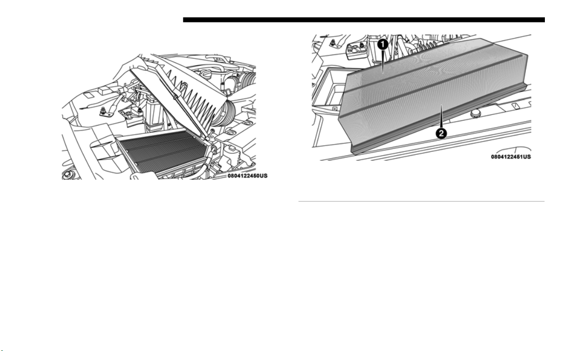
466 SERVICING AND MAINTENANCE
2. Lift the air cleaner cover to access the air cleaner filter.
Air Cleaner Filter Cover
3. Remove the air cleaner filter element from the housing
assembl
y.
Air Cleaner Filter
Engine Air Cleaner Filter Installation
NOTE:
Inspect and clean the housing if dirt or debris is present
before r
eplacing the air filter element.
1. I
nstall the air cleaner filter element into the housing
a
ssembl
y with the air cleaner filter inspection surface
facing downward.
2. Tighten air cleaner cover retainers using a suitable tool.
1 — Air Cleaner Filter Inspection Surface
2 — Air Cleaner Filter
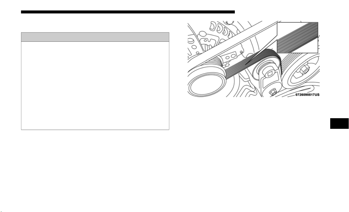
SERVICING AND MAINTENANCE 467
Accessory Drive Belt Inspection
When inspecting accessory drive belts, small cracks that run
across ribbed surface of belt from rib to rib, are considered
normal. These are not a reason to replace belt. However,
cracks running along a rib (not across) are not normal. Any
belt with cracks running along a rib must be replaced. Also
have the belt replaced if it has excessive wear, frayed cords
or severe glazing.
Accessory Belt (Serpentine Belt)
Conditions that would require replacement:
• R
ib chunking (one or more ribs has separated from belt body)
• Rib or
belt wear
• Longitud
inal belt cracking (cracks between two ribs)
• Belt sl
ips
• “Groove
jumping" (belt does not maintain correct position
on pull
ey)
WARNING!
• Do not attempt to inspect an accessory drive belt with
vehicle
running.
• When working near the radiator cooling fan, discon-
nect th
e fan motor lead. The fan is temperature
controlled
and can start at any time regardless of igni-
tion mode. You could be injured by the moving fan
b
lades.
• Y
ou can be badly injured working on or around a motor
vehicle.
Only do service work for which you have the
knowledge and the proper equipment. If you have any
doubt about your ability to perform a service job, take
your vehicle to a competent mechanic.
7

468 SERVICING AND MAINTENANCE
• Belt broken (note: identify and correct problem before new
belt is installed)
• Noise (objectionable squeal, squeak, or rumble is heard or
felt wh
ile drive belt is in operation)
Some conditions can be caused by a faulty component such
as a be
lt pulley. Belt pulleys should be carefully inspected for
damage and proper alignment.
Belt replacement on some models requires the use of special
tools,
we recommend having your vehicle serviced at an
authorized dealer.
Air Conditioner Maintenance
For best possible performance, your air conditioner should
be checked and serviced by an authorized dealer at the start
of each warm season. This service should include cleaning of
the condenser fins and a performance test. Drive belt tension
should also be checked at this time.
WARNING!
• Use only refrigerants and compressor lubricants
approved
by the manufacturer for your air condi-
tioning system. Some unapproved refrigerants are
f
lammab
le and can explode, injuring you. Other unap-
proved refrigerants or lubricants can cause the system
t
o fail,
requiring costly repairs. Refer to Warranty Infor-
mation Book, located in your owner’s information kit,
f
or furt
her warranty information.
• The air conditioning system contains refrigerant under
high pr
essure. To avoid risk of personal injury or
damage to the system, adding refrigerant or any repair
requiring lines to be disconnected should be done by
an experienced technician.
CAUTION!
Do not use chemical flushes in your air conditioning
system a
s the chemicals can damage your air
conditioning components. Such damage is not covered
by the New Vehicle Limited Warranty.

SERVICING AND MAINTENANCE 469
Refrigerant Recovery And Recycling R-134a — If
Equipped
R-134a Air Conditioning Refrigerant is a hydrofluorocarbon
(HFC) th
at is an ozone-friendly substance. The manufacturer
recommends that air conditioning service be performed by
an authorized dealer or other service facilities using recovery
and recycling equipment.
NOTE:
Use only manufacturer approved A/C system PAG
compres
sor oil and refrigerants.
Refrigerant Recovery And Recycling — R–1234yf
R–1234yf Air Conditioning Refrigerant is a hydrofluo-
roolefin (HFO) that is endorsed by the Environmental
P
rotect
ion Agency and is an ozone-friendly substance with a
low global-warming potential. The manufacturer recom
-
mends that air conditioning service be performed by an
authori
zed dealer using recovery and recycling equipment.
NOTE:
Use only manufacturer approved A/C system PAG
c
ompres
sor oil, and refrigerants.
Air Conditioning Filter Replacement (A/C Air Filter)
The A/C air filter is located in the fresh air inlet behind the
glove co
mpartment. Perform the following procedure to
replace the filter:
1. Open the glove compartment and remove all contents.
WARNING!
Do not remove the cabin air filter while the vehicle is
running
, or while the ignition is in the ACC or ON/RUN
mode. With the cabin air filter removed and the blower
operating, the blower can contact hands and may propel
dirt and debris into your eyes, resulting in personal
injury.
7
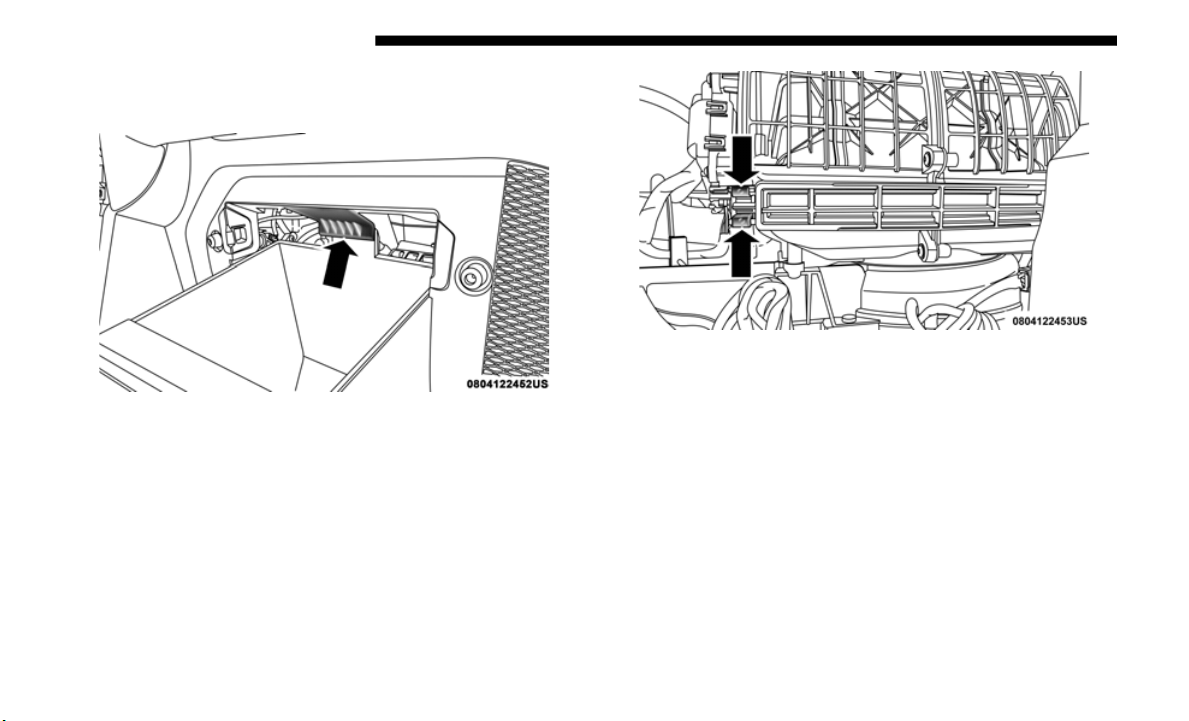
470 SERVICING AND MAINTENANCE
2. Push up on the glove compartment travel stop and lower
the door.
Glove Compartment Travel Stop
3. Pivot the glove compartment downward.
4. Disen
gage the two retaining tabs that secure the air filter
access
door to the HVAC housing.
Air Filter Retaining Tabs
5. Remove the air filter from the HVAC air inlet housing.
Pull th
e filter elements out pinching them to the right for
clearance.

SERVICING AND MAINTENANCE 471
Air Filter
6. Install the A/C air filter with the air filter position indica-
tors po
inting in the same direction as removal.
7. Close A/C Air Filter access door and secure retaining
tabs.
8. R
otate the glove compartment door back into position
ensurin
g you have properly engaged the travel damper.
Travel Dampener
Refer to the “Maintenance Plan” in this section for the proper
m
aintena
nce intervals.
CAUTION!
The cabin air filter is identified with an arrow to indicate
airflow d
irection through the filter. Failure to properly
install the filter will result in the need to replace it more
often.
1 — Travel Dampener Housing
2 — Travel Dampener Rod
7

472 SERVICING AND MAINTENANCE
Body Lubrication
Locks and all body pivot points, including such items as seat
tracks, door hinge pivot points and rollers, liftgate, tailgate,
decklid, sliding doors and hood hinges, should be lubricated
periodically with a lithium based grease, such as Mopar Spray
White Lube to assure quiet, easy operation and to protect
against rust and wear. Prior to the application of any lubricant,
the parts concerned should be wiped clean to remove dust and
grit; after lubricating excess oil and grease should be removed.
Particular attention should also be given to hood latching
components to ensure proper function. When performing other
underhood services, the hood latch, release mechanism and
safety catch should be cleaned and lubricated.
The external lock cylinders should be lubricated twice a year,
prefera
bly in the Fall and Spring. Apply a small amount of a
high quality lubricant, such as Mopar Lock Cylinder Lubri
-
cant directly into the lock cylinder.
Windshield Wiper Blades
Clean the rubber edges of the wiper blades and the wind-
shield periodically with a sponge or soft cloth and a mild
nonabra
sive cleaner. This will remove accumulations of salt
or road film.
Operation of the wipers on dry glass for long periods may
cause d
eterioration of the wiper blades. Always use washer
fluid when using the wipers to remove salt or dirt from a dry
windshield.
Avoid using the wiper blades to remove frost or ice from the
windshie
ld. Keep the blade rubber out of contact with petro-
leum products such as engine oil, gasoline, etc.
NOTE:
Life expectancy of wiper blades varies depending on
ge
ographi
cal area and frequency of use. Poor performance of
blades may be present with chattering, marks, water lines or
wet spots. If any of these conditions are present, clean the
wiper blades or replace as necessary.
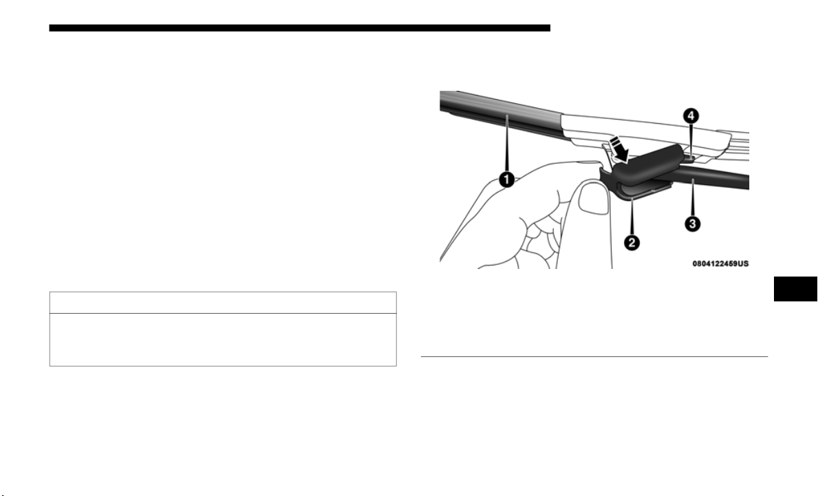
SERVICING AND MAINTENANCE 473
The wiper blades and wiper arms should be inspected peri-
odically, not just when wiper performance problems are
experien
ced. This inspection should include the following
points:
• Wear or uneven edges
• Foreign m
aterial
• Hardeni
ng or cracking
• Deforma
tion or fatigue
If a wip
er blade or wiper arm is damaged, replace the
affected
wiper arm or blade with a new unit. Do not attempt
to repair a wiper arm or blade that is damaged.
Wiper Blade Removal/Installation
1. Lift the wiper arm to raise the wiper blade off of the glass,
until t
he wiper arm is in the full up position.
Wiper Blade With Release Tab In Locked Position
CAUTION!
Do not allow the wiper arm to spring back against the
gl
ass wit
hout the wiper blade in place or the glass may
be damaged.
1 — Wiper Blade
2 — Cover
3 — Wiper Arm
4 — Release Tab
7

474 SERVICING AND MAINTENANCE
2. To disengage the wiper blade from the wiper arm, raise
the cover, press the release tab on the wiper blade and
while holding the wiper arm with one hand, slide the
wiper blade down towards the base of the wiper arm.
Wiper Blade With Release Tab In Unlocked Position
3. With the wiper blade disengaged, remove the wiper
blade from the wiper arm.
4. Gently lower the wiper arm onto the glass.
Install
ing The Front Wipers
1. Lift the wiper arm off of the glass, until the wiper arm is
in the
full up position.
2. Position the wiper blade near the hook on the tip of the
wiper ar
m.
3. Insert the hook on the tip of the arm through the opening
in the
wiper blade.
4. Slide the wiper blade up into the hook on the wiper arm,
latch e
ngagement will be accompanied by an audible
click then close the cover.
5. Gently lower the wiper blade onto the glass.
1 — Wiper Blade
2 — Wiper Arm J Hook
3 — J Hook Retainer
4 — Cover
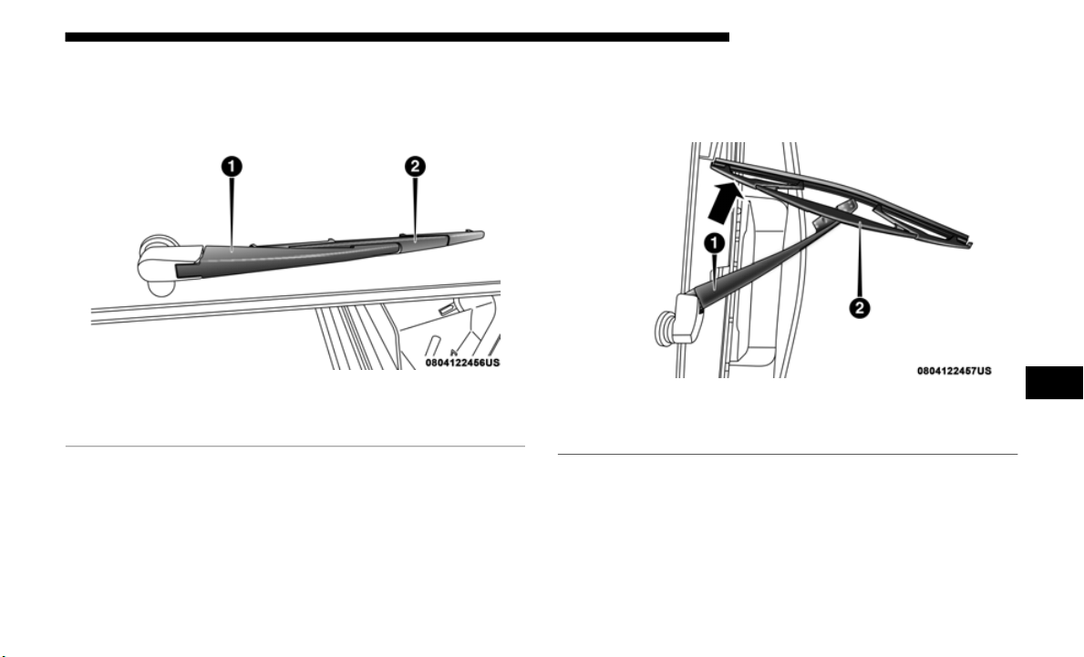
SERVICING AND MAINTENANCE 475
Rear Wiper Blade Removal/Installation
1. Open tailgate to access the wiper arm.
Rear Wi
per Assembly
2. Lift wiper arm off of the glass and rotate wiper blade
outward
to disengage the wiper blade from the wiper
arm.
Wiper Blade And Wiper Arm
1 — Wiper Arm
2 — Wiper Blade
1 — Wiper Arm
2 — Wiper Blade
7

476 SERVICING AND MAINTENANCE
(Continued)
3. Gently set the arm on the glass.
Wiper Blade Removed From Wiper Arm
Installing The Rear Wiper
1. Lift the wiper arm off of the glass.
2. Inser
t the wiper blade pivot pin into the opening on the
end of the wiper arm and rotate the wiper in to place.
3. Place with wiper on the glass and close the tail gate.
Exhaust System
The best protection against carbon monoxide entry into the
vehicle body is a properly maintained engine exhaust
system.
If you notice a change in the sound of the exhaust system; or
if the e
xhaust fumes can be detected inside the vehicle; or
when the underside or rear of the vehicle is damaged; have
an authorized technician inspect the complete exhaust
system and adjacent body areas for broken, damaged, dete
-
riorated, or mispositioned parts. Open seams or loose
connecti
ons could permit exhaust fumes to seep into the
passenger compartment. In addition, have the exhaust
system inspected each time the vehicle is raised for lubrica
-
tion or oil change. Replace as required.
1 — Wiper Blade Pivot Pin
2 — Wiper Arm Receptacle
WARNING!
• Exhaust gases can injure or kill. They contain carbon
monoxide
(CO), which is colorless and odorless.
Breathing it can make you unconscious and can eventu
-
ally poison you. To avoid breathing CO, refer to “Safety
Tips” in
“Safety” for further information.

SERVICING AND MAINTENANCE 477
Under normal operating conditions, the catalytic converter
will not require maintenance. However, it is important to
keep the engine properly tuned to assure proper catalyst
operation and prevent possible catalyst damage.
NOTE:
Intentional tampering with emissions control systems can
r
esult
in civil penalties being assessed against you.
In unusual situations involving grossly malfunctioning
engine o
peration, a scorching odor may suggest severe and
abnormal catalyst overheating. If this occurs, stop the
vehicle, turn off the engine and allow it to cool. Service,
including a tune-up to manufacturer's specifications, should
be obtained immediately.
To minimize the possibility of catalytic converter damage:
• D
o not interrupt the ignition when the transmission is in
gear an
d the vehicle is in motion.
• Do not try to start the vehicle by pushing or towing the
vehicl
e.
• Do not idle the engine with any ignition components
discon
nected or removed, such as when diagnostic testing,
or for prolonged periods during very rough idle or
malfunctioning operating conditions.
• A hot exhaust system can start a fire if you park over
materi
als that can burn. Such materials might be grass
or leaves coming into contact with your exhaust system.
Do not park or operate your vehicle in areas where your
exhaust system can contact anything that can burn.
CAUTION!
• The catalytic converter requires the use of unleaded
fuel on
ly. Leaded gasoline will destroy the effective-
ness of the catalyst as an emissions control device and
m
ay seri
ously reduce engine performance and cause
serious damage to the engine.
• Damage to the catalytic converter can result if your
vehicle
is not kept in proper operating condition. In the
event of engine malfunction, particularly involving
engine misfire or other apparent loss of performance,
have your vehicle serviced promptly. Continued opera
-
tion of your vehicle with a severe malfunction could
cause t
he converter to overheat, resulting in possible
damage to the converter and vehicle.
WARNING! (Continued)
7

478 SERVICING AND MAINTENANCE
Cooling System
Coolant Checks
Check the engine, battery (if equipped), intercooler (if
equippe
d), and Motor Generator Unit (MGU) (if equipped)
coolant (antifreeze) protection every 12
months (before the
onset o
f freezing weather, where applicable). If the engine,
battery (if equipped), intercooler (if equipped), and MGU (if
equipped) coolant (antifreeze) is dirty or rusty in appear
-
ance, the system should be drained, flushed and refilled with
f
resh O
AT coolant (conforming to MS.90032) by an autho-
rized dealer. Check the front of the A/C condenser (if
e
quippe
d) or radiator for any accumulation of bugs, leaves,
etc. If dirty, clean by gently spraying water from a garden
hose vertically down the face of the A/C condenser (if
equipped) or the back of the radiator core.
Check the engine, battery (if equipped), intercooler (if
equippe
d), and MGU (if equipped) cooling system hoses for
brittle rubber, cracking, tears, cuts, and tightness of the
connection at the coolant recovery bottle and radiator.
Inspect the entire system for leaks. DO NOT REMOVE THE
COOLANT PRESSURE CAP WHEN THE COOLING
SYSTEM IS HOT.
WARNING!
• You or others can be badly burned by hot engine
coolant
(antifreeze) or steam from your radiator. If you
see or hear steam coming from under the hood, do not
open the hood until the radiator has had time to cool.
Never open a cooling system pressure cap when the
radiator or coolant bottle is hot.
• Keep hands, tools, clothing, and jewelry away from the
radiat
or cooling fan when the hood is raised. The fan
starts automatically and may start at any time, whether
the engine is running or not.
• When working near the radiator cooling fan, discon-
nect t
he fan motor lead or turn the ignition to the OFF
mode. Th
e fan is temperature controlled and can start at
any time the ignition is in the ON mode.

SERVICING AND MAINTENANCE 479
Cooling System — Drain, Flush And Refill
NOTE:
Some vehicles require special tools to add coolant properly.
Failure
to fill these systems properly could lead to severe
internal engine damage. If any coolant is needed to be added
to the system please contact an authorized dealer.
If the engine coolant (antifreeze) is dirty or contains visible
sedimen
t, have an authorized dealer clean and flush with
OAT coolant (antifreeze) (conforming to MS.90032).
Refer to the “Maintenance Plan” in this section for the proper
mainten
ance intervals.
Selection Of Coolant
Refer to “Fluids And Lubricants” in “Technical Specifica-
tions” for further information.
NOTE:
• M
ixing of engine coolant (antifreeze) other than specified
Organic
Additive Technology (OAT) engine coolant (anti-
freeze), may result in engine damage and may decrease
c
orrosi
on protection. Organic Additive Technology (OAT)
engine coolant is different and should not be mixed with
Hybrid Organic Additive Technology (HOAT) engine
coolant (antifreeze) or any “globally compatible” coolant
(antifreeze). If a non-OAT engine coolant (antifreeze) is
introduced into the cooling system in an emergency, the
cooling system will need to be drained, flushed, and
refilled with fresh OAT coolant (conforming to MS.90032),
by an authorized dealer as soon as possible.
• Do not use water alone or alcohol-based engine coolant
(antif
reeze) products. Do not use additional rust inhibitors
or antirust products, as they may not be compatible with
the radiator engine coolant and may plug the radiator.
• This vehicle has not been designed for use with propylene
glycol-b
ased engine coolant (antifreeze). Use of propylene
glycolbased engine coolant (antifreeze) is not recom
-
mended.
• S
ome vehicles require special tools to add coolant prop-
erly. Fa
ilure to fill these systems properly could lead to
severe
internal engine damage. If any coolant is needed to
be added to the system please contact an authorized
dealer.
7

480 SERVICING AND MAINTENANCE
Adding Coolant
Your vehicle has been built with an improved engine coolant
(OAT co
olant conforming to MS.90032) that allows extended
maintenance intervals. This engine coolant (antifreeze) can
be used up to ten years or 150,000
miles (240,000 km) before
replace
ment. To prevent reducing this extended mainte-
nance period, it is important that you use the same engine
c
oolant
(OAT coolant conforming to MS.90032) throughout
the life of your vehicle.
Please review these recommendations for using Organic
Additiv
e Technology (OAT) engine coolant (antifreeze) that
meets the requirements of FCA Material Standard MS.90032.
When adding engine coolant (antifreeze):
• We recommend using Mopar Antifreeze/Coolant 10 Year/
150,00
0 Mile (240,000 km) Formula OAT (Organic Additive
Technol
ogy) that meets the requirements of FCA Material
Standard MS.90032.
• Mix a minimum solution of 50% OAT engine coolant that
meets
the requirements of FCA Material Standard
MS.90032 and distilled water. Use higher concentrations
(not to exceed 70%) if temperatures below −34°F (−37°C)
are anticipated. Please contact an authorized dealer for
assistance.
• Use only high purity water such as distilled or deionized
water wh
en mixing the water/engine coolant (antifreeze)
solution. The use of lower quality water will reduce the
amount of corrosion protection in the engine cooling
system.
NOTE:
• It is the owner's responsibility to maintain the proper level
of pro
tection against freezing according to the tempera-
tures occurring in the area where the vehicle is operated.
• S
ome vehicles require special tools to add coolant prop-
erly. Fa
ilure to fill these systems properly could lead to
severe
internal engine damage. If any coolant is needed to
be added to the system, please contact a local authorized
dealer.
• Mixing engine coolant (antifreeze) types is not recom-
mended
and can result in cooling system damage. If
HOAT an
d OAT coolant are mixed in an emergency, have
a authorized dealer drain, flush, and refill with OAT
coolant (conforming to MS.90032) as soon as possible.

SERVICING AND MAINTENANCE 481
Cooling System Pressure Cap
The cap must be fully tightened to prevent loss of engine
coolant
(antifreeze), and to ensure that engine coolant (anti-
freeze) will return to the radiator from the coolant expansion
b
ottle/r
ecovery tank if so equipped.
The cap should be inspected and cleaned if there is any accu-
mulation of foreign material on the sealing surfaces.
Disposal Of Used Coolant
Used ethylene glycol-based coolant (antifreeze) is a regu-
lated substance requiring proper disposal. Check with your
l
ocal a
uthorities to determine the disposal rules for your
community. To prevent ingestion by animals or children, do
not store ethylene glycol-based coolant in open containers or
allow it to remain in puddles on the ground. If ingested by a
child or pet, seek emergency assistance immediately. Clean
up any ground spills immediately.
Coolant Level
The coolant bottle provides a quick visual method for deter-
mining that the coolant level is adequate. With the engine OFF
and col
d, the level of the engine coolant (antifreeze) in the
bottle should be between the ranges indicated on the bottle.
The radiator normally remains completely full, so there is no
need to
remove the radiator/coolant pressure cap unless
checking for engine coolant (antifreeze) freeze point or
replacing coolant. Advise your service attendant of this. As
long as the engine operating temperature is satisfactory, the
coolant bottle need only be checked once a month.
WARNING!
• Do not open hot engine cooling system. Never add
engine
coolant (antifreeze) when the engine is over-
heated. Do not loosen or remove the cap to cool an over-
heated engine. Heat causes pressure to build up in the
c
ooling sys
tem. To prevent scalding or injury, do not
remove the pressure cap while the system is hot or
under pressure.
• Do not use a pressure cap other than the one specified
for your
vehicle. Personal injury or engine damage may
result.
7

482 SERVICING AND MAINTENANCE
When additional engine coolant (antifreeze) is needed to
maintain the proper level, only OAT coolant that meets the
requirements of FCA Material Standard MS.90032 should be
added to the coolant bottle. Do not overfill.
Engine Coolant Level — 2.0L
With the engine OFF and cold, the level of the engine coolant
should be within the OK range between the ADD and FULL
range on the dipstick.
1. Remove the cap with level dipstick from the engine
coolan
t bottle.
2. C
lean off the coolant from the dipstick.
3
. Rest
the cap on the opening of the coolant bottle without
tighten
ing the cap.
4. Remove the cap with dipstick and check the coolant level
on the
dipstick.
The radiator normally remains completely full, so there is no
need to
remove the radiator/coolant pressure cap unless
checking for engine coolant (antifreeze) freeze point or
replacing coolant. Advise your service attendant of this. As
long as the engine operating temperature is satisfactory, the
coolant bottle need only be checked once a month.
When additional engine coolant (antifreeze) is needed to
maintai
n the proper level, only OAT coolant that meets the
requirements of FCA Material Standard MS.90032 should be
added to the coolant bottle. Do not overfill.
WARNING!
• Do not open hot engine cooling system. Never add
engine
coolant (antifreeze) when the engine is over-
heated. Do not loosen or remove the cap to cool an over-
heated engine. Heat causes pressure to build up in the
c
ooling sys
tem. To prevent scalding or injury, do not
remove the pressure cap while the system is hot or
under pressure.
• Do not use a pressure cap other than the one specified
for your
vehicle. Personal injury or engine damage may
result.

SERVICING AND MAINTENANCE 483
Points To Remember
NOTE:
When the vehicle is stopped after a few miles/kilometers of
operati
on, you may observe vapor coming from the front of
the engine compartment. This is normally a result of mois
-
ture from rain, snow, or high humidity accumulating on the
radiato
r and being vaporized when the thermostat opens,
allowing hot engine coolant (antifreeze) to enter the radiator.
If an examination of your engine compartment shows no
evidenc
e of radiator or hose leaks, the vehicle may be safely
driven. The vapor will soon dissipate.
• Do not overfill the coolant expansion bottle.
• Check t
he coolant freeze point in the radiator and in the
coolan
t expansion bottle. If engine coolant (antifreeze)
needs to be added, the contents of the coolant expansion
bottle must also be protected against freezing.
• If frequent engine coolant (antifreeze) additions are
requir
ed, the cooling system should be pressure tested for
leaks.
• Maintain engine coolant (antifreeze) concentration at a
minimu
m of 50% OAT coolant (conforming to MS.90032)
and distilled water for proper corrosion protection of your
engine which contains aluminum components.
• Make sure that the coolant expansion bottle overflow
hoses
are not kinked or obstructed.
• Keep the front of the radiator clean. If your vehicle is
equipp
ed with air conditioning, keep the front of the
condenser clean.
• Do not change the thermostat for Summer or Winter oper-
ation.
If replacement is ever necessary, install ONLY the
correct
type thermostat. Other designs may result in unsat-
isfactory engine coolant (antifreeze) performance, poor
ga
s mile
age, and increased emissions.
7

484 SERVICING AND MAINTENANCE
(Continued)
Brake System
In order to assure brake system performance, all brake
system components should be inspected periodically. Refer
to the “Maintenance Plan” in this section for the proper
maintenance intervals.
Fluid Level Check — Brake Master Cylinder
The fluid level of the master cylinder should be checked when-
ever the vehicle is serviced, or immediately if the brake system
warning
light is on. If necessary, add fluid to bring level within
the designated marks on the side of the reservoir of the brake
master cylinder. Be sure to clean the top of the master cylinder
area before removing cap. With disc brakes, fluid level can be
expected to fall as the brake pads wear. Brake fluid level
should be checked when pads are replaced. If the brake fluid is
abnormally low, check the system for leaks.
Refer to “Fluids And Lubricants” in “Technical Specifica-
tions” for further information.
WARNING!
Riding the brakes can lead to brake failure and possibly
a collis
ion. Driving with your foot resting or riding on
the brake pedal can result in abnormally high brake
temperatures, excessive lining wear, and possible brake
damage. You would not have your full braking capacity
in an emergency.
WARNING!
• Use only manufacturer's recommended brake fluid.
Refer
to “Fluids And Lubricants” in “Technical Speci-
fications” for further information. Using the wrong
t
ype of b
rake fluid can severely damage your brake
system and/or impair its performance. The proper type
of brake fluid for your vehicle is also identified on the
original factory installed hydraulic master cylinder
reservoir.
• To avoid contamination from foreign matter or mois-
ture,
use only new brake fluid or fluid that has been in
a tightl
y closed container. Keep the master cylinder
reservoir cap secured at all times. Brake fluid in a open
container absorbs moisture from the air resulting in a
lower boiling point. This may cause it to boil unexpect
-
edly during hard or prolonged braking, resulting in
sudden
brake failure. This could result in a collision.
• Overfilling the brake fluid reservoir can result in
spilli
ng brake fluid on hot engine parts, causing the
brake fluid to catch fire. Brake fluid can also damage
painted and vinyl surfaces, care should be taken to
avoid its contact with these surfaces.

SERVICING AND MAINTENANCE 485
Front/Rear Axle Fluid
For normal service, periodic fluid level checks are not
required. When the vehicle is serviced for other reasons the
exterior surfaces of the axle assembly should be inspected. If
gear oil leakage is suspected inspect the fluid level. Refer to
“Fluids And Lubricants” in “Technical Specifications” for
further information.
Fluid Level Check
Lubricant should be approximately 1/8 inch (3 mm) below
the bot
tom edge of the oil fill hole.
NOTE:
Make sure that the vehicle is level and supported by the axles
Adding Fluid
Add lubricant only at the fill hole and only to the level spec-
ified above.
Selection Of Lubricant
Use only the manufacturer's recommended fluid. Refer to
“
Fluids
And Lubricants” in “Technical Specifications” for
further information.
Transfer Case
Selection Of Lubricant
Use only the manufacturer's recommended fluid. Refer to
“Fluids
And Lubricants” in “Technical Specifications” for
further information.
• Do not allow petroleum based fluid to contaminate the
brake
fluid. Brake seal components could be damaged,
causing partial or complete brake failure. This could
result in a collision.
WARNING! (Continued)
7
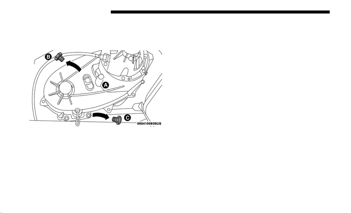
486 SERVICING AND MAINTENANCE
Fluid Level Check
The fluid level should be to the bottom edge of the fill hole
(A) when
the vehicle is in a level position.
Transfer Case
Drain And Refill
Refer to the “Maintenance Plan” in this section for the proper
maintena
nce intervals.
Manual Transmission
Selection Of Lubricant
Use only manufacturer's recommended manual transmis-
sion fluid. Refer to “Fluids And Lubricants” in “Technical
Specific
ations” for further information.
Fluid Level Check
Check the fluid level by removing the fill plug. The fluid
l
evel sh
ould be between the bottom of the fill hole and a
point not more than 3/16 of an inch (4.76
mm) below the
bottom o
f the hole.
Add fluid, if necessary, to maintain the proper level.
Frequency Of Fluid Change
Under normal operating conditions, the fluid installed at the
f
actory wi
ll give satisfactory lubrication for the life of the
vehicle. If the fluid becomes contaminated with water, it
should be changed immediately. Otherwise, change the fluid
as recommended in the Maintenance Plan. Refer to the
“Maintenance Plan” for the proper maintenance intervals.

SERVICING AND MAINTENANCE 487
Automatic Transmission
Selection Of Lubricant
It is important to use the proper transmission fluid to ensure
optimum
transmission performance and life. Use only the
manufacturer's specified transmission fluid. Refer to “Fluids
And Lubricants” in “Technical Specifications” for fluid spec
-
ifications. It is important to maintain the transmission fluid
a
t the
correct level using the recommended fluid.
NOTE:
No chemical flushes should be used in any transmission;
o
nly the
approved lubricant should be used.
Special Additives
The manufacturer strongly recommends against using any
special
additives in the transmission. Automatic Transmis-
sion Fluid (ATF) is an engineered product and its perfor-
mance may be impaired by supplemental additives.
T
herefo
re, do not add any fluid additives to the transmis-
sion. Avoid using transmission sealers as they may
a
dverse
ly affect seals.
CAUTION!
Using a transmission fluid other than the manufacturer’s
recomme
nded fluid may cause deterioration in transmission
shift quality and/or torque converter shudder. Refer to “Fluids
And Lubricants” in “Technical Specifications” for fluid
specifications.
CAUTION!
Do not use chemical flushes in your transmission as the
chemica
ls can damage your transmission components. Such
damage is not covered by the New Vehicle Limited Warranty.
7

488 SERVICING AND MAINTENANCE
Fluid Level Check
The fluid level is preset at the factory and does not require
adjustm
ent under normal operating conditions. Routine
fluid level checks are not required; therefore the transmis
-
sion has no dipstick. An authorized dealer can check your
transmi
ssion fluid level using special service tools. If you
notice fluid leakage or transmission malfunction, visit an
authorized dealer immediately to have the transmission
fluid level checked. Operating the vehicle with an improper
fluid level can cause severe transmission damage.
Fluid And Filter Changes
Under normal operating conditions, the fluid installed at the factory
will pr
ovide satisfactory lubrication for the life of the vehicle.
Routine fluid and filter changes are not required. However,
c
h
ange t
he fluid and filter if the fluid becomes contaminated
(with water, etc.), or if the transmission is disassembled for
any reason.
RAISING THE VEHICLE
In the case where it is necessary to raise the vehicle, go to an
authorized dealer or service station.
TIRES
Tire Safety Information
Tire safety information will cover aspects of the following infor-
mation: Tire Markings, Tire Identification Numbers, Tire Termi-
nology and Definitions, Tire Pressures, and Tire Loading.
CAUTION!
If a transmission fluid leak occurs, visit an authorized
d
ealer
immediately. Severe transmission damage may
occur. An authorized dealer has the proper tools to adjust
the fluid level accurately.
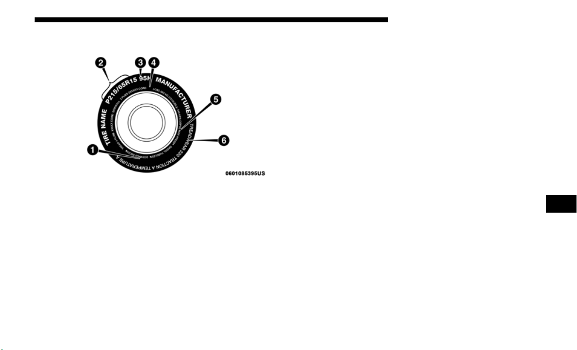
SERVICING AND MAINTENANCE 489
Tire Markings
Tire Markings
NOTE:
• P (Passenger) — Metric tire sizing is based on U.S. design
standar
ds. P-Metric tires have the letter “P” molded into
the sidewall preceding the size designation. Example:
P215/65R15 95H.
• European — Metric tire sizing is based on European
design s
tandards. Tires designed to this standard have the
tire size molded into the sidewall beginning with the
section width. The letter "P" is absent from this tire size
designation. Example: 215/65R15 96H.
• LT (Light Truck) — Metric tire sizing is based on U.S.
design s
tandards. The size designation for LT-Metric tires
is the same as for P-Metric tires except for the letters “LT”
that are molded into the sidewall preceding the size desig
-
nation. Example: LT235/85R16.
• T
emporary spare tires are designed for temporary emer-
gency use
only. Temporary high pressure compact spare
tires ha
ve the letter “T” or “S” molded into the sidewall
preceding the size designation. Example: T145/80D18
103M.
• High flotation tire sizing is based on U.S. design standards
and it
begins with the tire diameter molded into the side-
wall. Example: 31x10.5 R15 LT.
1 — U.S. DOT Safety
Standards Code (TIN)
4 — Maximum Load
2 — Size Designation 5 — Maximum Pressure
3 — Service Description 6 — Treadwear, Traction
and Temp
erature Grades
7

490 SERVICING AND MAINTENANCE
Tire Sizing Chart
EXAMPLE:
Example Size Designation: P215/65R15XL 95H, 215/65R15 96H, LT235/85R16C, T145/80D18 103M, 31x10.5 R15 LT
P
= Passenger car tire size based on U.S. design standards, or
"....b
lank...." = Passe
nger car tire based on European design standards, or
LT = Light truck tire based on U.S. design standards, or
T or S =
Temporary spare tire or
31 = Over
all diameter in inches (in)
215, 2
35, 145 = Secti
on width in millimeters (mm)
65, 85, 80 = Aspect ratio in percent (%)
• Ratio
of section height to section width of tire, or
10.5 = S
ection width in inches (in)
R = Construction code
•
"R" me
ans radial construction, or
• "D" me
ans diagonal or bias construction
15, 16
, 18 = Rim diameter in inches (in)
Service
Description:
95
= Load Index
• A nume
rical code associated with the maximum load a tire can carry

SERVICING AND MAINTENANCE 491
H = Speed Symbol
• A symbol indicating the range of speeds at which a tire can carry a load corresponding to its load index under certain oper-
ating c
onditions
• T
he maximum speed corresponding to the speed symbol should only be achieved under specified operating conditions
(i.e.,
tire pressure, vehicle loading, road conditions, and posted speed limits)
Load Identification:
Absence of the following load identification symbols on the sidewall of the tire indicates a Standard Load (SL) tire:
• X
L = Extra load (or reinforced) tire, or
• LL = Light load tire or
• C,
D,
E, F, G = Load
range associated with the maximum load a tire can carry at a specified pressure
Maximum Load – Maxi
mum load indicates the maximum load this tire is designed to carry
Maximum Pressure – Maxi
mum pressure indicates the maximum permissible cold tire inflation pressure for this tire
EXAMPLE:
7

492 SERVICING AND MAINTENANCE
Tire Identification Number (TIN)
The TIN may be found on one or both sides of the tire; however, the date code may only be on one side. Tires with white side-
walls will have the full TIN, including the date code, located on the white sidewall side of the tire. Look for the TIN on the
outboar
d side of black sidewall tires as mounted on the vehicle. If the TIN is not found on the outboard side, then you will
find it on the inboard side of the tire.
EXAMPLE:
DOT MA L9 ABCD 0301
DOT = Department of Transportation
• This s
ymbol certifies that the tire is in compliance with the U.S. Department of Transportation tire safety standards and is
approv
ed for highway use
MA = Code representing the tire manufacturing location (two digits)
L9 = Code
representing the tire size (two digits)
ABCD = C
ode used by the tire manufacturer (one to four digits)
03 = Numb
er representing the week in which the tire was manufactured (two digits)
• 03 means the 3rd week
01 = N
umber representing the year in which the tire was manufactured (two digits)
• 01 means the year 2001
• Pri
or to July 2000, tire manufacturers were only required to have one number to represent the year in which the tire was
manufa
ctured. Example: 031 could represent the 3rd week of 1981 or 1991

SERVICING AND MAINTENANCE 493
Tire Terminology And Definitions
Term Definition
B-Pillar
The vehicle B-Pillar is the structural member of the body located behind
t
he fro
nt door.
Cold Tire Inflation Pressure
Cold tire inflation pressure is defined as the tire pressure after the vehicle
has not
been driven for at least three hours, or driven less than 1 mile
(1.6 km)
after sitting for a minimum of three hours. Inflation pressure is
measure
d in units of PSI (pounds per square inch) or kPa (kilopascals).
Maximum Inflation Pressure
The maximum inflation pressure is the maximum permissible cold tire
i
nflati
on pressure for this tire. The maximum inflation pressure is
molded into the sidewall.
Recommended Cold Tire Inflation Pressure
Vehicle manufacturer's recommended cold tire inflation pressure as
s
hown on
the tire placard.
Tire Placard
A label permanently attached to the vehicle describing the vehicle’s
l
oading
capacity, the original equipment tire sizes and the recommended
cold tire inflation pressures.
7

494 SERVICING AND MAINTENANCE
Tire Loading And Tire Pressure
NOTE:
The proper cold tire inflation pressure is listed on the
driver’s
side B-Pillar or the rear edge of the driver's side
door.
Check the inflation pressure of each tire, including the spare
tire (if
equipped), at least monthly and inflate to the recom-
mended pressure for your vehicle.
Example Tire Placard Location (Door)
Example Tire Placard Location (B-Pillar)
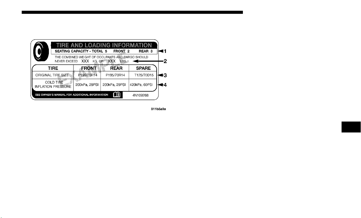
SERVICING AND MAINTENANCE 495
Tire And Loading Information Placard
Tire And Loading Information Placard
This placard tells you important information about the:
1. Number of people that can be carried in the vehicle.
2. Tota
l weight your vehicle can carry.
3. Tire
size designed for your vehicle.
4. Cold
tire inflation pressures for the front, rear, and spare
tires.
L
oading
The vehicle maximum load on the tire must not exceed the
load ca
rrying capacity of the tire on your vehicle. You will
not exceed the tire's load carrying capacity if you adhere to
the loading conditions, tire size, and cold tire inflation pres
-
sures specified on the Tire and Loading Information placard
i
n “Veh
icle Loading” in the “Starting And Operating”
section of this manual.
NOTE:
Under a maximum loaded vehicle condition, gross axle
weight ra
tings (GAWRs) for the front and rear axles must not
be exceeded.
For further information on GAWRs, vehicle loading, and
trailer
towing, refer to “Vehicle Loading” in the “Starting
And Operating” section of this manual.
To determine the maximum loading conditions of your
vehicle
, locate the statement “The combined weight of occu-
pants and cargo should never exceed XXX kg or XXX lbs” on
t
he Tir
e and Loading Information placard. The combined
weight of occupants, cargo/luggage and trailer tongue
weight (if applicable) should never exceed the weight refer
-
enced here.
7

496 SERVICING AND MAINTENANCE
Steps For Determining Correct Load Limit—
(1) Locate the statement “The combined weight of occu-
pants and cargo should never exceed XXX kg or XXX lbs.”
on your
vehicle's placard.
(2) Determine the combined weight of the driver and
passeng
ers that will be riding in your vehicle.
(3) Subtract the combined weight of the driver and
passeng
ers from XXX kg or XXX lbs.
(4) The resulting figure equals the available amount of
cargo a
nd luggage load capacity. For example, if “XXX”
amount equals 1400 lbs. and there will be five 150 lb
passengers in your vehicle, the amount of available cargo
and luggage load capacity is 650 lbs. (1400-750 (5x150) =
650 lbs.)
(5) Determine the combined weight of luggage and cargo
being l
oaded on the vehicle. That weight may not safely
exceed the available cargo and luggage load capacity
calculated in Step 4.
(6) If your vehicle will be towing a trailer, load from your
trailer
will be transferred to your vehicle. Consult this
manual to determine how this reduces the available cargo
and luggage load capacity of your vehicle.
Metric Example For Load Limit
For example, if “XXX” amount equals 635 kg and there will
be five 68 kg passengers in your vehicle, the amount of avail-
able cargo and luggage load capacity is 295 kg (635-340
(
5x68)
= 295 kg) as shown in step 4.
NOTE:
• I
f your vehicle will be towing a trailer, load from your
traile
r will be transferred to your vehicle. The following
table shows examples on how to calculate total load,
cargo/luggage, and towing capacities of your vehicle with
varying seating configurations and number and size of
occupants. This table is for illustration purposes only and
may not be accurate for the seating and load carry capacity
of your vehicle.
• For the following example, the combined weight of occu-
pants
and cargo should never exceed 865 lbs (392 kg).
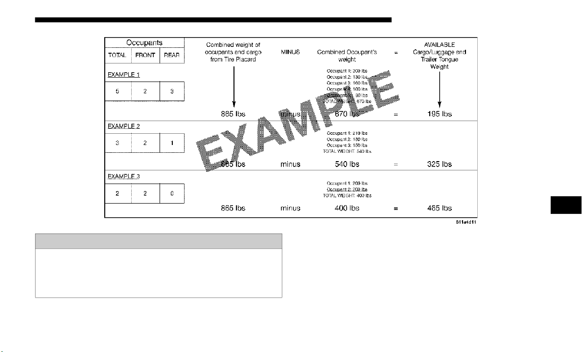
SERVICING AND MAINTENANCE 497
WARNING!
Overloading of your tires is dangerous. Overloading can
cause t
ire failure, affect vehicle handling, and increase
your stopping distance. Use tires of the recommended
load capacity for your vehicle. Never overload them.
7

498 SERVICING AND MAINTENANCE
(Continued)
Tires — General Information
Tire Pressure
Proper tire inflation pressure is essential to the safe and satis-
factory operation of your vehicle. Four primary areas are
affecte
d by improper tire pressure:
• Safety and Vehicle Stability
• Econom
y
• Tread
Wear
• Ride C
omfort
Safety
B
oth under-inflation and over-inflation affect the stability of
the veh
icle and can produce a feeling of sluggish response or
over responsiveness in the steering.
NOTE:
• Unequal tire pressures from side to side may cause erratic
and un
predictable steering response.
• Unequal tire pressure from side to side may cause the
vehicl
e to drift left or right.
WARNING!
• Improperly inflated tires are dangerous and can cause
collisi
ons.
• Underinflation increases tire flexing and can result in
overheat
ing and tire failure.
• Overinflation reduces a tire's ability to cushion shock.
Object
s on the road and chuckholes can cause damage
that result in tire failure.
• Overinflated or underinflated tires can affect vehicle
handling and can fail suddenly, resulting in loss of
vehicle control.
• Unequal tire pressures can cause steering problems.
You could lose control of your vehicle.
• Unequal tire pressures from one side of the vehicle to
the oth
er can cause the vehicle to drift to the right or
left.
• Always drive with each tire inflated to the recom-
mended
cold tire inflation pressure.
WARNING! (Continued)

SERVICING AND MAINTENANCE 499
Fuel Economy
Underinflated tires will increase tire rolling resistance
resulti
ng in higher fuel consumption.
Tread Wear
Improper cold tire inflation pressures can cause abnormal
we
ar pat
terns and reduced tread life, resulting in the need
for earlier tire replacement.
Ride Comfort And Vehicle Stability
Proper tire inflation contributes to a comfortable ride.
Over-in
flation produces a jarring and uncomfortable ride.
Tire Inflation Pressures
The proper cold tire inflation pressure is listed on the driver's
side B-
Pillar or rear edge of the driver's side door.
At least once a month:
• C
heck and adjust tire pressure with a good quality
pocket-
type pressure gauge. Do not make a visual judge-
ment when determining proper inflation. Tires may look
p
roperl
y inflated even when they are under-inflated.
• Inspect tires for signs of tire wear or visible damage.
Inflat
ion pressures specified on the placard are always “cold
tire in
flation pressure”. Cold tire inflation pressure is
defined as the tire pressure after the vehicle has not been
driven for at least three hours, or driven less than 1
mile
(1.6 km)
after sitting for a minimum of three hours. The cold
tire in
flation pressure must not exceed the maximum infla-
tion pressure molded into the tire sidewall.
Check tire pressures more often if subject to a wide range of
o
utdoor
temperatures, as tire pressures vary with tempera-
ture changes.
Tire pressures change by approximately 1 psi (7 kPa) per 12°F
(
7°C) o
f air temperature change. Keep this in mind when
checking tire pressure inside a garage, especially in the Winter.
CAUTION!
After inspecting or adjusting the tire pressure, always
reinsta
ll the valve stem cap. This will prevent moisture
and dirt from entering the valve stem, which could
damage the valve stem.
7

500 SERVICING AND MAINTENANCE
Example: If garage temperature = 68°F (20°C) and the outside
temperature = 32°F (0°C) then the cold tire inflation pressure should
be increased by 3 psi (21 kPa), which equals 1 psi (7 kPa) for every
12°F (7°C) for this outside temperature condition.
Tire pressure may increase from 2 to 6 psi (13 to 40 kPa)
during o
peration. DO NOT reduce this normal pressure
build up or your tire pressure will be too low.
Tire Pressures For High Speed Operation
The manufacturer advocates driving at safe speeds and
within p
osted speed limits. Where speed limits or conditions
are such that the vehicle can be driven at high speeds, main
-
taining correct tire inflation pressure is very important.
Increas
ed tire pressure and reduced vehicle loading may be
required for high-speed vehicle operation. Refer to an autho
-
rized tire dealer or original equipment vehicle dealer for
recomme
nded safe operating speeds, loading and cold tire
inflation pressures.
Radial Ply Tires
Tire Repair
If your tire becomes damaged, it may be repaired if it meets
the fol
lowing criteria:
• The tire has not been driven on when flat.
• The da
mage is only on the tread section of your tire (side-
wall da
mage is not repairable).
• T
he puncture is no greater than a ¼ of an inch (6 mm).
Co
nsult an authorized tire dealer for tire repairs and addi-
tional information.
Damaged Run Flat tires, or Run Flat tires that have experi-
enced a loss of pressure should be replaced immediately
wi
th ano
ther Run Flat tire of identical size and service
description (Load Index and Speed Symbol). Replace the tire
pressure sensor as well as it is not designed to be reused.
WARNING!
High speed driving with your vehicle under maximum
load is
dangerous. The added strain on your tires could
cause them to fail. You could have a serious collision. Do
not drive a vehicle loaded to the maximum capacity at
continuous speeds above 75
mph (120 km/h).
WARNING!
Combining radial ply tires with other types of tires on
your vehic
le will cause your vehicle to handle poorly.
The instability could cause a collision. Always use radial
ply tires in sets of four. Never combine them with other
types of tires.

SERVICING AND MAINTENANCE 501
Run Flat Tires — If Equipped
Run Flat tires allow you the capability to drive 50 miles
(80 km) a
t 50 mph (80 km/h) after a rapid loss of inflation
pressur
e. This rapid loss of inflation is referred to as the Run
Flat mode. A Run Flat mode occurs when the tire inflation
pressure is of/or below 14 psi (96 kPa). Once a Run Flat tire
reaches the run flat mode it has limited driving capabilities
and needs to be replaced immediately. A Run Flat tire is not
repairable. When a run flat tire is changed after driving with
underinflated tire condition, please replace the TPM sensor
as it is not designed to be reused when driven under run flat
mode (14 psi (96 kPa)) condition.
NOTE:
TPM Sensor must be replaced after driving the vehicle on a
f
lat ti
re condition.
It is not recommended driving a vehicle loaded at full
capacit
y or to tow a trailer while a tire is in the run flat mode.
See the tire pressure monitoring section for more informa-
tion.
Tire Spinning
When stuck in mud, sand, snow, or ice conditions, do not
s
pin you
r vehicle's wheels above 30 mph (48 km/h) or for
longer t
han 30 seconds continuously without stopping.
Refer to “Freeing A Stuck Vehicle” in “In Case Of Emer-
gency” for further information.
WARNING!
Fast spinning tires can be dangerous. Forces generated
by exces
sive wheel speeds may cause tire damage or
failure. A tire could explode and injure someone. Do not
spin your vehicle's wheels faster than 30
mph (48 km/h)
for more
than 30 seconds continuously when you are
stuck, and do not let anyone near a spinning wheel, no
matter what the speed.
7
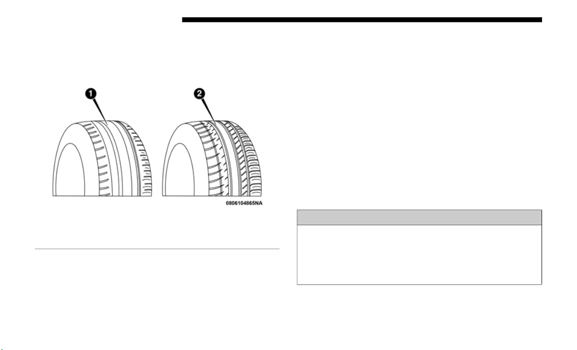
502 SERVICING AND MAINTENANCE
Tread Wear Indicators
Tread wear indicators are in the original equipment tires to
help you
in determining when your tires should be replaced.
Tire Tread
These indicators are molded into the bottom of the tread
grooves.
They will appear as bands when the tread depth
becomes a 1/16 of an inch (1.6
mm). When the tread is worn
to the t
read wear indicators, the tire should be replaced.
Refer to “Replacement Tires” in this section for further information.
Life Of Tire
The service life of a tire is dependent upon varying factors
includin
g, but not limited to:
• Driving style.
• Tire pr
essure - Improper cold tire inflation pressures can
cause u
neven wear patterns to develop across the tire
tread. These abnormal wear patterns will reduce tread life,
resulting in the need for earlier tire replacement.
• Distance driven.
• Perform
ance tires, tires with a speed rating of V or higher,
and Sum
mer tires typically have a reduced tread life. Rota-
tion of these tires per the vehicle scheduled maintenance is
h
ighly rec
ommended.
1 — Worn Tire
2 — New Tire
WARNING!
Tires and the spare tire should be replaced after six
years, re
gardless of the remaining tread. Failure to follow
this warning can result in sudden tire failure. You could
lose control and have a collision resulting in serious
injury or death.

SERVICING AND MAINTENANCE 503
(Continued)
NOTE:
Wheel Valve Stem must be replaced as well when installing
new tire
s due to wear and tear in existing tires.
Keep dismounted tires in a cool, dry place with as little expo-
sure to light as possible. Protect tires from contact with oil,
gr
ease,
and gasoline.
Replacement Tires
The tires on your new vehicle provide a balance of many
charact
eristics. They should be inspected regularly for wear
and correct cold tire inflation pressures. The manufacturer
strongly recommends that you use tires equivalent to the
originals in size, quality and performance when replacement
is needed. Refer to the paragraph on “Tread Wear Indica
-
tors” in this section. Refer to the Tire and Loading Informa-
tion placard or the Vehicle Certification Label for the size
d
esignat
ion of your tire. The Load Index and Speed Symbol
for your tire will be found on the original equipment tire
sidewall.
See the Tire Sizing Chart example found in the “Tire Safety
Informa
tion” section of this manual for more information
relating to the Load Index and Speed Symbol of a tire.
It is recommended to replace the two front tires or two rear
tires a
s a pair. Replacing just one tire can seriously affect
your vehicle’s handling. If you ever replace a wheel, make
sure that the wheel’s specifications match those of the orig
-
inal wheels.
It is recommended you contact an authorized tire dealer or
o
riginal
equipment dealer with any questions you may have
on tire specifications or capability. Failure to use equivalent
replacement tires may adversely affect the safety, handling,
and ride of your vehicle.
WARNING!
• Do not use a tire, wheel size, load rating, or speed rating
other
than that specified for your vehicle. Some combina-
tions of unapproved tires and wheels may change
s
uspens
ion dimensions and performance characteristics,
resulting in changes to steering, handling, and braking of
your vehicle. This can cause unpredictable handling and
stress to steering and suspension components. You could
lose control and have a collision resulting in serious
injury or death. Use only the tire and wheel sizes with
load ratings approved for your vehicle.
7

504 SERVICING AND MAINTENANCE
Tire Types
All Season Tires — If Equipped
All Season tires provide traction for all seasons (Spring,
Summer,
Fall, and Winter). Traction levels may vary
between different all season tires. All season tires can be
identified by the M+S, M&S, M/S or MS designation on the
tire sidewall. Use all season tires only in sets of four; failure
to do so may adversely affect the safety and handling of your
vehicle.
Summer Or Three Season Tires — If Equipped
Summer tires provide traction in both wet and dry condi-
tions, and are not intended to be driven in snow or on ice. If
yo
ur veh
icle is equipped with Summer tires, be aware these
tires are not designed for Winter or cold driving conditions.
Install Winter tires on your vehicle when ambient tempera
-
tures are less than 40°F (5°C) or if roads are covered with ice
o
r snow.
For more information, contact an authorized dealer.
Summer tires do not contain the all season designation or
mountai
n/snowflake symbol on the tire sidewall. Use
Summer tires only in sets of four; failure to do so may
adversely affect the safety and handling of your vehicle.
• Never use a tire with a smaller load index or capacity,
other t
han what was originally equipped on your
vehicle. Using a tire with a smaller load index could
result in tire overloading and failure. You could lose
control and have a collision.
• Failure to equip your vehicle with tires having
adequa
te speed capability can result in sudden tire
failure and loss of vehicle control.
CAUTION!
Replacing original tires with tires of a different size may
result
in false speedometer and odometer readings.
WARNING! (Continued)
WARNING!
Do not use Summer tires in snow/ice conditions. You
could los
e vehicle control, resulting in severe injury or
death. Driving too fast for conditions also creates the
possibility of loss of vehicle control.

SERVICING AND MAINTENANCE 505
Snow Tires
Some areas of the country require the use of snow tires
during th
e Winter. Snow tires can be identified by a “moun-
tain/snowflake” symbol on the tire sidewall.
If you need snow tires, select tires equivalent in size
and type to the original equipment tires. Use snow
t
ires on
ly in sets of four; failure to do so may
adversely affect the safety and handling of your vehicle.
Snow tires generally have lower speed ratings than what was
originall
y equipped with your vehicle and should not be
operated at sustained speeds over 75
mph (120 km/h). For
speeds a
bove 75 mph (120 km/h) refer to original equipment
or an au
thorized tire dealer for recommended safe operating
speeds, loading and cold tire inflation pressures.
While studded tires improve performance on ice, skid and
traction
capability on wet or dry surfaces may be poorer than
that of non-studded tires. Some states prohibit studded tires;
therefore, local laws should be checked before using these
tire types.
Spare Tires — If Equipped
NOTE:
For vehicles equipped with Tire Service Kit instead of a spare
tire, pl
ease refer to “Tire Service Kit” in “In Case Of Emer-
gency” for further information.
Refer to the “Towing Requirements - Tires” in “Starting And
O
peratin
g” for restrictions when towing with a spare tire
designated for temporary emergency use.
Spare Tire Matching Original Equipped Tire And Wheel
— If Equipped
Your vehicle may be equipped with a spare tire and wheel
equivale
nt in look and function to the original equipment
tire and wheel found on the front or rear axle of your vehicle.
This spare tire may be used in the tire rotation for your
vehicle. If your vehicle has this option, refer to an authorized
tire dealer for the recommended tire rotation pattern.
CAUTION!
Because of the reduced ground clearance, do not take
your vehicl
e through an automatic car wash with a
compact or limited use temporary spare installed.
Damage to the vehicle may result.
7

506 SERVICING AND MAINTENANCE
Compact Spare Tire — If Equipped
The compact spare is for temporary emergency use only.
You can
identify if your vehicle is equipped with a compact
spare by looking at the spare tire description on the Tire and
Loading Information Placard located on the driver’s side
door opening or on the sidewall of the tire. Compact spare
tire descriptions begin with the letter “T” or “S” preceding
the size designation. Example: T145/80D18 103M.
T, S = Temporary Spare Tire
Since this tire has limited tread life, the original equipment
tire sh
ould be repaired (or replaced) and reinstalled on your
vehicle at the first opportunity.
Do not install a wheel cover or attempt to mount a conven-
tional tire on the compact spare wheel, since the wheel is
designed
specifically for the compact spare tire. Do not
install more than one compact spare tire and wheel on the
vehicle at any given time.
Full Size Spare — If Equipped
The full size spare is for temporary emergency use only. This
tire ma
y look like the originally equipped tire on the front or
rear axle of your vehicle, but it is not. This spare tire may
have limited tread life. When the tread is worn to the tread
wear indicators, the temporary use full size spare tire needs
to be replaced. Since it is not the same as your original equip
-
ment tire, replace (or repair) the original equipment tire and
r
einsta
ll on the vehicle at the first opportunity.
WARNING!
Compact and collapsible spares are for temporary
emergenc
y use only. With these spares, do not drive
more than 50
mph (80 km/h). Temporary use spares have
limited
tread life. When the tread is worn to the tread
wear indicators, the temporary use spare tire needs to be
replaced. Be sure to follow the warnings, which apply to
your spare. Failure to do so could result in spare tire
failure and loss of vehicle control.

SERVICING AND MAINTENANCE 507
Limited Use Spare — If Equipped
The limited use spare tire is for temporary emergency use
only. Th
is tire is identified by a label located on the limited
use spare wheel. This label contains the driving limitations
for this spare. This tire may look like the original equipped
tire on the front or rear axle of your vehicle, but it is not.
Installation of this limited use spare tire affects vehicle
handling. Since it is not the same as your original equipment
tire, replace (or repair) the original equipment tire and rein
-
stall on the vehicle at the first opportunity.
Wheel And Wheel Trim Care
All wheels and wheel trim, especially aluminum and chrome
plated wheels, should be cleaned regularly using mild
(neutral Ph) soap and water to maintain their luster and to
prevent corrosion. Wash wheels with the same soap solution
recommended for the body of the vehicle and remember to
always wash when the surfaces are not hot to the touch.
Your wheels are susceptible to deterioration caused by salt,
sodium
chloride, magnesium chloride, calcium chloride, etc.,
and other road chemicals used to melt ice or control dust on
dirt roads. Use a soft cloth or sponge and mild soap to wipe
away promptly. Do not use harsh chemicals or a stiff brush.
They can damage the wheel’s protective coating that helps
keep them from corroding and tarnishing.
WARNING!
Limited use spares are for emergency use only.
Install
ation of this limited use spare tire affects vehicle
handling. With this tire, do not drive more than the
speed listed on the limited use spare wheel. Keep
inflated to the cold tire inflation pressures listed on your
Tire and Loading Information Placard located on the
driver’s side B-Pillar or the rear edge of the driver’s side
door. Replace (or repair) the original equipment tire at
the first opportunity and reinstall it on your vehicle.
Failure to do so could result in loss of vehicle control.
CAUTION!
Avoid products or automatic car washes that use acidic
solutions
or strong alkaline additives or harsh brushes.
Many aftermarket wheel cleaners and automatic car
washes may damage the wheel's protective finish. Such
damage is not covered by the New Vehicle Limited
Warranty. Only car wash soap, Mopar Wheel Cleaner or
equivalent is recommended.
7

508 SERVICING AND MAINTENANCE
When cleaning extremely dirty wheels including excessive
brake dust, care must be taken in the selection of tire and
wheel cleaning chemicals and equipment to prevent damage
to the wheels. Mopar Wheel Treatment or Mopar Chrome
Cleaner or their equivalent is recommended or select a
non-abrasive, non-acidic cleaner for aluminum or chrome
wheels.
NOTE:
If you intend parking or storing your vehicle for an extended
p
eriod
after cleaning the wheels with wheel cleaner, drive
your vehicle and apply the brakes to remove the water drop
-
lets from the brake components. This activity will remove the
red rus
t on the brake rotors and prevent vehicle vibration
when braking.
Dark Vapor Chrome, Black Satin Chrome, or Low Gloss
Clear C
oat Wheels
CAUTION!
Do not use scouring pads, steel wool, a bristle brush,
m
etal p
olishes or oven cleaner. These products may
damage the wheel's protective finish. Such damage is not
covered by the New Vehicle Limited Warranty. Only car
wash soap, Mopar Wheel Cleaner or equivalent is
recommended.
CAUTION!
If your vehicle is equipped with these specialty wheels,
DO NOT
USE wheel cleaners, abrasives, or polishing
compounds. They will permanently damage this finish
and such damage is not covered by the New Vehicle
Limited Warranty. HAND WASH ONLY USING MILD
SOAP AND WATER WITH A SOFT CLOTH. Used on a
regular basis; this is all that is required to maintain this
finish.

SERVICING AND MAINTENANCE 509
Tire Chains (Traction Devices)
Use of traction devices require sufficient tire-to-body clear-
ance. Follow these recommendations to guard against
damage.
• T
raction device must be of proper size for the tire, as
recomm
ended by the traction device manufacturer.
• Install on Rear Tires Only.
• Due to
limited clearance, the following traction devices are
recomm
ended:
• Original equipment 255/70R18 and LT285/70R17 tire
sizes
are not chainable.
• The use of S-class snow chains is permitted with the use of
245/75R
17 tires on size 17 x 7.5 ET44.45 wheels.
WARNING!
Using tires of different size and type (M+S, Snow)
between
front and rear axles can cause unpredictable
handling. You could lose control and have a collision.
CAUTION!
To avoid damage to your vehicle or tires, observe the
following
precautions:
• Because of restricted traction device clearance between
tires
and other suspension components, it is important
that only traction devices in good condition are used.
Broken devices can cause serious damage. Stop the
vehicle immediately if noise occurs that could indicate
device breakage. Remove the damaged parts of the
device before further use.
• Install device as tightly as possible and then retighten
after
driving about ½ mile (0.8 km).
• D
o not exceed 30 mph (
48 km/h).
• Drive cautiously and avoid severe turns and large
bumps,
especially with a loaded vehicle.
• Do not drive for a prolonged period on dry pavement.
• Observe
the traction device manufacturer’s instruc-
tions on
the method of installation, operating speed,
and cond
itions for use. Always use the suggested oper-
ating speed of the device manufacturer’s if it is less
t
han 30
mph (48 km/h).
• D
o not use traction devices on a compact spare tire.
7
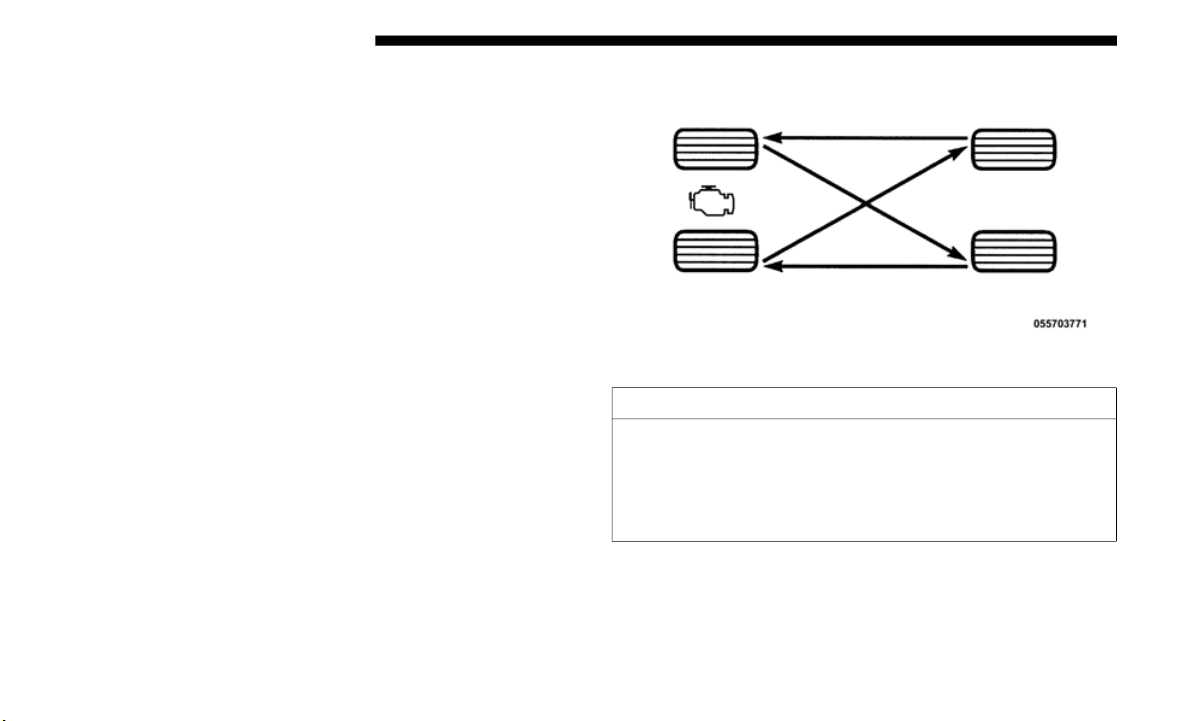
510 SERVICING AND MAINTENANCE
Tire Rotation Recommendations
The tires on the front and rear of your vehicle operate at
different loads and perform different steering, handling, and
braking functions. For these reasons, they wear at unequal
rates.
These effects can be reduced by timely rotation of tires. The
benefit
s of rotation are especially worthwhile with aggres-
sive tread designs such as those on On/Off Road type tires.
R
otatio
n will increase tread life, help to maintain mud, snow,
and wet traction levels, and contribute to a smooth, quiet
ride.
Refer to the “Maintenance Plan” for the proper maintenance
interva
ls. The reasons for any rapid or unusual wear should
be corrected prior to rotation being performed.
The suggested rotation method is the “rearward-cross”
shown in
the following diagram.
Tire Rotation
CAUTION!
Proper operation of four-wheel drive vehicles depends
on tires
of equal size, type and circumference on each
wheel. Any difference in tire size can cause damage to
the transfer case. Tire rotation schedule should be
followed to balance tire wear.

SERVICING AND MAINTENANCE 511
DEPARTMENT OF TRANSPORTATION UNIFORM
TIRE QUALITY GRADES
The following tire grading categories were established by
the Nat
ional Highway Traffic Safety Administration. The
specific grade rating assigned by the tire's manufacturer
in each category is shown on the sidewall of the tires on
your vehicle.
All passenger vehicle tires must conform to Federal safety
require
ments in addition to these grades.
Treadwear
The Treadwear grade is a comparative rating, based on
the wea
r rate of the tire when tested under controlled
conditions on a specified government test course. For
example, a tire graded 150 would wear one and one-half
times as well on the government course as a tire graded
100. The relative performance of tires depends upon the
actual conditions of their use, however, and may depart
significantly from the norm due to variations in driving
habits, service practices, and differences in road charac-
teristics and climate.
Traction Grades
The Traction grades, from highest to lowest, are AA, A, B,
and C.
These grades represent the tire's ability to stop on
wet pavement, as measured under controlled conditions
on specified government test surfaces of asphalt and
concrete. A tire marked C may have poor traction perfor-
mance.
Temperature Grades
The Temperature grades are A (the highest), B, and C,
represe
nting the tire's resistance to the generation of heat
and its ability to dissipate heat, when tested under
controlled conditions on a specified indoor laboratory test
wheel.
WARNING!
The traction grade assigned to this tire is based on
straight
-ahead braking traction tests, and does not
include acceleration, cornering, hydroplaning, or peak
traction characteristics.
7

512 SERVICING AND MAINTENANCE
Sustained high temperature can cause the material of the
tire to degenerate and reduce tire life, and excessive
temperature can lead to sudden tire failure. The grade C
corresponds to a level of performance, which all
passenger vehicle tires must meet under the Federal
Motor Vehicle Safety Standard No. 109. Grades B and A
represent higher levels of performance on the laboratory
test wheel, than the minimum required by law.
STORING THE VEHICLE
WARNING!
The temperature grade for this tire is established for a
tire th
at is properly inflated and not overloaded.
Excessive speed, under-inflation, or excessive loading,
either separately or in combination, can cause heat
buildup and possible tire failure.
WARNING!
• Take care to avoid the radiator cooling fan whenever
the hood
is raised. It can start anytime the ignition
switch is ON. You can be injured by moving fan blades.
• Remove any metal jewelry such as rings, watch bands
and br
acelets that could make an inadvertent electrical
contact. You could be seriously injured.
• Vehicles with the Stop/Start system will be equipped
with t
wo batteries. Both the main and the supplemental
batteries must be disconnected to completely de-ener
-
gize the 12 volt electrical system.
• S
erious injury or death could result if you do not
disconn
ect both batteries. To learn how to properly
disconnect, see your authorized dealer.
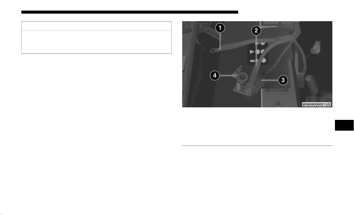
SERVICING AND MAINTENANCE 513
If you are storing your vehicle for more than 21 days, we
recommend that you take the following steps to minimize
the drain on your vehicle's battery:
• Disconnect the negative cable from battery.
• If your
vehicle is equipped with Stop/Start system then
disconn
ect both the main and supplemental negative
battery cables.
• Any time you store your vehicle or keep it out of service
(i.e.,
vacation) for two weeks or more, run the air condi-
tioning system at idle for about five minutes in the fresh air
a
nd high
blower setting. This will ensure adequate system
lubrication to minimize the possibility of compressor
damage when the system is started again.
• If assistance is needed to disconnect the battery system, see
your aut
horized dealer.
Battery Cable Disconnect
CAUTION!
If the negative battery cables are not isolated properly it
can caus
e a potential power spike or surge in the system,
resulting in damage to essential electrical components.
1 — Supplemental Negative Battery Cable
2 — Main Negative Battery Cable
3 — Intelligent Battery Sensor (IBS)
4 — Main Negative Battery Terminal
7

514 SERVICING AND MAINTENANCE
NOTE:
• You must isolate the supplemental battery connection
point,
as well as the main battery terminal from the post,
as shown in the image, to fully de-energize both batteries
for storage. If assistance is needed to disconnect the battery
system, see your authorized dealer.
• Do not disconnect the Intelligent Battery Sensor (IBS), or your
Stop/S
tart system may not function for up to 24 hours, due to
the IBS being set into learn mode.
BODYWORK
Protection From Atmospheric Agents
Vehicle body care requirements vary according to
geographic locations and usage. Chemicals that make roads
passable in snow and ice and those that are sprayed on trees
and road surfaces during other seasons are highly corrosive
to the metal in your vehicle. Outside parking, which exposes
your vehicle to airborne contaminants, road surfaces on
which the vehicle is operated, extreme hot or cold weather
and other extreme conditions will have an adverse effect on
paint, metal trim, and underbody protection.
The following maintenance recommendations will enable
you to o
btain maximum benefit from the corrosion resistance
built into your vehicle.
What Causes Corrosion?
Corrosion is the result of deterioration or removal of paint
and pro
tective coatings from your vehicle.
The most common causes are:
• R
oad salt, dirt and moisture accumulation.
• Stone
and gravel impact.
• Insect
s, tree sap and tar.
• Salt i
n the air near seacoast localities.
• Atmosp
heric fallout/industrial pollutants.
Body And Underbody Maintenance
Cleaning Headlights
Your vehicle is equipped with plastic headlights and fog
lights t
hat are lighter and less susceptible to stone breakage
than glass headlights.
Plastic is not as scratch resistant as glass and therefore
differe
nt lens cleaning procedures must be followed.
To minimize the possibility of scratching the lenses and
reducin
g light output, avoid wiping with a dry cloth. To
remove road dirt, wash with a mild soap solution followed
by rinsing.

SERVICING AND MAINTENANCE 515
Do not use abrasive cleaning components, solvents, steel
wool or other aggressive material to clean the lenses.
Preserving The Bodywork
Washing
• Wash your vehicle regularly. Always wash your vehicle in
the sh
ade using Mopar Car Wash, or a mild car wash soap,
and rinse the panels completely with clear water.
• If insects, tar, or other similar deposits have accumulated
on your
vehicle, use Mopar Super Kleen Bug and Tar
Remover to remove.
• Use a high quality cleaner wax, such as Mopar Cleaner
Wax to
remove road film, stains and to protect your paint
finish. Take care never to scratch the paint.
• Avoid using abrasive compounds and power buffing that
may dim
inish the gloss or thin out the paint finish.
Special Care
• If you drive on salted or dusty roads or if you drive near
the oc
ean, hose off the undercarriage at least once a month.
• It is important that the drain holes in the lower edges of the
doors,
rocker panels, and trunk be kept clear and open.
• If you detect any stone chips or scratches in the paint,
touch
them up immediately. The cost of such repairs is
considered the responsibility of the owner.
• If your vehicle is damaged due to a collision or similar
cause
that destroys the paint and protective coating, have
your vehicle repaired as soon as possible. The cost of such
repairs is considered the responsibility of the owner.
• If you carry special cargo such as chemicals, fertilizers,
de-ice
r salt, etc., be sure that such materials are well pack-
aged and sealed.
• I
f a lot of driving is done on gravel roads, consider mud or
stone
shields behind each wheel.
• Use Mopar Touch Up Paint on scratches as soon as
possib
le. An authorized dealer has touch up paint to
match the color of your vehicle.
CAUTION!
• Do not use abrasive or strong cleaning materials such as
steel
wool or scouring powder that will scratch metal
and painted surfaces.
• Use of power washers exceeding 1,200 psi (8,274 kPa)
can re
sult in damage or removal of paint and decals.
7

516 SERVICING AND MAINTENANCE
Appearance Care For Fabric Top Models
To maintain the appearance of your vehicle's interior trim
and top
, follow these precautions:
• Avoid leaving your vehicle unattended with the top down,
as exp
osure to sun or rain may damage interior trim.
• Do not use harsh cleaners or bleaching agents on top mate-
rial,
as damage may result.
• D
o not allow any vinyl cleaner to run down and dry on the
paint,
leaving a streak.
• After cleaning your vehicle's fabric top, always make sure
it is
completely dry before lowering.
• Be especially careful when washing the windows by
followi
ng the directions for “Care of Fabric Top
Windows.”
Washing – Use Mo
par Car Wash or equivalent, or mild soap
suds, lukewarm water, and a brush with soft bristles. If extra
cleaning is required, use Mopar Convertible Cloth Top
Cleaner or equivalent, or a mild foaming cleaner on the
entire top, but support the top from underneath.
Rinsing – Be sure to remove all traces of cleaner by rinsing
the to
p thoroughly with clean water. Remember to allow the
top to dry before lowering it.
CAUTION!
Failure to follow these cautions may cause interior water
d
amage,
stains or mildew on the top material:
• Avoid high-pressure car washes, as they can damage
the top
material. Also, increased water pressure may
force past the weather strips.
• It is recommended that the top be free of water prior to
opening
it. Operating the top, opening a door or
lowering a window while the top is wet may allow
water to drip into the vehicle's interior.
• Use care when washing the vehicle, water pressure
direct
ed at the weather strip seals may cause water to
leak into the vehicle's interior.
• Careless handling and storage of the removable roof
panels
may damage the seals, causing water to leak into
the vehicle's interior.
• The front panel(s) must be positioned properly to
ensure
sealing. Improper installation can cause water to
leak into the vehicle's interior.

SERVICING AND MAINTENANCE 517
Care Of Fabric Top Windows
Your vehicle's fabric top has pliable plastic windows which
can be
scratched unless special care is taken by following
these directions:
• Never use a dry cloth to remove dust. Instead, use a
micro-
fiber towel or soft cotton cloth moistened with cold or
warm, c
lean water, and wipe across the window, not up
and down. Mopar Jeep Soft Glass Window Cleaner or
equivalent will safely clean all plastic windows without
scratching. It removes fine scratches to improve visibility
and provides UV protection to help prevent yellowing.
• When washing, never u
se hot water or anything stronger
than a mild soap. Never use solvents such as alcohol or
harsh cleaning agents.
• Always rinse thoroughly with cold water, then wipe with
a soft
and slightly moist, clean cloth.
• When removing frost, snow or ice, never u
se a scraper or
de-icing chemicals. Use warm water only if you must
clean the window quickly.
• Debris (sand, mud/dirt, dust, or salt) from off-road
drivin
g will have an impact on plastic retainer operation.
Even normal on-road driving and vehicle washing will
eventually impact window plastic retainer operation. To
maintain ease of use of the window plastic retainers, each
window plastic retainer should be cleaned and lubricated
regularly. Clean them with a mild soap solution and a
small brush. Cleaning products are available through an
authorized dealer.
• Never paste stickers, gummed labels or any tape to the
windows.
Adhesives are hard to remove and may damage
the windows.
7
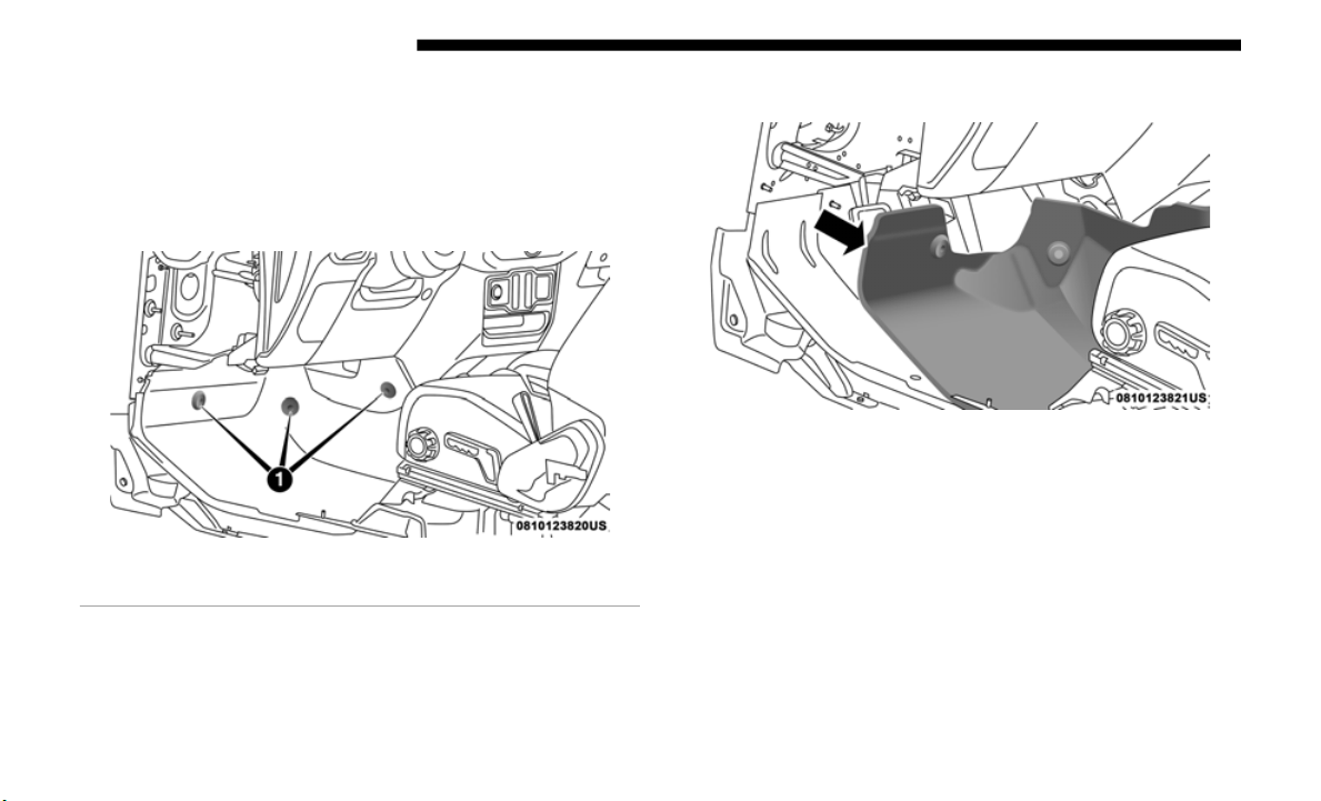
518 SERVICING AND MAINTENANCE
INTERIORS
Carpet Removal
Front Carpets (Two And Four Door Models):
1. Remove the front grommets.
Front Car
pet
2. Pull the carpet out from the front to the rear.
Front Car
pet Pulled Away
1 — Grommets
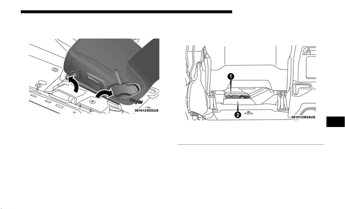
SERVICING AND MAINTENANCE 519
3. Remove the grommets under the front seat. First for the
rear carpet and then the front carpet.
Front And Rear Carpet Split
4. Under the back of the front seat, open the carpet split and
then pull out the rear edge and slide the carpet to the front
(do not remove the harness).
Rear Underside Of Front Seat
1 — Harness
2 — Carpet Split
7
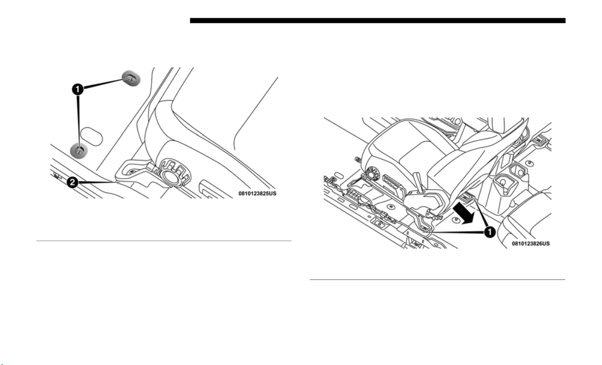
520 SERVICING AND MAINTENANCE
5. Finally open the carpet split around seat bracket and then
remove the last two grommets.
Front Seat And Floor
6. W
hen reinstalling carpet please preform these steps in
reverse
order making sure that the carpet is tucked under
the scuffs, B pillar, console, and refasten grommets.
Rear Carpet (Four Door Models):
1. Remove the grommets under the front seat (one left and
one righ
t).
2. T
hen pull the carpet out, to the rear and open the carpet
s
plit a
round the front seats brackets.
Pull Toward The Rear Of Vehicle
1 — Grommets
2 — Carpet Split
1 — Carpet Split
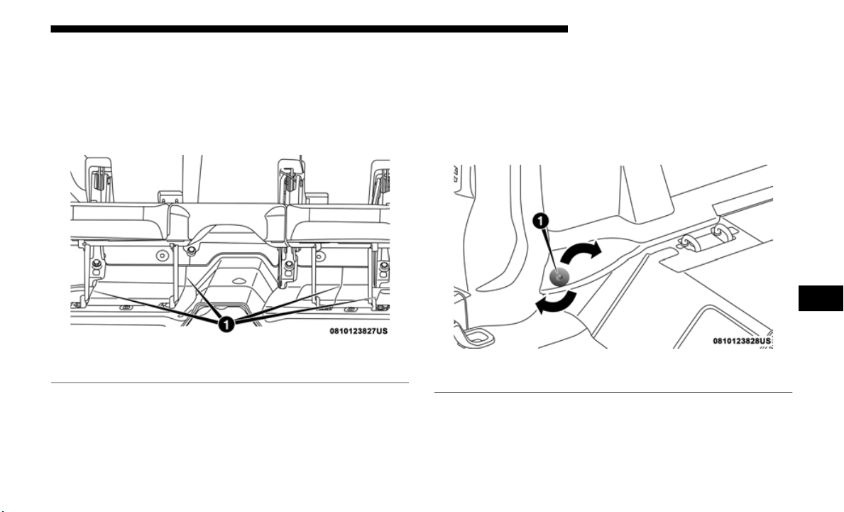
SERVICING AND MAINTENANCE 521
3. Remove the grommets under the rear seat (one left and
one right). First the grommet for the cargo carpet and
then the rear carpet.
4. Pull the carpet out to the front and open the carpet split
around
the rear seats brackets.
Under Rear Seat
5. W
hen reinstalling carpet please preform these steps in
reverse
order making sure that the carpet is tucked under
the scuffs, B pillar, console, and refasten grommets.
Rear Carpet (Two Door Models):
1. Remove the rear seats.
2. Remov
e the sides grommets (one left and one right). First
the grom
met from the side carpet and then the rear
carpet.
Side Carpet
3. Remove the grommets under the front seat (one left and
one righ
t).
1 — Carpet Split
1 — Grommet
7
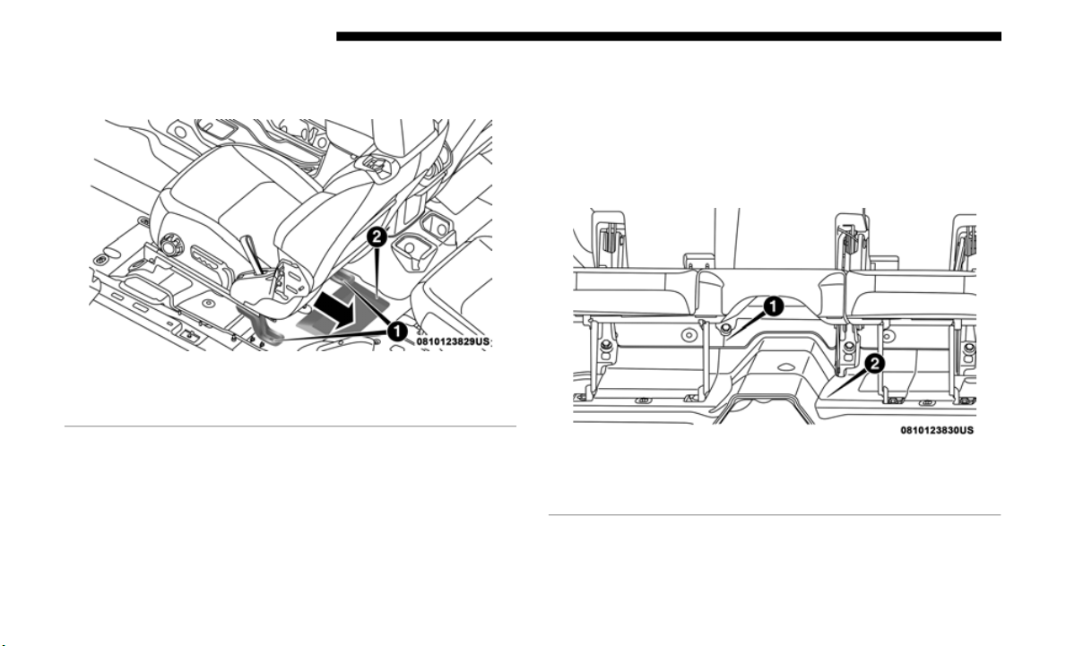
522 SERVICING AND MAINTENANCE
4. Then pull the carpet out to the rear and open the carpet
split around the front seats brackets.
Pull Carpet To The Rear
5. W
hen reinstalling carpet please preform these steps in
reverse
order making sure that the carpet is tucked under
the scuffs, B pillar, console, and refasten grommets.
Cargo Carpet (Four Door Models):
1. Remove the grommets under the rear seat (one left and
one righ
t).
2. P
ull the carpet out to the rear and open the carpet split
a
round
the seat belt attachment.
Under Rear Seat
1 — Carpet Split
2 — Rear Carpet
1 — Carpet Split
2 — Rear Carpet

SERVICING AND MAINTENANCE 523
3. Remove the carpet under the load floor and the side
support and then pull the carpet out.
Rear Load Floor
4. W
hen reinstalling carpet please preform these steps in
reverse
order making sure that the carpet is tucked under
the scuffs, B pillar, console, and refasten grommets.
Cargo Carpet (Four Door Models) With Gap Hider:
1. Remove the grommets under the rear seat (one left and
one righ
t).
2. P
ull the carpet out to the front and open the carpet split
a
round
the seat belt attachment and under the center seat
bracket.
Under Rear Seat
1 — Side Supports
2 — Load Floor
1 — Carpet Split
2 — Grommets
3 — Rear Carpet
7
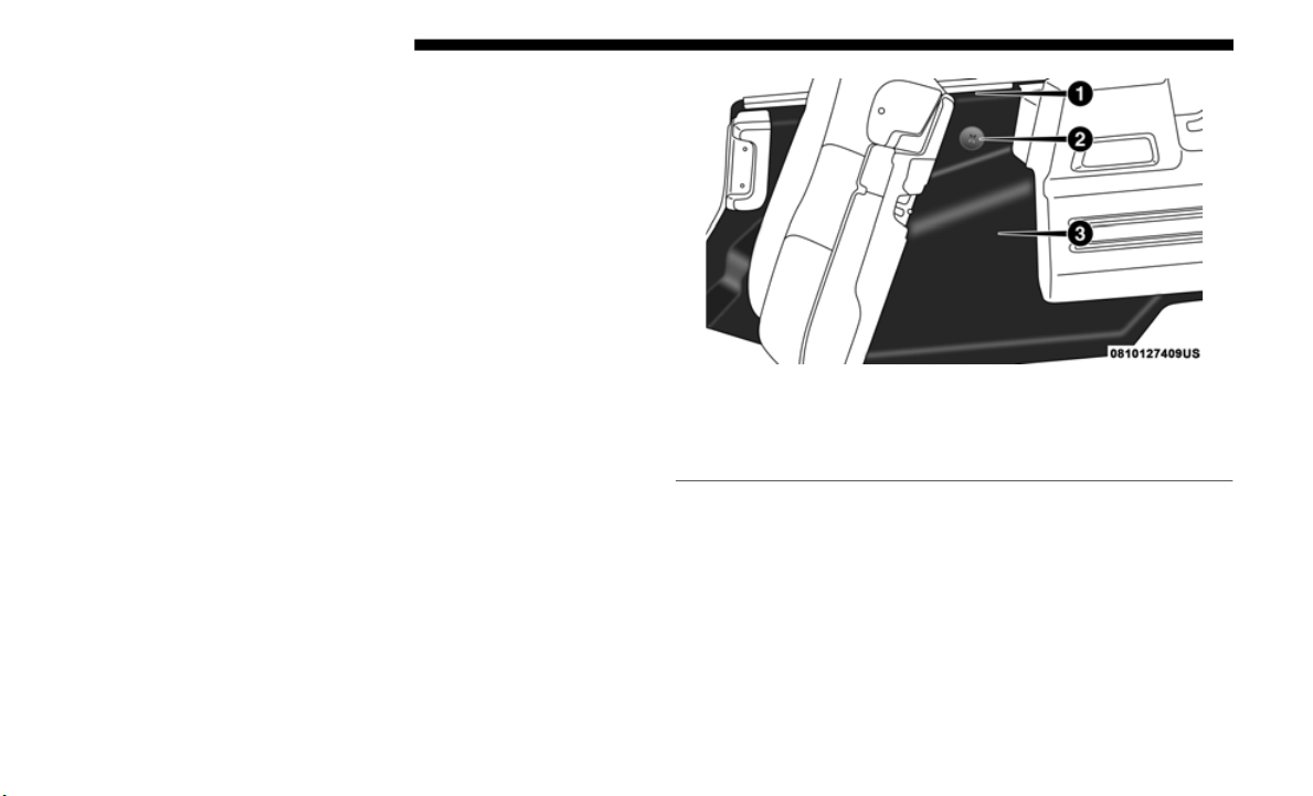
524 SERVICING AND MAINTENANCE
3. When reinstalling carpet please preform these steps in
reverse order making sure that the carpet is tucked under
the scuffs, B pillar, console, and refasten grommets.
Side Carpet (Four Door Models):
1. Remove the side grommet (one left and one right).
2. Pull
the carpet out starting on the top flange, then all
around
the perimeter and open the carpet split around
the seat belt attachment.
Inside Sidewall
3. When reinstalling carpet please preform these steps in
revers
e order making sure that the carpet is tucked under
the scuffs, B pillar, console, and refasten grommets.
1 — Top Flange
2 — Grommet
3 — Side Carpet
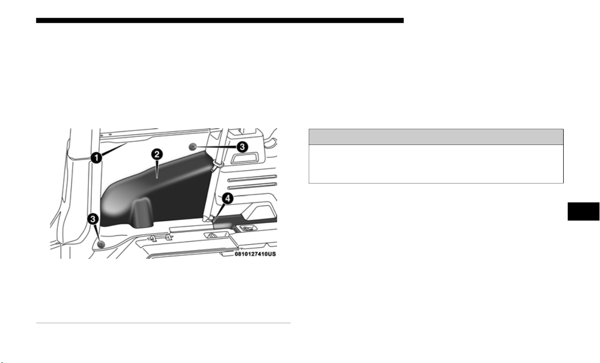
SERVICING AND MAINTENANCE 525
Side Carpet (Two Door Models):
1. Remove the side grommet and then the lower one (left
and ri
ght).
2. P
ull the carpet out starting on the top flange, then all
a
round
the perimeter and open the carpet split around
the seat belt attachment.
Inside Sidewall
3. When reinstalling carpet please preform these steps in
revers
e order making sure that the carpet is tucked under
the scuffs, B pillar, console, and refasten grommets.
Seats And Fabric Parts
Use Mopar Total Clean to clean fabric upholstery and
carpeting.
Seat Belt Maintenance
Do not bleach, dye or clean the belts with chemical solvents
or abra
sive cleaners. This will weaken the fabric. Sun
damage can also weaken the fabric.
If the belts need cleaning, use a mild soap solution or luke-
warm water. Do not remove the belts from the vehicle to
wash the
m. Dry with a soft cloth.
Replace the belts if they appear frayed or worn or if the
buckles
do not work properly.
1 — Top Flange
2 — Side Carpet
3 — Grommets
4 — Carpet Split
WARNING!
Do not use volatile solvents for cleaning purposes. Many
are pote
ntially flammable, and if used in closed areas
they may cause respiratory harm.
7

526 SERVICING AND MAINTENANCE
Plastic And Coated Parts
Use Mopar Total Clean to clean vinyl upholstery.
Cleaning Plastic Instrument Cluster Lenses
The lenses in front of the instruments in this vehicle are
molded
in clear plastic. When cleaning the lenses, care must
be taken to avoid scratching the plastic.
1. Clean with a wet soft cloth. A mild soap solution may be
used, b
ut do not use high alcohol content or abrasive
cleaners. If soap is used, wipe clean with a clean damp cloth.
2. Dry with a soft cloth.
Leather Parts
Mopar Total Clean is specifically recommended for leather
upholstery.
Your leather upholstery can be best preserved by regular
cleanin
g with a damp soft cloth. Small particles of dirt can act
as an abrasive and damage the leather upholstery and
should be removed promptly with a damp cloth. Stubborn
soils can be removed easily with a soft cloth and Mopar Total
Clean. Care should be taken to avoid soaking your leather
upholstery with any liquid. Please do not use polishes, oils,
cleaning fluids, solvents, detergents, or ammonia-based
cleaners to clean your leather upholstery. Application of a
leather conditioner is not required to maintain the original
condition.
WARNING!
A frayed or torn belt could rip apart in a collision and
leave you
with no protection. Inspect the belt system
periodically, checking for cuts, frays, or loose parts.
Damaged parts must be replaced immediately. Do not
disassemble or modify the system. Seat belt assemblies
must be replaced after a collision if they have been
damaged (i.e., bent retractor, torn webbing, etc.).
CAUTION!
• Direct contact of air fresheners, insect repellents,
suntan
lotions, or hand sanitizers to the plastic,
painted, or decorated surfaces of the interior may cause
permanent damage. Wipe away immediately.
• Damage caused by these type of products may not be
covered
by your New Vehicle Limited Warranty.

SERVICING AND MAINTENANCE 527
NOTE:
If equipped with light colored leather, it tends to show any
foreign
material, dirt, and fabric dye transfer more so than
darker colors. The leather is designed for easy cleaning, and
FCA recommends Mopar total care leather cleaner applied
on a cloth to clean the leather seats as needed.
Glass Surfaces
All glass surfaces should be cleaned on a regular basis with
Mopar Glass Cleaner, or any commercial household-type
glass cleaner. Never use an abrasive type cleaner. Use
caution when cleaning the inside rear window equipped
with electric defrosters or windows equipped with radio
antennas. Do not use scrapers or other sharp instruments
that may scratch the elements.
When cleaning the rear view mirror, spray cleaner on the
towel or
cloth that you are using. Do not spray cleaner
directly on the mirror.
CAUTION!
Do not use Alcohol and Alcohol-based and/or Ketone
based c
leaning products to clean leather upholstery, as
damage to the upholstery may result.
7
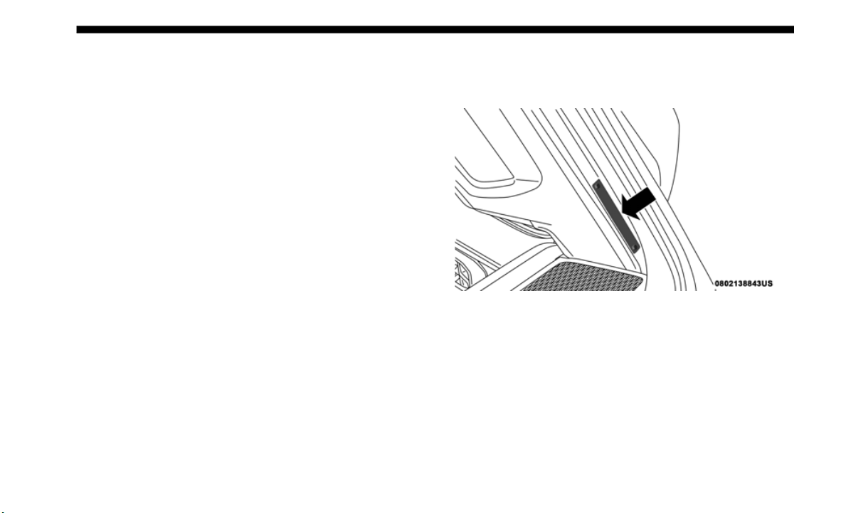
528
TECHNICAL SPECIFICATIONS
VEHICLE IDENTIFICATION NUMBER
The Vehicle Identification Number (VIN) is found on the left
front corner of the A pillar, visible from outside of the vehicle
through the windshield. This number also appears under
-
body, on the right side of the frame rail near the center of the
vehicle,
as well as on the Automobile Information Disclosure
Label affixed to a window on your vehicle. Save this label for
a convenient record of your vehicle identification number
and optional equipment.
The VIN is also stamped on either right or left hand side of
the engin
e block.
Vehicle Identification Number
NOTE:
It is illegal to remove or alter the VIN plate.

TECHNICAL SPECIFICATIONS 529
BRAKE SYSTEM
Your vehicle is equipped with dual hydraulic brake systems.
If either of the two hydraulic systems loses normal capa-
bility, the remaining system will still function. However,
t
here wi
ll be some loss of overall braking effectiveness. You
may notice increased pedal travel during application, greater
pedal force required to slow or stop, and potential activation
of the Brake Warning Light.
In the event power assist is lost for any reason (i.e., repeated
brake ap
plications with the engine OFF) the brakes will still
function. However, the effort required to brake the vehicle
will be much greater than that required with the power
system operating.
WHEEL AND TIRE TORQUE SPECIFICATIONS
Proper lug nut/bolt torque is very important to ensure that
the wheel is properly mounted to the vehicle. Any time a
wheel has been removed and reinstalled on the vehicle, the
lug nuts/bolts should be torqued using a properly calibrated
torque wrench using a high quality six sided (hex) deep wall
socket.
Torque Specifications
**Use only your authorized dealer recommended lug nuts/
bolts and clean or remove any dirt or oil before tightening.
Inspect the wheel mounting surface prior to mounting the
tire an
d remove any corrosion or loose particles.
Lug Nut/Bolt
Torque
**L
ug Nut/Bolt
Size
Lug Nut/Bolt
Socket Size
130 Ft-Lbs
(176 N·m
)
M14 x 1.50 22 mm
8
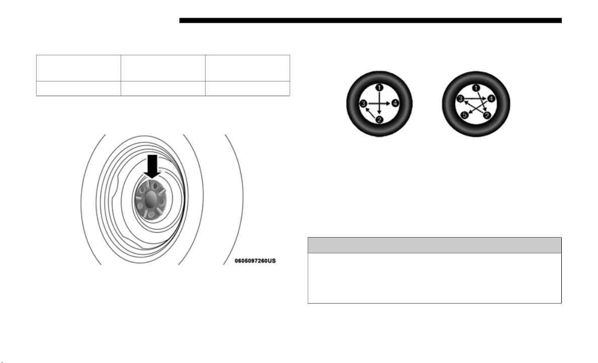
530 TECHNICAL SPECIFICATIONS
Spare Tire Torque Specifications
Spare tire torque is for the spare tire carrier located on the
tailgate.
W
heel Mounting Surface
Tighten the lug nuts/bolts in a star pattern until each nut/
bolt has
been tightened twice. Ensure that the socket is fully
engaged on the lug nut/bolt (do not insert it halfway).
Torque Patterns
After 25 miles (40 km), check the lug nut/bolt torque to be
sure tha
t all the lug nuts/bolts are properly seated against
the wheel.
Lug Nut/Bolt
Torque
**Lu
g Nut/Bolt
Size
Lug Nut/Bolt
Socket Size
59 Ft-Lbs (80 N·m) M14 x 1.50 22 mm
WARNING!
To avoid the risk of forcing the vehicle off the jack, do
not tighte
n the lug nuts/bolts fully until the vehicle has
been lowered. Failure to follow this warning may result
in personal injury.
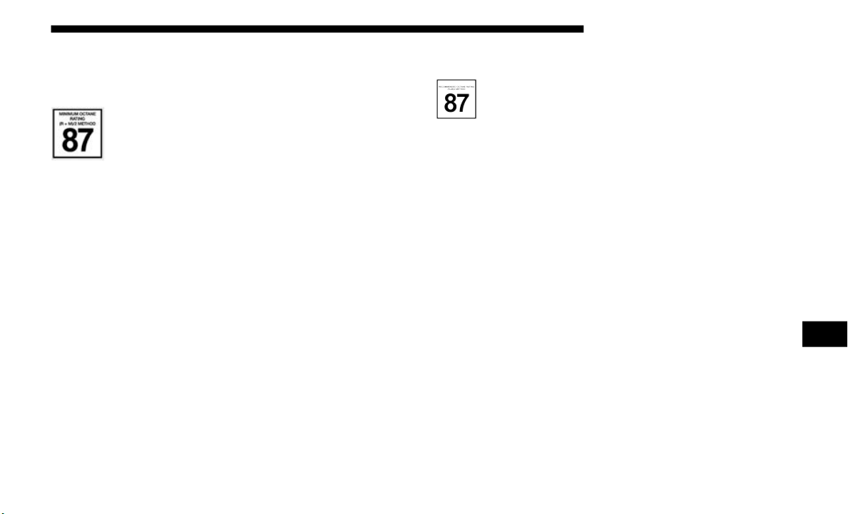
TECHNICAL SPECIFICATIONS 531
FUEL REQUIREMENTS
2.0L Engine
This engine is designed to meet all emission
requirements, and provide satisfactory fuel
economy a
nd performance, when using
high-quality unleaded “regular” gasoline having
an octane rating of 87, as specified by the (R+M)/2
method.
The use
of 91 or higher octane “premium” gasoline will
allow these engines to operate to optimal performance. This
increase in performance is most noticeable in hot weather or
other heavier load conditions, such as while towing.
While operating on gasoline with the required octane
number,
hearing a light knocking sound from the engine is
not a cause for concern. However, if the engine is heard
making a heavy knocking sound, see your dealer immedi
-
ately. Use of gasoline with a lower than recommended
o
ctane n
umber can cause engine failure and may void or not
be covered by the New Vehicle Limited Warranty.
Poor quality gasoline can cause problems such as hard
starting,
stalling, and hesitations. If you experience these
symptoms, try another brand of gasoline before considering
service for the vehicle.
3.6L Engine
This engine is designed to meet all emissions regula-
tions and provide satisfactory fuel economy and
performa
nce when using high-quality unleaded
“Regular” gasoline having an octane rating of 87 as specified
by the (R+M)/2
method. The use of higher octane
“Premium
” gasoline will not provide any benefit over
“Regular” gasoline in these engines.
While operating on gasoline with an octane number of 87,
hearing a
light knocking sound from the engine is not a cause
for concern. However, if the engine is heard making a heavy
knocking sound, see your dealer immediately. Use of gaso
-
line with an octane number lower than 87 can cause engine
f
ailure
and may void or not be covered by the New Vehicle
Limited Warranty.
Poor quality gasoline can cause problems such as hard
starting,
stalling, and hesitations. If you experience these
symptoms, try another brand of gasoline before considering
service for the vehicle.
8

532 TECHNICAL SPECIFICATIONS
Reformulated Gasoline
Many areas of the country require the use of cleaner burning
gasoline referred to as “Reformulated Gasoline”. Reformu-
lated gasoline contains oxygenates and are specifically
b
lended
to reduce vehicle emissions and improve air quality.
The use of reformulated gasoline is recommended. Properly
b
l
ended
reformulated gasoline will provide improved
performance and durability of engine and fuel system
components.
Materials Added To Fuel
Besides using unleaded gasoline with the proper octane
rating, gasolines that contain detergents, corrosion and
stability additives are recommended. Using gasolines that
have these additives will help improve fuel economy, reduce
emissions, and maintain vehicle performance.
Designated TOP TIER Detergent Gasoline contains a
higher level of detergents to further aide in mini-
mizing engine and fuel system deposits. When avail-
able, the usage of TOP TIER Detergent gasoline is
r
ecommen
ded. Visit www.toptiergas.com for a list of TOP
TIER Detergent Gasoline Retailers.
Indiscriminate use of fuel system cleaning agents should be
a
voided.
Many of these materials intended for gum and
varnish removal may contain active solvents or similar
ingredients. These can harm fuel system gasket and
diaphragm materials.
Gasoline/Oxygenate Blends
Some fuel suppliers blend unleaded gasoline with oxygen-
ates such as ethanol.
Problems that result from using gasoline containing more
t
han 15%
ethanol (E-15) or gasoline containing methanol are
not the responsibility of the manufacturer and may void or
not be covered under New Vehicle Limited Warranty.
CAUTION!
DO NOT use E-85, gasoline containing methanol, or
gasoline
containing more than 15% ethanol (E-15). Use of
these blends may result in starting and drivability
problems, damage critical fuel system components, cause
emissions to exceed the applicable standard, and/or cause
the Malfunction Indicator Light to illuminate. Please
observe pump labels as they should clearly communicate
if a fuel contains greater than 15% ethanol (E-15).

TECHNICAL SPECIFICATIONS 533
(Continued)
Do Not Use E-85 In Non-Flex Fuel Vehicles
Non-Flex Fuel Vehicles (FFV) are compatible with gasoline
containing up to 15% ethanol (E-15). Use of gasoline with
higher ethanol content may void the New Vehicle Limited
Warranty.
If a Non-FFV vehicle is inadvertently fueled with E-85 fuel,
the engi
ne will have some or all of these symptoms:
• Operate in a lean mode.
• OBD II
Malfunction Indicator Light on.
• Poor e
ngine performance.
• Poor c
old start and cold drivability.
• Increa
sed risk for fuel system component corrosion.
CNG And LP Fuel System Modifications
Modifications that allow the engine to run on Compressed
Natural Gas (CNG) or Liquid Propane (LP) may result in
damage to the engine, emissions, and fuel system compo
-
nents. Problems that result from running CNG or LP are not
the res
ponsibility of the manufacturer and may void or not
be covered under the New Vehicle Limited Warranty.
MMT In Gasoline
Methylcyclopentadienyl Manganese Tricarbonyl (MMT) is a
manganese-containing metallic additive that is blended into
some gasoline to increase octane. Gasoline blended with
MMT provides no performance advantage beyond gasoline
of the same octane number without MMT. Gasoline blended
with MMT reduces spark plug life and reduces emissions
system performance in some vehicles. The manufacturer
recommends that gasoline without MMT be used in your
vehicle. The MMT content of gasoline may not be indicated
on the gasoline pump; therefore, you should ask your gaso
-
line retailer whether the gasoline contains MMT. MMT is
p
rohibi
ted in Federal and California reformulated gasoline.
Fuel System Cautions
CAUTION!
Follow these guidelines to maintain your vehicle’s
performa
nce:
• The use of leaded gasoline is prohibited by Federal
law. U
sing leaded gasoline can impair engine perfor-
mance and damage the emissions control system.
8

534 TECHNICAL SPECIFICATIONS
NOTE:
Intentional tampering with the emissions control system can
result
in civil penalties being assessed against you.
Carbon Monoxide Warnings
• An out-of-tune engine or certain fuel or ignition
malfunctions can cause the catalytic converter to over-
heat. If you notice a pungent burning odor or some
l
ight sm
oke, your engine may be out of tune or
malfunctioning and may require immediate service.
Contact an authorized dealer for service assistance.
• The use of fuel additives, which are now being sold as
octane
enhancers, is not recommended. Most of these
products contain high concentrations of methanol. Fuel
system damage or vehicle performance problems
resulting from the use of such fuels or additives is not
the responsibility of the manufacturer and may void or
not be covered under the New Vehicle Limited
Warranty.
CAUTION! (Continued)
WARNING!
Carbon monoxide (CO) in exhaust gases is deadly.
Follow the
precautions below to prevent carbon
monoxide poisoning:
• Do not inhale exhaust gases. They contain carbon
monoxide
, a colorless and odorless gas, which can kill.
Never run the engine in a closed area, such as a garage,
and never sit in a parked vehicle with the engine
running for an extended period. If the vehicle is
stopped in an open area with the engine running for
more than a short period, adjust the ventilation system
to force fresh, outside air into the vehicle.
• Guard against carbon monoxide with proper mainte-
nance.
Have the exhaust system inspected every time
the vehi
cle is raised. Have any abnormal conditions
repaired promptly. Until repaired, drive with all side
windows fully open.

TECHNICAL SPECIFICATIONS 535
FLUID CAPACITIES
U.S. Metric
Fuel (Approximate)
Two Door Models 17.5 Gallons 66 Liters
Four Door Models 21.5 Gallons 81 Liters
Engine Oil with Filter
2.0L Engine 5 Quarts 4.73 Liters
3.6L Engine 5 Quarts 4.73 Liters
Cooling System *
2.0L Engine (Mopar Antifreeze/Engine Coolant 10 Year/
1
50,000
Mile Formula or equivalent)
10.3 Quarts 9.7 Liters
2.0L Engine Intercooler without Motor Generator Unit
(MGU) (
Mopar Antifreeze/Engine Coolant 10 Year/
150,000 Mile Formula or equivalent)
3.2 Quarts 3.0 Liters
2.0L Engine Intercooler with Motor Generator Unit
(
MGU) (
Mopar Antifreeze/Engine Coolant 10 Year/
150,000 Mile Formula or equivalent)
3.5 Quarts 3.3 Liters
2.0L Battery Coolant (Mopar Antifreeze/Engine Coolant
1
0 Year
/150,000 Mile Formula or equivalent)
2.5 Quarts 2.4 Liters
3.6L Engine (Mopar Antifreeze/Engine Coolant 10 Year/
150,000
Mile Formula or equivalent)
11.2 Quarts 10.6 Liters
8

536 TECHNICAL SPECIFICATIONS
FLUIDS AND LUBRICANTS
Engine
3.6L Motor Generator Unit (MGU) (Mopar Antifreeze/
Engine Coolant 10 Year/150,000 Mile Formula or
equivalent)
1.9 Quarts 1.8 Liters
3.6L Battery Coolant (Mopar Antifreeze/Engine Coolant
1
0 Year
/150,000 Mile Formula or equivalent)
2.5 Quarts 2.4 Liters
* Includes coolant recovery bottle filled to MAX level.
U.S. Metric
Component Fluid, Lubricant, or Genuine Part
Engine Coolant
We recommend you use Mopar Antifreeze/Coolant 10 Year/150,000 Mile
Fo
rmula
OAT (Organic Additive Technology) or equivalent meeting the
requirements of FCA Material Standard MS.90032.
Intercooler/Motor Generator Unit
(if equipped)
We recommend you use Mopar Antifreeze/Coolant 10 Year/150,000 Mile
Fo
rmula
OAT (Organic Additive Technology) or equivalent meeting the
requirements of FCA Material Standard MS.90032.
Battery Coolant (if equipped)
We recommend you use Mopar Antifreeze/Coolant 10 Year/150,000 Mile
Fo
rmula
OAT (Organic Additive Technology) or equivalent meeting the
requirements of FCA Material Standard MS.90032.

TECHNICAL SPECIFICATIONS 537
Engine Oil — 2.0L Engine
We recommend you use Mopar API SN PLUS Certified SAE 5W-30 Full
S
yntheti
c Engine Oil which meets the requirements of FCA Material Standard
MS-13340. Equivalent full synthetic SAE 5W-30 engine oil can be used if it
meets API SN PLUS Certification. If SN PLUS or equivalent oil is unavailable
then please contact your local dealership for recommendation.
CAUTION!
Failure to use the recommended SN PLUS or equivalent oil can cause
engine d
amage not covered by the vehicle warranty.
Engine Oil — 3.6L Engine
We recommend you use API Certified SAE 0W-20 Engine Oil, meeting the
r
equire
ments of FCA Material Standard MS-6395 such as Mopar, Pennzoil,
and Shell Helix. Refer to your engine oil filler cap for correct SAE grade.
Engine Oil Filter
We recommend you use Mopar Engine Oil Filter or equivalent.
Spark Plugs
We recommend you use Mopar Spark Plugs.
Fuel Selection — 2.0L Engine
87 Octane Minimum – 91 Octane Recommended, 0-15% Ethanol.
Fuel Selection — 3.6L Engine
87 Octane, 0-15% Ethanol.
Component Fluid, Lubricant, or Genuine Part
8

538 TECHNICAL SPECIFICATIONS
(Continued)
CAUTION!
• Mixing of engine coolant (antifreeze) other than speci-
fied O
rganic Additive Technology (OAT) engine
coolant (
antifreeze), may result in engine damage and
may decrease corrosion protection. Organic Additive
Technology (OAT) engine coolant is different and
should not be mixed with Hybrid Organic Additive
Technology (HOAT) engine coolant (antifreeze) or any
“globally compatible” coolant (antifreeze). If a
non-OAT engine coolant (antifreeze) is introduced into
the cooling system in an emergency, the cooling system
will need to be drained, flushed, and refilled with fresh
OAT coolant (conforming to MS.90032), by an autho
-
rized dealer as soon as possible.
• Do not use water alone or alcohol-based engine coolant
(antifreeze) products. Do not use additional rust inhib
-
itors or antirust products, as they may not be compat-
ible with the radiator engine coolant and may plug the
r
adiator
.
• This vehicle has not been designed for use with
propyle
ne glycol-based engine coolant (antifreeze).
Use of propylene glycol-based engine coolant (anti
-
freeze) is not recommended.
CAUTION! (Continued)

TECHNICAL SPECIFICATIONS 539
Chassis
Component Fluid, Lubricant, or Genuine Part
Automatic Transmission – If Equipped
Use only Mopar ZF 8&9 Speed ATF Automatic Transmission Fluid or
e
quival
ent. Failure to use the correct fluid may affect the function or
performance of your transmission.
Manual Transmission – If Equipped
We recommend you use Mopar ATF+4 Automatic Transmission Fluid.
Transfer Case
We recommend you use Mopar ATF+4 Automatic Transmission Fluid.
Axle Differential (Front Axles)
We recommend you use Mopar Gear & Axle Lubricant (SAE 75W85) (API GL-5)
Axle Differential (Rear M200 Sales Code
D
RZ)
We r
ecommend you use Mopar Gear & Axle Lubricant (SAE 75W140)
(API GL-5).
Axle Differential (Rear M220 Sales Codes
D
RE/DRF)
We
recommend you use Mopar Gear & Axle Lubricant (SAE 75W85)
(API GL-5). Models equipped with Trac-Lok Limited Slip Differential require
a
frict
ion modifier additive.
Brake Master Cylinder
We recommend you use Mopar DOT 3 Brake Fluid, SAE J1703.
Power Steering Reservoir
We recommend you use Mopar Electric Steering Pump Fluid.
8
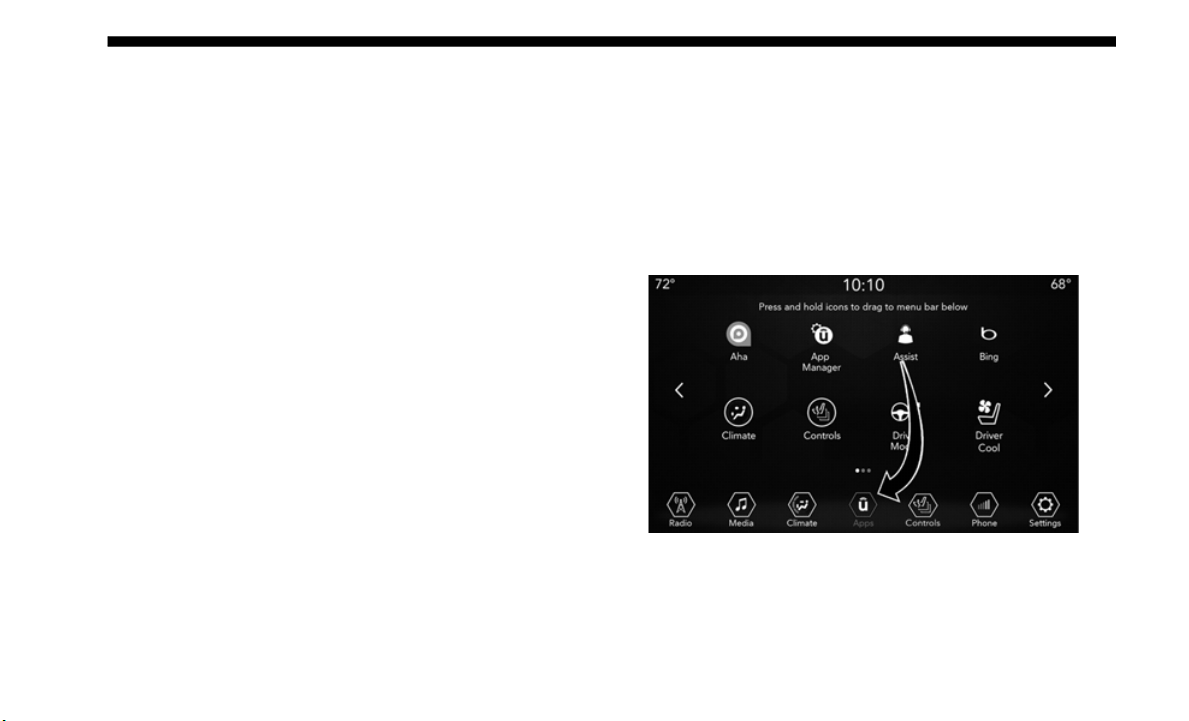
540
MULTIMEDIA
UCONNECT SYSTEMS
For detailed information about your Uconnect system, refer
to your Uconnect Owner’s Manual Supplement.
NOTE:
Uconnect screen images are for illustration purposes only
a
nd may n
ot reflect exact software for your vehicle.
DRAG & DROP MENU BAR
The Uconnect features and services in the main menu bar are
easily changed for your convenience. Simply follow these
steps:
Uconnect 4 Apps Menu

MULTIMEDIA 541
Uconnect 4C/4C NAV Apps Menu
1. Press the “Apps ” butto
n to open the App screen.
2. Press and hold, then drag the selected App to replace an
existin
g shortcut in the main menu bar.
The new shortcut will now be an active App/shortcut on
the main
menu bar.
CYBERSECURITY
Your vehicle may be a connected vehicle and may be
equipped with both wired and wireless networks. These
networks allow your vehicle to send and receive informa
-
tion. This information allows systems and features in your
vehicle
to function properly.
Your vehicle may be equipped with certain security features
to reduc
e the risk of unauthorized and unlawful access to
vehicle systems and wireless communications. Vehicle soft
-
ware technology continues to evolve over time and FCA US
LLC, worki
ng with its suppliers, evaluates and takes appro-
priate steps as needed. Similar to a computer or other
d
evices,
your vehicle may require software updates to
improve the usability and performance of your systems or to
reduce the potential risk of unauthorized and unlawful
access to your vehicle systems.
The risk of unauthorized and unlawful access to your vehicle
systems m
ay still exist, even if the most recent version of
vehicle software (such as Uconnect software) is installed.
9

542 MULTIMEDIA
NOTE:
• FCA US LLC or your dealer may contact you directly
regardi
ng software updates.
• To help further improve vehicle security and minimize the
potent
ial risk of a security breach, vehicle owners should:
• Routinely check www.drive
uconnect.com (U.S. Resi-
dents) or www.driveuconnect.ca (Canadian Residents)
to learn about available Uconnect software updates.
• O
nly connect and use trusted media devices (e.g.
person
al mobile phones, USBs, CDs).
Privacy of any wireless and wired communications cannot
be assu
red. Third parties may unlawfully intercept informa-
tion and private communications without your consent. For
f
urther
information, refer to “Data Collection & Privacy” in
your Uconnect Owner’s Manual Supplement or “Onboard
Diagnostic System (OBD II) Cybersecurity” in “Getting To
Know Your Instrument Panel”.
WARNING!
• It is not possible to know or to predict all of the
possibl
e outcomes if your vehicle’s systems are
breached. It may be possible that vehicle systems,
including safety related systems, could be impaired or
a loss of vehicle control could occur that may result in
an accident involving serious injury or death.
• ONLY insert media (e.g., USB, SD card, or CD) into
your vehi
cle if it came from a trusted source. Media of
unknown origin could possibly contain malicious soft
-
ware, and if installed in your vehicle, it may increase
the poss
ibility for vehicle systems to be breached.
• As always, if you experience unusual vehicle behavior,
take you
r vehicle to your nearest authorized dealer
immediately.
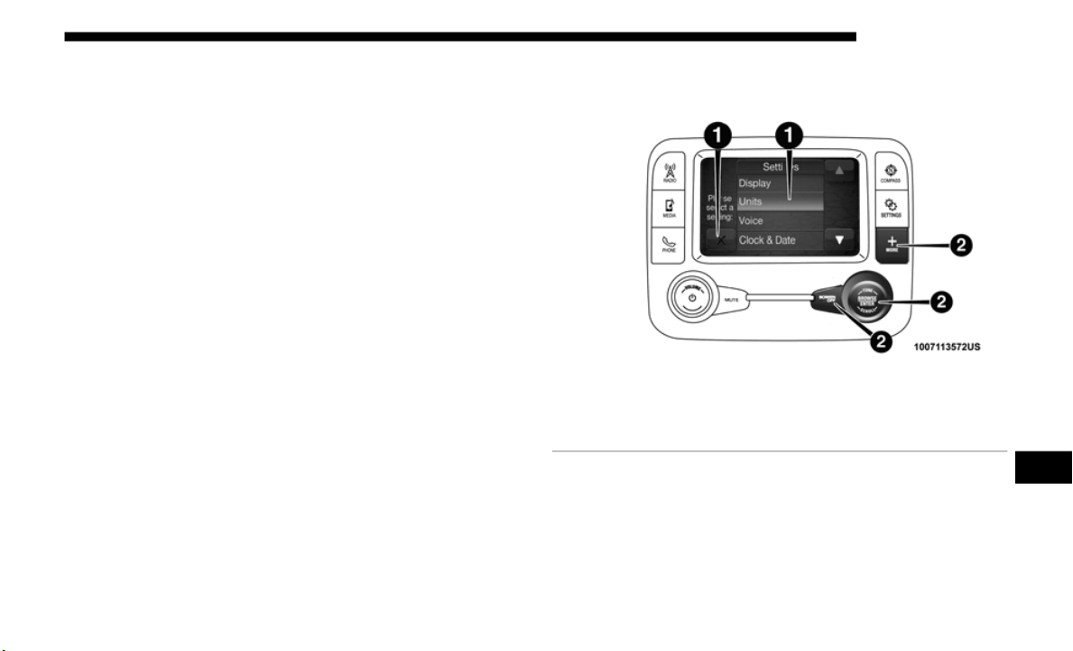
MULTIMEDIA 543
UCONNECT SETTINGS
The Uconnect system uses a combination of buttons on the
touchscreen and buttons on the faceplate located on the
center of the instrument panel that allow you to access and
change the customer programmable features. Many features
can vary by vehicle.
Buttons on the touchscreen are accessible on the Uconnect
touchscr
een.
Buttons on the faceplate are located below, and beside the Ucon-
nect system in the center of the instrument panel. In addition,
t
here is
a Scroll/Enter control knob located on the right side.
Turn the control knob to scroll through menus and change
settings (i.e., 30, 60, 90), push the center of the control knob one
or more times to select or change a setting (i.e., ON, OFF).
Your Uconnect system may also have Screen Off and Mute
buttons
on the faceplate.
Push the Screen Off button on the faceplate to turn off the
Uconnect
screen. Push the Screen Off button on the faceplate
a second time to turn the screen on.
Push the Back Arrow button on the faceplate to exit out of a
Menu or
certain option on the Uconnect system.
Customer Programmable Features —
Uconnect 3 Settings
Uconnect 3 Buttons On The Touchscreen And Buttons On
The Faceplate
Push the “Settings” button on the touchscreen to display the
settings
menu screen. In this mode the Uconnect system
allows you to access all of the available programmable
features.
1 — Uconnect Buttons On The Touchscreen
2 — Uconnect Buttons On The Faceplate
9

544 MULTIMEDIA
NOTE:
Only one touchscreen area may be selected at a time.
When making a selection, press the button on the touchscreen
to ente
r the desired mode. Once in the desired mode, press and
release the preferred setting and make your selection. Once the
setting is complete, either press the back arrow/Done button
on the touchscreen or the Back button on the faceplate to return
to the previous menu. Pressing the Up or Down Arrow buttons
on the right side of the screen will allow you to toggle up or
down through the available settings.
NOTE:
All settings should be changed with the ignition in the
“RUN” p
osition.
The following tables list the settings that may be found
wi
t
hin t
he Uconnect 3 radio, along with the selectable
options pertaining to each setting.
Language
After pressing the “Language” button on the touchscreen, the following settings will be available:
Display
After pressing the “Display” button on the touchscreen, the following settings will be available:
Setting Name Selectable Options
Language English Espanol Francais
Setting Name Selectable Options
Display Mode Auto Manual

MULTIMEDIA 545
Units
After pressing the “Units” button on the touchscreen, the following settings will be available:
Brightness + -
NOTE:
The “Brightness” setting can also be adjusted by selecting any point on the scale between the “+” and “-” buttons on the
touchsc
reen.
Touchscreen Beep On Off
Setting Name Selectable Options
Setting Name Selectable Options
Units US Metric Custom
NOTE:
• The “Metric” option changes the instrument cluster display to metric units of measure.
• The “C
ustom” option allows setting the “Fuel Consumption” (L/100km, or km/L) and “Pressure” (kPa, or bar) units of
measur
e independently.
9

546 MULTIMEDIA
Clock & Date
After pressing the “Clock & Date” button on the touchscreen, the following settings will be available:
Safety/Assistance
After pressing the “Safety/Assistance” button on the touchscreen, the following settings will be available:
Setting Name Selectable Options
Set Time and Format
12 hr 24 hr
AM PM
NOTE:
Within the “Set Time and Format” setting, press the corresponding arrow buttons on the touchscreen to adjust to the correct
time.
Show
Time Status — If Equipped On Off
Sync Time — If Equipped On Off
Setting Name Selectable Options
Forward Collision Warning —
If Equi
pped
Off Warning Only Warning & Braking
Forward Collision Warning
Sensiti
vity — If Equipped
Near Med Far
ParkView Backup Camera
Delay
On Of
f

MULTIMEDIA 547
NOTE:
The “ParkView Backup Camera Delay” setting determines whether or not the screen displays the rear view image with
dynamic
grid lines for up to ten seconds after the vehicle is shifted out of REVERSE. This delay is canceled if the vehicle’s
speed exceeds 8
mph (13 km/h), the transmission is shifted into PARK, or the ignition is switched to the OFF position.
ParkView Backup Camera
Active G
uide Lines
On Off
NOTE:
The “ParkView Backup Camera Active Guide Lines” setting overlays the Rear Backup Camera image with active, or
d
ynamic,
grid lines to help illustrate the width of the vehicle and its project back up path, based on the steering wheel posi-
tion when the option is checked. A dashed center line overlay indicates the center of the vehicle to assist with parking or
a
ligning
to a hitch/receiver.
ParkSense — If Equipped Sound Only Sound & Display
Rear ParkSense Volume — If
Equippe
d
Low Medium High
Blind Spot Alert — If
Equippe
d
Off Lights Lights & Chime
NOTE:
If your vehicle has experienced any damage in the area where the sensor is located, even if the fascia is not damaged, the
s
ensor
may have become misaligned. Take your vehicle to an authorized dealer to verify sensor alignment. A sensor that is
misaligned results in the Blind Spot Monitor (BSM) not operating to specification.
Hill Start Assist On Off
Setting Name Selectable Options
9

548 MULTIMEDIA
Lights
After pressing the “Lights” button on the touchscreen, the following settings will be available:
Setting Name Selectable Options
Headlight Off Delay
0 sec 30 sec
60 sec 90 sec
NOTE:
When the “Headlight Off Delay” feature is selected, it allows the adjustment of the amount of time the headlights remain on
after t
he engine is shut off.
Automatic High Beam Headlamps —
If Equi
pped
On Off
Daytime Running Lights On Off
NOTE:
When the “Daytime Running Light” feature is selected, the daytime running lights can be turned on or off. This feature is
only all
owed by law in the country of the vehicle purchase.
Flash Lights With Lock — If Equipped On Off
Interior Ambient Lights + -
NOTE:
The “Interior Ambient Lights” setting can also be adjusted by selecting any point on the scale between the “+” and “-”
buttons
on the touchscreen.

MULTIMEDIA 549
Doors & Locks
After pressing the “Doors & Locks” button on the touchscreen, the following settings will be available:
Setting Name Selectable Options
Auto Door Locks — If Equipped On Off
NOTE:
When this feature is selected, all doors will lock automatically when the vehicle reaches a speed of 12 mph (20 km/h).
Auto Unlock On Exit On Off
NOTE:
When this feature is selected, all doors will unlock when the vehicle is stopped and the transmission is in the PARK or
NEUTRAL
position and the driver's door is opened.
Flash Lights With Lock On Off
Horn With Lock On Off
Horn With Remote Start — If
Equippe
d
On Off
Remote Door Unlock/Door Unlock Driver All
NOTE:
When “Driver” is selected, only the driver's door will unlock on the first push of the key fob unlock button, you must push
the key f
ob unlock button twice to unlock the passenger's doors. When “All” is selected, all of the doors will unlock on the
first press of the key fob unlock button. If “All” is programmed, all doors will unlock no matter which Passive Entry
equipped door handle is grasped. If “Driver” is programmed, only the driver’s door will unlock when the driver’s door is
grasped. Touching the handle more than once will only result in the driver’s door opening once. If the driver’s door is
opened, the interior door lock/unlock switch can be used to unlock all doors (or use key fob).
9

550 MULTIMEDIA
Auto Comfort Systems — If Equipped
After pressing the “Auto-On Comfort Systems” button on the touchscreen, the following settings will be available:
Engine Off Options
After pressing the “Engine Off Options” button on the touchscreen, the following settings will be available:
Setting Name Selectable Options
Auto-On Driver Heated Seat
& Steer
ing Wheel With
Vehicle Start — If Equipped
Off Remote Start All Starts
NOTE:
When this feature is selected, the driver’s heated seat and heated steering wheel will automatically turn on when tempera-
tures are below 40° F (4.4° C). When temperatures are above 80° F (26.7° C), the driver vented seat will turn on.
Setting Name Selectable Options
Headlight Off Delay
0 sec 30 sec
60 sec 90 sec
NOTE:
When this feature is selected, it allows the adjustment of the amount of time the headlights remain on after the engine is shut off.

MULTIMEDIA 551
Audio
After pressing the “Audio” button on the touchscreen, the following settings will be available:
Setting Name Selectable Options
Equalizer Bass Mid Treble
NOTE:
When in this display you may adjust the “Bass”, “Mid”, and “Treble” settings. Adjust the settings with the “+” and “–”
setting
buttons on the touchscreen or by selecting any point on the scale between the “+” and “–” buttons on the touchscreen.
Bass/Mid/Treble also allow you to simply slide your finger up or down to change the setting as well as press directly on the
desired setting.
Balance/Fade
Up Arrow
Button
Do
wn Arrow
Button
Left Arrow
Button
Right Arrow
Button
Center “C”
Button
NOTE:
When in this display you may adjust the “Balance/Fade” of the audio by using the “Arrow” button on the touchscreen to
a
djust
the sound level from the front and rear or right and left side speakers. Press the “Center ‘C’ Button” on the touchscreen
to reset the balance and fade to the factory setting.
Speed Adjusted Volume Off 1 2 3
Surround Sound — If Equipped On Off
Loudness On Off
NOTE:
The “Loudness” feature improves sound quality at lower volumes when enabled.
9

552 MULTIMEDIA
Phone/Bluetooth
After pressing the “Phone/Bluetooth” button on the touchscreen, the following settings will be available:
SiriusXM Setup — If Equipped
After pressing the “SiriusXM Setup” button on the touchscreen, the following settings will be available:
AUX Volume Offset — If Equipped + -
NOTE:
The “AUX Volume Offset” feature provides the ability to tune the audio level for portable devices connected through the
AUX inp
ut.
Setting Name Selectable Options
Setting Name Selectable Options
Paired Phones List of Paired Phones
NOTE:
This feature shows which phones are paired to the Phone/Bluetooth system. For further information, refer to the Uconnect
Owner’s M
anual Supplement.
Setting Name Selectable Options
Channel Skip List of Channels
NOTE:
SiriusXM can be programmed to designate a group of channels that are the most desirable to listen to or to exclude undesir-
able channels while scanning. This feature allows you to select the channels you would like to skip.

MULTIMEDIA 553
Restore Settings
After pressing the “Restore Settings” button on the touchscreen, the following settings will be available:
Clear Personal Data
After pressing the “Clear Personal Data” button on the touchscreen, the following settings will be available:
Subscription Info Sirius ID
NOTE:
New vehicle purchasers or lessees will receive a free limited time subscription to SiriusXM Satellite Radio with your radio.
Fo
llowing
the expiration of the free services, it will be necessary to access the information on the Subscription Information
screen to re-subscribe.
1. Press the “Subscription Info” button on the touchscreen to access the Subscription Information screen.
2. Writ
e down the Sirius ID numbers for your receiver. To reactivate your service, either call the number listed on the screen
or vis
it the provider online.
Setting Name Selectable Options
Setting Name Selectable Options
Restore Settings OK Cancel
NOTE:
When the “Restore Settings” feature is selected, it will reset all settings to their default settings.
Setting Name Selectable Options
Clear Personal Data OK Cancel
NOTE:
When the “Clear Personal Data” feature is selected it will remove all personal data including Bluetooth devices and presets.
9
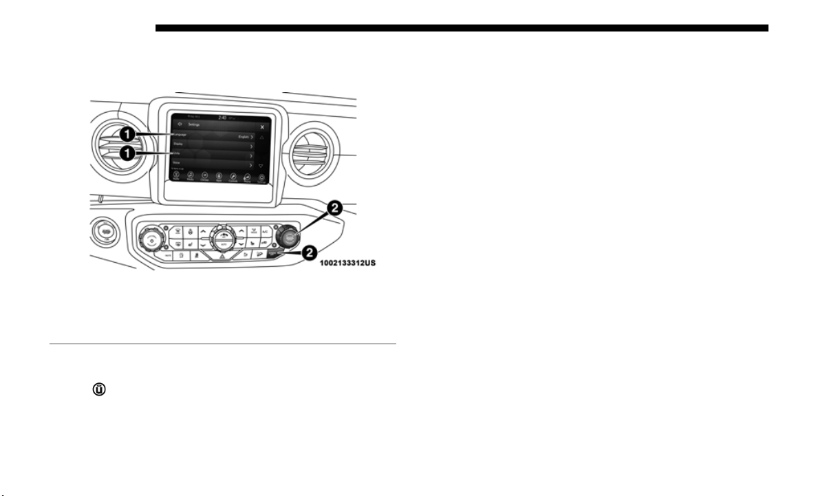
554 MULTIMEDIA
Customer Programmable Features — Uconnect 4
Settings
Uconnect 4 With 7-inch Display Touchscreen and Face-
plate Buttons
Press the “Settings” button on the bottom bar, or press the
“Apps ” b
utton, then press the “Settings” button on the
touchscreen to display the menu setting screen. In this mode
t
he Ucon
nect system allows you to access all of the available
programmable features.
NOTE:
• O
nly one touchscreen area may be selected at a time.
• Dependi
ng on the vehicles options, feature settings may
vary.
When
making a selection, press the button on the touch-
screen to enter the desired mode. Once in the desired mode,
p
ress an
d release the preferred setting “option” until a
check-mark appears next to the setting, showing that setting
has been selected. Once the setting is complete, either press
the Back Arrow button on the touchscreen to return to the
previous menu, or press the “X” button on the touchscreen
to close out of the settings screen. Pressing the Up or Down
Arrow button on the right side of the screen will allow you
to toggle up or down through the available settings.
The following tables list the settings that may be found
within th
e Uconnect 4 with 7-inch display radio, along with
the selectable options pertaining to each setting.
1 — Uconnect Buttons On The Touchscreen
2 — Uconnect Buttons On The Faceplate

MULTIMEDIA 555
Language
After pressing the “Language” button on the touchscreen, the following settings will be available:
Display
After pressing the “Display” button on the touchscreen, the following settings will be available:
Setting Name Selectable Options
Language English Espanol Francais
Setting Name Selectable Options
Display Mode Auto Manual
Display Brightness Headlights On + -
Display Brightness Headlights Off + -
Auto-Show Smartphone Display Upon
C
onnecti
on
On Off
Touchscreen Beep On Off
Control Screen Timeout On Off
Phone Pop-ups Displayed in Cluster On Off
9

556 MULTIMEDIA
Units
After pressing the “Units” button on the touchscreen, the following settings will be available:
Voice
After pressing the “Voice” button on the touchscreen, the following settings will be available:
Setting Name Selectable Options
Units US Metric Custom
NOTE:
• T
he “Metric” option changes the instrument cluster display to metric units of measure.
• The “C
ustom” option allows setting the “Distance, Fuel Consumption” (MPG (US), MPG(UK), L/100km, or km/L),“Pres-
sure”
(kPa, or bar) and “Temperature” (C, or F) units of measure independently.
Setting Name Selectable Options
Voice Response Length Brief Detailed
Show Command List Always With Help Never

MULTIMEDIA 557
Time & Date
After pressing the “Time & Date” button on the touchscreen, the following settings will be available:
Setting Name Selectable Options
Set Time Hours + -
NOTE:
The “Set Time Hours” feature allows you to adjust the hours.
Set Time Minutes + -
NOTE:
The “Set Time Minutes” feature allows you to adjust the minutes.
Time Format
12hrs 24hrs
AM PM
9

558 MULTIMEDIA
Camera
After pressing the “Camera” button on the touchscreen, the following settings will be available:
Setting Name Selectable Options
ParkView Backup Camera Delay On Off
NOTE:
The “ParkView Backup Camera Delay” setting determines whether or not the screen will display the rear view image with
dynamic
grid lines for up to ten seconds after the vehicle is shifted out of REVERSE. This delay will be canceled if the
vehicle’s speed exceeds 8
mph (13 km/h), the transmission is shifted into PARK, or the ignition is switched to the OFF posi-
tion.
ParkView Backup Camera Active
Guide L
ines
On Off
NOTE:
The “ParkView Backup Camera Active Guide Lines” feature overlays the Rear Backup Camera image with active, or
d
ynamic,
grid lines to help illustrate the width of the vehicle and its project back up path, based on the steering wheel posi-
tion when the option is checked. A dashed center line overlay indicates the center of the vehicle to assist with parking or
a
ligning
to a hitch/receiver.
ParkView Backup Camera Fixed
Guide L
ines
On Off

MULTIMEDIA 559
Safety/Driving Assistance — If Equipped
After pressing the “Safety/Driving Assistance” button on the touchscreen, the following settings will be available:
Setting Name Selectable Options
Forward Collision Warning — If Equipped Off Warning Only Warning & Braking
NOTE:
Applies brakes to slow the vehicle in case of potential forward collision, or applies brakes and a warning.
Forward Collision Warning Sensitivity — If
Equippe
d
Near Med Far
NOTE:
Sets the distance in which a Forward Collision Warning occurs.
ParkSense — If Equipped Sound Sound & Display
Rear ParkSense Volume
Low Medium High
Hill Start Assist On Off
Blind Spot Alert — If Equipped Off Lights Lights & Chime
9

560 MULTIMEDIA
Lights
After pressing the “Lights” button on the touchscreen, the following settings will be available:
Setting Name Selectable Options
Interior Ambient Lights + -
NOTE:
The “Interior Ambient Lights” setting can also be adjusted by selecting any point on the scale between the “+” and “-”
buttons
on the touchscreen.
Headlight Off Delay
0 sec 30 sec
60 sec 90 sec
NOTE:
When the “Headlight Off Delay” feature is selected, it allows the adjustment of the amount of time the headlights remain on
after t
he engine is shut off.
Daytime Running Lights On Off
NOTE:
When the “Daytime Running Light” feature is selected, the daytime running lights can be turned on or off. This feature is
only all
owed by law in the country of the vehicle purchase.
Auto Dim High Beams — If Equipped On Off
NOTE:
When the “Auto Dim High Beams” feature is selected, the high beam headlights activate/deactivate automatically under
certain
conditions.
Flash Lights With Lock — If Equipped On Off

MULTIMEDIA 561
Doors & Locks
After pressing the “Doors & Locks” button on the touchscreen, the following settings will be available:
Engine Off Options — If Equipped
After pressing the “Engine Off Options” button on the touchscreen, the following settings will be available:
Setting Name Selectable Options
Auto Unlock On Exit On Off
NOTE:
When this feature is selected, all doors will unlock when the vehicle is stopped and the transmission is in the PARK or
NEUTRAL
position and the driver's door is opened.
Flash Lights With Lock On Off
Remote Door Unlock Driver Door All Doors
Setting Name Selectable Options
Auto Door Locks — If Equipped On Off
NOTE:
When this feature is selected, all doors will lock automatically when the vehicle reaches a speed of 12 mph (20 km/h).
Setting Name Selectable Options
Doors On Engine Off Power Delay + -
Doors Off Engine Off Power Delay + -
Headlight Off Delay + -
9
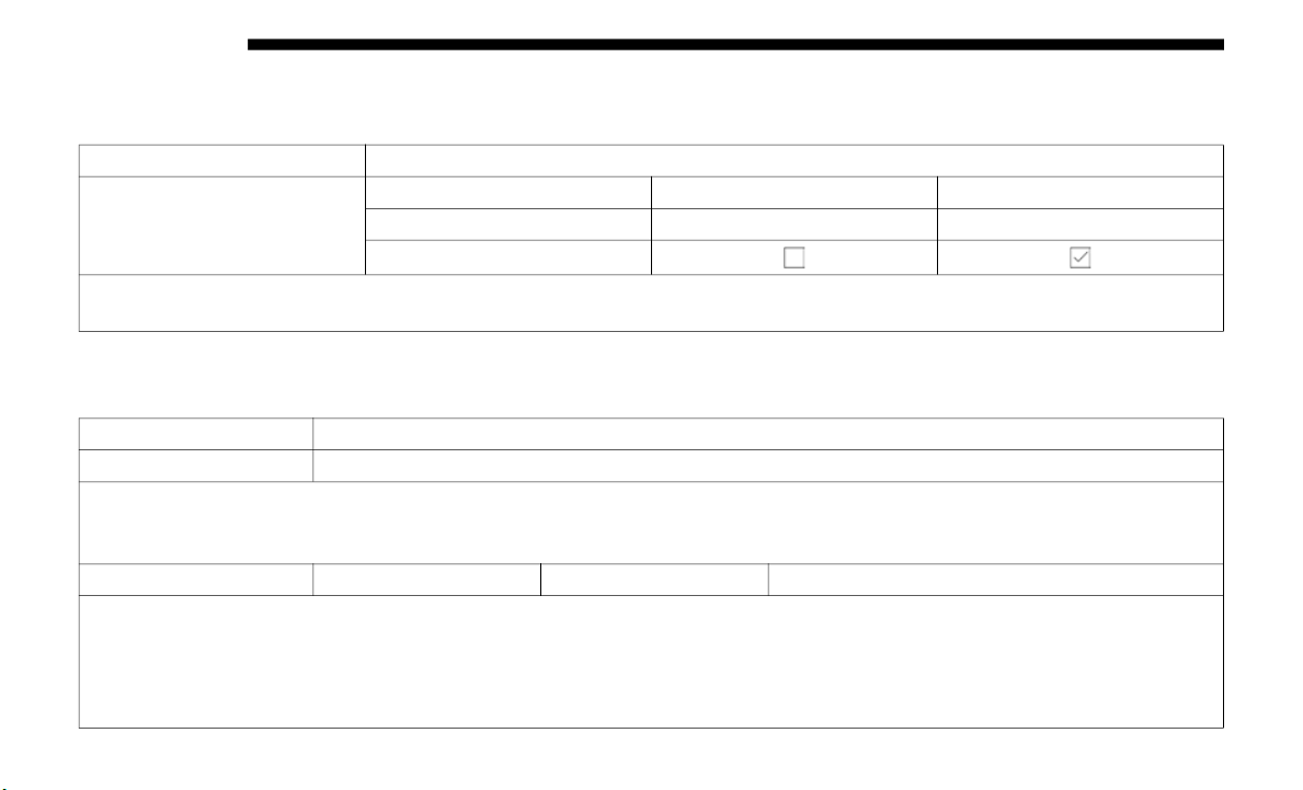
562 MULTIMEDIA
Aux Switches
After pressing the “Aux Switches” button on the touchscreen, the following settings will be available:
Audio
After pressing the “Audio” button on the touchscreen, the following settings will be available:
Setting Name Selectable Options
Aux 1-4
Type Latching Momentary
Power Source Battery Ignition
Recalled Last State
NOTE:
Holding last state conditions are met when switch type is set to latching and power source is set to ignition.
Setting Name Selectable Options
Balance & Fade Speaker Icon
NOTE:
When in this display you may adjust the “Balance & Fade” of the audio by pressing and dragging the “Speaker Icon” toward
any loca
tion in the box.
Equalizer Bass Mid Treble
NOTE:
When in this display you may adjust the “Bass”, “Mid”, and “Treble” settings. Adjust the settings with the “+” and “–”
setting
buttons on the touchscreen or by selecting any point on the scale between the “+” and “–” buttons on the touchscreen.
Bass/Mid/Treble also allow you to simply slide your finger up or down to change the setting as well as press directly on the
desired setting.

MULTIMEDIA 563
Speed Adjusted
Volume
Off 1 2 3
Loudness Yes No
NOTE:
The “Loudness” feature improves sound quality at lower volumes when enabled.
AUX Volume Offset —
I
f Equi
pped
+ -
NOTE:
This feature provides the ability to tune the audio level for portable devices connected through the AUX input.
Auto Play On Off
NOTE:
The “Auto Play” feature automatically starts playing audio when a USB device is connected and turned on.
Setting Name Selectable Options
9

564 MULTIMEDIA
Phone
After pressing the “Phone/Bluetooth” button on the touchscreen, the following settings will be available:
SiriusXM Setup — If Equipped
After pressing the “SiriusXM Setup” button on the touchscreen, the following settings will be available:
Setting Name Selectable Options
Do Not Disturb Do Not Disturb Options
Paired Phones And Audio Devices List Of Paired Phones And Audio Devices
NOTE:
This feature shows which phones and audio devices are paired to the Phone/Bluetooth system. For further information, refer
t
o the
Uconnect Owner’s Manual Supplement.
Phone Pop-ups Displayed In Cluster On Off
Setting Name Selectable Options
Channel Skip List Of Channels
NOTE:
SiriusXM can be programmed to designate a group of channels that are the most desirable to listen to or to exclude undesir-
able channels while scanning. This feature allows you to select the channels you would like to skip.

MULTIMEDIA 565
Restore Settings
After pressing the “Restore Settings” button on the touchscreen, the following settings will be available:
Clear Personal Data
After pressing the “Clear Personal Data” button on the touchscreen, the following settings will be available:
Subscription Info Sirius ID
NOTE:
New vehicle purchasers or lessees will receive a free limited time subscription to SiriusXM Satellite Radio with your radio.
Following
the expiration of the free services, it will be necessary to access the information on the Subscription Information
screen to re-subscribe.
1. Press the “Subscription Info” button on the touchscreen to access the Subscription Information screen.
2. Writ
e down the Sirius ID numbers for your receiver. To reactivate your service, either call the number listed on the screen
or vis
it the provider online.
Setting Name Selectable Options
Setting Name Selectable Options
Restore Settings OK Cancel
NOTE:
When this feature is selected it will reset all settings to their default settings.
Setting Name Selectable Options
Clear Personal Data OK Cancel
NOTE:
When this feature is selected it will remove all personal data including Bluetooth devices and presets.
9
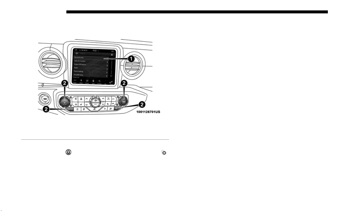
566 MULTIMEDIA
Customer Programmable Features — Uconnect 4C/
4C NAV Settings
Uconnect 4C/4C NAV Touchscreen and Faceplate Buttons
Press the “Apps ” button, then press the “Settings ”
button on the touchscreen to display the menu setting screen.
I
n this
mode the Uconnect system allows you to access all of
the available programmable features.
NOTE:
• O
nly one touchscreen area may be selected at a time.
• Dependi
ng on the vehicles options, feature settings may
vary.
When
making a selection, press the button on the touch-
screen to enter the desired mode. Once in the desired mode,
p
ress an
d release the preferred setting “option” until a
check-mark appears next to the setting, showing that setting
has been selected. Once the setting is complete, either press
the Back Arrow button on the touchscreen to return to the
previous menu, or press the “X” button on the touchscreen
to close out of the settings screen. Pressing the Up or Down
Arrow button on the right side of the screen will allow you
to toggle up or down through the available settings.
The following tables list the settings that may be found
within th
e Uconnect 4C/4C NAV radio, along with the
selectable options pertaining to each setting.
1 — Uconnect Buttons On The Touchscreen
2 — Uconnect Buttons On The Faceplate

MULTIMEDIA 567
Language
After pressing the “Language” button on the touchscreen, the following settings will be available:
Display
After pressing the “Display” button on the touchscreen, the following settings will be available:
Setting Name Selectable Options
Set Language English Español Français
NOTE:
When the “Set Language” feature is selected, you may select one of multiple languages (English / Français / Español) for all
display
nomenclature, including the trip functions and the navigation system (if equipped). Press the “Set Language” button
on the touchscreen, then press the desired language button on the touchscreen until a check-mark appears next to the
language, showing that setting has been selected.
Setting Name Selectable Options
Display Mode Manual Auto
Display Brightness With Headlights
O
N
+ -
NOTE:
To
make changes to the "Display Brightness with Headlights ON" setting, the headlights must be on and the interior dimmer
s
witch m
ust not be in the "party" or "parade" positions.
9

568 MULTIMEDIA
Display Brightness With Headlights
OFF
On Off
NOTE:
To make changes to the "Display Brightness with Headlights OFF" setting, the headlights must be off and the interior dimmer
s
witch m
ust not be in the "party" or "parade" positions.
Theme Set Theme
NOTE:
When in this display, you may select the theme for the display screen. To make your selection, press the "Set Theme" button
on the
touchscreen, then select the desired theme option button until a check-mark appears showing that the setting has been
selected.
Touchscreen Beep On Off
Control Screen Time-Out On Off
NOTE:
When the “Control Screen Time-Out” feature is selected, the Controls Screen will stay open for five seconds before the screen
times o
ut. With the feature deselected, the screen will stay open until it is manually closed.
Navigation Next Turn Pop-ups
Displaye
d in Cluster
On Off
NOTE:
When the “Navigation Next Turn Pop-ups Displayed in Cluster” feature is selected, the turn-by-turn directions will appear
i
n the
Instrument Cluster Display as the vehicle approaches a designated turn within a programmed route.
Phone Pop-ups Displayed in Cluster On Off
Setting Name Selectable Options

MULTIMEDIA 569
Units
After pressing the “Units” button on the touchscreen, the following settings will be available:
Voice
After pressing the “Voice” button on the touchscreen, the following settings will be available:
Setting Name Selectable Options
Units US Metric Custom
NOTE:
• T
he “Metric” option changes the instrument cluster display to metric units of measure.
• The “C
ustom” option allows setting the “Fuel Consumption” (L/100km, or km/L), “Pressure” (kPa, or bar), and
“Tempe
rature” (°C or °F) units of measure independently.
Setting Name Selectable Options
Voice Response Length Brief Detailed
Show Command List Always With Help Never
9

570 MULTIMEDIA
Clock
After pressing the “Clock” button on the touchscreen, the following settings will be available:
Setting Name Selectable Options
Sync Time With GPS — If Equipped On Off
Set Time Hours + -
NOTE:
The “Set Time Hours” feature will allow you to adjust the hours. The “Sync time with GPS” button on the touchscreen must
be unch
ecked.
Set Time Minutes + -
NOTE:
The “Set Time Minutes” feature will allow you to adjust the minutes. The “Sync time with GPS” button on the touchscreen
must be
unchecked.
Time Format 12hrs 24hrs
Show Time in Status Bar — If
Equippe
d
On Off

MULTIMEDIA 571
Camera
After pressing the “Camera” button on the touchscreen, the following settings will be available:
Setting Name Selectable Options
ParkView Backup Camera Delay On Off
NOTE:
The “ParkView Backup Camera Delay” setting determines whether or not the screen will display the rear view image with
dynamic
grid lines for up to ten seconds after the vehicle is shifted out of REVERSE. This delay will be canceled if the
vehicle’s speed exceeds 8
mph (13 km/h), the transmission is shifted into PARK, or the ignition is switched to the OFF posi-
tion.
ParkView Backup Camera Active
Guide L
ines
On Off
NOTE:
The “ParkView Backup Camera Active Guide Lines” feature overlays the Rear Backup Camera image with active, or
d
ynamic,
grid lines to help illustrate the width of the vehicle and its project back up path, based on the steering wheel posi-
tion when the option is checked. A dashed center line overlay indicates the center of the vehicle to assist with parking or
a
ligning
to a hitch/receiver.
ParkView Backup Camera Fixed
Guide L
ines
On Off
9

572 MULTIMEDIA
Safety & Driving Assistance
After pressing the “Safety & Driving Assistance” button on the touchscreen, the following settings will be available:
Setting Name Selectable Options
Forward Collision Warning
— If Eq
uipped
Off Warning Only Warning & Braking
NOTE:
Applies brakes to slow the vehicle in case of potential forward collision, or applies brakes and a warning.
Forward Collision Warning
Sensiti
vity — If Equipped
Near Med Far
NOTE:
Sets the distance in which a Forward Collision Warning occurs.
ParkSense — If Equipped Sound Only Sound & Display
Rear ParkSense Volume Low Medium High
Blind Spot Alert — If
Equippe
d
Off Lights Lights & Chime
NOTE:
If your vehicle has experienced any damage in the area where the sensor is located, even if the fascia is not damaged, the
s
ensor
may have become misaligned. Take your vehicle to an authorized dealer to verify sensor alignment. A sensor that is
misaligned will result in the BSM not operating to specification.
Hill Start Assist On Off

MULTIMEDIA 573
Mirrors and Wipers
After pressing the “Mirrors and Wipers” button on the touchscreen, the following settings will be available:
Lights
After pressing the “Lights” button on the touchscreen, the following settings will be available:
Setting Name Selectable Options
Headlights With Wipers — If
Equippe
d
On Off
Setting Name Selectable Options
Headlight Off Delay
0 sec 30 sec
60 sec 90 sec
NOTE:
When this feature is selected, it allows the adjustment of the amount of time the headlights remain on after the engine is shut
off.
Dayti
me Running Lights On Off
NOTE:
When the “Daytime Running Light” feature is selected, the daytime running lights can be turned on or off. This feature is
only all
owed by law in the country of the vehicle purchase.
Flash Lights With Lock — If Equipped On Off
9

574 MULTIMEDIA
Doors & Locks
After pressing the “Doors & Locks” button on the touchscreen, the following settings will be available:
Interior Ambient Lights + -
NOTE:
The “Interior Ambient Lights” setting can also be adjusted by selecting any point on the scale between the “+” and “-”
buttons
on the touchscreen.
Auto Dim High Beams — If Equipped On Off
NOTE:
When the “Auto Dim High Beams” feature is selected, the high beam headlights activate/deactivate automatically under
certain
conditions.
Setting Name Selectable Options
Setting Name Selectable Options
Auto Door Locks — If
Equippe
d
On Off
NOTE:
When this feature is selected, all doors will lock automatically when the vehicle reaches a speed of 12 mph (20 km/h).
Auto Unlock On Exit On Off
NOTE:
When the “Auto Unlock On Exit” feature is selected, all doors will unlock when the vehicle is stopped, the transmission is
i
n the
PARK or NEUTRAL position, and the driver's door is opened.
Flash Lights With Lock On Off

MULTIMEDIA 575
Sound Horn With Lock — If
Equipped
Off 1st Press 2nd Press
Sound Horn With Remote
Start —
If Equipped
On Off
1st Press Of Key Fob Unlocks Driver Door All Doors
NOTE:
When "Driver Door" is selected with 1st Press Of Key Fob Unlocks, only the driver's door will unlock with the first press of
the key f
ob unlock button. You must press the key fob unlock button twice to unlock the passenger's doors. When "All Doors"
is selected for 1st Press Of Key Fob Unlocks, all doors will unlock on the first press of the key fob unlock button. If the vehicle
is programmed 1st Press Of Key Fob Unlocks “All Doors,” all doors will unlock, no matter which Passive Entry equipped
door handle is grasped. If 1st Press Of Key Fob Unlocks “Driver Door” is programmed, only the driver’s door will unlock
when the driver’s door is grasped. With Passive Entry, if 1st Press Of Key Fob Unlocks “Driver Door” is programmed,
touching the handle more than once will result in only the driver’s door opening. If “Driver Door” is selected, once the driver
door is opened, the interior door lock/unlock switch can be used to unlock all doors (or use key fob).
Passive Entry — If Equipped On Off
NOTE:
The “Passive Entry” feature allows you to lock and unlock the vehicles door(s) without having to push the key fob lock or
unlock b
uttons. To make your selection, press the “Passive Entry” button on the touchscreen, until a check-mark appears
next to the setting, showing that the setting has been selected.
Setting Name Selectable Options
9

576 MULTIMEDIA
Auto Comfort Systems — If Equipped
After pressing the “Auto-On Comfort Systems” button on the touchscreen, the following settings will be available:
Aux Switches — If Equipped
After pressing the “Aux Switches” button on the touchscreen, the following settings will be available:
Setting Name Selectable Options
Auto-On Driver Heated Seat
& Steer
ing Wheel With
Vehicle Start — If Equipped
Off Remote Start All Starts
NOTE:
When this feature is selected the driver’s heated seat and heated steering wheel will automatically turn on when tempera-
tures are below 40° F (4.4° C). When temperatures are above 80° F (26.7° C) the driver vented seat will turn on.
Setting Name Selectable Options
Aux 1-4
Type Latching Momentary
Power Source Battery Ignition
Recalled Last State
NOTE:
Holding last state conditions are met when switch type is set to latching and power source is set to ignition.

MULTIMEDIA 577
Engine Off Options
After pressing the “Engine Off Options” button on the touchscreen, the following settings will be available:
Audio
After pressing the “Audio” button on the touchscreen, the following settings will be available:
Setting Name Selectable Options
Doors On Engine Off Power Delay + -
Doors Off Engine Off Power Delay + -
Headlight Off Delay + -
Setting Name Selectable Options
Balance/Fade Speaker Icon
NOTE:
When in this display you may adjust the “Balance/Fade” of the audio by pressing and dragging the “Speaker Icon” toward
any loca
tion in the box.
Equalizer Bass Mid Treble
NOTE:
When in this display you may adjust the “Bass”, “Mid”, and “Treble” settings. Adjust the settings with the “+” and “–”
setting
buttons on the touchscreen or by selecting any point on the scale between the “+” and “–” buttons on the touchscreen.
Bass/Mid/Treble also allow you to simply slide your finger up or down to change the setting as well as press directly on the
desired setting.
9

578 MULTIMEDIA
Phone
After pressing the “Phone/Bluetooth” button on the touchscreen, the following settings will be available:
Speed Adjusted
Volume
Off 1 2 3
A
UX Volume Offset —
If Equi
pped
+ -
NOTE:
This feature provides the ability to tune the audio level for portable devices connected through the AUX input.
Setting Name Selectable Options
Setting Name Selectable Options
Do Not Disturb Do Not Disturb Options
Paired Phones And Audio Devices List Of Paired Phones And Audio Devices
NOTE:
This feature shows which phones and audio devices are paired to the Phone/Bluetooth system. For further information, refer
to the
Uconnect Owner’s Manual Supplement.
Phone Pop-ups Displayed In Cluster On Off

MULTIMEDIA 579
SiriusXM Setup — If Equipped
After pressing the “SiriusXM Setup” button on the touchscreen, the following settings will be available:
Setting Name Selectable Options
Channel Skip List Of Channels
NOTE:
SiriusXM can be programmed to designate a group of channels that are the most desirable to listen to or to exclude undesir-
able channels while scanning. This feature allows you to select the channels you would like to skip.
Subscription Info Sirius ID
NOTE:
New vehicle purchasers or lessees will receive a free limited time subscription to SiriusXM Satellite Radio with your radio.
Fo
llowing
the expiration of the free services, it will be necessary to access the information on the Subscription Information
screen to re-subscribe.
1. Press the “Subscription Info” button on the touchscreen to access the Subscription Information screen.
2. Writ
e down the Sirius ID numbers for your receiver. To reactivate your service, either call the number listed on the screen
or vis
it the provider online.
SiriusXM Travel Link is a separate subscription.
9

580 MULTIMEDIA
Reset
After pressing the “Reset” button on the touchscreen, the following settings will be available:
Setting Name Selectable Options
Reset App Drawer OK Cancel
Restore Apps Back Next
NOTE:
Restoring Apps will delete all installed apps. This feature is used if there is an issue using or installing apps. To restore apps,
press t
he “Next” button in the pop-up screen. Then Press “Yes” on the confirmation screen. To keep installed apps, press
“Cancel.”
Restore Settings OK Cancel
NOTE:
When the “Restore Settings” feature is selected it will reset all settings to their default settings.
Clear Personal Data Yes Cancel
NOTE:
When the “Clear Personal Data” feature is selected it will remove all personal data including Bluetooth devices and presets.

MULTIMEDIA 581
System Information
After pressing the “System Information” button on the touchscreen, the following settings will be available:
Setting Name Selectable Options
Software Licenses Software Information Screen
NOTE:
When this feature is selected, a “Licensing Information” screen will appear, displaying a licensing information website for
the rad
io.
Map Update Download System Information To USB Generate Request Code
NOTE:
The “Download System Information To USB” will create a special USB required for Map updates of the radio. Whereas the
“Genera
te Request Code” will display a code for the user to input online when downloading the maps.
9
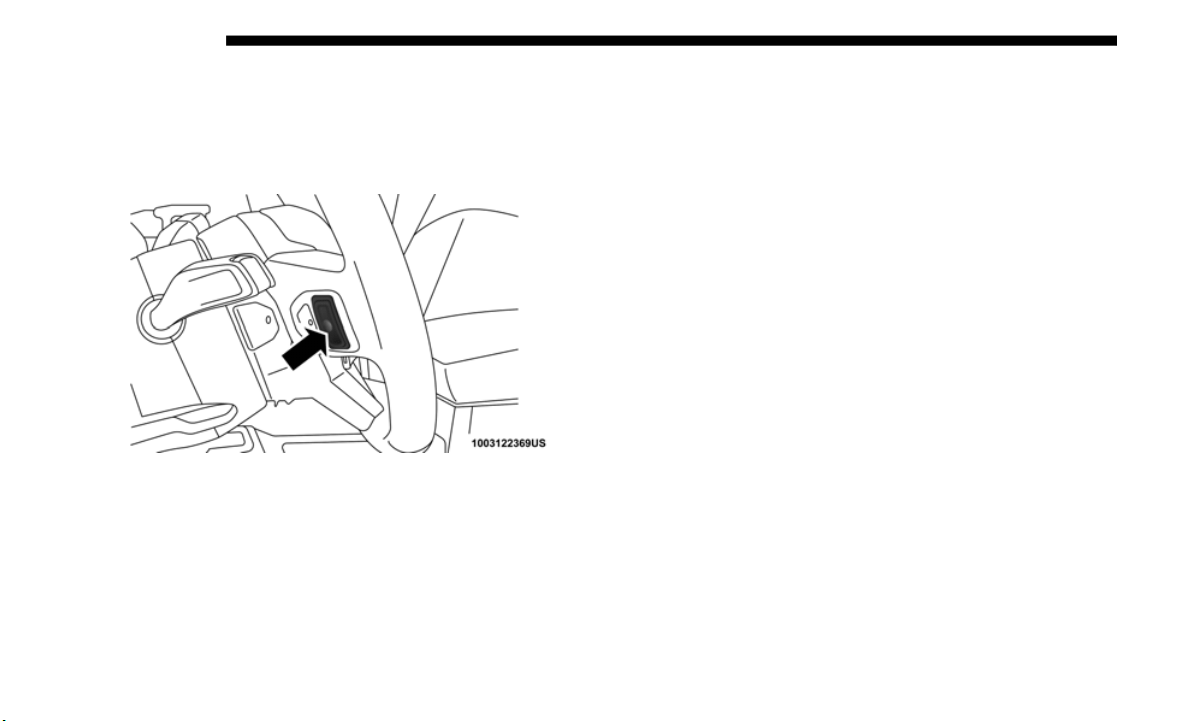
582 MULTIMEDIA
STEERING WHEEL AUDIO CONTROLS
The remote sound system controls are located on the rear
surface of the steering wheel. Reach behind the wheel to
access the switches.
Audio Controls (Back View Of Steering Wheel)
The right-hand control is a rocker-type switch with a
push-but
ton in the center and controls the volume and mode
of the sound system. Pushing the top of the rocker switch
increases the volume, and pushing the bottom of the rocker
switch decreases the volume.
Pushing the center button will make the radio switch
between t
he various modes available (AM/FM/SAT/CD/
USB/AUX, etc.).
The left-hand control is a rocker-type switch with a
push-but
ton in the center. The function of the left-hand
control is different depending on which mode you are in.
The following describes the left-hand control operation in
each mod
e.
Radio Operation
Pushing the top of the switch will “Seek” up for the next
listenable station and pushing the bottom of the switch will
“Seek” down for the next listenable station.
The button located in the center of the left-hand control will
tune to
the next preset station that you have programmed in
the radio preset button.
Media Mode
Pushing the top of the switch once goes to the next track on
the selected media (AUX/USB/Bluetooth). Pushing the
bottom of the switch once goes to the beginning of the
current track, or to the beginning of the previous track if it is
within eight seconds after the current track begins to play.
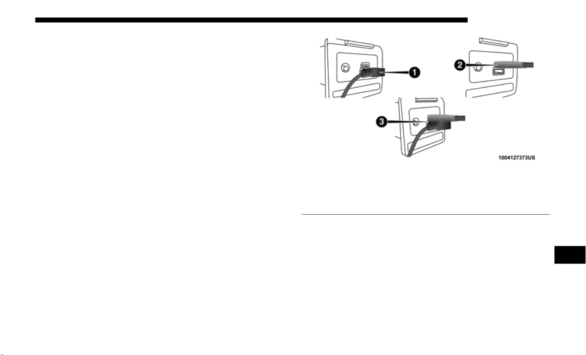
MULTIMEDIA 583
AUX/USB/MP3 CONTROL — IF EQUIPPED
The Media Hub is located on the Instrument Panel, below the
Climate Controls. Behind the Media Hub access door
contains one AUX port, a Type C USB Port and one standard
USB Port. Both USB Ports allow you to play music from
iPod/MP3 players or USB devices through your vehicle’s
sound system.
The Smart Charging USB ports provide power to your device
up to an
hour after the vehicle is turned off.
NOTE:
• T
he Type C USB port is the primary media port for the
radio.
Two devices can be plugged in at the same time and
both ports provide charging capabilities, but only one port
can transfer data to the head unit at a time.
• Both ports share a single data connection. However, the
user ca
nnot switch between Type A or Type C.
For example, if a device is plugged into the Type A USB port
and anot
her device is plugged into the Type C port, connec-
tion to the Type A port will be lost. Alternatively, if a device
i
s plugged
into the Type C port and another device is
plugged into the Type A port, the Type C device maintains
primary connection.
USB Connection
1 — Type A Plugged In
2 — Type C Plugged In
3 — Type A And Type C Plugged In
9
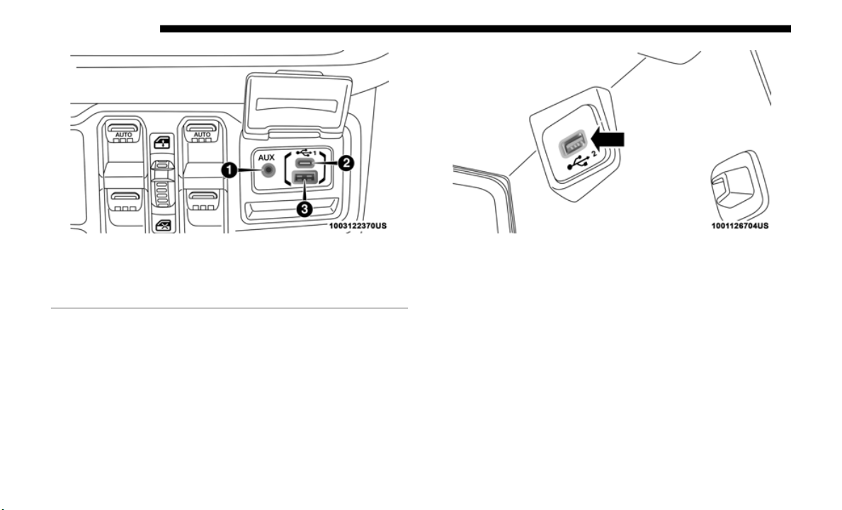
584 MULTIMEDIA
Media Hub
Located inside the center console, a second USB Port allows
you to pl
ay music from iPod/MP3 players or USB devices
through your vehicle’s sound system.
Center Console USB
A third and fourth USB Ports are located behind the center
console,
above the Power Inverter. One is a charge only port,
and can only charge USB devices. The other USB Port allows
you to play music from iPod/MP3 players or USB devices
through your vehicle’s sound system.
1 — AUX Port
2 — Type C USB Port
3 — Type A USB Port
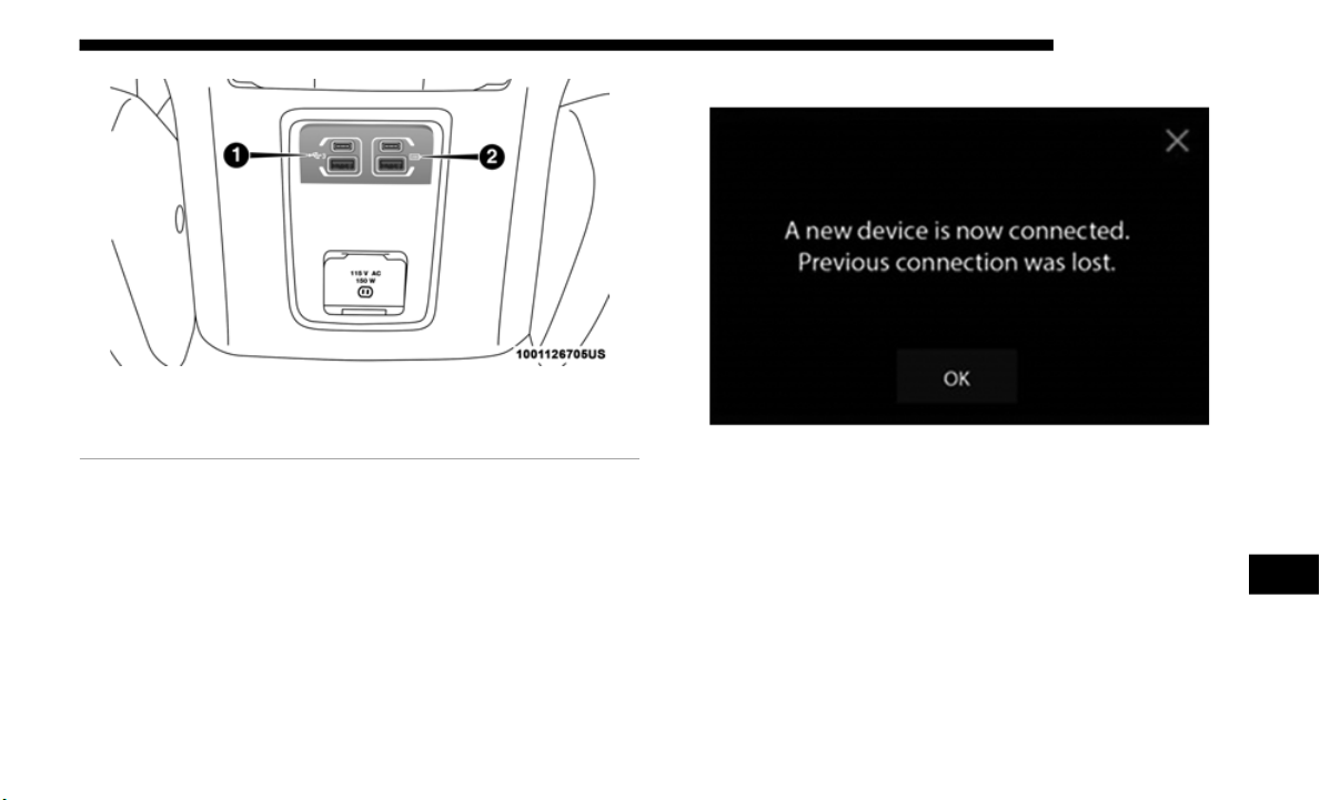
MULTIMEDIA 585
USB On The Back Of The Center Console
Device Plugged In Message Screen
1 — Type C And Standard USB Ports
2 — Type C And Standard Charge Only USB Ports
9
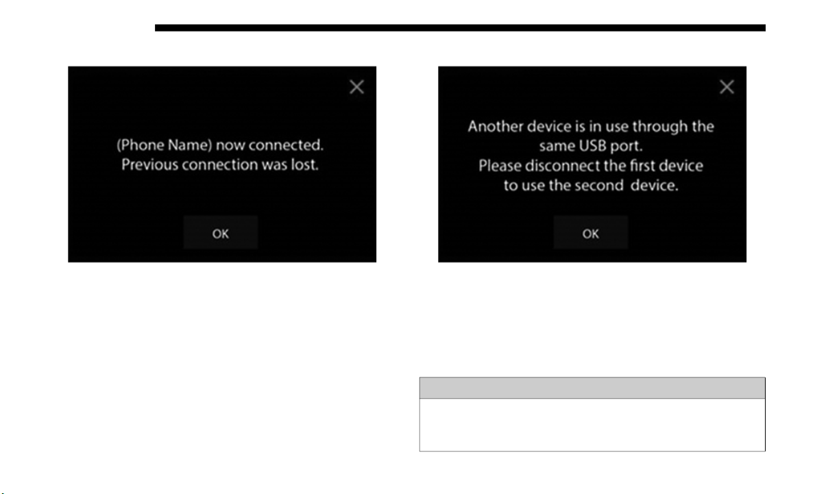
586 MULTIMEDIA
Phone Plugged In Message Screen Phone or USB Plugged In Message Screen
NOTE:
Plugging in a phone or another USB device may cause the
c
o
nnecti
on to a previous device to be lost.
WARNING!
Do not plug in or remove the iPod or external device
while dr
iving. Failure to follow this warning could result
in a collision.

MULTIMEDIA 587
RADIO OPERATION AND MOBILE PHONES
Under certain conditions, the mobile phone being on in your
vehicle can cause erratic or noisy performance from your
radio. This condition may be lessened or eliminated by relo
-
cating the mobile phone antenna. This condition is not
harmful
to the radio. If your radio performance does not
satisfactorily “clear” by the repositioning of the antenna, it is
recommended that the radio volume be turned down or off
during mobile phone operation when not using Uconnect (if
equipped).
Regulatory And Safety Information
USA/CANADA
Exposure to Radio Frequency Radiation
The radiated output power of the internal wireless radio is
far bel
ow the FCC and IC radio frequency exposure limits.
Nevertheless, the wireless radio will be used in such a
manner that the radio is 8
in (20 cm) or further from the
human b
ody.
The internal wireless radio operates within guidelines found
in radi
o frequency safety standards and recommendations,
which reflect the consensus of the scientific community.
The radio manufacturer believes the internal wireless radio
is safe
for use by consumers. The level of energy emitted is
far less than the electromagnetic energy emitted by wireless
devices such as mobile phones. However, the use of wireless
radios may be restricted in some situations or environments,
such as aboard airplanes. If you are unsure of restrictions,
you are encouraged to ask for authorization before turning
on the wireless radio.
The following regulatory statement applies to all Radio
Frequenc
y (RF) devices equipped in this vehicle:
This device complies with Part 15 of the FCC Rules and with
Industr
y Canada license-exempt RSS standard(s). Operation
is subject to the following two conditions:
1. This device may not cause harmful interference, and
2. This
device must accept any interference received,
includ
ing interference that may cause undesired opera-
tion.
NOTE:
Changes or modifications not expressly approved by the
p
arty re
sponsible for compliance could void the user’s
authority to operate the equipment.
9
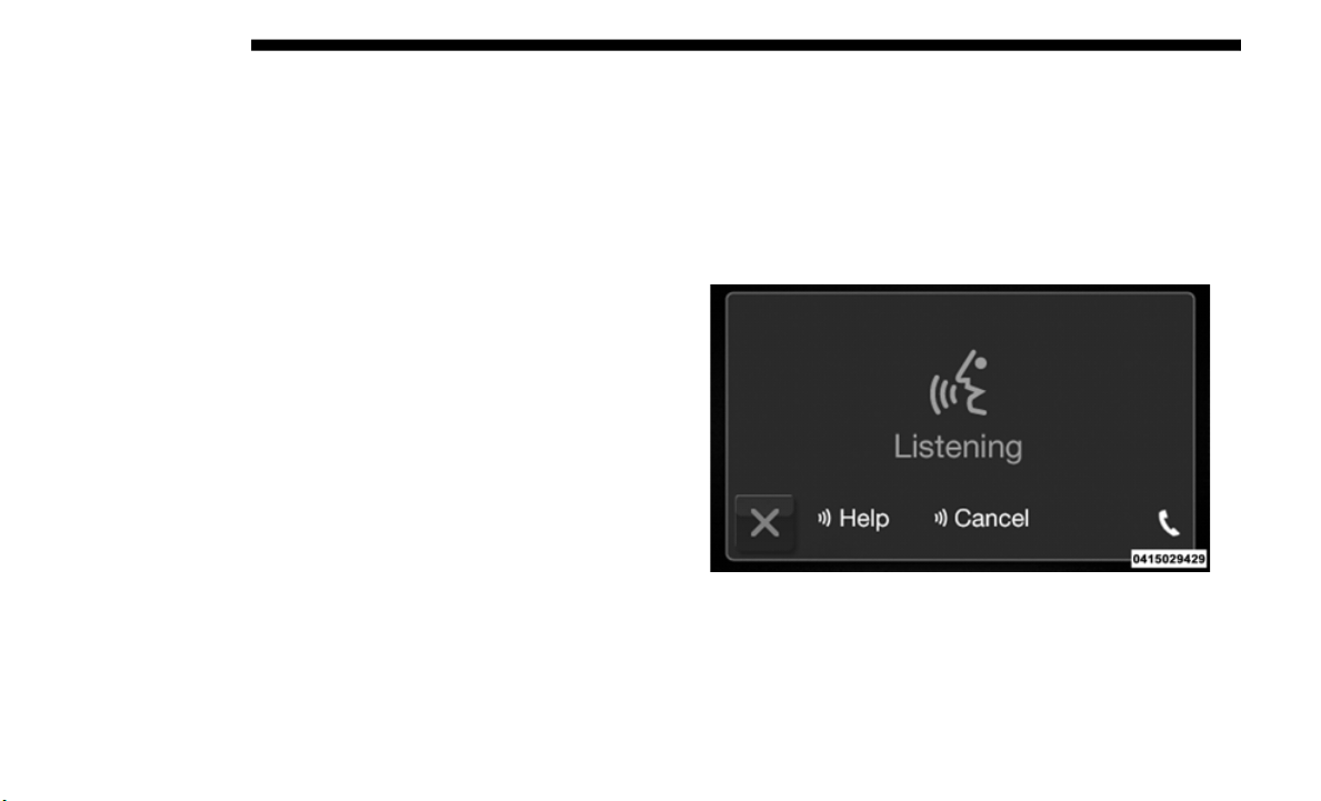
588 MULTIMEDIA
NOTE:
• This equipment has been tested and found to comply with
the li
mits for a Class B digital device, pursuant to Part 15
of the FCC Rules. These limits are designed to provide
reasonable protection against harmful interference in a
residential installation. This equipment generates, uses
and can radiate radio frequency energy and, if not
installed and used in accordance with the instructions,
may cause harmful interference to radio communications.
However, there is no guarantee that interference will not
occur in a particular installation.
• If this equipment does cause harmful interference to radio
or tel
evision reception, which can be determined by
turning the equipment off and on, the user is encouraged
to try to correct the interference by one or more of the
following measures:
1. Increase the separation between the equipment and
receiv
er.
2. Consult an authorized dealer or an experienced radio
techni
cian for help.
UCONNECT VOICE RECOGNITION QUICK TIPS
Introducing Uconnect
Start using Uconnect Voice Recognition with these helpful
quick tips. It provides the key Voice Commands and tips you
need to know to control your Uconnect 3, Uconnect 4, or
Uconnect 4C/4C NAV system.
Uconnect 3
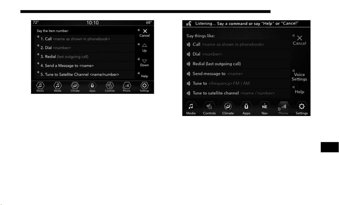
MULTIMEDIA 589
Uconnect 4
Uconnect 4C/4C NAV
If you see the NAV icon on the bottom bar or in the Apps
menus of
your 8.4-inch touchscreen, you have the Uconnect
4C NAV system. If not, you have a Uconnect 4C with 8.4-inch
display system.
9
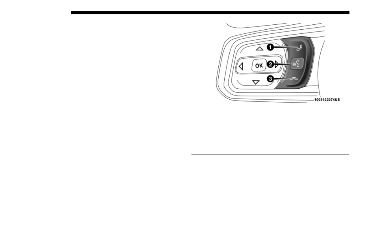
590 MULTIMEDIA
Get Started
All you need to control your Uconnect system with your
voice are the buttons on your steering wheel.
1. Visit UconnectPhone.com to ch
eck mobile device and
feature compatibility and to find phone pairing instruc-
tions.
2. R
educe background noise. Wind and passenger conver-
sations
are examples of noise that may impact recogni-
tion.
3. S
peak clearly at a normal pace and volume while facing
straight
ahead. The microphone is positioned on the rear-
view mirror and aimed at the driver.
4. E
ach time you give a Voice Command, you must first
push ei
ther the Voice Recognition (VR) or Phone button,
wait until after the beep, then say your Voice Command.
5. You can interrupt the help message or system prompts by
pushing
the VR or Phone button and saying a Voice
Command from current category.
Uconnect Voice Command Buttons — If Equipped
1 — Push To Initiate Or To Answer A Phone Call, Send Or Receive A
Text
2 — For All Radios: Push To Begin Radio Or Media Functions. For
8.4-inch
Displays Only: Push To Begin Navigation, Apps And Climate
Functions.
3 — Push To End Call

MULTIMEDIA 591
Basic Voice Commands
The basic Voice Commands below can be given at any point
while using your Uconnect system.
Push the VR button . After the beep, say:
• “C
ancel” to st
op a current voice session
• “Help” to hear a list of suggested Voice Commands
• “Repe
at” to li
sten to the system prompts again
Notice the visual cues that inform you of your voice recogni-
tion system’s status. Cues appear on the touchscreen.
Radio
Use your voice to quickly get to the AM, FM or SiriusXM
Satellite Radio stations you would like to hear. (Subscription
or included SiriusXM Satellite Radio trial required.)
Push the VR button . After the beep, say:
• “Tune to ninety-
five-point-five FM”
• “Tune to Satellite Channel Hits 1
”
TIP:
At any time, if you are not sure of what to say or want to
l
earn a
Voice Command, push the VR button and say
“H
elp.” The system provides you with a list of commands.
Uconnec
t 3 Radio
9
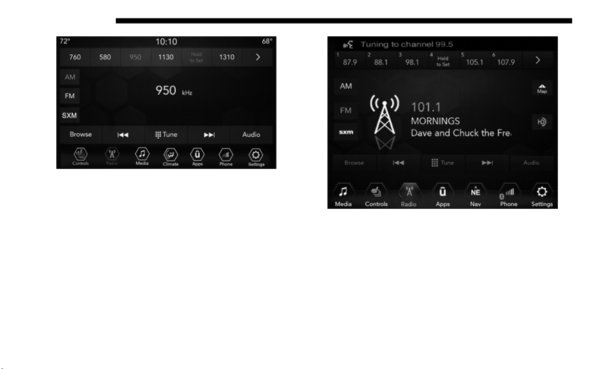
592 MULTIMEDIA
Uconnect 4 Radio
Uconnect 4C/4C NAV Radio
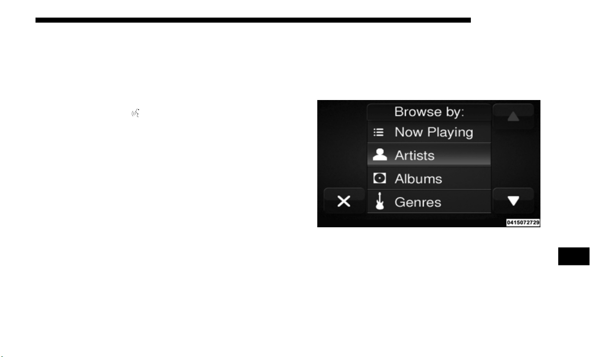
MULTIMEDIA 593
Media
Uconnect offers connections via USB, Bluetooth and auxil-
iary ports (if equipped). Voice operation is only available for
connecte
d USB and AUX devices. (Remote CD player
optional and not available on all vehicles.)
Push the VR button . After the beep, say one of the
following commands and follow the prompts to switch your
media so
urce or choose an artist.
• “Change source to Blueto
oth”
• “Change source to AUX”
• “C
hange source to USB”
• “P
lay artist Beethoven”; “Play alb
um Greatest Hits”;
“Play song Moonlight Sonata”; “Play genre Classical”
TIP:
Press the Browse button on the touchscreen to see all of the
music on
your USB device. Your Voice Command must
match exactly how the artist, album, song and genre infor
-
mation is displayed.
Uconnect 3 Media
9
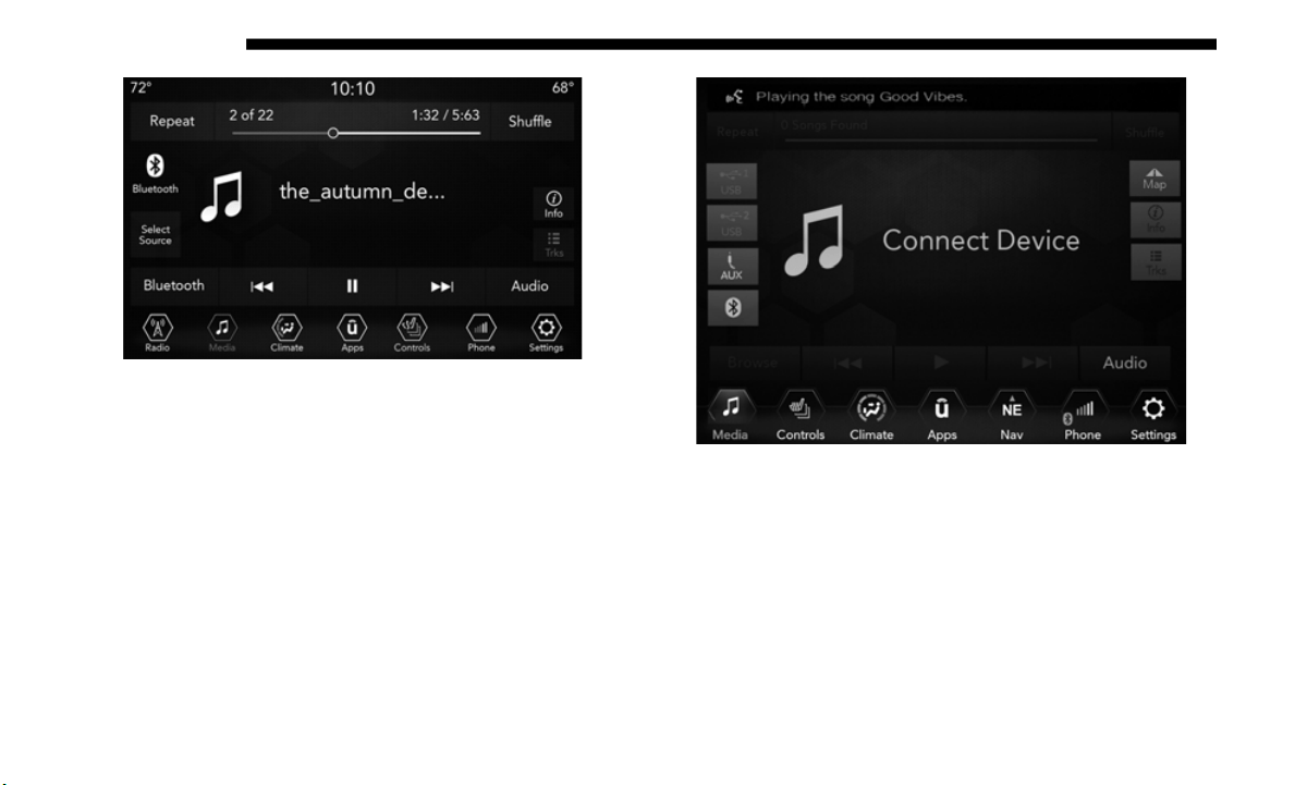
594 MULTIMEDIA
Uconnect 4 Media
Uconnect 4C/4C NAV Media
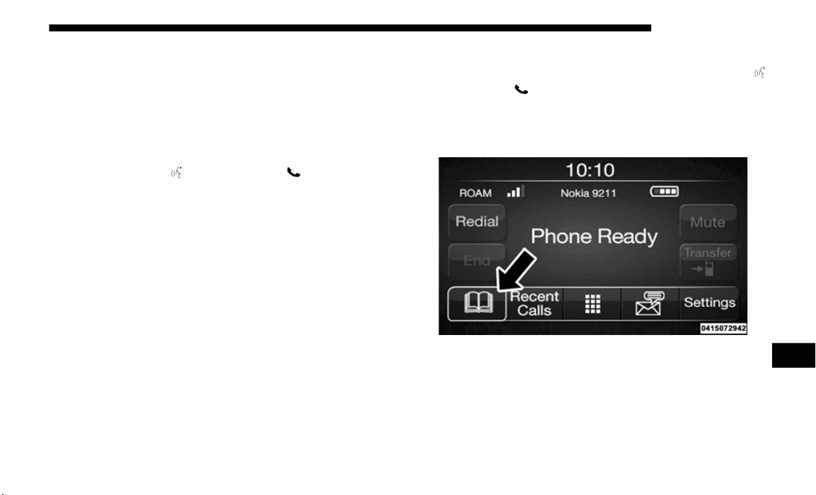
MULTIMEDIA 595
Phone
Making and answering hands-free phone calls is easy with
Uconnect. When the Phonebook button is illuminated on
your touchscreen, your system is ready. Check
Uconnect-
Phone.com for mobile phone compatibility and pairing
instructions.
Push the VR button or Phone button . After the beep,
say one of the following commands:
• “C
all John Smith”
• “Dial
123-456-7890 and follow the system prompts”
• “Redi
al (call previous outgoing phone number)”
• “Call
back (call
previous incoming phone number)”
TIP:
When providing a Voice Command, push the VR button
or Phone button and say “Call,” then pronounce the name
exactly as it appears in your phone book. When a contact has
multipl
e phone numbers, you can say “Call John Smith
work.”
Uconnect 3 Phone
9
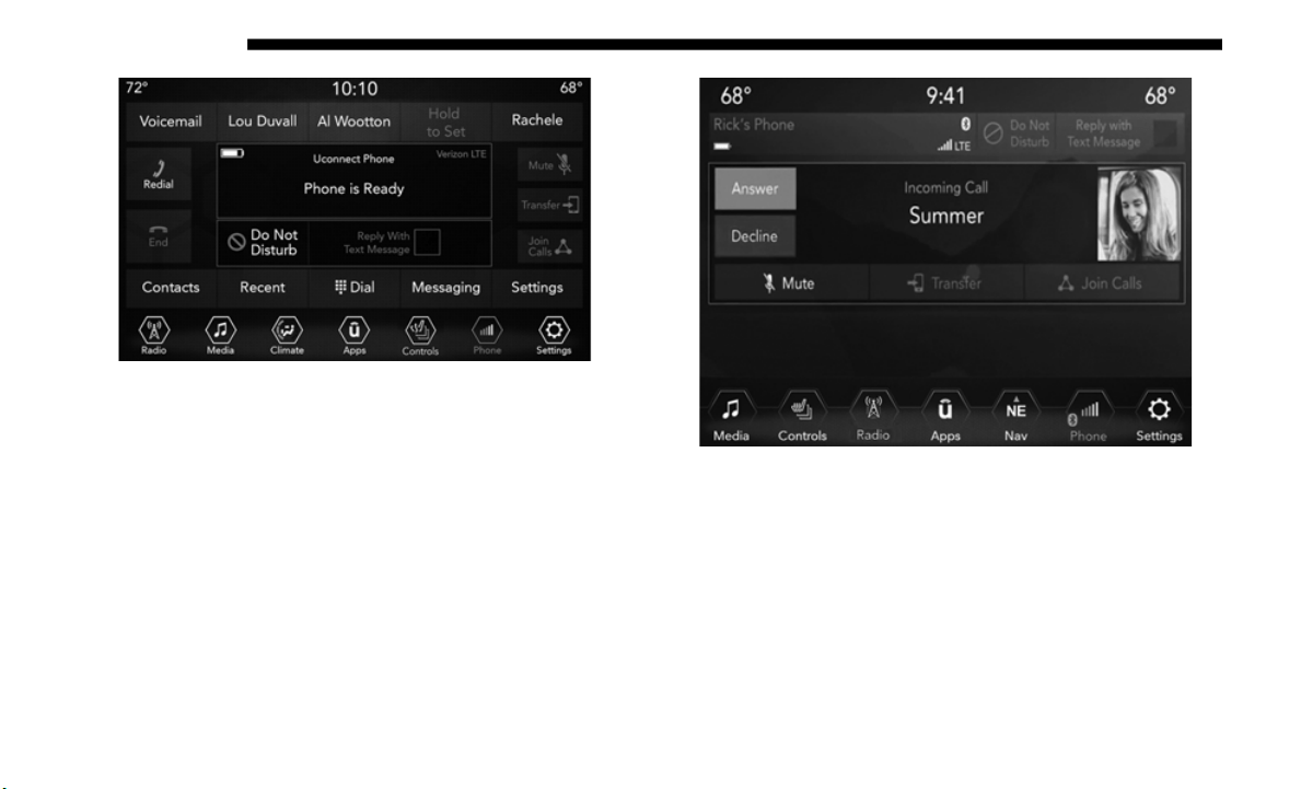
596 MULTIMEDIA
Uconnect 4 Phone
Uconnect 4C/4C NAV Phone

MULTIMEDIA 597
Voice Text Reply
Uconnect announces incoming text messages. Push the VR
button or Phone button (if enabled) and say “Listen.”
(M
ust have compatible mobile phone paired to Uconnect
system.)
1.
Once an incoming text message is read to you, push the
VR butt
on or Phone button (if enabled). After the
beep, say: “R
eply.”
2. L
isten to the Uconnect prompts. After the beep, repeat
one of
the pre-defined messages and follow the system
prompts.
NOTE:
Only use the numbering listed, otherwise the system does
not tran
spose the message.
TIP:
Your mobile phone must have the full implementation of the
Message A
ccess Profile (MAP) to take advantage of this
feature. For details about MAP, visit
UconnectPhone.com.
PRE-DEFINED VOICE TEXT REPLY RESPONSES
Yes. Stuck in traffic. See you later.
No. Start without me. I’ll be late.
Okay. Where are you? I will be 5 <or 10,
1
5, 20,
25, 30, 45,
60> minutes late.
Call me. Are you there yet?
I’ll call you later. I need directions. See you in 5 <or
1
0, 15,
20, 25, 30,
45, 60> minutes.
I’m on my way.
Can’t talk right
now.
I’m los
t. Thanks.
9
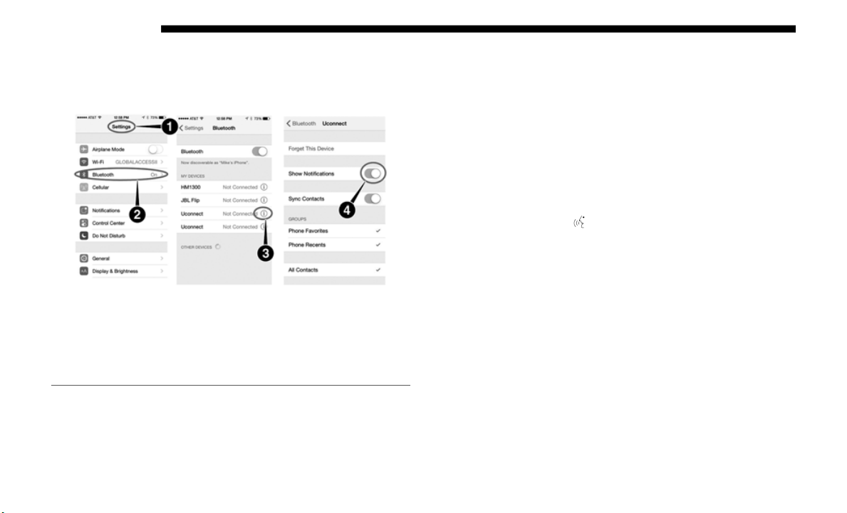
598 MULTIMEDIA
Apple iPhone iOS 6 or later supports reading incoming text
messages only. To enable this feature on your Apple iPhone,
follow these four simple steps:
iPhone Notification Settings
TIP:
Voice Text Reply is not compatible with iPhone, but if your
vehicle
is equipped with Siri Eyes Free, you can use your
voice to send a text message.
Climate
Too hot? Too cold? Adjust vehicle temperatures hands-free
and keep everyone comfortable while you keep moving
ahead. (If vehicle is equipped with climate control.)
Push the VR button . After the beep, say one of the
following commands:
• “S
et driver temperature to 70 degre
es”
• “Set passenger temperature to 70 degre
es”
1 — Select “Settings”
2 — Select “Bluetooth”
3 — Select The (i) For The Paired Vehicle
4 — Turn On “Show Notifications”
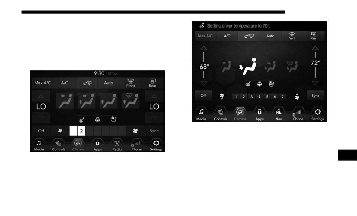
MULTIMEDIA 599
TIP:
Voice Command for Climate may only be used to adjust the
interior
temperature of your vehicle. Voice Command will
not work to adjust the heated seats or steering wheel if
equipped.
Uconnect 4 Climate
Uconnect 4C/4C NAV Climate
9
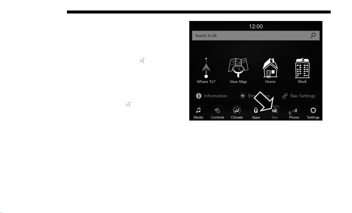
600 MULTIMEDIA
Navigation (4C NAV) — If Equipped
The Uconnect navigation feature helps you save time and
become more productive when you know exactly how to get
to where you want to go.
1. To enter a destination, push the VR button . After
the
beep, say: “Find addr
ess 800 Chrysler Drive Auburn
Hills, Michigan.”
2. Then follow the system prompts.
TIP:
To s
tart a POI search, push the VR button . After the beep,
say: “Fi
nd nearest coffee
shop.”
Uconnect 4C NAV Navigation
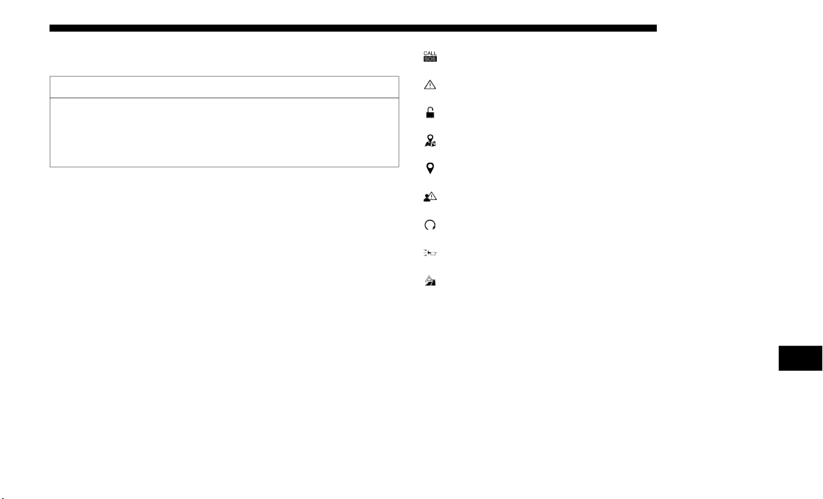
MULTIMEDIA 601
SiriusXM Guardian (4C/4C NAV) — If Equipped
NOTE:
Your vehicle may be transmitting data as authorized by the
subscri
ber.
An included trial and/or subscription is required to take
advanta
ge of the SiriusXM Guardian services in the next
section of this guide. To register with SiriusXM Guardian,
press the Apps button on the Uconnect 4C/4C NAV touch
-
screen to get started.
NOTE:
SiriusXM Guardian is available only on equipped vehicles
p
urchas
ed within the continental United States, Alaska,
Hawaii and Canada. Services can only be used where
coverage is available; see coverage map for details.
SOS Call
Theft Alarm Notification
Remote Door Lock/Unlock
Send & Go
Vehicle Finder
Stolen Vehicle Assistance
Remote Vehicle Start**
Remote Horn & Lights
Roadside Assistance Call
Vehicle Health Reports**
Vehicle Health Alert**
Performance Pages Plus**
**If vehicle is equipped.
CAUTION!
Some SiriusXM Guardian services, including SOS Call
a
nd Road
side Assistance Call will NOT work without an
operable LTE (voice/data) or 3G or 4G (data) network
connection compatible with your device.
9

602 MULTIMEDIA
Register (4C/4C NAV)
To unlock the full potential of SiriusXM Guardian in your
vehicle, you must activate your SiriusXM Guardian services.
1. Press the Apps icon on the bottom of your in-vehicle
touchsc
reen.
2. S
elect the Activate Services icon from your list of apps.
3
. Selec
t “Customer Care” to speak with a SiriusXM
Guardia
n Customer Care agent who will activate services
in your vehicle, or select “Enter Email” to activate on the
web.
• U.S. residents visit: www.sirius
xm.com/guardian.
• Canadian residents visit: www.sirius
xm.ca/guardian.
Vehicle Health Report/Alert (4C/4C NAV)
Your vehicle will send you a monthly email report, which
summarizes the performance of your vehicle’s key systems
so you can stay on top of your vehicle’s maintenance needs
if you are registered for SiriusXM Guardian. Your vehicle
will also send you Vehicle Health Alerts when it detects
issues with its key systems that need your attention. For
further information, refer to your Uconnect Owner’s Manual
Supplement.
Mobile App (4C/4C NAV)
You’re only a few steps away from using remote commands
and sending a destination from your phone to your vehicle.
Mobile App
To use the Uconnect Mobile App:
1. Once you have registered your SiriusXM Guardian
service
s, download the Uconnect App to your mobile
device. Use your Owner Account login and password to
open the app.
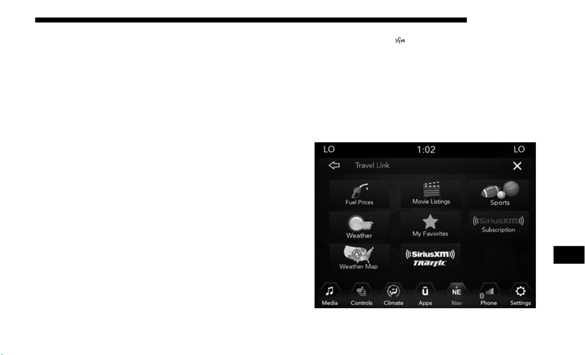
MULTIMEDIA 603
2. Once on the “Remote” screen, you can begin using
Remote Door Lock/Unlock, Remote Vehicle Start, and
activate your horn and lights remotely, if equipped.
3. Press the “Location” button on the bottom menu bar of
the app
to bring up a map to locate your vehicle or send a
location to your Uconnect Navigation using Vehicle
Finder and Send & Go , if equipped.
4. Press the “Settings” side menu in the upper left corner of
the app
to bring up app settings.
NOTE:
For further information please visit DriveUconnect.com
(U.S. Residents) or DriveUconnect.ca (Canadian Residents).
SiriusXM Travel Link (4C NAV)
Need to find a gas station, view local movie listings, check a
sports score or the 5 - day weather forecast? SiriusXM Travel
Link is a suite of services that brings a wealth of information
right to your Uconnect 4C NAV system. (Not available for
Uconnect 4 system.)
Push the VR button . After the beep, say one of the
following commands:
• “S
how fuel prices”
• “Show 5
- day weather forecast”
• “Show e
xtended weather”
TIP:
Traf
fic alerts are not accessible with Voice Command.
SiriusXM Travel Link
9
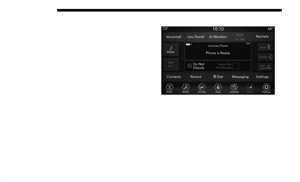
604 MULTIMEDIA
Siri Eyes Free — If Equipped
Siri lets you use your voice to send text messages, select
media, place phone calls and much more. Siri uses your
natural language to understand what you mean and
responds back to confirm your requests. The system is
designed to keep your eyes on the road and your hands on
the wheel by letting Siri help you perform useful tasks.
To enable Siri, push and hold, then release the Uconnect
Voice Re
cognition (VR) button on the steering wheel. After
you hear a double beep you can ask Siri to play podcasts and
music, get directions, read text messages and many other
useful requests.
Uconnect 4 Siri Eyes Free Available
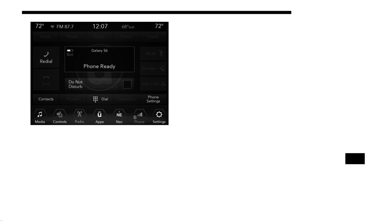
MULTIMEDIA 605
Uconnect 4C/4C NAV With 8.4–inch Siri Eyes Free Available
Using Do Not Disturb
With Do Not Disturb, you can disable notifications from
incoming calls and texts, allowing you to keep your eyes on
the road and hands on the wheel. For your convenience,
there is a counter display to keep track of your missed calls
and text messages while you were using Do Not Disturb.
Do Not Disturb can automatically reply with a text message,
a call,
or both, when declining an incoming call and send it
to voicemail.
Automatic reply messages can be:
• “I am driving right now, I will get back to you shortly.”
• Create
a custom auto reply message up to 160 characters.
While i
n Do Not Disturb, Conference Call can be selected so
you can still place a second call without being interrupted by
incoming calls.
NOTE:
• Only the beginning of your custom message will be seen
on the
touchscreen.
• Reply with text message is not compatible with iPhones.
• Auto re
ply with text message is only available on phones
that su
pport Bluetooth MAP.
9
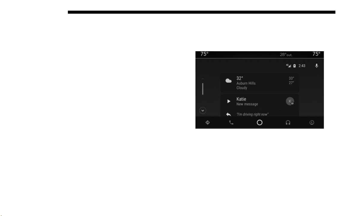
606 MULTIMEDIA
Android Auto — If Equipped
NOTE:
Feature availability depends on your carrier and mobile
phone ma
nufacturer. Some Android Auto features may or
may not b
e available in every region and/or language.
Android Auto allows you to use your voice to interact with
A
n
droid’s
best-in-class speech technology through your
vehicle’s voice recognition system, and use your smart
-
phone’s data plan to project your Android powered smart-
phone and a number of its apps onto your Uconnect
t
ouchscr
een. Connect your Android 5.0 (Lollipop), or higher,
to one of the media USB ports, using the factory-provided
USB cable, and press the new Android Auto icon that
replaces your “Phone” icon on the main menu bar to begin
Android Auto. Push and hold the VR button on the steering
wheel, or press and hold the “Microphone” icon within
Android Auto, to activate Android’s VR, which recognizes
natural voice commands, to use a list of your smartphone’s
features:
• Maps
• Music
• Ph
one
• Te
xt Me
ssages
• Additio
nal Apps
Android
Auto On 7-inch Display
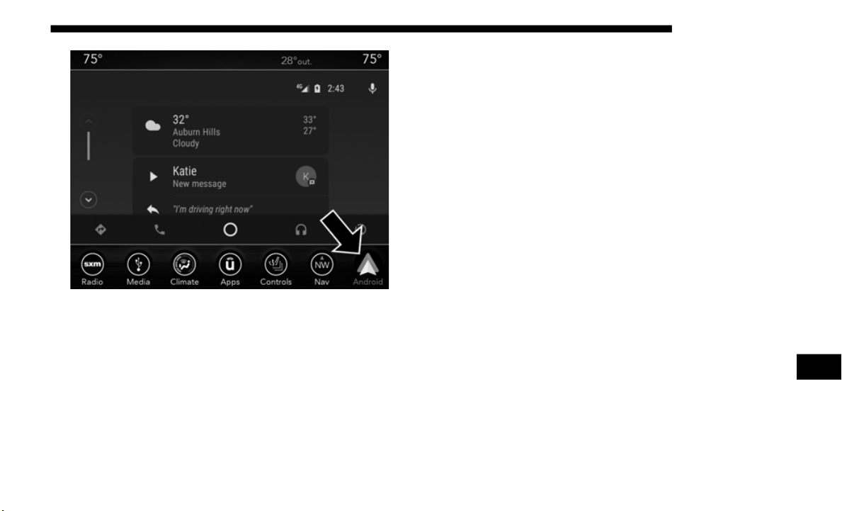
MULTIMEDIA 607
Android Auto On 8.4-inch Display
Refer to your Uconnect Owner’s Manual Supplement for
further
information.
NOTE:
Requires compatible smartphone running Android 5.0
L
ollipo
p or higher and download app on Google Play.
Android, Android Auto, and Google Play are trademarks of
Google Inc.
Apple CarPlay — If Equipped
NOTE:
Feature availability depends on your carrier and mobile
phone m
anufacturer. Some Apple CarPlay features may or
may not
be available in every region and/or language.
Apple CarPlay allows you to use your voice to interact with
S
i
ri th
rough your vehicle’s voice recognition system, and use
your smartphone’s data plan to project your iPhone and a
number of its apps onto your Uconnect touchscreen. Connect
your iPhone 5, or higher, to one of the media USB ports,
using the factory-provided Lightning cable, and press the
new CarPlay icon that replaces your “Phone” icon on the
main menu bar to begin Apple CarPlay. Push and hold the
VR button on the steering wheel, or press and hold the
“Home” button within Apple CarPlay, to activate Siri, which
recognizes natural voice commands to use a list of your
iPhone’s features:
• Phone
• Music
• M
essage
s
• Maps
• Ad
diti
onal Apps
9
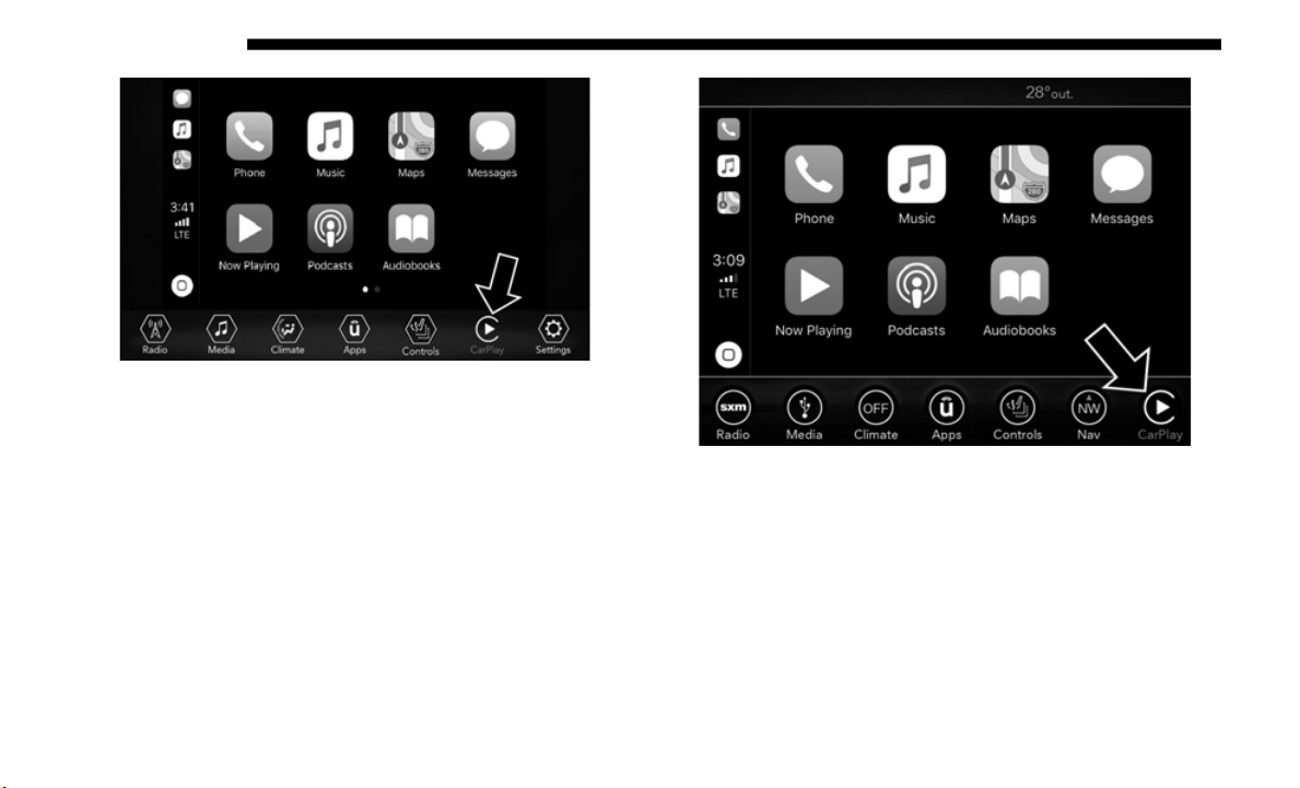
608 MULTIMEDIA
Apple CarPlay On 7-inch Display
Apple CarPlay On 8.4-inch Display
Refer to your Uconnect Owner’s Manual Supplement for
further
information.
NOTE:
Requires compatible iPhone. See dealer for phone
c
ompatib
ility. Data plan rates apply. Vehicle user interface is a
product
of Apple. Apple CarPlay is a trademark of Apple Inc.
iPhone is a trademark of Apple Inc., registered in the US and other
countries.
Apple terms of use and privacy statements apply.

MULTIMEDIA 609
General Information
The following regulatory statement applies to all Radio
Frequency (RF) devices equipped in this vehicle:
This device complies with Part 15 of the FCC Rules and with
Industr
y Canada license-exempt RSS standard(s). Operation
is subject to the following two conditions:
1. This device may not cause harmful interference, and
2. This
device must accept any interference received,
includ
ing interference that may cause undesired opera-
tion.
NOTE:
Changes or modifications not expressly approved by the
p
arty re
sponsible for compliance could void the user’s
authority to operate the equipment.
Additional Information
© 2019 FCA US LLC. All rights reserved. Mopar and Ucon-
nect are registered trademarks and Mopar Owner Connect is
a trade
mark of FCA US LLC. Android is a trademark of
Google Inc. SiriusXM and all related marks and logos are
trademarks of SiriusXM Radio Inc.
Uconnect System Support:
• U
.S. residents visit www.Drive
Uconnect.com or call:
1-877-855-8400(24 hou
rs a day 7 days a week)
• Canadian residents visit www.Drive
Uconnect.ca or call:
1-800-465-2001(English
) or 1-800-387-9983(French)
SiriusXM Guardian services support:
• U.S. residents visit www.siriu
sxm.com/guardian or call:
1-844-796-4827
• C
anadian residents visit www.siriu
sxm.ca/guardian or
call: 1-877-324-9091
9

610 MULTIMEDIA
CD/DVD DISC MAINTENANCE
To keep a CD/DVD in good condition, take the following
precautions:
• Handle the disc by its edge; avoid touching the surface.
• If the
disc is stained, clean the surface with a soft cloth,
wiping f
rom center to edge.
• Do not apply paper or tape to the disc; avoid scratching the
disc.
• D
o not use solvents such as benzene, thinner, cleaners, or
anti-s
tatic sprays.
• Store the disc in its case after playing.
• Do not
expose the disc to direct sunlight.
• Do not
store the disc where temperatures may become too
high.
NOT
E:
If you experience difficulty in playing a particular disc, it
m
ay be d
amaged (e.g., scratched, reflective coating removed,
a hair, moisture or dew on the disc), oversized, or have
protection encoding. Try a known good disc before consid
-
ering disc player service.

611
CUSTOMER ASSISTANCE
SUGGESTIONS FOR OBTAINING SERVICE FOR
YOUR VEHICLE
Prepare For The Appointment
If you are having warranty work done, be sure to have the
right papers with you. Take your warranty folder. All work
to be performed may not be covered by the warranty.
Discuss additional charges with the service manager. Keep a
maintenance log of your vehicle's service history. This can
often provide a clue to the current problem.
Prepare A List
Make a written list of your vehicle's problems or the specific
work you want done. If you've had an accident or work done
that is not on your maintenance log, let the service advisor
know.
Be Reasonable With Requests
If you list a number of items and you must have your vehicle
by the end of the day, discuss the situation with the service
advisor and list the items in order of priority. At many autho
-
rized dealers, you may obtain a rental vehicle at a minimal
daily ch
arge. If you need a rental, it is advisable to make
these arrangements when you call for an appointment.
IF YOU NEED ASSISTANCE
The manufacturer and its authorized dealer are vitally inter-
ested in your satisfaction. We want you to be happy with our
product
s and services.
Warranty service must be done by an authorized dealer. We
strongly
recommend that you take the vehicle to an autho-
rized dealer. They know your vehicle the best, and are most
c
oncern
ed that you get prompt and high quality service. The
manufacturer's authorized dealer have the facilities,
factory-trained technicians, special tools, and the latest infor
-
mation to ensure the vehicle is fixed correctly and in a timely
m
anner.
10

612 CUSTOMER ASSISTANCE
This is why you should always talk to an authorized dealer
service manager first. Most matters can be resolved with this
process.
• If for some reason you are still not satisfied, talk to the
general
manager or owner of the authorized dealer. They
want to know if you need assistance.
• If an authorized dealer is unable to resolve the concern,
you may
contact the manufacturer's customer center.
Any communication to the manufacturer's customer center
should
include the following information:
• Owner's name and address
• Owner's
telephone number (home and office)
• Author
ized dealer name
• Vehicl
e Identification Number (VIN)
• Vehicl
e delivery date and mileage
FCA US LLC Customer Center
P.O. Box 21–8004
Auburn Hills, MI 48321–8004
Phone: (877) 426-5337
FCA Canada Inc. Customer Center
P.O. Box 1621
Windsor, Ontario N9A 4H6
Phone: (800) 465-2001 English / (800) 387-9983 French
In Mexico Contact
Av. Prolongacion Paseo de la Reforma, 1240
Sante Fe C.P. 05109
Mexico, D. F.
In Mexico City: 800-505-1300
Outside Mexico City: +(52)55 50817568
Puerto Rico And U.S. Virgin Islands
FCA Caribbean LLC
P.O. Box 191857
San Juan 00919-1857
Phone: (877) 426-5337
Fax: (787) 782-3345

CUSTOMER ASSISTANCE 613
Customer Assistance For The Hearing Or Speech
Impaired (TDD/TTY)
To assist customers who have hearing difficulties, the manu-
facturer has installed special TDD (Telecommunication
Devices
for the Deaf) equipment at its customer center. Any
hearing or speech impaired customer, who has access to a
TDD or a conventional teletypewriter (TTY) in the United
States, can communicate with the manufacturer by dialing
1-800-380-CHRY.
Canadian residents with hearing difficulties that require
assista
nce can use the special needs relay service offered by
Bell Canada. For TTY teletypewriter users, dial 711 and for
Voice callers, dial 1-800-855-0511 to connect with a Bell Relay
Service operator.
Service Contract
You may have purchased a service contract for a vehicle to
help protect you from the high cost of unexpected repairs
after the manufacturer's New Vehicle Limited Warranty
expires. The manufacturer stands behind only the manufac
-
turer's service contracts. If you purchased a manufacturer's
s
ervice
contract, you will receive Plan Provisions and an
Owner Identification Card in the mail within three weeks of
the vehicle delivery date. If you have any questions about the
service contract, call the manufacturer's Service Contract
National Customer Hotline at 1-800-521-9922 (Canadian resi
-
dents, call (800) 465-2001 English / (800) 387-9983 French).
The manufacturer will not stand behind any service contract
t
hat is
not the manufacturer's service contract. It is not
responsible for any service contract other than the manufac
-
turer's service contract. If you purchased a service contract
that is
not a manufacturer's service contract, and you require
service after the manufacturer's New Vehicle Limited
Warranty expires, please refer to the contract documents,
and contact the person listed in those documents.
We appreciate that you have made a major investment when
you purc
hased the vehicle. An authorized dealer has also
made a major investment in facilities, tools, and training to
assure that you are absolutely delighted with the ownership
experience. You will be pleased with their sincere efforts to
resolve any warranty issues or related concerns.
10

614 CUSTOMER ASSISTANCE
WARRANTY INFORMATION
See the Warranty Information Booklet for the terms and
provisions of FCA US LLC warranties applicable to this
vehicle and market.
MOPAR PARTS
Mopar fluids, lubricants, parts, and accessories are available
from an authorized dealer. They are recommended for your
vehicle in order to help keep the vehicle operating at its best.
REPORTING SAFETY DEFECTS
In The 50 United States And Washington, D.C.
If you believe that your vehicle has a defect that could
cause a
crash or cause injury or death, you should imme-
diately inform the National Highway Traffic Safety
Adminis
tration (NHTSA) in addition to notifying FCA
US LLC.
If NHTSA receives similar complaints, it may open an
investi
gation, and if it finds that a safety defect exists in a
group of vehicles, it may order a recall and remedy
campaign. However, NHTSA cannot become involved in
individual problems between you, an authorized dealer
or FCA US LLC.
To contact NHTSA, you may call the Vehicle Safety Hotline
toll fr
ee at 1-888-327-4236 (TTY: 1-800-424-9153); or go to
http://www.safercar.gov; or write to: Administrator,
NHTSA, 1200 New Jersey Avenue, SE., West Building,
Washing
ton, D.C. 20590. You can also obtain other informa-
tion about motor vehicle safety from http://
www.safercar.gov.
WARNING!
Engine exhaust (internal combustion engines only),
some of i
ts constituents, and certain vehicle components
contain, or emit, chemicals known to the State of
California to cause cancer and birth defects, or other
reproductive harm. In addition, certain fluids contained
in vehicles and certain products of component wear
contain, or emit, chemicals known to the State of
California to cause cancer and birth defects, or other
reproductive harm.

CUSTOMER ASSISTANCE 615
In Canada
If you believe that your vehicle has a safety defect, you
should
contact the Customer Service Department imme-
diately. Canadian customers who wish to report a safety
defect to the Canadian government should contact Trans-
port Canada, Motor Vehicle Defect Investigations and
Recalls
at 1-800-333-0510 or go to http://www.tc.gc.ca/
roadsafety/.
PUBLICATION ORDER FORMS
To order the following manuals, you may use either the
website or the phone numbers listed below.
Service Manuals
These comprehensive Service Manuals provide the informa-
tion that students and professional technicians need in diag-
nosing/troubleshooting, problem solving, maintaining,
s
ervici
ng, and repairing FCA US LLC vehicles. A complete
working knowledge of the vehicle, system, and/or compo
-
nents is written in straightforward language with illustra-
tions, diagrams, and charts.
Diagnostic Procedure Manuals
Diagnostic Procedure Manuals are filled with diagrams,
c
harts
and detailed illustrations. These practical manuals
make it easy for students and technicians to find and fix
problems on computer-controlled vehicle systems and
features. They show exactly how to find and correct prob
-
lems the first time, using step-by-step troubleshooting and
drivabi
lity procedures, proven diagnostic tests and a
complete list of all tools and equipment.
Owner's Manuals
These Owner's Manuals have been prepared with the assis-
tance of service and engineering specialists to acquaint you
with spe
cific FCA US LLC vehicles. Included are starting,
operating, emergency and maintenance procedures as well
as specifications, capabilities and safety tips.
Call toll free at:
• 1
-800-890-4038 (U.S.)
• 1-800-
387-1143 (Canada)
Or
Visit
us on the Worldwide Web at:
• www.techauthority.com (U.S.)
10

616
INDEX
A
About Your Brakes .......
..........................................................529
Adaptive Cruise Control (ACC) (Cruise Control) .......
......354
Adding Engine Coolant (Antifreeze) .......
............................480
Adding Fuel.......
......................................................................385
Additives, Fuel .......
.................................................................532
Air Bag
Air Bag Operation.
......
........................................................265
Air Bag Warning Light.......
........................................262, 266
Enhanced Accident Response .......
............................280, 451
Event Data Recorder (EDR).......
........................................451
Front Air Bag .......
........................................................263, 266
If Deployment Occurs .......
.................................................279
Knee Impact Bolsters .......
...................................................276
Maintaining Your Air Bag System.......
.............................281
Maintenance.......
..................................................................281
Redundant Air Bag Warning Light.......
...........................263
Transporting Pets.......
.........................................................304
Air Bag Light .......
....................................................203, 262, 305
Air Cleaner, Engine (Engine Air Cleaner Filter) .......
.........465
Air Conditioner Maintenance .......
........................................468
Air Conditioner Refrigerant .......
...................................468, 469
Air Conditioner System .......
..................................................468
Air Conditioning.......
................................................................83
Air Conditioning Filter.......
..............................................86, 469
Air Conditioning System .......
..................................................84
Air Conditioning, Operating Tips .......
...................................84
Air Filter ...................................................................................465
Air Pr
essure
Tires.
......................................................................................499
Alarm
Ar
m The System.
......
.............................................................30
Disarm The System .......
........................................................31
Security Alarm.......
........................................................30, 207
Alterations/Modifications
Vehicle.
....................................................................................15
Androi
d Auto .......
...................................................................606
Antifreeze (Engine Coolant).......
...................................479, 535
Disposal ................................................................................481
Anti-L
ock Brake System (ABS) .......
......................................219
Anti-Lock Warning Light.......
................................................208
Apple CarPlay .......
..................................................................607
Assist, Hill Start.......
................................................................222
Audio Systems (Radio).......
....................................................540
Auto Down Power Windows .......
...........................................87
Auto Unlock, Doors.......
.........................................................327
Automatic Dimming Mirror.......
.............................................62
Automatic Door Locks .......
......................................................40

617
Automatic Headlights..............................................................66
Automatic Temperature Control (ATC).......
.........................84
Automatic Transmission.......
.................................................322
Adding Fluid .......
................................................................488
Fluid And Filter Change .......
.............................................488
Fluid Change.......
.................................................................488
Fluid Level Check .......
................................................487, 488
Fluid Type .......
.............................................................487, 539
Gear Ranges .......
..................................................................324
Special Additives.......
..........................................................487
Automatic Transmission Limp Home Mode.......
...............327
Auxiliary Electrical Outlet (Power Outlet).......
...................182
Auxiliary Power Outlet.......
...................................................182
Auxiliary Switches.......
...........................................................185
Axle Fluid.................................................................................539
Axle L
ock
................................................................................................338
B
Battery.
..............................................................................205, 461
Char
ging System Light.......
................................................205
Keyless Key Fob Replacement .......
.....................................20
Belts, Seat .................................................................................305
Blind
Spot Monitoring.......
.....................................................231
Body Mechanism Lubrication.......
........................................472
Brake Assist System.......
.........................................................221
Brake Control System.......
......................................................220
Brake Fluid.......
................................................................484, 539
Brake System.......
.............................................................484, 529
Anti-Lock (ABS).......
............................................................529
Fluid Check .......
...................................................................484
Master Cylinder.......
............................................................484
Parking..................................................................................315
Warnin
g Light.......
...............................................................204
Brake/Transmission Interlock .......
.......................................322
Bulb Replacement .......
....................................................417, 419
Bulbs, Light .......
...............................................................307, 417
Bumper End Cap Removal .......
.............................................402
C
Camera, Rear............................................................................3
82
Capac
ities, Fluid.......
...............................................................535
Caps, Filler
Fuel.
.......................................................................................385
Oil (E
ngine) .......
...................................................................458
Radiator (Coolant Pressure).......
........................................481
Car Washes .......
.......................................................................515
Carbon Monoxide Warning.......
....................................304, 534
Cargo Area Cover .......
............................................................171
Cargo Area Features.......
........................................................171
Cargo Load Floor .......
.............................................................171
Cargo Tie-Downs .......
.............................................................171
Carpeting..................................................................................518
Cellul
ar Phone .......
..................................................................587
11

618
Center High Mounted Stop Light.........................................423
Certification Label.......
............................................................387
Chains, Tire.......
.......................................................................509
Changing A Flat Tire.......
.......................................................488
Chart, Tire Sizing .......
.............................................................490
Check Engine Light (Malfunction Indicator Light) .......
....217
Checking Your Vehicle For Safety.......
.................................304
Checks, Safety.......
...................................................................304
Child Restraint .......
.................................................................282
Child Restraints
Booster Seats .
......
.................................................................286
Child Seat Installation .......
.................................................299
How To Stow An unused ALR Seat Belt .......
..................296
Infant And Child Restraints .......
.......................................285
Locating The LATCH Anchorages .......
............................292
Lower Anchors And Tethers For Children .......
..............288
Older Children And Child Restraints.......
.......................285
Seating Positions .......
..........................................................287
Clean Air Gasoline.......
...........................................................532
Cleaning
Wheels.
..................................................................................507
Climat
e Control
Automatic.
......
........................................................................77
Manual....................................................................................73
Cold W
eather Operation.......
.................................................312
Compact Disc (CD) Maintenance .......
..................................610
Compact Spare Tire .......
.........................................................506
Connector
UCI .
.......................................................................................583
Univer
sal Consumer Interface (UCI).......
.........................583
Console .....................................................................................179
Floor ..
....................................................................................179
Contra
ct, Service......................................................................613
Cooli
ng Pressure Cap (Radiator Cap).......
...........................481
Cooling System.......
.................................................................478
Adding Coolant (Antifreeze).......
......................................480
Coolant Level.......
........................................................481, 482
Cooling Capacity.......
..........................................................535
Disposal Of Used Coolant.......
...........................................481
Drain, Flush, And Refill .......
..............................................479
Inspection .......
......................................................478, 481, 482
Points To Remember.......
....................................................483
Pressure Cap .......
.................................................................481
Radiator Cap .......
.................................................................481
Selection Of Coolant (Antifreeze) .......
..............479, 535, 536
Corrosion Protection.......
........................................................514
Cruise Control (Speed Control) .......
.....................................354
Cruise Light .......
......................................................214, 215, 216
Customer Assistance .......
.......................................................611
Customer Programmable Features.......
................543, 554, 566
Cybersecurity.......
....................................................................541

619
D
Daytime Running Lights .......
..................................................65
Dealer Service.......
...................................................................462
Defroster, Windshield .......
.....................................................305
Delay (Intermittent) Wipers .......
.............................................70
Diagnostic System, Onboard.......
..........................................216
Dimmer Switch
Headlight.
...............................................................................66
Dipsti
cks
Oil (Engine).
......
...................................................................460
Disable Vehicle Towing .......
..................................................449
Disposal
Antifreeze (Engine Coolant).
......
.......................................481
Do Not Disturb.......
.................................................................605
Door Ajar..........................................................................205, 207
Door
Ajar Light .......
........................................................205, 207
Door Frame.......
.......................................................................104
Installation.......
.....................................................................104
Removal................................................................................104
Door L
ocks
Automatic.
......
........................................................................40
Door Opener, Garage .......
......................................................171
Doors...........................................................................................32
Remova
l............................................................................40, 44
Remov
al, Front .......
...............................................................40
Removal, Rear.......
.................................................................44
Drag And Drop Menu.......
.....................................................540
Driver’s Seat Back Tilt .......
.................................................47, 48
Driving......................................................................................400
Dual T
op.....................................................................................88
E
Electr
ic Brake Control System.
......
........................................220
Anti-Lock Brake System.......
..............................................219
Electronic Roll Mitigation .......
...................................223, 227
Electric Remote Mirrors .......
....................................................64
Electrical Outlet, Auxiliary (Power Outlet).......
..................182
Electrical Power Outlets.......
..................................................182
Electronic Speed Control (Cruise Control).......
...................350
Electronic Stability Control (ESC).......
..................................223
Electronic Throttle Control Warning Light .......
..................205
Emergency
In Case Of .
......
......................................................................412
SOS Emergency Call .......
....................................................412
Emergency Brake .......
.............................................................315
Emergency, In Case Of
Jacking.
..........................................................................432, 488
Jump
Starting.......
................................................................442
Tow Hooks .......
....................................................................450
Emission Control System Maintenance .......
........................217
Engine .......................................................................................458
Air Cl
eaner .......
....................................................................465
Block Heater.......
..................................................................314
11

620
Break-In Recommendations ..............................................314
Compartment.......
........................................................458, 459
Compartment Identification.......
...............................458, 459
Coolant (Antifreeze) .......
....................................................536
Cooling .................................................................................478
Exhaus
t Gas Caution .......
...........................................304, 534
Fails To Start .......
.................................................................313
Flooded, Starting.......
..........................................................313
Fuel Requirements .......
...............................................531, 535
Jump Starting.......
................................................................442
Oil ..........................................................................462, 535, 53
6
Oil Filler Cap.......
.................................................................458
Oil Filter................................................................................464
Oil Re
set................................................................................196
Oil Se
lection .......
..................................................462, 463, 535
Oil Synthetic.......
..................................................................464
Overheating .......
..................................................................447
Starting..........................................................................308, 309
Engin
e Oil Viscosity .......
................................................463, 464
Engine Oil Viscosity Chart .......
.....................................463, 464
Enhanced Accident Response Feature.......
..................280, 451
Ethanol......................................................................................532
Exhaus
t Gas Caution .......
.......................................................304
Exhaust Gas Cautions .......
.....................................................534
Exhaust System .......
........................................................304, 476
Exterior Lights.......
............................................................65, 307
F
Fabric Care .......
........................................................................516
Fabric Top.......
..........................................................................516
Filters
Air Cleaner .
......
....................................................................465
Air Conditioning .......
....................................................86, 469
Engine Oil.......
..............................................................464, 536
Engine Oil Disposal .......
.....................................................464
Flashers
Hazard Warning.
......
...........................................................412
Turn Signal.......
....................................................................307
Turn Signals .......
..................................................214, 420, 421
Flash-To-Pass.......
......................................................................66
Flooded Engine Starting.......
..................................................313
Fluid Capacities.......
................................................................535
Fluid Leaks.......
........................................................................307
Fluid Level
Manual Transmission .
......
..................................................486
Fluid Level Checks.......
...........................................................485
Brake......................................................................................484
Engine
Oil.......
......................................................................460
Fluid, Brake.......
.......................................................................539
Fluids And Lubricants.......
.....................................................536
Fog Lights.......
..........................................................................420
Fog Lights, Service.......
...........................................................420
Fold And Tumble Rear Seat .......
.............................................52

621
Fold-Flat Seats ...........................................................................47
Folding Rear Seats .......
.............................................................51
Folding Windshield.......
.........................................................165
Forward Collision Warning .......
...........................................239
Four Wheel Drive.......
.............................................................330
Operation..............................................................................330
Shifti
ng..................................................................................330
System.
..................................................................................330
Four Wh
eel Drive Operation.......
..........................................333
Four-Way Hazard Flasher .......
..............................................412
Freedom Panels.......
............................................................95, 97
Freeing A Stuck Vehicle.......
..................................................447
Front Axle (Differential).......
..................................................485
Fuel............................................................................................531
Adding
..................................................................................385
Additi
ves..............................................................................532
Clean
Air ..............................................................................532
Ethano
l..................................................................................532
Filler
Cap (Gas Cap) .......
....................................................385
Gasoline................................................................................531
Materi
als Added.......
...........................................................532
Methanol...............................................................................532
Octane
Rating .......
.......................................................531, 536
Requirements.......
................................................................535
Specifications .......
................................................................536
Tank Capacity.......
...............................................................535
Fueling ......................................................................................385
Fuses..
........................................................................................423
G
Garage
Door Opener (HomeLink).
......
.................................171
Gas Cap (Fuel Filler Cap).......
........................................385, 386
Gasoline, (Fuel).......
.................................................................531
Gasoline, Clean Air.......
..........................................................532
Gasoline, Reformulated.......
...................................................532
Gear Ranges .......
..............................................................319, 324
Glass Cleaning.......
..................................................................527
Gross Vehicle Weight Rating.......
..........................................389
GVWR.......................................................................................387
H
Hard T
op .
...................................................................................95
Hazard
Warning Flashers.......
...............................................412
Head Restraints .......
..................................................................55
Headlights
Automatic.
......
........................................................................66
Bulb Replacement.......
.........................................................419
Cleaning................................................................................514
High Be
am/Low Beam Select Switch .......
.........................66
Lights On Reminder.......
.......................................................67
Passing ....................................................................................66
Replac
ing ..............................................................................419
Heated
Mirrors .......
...................................................................64
Heated Steering Wheel.......
......................................................61
11

622
High Beam/Low Beam Select (Dimmer) Switch .................66
Hill Descent Control.......
........................................................228
Hill Descent Control Indicator.......
.......................................228
Hill Start Assist.......
.................................................................222
Hitches
Trailer Towing.
......
..............................................................391
HomeLink (Garage Door Opener) .......
................................171
Hood Prop.......
.........................................................................169
Hood Release.......
....................................................................169
I
Ignition .
......................................................................................22
Switch.
.....................................................................................22
In Cas
e Of Emergency.......
.....................................................412
In Vehicle Help
Vehicle User Guide .
......
........................................................16
Inside Rearview Mirror.......
.....................................................62
Installation .......
..........................................................................95
Instrument Cluster.......
...........................................................189
Descriptions .......
..................................................................214
Display..................................................................................193
Engine
Oil Reset .......
...........................................................196
Menu Items .......
...................................................................196
Instrument Panel Lens Cleaning .......
...................................526
Integrated Power Module (Fuses) .......
.................................424
Interior And Instrument Lights .......
.......................................68
Interior Appearance Care .......
...............................................518
Interior Lights.......
.....................................................................68
Intermittent Wipers (Delay Wipers).......
................................70
Introduction .......
........................................................................12
Inverter
Power .
...................................................................................184
J
Jack Lo
cation.
......
.....................................................................433
Jack Operation .......
..........................................................436, 488
Jacking Instructions .......
.........................................................436
Jump Starting.......
....................................................................442
K
Key Fob
Arm The System.
......
.............................................................30
Disarm The System .......
........................................................31
Programming Additional Key Fobs .......
............................21
Key Fob Battery Service (Remote Keyless Entry).......
..........20
Key Fob Programming (Remote Keyless Entry).......
............21
Key-In Reminder.......
................................................................24
Keyless Enter-N-Go .......
...........................................................34
Passive Entry.......
...................................................................34
Keys.............................................................................................18
Replac
ement.......
..............................................................21, 29
L
Lane Change Assist.
......
............................................................67
Lap/Shoulder Belts.......
..........................................................253
Latches ......................................................................................307

623
Hood .....................................................................................169
Leaks, Fluid.......
.......................................................................307
Life Of Tires .......
......................................................................502
Light Bulbs.......
................................................................307, 417
Lights ........................................................................................307
Air Ba
g..................................................................203, 262, 30
5
Automatic Headlights .......
...................................................66
Brake Assist Warning .......
..................................................226
Brake Warning.......
..............................................................204
Bulb Replacement .......
................................................417, 419
Center Mounted Stop .......
..................................................423
Cruise....................................................................214, 215, 21
6
Daytime Running.......
...........................................................65
Dimmer Switch, Headlight.......
...........................................66
Electronic Stability Program(ESP) Indicator .......
............206
Engine Temperature Warning.......
....................................206
Exterior ...........................................................................65, 307
Fog..
.......................................................................................420
Hazard
Warning Flasher.......
.............................................412
Headlights.......
.....................................................................419
High Beam.......
.......................................................................66
High Beam/Low Beam Select .......
......................................66
Hill Descent Control Indicator.......
...................................228
Interior ....................................................................................68
Lights
On Reminder .......
......................................................67
Malfunction Indicator (Check Engine).......
......................209
Park........................................................................................214
Passin
g ....................................................................................66
Rear S
ervicing.......
...............................................................421
Rear Tail Lamps.......
............................................................421
Seat Belt Reminder.......
.......................................................207
Security Alarm.......
..............................................................207
Service...........................................................................417, 419
Side
Marker.......
...................................................................421
Tire Pressure Monitoring (TPMS).......
..............................243
Traction Control .......
...........................................................226
Turn Signal.......
....................................................................307
Turn Signals .......
..................................................214, 420, 421
Warning Instrument Cluster Descriptions .......
.......206, 214
Load Floor, Cargo .......
............................................................171
Load Shed Battery Saver Mode.......
......................................201
Load Shed Battery Saver On.......
...........................................201
Load Shed Electrical Load Reduction .......
...........................201
Load Shed Intelligent Battery Sensor.......
............................201
Loading Vehicle.......
................................................................387
Tires.......................................................................................494
Locking
A
xle .
......................................................................................338
Locks
Aut
omatic Door.
......
..............................................................40
Child Protection.......
..............................................................39
Power Door .......
.....................................................................33
11

624
Low Tire Pressure System .....................................................243
Lowering ..........................................................................110, 136
Lower
ing Four Door.......
................................................110, 136
Lowering Two Door .......
................................................110, 136
Lubrication, Body .......
............................................................472
Lug Nuts/Bolts .......
................................................................529
Luggage Carrier .......
...............................................................187
M
Maintenance.
......
......................................................................157
Maintenance Free Battery .......
...............................................461
Maintenance Schedule .......
....................................................452
Malfunction Indicator Light (Check Engine).......
...............209
Manual
Park Release.
......
..................................................................440
Service...................................................................................615
Manual
Transmission.......
..............................................317, 486
Fluid Level Check .......
........................................................486
Lubricant Selection .......
..............................................486, 539
Shift Speeds.......
...................................................................319
Methanol ..................................................................................532
Mirror
s........................................................................................62
Automa
tic Dimming.......
......................................................62
Electric Powered.......
.............................................................64
Electric Remote.......
...............................................................64
Heated.....................................................................................64
Outsid
e ...................................................................................63
Rearvi
ew.................................................................................62
Vanity
......................................................................................64
Modifi
cations/Alterations
Vehicle.
....................................................................................15
Monito
r, Tire Pressure System.......
.......................................243
Mopar Parts.......
.......................................................................614
N
New Vehicle Break-In Period.
......
.........................................314
O
Occupant Restraints.
......
.........................................................250
Octane Rating, Gasoline (Fuel).......
...............................531, 536
Oil Filter, Change .......
.............................................................464
Oil Filter, Selection.......
...........................................................464
Oil Pressure Light .......
............................................................206
Oil Reset....................................................................................196
Oil, E
ngine.......
.................................................................462, 536
Capacity................................................................................535
Change
Interval .......
............................................................462
Dipstick.................................................................................460
Dispos
al ................................................................................464
Filter .
.............................................................................464, 536
Filte
r Disposal.......
...............................................................464
Identification Logo.......
.......................................................463
Materials Added To .......
.....................................................464
Pressure Warning Light .......
..............................................206
Recommendation .......
.........................................462, 463, 535

625
Synthetic ...............................................................................464
Viscosity ...............................................................463, 464, 53
5
Onboard Diagnostic System.......
...........................................216
Opener, Garage Door (Homelink).......
.................................171
Operating Precautions............................................................216
Opera
tor Manual
Owner's Manual.
......
.....................................................14, 615
Outside Rearview Mirrors.......
................................................63
Overheating, Engine.......
........................................................447
P
Paddle Shifters.
......
..................................................................328
Paint Care.................................................................................514
Parking
Brake .......
...................................................................315
ParkSense System, Rear .......
..................................................375
Passive Entry .......
......................................................................34
Personalized Main Menu.......
................................................540
Pets............................................................................................304
Placar
d, Tire And Loading Information.......
.......................494
Power
Brakes.
...................................................................................529
Door L
ocks .......
......................................................................33
Inverter .................................................................................184
Mirror
s....................................................................................64
Steeri
ng.................................................................................340
Windows
................................................................................86
Power S
liding Top .......
...........................................................157
Operation..............................................................................157
Pinch
Protect .......
.................................................................157
Quarter Window Removal.......
..........................................161
Power Steering Fluid .......
.......................................................539
Power Top Quarter Windows .......
........................................161
Pregnant Women And Seat Belts.......
...................................258
Preparation For Jacking.......
...................................................436
Pretensioners
Seat Belts.
..............................................................................259
R
Radial
Ply Tires .
......
................................................................500
Radiator Cap (Coolant Pressure Cap).......
...........................481
Radio Frequency
General Information.
......
.....................................22, 28, 30, 38
Radio Operation.......
...............................................................587
Raising ..............................................................................110, 136
Rais
ing Four Door.......
....................................................110, 136
Raising Two Door .......
....................................................110, 136
Rear Axle (Differential) .......
...................................................485
Rear Camera.......
......................................................................382
Rear Cross Path .......
................................................................236
Rear ParkSense System .......
...................................................375
Rear Swing Gate.......
...............................................................170
Rear Wiper/Washer .......
..........................................................72
Recreational Towing.......
........................................................397
Shifting Into Transfer Case Neutral (N).......
....................398
11

626
Shifting Out Of Transfer Case Neutral (N) .....................399
Reformulated Gasoline .......
...................................................532
Refrigerant .......
........................................................................469
Release, Hood.......
...................................................................169
Reminder, Seat Belt.......
..........................................................251
Remote Control
Starting System.
......
...............................................................25
Remote Keyless Entry
Arm The Alarm .
......
..............................................................30
Disarm The Alarm .......
.........................................................31
Programming Additional Key Fobs .......
............................21
Remote Sound System (Radio) Control.......
........................582
Remote Starting
Exit Remote Start Mode .
......
................................................27
Uconnect Customer Programmable Features .......
............28
Uconnect Settings.......
...........................................................28
Remote Starting System .......
....................................................25
Removable Doors.......
.........................................................40, 44
Front........................................................................................40
Rear ..
.......................................................................................44
Remova
ble Top .......
................................................................157
Removal......................................................................................95
Removi
ng ...................................................................................88
Replac
ement Bulbs .......
..........................................................417
Replacement Keys.......
........................................................21, 29
Replacement Tires.......
............................................................503
Reporting Safety Defects.......
.................................................614
Restraints, Child.......
...............................................................282
Restraints, Head .......
.................................................................55
Roll Over Warning.......
.............................................................13
Roof Type Carrier.......
.............................................................187
Rotation, Tires.......
...................................................................510
S
Safety Checks Inside Vehicle.
......
..........................................305
Safety Checks Outside Vehicle.......
.......................................307
Safety Defects, Reporting.......
................................................614
Safety Information, Tire .......
..................................................488
Safety Tips.......
.........................................................................304
Safety, Exhaust Gas.......
..........................................................304
Schedule, Maintenance.......
....................................................452
Seat Belt Reminder.......
...........................................................207
Seat Belts...........................................................................251, 305
Adju
stable Shoulder Belt.......
.............................................257
Adjustable Upper Shoulder Anchorage.......
....................257
Adjustable Upper Shoulder Belt Anchorage.......
............257
Automatic Locking Retractor (ALR) .......
.........................259
Child Restraints .......
............................................................282
Energy Management Feature .......
.....................................259
Extender................................................................................258
Front S
eat..............................................................251, 253, 25
5
Inspection .......
......................................................................305
Lap/Shoulder Belt Operation.......
.....................................255

627
Lap/Shoulder Belt Untwisting .........................................256
Lap/Shoulder Belts.......
......................................................253
Operating Instructions .......
................................................255
Pregnant Women.......
..........................................................258
Pretensioners.......
.................................................................259
Rear Seat ...............................................................................253
Remind
er..............................................................................251
Seat B
elt Extender .......
........................................................258
Seat Belt Pretensioner.......
..................................................259
Untwisting Procedure .......
.................................................256
Seat Belts Maintenance.......
....................................................525
Seats ............................................................................................47
Adjust
ment.......
......................................................................47
Fold And Tumble Rear.......
..................................................52
Height Adjustment .......
........................................................48
Rear Folding.......
....................................................................47
Tilting......................................................................................47
Securi
ty Alarm .......
...........................................................30, 207
Arm The System.......
.............................................................30
Disarm The System.......
........................................................31
Selection Of Coolant (Antifreeze).......
..................................536
Sentry Key (Immobilizer) .......
.................................................29
Sentry Key Replacement.......
.............................................21, 29
Service Assistance .......
............................................................611
Service Contract .......
...............................................................613
Service Manuals .......
...............................................................615
Shifting......................................................................................321
Automa
tic Transmission .......
.....................................321, 322
Manual Transmission .......
..................................................317
Transfer Case, Shifting Into Transfer Case
Neutral (N) .
......
....................................................................398
Transfer Case, Shifting Out Of Transfer Case
Neutral (N) .
......
....................................................................399
Shoulder Belts.......
...................................................................253
Side Step Removal .......
...........................................................401
Signals, Turn .......
.............................................214, 307, 420, 421
Siri..............................................................................................604
Sirius
XM Guardian
Vehicle Health Alert .
......
....................................................602
Snow Chains (Tire Chains) .......
.............................................509
Snow Tires.......
.........................................................................505
Soft Top...............................................................88, 110, 12
3, 136
Soft Top Windows .......
...........................................................123
Spare Tires.......
.................................................435, 505, 506, 507
Spark Plugs .......
.......................................................................536
Specifications
Fuel (Gasoline).
......
..............................................................536
Oil ..........................................................................................536
Speed
Control
Accel/Decel.
......
...................................................................353
Accel/Decel (ACC Only) .......
............................................359
Cancel....................................................................................353
11

628
Resume .................................................................................353
Speed Control (Cruise Control) .......
.............................350, 354
Starting .............................................................................308, 309
Auto
matic Transmission.......
.............................................309
Button......................................................................................22
Cold W
eather.......
................................................................312
Engine Block Heater .......
....................................................314
Engine Fails To Start.......
....................................................313
Manual Transmission.......
..................................................308
Remote....................................................................................25
Starti
ng And Operating .......
..................................................309
Starting Procedures .......
.........................................................309
Steering.......................................................................................60
Power ..
..................................................................................340
Tilt C
olumn.......
.....................................................................60
Wheel, Heated .......
................................................................61
Wheel, Tilt .......
.......................................................................60
Steering Wheel Audio Controls.......
.....................................582
Steering Wheel Mounted Sound System Controls.......
......582
Stop/Start.........................................................................341, 346
Stor
age................................................................97, 123, 16
1, 178
Behind the Seat.......
.............................................................180
Storage, Vehicle.......
..........................................................85, 512
Storing Your Vehicle .......
.......................................................512
Stuck, Freeing .......
...................................................................447
Sun Roof ...................................................................................157
Sway Bar
Disconnect
Electronic ..............................................................................339
Sway Con
trol, Trailer .......
......................................................227
Swing Gate, Rear.......
..............................................................170
Synthetic Engine Oil .......
........................................................464
System, Remote Starting .......
...................................................25
T
Telescoping Steering Column .
......
..........................................60
Temperature Control, Automatic (ATC) .......
........................84
Tie Down Hooks, Cargo.......
..................................................171
Tilt Steering Column .......
.........................................................60
Tire And Loading Information Placard .......
........................494
Tire Markings .......
...................................................................489
Tire Safety Information .......
...................................................488
Tires...................................................................307, 498, 50
5, 511
Aging (Life Of Tires).......
....................................................502
Air Pressure.......
...................................................................498
Chains ...................................................................................509
Changin
g ......................................................................432, 488
Comp
act Spare.......
..............................................................506
General Information.......
.............................................498, 505
High Speed.......
....................................................................500
Inflation Pressure .......
.........................................................499
Jacking...................................................................................488
Life O
f Tires.......
...................................................................502
Load Capacity.......
.......................................................494, 495

629
Pressure Monitoring System (TPMS).......................210, 243
Quality Grading .......
...........................................................511
Radial ....................................................................................500
Replac
ement.......
..................................................................503
Rotation ................................................................................510
Safety
.............................................................................488, 498
Size
s.......................................................................................490
Snow Ti
res.......
.....................................................................505
Spare Tires.......
.............................................435, 505, 506, 507
Spinning................................................................................501
Tread
Wear Indicators.......
.................................................502
Wheel Nut Torque .......
.......................................................529
To Open Hood.......
..................................................................169
Tongue Weight/Trailer Weight.......
.....................................393
Top
Dual.
........................................................................................88
Freedom
..................................................................................95
Hard ..
......................................................................................95
Power S
liding.......
................................................................157
Removable.......
.....................................................................157
Soft.................................................................................110, 136
Tow H
ooks
Emergency.
......
.....................................................................450
Towing......................................................................389, 392, 44
9
Disabled Vehicle.......
...........................................................449
Recreational.......
...................................................................397
Weight...................................................................................392
Towing B
ehind A Motorhome .......
.......................................397
Trac-Lok
Rear Axle .
.............................................................................337
Tracti
on Control .......
...............................................................223
Traction Control Switch .......
..................................................223
Trailer Sway Control (TSC) .......
............................................227
Trailer Towing.......
..................................................................389
Cooling System Tips .......
....................................................396
Hitches ..................................................................................391
Traile
r And Tongue Weight.......
................................392, 393
Wiring ...................................................................................394
Traile
r Towing Guide .......
......................................................392
Trailer Weight.......
...................................................................392
Transfer Case .......
....................................................................485
Fluid ......................................................................................539
Four-Wh
eel-Drive-Operation.......
.............................330, 333
Maintenance.......
..................................................................486
Transmission.......
.....................................................................322
Automatic.......
..............................................................322, 487
Fluid ......................................................................................539
Mainte
nance.......
..................................................................487
Manual ..................................................................................317
Shifti
ng..................................................................................321
Transm
itter, Garage Door Opener (Homelink) .......
...........171
Transporting Pets.......
.............................................................304
11

630
Tread Wear Indicators............................................................502
Turn Signals.......
......................................................214, 420, 421
U
UCI Connector.
......
..................................................................583
Uconnect
Uconnect Settings.
......
...........................................................28
Uconnect Settings
Customer Programmable Features.
......
28, 34, 543, 554, 566
Passive Entry Programming.......
.........................................34
Uniform Tire Quality Grades.......
.........................................511
Universal Consumer Interface (UCI) Connector.......
.........583
Universal Transmitter .......
.....................................................171
Untwisting Procedure, Seat Belt.......
....................................256
V
Vanity Mirrors.
......
....................................................................64
Vehicle Identification Number (VIN) .......
...........................528
Vehicle Loading .......
.......................................................387, 495
Vehicle Modifications/Alterations.......
..................................15
Vehicle Storage.......
...........................................................85, 512
Vehicle User Guide
In Vehicle Help.
......
...............................................................16
Navigation.......
.......................................................................16
Operating Instructions .......
..................................................16
Searching User Guide.......
....................................................16
Viscosity, Engine Oil .......
...............................................463, 464
Voice Command.......
...............................................................588
Voice Recognition System (VR) .......
.....................................588
W
Warning Lights (Instrument Cluster Descriptions) .
......
....208
Warnings And Cautions .......
...................................................15
Warnings, Roll Over .......
..........................................................13
Warranty Information .......
.....................................................614
Washers, Windshield.......
.......................................................460
Washing Vehicle.......
...............................................................515
Wheel And Wheel Tire Care.......
...........................................507
Wheel And Wheel Tire Trim .......
..........................................507
Wind Buffeting .......
...........................................................88, 159
Window Fogging.......
................................................................85
Window Storage.......
...............................................................123
Windows ....................................................................................86
Power ..
....................................................................................86
Windsh
ield
Folding.
.................................................................................165
Windsh
ield Defroster .......
......................................................305
Windshield Washers.......
..................................................69, 460
Fluid ......................................................................................460
Windsh
ield Wiper Blades .......
...............................................472
Windshield Wipers .......
............................................................69
Wipers Blade Replacement.......
.............................................472
Wipers, Rear.......
........................................................................72

INSTALLATION OF RADIO TRANSMITTING
EQUIPMENT
Special design considerations are incorporated into this
vehicle’s electronic system to provide immunity to radio
frequency signals. Mobile two-way radios and telephone
equipment must be installed properly by trained person-
nel. The following must be observed during installation.
The positive power connection should be made directly
to the battery and fused as close to the battery as possible.
The negative power connection should be made to body
sheet metal adjacent to the negative battery connection.
This connection should not be fused.
Antennas for two-way radios should be mounted on the
roof or the rear area of the vehicle. Care should be used
in mounting antennas with magnet bases. Magnets may
affect the accuracy or operation of the compass on
vehicles so equipped.
The antenna cable should be as short as practical and
routed away from the vehicle wiring when possible. Use
only fully shielded coaxial cable.
Carefully match the antenna and cable to the radio to
ensure a low Standing Wave Ratio (SWR).
Mobile radio equipment with output power greater than
normal may require special precautions.
All installations should be checked for possible interfer-
ence between the communications equipment and the
vehicle’s electronic systems.
WARNING:
Operating, servicing and maintaining a
passenger vehicle or off-road highway
motor vehicle can expose you to chemicals
including engine exhaust, carbon monoxide,
phthalates, and lead, which are known to
the State of California to cause cancer and
birth defects or other reproductive harm.
To minimize exposure, avoid breathing
exhaust, do not idle the engine except as
necessary, service your vehicle in a
well-ventilated area and wear gloves or
wash your hands frequently when servicing
your vehicle. For more information go to
www.P65Warnings.ca.gov/passenger-vehicle.
VEHICLES SOLD IN CANADA
With respect to any Vehicles Sold in Canada, the name
FCA US LLC shall be deemed to be deleted and the name
FCA Canada Inc. used in substitution therefore.
DRIVING AND ALCOHOL
Drunken driving is one of the most frequent causes of
accidents.
Your driving ability can be seriously impaired with blood
alcohol levels far below the legal minimum. If you are
drinking, don’t drive. Ride with a designated non-
drinking driver, call a cab, a friend, or use public trans-
portation.
WARNING!
Driving after drinking can lead to an accident.
Your perceptions are less sharp, your reflexes are
slower, and your judgment is impaired when you
have been drinking. Never drink and then drive.
This manual illustrates and describes the operation of
features and equipment that are either standard or op-
tional on this vehicle. This manual may also include a
description of features and equipment that are no longer
available or were not ordered on this vehicle. Please
disregard any features and equipment described in this
manual that are not on this vehicle.
FCA US LLC reserves the right to make changes in design
and specifications, and/or make additions to or improve-
ments to its products without imposing any obligation
upon itself to install them on products previously manu-
factured.
Copyright © 2018 FCA US LLC
Copyright © 2019 FCA US LLC

All-New Wrangler
OWNER’S MANUAL
2019
First Edition V4
Printed in the U.S.A.
19JL-126-AA
2019 All-New Wrangler
©2019 FCA US LLC. All Rights Reserved. Jeep is a registered trademark of FCA US LLC. App Store
is a registered trademark of Apple Inc. Google Play Store is a registered trademark of Google.