Loading ...
Loading ...
Loading ...
4
Planning the Installation
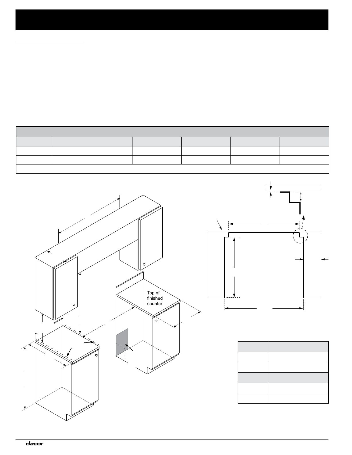
DIMENSIONS
Model F G H I J
HGPR36S 42” (106.2 cm)*; 36” (91.4 cm)** 36” (91.4 cm)** 33 1/2” (84.8 cm) 30 7/8” (78.4 cm) 3 1/2” (8.9 cm)
HGPR48S 54” (137.2 cm)*; 48” (121.9 cm)** 48” (121.9 cm)** 43 1/2” (110.2 cm) 29 7/8” (75.9 cm) 3” (7.6 cm)
* Recommended ** Minimum
Note 2
F
G
2
Cabinet/countertop depth is at discretion of customer but
cabinet face MUST NOT protrude further than rear of front
panel, see product dimensions.
3
Consult local code for exact location requirements.
1
Vertical from range grate level to combustible overhead
surface; if installing an overhead vent hood, also check
hood specifications for minimum required clearances.
4
Vertical from grate level to combustible surface.
Non-combustible
surface along back wall
recommended
10” (25.4 cm) min.
to combustible side
walls above the range
(both sides)
30” (76.2 cm)
min.
1
37 1/2”
(95.3 cm)
max.
13” (33.0 cm)
max.
5
15” (38.1 cm)
min.
4, 5
5
This specification does not apply for cabinets more
than a horizontal distance of 10” (25.4 cm) from the
edge of the range.
Suggested
location of
utilities
3
Grate
level
G
10" (25.4 cm) min.
to combustible side
walls above the range
(on both sides)
non-combustible
rear wall (recommended)
H
Backsplash
3/8" (1.0 cm)
min. for downdraft cap
clearance
J
Note 2
Cutout tolerances: +1/16” (+1.6 mm),
-0 unless otherwise stated
Range Downdraft Vent
HGPR36S ERV36-ER
HGPR48S ERV48-ER
Range 1.5” Low-Profile Backguard
HGPR36S APB36GLP
HGPR48S APB48GLP
Cabinet Layout
• All maximum/minimum dimensions and clearances in the
diagrams below must be maintained for safe operation.
• Install the range away from drafts, and include a hood or
approved downdraft.
• For safety’s sake, do not install cabinets above the range; other-
wise, install a hood that extends 5” or more past the cabinet face.
• The range may be installed against the rear wall. You should
install a backguard or non-combustible material on the wall
between the range and hood. Non-combustible material is not
needed behind the range from countertop to floor.
• Seal openings in the wall behind the range or in the floor below.
Gas and Electrical Service
• The shaded area in the diagram below shows the recommended
location of the gas inlet and the electrical outlet. (If replacing a
range, the existing utilities may be used if they do not interfere
with the placement of this range. Check local codes for
permissible gas-valve locations.)
• An external, manual shut-off valve must be installed between
the gas inlet and range so the gas supply can be turned on/off
• The installation must also allow:
- access to the gas shut-off valve when the unit is installed.
- access to the electrical outlet, when the range is in place.
- the range to be pulled out for service without disconnecting
the gas and electrical supply.
Loading ...
Loading ...
Loading ...