CP SERIES
OWNER’S MANUAL

RECOMMENDED RECEIVER/AMPLIFIER POWER TO USE WITH KLIPSCH CP SPEAKERS
A speaker can be damaged just as easily with too little power as
with too much power. A general rule is when you raise the volume
level on a receiver/amplifier past the “one half” (or “12 o’clock”
position with a marked volume knob), that receiver/amplifier is now
starting to work beyond its capabilities, sending harmful distortion
that can damage any speaker, no matter how many watts that
speaker is rated to accept. This is true for any speaker and receiver/
amplifier combination. The recommended wattage to use on your
new Klipsch CP speaker depends on which one you have you have:
CP-4: up to 50 watts continuous (for an extended period of time);
200 watt “peaks” (very short bursts/surges)
CP-6: up to 75 watts continuous (for an extended period of time);
300 watt “peaks” (very short bursts/surges)
HOOKING SPEAKERS UP TO AN AMPLIFIER/RECEIVER
When connecting speakers to an amplifier/receiver, always
make sure speaker polarity is correct and the best sound is
obtained by connecting amp/receiver positive (+) to speaker
positive (+) and amp/receiver negative (-) to speaker negative
(-). The CP speaker terminals are designed to accept up to 16
gauge wire.
One pair of Klipsch CP Series speakers, 8 Ohms, can connect to
the left/right speaker terminals of any 8 Ohm rated amplifier/
receiver as shown:
+
-
+
-
+
-
+
-
+
-
+
-
ONE PAIR TO
8Ω CAPABLE
AMP/RECEIVER
Right Channel Left Channel
+
-
+
-
+
-
+
-
PARALLEL WIRING TWO PAIRS TO
4Ω CAPABLE AMP/RECEIVER
Right Channels Left Channels
+
-
+
-
+
-
+
-
+
-
+
-
SERIES WIRING TWO PAIRS TO
16Ω CAPABLE AMP/RECEIVER
Right Channels Left Channels
R
+
L
+
_
_
R
+
L
+
_
_
SPK A SPK B
Amp/Receiver Rear Amp/Receiver Front
SPK A SPK B

IF YOU WISH TO USE TWO PAIRS OF KLIPSCH CP
SERIES SPEAKERS ON ONE AMPLIFIER/RECEIVER
WE RECOMMEND ONE OF TWO METHODS:
Method 1 (Preferred): IF your amp/receiver has both A
and B speaker terminals, connect one pair to A and one
to B. Depending on your amp/receiver’s capability you
can then either play Speaker pairs A and B together or
separately or Speaker pair A OR Speaker pair B only.
Method 2: IF YOUR AMP/RECEIVER IS RATED TO 4
OHMS OR LESS make a parallel wire connection as shown
from the amp/receiver’s right and left speaker terminals.
Your amp/receiver may output more power to the
speakers this way (check amp/receiver specifications).
OTHER POSSIBLE SPEAKER CONNECTION OPTIONS:
Series Wiring of Two Pairs to one Amp/Receiver:
Instead
of a parallel connection using a series connection as
shown has the amp/receiver work at 16 Ohms but this cuts
the power going to each of the speakers usually in half.
If you are using a surround (7/9/11 channel) receiver
that receiver MIGHT allow connection of an additional
pair of speakers to unused surround channels for use in a
different listening area or may have a “Zone 2” capability
to connect those speakers (check your receiver manual)
Using an outboard speaker switcher:
Several types of
available selector boxes allow hookup of multiple pairs
of speakers to one amplifier/receiver and allow switching
between them. Some models allow simultaneous play of two
pairs of speakers. (see your audio dealer for availability).
+
-
+
-
+
-
+
-
+
-
+
-
ONE PAIR TO
8Ω CAPABLE
AMP/RECEIVER
Right Channel Left Channel
+
-
+
-
+
-
+
-
PARALLEL WIRING TWO PAIRS TO
4Ω CAPABLE AMP/RECEIVER
Right Channels Left Channels
+
-
+
-
+
-
+
-
+
-
+
-
SERIES WIRING TWO PAIRS TO
16Ω CAPABLE AMP/RECEIVER
Right Channels Left Channels
R
+
L
+
_
_
R
+
L
+
_
_
SPK A SPK B
Amp/Receiver Rear Amp/Receiver Front
SPK A SPK B
HOOKING SPEAKERS UP TO AN AMPLIFIER/RECEIVER (CONTINUED)
+
-
+
-
+
-
+
-
+
-
+
-
ONE PAIR TO
8Ω CAPABLE
AMP/RECEIVER
Right Channel Left Channel
+
-
+
-
+
-
+
-
PARALLEL WIRING TWO PAIRS TO
4Ω CAPABLE AMP/RECEIVER
Right Channels Left Channels
+
-
+
-
+
-
+
-
+
-
+
-
SERIES WIRING TWO PAIRS TO
16Ω CAPABLE AMP/RECEIVER
Right Channels Left Channels
R
+
L
+
_
_
R
+
L
+
_
_
SPK A SPK B
Amp/Receiver Rear
Amp/Receiver Front
SPK A SPK B
+
-
+
-
+
-
+
-
+
-
+
-
ONE PAIR TO
8Ω CAPABLE
AMP/RECEIVER
Right Channel Left Channel
+
-
+
-
+
-
+
-
PARALLEL WIRING TWO PAIRS TO
4Ω CAPABLE AMP/RECEIVER
Right Channels Left Channels
+
-
+
-
+
-
+
-
+
-
+
-
SERIES WIRING TWO PAIRS TO
16Ω CAPABLE AMP/RECEIVER
Right Channels Left Channels
R
+
L
+
_
_
R
+
L
+
_
_
SPK A SPK B
Amp/Receiver Rear Amp/Receiver Front
SPK A SPK B
METHOD 2
METHOD 1
SERIES WIRING OF TWO PAIRS
TO ONE AMP/RECEIVER

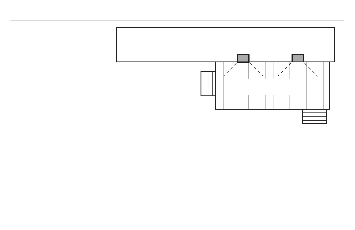
SUGGESTED SPEAKER PLACEMENT
X
X
X
House
Mount Speakers horizontal
under roof eaves and point
down towards deck
Speakers disperse sound 90°
to cover whole deck evenly
STEREO ROOM PLACEMENT EXAMPLE AS SURROUND SPEAKERS ROOM PLACEMENT EXAMPLE
Speakers same distance apart(X) as their
distance to main listening positition
5.1 surrond: 2 side speakers
7.1 surround: 2 side/2 rear speakers
(all speaker 5-6’ (1.5 - 2m) above floor)

X
X
X
House
Mount Speakers horizontal
under roof eaves and point
down towards deck
Speakers disperse sound 90°
to cover whole deck evenly
SUGGESTED SPEAKER PLACEMENT (CONTINUED)
If speakers are covering a very
large listening area (i.e. large
patio/deck) you may be able
to send a mono signal (L+R
channel) to both speakers so
that all listeners hear everything
even if far from one speaker. See
amplifier/receiver manual to see if
it allows this.
(It is recommended when mounting CP
speakers outdoors to shield them from
direct rain, etc. by mounting under eaves
or another type of cover.)
Other Mounting/Placement Tips:
• Mounting a speaker in a corner or wall/ceiling
c o r n e r w i l l i n c r e a s e i t s b a s s r e s p o n s e a n d l o u d n e s s
make sure a speaker is not mounted/placed where an
obstruction is in front of it that blocks sound
• Aiming a speaker at the main listening area reduces
reflections from walls/ceilings and improves sound quality
• When covering a large area such as a deck or patio, you
can send a mono signal (left + right channel) if your amp/
receiver allows through each speaker instead of stereo so
if listeners are spread out they hear all of the music.

WHAT’S INSIDE
Speakers (x2)
Brackets (x2)
Grills (x2) Mounting Template Grill Remover Tool
Mount Wall Bracket Template for CP-4/4T
MAKE SURE TEMPLATE IS LEVEL BEFORE DRILLING PILOT HOLES!
Horizontal
Pilot Hole
Vertical
Pilot Hole
Vertical
Pilot Hole
Horizontal
Pilot Hole
MAKE SURE TEMPLATE IS LEVEL
BEFORE DRILLING PILOT HOLES!
To mount speaker HORIZONTALLY UP in ceiling/wall corner putting bracket on wall
put THIS SIDE on wall flush against ceiling and mark horizontal pilot holes
To mount speaker vertically in corner PUTTING
BRACKET ON LEFT WALL against corner put THIS SIDE
flush in corner on left wall and mark vertical pilot holes
To mount speaker vertically in corner PUTTING
BRACKET ON RIGHT WALL against corner put
THIS SIDE flush in corner on left wall and mark
vertical pilot holes
CP SERIES
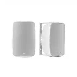
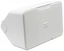
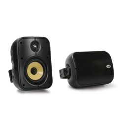
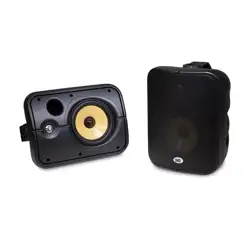
Thank you for your purchase of the Klipsch CP Series speakers!
They are designed to both withstand the rigors of outdoor use
while also complimenting any indoor décor as either a stereo pair
or surround speakers in a home Theater system. The included,
unique wall bracket provides for easy horizontal or vertical wall-
mounting and even allows for a tight mounting tucked into a corner
for a highly aesthetic look that also adds bass output. Shelf or
table placement is an added option. The exclusive Klipsch 90°x
90° Tractrix
®
Horn not only provides controlled coverage, reducing
reflected sound which harms overall sound quality, but also gives
you more sound output from the same amount of power input
compared to other designs. The long-throw woofers are combined
with front-firing ports for tight, musical bass no matter how they
are mounted or placed.
Bracket Retaining
Screws (x4)

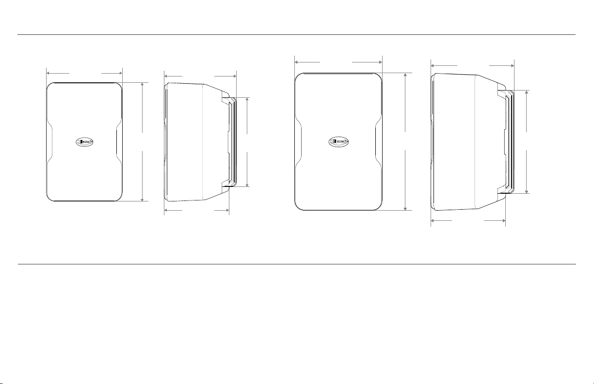
SPEAKER DIMENSIONS WITH/WITHOUT INCLUDED BRACKETS
CP-4
CP-6
If wall mounting speakers, run speaker wire behind wall to mounting spots (if desired)
If wall-mounting with brackets you will also need:
a) A level
b) A pencil
c) A Philips screwdriver (#2 size)
d) Two #10 or #12 2.5-3 inch (4-5cm) Pan Head Screws for mounting into wall stud OR
minimum 10 lb. (5 kg) Wall Anchors for mounting if stud unavailable
BEFORE SPEAKER INSTALLATION/CONNECTION
5.5”
(14.0cm)
8.8”
(22.4cm)
7.2”
(18.3cm)
5.5”
(14.0cm)
4.7”
(11.9cm)
7.0 ”
(17.8cm)
11.0”
(27.9cm)
9.4”
(23.9cm)
6.9”
(17.5cm)
6.1”
(15.5cm)

STEP 1
OR
Choose speaker location and run speaker wire to location. Use included template
and a level to mark bracket hole locations where speaker will be mounted.
Typical Wall-Mounting With Included Bracket (Level not included)
If Wall/Wall Corner or Ceiling/Wall Corner Mounting With Included Bracket
V
V
H H
V
V
H H
V
V
H H
V
V
H H
V
V
H H
V
V
H H
V
V
H H
V
V
H H
OR

STEP 2
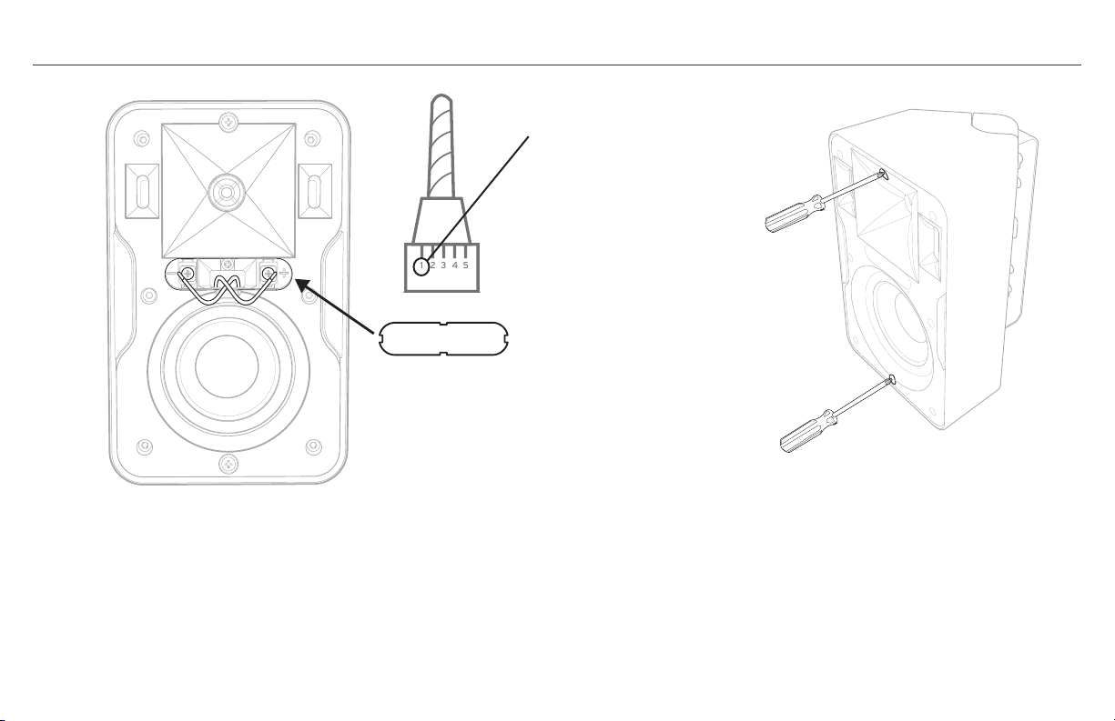
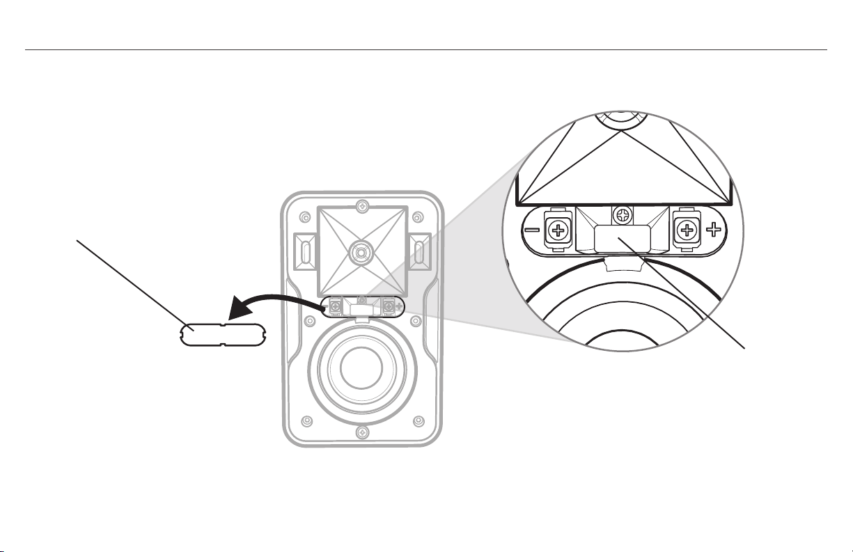
Remove rubber terminal cover on speaker front and push speaker wire through
middle channel on speaker back until pushed through speaker front where cover was.
Terminal Cover
Speaker Wire Channel
Speaker
Wires
OR

STEP 2 (CONTINUED)
IF USING SUPPLIED BRACKET
A. Run speaker wire through hole in bracket back and attach wall
bracket to wall
B. Slide speaker partially onto bracket arms and channel wire
from back to front
C. To keep speaker on bracket while adjusting use Phillips head
screwdriver and partially screw in front top/bottom bracket
screws (2-3 revolutions) then gently pull out speaker to detente
position 3/4ths of way on bracket.
D. WITH SPEAKER STILL PULLED OUT TO FIRST “STOP”
POSITION ON BRACKET adjust speaker to desired angle on wall.
Speaker
Wires
OR
A.
B.
C. D.
Speaker
Wires
OR
Speaker
Wires
OR
Speaker
Wires
OR
Use #10-#12, 2.5-3 INCH
Pan Head Screws
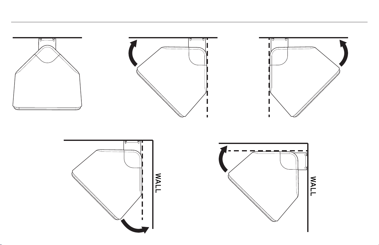
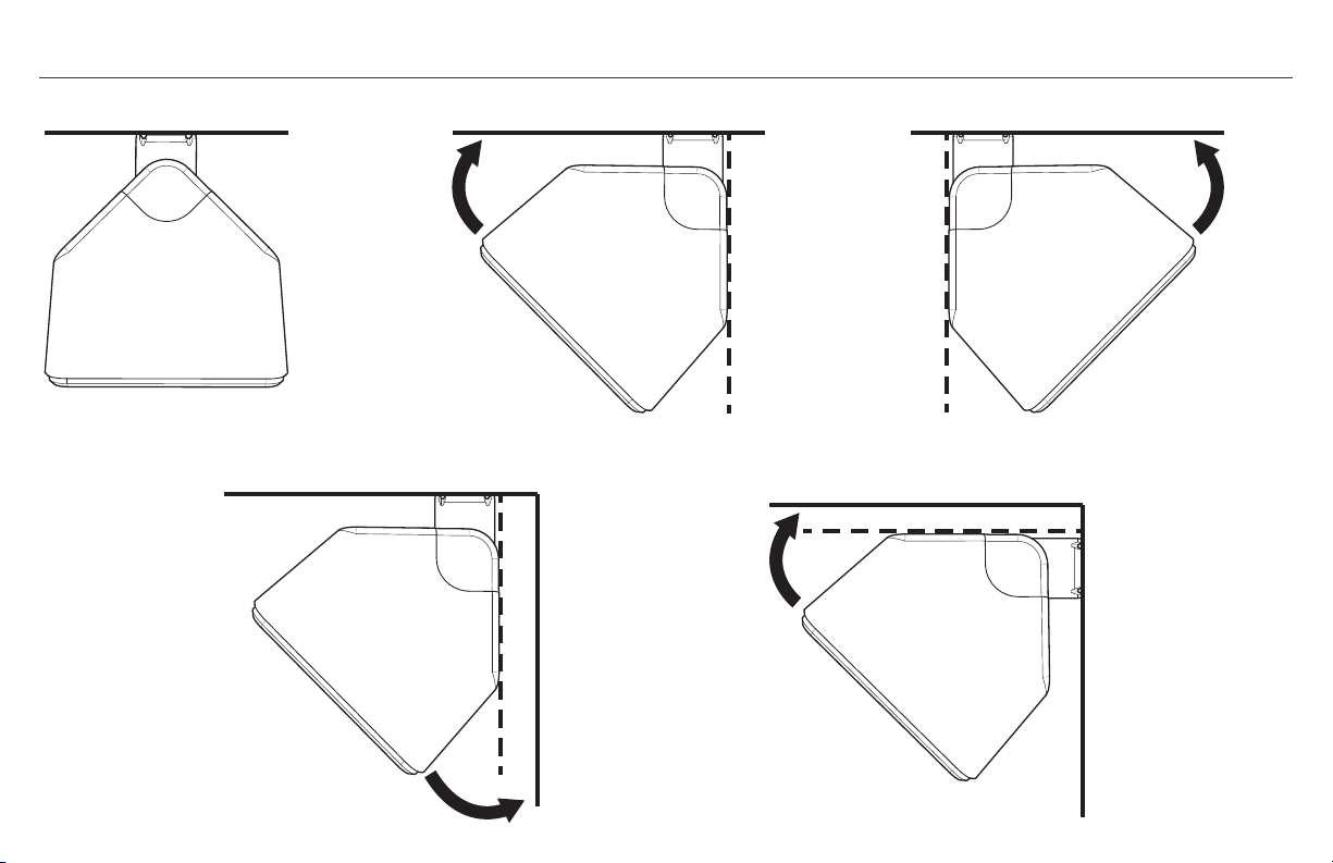
MOUNTING OPTIONS
45˚
45˚
45˚
WALL
45˚
CEILING OR WALL
45˚
45˚
45˚
WALL
45˚
CEILING OR WALL
45˚
45˚
45˚
WALL
45˚
CEILING OR WALL
45˚
45˚
45˚
WALL
45˚
CEILING OR WALL
45˚
45˚
45˚
WALL
45˚
CEILING OR WALL
OR OR

STEP 3
A. Connect Speaker Wires to Speaker Terminals with screwdriver
or DRILL SET ON LOWEST TORQUE SETTING WITH #2 PHILIPS
SCREWDRIVER BIT. Observe the correct polarity. Usually, red
wire is positive (+) and black is negative (–). It does not matter
which wire is connected to the positive or negative terminal as
long as the connections are consistent on all speakers in the
same system. Make sure both wires are pushed inside slot and
replace terminal cover.
IF USING SUPPLIED BRACKET
B. Once speaker is positioned as desired push back all the way back
on bracket arms until flush with bracket caps and screw two
inserted screws all the way in to lock position.
Lowest Dril Torque Setting
A.
B.
1 2 3 4 5

STEP 4
USING DIFFERENT MOUNTING BRACKETS
TEST SOUND: Play music through speaker to make sure
connections are tight and polarity is correct
STEP 5
Once speaker is in the final position and tested, attach grill by
pressing grill into channel encircling speaker front
*SPEAKER GRILL REMOVAL: Use included grill removal tool, insert into a top corner and
gently pull out. Repeat on a corner next to first one pulled, then pull out grill gently with
hand. NOTE: the grill is designed to fit snug on speaker to both remain on and to remain
tight. Continued removal/reinsertion of grill may make it loose and subject to either
vibration or slippage.
All CP Series speakers have a 1/4”, 20-thread insert on the back
bottom that you can attach a different, compatible mount.
3
2
4
5
1

PAINTING THE SPEAKERS
Paint speaker and bracket top/
bottom caps separately.
1. First, clean speaker cabinet
and bracket top/bottom caps
with mild solvent or mild
detergent/water
2. Then create a paint mask for
speaker front (baffle) by tracing
speaker grill on sheet of thicker,
non-porous paper then cutting
paper around tracing.
3. Place grill paper mask on front
of speaker (over baffle) making
sure to also cover grill channel;
secure with double sided tape.
Do not put tape on woofer. Mask
around bracket top/bottom caps
making sure not to paint bracket
arm and swivel mechanism.
Mask logo on grill front.
4. Use a spray paint that is made
for plastic and spray speaker
cabinet, bracket caps and grill
front. Make sure not to cover
grill holes. Allow all parts to dry
before re-assembling speaker.
1. 2.
3.
4.

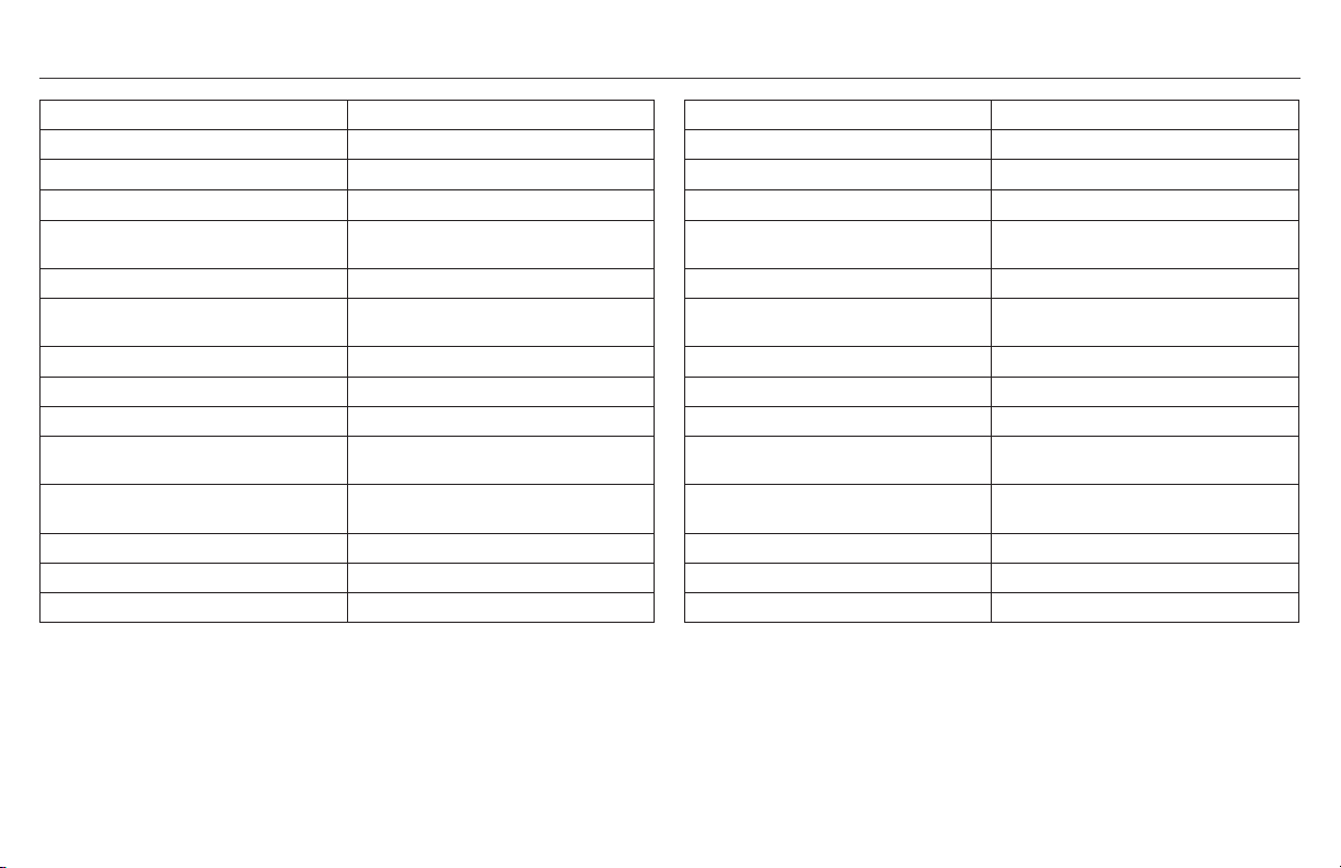
CP-4 SPECIFICATIONS CP-6 SPECIFICATIONS
FREQUENCY RESPONSE
1
80Hz-22kHz +3/-6 dB
POWER HANDLING
2
50 w (200 peak)
SENSITIVITY
3
91 dB @ 1 watt/1 meter
NOMIMAL IMPEDANCE 8 ohms
TWEETER .75" (1.9cm) aluminum dome tweeter
HIGH FREQUENCY HORN 90° x 90° Tractrix
®
Horn
WOOFER 3.5" (8.9cm) long-throw IMG woofer
CROSSOVER FREQUENCY 3.2kHz 12dB octave
ENCLOSURE TYPE Bass-reflex via dual front-firing ports
WEIGHT 4.8 lbs. (2.2kg)
DIMENSIONS 8.8"(22.4cm) H x 5.5"(14.0cm) W x
4.7"(11.9cm) D
DIMENSIONS WITH WALL MOUNT 8.8"(22.4cm) H x 5.5"(14.0cm) W x
5.5"(14.0cm) D
FINISHES White/Black enclosure and grill
WIRE GAUGE ACCOMMODATED 16
BUILT FROM 2014
1
3M anechoic
2
IEC 268-5 filtered pink noise with 6dB crest factor
3
SPL at 1M, anechoic with 2.83V input
FREQUENCY RESPONSE
1
70Hz-22kHz +3/-6 dB
POWER HANDLING
2
75 w (300 peak)
SENSITIVITY
3
94 dB @ 1 watt/1 meter
NOMIMAL IMPEDANCE 8 ohms
TWEETER .75" (1.9cm) aluminum dome tweeter
HIGH FREQUENCY HORN 90° x 90° Tractrix® Horn
WOOFER 5.25" (13.3cm) long-throw IMG woofer
CROSSOVER FREQUENCY 3kHz 12dB octave
ENCLOSURE TYPE Bass-reflex via dual front-firing ports
WEIGHT 5.8 lbs. (2.6kg)
DIMENSIONS 11.0"(27.9cm) H x 7.0"(17.8cm) W x
6.1"(15.5cm) D
DIMENSIONS WITH WALL MOUNT 11.0"(27.9cm) H x 7.0"(17.8cm) W x
6.9"(17.5cm) D
FINISHES White/Black enclosure and grill
WIRE GAUGE ACCOMMODATED 16
BUILT FROM 2014
1
3M anechoic
2
IEC 268-5 filtered pink noise with 6dB crest factor
3
SPL at 1M, anechoic with 2.83V input

PUISSANCE RECOMMANDÉE POUR LE RÉCEPTEUR/AMPLIFICATEUR À UTILISER AVEC LES ENCEINTES KLIPSCH DE LA SÉRIE CP
Une enceinte peut être endommagée aussi facilement avec
une puissance insuffisante qu’avec une puissance excessive. En
règle générale, lorsque vous montez le volume d’un récepteur/
amplificateur au-dessus de la « moitié » (soit la position « midi
» avec un bouton de volume rotatif), le récepteur/amplificateur
commence à travailler au-delà de ses capacités, envoyant une
distorsion néfaste qui peut endommager n’importe quel haut-
parleur, quelle que soit la puissance nominale que ce haut-
parleur peut accepter. Ceci est vrai pour toute combinaison
alliant une enceinte à un récepteur/amplificateur. La puissance
recommandée pour votre nouvelle enceinte Klipsch de la série
CP dépend du modèle que vous avez :
CP-4 : jusqu’à 50 watts en continu (pendant une longue durée) ;
« crêtes » de 200 watts (très courts pics/créneaux)
CP-6 : jusqu’à 75 watts en continu (pendant une longue durée) ;
« crêtes » de 300 watts (très courts pics/créneaux)
BRANCHEMENT DES ENCEINTES À UN AMPLIFICATEUR/RÉCEPTEUR
Lorsque vous raccordez des enceintes à un amplificateur/
récepteur, veillez toujours à ce que la polarité de l’enceinte
soit correcte et à ce que le meilleur son soit obtenu en
reliant la borne positive (+) de l’amplificateur/récepteur à la
borne positive (+) de l’enceinte et la borne négative (-) de
l’amplificateur/récepteur à la borne négative (-) de l’enceinte.
Les bornes des enceintes CP sont conçues pour brancher un fil
d’un diamètre maximum de 1,3 mm (16 AWG).
Une paire d’enceintes Klipsch de la série CP, 8
Ω
, peut être
branchée comme illustré aux bornes d’enceintes gauche/droite de
n’importe quel amplificateur/récepteur d’une impédance nominale
de 8
Ω
.
+
-
+
-
+
-
+
-
+
-
+
-
ONE PAIR TO
8Ω CAPABLE
AMP/RECEIVER
Right Channel Left Channel
+
-
+
-
+
-
+
-
PARALLEL WIRING TWO PAIRS TO
4Ω CAPABLE AMP/RECEIVER
Right Channels Left Channels
+
-
+
-
+
-
+
-
+
-
+
-
SERIES WIRING TWO PAIRS TO
16Ω CAPABLE AMP/RECEIVER
Right Channels Left Channels
R
+
L
+
_
_
R
+
L
+
_
_
SPK A SPK B
Amp/Receiver Rear Amp/Receiver Front
SPK A SPK B
Branchement d’une paire à un
amplificateur/récepteur conçu
pour supporter 8 Ω
Voie droite Voie gauche

SI VOUS SOUHAITEZ UTILISER DEUX PAIRES D’ENCEINTES
KLIPSCH DE LA SÉRIE CP SUR UN AMPLIFICATEUR/
RÉCEPTEUR, NOUS RECOMMANDONS L’UNE DES DEUX
MÉTHODES SUIVANTES :
Méthode 1 (préférée) : Si votre amplificateur/récepteur est doté de
bornes d’enceintes A et B, branchez une paire sur A et une paire
sur B. Selon les possibilités de votre amplificateur/récepteur, vous
pourrez alors utiliser les paires d’enceintes A et B simultanément
ou séparément, ou utiliser uniquement la paire d’enceintes A OU
la paire d’enceintes B.
Méthode 2 : SI VOTRE AMPLIFICATEUR/RÉCEPTEUR A
UNE IMPÉDANCE NOMINALE DE 4
Ω
OU MOINS, utilisez un
branchement en parallèle, comme illustré, à partir des bornes
d’enceintes droite et gauche de l’amplificateur/récepteur.
Votre amplificateur/récepteur pourra transmettre davantage
de puissance aux enceintes de cette manière (vérifiez les
caractéristiques de l’amplificateur/récepteur).
Branchement en série de deux paires à un amplificateur/récepteur:
Au lieu d’un branchement en parallèle, un branchement en série
(comme illustré) permet à l’amplificateur/récepteur de travailler
sous 16
Ω
, mais cela réduit généralement de moitié la puissance
fournie à chacune des enceintes.
Si vous utilisez un récepteur surround (à 7/9/11 voies), il est
POSSIBLE que ce récepteur permette le branchement d’une
paire d’enceintes supplémentaire sur des voies surround
inutilisées afin de couvrir une zone d’écoute différente, ou qu’il
offre une « Zone 2 » pour brancher ces enceintes (consultez le
manuel de votre récepteur).
Si vous utilisez un récepteur surround (à 7/9/11 voies), il est POSSIBLE
que ce récepteur permette le branchement d’une paire d’enceintes
supplémentaire sur des voies surround inutilisées afin de couvrir une
zone d’écoute différente, ou qu’il offre une « Zone 2 » pour brancher
ces enceintes (consultez le manuel de votre récepteur).
+
-
+
-
+
-
+
-
+
-
+
-
ONE PAIR TO
8Ω CAPABLE
AMP/RECEIVER
Right Channel Left Channel
+
-
+
-
+
-
+
-
PARALLEL WIRING TWO PAIRS TO
4Ω CAPABLE AMP/RECEIVER
Right Channels Left Channels
+
-
+
-
+
-
+
-
+
-
+
-
SERIES WIRING TWO PAIRS TO
16Ω CAPABLE AMP/RECEIVER
Right Channels Left Channels
R
+
L
+
_
_
R
+
L
+
_
_
SPK A SPK B
Amp/Receiver Rear Amp/Receiver Front
SPK A SPK B
BRANCHEMENT DES ENCEINTES À UN AMPLIFICATEUR/RÉCEPTEUR
+
-
+
-
+
-
+
-
+
-
+
-
ONE PAIR TO
8Ω CAPABLE
AMP/RECEIVER
Right Channel Left Channel
+
-
+
-
+
-
+
-
PARALLEL WIRING TWO PAIRS TO
4Ω CAPABLE AMP/RECEIVER
Right Channels Left Channels
+
-
+
-
+
-
+
-
+
-
+
-
SERIES WIRING TWO PAIRS TO
16Ω CAPABLE AMP/RECEIVER
Right Channels Left Channels
R
+
L
+
_
_
R
+
L
+
_
_
SPK A SPK B
Amp/Receiver Rear
Amp/Receiver Front
SPK A SPK B
+
-
+
-
+
-
+
-
+
-
+
-
ONE PAIR TO
8Ω CAPABLE
AMP/RECEIVER
Right Channel Left Channel
+
-
+
-
+
-
+
-
PARALLEL WIRING TWO PAIRS TO
4Ω CAPABLE AMP/RECEIVER
Right Channels Left Channels
+
-
+
-
+
-
+
-
+
-
+
-
SERIES WIRING TWO PAIRS TO
16Ω CAPABLE AMP/RECEIVER
Right Channels Left Channels
R
+
L
+
_
_
R
+
L
+
_
_
SPK A SPK B
Amp/Receiver Rear Amp/Receiver Front
SPK A SPK B
MÉTHODE 2
MÉTHODE 1
Branchement en série de deux paires
à un amplificateur/récepteur conçu
pour supporter 16
Ω
Arrière de
l’amplificateur/récepteur
Devant de
l’amplificateur/récepteur
Enceintes A Enceintes B
Enceintes A Enceintes B
Voie gaucheVoie droite
Voie gaucheVoie droite

POSITION SUGGÉRÉE DES ENCEINTES
X
X
X
House
Mount Speakers horizontal
under roof eaves and point
down towards deck
Speakers disperse sound 90°
to cover whole deck evenly
EXEMPLE D’AGENCEMENT D’UNE PIÈCE POUR
ENCEINTES STÉRÉO
ENCEINTE MONTÉE AU MUR
EXEMPLE D’AGENCEMENT D’UNE PIÈCE POUR
ENCEINTES SURROUND
Distance entre les enceintes (X) égale à leur
distance à la position d’écoute principale.
Surround 5.1 : 2 enceintes latérales
Surround 7.1 : 2 enceintes latérales/2 enceintes arrière
(toutes les enceintes entre 1,5 et 2 m au-dessus du sol)

X
X
X
House
Mount Speakers horizontal
under roof eaves and point
down towards deck
Speakers disperse sound 90°
to cover whole deck evenly
POSITION SUGGÉRÉE DES ENCEINTES
Si les enceintes couvrent une zone
d’écoute très importante (c’est-à-dire,
un patio ou une terrasse de grande
superficie), il pourra être préférable
d’envoyer un signal mono (voie D+G) aux
deux enceintes pour que tout le monde
entende la totalité du signal sonore,
même les personnes se trouvant loin
d’une des enceintes. Consultez le manuel
de l’amplificateur/récepteur pour voir si
cette option est disponible.
(Lors du montage des enceintes CP à
l’extérieur, il est recommandé de les protéger
de la pluie, etc., en les installant sous
une avancée de toit ou un autre type de
protection.)
Autres conseils concernant le montage/la position :
• L’installation d’une enceinte dans un angle ou à
l’intersection d’un mur et d’un plafond augmente sa
réponse dans les graves et son intensité sonore
• Veillez à ce qu’une enceinte ne soit pas montée/placée
derrière une obstruction qui bloque le son
• Orienter une enceinte vers la zone d’écoute principale
réduit les réflexions sur les murs/plafonds et améliore la
qualité sonore
• Pour couvrir une zone étendue, telle qu’une terrasse ou
un patio, vous pouvez, si votre amplificateur/récepteur le
permet, envoyer à chaque enceinte un signal mono (voie
gauche + droite) au lieu d’un signal stéréo, de manière à
ce que les personnes se trouvant en différents endroits
entendent toute la musique.
Montez les enceintes en
position horizontale sous
l’avancée de toit et orientez-les
vers la terrasse
Les enceintes dispersent le son sur
90º pour couvrir uniformément la
totalité de la terrasse
Maison

CONTENU DE LA BOÎTE
Eceintes (x2) Supports (x2) Grilles (x2) Vis (x4) Gabarit Outil de Grille
Mount Wall Bracket Template for CP-4/4T
MAKE SURE TEMPLATE IS LEVEL BEFORE DRILLING PILOT HOLES!
Horizontal
Pilot Hole
Vertical
Pilot Hole
Vertical
Pilot Hole
Horizontal
Pilot Hole
MAKE SURE TEMPLATE IS LEVEL
BEFORE DRILLING PILOT HOLES!
To mount speaker HORIZONTALLY UP in ceiling/wall corner putting bracket on wall
put THIS SIDE on wall flush against ceiling and mark horizontal pilot holes
To mount speaker vertically in corner PUTTING
BRACKET ON LEFT WALL against corner put THIS SIDE
flush in corner on left wall and mark vertical pilot holes
To mount speaker vertically in corner PUTTING
BRACKET ON RIGHT WALL against corner put
THIS SIDE flush in corner on left wall and mark
vertical pilot holes
LA SÉRIE CP
Merci d’avoir acheté les enceintes Klipsch de la série CP ! Elles
sont conçues autant pour endurer les rigueurs d’une utilisation en
extérieur que pour agrémenter un décor intérieur en tant que paire
stéréo ou enceintes surround d’un système de cinéma maison. Le
support mural spécial qui est fourni assure un montage mural aisé,
que ce soit en position horizontale ou verticale, et permet même
un montage serré en angle pour une apparence extrêmement
esthétique qui augmente en outre le volume des graves. Une autre
option consiste à poser les enceintes sur une étagère ou une table.
Exclusivité de Klipsch, le pavillon Tractrix® 90°x 90° offre non
seulement une couverture contrôlée, réduisant le son réfléchi qui
nuit à la qualité sonore globale, mais fournit également, par rapport
aux autres modèles, une puissance de sortie plus élevée pour la
même puissance d’entrée. Les woofers longue portée sont associés
à des ports frontaux pour produire des graves précis et mélodieux
quelle que soit la position où ils sont montés ou placés.

DIMENSIONS DES ENCEINTES AVEC/SANS LES SUPPORTS FOURNIS
CP-4
CP-6
Si vous montez les enceintes sur un mur, acheminez le fil d’enceinte derrière le mur jusqu’à l’endroit
de l’installation (si désiré)
Pou r une installation murale avec les supports, i l vo us faudra également :
a) Un niveau
b) Un crayon
c) Un tournevis cruciforme (taille 2)
d) Deux vis à tête cylindrique bombée de 5 ou 5,5 mm de diamètre et 60 à 75 mm de longueur
pour un montage dans un poteau mural OU des chevilles pour mur creux capables de
supporter 5 kg minimum si un poteau n’est pas disponible.
AVANT L’INSTALLATION/LE BRANCHEMENT DES ENCEINTES
5.5”
(14.0cm)
8.8”
(22.4cm)
7.2”
(18.3cm)
5.5”
(14.0cm)
4.7”
(11.9cm)
7.0 ”
(17.8cm)
11.0”
(27.9cm)
9.4”
(23.9cm)
6.9”
(17.5cm)
6.1”
(15.5cm)

ÉTAPE 1
OU
Choisissez l’emplacement de l’enceinte et acheminez du fil d’enceinte jusqu’à cet endroit. Utilisez le gabarit
fourni et un niveau pour marquer l’emplacement des trous du support à l’endroit où l’enceinte sera installée.
Montage mural typique avec le support fourni
Montage en angle ou à l’intersection d’un mur et d’un plafond avec le support fourni
V
V
H H
V
V
H H
V
V
H H
V
V
H H
V
V
H H
V
V
H H
V
V
H H
V
V
H H
OU

ÉTAPE 2
Retirez le cache en caoutchouc qui couvre les bornes sur le devant de l’enceinte et
insérez le fil d’enceinte dans le passage du milieu à l’arrière de l’enceinte jusqu’à ce
qu’il ressorte sur le devant de l’enceinte à l’endroit où se trouvait le cache.
Cache des bornes
Passage pour le fil d’enceinte
Speaker
Wires
OR

ÉTAPE 2
POUR UTILISER LE SUPPORT FOURNI
A. Passez le fil d’enceinte dans le trou situé à l’arrière du support
et fixez le support mural au mur
B. Glissez partiellement l’enceinte sur les bras du support et
acheminez le fil de l’arrière à l’avant
C.
Pour maintenir l’enceinte sur le support pendant l’ajustement,
utilisez un tournevis cruciforme et vissez partiellement les vis de
fixation en haut et en bas du support (2 à 3 tours), puis reculez
doucement l’enceinte jusqu’à la position de réglage, à 3/4 de la
course sur le support.
D. EN MAINTENANT L’ENCEINTE À LA PREMIÈRE POSITION
« D’ARRÊT » SUR LE SUPPORT, ajustez l’enceinte à l’angle
souhaité sur le mur.v
Speaker
Wires
OR
A.
B.
C. D.
Speaker
Wires
OR
Speaker
Wires
OR
Speaker
Wires
OR
ou
FILS D’ENCEINTE
Utilisez des vis à tête
cylindrique bombée de 5 ou
5,5 mm de diamètre et 60 à
75 mm de longueur

45˚
45˚
45˚
WALL
45˚
CEILING OR WALL
45˚
45˚
45˚
WALL
45˚
CEILING OR WALL
45˚
45˚
45˚
WALL
45˚
CEILING OR WALL
45˚
45˚
45˚
WALL
45˚
CEILING OR WALL
45˚
45˚
45˚
WALL
45˚
CEILING OR WALL
ou ou
MUR
MUR
PLAFOND OU MUR
MUR
ÉTAPE 3
A. Raccordez les fils d’enceinte aux bornes de l’enceinte avec un
tournevis ou UNE VISSEUSE RÉGLÉE SUR LE COUPLE MINIMUM
AVEC UN EMBOUT DE VISSAGE CRUCIFORME Nº 2. Respect-
ez la polarité. Généralement, le fil rouge est positif (+) et le fil
noir est négatif (–). Peu importe quel fil est branché à la borne
positive ou négative, tant que les branchements sont les mêmes
sur toutes les enceintes d’un même système. Veillez à ce que les
deux fils soient enfoncés dans les fentes et remettez en place le
cache des bornes.
POUR UTILISER LE SUPPORT FOURNI
B. Une fois l’enceinte dans la position désirée, poussez-la à fond sur
les bras du support jusqu’à venir en contact avec les capuchons
du support, puis vissez complètement les deux vis insérées pour
verrouiller la position.
Exemple de réglage d’une
visseuse au couple minimum
A.
B.
1 2 3 4 5

ÉTAPE 4
UTILISATION DE SUPPORTS DE MONTAGE AUTRES QUE CEUX FOURNIS
TESTEZ LE SON : Passez de la musique par l’enceinte pour
vous assurer que les branchements sont solides et que la
polarité est correcte.
ÉTAPE 5
Une fois l’enceinte en position finale et testée, fixez la grille en
l’insérant dans la rainure suivant le périmètre de l’enceinte.
*RETRAIT DE LA GRILLE DE L’ENCEINTE : Utilisez l’outil fourni pour retirer la grille, insérez-
le dans un coin supérieur et tirez doucement vers vous. Répétez sur un coin adjacent au
premier coin détaché, puis sortez doucement la grille à la main. REMARQUE : la grille est
conçue pour s’encastrer sur l’enceinte de manière à rester fixée en place. Si la grille est
fréquemment retirée et remise en place, elle pourra perdre de son maintien et avoir tendance
à vibrer ou à glisser.
À l’arrière de toutes les enceintes de la série CP se trouve une
douille filetée de 1/4”, 20 filets par pouce, qui vous permet
d’installer une autre fixation compatible.
3
2
4
5
1

PEINTURE DES ENCEINTES
Peignez séparément les enceintes et les
capuchons supérieurs/inférieurs
des supports.
1. Nettoyez d’abord les enceintes et les
capuchons supérieurs/inférieurs des
supports avec un solvant doux ou un
détergent doux et de l’eau.
2. Ensuite, créez un cache à peinture
pour le devant de l’enceinte (baffle)
en traçant le contour de la grille de
l’enceinte sur une feuille de papier
épais et non poreux, puis en découpant
le papier en suivant le tracé.
3. Placez le cache en papier sur le devant
de l’enceinte (sur le baffle), en veillant
à couvrir également la rainure de la
grille, et collez-le avec de l’adhésif
double face. Ne collez pas l’adhésif
sur le woofer. Masquez autour des
capuchons supérieurs/inférieurs des
supports, en prenant soin de ne pas
peindre les bras et le mécanisme
pivotant des supports. Masquez le logo
sur le devant de la grille.
4. Utilisez une bombe de peinture
pour plastique et peignez l’enceinte,
les capuchons du support et le
devant de la grille. Veillez à ne pas
couvrir les trous de la grille. Laissez
sécher toutes les pièces avant de
réassembler l’enceinte.
1. 2.
3.
4.
WHITE-SPIRIT DÉTERGENT
DOUX + EAU
CARACTÉRISTIQUES DU MODÈLE KLIPSCH CP-4 CARACTÉRISTIQUES DU MODÈLE KLIPSCH CP-6
RÉPONSE EN FRÉQUENCE
1
80 Hz - 22 kHz +3/-6 dB
PUISSANCE ADMISSIBLE
2
50 W (200 W en crête)
SENSIBILITÉ
3
91 dB à 1 W/1 m
IMPÉDANCE NOMINALE
8
Ω
TWEETER Tweeter à dôme en aluminium de 0,75
po (1,9 cm)
PAVILLON HAUTES FRÉQUENCES Pavillon Tractrix® 90° x 90°
WOOFER Woofer longue portée IMG de 3,5 po
(8,9 cm)
FRÉQUENCE DE COUPURE 3,2 kHz 12 dB octave
TYPE D'ENCEINTE Bass-reflex via doubles ports frontaux
POIDS 2,2 kg
DIMENSIONS 22,4 cm (hauteur) x 14,0 cm (largeur) x
11,9 cm (profondeur)
DIMENSIONS AVEC FIXATION MURALE
22,4 cm (hauteur) x 14,0 cm (largeur) x
14.0 cm (profondeur)
FINITIONS Blanc/noir (enceinte et grille)
DIAMÈTRE DE FIL COMPATIBLE 1,3 mm (16 AWG)
CONSTRUIT DEPUIS 2014
1
anéchoïque à 3 m
2
IEC 268-5 bruit rose filtré avec facteur de crête de 6 dB
3
Niveau de pression acoustique à 1 m, anéchoïque avec entrée de 2,83 V
RÉPONSE EN FRÉQUENCE
1
70Hz - 22 kHz +3/-6 dB
PUISSANCE ADMISSIBLE
2
75 W (300 W en crête)
SENSIBILITÉ
3
94 dB à 1 W/1 m
IMPÉDANCE NOMINALE
8
Ω
TWEETER Tweeter à dôme en aluminium de 0,75
po (1,9 cm)
PAVILLON HAUTES FRÉQUENCES Pavillon Tractrix® 90° x 90°
WOOFER Woofer longue portée IMG de 5,25 po
(13,3 cm)
FRÉQUENCE DE COUPURE 3 kHz 12 dB octave
TYPE D'ENCEINTE Bass-reflex via doubles ports frontaux
POIDS 2,6 kg
DIMENSIONS 27,9 cm (hauteur) x 17,8 cm (largeur) x
15,5 cm (profondeur)
DIMENSIONS AVEC FIXATION MURALE
27,9 cm (hauteur) x 17,8 cm (largeur) x
17,5 cm (profondeur)
FINITIONS Blanc/noir (enceinte et grille)
DIAMÈTRE DE FIL COMPATIBLE 1,3 mm (16 AWG)
CONSTRUIT DEPUIS 2014
1
anéchoïque à 3 m
2
IEC 268-5 bruit rose filtré avec facteur de crête de 6 dB
3
Niveau de pression acoustique à 1 m, anéchoïque avec entrée de 2,83 V

POTENCIA RECOMENDADA DE AMPLIFICADOR/RECEPTOR PARA LOS ALTAVOCES CP DE KLIPSCH
Los altavoces se pueden dañar igualmente con poca o con
mucha alimentación. La regla general es que cuando se sube
el volumen de un amplificador/receptor más allá de la mitad
(la posición de “las 12” en una perilla de volumen marcada) el
amplificador/receptor comienza a funcionar más allá de sus
capacidades y envía distorsión perjudicial que puede dañar
cualquier altavoz, independientemente de la potencia que
acepte nominalmente. Esto es válido para cualquier combinación
de altavoz y amplificador/receptor. La potencia recomendada
para su nuevo altavoz CP de Klipsch depende del altavoz que
tenga que tener:
CP-4: hasta 50 W continuos (durante largos períodos de tiempo);
máximos de 200 W (ráfagas o subidas de potencia muy cortas).
CP-6: hasta 75 W continuos (durante largos períodos de tiempo);
máximos de 300 W (ráfagas o subidas de potencia muy cortas).
CONEXIÓN DE LOS ALTAVOCES A UN AMPLIFICADOR/RECEPTOR
Cuando conecte los altavoces a un amplificador/receptor,
la polaridad debe ser siempre correcta y el mejor sonido se
obtiene conectando la terminal positiva (+) del amplificador/
receptor a la terminal positiva (+) del altavoz y la terminal
negativa (–) del amplificador/receptor a la terminal negativa (–)
del altavoz. Las terminales del altavoz CP han sido diseñadas
para aceptar cable de hasta calibre 16.
Un par de altavoces de la serie CP de Klipsch de 8
Ω
se puede
conectar a las terminales de altavoz izquierda y derecha de
cualquier amplificador/receptor con impedancia nominal de 8
Ω
,
como se indica.
+
-
+
-
+
-
+
-
+
-
+
-
ONE PAIR TO
8Ω CAPABLE
AMP/RECEIVER
Right Channel Left Channel
+
-
+
-
+
-
+
-
PARALLEL WIRING TWO PAIRS TO
4Ω CAPABLE AMP/RECEIVER
Right Channels Left Channels
+
-
+
-
+
-
+
-
+
-
+
-
SERIES WIRING TWO PAIRS TO
16Ω CAPABLE AMP/RECEIVER
Right Channels Left Channels
R
+
L
+
_
_
R
+
L
+
_
_
SPK A SPK B
Amp/Receiver Rear Amp/Receiver Front
SPK A SPK B
Un par conectado a un
amplificador/receptor de 8 Ω
Canal derecho Canal izquierdo

SI DESEA CONECTAR DOS PARES DE ALTAVOCES DE LA
SERIE CP DE KLIPSCH A UN AMPLIFICADOR/RECEPTOR,
RECOMENDAMOS UNO DE ESTOS DOS MÉTODOS:
Método 1 (preferido): SI el amplificador/receptor tiene terminales
de altavoz A y B, conecte un par a las terminales A y el otro par a
las terminales B. Dependiendo de la capacidad del amplificador/
receptor, es posible hacer funcionar los dos pares juntos o
separadamente, o solamente el par de altavoces A o el par de
altavoces B.
Método 2: SI EL AMPLIFICADOR/RECEPTOR ES DE 4
Ω
O MENOS,
haga una conexión de cable en paralelo, como se muestra, desde las
terminales de altavoz derecha e izquierda del amplificador/receptor.
Es posible que el amplificador/receptor envíe más potencia a
los altavoces de esta manera (verifique las especificaciones del
amplificador/receptor).
Cableado en serie de dos pares de altavoces a un amplificador/
receptor: En vez de la conexión en paralelo, la conexión en serie
que se muestra hace funcionar el amplificador/receptor a 16
Ω
,
pero por lo general reduce a la mitad la potencia que va a cada uno
de los altavoces.
Receptor surround (de 7/9/11 canales): Es posible que este
receptor permita conectar un par de altavoces en los canales
de surround vacantes para ponerlos en otra zona de audición
o tenga terminales de “Zona 2” para conectar estos altavoces
(consulte el manual del receptor).
Conmutador de altavoces independiente: Hay varios tipos de selector
que permiten conectar varios pares de altavoces a un amplificador/
receptor y pasar de uno a otro. Algunos modelos permiten el
funcionamiento simultáneo de dos pares de altavoces (consulte al
distribuidor de audio).
+
-
+
-
+
-
+
-
+
-
+
-
ONE PAIR TO
8Ω CAPABLE
AMP/RECEIVER
Right Channel Left Channel
+
-
+
-
+
-
+
-
PARALLEL WIRING TWO PAIRS TO
4Ω CAPABLE AMP/RECEIVER
Right Channels Left Channels
+
-
+
-
+
-
+
-
+
-
+
-
SERIES WIRING TWO PAIRS TO
16Ω CAPABLE AMP/RECEIVER
Right Channels Left Channels
R
+
L
+
_
_
R
+
L
+
_
_
SPK A SPK B
Amp/Receiver Rear Amp/Receiver Front
SPK A SPK B
CONEXIÓN DE LOS ALTAVOCES A UN AMPLIFICADOR/RECEPTOR
+
-
+
-
+
-
+
-
+
-
+
-
ONE PAIR TO
8Ω CAPABLE
AMP/RECEIVER
Right Channel Left Channel
+
-
+
-
+
-
+
-
PARALLEL WIRING TWO PAIRS TO
4Ω CAPABLE AMP/RECEIVER
Right Channels Left Channels
+
-
+
-
+
-
+
-
+
-
+
-
SERIES WIRING TWO PAIRS TO
16Ω CAPABLE AMP/RECEIVER
Right Channels Left Channels
R
+
L
+
_
_
R
+
L
+
_
_
SPK A SPK B
Amp/Receiver Rear
Amp/Receiver Front
SPK A SPK B
+
-
+
-
+
-
+
-
+
-
+
-
ONE PAIR TO
8Ω CAPABLE
AMP/RECEIVER
Right Channel Left Channel
+
-
+
-
+
-
+
-
PARALLEL WIRING TWO PAIRS TO
4Ω CAPABLE AMP/RECEIVER
Right Channels Left Channels
+
-
+
-
+
-
+
-
+
-
+
-
SERIES WIRING TWO PAIRS TO
16Ω CAPABLE AMP/RECEIVER
Right Channels Left Channels
R
+
L
+
_
_
R
+
L
+
_
_
SPK A SPK B
Amp/Receiver Rear Amp/Receiver Front
SPK A SPK B
MÉTODO 2
MÉTODO 1
Cableado en serie de dos pares
de altavoces a un amplificador/
receptor de 16
Ω
Parte de atrás del
amplificador/receptor
Parte de adelante del
amplificador/receptor
Altavoz A Altavoz B
Altavoz A Altavoz B
Canales izquierdosCanales derechos
Canales izquierdosCanales derechos

UBICACIÓN SUGERIDA DE LOS ALTAVOCES
X
X
X
House
Mount Speakers horizontal
under roof eaves and point
down towards deck
Speakers disperse sound 90°
to cover whole deck evenly
UBICACIÓN EN UNA SALA ESTEREOFÓNICA ALTAVOZ MONTADO EN LA PARED
UBICACIÓN EN UNA SALA CON ALTAVOCES SURROUND
Ubicar los altavoces a la misma distancia (X) uno
de otro que de la posición de audición principal.
Surround 5.1: 2 altavoces laterales
Surround 7.1: 2 altavoces laterales y 2 altavoces traseros
(Todos los altavoces de 1.5 a 2 m (5 a 6 pies) de altura
sobre el piso)

X
X
X
House
Mount Speakers horizontal
under roof eaves and point
down towards deck
Speakers disperse sound 90°
to cover whole deck evenly
UBICACIÓN SUGERIDA DE LOS ALTAVOCES
Si los altavoces cubren un área de
audición muy grande (p. ej., un patio o
una terraza) puede ser posible enviar
una señal monofónica (canal izquierdo
+ derecho) a los dos altavoces para
que todos los oyentes oigan todo
aunque se encuentren lejos de uno de
los altavoces. Consulte el manual del
amplificador/receptor para ver si se
puede hacer esto.
(Cuando los altavoces CP se montan al aire
libre, se recomienda protegerlos de la lluvia
directa, etc. montándolos debajo de los aleros
o de algún otro tipo de cobertura.)
Sugerencias para otros montajes y ubicaciones:
• Montar un altavoz en una esquina de pared a pared o de
pared a cielo raso aumenta su respuesta de bajos y su
sonoridad.
• Los altavoces no deben estar montados o ubicados detrás
de obstrucciones que bloqueen el sonido.
• Apuntar el altavoz hacia el área principal de audición
reduce los reflejos de las paredes y el cielo raso y mejora
la calidad del sonido.
• Cuando cubra una gran área, como una terraza o un patio,
y si su amplificador/receptor lo permite, puede enviar una
señal monofónica (canal izquierdo + derecho), en lugar de
estereofónica, a cada altavoz para que todos los oyentes
puedan oír toda la música aunque estén dispersos.
Monte los altavoces
horizontalmente debajo de los
aleros y oriéntelos hacia abajo
hacia la terraza.
Los altavoces dispersan el sonido
90° para cubrir toda la terraza
uniformemente
Casa

CONTENIDO DEL PAQUETE
Altavoz (x2) Soportes (x2) Rejilla (x2) Tornillos (x4) Plantilla Herramienta de
Desmontaje
Mount Wall Bracket Template for CP-4/4T
MAKE SURE TEMPLATE IS LEVEL BEFORE DRILLING PILOT HOLES!
Horizontal
Pilot Hole
Vertical
Pilot Hole
Vertical
Pilot Hole
Horizontal
Pilot Hole
MAKE SURE TEMPLATE IS LEVEL
BEFORE DRILLING PILOT HOLES!
To mount speaker HORIZONTALLY UP in ceiling/wall corner putting bracket on wall
put THIS SIDE on wall flush against ceiling and mark horizontal pilot holes
To mount speaker vertically in corner PUTTING
BRACKET ON LEFT WALL against corner put THIS SIDE
flush in corner on left wall and mark vertical pilot holes
To mount speaker vertically in corner PUTTING
BRACKET ON RIGHT WALL against corner put
THIS SIDE flush in corner on left wall and mark
vertical pilot holes
LA SERIE CP
Gracias por comprar los altavoces de la serie CP de Klipsch.
Estos altavoces han sido diseñados para soportar los rigores de
los ambientes exteriores y al mismo tiempo complementar la
decoración de ambientes interiores como par estereofónico o
altavoces surround de un sistema de cine en casa. El exclusivo
soporte de altavoz que se incluye permite montarlos fácilmente no
solo vertical u horizontalmente, sino también al ras en esquinas,
lo cual les da un aspecto altamente estético y aumenta la salida
de bajos. Otra opción es colocarlos en un estante o en una mesa.
La exclusiva trompeta Tractrix® de 90° x 90° de Klipsch no
solo da una cobertura controlada que reduce el sonido reflejado
que perjudica la calidad general del sonido, sino que también
produce mayor salida de sonido con el mismo suministro de
potencia, en comparación con otros diseños. Los woofers de largo
desplazamiento se combinan con puertos de salida frontal para
producir bajos musicales y apretados independientemente del lugar
en que estén montados o ubicados.

DIMENSIONES DEL ALTAVOZ CON Y SIN LOS SOPORTES INCLUIDOS
CP-4
CP-6
Si va a montar los altavoces en la pared, encamine cable de altavoz por detrás de la pared hasta los
puntos de montaje (si lo desea)
Si va a montar los altavoces en la pared con sopor tes, va a necesitar:
a) Un nivel
b) Un lápiz
c) Un destornillador Phillips Nº 2.
d) Dos tornillos de cabeza troncocónica Nº 10 o Nº 12 de 2.5 a 3 plg. (6.4-7.6 cm) de largo por
altavoz para montar el altavoz en el paral de la pared O BIEN dos anclas de pared de un
mínimo de 5 kg (10 lbs.) de capacidad para montar el altavoz en la pared si no hay parales.
ANTES DE LA CONEXIÓN/INSTALACIÓN DEL ALTAVOZ
5.5”
(14.0cm)
8.8”
(22.4cm)
7.2”
(18.3cm)
5.5”
(14.0cm)
4.7”
(11.9cm)
7.0 ”
(17.8cm)
11.0”
(27.9cm)
9.4”
(23.9cm)
6.9”
(17.5cm)
6.1”
(15.5cm)

PASO 1
O BIEN
Escoja la ubicación del altavoz y encamine el cable. Con la plantilla incluida y un nivel, marque
la posición de los agujeros para el soporte en que se va a montar el altavoz.
Montaje estándar en la pared con el soporte incluido
Montaje de esquina de pared a pared o esquina de pared a cielo raso con el soporte incluido
V
V
H H
V
V
H H
V
V
H H
V
V
H H
V
V
H H
V
V
H H
V
V
H H
V
V
H H
O BIEN
PASO 2
Quite la cubierta de goma de la terminal de la parte de adelante del altavoz y empuje
el cable de altavoz por el canal del medio de la parte de atrás del altavoz hasta que
pase por la parte de adelante del altavoz donde estaba la cubierta.
Cubierta de terminal
Canal de cable de altavoz
Speaker
Wires
OR

PASO 2
SI VA A UTILIZAR EL SOPORTE SUMINISTRADO
A. Encamine cable de altavoz a través del agujero de la parte de
atrás del soporte y fije el soporte en la pared
B. Deslice el altavoz parcialmente sobre los brazos del soporte y
pase cable por el canal de atrás hacia adelante
C.
Para mantener el altavoz en el soporte mientras se hacen los
ajustes, atornille parcialmente los tornillos de soporte de adelante
de abajo y de arriba (2 a 3 vueltas) con un destornillador Phillips,
luego jale cuidadosamente hacia afuera el altavoz hasta la posición
de espera a 3/4 de inserción en el soporte.
D. CON EL ALTAVOZ EN LA PRIMERA POSICIÓN DE “PARADA”
SOBRE EL SOPORTE, ajuste el altavoz según el ángulo deseado
en la pared.
Speaker
Wires
OR
A.
B.
C. D.
Speaker
Wires
OR
Speaker
Wires
OR
Speaker
Wires
OR
o bien
CABLES DE ALTAVOZ
USE tornillos de cabeza
troncocónica Nº 10 o Nº 12 de
2.5 a 3 plg. de largo

45˚
45˚
45˚
WALL
45˚
CEILING OR WALL
45˚
45˚
45˚
WALL
45˚
CEILING OR WALL
45˚
45˚
45˚
WALL
45˚
CEILING OR WALL
45˚
45˚
45˚
WALL
45˚
CEILING OR WALL
45˚
45˚
45˚
WALL
45˚
CEILING OR WALL
o bien o bien
PARED
PARED
CIELO RASO O PARED
PARED

PASO 3
A. Conecte los cables de altavoz a las terminales de altavoz con un
destornillador o con UN TALADRO EN LA POSICIÓN DE TORSIÓN
MÍNIMA CON UNA BROCA DE DESTORNILLADOR PHILLIPS Nº
2. Mantenga la polaridad correcta. Por lo general, el cable rojo
es positivo (+) y el cable negro es negativo (-). No importa qué
cable se conecte a la terminal positiva o negativa, con tal de que
las conexiones sean iguales en todos los altavoces del sistema.
Empuje los 2 cables hasta el fondo de la ranura y vuelva a poner
la cubierta de la terminal.
SI VA A UTILIZAR EL SOPORTE SUMINISTRADO
B. Una vez que el altavoz esté en la posición deseada, empújelo so-
bre los brazos del soporte hasta que quede contra las cubiertas
de soporte y atornille hasta el fondo los tornillos parcialmente
atornillados.
Configuración de torsión
mínima del taladro
A.
B.
1 2 3 4 5

PASO 4
MONTAJE CON OTROS SOPORTES
PRUEBA DE SONIDO: Toque música por el altavoz para
asegurarse de que las conexiones están apretadas y que la
polaridad es correcta.
PASO 5
Una vez que el altavoz esté en la posición final y haya sido sometido
a prueba, fije la rejilla presionándola a mano en el canal que rodea la
parte de adelante del altavoz.
* DESMONTAJE DE LA REJILLA DEL ALTAVOZ: Inserte la herramienta de desmontaje
que se incluye en una de las esquinas superiores y jale cuidadosamente hacia afuera.
Repita el proceso en una de las esquinas adyacentes a la esquina que ha jalado y luego
jale cuidadosamente la rejilla con la mano. NOTA: La rejilla ha sido diseñada para encajar
apretadamente en el altavoz a fin de que se mantenga en posición y apretada. Desmontar y
montar la rejilla continuamente puede aflojarla y causar vibración o deslizamiento.
Todos los altavoces de la serie CP tienen un inserto roscado de 20
vueltas por plg. y 1/4 de plg. de largo en la parte inferior de atrás
que se puede fijar en un montaje compatible.
3
2
4
5
1

PINTURA DE LOS ALTAVOCES
Pinte los altavoces y las cubiertas de soporte
de arriba y de abajo por separado.
1. Primero, limpie la caja del altavoz y las
tapas de soporte de arriba y de abajo
con un solvente suave o un detergente
suave y agua.
2. Luego, haga una máscara de pintura
para la parte de adelante (el bafle) del
altavoz trazando el contorno de la rejilla
del altavoz en una hoja de papel grueso
no poroso y luego cortando el papel por
el contorno.
3. Ponga la máscara de papel de la rejilla
en la parte de adelante del altavoz (por
encima del bafle) asegurándose de cubrir
el canal de la rejilla; asegúrela con cinta
adhesiva por ambos lados. No ponga cinta
adhesiva sobre el woofer. Enmascare
alrededor de las tapas de arriba y abajo
del soporte asegurándose de no pintar ni
el brazo del soporte ni el mecanismo de
giro. Enmascare el logotipo de la parte de
adelante de la rejilla.
4. Rocíe la caja del altavoz, las tapas del
soporte y la parte de adelante de la rejilla
con pintura en aerosol para plásticos. No
cubra los agujeros de la rejilla. Deje que
las piezas se sequen antes de ensamblar
el altavoz.
1. 2.
3.
4.
ALCOHOL
MINERAL
DETERGENTE
SUAVE + AGUA

ESPECIFICACIONES DEL CP-4 DE KLIPSCH ESPECIFICACIONES DEL CP-6 DE KLIPSCH
RESPUESTA DE FRECUENCIAS
1
80 Hz a 22 kHz +3/-6 dB
PROCESAMIENTO DE POTENCIA
2
50 W (200 máx.)
SENSIBILIDAD
3
91 dB a 1 W/1metro
IMPEDANCIA NOMINAL
8
Ω
TWEETER Tweeter de domo de aluminio de 1.9 cm
(0.75 plg.)
TROMPETA DE ALTA FRECUENCIA Trompeta Tractrix® de 90° x 90°
WOOFER Woofer IMG de largo desplazamiento de
8.9 cm (3.5 plg.)
FRECUENCIA DE CROSSOVER 3.2 kHz 12 dB octava
TIPO DE CAJA Reflejo de bajos por dos puertos de
salida delantera
PESO 2.2 kg (4.8 lbs.)
DIMENSIONES 22.4 cm (8.8 plg.) de alto x 14.0 cm (5.5
plg.) de ancho x 11.9 cm. (4.7 plg.) de fondo
DIMENSIONES CON MONTAJE EN LA
PARED
22.4 cm (8.8 plg.) de alto x 14.0 cm (5.5
plg.) de ancho x 14.0 cm (5.5 plg.) de fondo
ACABADOS Caja y rejilla de color blanco y negro
CALIBRE DE CABLE ACEPTADO 16
FABRICADO DESDE 2014
1
Anecoica a 3 m
2
Ruido rosa filtrado IEC 268-5 con factor de cresta de 6 dB
3
Nivel de presión de sonido a 1 m, anecoico con entrada de 2.83 V
RESPUESTA DE FRECUENCIAS
1
70 Hz a 22 kHz +3/-6 dB
PROCESAMIENTO DE POTENCIA
2
75 W (300 máx.)
SENSIBILIDAD
3
94 dB a 1 W / 1 metro
IMPEDANCIA NOMINAL
8
Ω
TWEETER Tweeter de domo de aluminio de 1.9 cm
(0.75 plg.)
TROMPETA DE ALTA FRECUENCIA Trompeta Tractrix® de 90° x 90°
WOOFER Woofer IMG de largo desplazamiento de
13.3 cm (5.25 plg.)
FRECUENCIA DE CROSSOVER 3 kHz 12 dB octava
TIPO DE CAJA Reflejo de bajos por dos puertos de
salida delantera
PESO 2.6 kg (5.8 lbs.)
DIMENSIONES 27.9 cm (11.0 plg.) de alto x (17.8 cm)
(7.0 plg.) de ancho x 15.5 cm (6.1 plg.)
de fondo
DIMENSIONES CON MONTAJE EN LA
PARED
27.9 cm (11.0 plg.) de alto x (17.8 cm)
(7.0 plg.) de ancho x 17.5 cm (6.9 plg.)
de fondo
ACABADOS Caja y rejilla de color blanco y negro
CALIBRE DE CABLE ACEPTADO 16
FABRICADO DESDE 2014
1
Anecoica a 3 m
2
Ruido rosa filtrado IEC 268-5 con factor de cresta de 6 dB
3
Nivel de presión de sonido a 1 m, anecoico con entrada de 2.83 V

EMPFOHLENE RECEIVER-/VERSTÄRKERLEISTUNG FÜR KLIPSCH CP-LAUTSPRECHER
Ein Lautsprecher kann sowohl durch zu wenig als auch durch zu
viel Leistung beschädigt werden. Generell gilt, dass ein Receiver/
Verstärker überlastet wird, wenn der Lautstärkeregler über die
Halbposition („12 Uhr“) gedreht wird und schädliche Verzerrungen
aussendet, die jeden Lautsprecher schädigen können, egal, auf
welche Nennleistung dieser ausgelegt ist. Das gilt für jeden
Lautsprecher und jeden Receiver/Verstärker. Die empfohlenen
Werte in Watt für Ihren neuen Klipsch CP-Lautsprecher hängen
davon ab, welches Modell Sie haben:
CP-4: bis zu 50 Watt Dauerleistung (über längere Zeit hinweg); 200
Watt Spitzenleistung (sehr kurze Leistungsspitzen)
CP-6: bis zu 75 Watt Dauerleistung (über längere Zeit hinweg); 300
Watt Spitzenleistung (sehr kurze Leistungsspitzen)
ANSCHLUSS VON LAUTSPRECHERN AN EINEN RECEIVER/VERSTÄRKER
Stellen Sie beim Anschluss von Lautsprechern an einen
Receiver/Verstärker immer sicher, dass die korrekte Polung
eingehalten und der beste Sound ermöglicht wird, indem Sie
die positiven (+) Anschlüsse am Receiver/Verstärker mit den
positiven (+) Anschlüssen am Lautsprecher und die negativen
(-) Anschlüsse am Receiver/Verstärker mit den negativen (-)
Anschlüssen am Lautsprecher verbinden. Die Anschlüsse an
CP-Lautsprechern sind für Kabel mit einer Dicke von bis zu 16
AWG ausgelegt.
Ein Lautsprecherpaar der Klipsch CP-Serie (8 Ohm) kann wie
gezeigt mit den linken/rechten Lautsprecheranschlüssen eines
auf 8 Ohm ausgelegten Receivers/Verstärkers verbunden werden.
+
-
+
-
+
-
+
-
+
-
+
-
ONE PAIR TO
8Ω CAPABLE
AMP/RECEIVER
Right Channel Left Channel
+
-
+
-
+
-
+
-
PARALLEL WIRING TWO PAIRS TO
4Ω CAPABLE AMP/RECEIVER
Right Channels Left Channels
+
-
+
-
+
-
+
-
+
-
+
-
SERIES WIRING TWO PAIRS TO
16Ω CAPABLE AMP/RECEIVER
Right Channels Left Channels
R
+
L
+
_
_
R
+
L
+
_
_
SPK A SPK B
Amp/Receiver Rear Amp/Receiver Front
SPK A SPK B
Ein Paar an 8Ω-fähigen
Receiver/Verstärker
Rechter Kanal Linker Kanal

WENN SIE ZWEI PAARE VON KLIPSCH CP-LAUTSPRECHERN
AN EINEN RECEIVER/VERSTÄRKER ANSCHLIESSEN
WOLLEN, EMPFEHLEN WIR EINE DER FOLGENDEN
METHODEN:
Methode 1 (bevorzugt): IF your amp/receiver has both A and B
speaker terminals, connect one pair to A and one to B. Depending
on your amp/receiver’s capability you can then either play
Speaker pairs A and B together or separately or Speaker pair A
OR Speaker pair B only.
Methode 2: : WENN IHR RECEIVER/VERSTÄRKER AUF 4
OHM ODER WENIGER AUSGELEGT IST, stellen Sie wie gezeigt
eine parallele Kabelverbindung von den rechten und linken
Lautsprecheranschlüssen des Receivers/Verstärkers her. Ihr
Receiver/Verstärker kann auf diese Art mehr Leistung an die
Lautsprecher abgeben (prüfen Sie aber zuerst die technischen
Daten des Receivers/Verstärkers).
Serieller Anschluss von zwei Lautsprecherpaaren an einen
Receiver/Verstärker: Verwenden Sie, wie gezeigt, statt einer
parallelen Verbindung eine serielle, so dass der Receiver/
Verstärker mit 16 Ohm arbeitet, aber die an jeden Lautsprecher
ausgegebene Leistung um etwa die Hälfte reduziert wird.
Wenn Sie einen Surround-Receiver (7/9/11-Kanal) verwenden,
KÖNNTE dieser Receiver es eventuell ermöglichen, ein
weiteres Lautsprecherpaar an ungenutzte Surroundkanäle
anzuschließen, um diese in einem anderen Hörbereich zu
verwenden, oder eine als „Zone 2“ bezeichnete Option für
den Anschluss dieser Lautsprecher bieten (schlagen Sie im
Handbuch Ihres Receivers nach)
Verwendung eines externen Lautsprecher-Umschalters: Es gibt
mehrere Arten von Umschaltboxen, die es ermöglichen, mehrere
Lautsprecherpaare an einen Receiver/Verstärker anzuschließen und
zwischen ihnen zu wechseln. Manche Modelle ermöglichen es, zwei
Lautsprecherpaare gleichzeitig zu verwenden. (wenden Sie sich
hierzu an den Elektrofachhandel.)
+
-
+
-
+
-
+
-
+
-
+
-
ONE PAIR TO
8Ω CAPABLE
AMP/RECEIVER
Right Channel Left Channel
+
-
+
-
+
-
+
-
PARALLEL WIRING TWO PAIRS TO
4Ω CAPABLE AMP/RECEIVER
Right Channels Left Channels
+
-
+
-
+
-
+
-
+
-
+
-
SERIES WIRING TWO PAIRS TO
16Ω CAPABLE AMP/RECEIVER
Right Channels Left Channels
R
+
L
+
_
_
R
+
L
+
_
_
SPK A SPK B
Amp/Receiver Rear Amp/Receiver Front
SPK A SPK B
ANSCHLUSS VON LAUTSPRECHERN AN EINEN RECEIVER/VERSTÄRKER
+
-
+
-
+
-
+
-
+
-
+
-
ONE PAIR TO
8Ω CAPABLE
AMP/RECEIVER
Right Channel Left Channel
+
-
+
-
+
-
+
-
PARALLEL WIRING TWO PAIRS TO
4Ω CAPABLE AMP/RECEIVER
Right Channels Left Channels
+
-
+
-
+
-
+
-
+
-
+
-
SERIES WIRING TWO PAIRS TO
16Ω CAPABLE AMP/RECEIVER
Right Channels Left Channels
R
+
L
+
_
_
R
+
L
+
_
_
SPK A SPK B
Amp/Receiver Rear
Amp/Receiver Front
SPK A SPK B
+
-
+
-
+
-
+
-
+
-
+
-
ONE PAIR TO
8Ω CAPABLE
AMP/RECEIVER
Right Channel Left Channel
+
-
+
-
+
-
+
-
PARALLEL WIRING TWO PAIRS TO
4Ω CAPABLE AMP/RECEIVER
Right Channels Left Channels
+
-
+
-
+
-
+
-
+
-
+
-
SERIES WIRING TWO PAIRS TO
16Ω CAPABLE AMP/RECEIVER
Right Channels Left Channels
R
+
L
+
_
_
R
+
L
+
_
_
SPK A SPK B
Amp/Receiver Rear Amp/Receiver Front
SPK A SPK B
METHODE 2
METHODE 1
Serieller Anschluss von zwei
Lautsprecherpaaren an 16
Ω
Receiver/Verstärker
Receiver/Verstärker hinten
Receiver/Verstärker vorn
Lautsprecher A Lautsprecher B
Lautsprecher A Lautsprecher B
Linker KanäleRechter Kanäle
Linker KanäleRechter Kanäle

EMPFOHLENE LAUTSPRECHERPLATZIERUNG
X
X
X
House
Mount Speakers horizontal
under roof eaves and point
down towards deck
Speakers disperse sound 90°
to cover whole deck evenly
BEISPIEL FÜR STEREOPLATZIERUNG IM RAUM AN WAND BEFESTIGTER LAUTSPRECHER
RAUMPLATZIERUNG ALS SURROUND-LAUTSPRECHER
Abstand der Lautsprecher (X) voneinander
entspricht Abstand zur Hörposition
5.1-Surround: 2 seitliche Lautsprecher
7.1-Surround: 2 seitliche / 2 hintere Lautsprecher
(alle Lautsprecher 1,5-2 m über dem Boden)
X
X
X
House
Mount Speakers horizontal
under roof eaves and point
down towards deck
Speakers disperse sound 90°
to cover whole deck evenly
EMPFOHLENE LAUTSPRECHERPLATZIERUNG
Wenn Lautsprecher einen sehr
großen Hörbereich abdecken
(Terrasse/Balkon mit großer Fläche),
können Sie eventuell ein Mono-Signal
an beide Lautsprecher senden, so
dass alle Zuhörer das Gleiche hören,
selbst wenn sie weit von einem
Lautsprecher entfernt sind. Sehen
Sie im Handbuch Ihres Receivers/
Verstärkers nach, ob dies möglich ist.
(Es wird empfohlen, CP-Lautsprecher bei der
Außenmontage vor direkter Regeneinwirkung
zu schützen, beispielsweise, indem man
sie unter dem Dachüberhang oder anderen
Abdeckungen befestigt.)
W e i t e r e T i p p s z u r B e f e s t i g u n g / P l a t z i e r u n g :
• Die Befestigung eines Lautsprechers in einer Ecke
oder am Treffpunkt von Decke und Ecken verbessert
Bassleistung und Lautstärke
• Stellen Sie sicher, dass der Lautsprecher nicht an einer
Stelle befestigt oder aufgestellt wird, wo der Sound durch
ein Hindernis blockiert wird
• Wenn Sie den Lautsprecher auf den Haupthörbereich
ausrichten, reduziert dies Reflexionen von Wänden/
Decken und verbessert die Soundqualität
• Wenn große Bereiche wie eine Terrasse oder ein Balkon
abgedeckt werden müssen, können Sie ein Mono-Signal
(linker und rechter Kanal) statt eines Stereo-Signals an
jeden Lautsprecher senden (wenn Ihr Receiver/Verstärker
dies ermöglicht), so dass an verschiedenen Stellen
sitzende Zuhörer die ganze Musik hören
Lautsprecher horizontal unter
Dachüberhang montieren und
auf Terrasse ausrichten
Lautsprecher strahlen Sound
90° ab, um ganze Terrasse
abzudecken
Haus

PACKUNGSINHALT
Lautsprecher (x2) Befestigungen (x2) Lautsprechergrill (x2) Schrauben (x4) Schablone Werkzeug zur
Abnahme des
Lautsprechergrills
Mount Wall Bracket Template for CP-4/4T
MAKE SURE TEMPLATE IS LEVEL BEFORE DRILLING PILOT HOLES!
Horizontal
Pilot Hole
Vertical
Pilot Hole
Vertical
Pilot Hole
Horizontal
Pilot Hole
MAKE SURE TEMPLATE IS LEVEL
BEFORE DRILLING PILOT HOLES!
To mount speaker HORIZONTALLY UP in ceiling/wall corner putting bracket on wall
put THIS SIDE on wall flush against ceiling and mark horizontal pilot holes
To mount speaker vertically in corner PUTTING
BRACKET ON LEFT WALL against corner put THIS SIDE
flush in corner on left wall and mark vertical pilot holes
To mount speaker vertically in corner PUTTING
BRACKET ON RIGHT WALL against corner put
THIS SIDE flush in corner on left wall and mark
vertical pilot holes
CP SERIE
Vielen Dank, dass Sie Lautsprecher der Klipsch CP-Serie gekauft
haben. Diese Lautsprecher können bei jedem Wetter außen
eingesetzt werden, aber sie passen auch zu jedem Innendekor,
entweder als Stereolautsprecher oder als Surround-Lautsprecher in
einem Heimkinosystem. Die beiliegende spezielle Wandbefestigung
ermöglicht eine einfache (horizontal oder vertikal ausgerichtete)
Wandmontage und erlaubt sogar die bündige Befestigung in einer
Ecke, was nicht nur elegant aussieht, sondern auch die Bassleistung
verbessert. Die Lautsprecher können auch in einem Regal oder
auf einem Tisch aufgestellt werden. Der exklusive Klipsch 90°x
90° Tractrix® Hornlautsprecher bietet nicht nur eine kontrollierte
Abdeckung, was Schallreflexionen reduziert, die die Soundqualität
verschlechtern, sondern auch mehr Schalldruck für die gleiche
Eingangsleistung als andere Lautsprechertypen. Die langhubigen
Tieftöner werden mit nach vorne gerichteten Bassreflexöffnungen
kombiniert, um bei jeder Montage- oder Aufstellungsoption einen
präzisen, harmonischen Bass zu bieten.
LAUTSPRECHERABMESSUNGEN MIT/OHNE BEILIEGENDE BEFESTIGUNGEN:
CP-4
CP-6
Bei Wandbefestigung der Lautsprecher verlegen Sie (falls gewünscht) die Lautsprecherkabel in der
Wand an die Montagestellen
B e i d e r V e r w e n d u n g d e r B e f e s t i g u n g e n z u r W a n d m o n t a g e b e n ö t i g e n S i e a u c h Fo l g e n d e s :
a) Eine Wasserwaage
b) Einen Bleistift
c) Einen Kreuzschlitzschraubendreher (Größe 2)
d) Zwei Nr. 10 oder Nr. 12 2,5-3-Zoll (6,35-7,62 cm) Flachkopfblechschrauben für die Befestigung
an einem Ständerprofil ODER Dübel mit einer Tragfähigkeit von mindestens 5 kg, wenn kein
Ständerprofil verfügbar ist
VOR INSTALLATION/ANSCHLUSS DER LAUTSPRECHER:
5.5”
(14.0cm)
8.8”
(22.4cm)
7.2”
(18.3cm)
5.5”
(14.0cm)
4.7”
(11.9cm)
7.0 ”
(17.8cm)
11.0”
(27.9cm)
9.4”
(23.9cm)
6.9”
(17.5cm)
6.1”
(15.5cm)

1. SCHRITT
oDeR
Wählen Sie den Montageort und verlegen Sie das Lautsprecherkabel dorthin. Verwenden Sie die
beiliegende Schablone und eine Wasserwaage, um die Löcher für die Befestigung zu markieren.
Typische Wandmontage mit beiliegender Befestigung
Wand-/Eckenmontage oder Decken-/Eckenmontage mit beiliegender Befestigung
V
V
H H
V
V
H H
V
V
H H
V
V
H H
V
V
H H
V
V
H H
V
V
H H
V
V
H H
oDeR

2. SCHRITT
Entfernen Sie die Gummi-Anschlussabdeckung vorne am Lautsprecher und schieben
Sie das Lautsprecherkabel durch den mittleren Kanal an der Rückseite, bis er vorne
da herauskommt, wo sich die Abdeckung befand.
Anschlussabdeckung
Lautsprecherkabel-Kanal
Speaker
Wires
OR

2. SCHRITT
BEI VERWENDUNG DER MITGELIEFERTEN BEFESTIGUNG
A. Führen Sie das Lautsprecherkabel durch das Loch hinten an der
Befestigung und schrauben Sie die Befestigung an die Wand.
B. Schieben Sie den Lautsprecher teilweise auf die
Befestigungsarme und führen Sie das Kabel von hinten nach
vorn durch den Kanal
C.
Damit der Lautsprecher während der Justierung auf der
Befestigung bleibt, drehen Sie die vorderen oberen/unteren
Befestigungsschrauben mit dem Kreuzschlitzschraubendreher
teilweise fest (2-3 Umdrehungen) und ziehen dann den Lautsprecher
vorsichtig auf die Arretierungsposition (3/4 nach hinten).
D. WENN DER LAUTSPRECHER IMMER NOCH BIS ZUR ERSTEN
HALTEPOSITION AN DER BEFESTIGUNG HERAUSGEZOGEN IST,
stellen Sie den gewünschten Winkel zur Wand ein.
Speaker
Wires
OR
A.
B.
C. D.
Speaker
Wires
OR
Speaker
Wires
OR
Speaker
Wires
OR
oDeR
LAUTSPRECHERKABEL
Nr. 10 oder Nr. 12 2,5-3-Zoll
Flachkopfblechschrauben
verwenden
45˚
45˚
45˚
WALL
45˚
CEILING OR WALL
45˚
45˚
45˚
WALL
45˚
CEILING OR WALL
45˚
45˚
45˚
WALL
45˚
CEILING OR WALL
45˚
45˚
45˚
WALL
45˚
CEILING OR WALL
45˚
45˚
45˚
WALL
45˚
CEILING OR WALL
oDeR oDeR
WAND
WAND
DECKE ODER WAND
WAND

3. SCHRITT
A. Verbinden Sie die Lautsprecherkabel mit einem Schraubendre-
her oder einer BOHRMASCHINE AUF NIEDRIGSTER DREHMO-
MENTEINSTELLUNG MIT EINEM NR. 2 KREUZSCHLITZEINSATZ
mit den Lautsprecheranschlüssen. Auf korrekte Polung achten.
Üblicherweise ist das rote Kabel positiv (+) und das schwarze
negativ (–). Es ist egal, welches Kabel mit dem positiven oder
negativen Anschluss verbunden wird, solange die Anschlüsse bei
allen Lautsprechern im gleichen System konsistent gehandhabt
werden. Vergewissern Sie sich, dass beide Kabel in den Schlitz
eingeschoben sind, und bringen Sie die Anschlussabdeckung
wieder an.
BEI VERWENDUNG DER MITGELIEFERTEN BEFESTIGUNG
B. Sobald der Lautsprecher nach Wunsch platziert wurde, drücken
Sie ihn an den Befestigungsarmen ganz nach hinten, bis er mit
den Befestigungsabdeckungen bündig ist, und schrauben die
beiden eingeführten Schrauben bis auf die Sperrposition ein.
Beispiel für niedrigste
Drehmomenteinstellung
A.
B.
1 2 3 4 5

4. SCHRITT
VERWENDUNG ANDERER BEFESTIGUNGEN ALS DER MITGELIEFERTEN
SOUNDTEST: Geben Sie mit dem Lautsprecher Musik wieder, um
sicherzustellen, dass alle Verbindungen fest und korrekt gepolt sind.
5. SCHRITT
Sobald der Lautsprecher sich in der Endposition befindet und
getestet wurde, befestigen Sie den Lautsprechergrill , indem Sie
diesen in den Kanal an der Vorderseite des Lautsprechers eindrücken.
*ABNAHME DES LAUTSPRECHERGRILLS: Verwenden Sie das beiliegende Werkzeug zur
Abnahme des Lautsprechergrills, indem Sie es in die obere Ecke einführen und vorsichtig
herausziehen. Wiederholen Sie das an der daneben liegenden Ecke und ziehen Sie dann den
Lautsprechergrill mit der Hand heraus. HINWEIS: der Grill passt genau auf den Lautsprecher,
um sicher zu halten. Ein wiederholtes Abnehmen und Wiedereinsetzen des Lautsprechergrills
kann ihn lockern, was zu Vibrationen oder einem Abrutschen führen könnte.
Alle Lautsprecher der CP-Serie haben ein Viertelzollgewinde
(Gewindesteigung 20/Zoll) an der Rückseite für die Verwendung mit
einer kompatiblen Befestigung.
3
2
4
5
1

LACKIEREN DER LAUTSPRECHER
Lackieren Sie den Lautsprecher und die oberen/
unteren Befestigungsabdeckungen separat.
1. Reinigen Sie zuerst das
Lautsprechergehäuse und die oberen/
unteren Befestigungsabdeckungen
mit einem milden Lösungsmittel oder
milden Waschmittel und Wasser.
2. Erstellen Sie dann eine Lackierschablone
für die Vorderseite des Lautsprechers
(Schallwand), indem Sie den
Lautsprechergrill auf einem Blatt dicken,
nicht porösen Papier nachzeichnen
und dann das Papier entsprechend
ausschneiden.
3. Legen Sie die Lautsprechergrill-
Schablone auf die Vorderseite des
Lautsprechers über der Schallwand
und stellen Sie sicher, dass der
Lautsprechergrill-Kanal ebenfalls
abgedeckt ist. Befestigen Sie sie
mit Doppelklebeband. Befestigen
Sie kein Klebeband am Tieftöner.
Decken Sie die oberen/unteren
Befestigungsabdeckung ab, und stellen
Sie sicher, dass der Befestigungsarm
und der Drehmechanismus nicht lackiert
werden. Decken Sie das Logo vorn am
Lautsprechergrill ab.
4. Verwenden Sie eine für Kunststoff
geeignete Farbsprühdose und lackieren
Sie das Lautsprechergehäuse, die
Befestigungsabdeckungen und die
Vorderseite des Lautsprechergrills.
Passen Sie auf, dass Sie die Löcher des
Lautsprechergrills nicht zusprühen.
Lassen Sie alle Teile trocknen,
bevor Sie den Lautsprecher wieder
zusammenbauen.
1. 2.
3.
4.
WASCHBENZIN MILDES
WASCHMITTEL
+ WASSER

CP-4 TECHNISCHE DATEN CP-6 TECHNISCHE DATEN
FREQUENZGANG
1
80 Hz - 22 kHz +3/-6 dB
BELASTBARKEIT
2
50 W (200 W Spitzenleistung)
EMPFINDLICHKEIT
3
91 dB bei 1 Watt / 1 m
NENNIMPEDANZ 8 Ohm
HOCHTÖNER Aluminium-Kalottenhochtöner (1,9 cm)
HOCHFREQUENZHORN 90° x 90° Tractrix® Hornlautsprecher
TIEFTÖNER Langhubiger IMG-Tieftöner (8,9 cm)
CROSSOVER-FREQUENZ 3,2 kHz 12 dB Oktave
GEHÄUSETYP Bassreflex mit zwei Öffnungen nach vorn
GEWICHT 2,2 kg
ABMESSUNGEN 22,4 cm H x 14,0 cm B x 11,9 cm T
ABMESSUNGEN MIT WANDBEFESTIGUNG
22,4 cm H x 14,0 cm B x 14,0cm T
OBERFLÄCHE Gehäuse und Grill schwarz/weiß
MAX. DRAHTDICKE (AWG) 16
PRODUZIERT AB 2014
1
3M echofrei
2
IEC 268-5 gefiltertes rosa Rauschen mit 6dB Scheitelfaktor
3
Schalldruck bei 1 m, echofrei, mit 2,83V Eingabe
FREQUENZGANG
1
70 Hz - 22 kHz +3/-6 dB
BELASTBARKEIT
2
75 W (300 W Spitzenleistung)
EMPFINDLICHKEIT
3
94 dB bei 1 Watt / 1 m
NENNIMPEDANZ 8 Ohm
HOCHTÖNER Aluminium-Kalottenhochtöner (1,9 cm)
HOCHFREQUENZHORN 90° x 90° Tractrix® Hornlautsprecher
TIEFTÖNER Langhubiger IMG-Tieftöner (13,3 cm)
CROSSOVER-FREQUENZ 3 kHz 12 dB Oktave
GEHÄUSETYP Bassreflex mit zwei Öffnungen nach vorn
GEWICHT 2,6 kg
ABMESSUNGEN 27,9 cm H x 17,8 cm B x 15,5 cm T
ABMESSUNGEN MIT WANDBEFESTIGUNG
27,9 cm H x 17,8 cm B x 17,5 cm T
OBERFLÄCHE Gehäuse und Grill schwarz/weiß
MAX. DRAHTDICKE (AWG) 16
PRODUZIERT AB 2014
1
3M echofrei
2
IEC 268-5 gefiltertes rosa Rauschen mit 6dB Scheitelfaktor
3
Schalldruck bei 1 m, echofrei, mit 2,83V Eingabe
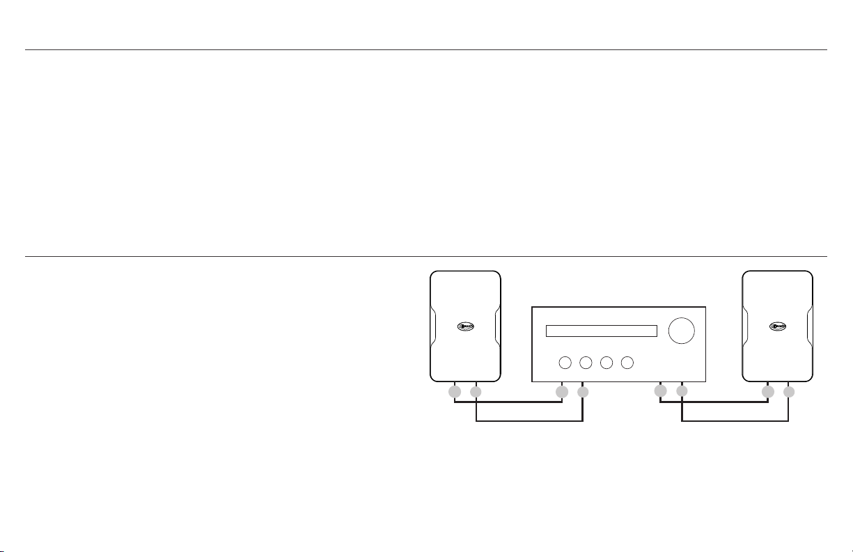
POTÊNCIA RECOMENDADA DO RECEIVER/AMPLIFICADOR PARA USO COM AS CAIXAS ACÚSTICAS KLIPSCH CP
Uma caixa acústica pode ser danificada quando a potência é
excessiva e, com a mesma facilidade, também pode ser danificada
quando a potência é insuficiente. Como regra geral, quando o
volume de um receiver/amplificador é aumentado para além da
“metade” (ou posição das “12 horas” em um botão de volume
graduado), o receiver/amplificador começa a trabalhar além de
sua capacidade, enviando distorção prejudicial que pode danificar
qualquer caixa acústica, independente do valor nominal de watts
que ela possa aceitar. Isso se aplica a qualquer combinação de caixa
acústica e receiver/amplificador. A potência recomendada para sua
nova caixa acústica Klipsch CP depende do modelo:
CP-4: até 50 watts contínuos (por um período prolongado de
tempo); “picos” de 200 watts (descargas/sobrecargas muito curtas)
CP-6: até 75 watts contínuos (por um período prolongado de
tempo); “picos” de 300 watts (descargas/sobrecargas muito curtas)
CONEXÃO DAS CAIXAS ACÚSTICAS A UM AMPLIFICADOR/RECEIVER
Ao conectar as caixas acústicas a um amplificador/receiver,
verifique sempre se a polaridade da caixa acústica está
correta. O melhor som é obtido ligando o terminal positivo
(+) do amplificador/receiver ao terminal positivo (+) da caixa
acústica e o terminal negativo (-) do amplificador/receiver ao
terminal negativo (-) da caixa acústica. Os terminais da caixa
acústica CP são projetados para aceitar cabos com bitola de
até 16 AWG.
Um par de caixas acústicas Série CP da Klipsch de 8 ohms
pode ser conectado aos terminais para caixas acústicas
esquerdo/direito de qualquer amplificador/receiver de 8 ohm
como mostrado.
+
-
+
-
+
-
+
-
+
-
+
-
ONE PAIR TO
8Ω CAPABLE
AMP/RECEIVER
Right Channel Left Channel
+
-
+
-
+
-
+
-
PARALLEL WIRING TWO PAIRS TO
4Ω CAPABLE AMP/RECEIVER
Right Channels Left Channels
+
-
+
-
+
-
+
-
+
-
+
-
SERIES WIRING TWO PAIRS TO
16Ω CAPABLE AMP/RECEIVER
Right Channels Left Channels
R
+
L
+
_
_
R
+
L
+
_
_
SPK A SPK B
Amp/Receiver Rear Amp/Receiver Front
SPK A SPK B
Um par para
amplificador/receiver com
capacidade de 8 ohm
Canal direito Canal esquerdo

SE DESEJAR USAR DOIS PARES DE CAIXAS ACÚSTICAS
KLIPSCH SÉRIE CP EM UM AMPLIFICADOR/RECEIVER,
RECOMENDAMOS UM DE DOIS MÉTODOS:
Método 1 (preferencial): Se o amplificador/receiver tiver terminais
para caixas acústicas A e B, conecte um par no A e outro no B.
Dependendo da capacidade do amplificador/receiver, é possível
reproduzir o som usando os pares de caixas acústicas A e B juntos
ou separadamente, ou somente o par de caixas acústicas A OU o
par de caixas acústicas B.
Método 2: SE O AMPLIFICADOR/RECEIVER TIVER
CLASSIFICAÇÃO DE 4 OHMS OU MENOS, conecte os cabos
em paralelo, como mostrado, a partir dos terminais para
caixas acústicas direito e esquerdo do amplificador/receiver.
O amplificador/receiver pode gerar mais potência para as
caixas acústicas desta maneira (verifique as especificações do
amplificador/receiver).
Conexão em série de dois pares a um amplificador/receiver: Em
vez de uma conexão em paralelo, usar uma conexão em série,
como mostrado, faz com que o amplificador/receiver trabalhe com
16 ohms, mas isso geralmente corta pela metade a potência que
chega a cada uma das caixas acústicas.
Caso esteja usando um receiver surround (7/9/11), PODE SER
que o receiver permita a conexão de um par adicional de caixas
acústicas a canais surround não utilizados para uso em outra
área de audição ou tenha um recurso de “Zona 2” para conectar
as caixas acústicas adicionais (consulte o manual do receiver).
Uso de comutador externo de caixas acústicas: Vários tipos de
caixas de seleção disponíveis permitem a conexão de vários pares
de caixas acústicas a um amplificador/receiver e permitem alternar
entre eles. Alguns modelos permitem a reprodução simultânea em
dois pares de caixas acústicas. (Consulte o revendedor de produtos
de áudio local para verificar a disponibilidade).
+
-
+
-
+
-
+
-
+
-
+
-
ONE PAIR TO
8Ω CAPABLE
AMP/RECEIVER
Right Channel Left Channel
+
-
+
-
+
-
+
-
PARALLEL WIRING TWO PAIRS TO
4Ω CAPABLE AMP/RECEIVER
Right Channels Left Channels
+
-
+
-
+
-
+
-
+
-
+
-
SERIES WIRING TWO PAIRS TO
16Ω CAPABLE AMP/RECEIVER
Right Channels Left Channels
R
+
L
+
_
_
R
+
L
+
_
_
SPK A SPK B
Amp/Receiver Rear Amp/Receiver Front
SPK A SPK B
CONEXÃO DAS CAIXAS ACÚSTICAS A UM AMPLIFICADOR/RECEIVER
+
-
+
-
+
-
+
-
+
-
+
-
ONE PAIR TO
8Ω CAPABLE
AMP/RECEIVER
Right Channel Left Channel
+
-
+
-
+
-
+
-
PARALLEL WIRING TWO PAIRS TO
4Ω CAPABLE AMP/RECEIVER
Right Channels Left Channels
+
-
+
-
+
-
+
-
+
-
+
-
SERIES WIRING TWO PAIRS TO
16Ω CAPABLE AMP/RECEIVER
Right Channels Left Channels
R
+
L
+
_
_
R
+
L
+
_
_
SPK A SPK B
Amp/Receiver Rear
Amp/Receiver Front
SPK A SPK B
+
-
+
-
+
-
+
-
+
-
+
-
ONE PAIR TO
8Ω CAPABLE
AMP/RECEIVER
Right Channel Left Channel
+
-
+
-
+
-
+
-
PARALLEL WIRING TWO PAIRS TO
4Ω CAPABLE AMP/RECEIVER
Right Channels Left Channels
+
-
+
-
+
-
+
-
+
-
+
-
SERIES WIRING TWO PAIRS TO
16Ω CAPABLE AMP/RECEIVER
Right Channels Left Channels
R
+
L
+
_
_
R
+
L
+
_
_
SPK A SPK B
Amp/Receiver Rear Amp/Receiver Front
SPK A SPK B
MÉTODO 2
MÉTODO 1
Ligação em série de dois pares
ao amplificador/receiver com
capacidade nominal de 16 ohm
Painel traseiro do
amplificador/receiver
Painel frontal do
amplificador/receiver
Caixa acústica A
Caixa acústica B
Caixa acústica A Caixa acústica B
Canal esquerdoCanal direito
Canal esquerdoCanal direito

SUGESTÃO DE POSICIONAMENTO DAS CAIXAS ACÚSTICAS
X
X
X
House
Mount Speakers horizontal
under roof eaves and point
down towards deck
Speakers disperse sound 90°
to cover whole deck evenly
EXEMPLO DE POSICIONAMENTO
EM SALA ESTÉREO
CAIXA ACÚSTICA INSTALADA EM PAREDE
EXEMPLO DE POSICIONAMENTO EM AMBIENTE COMO
CAIXAS ACÚSTICAS SURROUND
Caixas acústicas com distância entre si (X) igual à
distância em relação à principal posição de audição
Surround 5.1: 2 caixas acústicas laterais
Surround 7.1: 2 caixas acústicas laterais/2 traseiras
[todas as unidades de 1,5 a 2 m (5 a 6 pés) acima do piso]

X
X
X
House
Mount Speakers horizontal
under roof eaves and point
down towards deck
Speakers disperse sound 90°
to cover whole deck evenly
SUGESTÃO DE POSICIONAMENTO DAS CAIXAS ACÚSTICAS
Se as caixas acústicas estiverem
cobrindo uma grande área de audição
(p. ex., um pátio/deck amplo) pode ser
possível enviar um sinal mono (canal
E+D) para ambas as caixas acústicas
para que todos os ouvintes ouçam
tudo, mesmo se estiverem longe de
uma delas. Consulte o manual do
amplificador/receiver para ver se ele
permite isso.
(Se for instalar as caixas acústicas CP ao ar
livre, recomendamos que as proteja contra a
exposição direta à chuva, etc., instalando-as
sob beirais ou outro tipo de cobertura).
Outras dicas de instalação/posicionamento:
• Instalar uma caixa acústica em um canto entre paredes ou
entre a parede e o teto aumenta sua resposta de graves e
a intensidade.
• Certifique-se de que a caixa acústica não esteja instalada ou
posicionada onde haja uma obstrução que bloqueie o som.
• Direcionar a caixa acústica para a principal área de
audição reduz as reflexões sonoras das paredes e tetos e
melhora a qualidade do som.
• Quando a área a ser coberta for ampla, como um deck ou
pátio, é possível enviar um sinal mono (canal esquerdo
+ direito) por cada caixa acústica em vez de um sinal
estéreo, se o amplificador/receiver permitir. Assim, se os
ouvintes estiverem espalhados, conseguirão ouvir todas
as músicas.
Instale as caixas acústicas na posição
horizontal sob os beirais do telhado e
viradas para baixo, na direção do deck
As caixas acústicas distribuem
o som a 90° para cobrir
uniformemente todo o deck
Casa

CONTEÚDO DA EMBALAGEM
Acústicas (x2) Suportes (x2) Grade (x2) Parafusos (x4) Modelo Ferramenta de
Remoção da Grade
Mount Wall Bracket Template for CP-4/4T
MAKE SURE TEMPLATE IS LEVEL BEFORE DRILLING PILOT HOLES!
Horizontal
Pilot Hole
Vertical
Pilot Hole
Vertical
Pilot Hole
Horizontal
Pilot Hole
MAKE SURE TEMPLATE IS LEVEL
BEFORE DRILLING PILOT HOLES!
To mount speaker HORIZONTALLY UP in ceiling/wall corner putting bracket on wall
put THIS SIDE on wall flush against ceiling and mark horizontal pilot holes
To mount speaker vertically in corner PUTTING
BRACKET ON LEFT WALL against corner put THIS SIDE
flush in corner on left wall and mark vertical pilot holes
To mount speaker vertically in corner PUTTING
BRACKET ON RIGHT WALL against corner put
THIS SIDE flush in corner on left wall and mark
vertical pilot holes
KLIPSCH SÉRIE CP
Agradecemos sua preferência pelas caixas acústicas Klipsch Série
CP! Elas são projetadas para suportar os rigores do uso ao ar livre
e também complementar qualquer decoração interior como um par
de caixas acústicas estéreo ou surround em um sistema de cinema
em casa. O suporte de parede exclusivo fornecido permite a fácil
instalação horizontal ou vertical em parede, além da instalação
discreta alinhada em um canto para um visual altamente estético
que amplifica a reprodução de graves. Outra opção é a colocação
em prateleira ou mesa. A exclusiva corneta Tractrix® de 90° x 90°
da Klipsch não só proporciona cobertura controlada, reduzindo
a reflexão sonora que prejudica a qualidade geral do som, como
também produz mais som com o mesmo nível de potência de entrada
em comparação com outros designs. Os woofers de longo alcance
têm saídas frontais para reproduzir graves coesos e musicais,
independente de onde as caixas estejam instaladas ou colocadas.

DIMENSÕES DAS CAIXAS ACÚSTICAS COM/SEM OS SUPORTES INCLUÍDOS
CP-4
CP-6
Se for instalar as caixas acústicas na parede, passe o cabo da caixa acústica por trás da parede até
os pontos de instalação (se desejado)
Se for instalá-las na parede com suportes, também será necessário:
a) Um nível
b) Um lápis
c) Uma chave de fenda Phillips (tamanho 2)
d) Dois parafusos de cabeça abaulada número 10 ou 12 de 2,5 a 3 polegadas (6,4 a 7,6 cm) para
prender cada caixa acústica em viga de parede OU buchas de fixação para paredes sem vigas
com capacidade mínima de 10 lb (5 kg).
ANTES DE INSTALAR/CONECTAR AS CAIXAS ACÚSTICAS
5.5”
(14.0cm)
8.8”
(22.4cm)
7.2”
(18.3cm)
5.5”
(14.0cm)
4.7”
(11.9cm)
7.0 ”
(17.8cm)
11.0”
(27.9cm)
9.4”
(23.9cm)
6.9”
(17.5cm)
6.1”
(15.5cm)
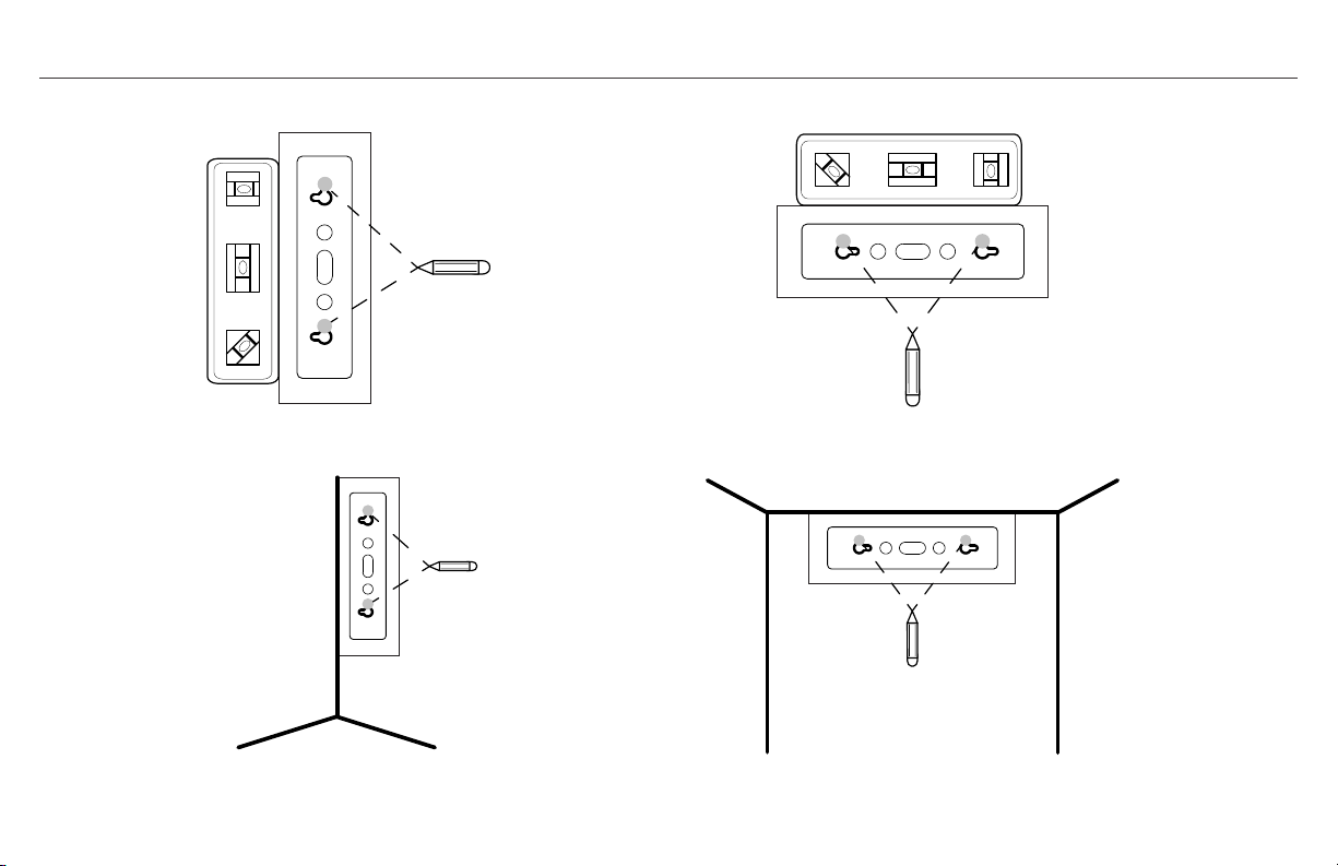
ETAPA 1
OU
Escolha a localização da caixa acústica e passe o cabo da caixa acústica até o local. Use o modelo
fornecido e um nível para marcar os locais dos furos do suporte onde a caixa acústica será instalada.
Instalação típica em parede com o suporte fornecido
Instalação em canto entre paredes ou entre teto e parede com o suporte fornecido
V
V
H H
V
V
H H
V
V
H H
V
V
H H
V
V
H H
V
V
H H
V
V
H H
V
V
H H
OU

ETAPA 2
Rimuovere il coperchio terminale di gomma dalla parte anteriore dell’altoparlante e
spingere il cavo attraverso il canale centrale sulla parte posteriore dell’altoparlante
finché non fuoriesce dalla parte anteriore dove si è rimosso il coperchio.
Cobertura dos terminais
Canal do cabo da caixa
acústica
Speaker
Wires
OR

ETAPA 2
SE USAR O SUPORTE FORNECIDO
A. Passe o cabo para a caixa acústica pelo orifício atrás do
suporte e prenda o suporte na parede.
B. Deslize parcialmente a caixa acústica nos braços do suporte e
passe o cabo de trás para a frente.
C.
Para manter a caixa acústica no suporte durante o ajuste, use
uma chave de fenda Phillips e rosqueie parcialmente os parafusos
frontais superior e inferior do suporte (2 a 3 voltas) e, em seguida,
puxe com cuidado a caixa acústica para a posição de retenção, 3/4
ao longo do suporte.
D. COM A CAIXA ACÚSTICA PUXADA PARA FORA ATÉ A
PRIMEIRA POSIÇÃO DE “RETENÇÃO” NO SUPORTE, coloque a
caixa acústica no ângulo desejado na parede.
Speaker
Wires
OR
A.
B.
C. D.
Speaker
Wires
OR
Speaker
Wires
OR
Speaker
Wires
OR
oDeR
CABOS PARA CAIXA
ACÚSTICA
Use parafusos de cabeça
abaulada número 10 ou 12, de
2,5 a 3” (6,4 a 7,6 cm)

45˚
45˚
45˚
WALL
45˚
CEILING OR WALL
45˚
45˚
45˚
WALL
45˚
CEILING OR WALL
45˚
45˚
45˚
WALL
45˚
CEILING OR WALL
45˚
45˚
45˚
WALL
45˚
CEILING OR WALL
45˚
45˚
45˚
WALL
45˚
CEILING OR WALL
OU
PAREDE
PAREDE
TETO OU PAREDE
PAREDE
OU

ETAPA 3
A. Conecte os cabos para a caixa acústica aos terminais na caixa
acústica com uma chave de fenda ou furadeira AJUSTADA
PARA O MENOR TORQUE COM UMA PONTA PHILLIPS NÚMERO
2. Observe a polaridade correta. Geralmente, o fio vermelho
é positivo (+) e o preto é negativo (–). Não importa qual cabo
é conectado ao terminal positivo ou negativo, desde que as
conexões sejam coerentes em todas as caixas acústicas que
fazem parte do mesmo sistema. Verifique se ambos os cabos
estão embutidos no canal e reinstale a cobertura dos terminais.
SE USAR O SUPORTE FORNECIDO
B. Assim que a caixa acústica estiver na posição desejada,
empurre-a totalmente para trás ao longo dos braços do suporte
até que fique alinhada com as coberturas do suporte e aperte
totalmente os dois parafusos inseridos para fixar a unidade.
Exemplo de seleção do
menor torque da furadeira
A.
B.
1 2 3 4 5
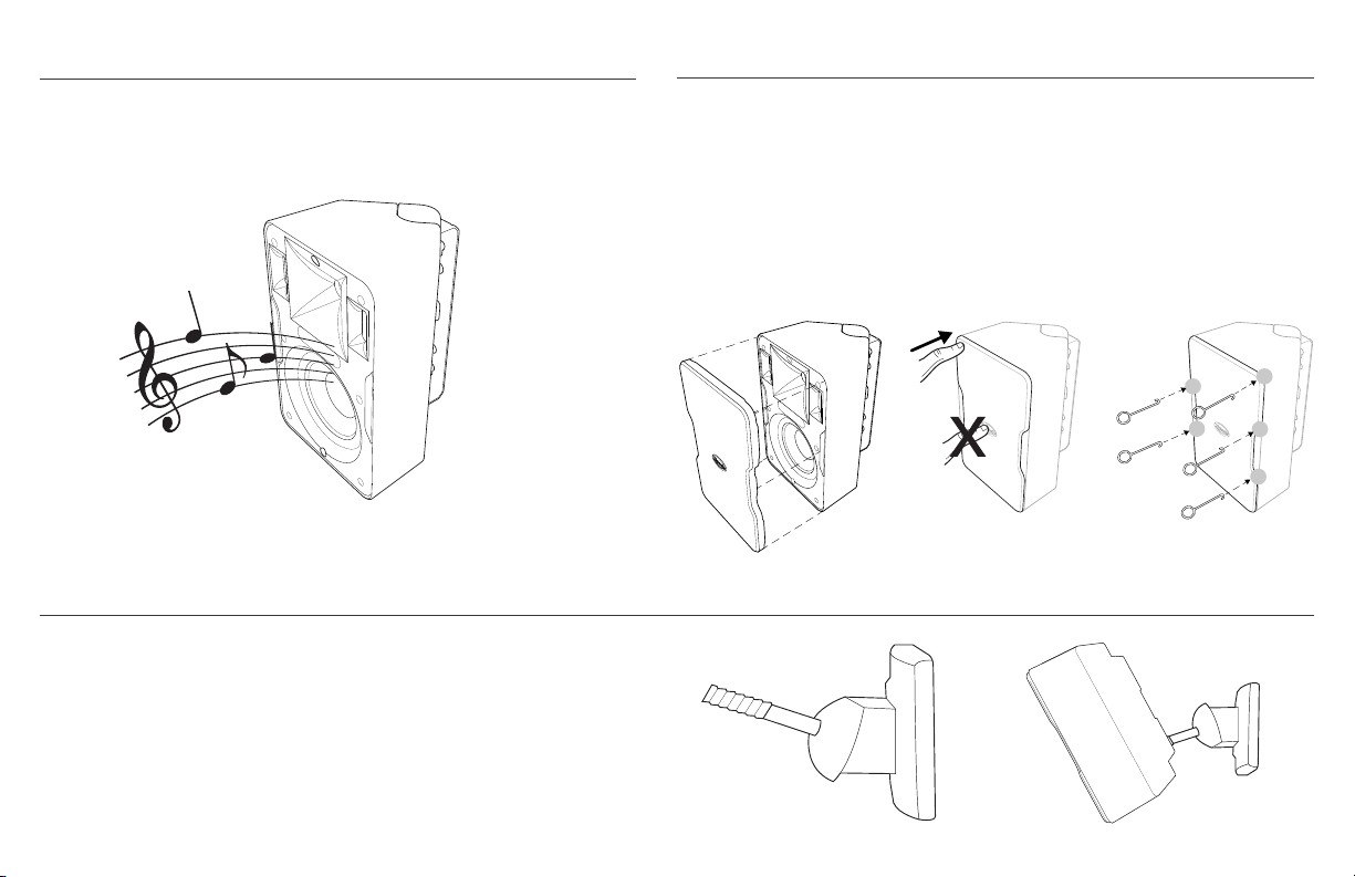
ETAPA 4
USO DE SUPORTES DE INSTALAÇÃO DIFERENTES DOS FORNECIDOS
TESTE O SOM: Reproduza música na caixa acústica para verificar
se as conexões estão firmes e a polaridade está correta.
ETAPA 5
Assim que a caixa acústica estiver na posição final e tiver sido
testada, instale a grade pressionando-a no canal que circunda a parte
frontal da caixa acústica.
*REMOÇÃO DA GRADE DA CAIXA ACÚSTICA: Insira a ferramenta de remoção da grade
fornecida em um dos cantos superiores e puxe com cuidado para fora. Repita esse
procedimento em um canto próximo ao primeiro e, em seguida, retire a grade gentilmente
com as mãos. OBSERVAÇÃO: A grade é projetada para se encaixar sem folgas na caixa
acústica e permanecer presa e firme. A remoção/recolocação contínua da grade pode fazer
com que fique frouxa e sujeita a vibrações ou deslizamento.
Todas as caixas acústicas Série CP têm um orifício de 1/4”, 20 roscas,
na parte inferior traseira para conexão a outro suporte compatível.
3
2
4
5
1
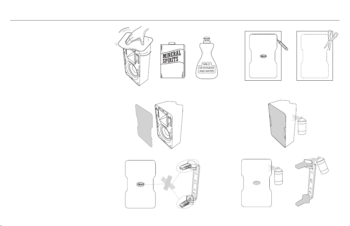
PINTURA DAS CAIXAS ACÚSTICAS
Pinte as caixas acústicas e as coberturas
superior/inferior dos suportes
separadamente.
1. Primeiro, limpe a superfície e as
coberturas superior e inferior do
suporte da caixa acústica com
solvente ou detergente neutro e água.
2. Em seguida, crie uma proteção
de pintura para ser colocada na
frente da caixa acústica (sonofletor)
traçando em papelão não poroso o
contorno da grade da caixa acústica e
recortando-o na linha traçada.
3. Coloque a proteção de papelão
na frente da caixa acústica (sobre
o sonofletor), certificando-se de
também cobrir o canal de encaixe da
grade; prenda com fita dupla face.
Não coloque fita adesiva no woofer.
Proteja ao redor das coberturas
superior/inferior do suporte,
certificando-se de não pintar o braço
do suporte e o mecanismo giratório.
Proteja o logotipo na frente da grade.
4. Use tinta spray para plástico e pinte
a caixa, as coberturas do suporte e
a frente da grade. Certifique-se de
não cobrir os orifícios da grade. Deixe
todas as peças secarem antes de
montar novamente a caixa acústica.
1. 2.
3.
4.
AGUARRÁS
MINERAL
ÁGUA +
DETERGENTE
NEUTRO

ESPECIFICAÇÕES DA KLIPSCH CP-4 ESPECIFICAÇÕES DA KLIPSCH CP-6
RESPOSTA DE FREQUÊNCIA
1
80 Hz a 22 kHz +3/-6 dB
POTÊNCIA MÁXIMA PERMISSÍVEL
2
50 W (pico de 200)
SENSIBILIDADE
3
94 dB a 1 W/1 m
IMPEDÂNCIA NOMINAL 8 ohm
TWEETER Tweeter com cúpula de alumínio de 1,9
cm (0,75")
CORNETA DE ALTA FREQUÊNCIA Corneta Tractrix® 90° X 90°
WOOFER
Woofer de longo alcance de 8,9 cm (3,5")
FREQUÊNCIA DE CROSSOVER 3,2 kHz/12 dB por oitava
TIPO DE CAIXA Refletor de graves mediante duas
aberturas com saídas frontais
PESO 2,2 kg (4,8 lb)
DIMENSÕES
22,4 cm (8,8") de altura x 14,0 cm (5,5")
de largura x 11,9 cm (4,7") de profundidade
DIMENSÕES COM SUPORTE DE PAREDE
22,4 cm (8,8") de altura x 14,0 cm (5,5")
de largura x 14,0cm (5,5") de profundidade
ACABAMENTOS Caixa e grade brancas/pretas
BITOLA DE CABO COMPATÍVEL 16
FABRICAÇÃO A PARTIR DE 2014
1
Câmara anecóica de 3 m
2
Ruído rosa filtrado segundo IEC 268-5 com fator de crista de 6 dB
3
SPL a 1 m, anecóica com entrada de 2,83 V
RESPOSTA DE FREQUÊNCIA
1
70 Hz a 22 kHz +3/-6 dB
POTÊNCIA MÁXIMA PERMISSÍVEL
2
75 W (pico de 300)
SENSIBILIDADE
3
94 dB a 1 W/1 m
IMPEDÂNCIA NOMINAL 8 ohm
TWEETER Tweeter com cúpula de alumínio de 1,9
cm (0,75")
CORNETA DE ALTA FREQUÊNCIA Corneta Tractrix® 90° X 90°
WOOFER
Woofer de longo alcance de 13,3 cm (5,25")
FREQUÊNCIA DE CROSSOVER 3 kHz/12 dB por oitava
TIPO DE CAIXA Refletor de graves mediante duas
aberturas com saídas frontais
PESO 2,6 kg (5,8 lb)
DIMENSÕES
27,9 cm (11,0") de altura x 17,8 cm (7,0") de
largura x 15,5 cm (6,1") de profundidade
DIMENSÕES COM SUPORTE DE PAREDE
27,9 cm (11,0") de altura x 17,8 cm (7,0") de
largura x 17,5 cm (6,9") de
profundidade
ACABAMENTOS Caixa e grade brancas/pretas
BITOLA DE CABO COMPATÍVEL 16
FABRICAÇÃO A PARTIR DE 2014
1
Câmara anecóica de 3 m
2
Ruído rosa filtrado segundo IEC 268-5 com fator de crista de 6 dB
3
SPL a 1 m, anecóica com entrada de 2,83 V

POTENZA RACCOMANDATA DEL RICEVITORE/AMPLIFICATORE PER L’USO CON GLI ALTOPARLANTI KLIPSCH CP
Un altoparlante può essere danneggiato tanto facilmente da
una potenza insufficiente quanto lo può essere da una potenza
eccessiva. Una regola generale è la seguente: quando si aumenta il
volume di un ricevitore/amplificatore oltre “la metà” (o posizione
“12:00” di un orologio immaginario quando il volume va regolato
con una manopola), il ricevitore/amplificatore inizia a funzionare
oltre i suoi valori nominali, generando una distorsione pericolosa
in grado di danneggiare qualsiasi altoparlante, indipendentemente
dalla potenza nominale che quest’ultimo può accettare. Questo
vale per qualsiasi combinazione di altoparlante e ricevitore/
amplificatore. La potenza raccomandata da usare con i nuovi
altoparlanti Klipsch CP dipende dal modello:
CP-4: fino a 50 watt continui (per un lungo periodo di tempo);
200 watt di picco (sovraccarichi molto brevi)
CP-6: fino a 75 watt continui (per un lungo periodo di tempo);
300 watt di picco (sovraccarichi molto brevi)
COLLEGAMENTO DEGLI ALTOPARLANTI A UN AMPLIFICATORE/RICEVITORE
Quando si collegano altoparlanti a un amplificatore/ricevitore,
accertarsi sempre della loro corretta polarità e di ottenere il
suono ottimale collegando il terminale positivo (+) e quello
negativo (-) dell’amplificatore/ricevitore rispettivamente al
terminale positivo (+) e negativo (-) di ciascun altoparlante. I
terminali degli altoparlanti CP accettano cavi di diametro sino a
16 AWG (1,29 mm).
Una coppia di altoparlanti Klipsch serie CP, 8 ohm, può essere
collegata ai corrispondenti terminali sinistro/destro di qualsiasi
amplificatore/ricevitore con impedenza nominale di 8 ohm
come illustrato.
+
-
+
-
+
-
+
-
+
-
+
-
ONE PAIR TO
8Ω CAPABLE
AMP/RECEIVER
Right Channel Left Channel
+
-
+
-
+
-
+
-
PARALLEL WIRING TWO PAIRS TO
4Ω CAPABLE AMP/RECEIVER
Right Channels Left Channels
+
-
+
-
+
-
+
-
+
-
+
-
SERIES WIRING TWO PAIRS TO
16Ω CAPABLE AMP/RECEIVER
Right Channels Left Channels
R
+
L
+
_
_
R
+
L
+
_
_
SPK A SPK B
Amp/Receiver Rear Amp/Receiver Front
SPK A SPK B
Una coppia a un
amplificatore/ricevitore
da 8 ohm
Canale destro Canale sinistro

SE SI DESIDERA USARE DUE COPPIE ODI ALTOPARLANTI
KLIPSCH SERIE CP CON UN AMPLIFICATORE/RICEVITORE, SI
CONSIGLIA UNO DEI DUE METODI SEGUENTI:
Metodo 1 (preferibile) Se l’amplificatore/ricevitore è dotato di
terminali sia per gli altoparlanti del set A che per quelli del set
B, collegarne una coppia al set A e una al set B. A seconda della
potenza dell’amplificatore/ricevitore si possono usare le coppie
A e B insieme o separatamente, ovvero solo la coppia A OPPURE
solo la coppia B.
Metodo 2 SE L’IMPEDENZA NOMINALE DELL’AMPLIFICATORE/
RICEVITORE È PARI A 4 OHM O MENO, collegare i cavi in
parallelo, come illustrato, ai terminali per altoparlante destro
e sinistro dell’amplificatore/ricevitore, che in questo modo può
erogare più potenza agli altoparlanti (controllare i dati tecnici
dell’amplificatore/ricevitore).
Collegamento in serie di due coppie di altoparlanti a un
amplificatore/ricevitore: anziché ricorrere a un collegamento
in parallelo, con un collegamento in serie come illustrato
l’amplificatore/ricevitore funziona a 16 ohm ma in genere si
dimezza la potenza applicata a ciascuno degli altoparlanti.
Se si usa un ricevitore surround (canale 7/9/11), il ricevitore
POTREBBE consentire di collegare un’ulteriore coppia di
altoparlanti a canali surround inutilizzati per l’uso in un’area di
ascolto diversa o potrebbe avere una funzionalità “Zona 2” per
il collegamento di tali altoparlanti (consultare il manuale del
ricevitore).
Uso di un commutatore per altoparlanti esterno: molti tipi di
commutatori disponibili consentono di collegare più coppie di
altoparlanti a un amplificatore/ricevitore e di selezionare la coppia
desiderata. Alcuni modelli consentono l’uso simultaneo di due coppie
di altoparlanti (controllare la disponibilità presso il rivenditore di
impianti audio).
+
-
+
-
+
-
+
-
+
-
+
-
ONE PAIR TO
8Ω CAPABLE
AMP/RECEIVER
Right Channel Left Channel
+
-
+
-
+
-
+
-
PARALLEL WIRING TWO PAIRS TO
4Ω CAPABLE AMP/RECEIVER
Right Channels Left Channels
+
-
+
-
+
-
+
-
+
-
+
-
SERIES WIRING TWO PAIRS TO
16Ω CAPABLE AMP/RECEIVER
Right Channels Left Channels
R
+
L
+
_
_
R
+
L
+
_
_
SPK A SPK B
Amp/Receiver Rear Amp/Receiver Front
SPK A SPK B
COLLEGAMENTO DEGLI ALTOPARLANTI A UN AMPLIFICATORE/RICEVITORE
+
-
+
-
+
-
+
-
+
-
+
-
ONE PAIR TO
8Ω CAPABLE
AMP/RECEIVER
Right Channel Left Channel
+
-
+
-
+
-
+
-
PARALLEL WIRING TWO PAIRS TO
4Ω CAPABLE AMP/RECEIVER
Right Channels Left Channels
+
-
+
-
+
-
+
-
+
-
+
-
SERIES WIRING TWO PAIRS TO
16Ω CAPABLE AMP/RECEIVER
Right Channels Left Channels
R
+
L
+
_
_
R
+
L
+
_
_
SPK A SPK B
Amp/Receiver Rear
Amp/Receiver Front
SPK A SPK B
+
-
+
-
+
-
+
-
+
-
+
-
ONE PAIR TO
8Ω CAPABLE
AMP/RECEIVER
Right Channel Left Channel
+
-
+
-
+
-
+
-
PARALLEL WIRING TWO PAIRS TO
4Ω CAPABLE AMP/RECEIVER
Right Channels Left Channels
+
-
+
-
+
-
+
-
+
-
+
-
SERIES WIRING TWO PAIRS TO
16Ω CAPABLE AMP/RECEIVER
Right Channels Left Channels
R
+
L
+
_
_
R
+
L
+
_
_
SPK A SPK B
Amp/Receiver Rear Amp/Receiver Front
SPK A SPK B
METODO 2
METODO 1
Collegamento in serie di due coppie
di altoparlanti a un amplificatore/
ricevitore con impedenza di 16 ohm
Parte posteriore
amplificatore/ricevitore
Parte anteriore amplificatore/
ricevitore
Altoparlante A Altoparlante B
Altoparlante A Altoparlante B
Canale sinistroCanale destro
Canale sinistroCanale destro
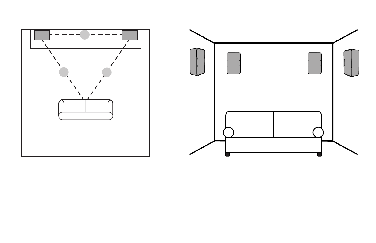
COLLOCAZIONE SUGGERITA DEGLI ALTOPARLANTI
X
X
X
House
Mount Speakers horizontal
under roof eaves and point
down towards deck
Speakers disperse sound 90°
to cover whole deck evenly
ESEMPIO DI COLLOCAZIONE IN UNA STANZA
COME ALTOPARLANTI STEREO
ALTOPARLANTE FISSATO ALLA PARETE
ESEMPIO DI COLLOCAZIONE IN UNA STANZA COME
ALTOPARLANTI SURROUND
Distanza tra gli altoparlanti (X) uguale alla
distanza dalla posizione di ascolto principale
5.1-Surround: 2 seitliche Lautsprecher
7.1-Surround: 2 seitliche / 2 hintere Lautsprecher
(alle Lautsprecher 1,5-2 m über dem Boden)

X
X
X
House
Mount Speakers horizontal
under roof eaves and point
down towards deck
Speakers disperse sound 90°
to cover whole deck evenly
COLLOCAZIONE SUGGERITA DEGLI ALTOPARLANTI
Se gli altoparlanti devono diffondere il
suono in un’area molto grande (come
una terrazza di notevoli dimensioni)
potrebbe essere possibile inviare
un segnale monofonico (canale sx
+ dx) a entrambi gli altoparlanti
affinché tutte le persone sentano
tutto anche se lontane da uno degli
altoparlanti. Consultare il manuale
dell‘amplificatore/ricevitore per
stabilire se ciò è possibile.
(Si raccomanda, quando si collocano
altoparlanti CP all’aperto, di proteggerli dalla
pioggia diretta ecc. fissandoli sotto le grondaie
o un altro tipo di copertura.)
A l t r i s u g g e r i m e n t i p e r l a c o l l o c a z i o n e o i l fi s s a g g i o :
• Fissando un altoparlante a un angolo tra due pareti o tra
una parete e il soffitto se ne aumenta la risposta ai bassi e
la sonorità.
• Accertarsi che l’altoparlante non sia collocato/fissato
dietro un ostacolo che ne blocca il suono.
• Orientando un altoparlante verso l’area principale di
ascolto si riducono le riflessioni dalle pareti o dal soffitto e
si migliora la qualità del suono.
• Quando si deve coprire un’area di grandi dimensioni, come
una terrazza, se l’amplificatore/ricevitore lo consente
si può inviare un segnale monofonico (canale sx + dx)
attraverso ciascun altoparlante anziché il segnale stereo
affinché le persone possano ascoltare tutta la musica
anche se sono sparpagliate.
Fissare gli altoparlanti in
orizzontale sotto le grondaie e
orientati verso il pavimento
Gli altoparlanti diffondono il
suono a 90° in modo uniforme
nell’intera area aperta
Abitazione
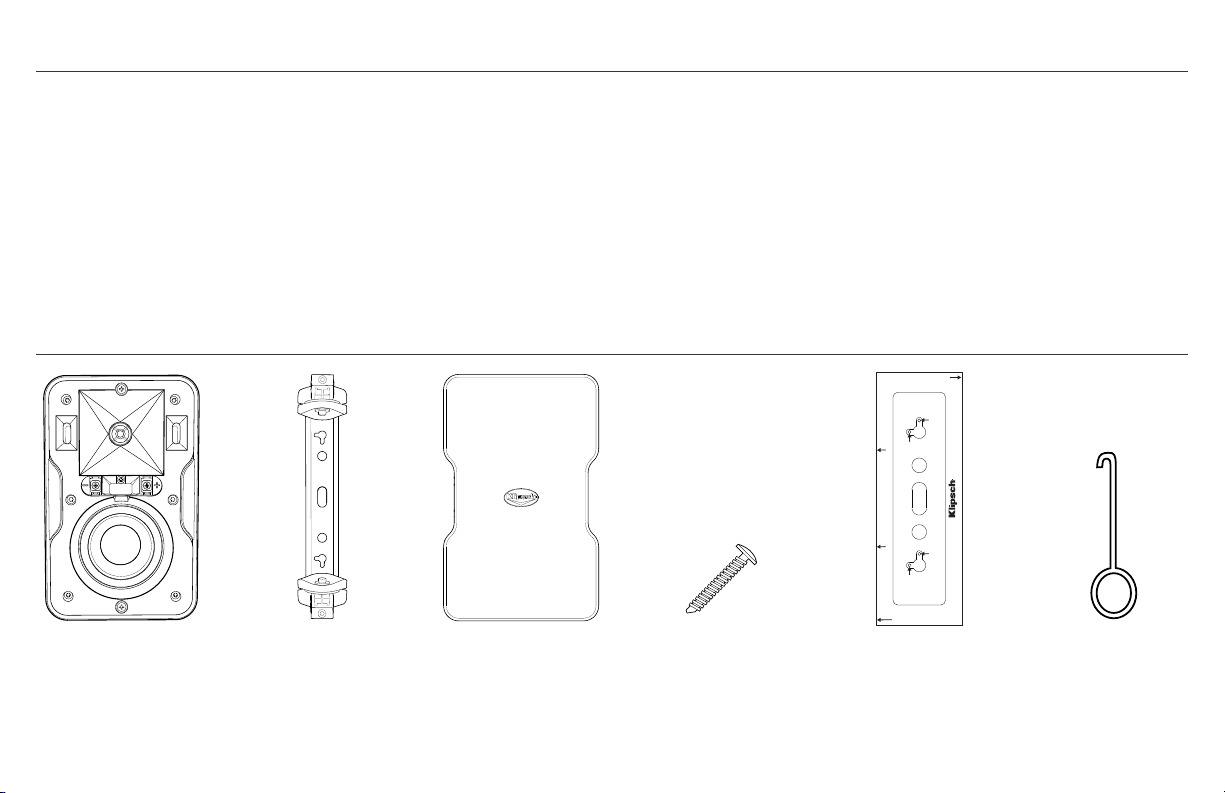
CONTENUTO DELLA CONFEZIONE
Altoparlanti (x2) Staffe (x2) Griglia (x2) Viti (x4) Dima Fornita Rimozione Griglia
Attrezzo
Mount Wall Bracket Template for CP-4/4T
MAKE SURE TEMPLATE IS LEVEL BEFORE DRILLING PILOT HOLES!
Horizontal
Pilot Hole
Vertical
Pilot Hole
Vertical
Pilot Hole
Horizontal
Pilot Hole
MAKE SURE TEMPLATE IS LEVEL
BEFORE DRILLING PILOT HOLES!
To mount speaker HORIZONTALLY UP in ceiling/wall corner putting bracket on wall
put THIS SIDE on wall flush against ceiling and mark horizontal pilot holes
To mount speaker vertically in corner PUTTING
BRACKET ON LEFT WALL against corner put THIS SIDE
flush in corner on left wall and mark vertical pilot holes
To mount speaker vertically in corner PUTTING
BRACKET ON RIGHT WALL against corner put
THIS SIDE flush in corner on left wall and mark
vertical pilot holes
KLIPSCH SERIE CP
Grazie per avere acquistato gli altoparlanti Klipsch serie CP! Questi
altoparlanti sono stati progettati sia per resistere alle condizioni
difficili dell’uso all’aperto sia per completare qualunque arredamento
di locali chiusi come coppia di diffusori stereo o surround in un
impianto Home Theater. Le esclusive staffe da parete, fornite,
consentono di fissarli facilmente in orizzontale o in verticale e anche
in uno spazio angusto, come un angolo, per ottenere un look molto
elegante ma anche un’uscita migliore ai bassi. Un’ulteriore scelta è
la collocazione su una mensola o su un tavolo. L’esclusiva tromba
Klipsch Tractrix® da 90°x 90° non solo offre copertura controllata,
riducendo le riflessioni che peggiorano la qualità complessiva del
suono, ma assicura anche un’uscita maggiore con la stessa potenza
d’ingresso rispetto ad altri design. I woofer ad ampia escursione
(long-throw) sono combinati con due aperture anteriori per creare
bassi nitidi e musicali indipendentemente dal punto in cui sono
collocati o fissati.

DIMENSIONI DEGLI ALTOPARLANTI CON/SENZA LE STAFFE FORNITE
CP-4
CP-6
Se si devono fissare gli altoparlanti a una parete, disporne i cavi dietro la parete stessa sino ai punti
di fissaggio (se si desidera)
Se si intende fissarli a una parete con staffe, occorrono anche:
a) Una livella
b) Una matita
c) Un cacciavite con testa a croce Phillips (n. 2)
d) Due viti a testa tronco-conica da 6,35 – 7,62 cm, n. 10 o 12 per il fissaggio ai montanti se la
parete è di legno OPPURE tasselli da almeno 5 kg se non sono disponibili montanti.
PRIMA DI PROCEDERE ALL’INSTALLAZIONE/CONNESSIONE DEGLI ALTOPARLANTI
5.5”
(14.0cm)
8.8”
(22.4cm)
7.2”
(18.3cm)
5.5”
(14.0cm)
4.7”
(11.9cm)
7.0 ”
(17.8cm)
11.0”
(27.9cm)
9.4”
(23.9cm)
6.9”
(17.5cm)
6.1”
(15.5cm)

1.
OPPURE
Scegliere il punto in cui collocare l’altoparlante e disporne il cavo sino a tale punto. Usare la dima
fornita e una livella per contrassegnare i punti in cui praticare i fori per la staffa dell’altoparlante.
Tipico fissaggio a parete con la staffa fornita
Se si eseguirà il fissaggio a un angolo tra due pareti o tra una parete e il soffitto con la staffa fornita
V
V
H H
V
V
H H
V
V
H H
V
V
H H
V
V
H H
V
V
H H
V
V
H H
V
V
H H
OPPURE

2.
Rimuovere il coperchio terminale di gomma dalla parte anteriore dell’altoparlante e
spingere il cavo attraverso il canale centrale sulla parte posteriore dell’altoparlante
finché non fuoriesce dalla parte anteriore dove si è rimosso il coperchio.
Coperchio terminale
Canale per cavo
altoparlante
Speaker
Wires
OR
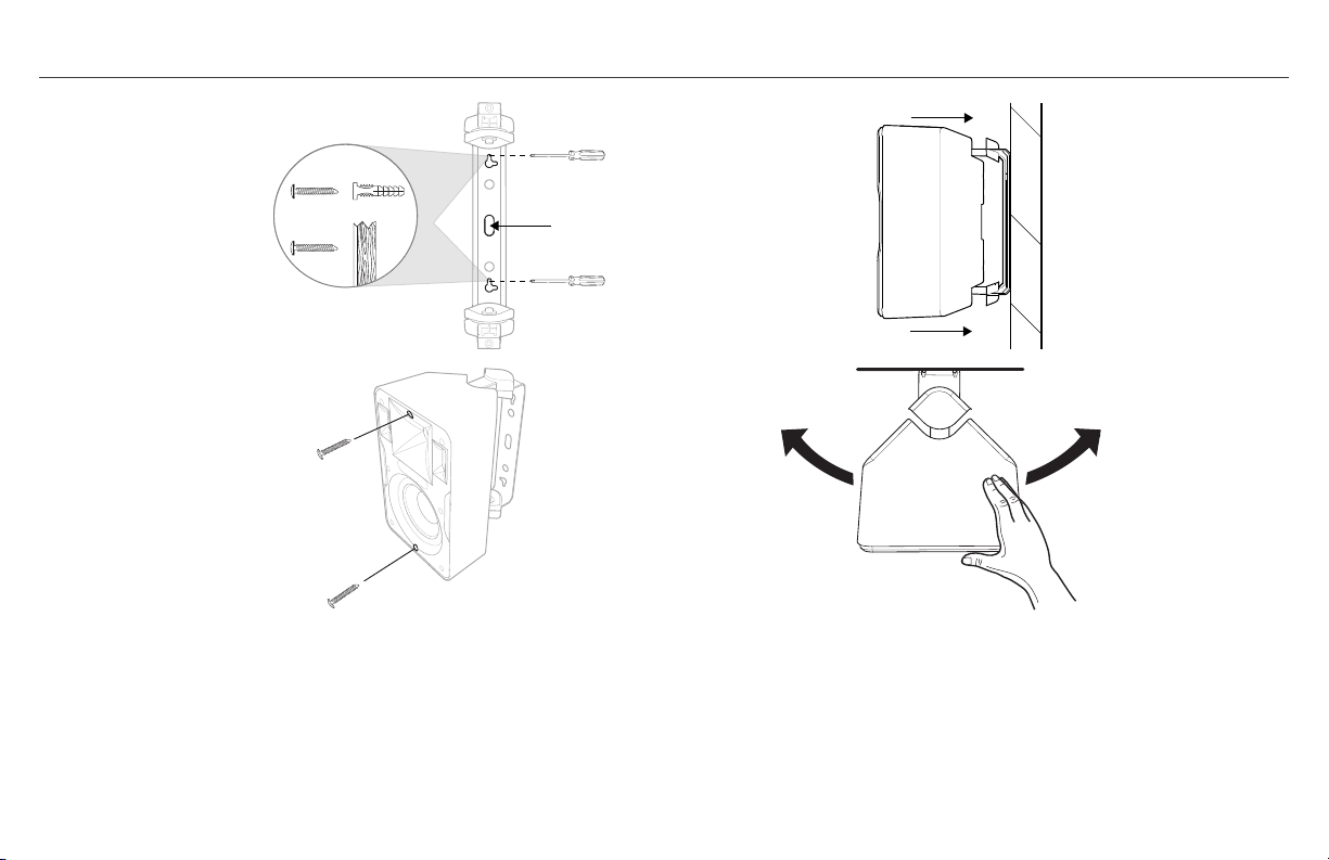
2.
SE SI USA LA STAFFA FORNITA
A. Fare passare il cavo dell’altoparlante attraverso il foro nella
parte posteriore della staffa e fissare quest’ultima alla parete.
B. Fare scorrere l’altoparlante parzialmente sui bracci della staffa
e fare passare il cavo lungo il canale dalla parte posteriore a
quella anteriore
C.
Per mantenere l’altoparlante sulla staffa mentre se ne regola
la posizione, avvitare parzialmente dalla parte anteriore con il
cacciavite Phillips le viti superiore/inferiore della staffa (2 – 3 giri),
quindi tirare in fuori con cautela l’altoparlante sino alla posizione di
arresto, a 3/4 sulla staffa.
D. CON L’ALTOPARLANTE ANCORA TIRATO IN FUORI ALLA PRIMA
POSIZIONE DI ARRESTO, regolare l’angolazione dell’altoparlante
come si desidera sulla parete.
Speaker
Wires
OR
A.
B.
C. D.
Speaker
Wires
OR
Speaker
Wires
OR
Speaker
Wires
OR
oDeR
CAVI ALTOPARLANTE
Usare viti a testa tronco-conica
n. 10 – 12, da 6,35 – 7,62 mm

45˚
45˚
45˚
WALL
45˚
CEILING OR WALL
45˚
45˚
45˚
WALL
45˚
CEILING OR WALL
45˚
45˚
45˚
WALL
45˚
CEILING OR WALL
45˚
45˚
45˚
WALL
45˚
CEILING OR WALL
45˚
45˚
45˚
WALL
45˚
CEILING OR WALL
OPPURE
PARETE
PARETE
SOFFITTO O PARETE
PARETE
OPPURE

3.
A. Collegare i cavi dell’altoparlante ai suoi terminali con il cacciavite
o USANDO UN TRAPANO REGOLATO SUL VALORE MINIMO DI
COPPIA E CON UNA PUNTA PHILIPS N. 2. Osservare la corretta
polarità. Normalmente, il cavo rosso corrisponde al positivo (+)
e il cavo nero al negativo (–). Non importa quale cavo è collegato
al terminale positivo o negativo purché le connessioni siano
coerenti su tutti gli altoparlanti nello stesso impianto. Accertarsi
che entrambi i cavi siano spinti all’interno della scanalatura e
riposizionare il coperchio terminale.
SE SI USA LA STAFFA FORNITA
B. Dopo aver posizionato l’altoparlante come desiderato, spingerlo
completamente indietro sui bracci della staffa finché non è a filo
con i coperchi della staffa e avvitare completamente le due viti
inserite per bloccarlo.
Esempio di trapano regolato
sulla coppia minima
A.
B.
1 2 3 4 5

4.
USO DI STAFFE DI FISSAGGIO DIVERSE DA QUELLE FORNITE
VERIFICA DEL SUONO: riprodurre della musica tramite
l’altoparlante per accertarsi che le connessioni siano salde e la
polarità sia giusta.
5.
Dopo che l’altoparlante è nella posizione finale e se ne è verificata la
funzionalità, fissare la griglia all’altoparlante premendola sul canale
lungo il perimetro della sua parte anteriore.
*RIMOZIONE DELLA GRIGLIA DELL’ALTOPARLANTE Inserire l’apposito attrezzo, fornito, in
un angolo superiore e con cautela tirarla in fuori. Ripetere su un angolo accanto al primo da
cui si è tirata in fuori la griglia, quindi staccarla gentilmente con la mano. NOTA. La griglia è
progettata in modo da rimanere ben fissata all’altoparlante combaciando. Se la si rimuove/
reinserisce continuamente, può allentarsi ed essere soggetta o vibrazioni o può scivolare.
Tutti gli altoparlanti serie CP hanno un inserto filettato n. 20, da
1/4”, sulla parte posteriore in basso, che ne permette il fissaggio a
un supporto differente purché compatibile.
3
2
4
5
1

VERNICIATURA DEGLI ALTOPARLANTI
Verniciare separatamente l’altoparlante e i
coperchi superiore/inferiore della staffa.
1. Anzitutto, pulire la cassa
dell’altoparlante e i coperchi
superiore/inferiore della staffa con
un solvente delicato o con acqua e un
detergente delicato.
2. Quindi creare una maschera da
verniciatura per la parte anteriore
(diaframma) dell’altoparlante
disegnando il profilo della griglia su un
foglio di carta più spessa, non porosa
e tagliando il foglio lungo il disegno.
3. Collocare la maschera di carta sulla
parte anteriore dell’altoparlante
(sopra il diaframma) accertandosi
che copra anche il canale della griglia
e fissandola con nastro biadesivo.
Non attaccare il nastro al woofer.
Coprire con una maschera i coperchi
superiore/inferiore della staffa,
facendo attenzione a non verniciarne
i bracci né lo snodo. Coprire con una
maschera il logo sulla parte anteriore
della griglia.
4. Usare vernice a spruzzo per plastica e
applicarla alla cassa dell’altoparlante,
ai coperchi della staffa e alla parte
anteriore della griglia. Accertarsi di
non spruzzarla sui fori della griglia.
Lasciare asciugare tutte le parti
prima di montare l’altoparlante.
1. 2.
3.
4.
ACQUARAGIA
MINERALE
DETERGENTE
DELICATO +
ACQUA

DATI TECNICI DEL KLIPSCH CP-4 DATI TECNICI DEL KLIPSCH CP-6
RISPOSTA IN FREQUENZA
1
80 Hz - 22 kHz +3/-6 dB
POTENZA MASSIMA
2
50 W (200 W di picco)
SENSIBILITÀ
3
91 dB a 1 watt/metro
IMPEDENZA NOMINALE 8 ohm
TWEETER Con cupola in alluminio da 1,9 cm
TROMBA PER ALTE FREQUENZE Tractrix® 90° x 90°
WOOFER IMG long-throw da 8,9 cm
FREQUENZA CROSSOVER 3,2 kHz 12 dB/ottava
TIPO DI CASSA Bass-reflex con due aperture anteriori
PESO 2,2 kg
DIMENSIONI 22,4 cm x 14,0 cm x 11,9 cm (A x L x P)
DIMENSIONI CON STAFFA DA PARETE
22,4 cm x 14,0 cm x 14.0 cm (A x L x P)
FINITURE Griglia e cassa colore nero/bianco
DIAMETRO DEI CAVI ACCETTATI 16 AWG (1,29 mm)
ANNO INIZIALE DI PRODUZIONE 2014
1
A 3 m in camera anecoica
2
IEC 268-5 Rumore rosa filtrato con fattore di cresta pari a 6 dB
3
SPL a 1 m in camera anecoica con ingresso di 2,83 V
RISPOSTA IN FREQUENZA
1
70 Hz - 22 kHz +3/-6 dB
POTENZA MASSIMA
2
75 W (300 W di picco)
SENSIBILITÀ
3
94 dB a 1 watt/metro
IMPEDENZA NOMINALE 8 ohm
TWEETER Con cupola in alluminio da 1,9 cm
TROMBA PER ALTE FREQUENZE Tractrix® 90° x 90°
WOOFER IMG long-throw da 13,3 cm
FREQUENZA CROSSOVER 3 kHz 12 dB/ottava
TIPO DI CASSA Bass-reflex con due aperture anteriori
PESO 2,6 kg
DIMENSIONI 27,9 cm x 17,8 cm x 15,5 cm (A x L x P)
DIMENSIONI CON STAFFA DA PARETE
27,9 cm x 17,8 cm x 17,5cm (A x L x P)
FINITURE Griglia e cassa colore nero/bianco
DIAMETRO DEI CAVI ACCETTATI 16 AWG (1,29 mm)
ANNO INIZIALE DI PRODUZIONE 2014
1
A 3 m in camera anecoica
2
IEC 268-5 Rumore rosa filtrato con fattore di cresta pari a 6 dB
3
SPL a 1 m in camera anecoica con ingresso di 2,83 V

建议 KLIPSCH CP 扬声器使用的接收器/放大器功率:
同功率太大一样,如果功率太低,扬声器也很容易损坏。 一般而言,当
接收器/放大器的音量超过“一半”(或音量旋钮上“12 点钟”位置)
时,无论扬声器的额定功率是多少瓦,接收器/放大器即开始超出其工
作能力,从而会产生导致扬声器损坏的有害失真。 对于任何扬声器和接
收器/放大器的组合,这一点都毋庸置疑。 您新购的 Klipsch CP 扬声
器的建议使用功率取决于扬声器型号:
CP-4:持续达 50 瓦(持续一段时间);峰值 200 瓦(短时脉冲群/浪涌)
CP-6:持续达 75 瓦(持续一段时间);峰值 300 瓦(短时脉冲群/浪涌)
扬声器与放大器/接收器的连接:
将扬声器与放大器/接收器连接时,始终确保扬声器的极性连接正
确。将放大器/接收器的正极 (+) 与扬声器的正极 (+) 连接,将
放大器/接收器的负极 (-) 与扬声器的负极 (-) 连接,以获得最
佳的音响效果。 根据设计,CP 扬声器端子能够支持高达 16 号
线规。
一对 8 欧姆 Klipsch CP 系列扬声器可以与任何额定值为 8 欧姆
的放大器/接收器(如图所示)的左/右扬声器端子连接。
+
-
+
-
+
-
+
-
+
-
+
-
ONE PAIR TO
8Ω CAPABLE
AMP/RECEIVER
Right Channel Left Channel
+
-
+
-
+
-
+
-
PARALLEL WIRING TWO PAIRS TO
4Ω CAPABLE AMP/RECEIVER
Right Channels Left Channels
+
-
+
-
+
-
+
-
+
-
+
-
SERIES WIRING TWO PAIRS TO
16Ω CAPABLE AMP/RECEIVER
Right Channels Left Channels
R
+
L
+
_
_
R
+
L
+
_
_
SPK A SPK B
Amp/Receiver Rear Amp/Receiver Front
SPK A SPK B
一对 8 欧姆放大器/接
收器
右声道 左声道
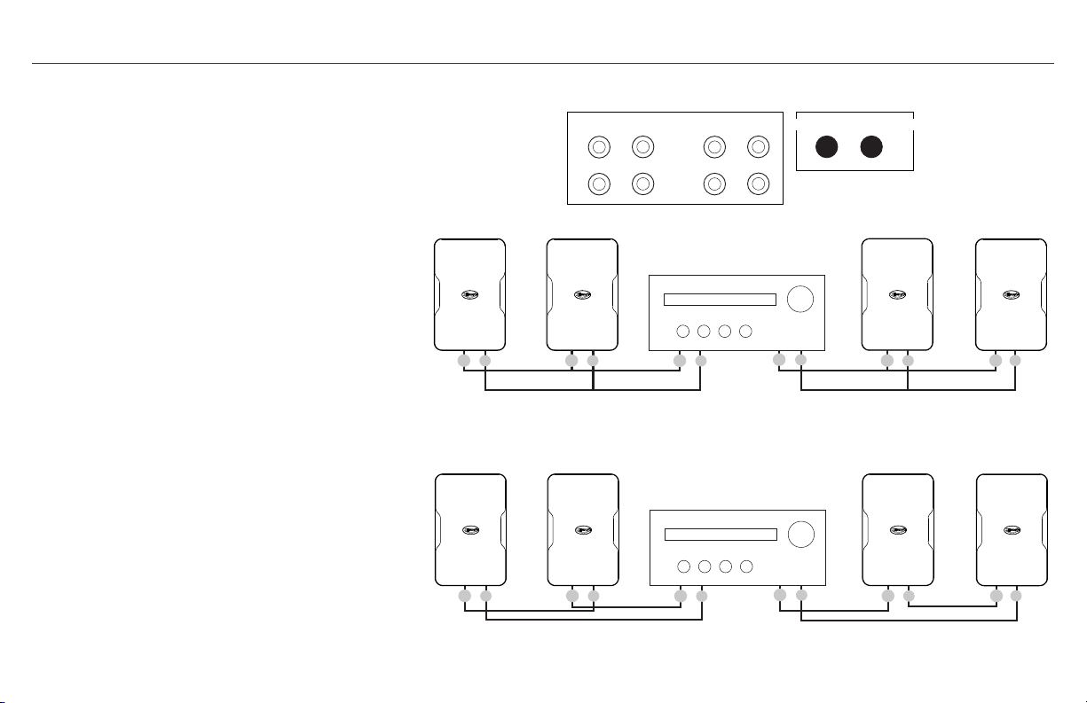
如果您想在单个放大器/接收器上使用两对 KLIPSCH CP
系列扬声器,我们建议您采用下列两种方法之一:
方法 1 (优选):如果您的放大器/接收器具有 A 和 B
两个扬声器端子,将一对扬声器与端子 A 连接,将另一
对与端子 B 连接。根据放大器/接收器的能力,您既可
选择同时播放两对扬声器,也可选择单独播放其中一对
扬声器。
方法 2:如果您的放大器/接收器的额定值为 4 欧姆或更
低,如图所示,从放大器/接收器的左/右扬声器端子进行
并联。 采用此方法,您的放大器/接收器也许能向扬声器
输出更高的功率(请检查放大器/接收器的技术规格)。
两对扬声器与单个放大器/接收器串联: 不采用并联,而
是采用串联(如图所示),使放大器/接收器的工作电阻
为 16 欧姆,这样通常可将每个扬声器的输入功率减半。
如果您使用环绕声(7/9/11 声道)接收器,则该接收器
也许可支持将一对额外的扬声器连接至未使用的环绕声
声道,以供在不同的聆听区使用;或者该接收器可能具
有“第 2 区”能力,支持与那些扬声器连接(具体请参
阅相应的接收器手册)。
- 使用外置扬声器转换开关:有几种类型的选择开关盒可
供选择,它们支持将多对扬声器连接至单个放大器/接收
器,还支持在多对扬声器之间进行切换。 其中某些型号
支持同时播放两对扬声器。 (有关可用性事宜,请参阅
相应的音响经销商资料。)
+
-
+
-
+
-
+
-
+
-
+
-
ONE PAIR TO
8Ω CAPABLE
AMP/RECEIVER
Right Channel Left Channel
+
-
+
-
+
-
+
-
PARALLEL WIRING TWO PAIRS TO
4Ω CAPABLE AMP/RECEIVER
Right Channels Left Channels
+
-
+
-
+
-
+
-
+
-
+
-
SERIES WIRING TWO PAIRS TO
16Ω CAPABLE AMP/RECEIVER
Right Channels Left Channels
R
+
L
+
_
_
R
+
L
+
_
_
SPK A SPK B
Amp/Receiver Rear Amp/Receiver Front
SPK A SPK B
扬声器与放大器/接收器的连接:
+
-
+
-
+
-
+
-
+
-
+
-
ONE PAIR TO
8Ω CAPABLE
AMP/RECEIVER
Right Channel Left Channel
+
-
+
-
+
-
+
-
PARALLEL WIRING TWO PAIRS TO
4Ω CAPABLE AMP/RECEIVER
Right Channels Left Channels
+
-
+
-
+
-
+
-
+
-
+
-
SERIES WIRING TWO PAIRS TO
16Ω CAPABLE AMP/RECEIVER
Right Channels Left Channels
R
+
L
+
_
_
R
+
L
+
_
_
SPK A SPK B
Amp/Receiver Rear
Amp/Receiver Front
SPK A SPK B
+
-
+
-
+
-
+
-
+
-
+
-
ONE PAIR TO
8Ω CAPABLE
AMP/RECEIVER
Right Channel Left Channel
+
-
+
-
+
-
+
-
PARALLEL WIRING TWO PAIRS TO
4Ω CAPABLE AMP/RECEIVER
Right Channels Left Channels
+
-
+
-
+
-
+
-
+
-
+
-
SERIES WIRING TWO PAIRS TO
16Ω CAPABLE AMP/RECEIVER
Right Channels Left Channels
R
+
L
+
_
_
R
+
L
+
_
_
SPK A SPK B
Amp/Receiver Rear Amp/Receiver Front
SPK A SPK B
方法 2
方法 1
将两对扬声器与 16欧姆放大器/接
收器串联
放大器/接收器背面
放大器/接收器前面
扬声器 A 扬声器 B
扬声器 A 扬声器 B
左声道右声道
左声道右声道

扬声器布置建议:
X
X
X
House
Mount Speakers horizontal
under roof eaves and point
down towards deck
Speakers disperse sound 90°
to cover whole deck evenly
立体声房间布置实例 壁挂式安装扬声器
环绕声扬声器室内布置实例
扬声器之间的距离 (X) 和扬声器与主要聆听区位置之间
的距离相同
5.1 环绕声: 两个旁置扬声器
7.1 环绕声: 两个旁置/两个后置扬声器
(所有扬声器距离地板的高度均为 5 英尺至 6 英尺 (1.5
米至 2 米))。

X
X
X
House
Mount Speakers horizontal
under roof eaves and point
down towards deck
Speakers disperse sound 90°
to cover whole deck evenly
扬声器布置建议:
如果扬声器覆盖很大的聆听区(即,大
面积庭院/地面),您也许能够同时将
单信号(左/右声道)传送至两个扬声
器,这样即使离其中一个扬声器很远,
所有听众都能清楚地听到任何声音。 请
参阅相应的放大器/接收器手册,以确
定是否支持该功能。
(建议在室外安装 CP 系列扬声器时,
通过安装屋檐或其
他他他他他
子,避免扬声
器遭受直接雨淋等影响。)
其他安装/布置提示:
• 将扬声器安装在角落或墙角/天花板角落可提高其低音响应和音量。
•
确保避免将扬声器安装/布置在障碍物的后面,否则会阻碍声音的
传播。
•
将扬声器对准主要聆听区可减少墙壁/天花板的反射,并可提高
音质。
• 当扬声器覆盖很大的聆听区(如庭院/地面)时,如果您的放大器/
接收器支持该功能,您可同时将单信号(左/右声道)传送至两个扬
声器,而不是传送立体声,这样即使听众相隔很远,大家都可将所
有音乐听得一清二楚。
将扬声器水平安装在屋檐下,向
下朝向地面。
扬声器将声音呈
90º
散播,均匀
覆盖整个地面。
房子

包装清单
(x2) (x2) (x2) (x4)
Mount Wall Bracket Template for CP-4/4T
MAKE SURE TEMPLATE IS LEVEL BEFORE DRILLING PILOT HOLES!
Horizontal
Pilot Hole
Vertical
Pilot Hole
Vertical
Pilot Hole
Horizontal
Pilot Hole
MAKE SURE TEMPLATE IS LEVEL
BEFORE DRILLING PILOT HOLES!
To mount speaker HORIZONTALLY UP in ceiling/wall corner putting bracket on wall
put THIS SIDE on wall flush against ceiling and mark horizontal pilot holes
To mount speaker vertically in corner PUTTING
BRACKET ON LEFT WALL against corner put THIS SIDE
flush in corner on left wall and mark vertical pilot holes
To mount speaker vertically in corner PUTTING
BRACKET ON RIGHT WALL against corner put
THIS SIDE flush in corner on left wall and mark
vertical pilot holes
KLIPSCH CP
感谢您选购 Klipsch CP 系列扬声器! 该系列扬声器的设计匠心独
具,既能在严酷的室外环境中使用,又能在家庭影院系统中作为立体声
对或环绕声扬声器,可为室内装饰锦上添花。 独特的随附壁挂支架便于
水平或垂直壁挂安装,甚至还适宜墙角隐藏式安装,不仅美观大方,而
且还能增加低音输出。 另外,还可将扬声器布置在架子或桌面上。 专
用的 Klipsch 90°x 90° Tractrix® 号角不仅能够提供可控的覆盖范围,
减少会损害总体音质的反射声,而且与其他设计相比,采用相同的功率
输入,却能获得更大的声音输出。 长冲程低音炮与前推端口相得益彰,
无论如何安装或布置,均能获得紧密的低音效果

扬声器尺寸(含/不含随附支架):
CP-4
CP-6
- 如果在墙壁上安装扬声器,请从墙壁后面将扬声器导线敷设至安装点(如果需要)
- 如果采用支架进行壁挂式安装,您还需要使用下列部件:
(a) 水平仪
(b) 铅笔
(c) 十字螺丝刀 (尺寸:2 号)
(d) 两个 10 号 或 12 号 2.5 英寸至 3 英寸(6.35 至 7.62 厘米)盘头螺钉,用于将扬声器安装至墙架
内柱;或者两个至少 10 磅(5 千克)墙锚,用于安装扬声器(如果墙架内柱不可用时)。
在扬声器安装/连接之前:
5.5”
(14.0cm)
8.8”
(22.4cm)
7.2”
(18.3cm)
5.5”
(14.0cm)
4.7”
(11.9cm)
7.0 ”
(17.8cm)
11.0”
(27.9cm)
9.4”
(23.9cm)
6.9”
(17.5cm)
6.1”
(15.5cm)

第 1 步
或
选择扬声器安装位置,并将扬声器导线敷设至该位置。 使用随附模板和水平仪标示即将安装扬声器的支
架孔位置。
典型的壁挂式安装(采用随附支架)
如果采用随附支架在墙壁/墙角或天花板/墙壁角落安装
V
V
H H
V
V
H H
V
V
H H
V
V
H H
V
V
H H
V
V
H H
V
V
H H
V
V
H H
或

第 2 步
从扬声器前部卸下橡胶端子盖,然后通过扬声器背部的中间槽前推扬声器导线,直到将导
线推至此前端子盖所在的扬声器前部。
端子盖
扬声器导线槽
Speaker
Wires
OR

第 2 步
如果使用随附支架
A.
通过支架背部的开孔敷设扬声器导线,然后将壁挂支架安装在墙壁上
B. 将扬声器部分滑入支架臂,并将导线从后往前敷设
C.
调整时为了将扬声器保持在支架上,使用十字螺丝刀将前面的顶部/底
部支架螺钉部分旋入(大约旋入 2 至 3 圈),然后向外轻拉扬声器,以
松开支架 3/4 处的位置。
D. 当拉出的扬声器仍然处于支架上第一个“停止”位置时,在墙壁上
将扬声器调整至所需的角度
Speaker
Wires
OR
A.
B.
C. D.
Speaker
Wires
OR
Speaker
Wires
OR
Speaker
Wires
OR
或
扬声器导线
使用 10 号至 12 号 2.5 英寸
至 3 英寸盘头螺钉

45˚
45˚
45˚
WALL
45˚
CEILING OR WALL
45˚
45˚
45˚
WALL
45˚
CEILING OR WALL
45˚
45˚
45˚
WALL
45˚
CEILING OR WALL
45˚
45˚
45˚
WALL
45˚
CEILING OR WALL
45˚
45˚
45˚
WALL
45˚
CEILING OR WALL
或
墙壁
墙壁
天花板或墙壁
墙壁
或
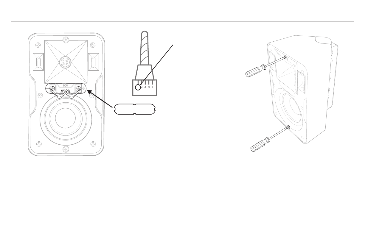
第 3 步
A. 使用螺丝刀或钻具组(按照最低转矩设定值,采用 2 号十字螺丝刀
刀头)将扬声器导线连接至扬声器端子。 确保极性连接正确。 通常
红色导线为正极 (+),黑色导线为负极 (-)。 只要同一系统中所有扬
声器的连接保持一致,至于哪一根导线连接至正极或负极端子,并没
什么关系。 确保两根导线均推入凹槽,取代端子盖。
如果使用随附支架
B. 一旦扬声器就位,将扬声器在支架臂上完全推回,直到与支架盖平
齐,然后将两个插入的螺钉完全旋入锁定位置。
最低钻矩设置实例
A.
B.
1 2 3 4 5

第 4 步
使用不同的安装支架(不使用随附支架)
声音测试: 使用扬声器播放音乐,确保连接紧密,极性正确。
第 5 步
一旦扬声器安装到位并通过测试,安装扬声器格栅(安装方法:将格栅压
入环绕扬声器前部的凹槽)。
* 扬声器格栅拆卸方法:使用随附格栅拆卸工具,将其插入上角,然后
轻轻拉出。 重复上述步骤,拉出其邻角,然后用一只手轻轻拉出格栅。
注: 设计的格栅紧贴在扬声器上,恰好能够与扬声器紧密贴合。 连续的
格栅拆卸/重新插入可能会导致格栅松动,从而产生振动或滑动。
所有 CP 系列扬声器均在背面底部设立了一个 1/4 英寸 20 牙螺纹插
孔,您可利用该插孔安装其他兼容支架。
3
2
4
5
1

扬声器上漆
扬声器与支架顶盖/底盖分开上漆。
1. 首先,使用中性溶剂或中性洗涤
剂/水清洁扬声器音箱和支架顶盖/
底盖。
2. 然后为扬声器前部(反射板)制作
一张油漆罩,制作方法:在一张无
孔厚纸上描出扬声器格栅的轮廓,
然后沿该轮廓将纸张裁切下来。
3. 将格栅纸罩放置在扬声器前部(
盖在反射板上),确保该纸罩还
遮住了格栅凹槽,然后用双面胶
带固定。 请勿将胶带贴在低音扬
声器上。 用该纸罩遮挡支架顶盖/
底盖,确保不要给支架臂和转动机
构上油漆。 遮挡格栅前部的公司
标志。
4. 使用塑料制品专用的喷漆,然后
喷涂扬声器音箱、支架盖和格栅前
部。 确保不要喷涂格栅孔。 在重
新组装扬声器之前,请晾干所有的
零部件。
1. 2.
3.
4.
溶剂油 中性洗涤剂
+ 水
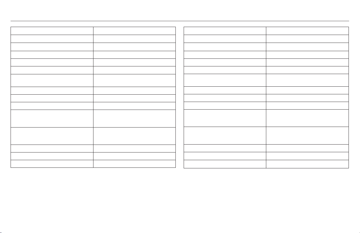
KLIPSCH CP-4 技术规格 KLIPSCH CP-6 技术规格
频率响应
1
80Hz-22kHz +3/-6 dB
功率容量
2
50 瓦 (峰值:200 瓦)
敏感度
3
91 dB @ 1 瓦/米
标称阻抗 8 欧姆
高音扬声器 0.75 英寸(1.9 厘米)铝制球顶高音扬声器
高频号角
90° x 90°Tractrix® 号角
低音扬声器 3.5 英寸(8.9 厘米)长冲程 IMG 低音
扬声器
分频频率 3.2kHz,12dB,八度音阶
音箱类型 通过双前推端口实现低音反射
重量 4.8 磅 (2.2 千克)
尺寸 高 x 宽 x 深:8.8 英寸(22.4 厘米) x
5.5 英寸(14.0 厘米) x 4.7 英寸(11.9
厘米)
尺寸(含壁挂支架)
高 x 宽 x 深:8.8 英寸(22.4 厘米) x
5.5 英寸(14.0 厘米) x 5.5 英寸(14.0
厘米)
表面涂层 白色/黑色音箱和格栅
适用的线规 16
制造年份 2014
1
3M,无回声
2
IEC 268-5 过滤粉红噪声,6dB 振幅因子
3
声压级 (1M 时),无回声,2.83V 输入
频率响应
1
70Hz-22kHz +3/-6 dB
功率容量
2
75 瓦 (峰值:300 瓦)
敏感度
3
94 dB @ 1 瓦/米
标称阻抗 8 欧姆
高音扬声器 0.75 英寸(1.9 厘米)铝制球顶高音扬声器
高频号角 90° x 90°Tractrix® 号角
低音扬声器 5.25 英寸(13.3 厘米)长冲程 IMG 低音
扬声器
分频频率 3kHz,12dB,八度音阶
音箱类型 通过双前推端口实现低音反射
重量 5.8 磅 (2.6 千克)
尺寸 高 x 宽 x 深:11.0 英寸(27.9 厘米) x
7.0 英寸(17.8 厘米) x 6.1 英寸(15.5
厘米)
尺寸(含壁挂支架)
高 x 宽 x 深:11.0 英寸(27.9 厘米) x
7.0 英寸(17.8 厘米) x 6.9 英寸(17.5
厘米)
表面涂层 白色/黑色音箱和格栅
适用的线规
16
制造年份
2014
1
3M,无回声
2
IEC 268-5 过滤粉红噪声,6dB 振幅因子
3
声压级 (1M 时),无回声,2.83V 输入

3502 WOODVIEW TRACE, INDIANAPOLIS, IN, USA
KLIPSCH.COM
©2013, Klipsch Group, Inc.
Klipsch Group, Inc. is a wholly-owned
subsidiary of Voxx International Corporation.