Loading ...
MODEL 112
Page 2
INSTALLATION
WARNING: To reduce the risk of fire, do not store or use gaso-
line or other flammable vapors and liquids in the vicinity of
the heater.
CAUTION: High temperature, risk of fire, keep electrical cords,
drapery, furnishings, and other combustibles at least 3 feet (0.9
m) from the front of the heater and away from the side and rear.
1. Mark the intended mounting location in the base plate under the
counter or kickspace, and remove required material to provide
for easy insertion and removal of the heater cabinet.
2. The unit will be secured in place with screws through the side
angle support brackets. Provide adequate material behind side
angle support for secure mounting.
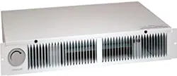
FIELD CONVERSION TO 120 V.A.C.
If a 120 V.A.C. circuit is to be used, make wiring changes as follows:
1. Disconnect white wire from heater element terminal “2” and
connect it to terminal “4.” The heater will now operate at 120
V.A.C., 750W, 6.3A.
2. For 120 V.A.C, 1500W, 12.5A operation, add the short red jumper
wire (provided) between terminals “1” and “2”.
3. Remove alarm light wire leads from terminals “1” and “3” of
the high temperature limit. Remove white wire lead from limit
terminal “1” and reconnect at limit terminal “3”. Secure wire leads
with wire tie so there is no interference with unit operation.
NOTE: Terminal numbers are marked on the side of the blower
housing, above the heater elements.
WIRING
Installation work and electrical wiring must be done by a qualified
person(s) in accordance with all applicable codes and standards,
including fire-rated construction codes and standards.
1. Run electrical power cable to installation location. Provide two
feet of slack to allow heater to be pulled out far enough to remove
top cover for cleaning or servicing.
NOTE: It is recommended that flexible conduit be used for field wir‑
ing to the unit to protect the wires from sharp objects or hazardous
environments.
NOTE: Be sure supply voltage meets the equipment requirement.
Refer to the rating plate, unit wiring diagram and specification table.
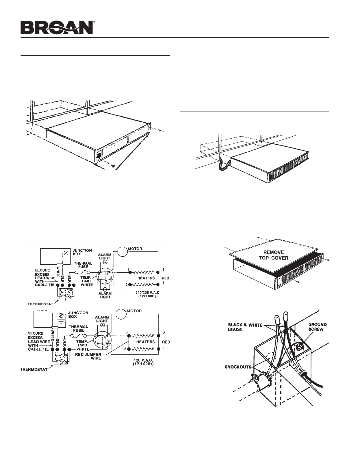
2. Remove top
cover for ac‑
cess to wiring
box at rear of
heater.
3. Remove one
of the two
knockouts
and connect
power cable
to heater us‑
ing appropriate connector. Allow at least six inches of wiring
inside of wiring box.
4. Connect black
to black, white
to white and
green (or bare
wire) to ground
screw, as
shown. Tuck
wires down in‑
side the wiring
box.
5. Replace top
cover.
WARNING: Do not
operate heater
without top cover
in place.
6. Slide heater
into place and
secure to mounting surface.
SIDE
ANGLE SUPPORT
BRACKETS
Loading ...
Loading ...
Loading ...