
AV SURROUND RECEIVER
AVR-2807
OPERATING INSTRUCTIONS
I
2 SAFETY PRECAUTIONS
CAUTION
RISK OF ELECTRIC SHOCK
DO NOT OPEN
CAUTION:
TO REDUCE THE RISK OF ELECTRIC SHOCK, DO NOT
REMOVE COVER (OR BACK). NO USER-SERVICEABLE
PARTS INSIDE. REFER SERVICING TO QUALIFIED SERVICE
PERSONNEL.
The lightning flash with arrowhead symbol, within an
equilateral triangle, is intended to alert the user to the
presence of uninsulated “dangerous voltage” within the
product’s enclosure that may be of sufficient magnitude
to constitute a risk of electric shock to persons.
The exclamation point within an equilateral triangle is
intended to alert the user to the presence of important
operating and maintenance (servicing) instructions in the
literature accompanying the appliance.
WARNING:
TO REDUCE THE RISK OF FIRE OR ELECTRIC SHOCK, DO
NOT EXPOSE THIS APPLIANCE TO RAIN OR MOISTURE.
1. Read Instructions – All the safety and operating instructions should be
read before the product is operated.
2. Retain Instructions – The safety and operating instructions should be
retained for future reference.
3. Heed Warnings – All warnings on the product and in the operating
instructions should be adhered to.
4. Follow Instructions – All operating and use instructions should be
followed.
5. Cleaning – Unplug this product from the wall outlet before cleaning.
Do not use liquid cleaners or aerosol cleaners.
6. Attachments – Do not use attachments not recommended by the
product manufacturer as they may cause hazards.
7. Water and Moisture – Do not use this product near water – for
example, near a bath tub, wash bowl, kitchen sink, or laundry tub; in
a wet basement; or near a swimming pool; and the like.
8. Accessories – Do not place this product on an unstable cart, stand,
tripod, bracket, or table. The product may fall, causing serious injury
to a child or adult, and serious damage to the product. Use only with
a cart, stand, tripod, bracket, or table recommended by the
manufacturer, or sold with the product. Any
mounting of the product should follow the
manufacturer’s instructions, and should use a
mounting accessory recommended by the
manufacturer.
9. A product and cart combination should be moved
with care. Quick stops, excessive force, and
uneven surfaces may cause the product and cart
combination to overturn.
10. Ventilation – Slots and openings in the cabinet are provided for
ventilation and to ensure reliable operation of the product and to
protect it from overheating, and these openings must not be blocked
or covered. The openings should never be blocked by placing the
product on a bed, sofa, rug, or other similar surface. This product
should not be placed in a built-in installation such as a bookcase or
rack unless proper ventilation is provided or the manufacturer’s
instructions have been adhered to.
11. Power Sources – This product should be operated only from the type
of power source indicated on the marking label. If you are not sure of
the type of power supply to your home, consult your product dealer
or local power company. For products intended to operate from
battery power, or other sources, refer to the operating instructions.
12. Grounding or Polarization – This product may be equipped with a
polarized alternating-current line plug (a plug having one blade wider
than the other). This plug will fit into the power outlet only one way.
This is a safety feature. If you are unable to insert the plug fully into
the outlet, try reversing the plug. If the plug should still fail to fit,
contact your electrician to replace your obsolete outlet. Do not defeat
the safety purpose of the polarized plug.
13. Power-Cord Protection – Power-supply cords should be routed so that
they are not likely to be walked on or pinched by items placed upon
or against them, paying particular attention to cords at plugs,
convenience receptacles, and the point where they exit from the
product.
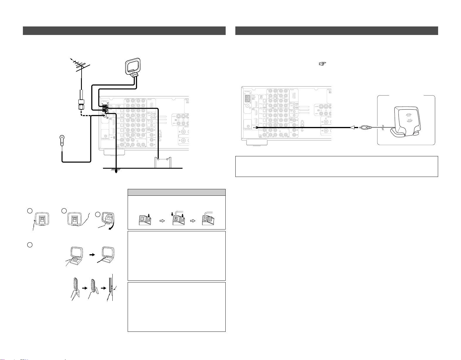
15. Outdoor Antenna Grounding – If an outside antenna or cable system
is connected to the product, be sure the antenna or cable system is
grounded so as to provide some protection against voltage surges
and built-up static charges. Article 810 of the National Electrical Code,
ANSI/NFPA 70, provides information with regard to proper grounding
of the mast and supporting structure, grounding of the lead-in wire to
an antenna discharge unit, size of grounding conductors, location of
antenna-discharge unit, connection to grounding electrodes, and
requirements for the grounding electrode. See Figure A.
16. Lightning – For added protection for this product during a lightning
storm, or when it is left unattended and unused for long periods of
time, unplug it from the wall outlet and disconnect the antenna or
cable system. This will prevent damage to the product due to
lightning and power-line surges.
17. Power Lines – An outside antenna system should not be located in
the vicinity of overhead power lines or other electric light or power
circuits, or where it can fall into such power lines or circuits. When
installing an outside antenna system, extreme care should be taken to
keep from touching such power lines or circuits as contact with them
might be fatal.
18. Overloading – Do not overload wall outlets, extension cords, or
integral convenience receptacles as this can result in a risk of fire or
electric shock.
19. Object and Liquid Entry – Never push objects of any kind into this
product through openings as they may touch dangerous voltage
points or short-out parts that could result in a fire or electric shock.
Never spill liquid of any kind on the product.
20. Servicing – Do not attempt to service this product yourself as opening
or removing covers may expose you to dangerous voltage or other
hazards. Refer all servicing to qualified service personnel.
21. Damage Requiring Service – Unplug this product from the wall outlet
and refer servicing to qualified service personnel under the following
conditions:
a) When the power-supply cord or plug is damaged,
b) If liquid has been spilled, or objects have fallen into the product,
c) If the product has been exposed to rain or water,
d) If the product does not operate normally by following the operating
instructions. Adjust only those controls that are covered by the
operating instructions as an improper adjustment of other controls
may result in damage and will often require extensive work by a
qualified technician to restore the product to its normal operation,
e) If the product has been dropped or damaged in any way, and
f) When the product exhibits a distinct change in performance – this
indicates a need for service.
22. Replacement Parts – When replacement parts are required, be sure
the service technician has used replacement parts specified by the
manufacturer or have the same characteristics as the original part.
Unauthorized substitutions may result in fire, electric shock, or other
hazards.
23. Safety Check – Upon completion of any service or repairs to this
product, ask the service technician to perform safety checks to
determine that the product is in proper operating condition.
24. Wall or Ceiling Mounting – The product should be mounted to a wall
or ceiling only as recommended by the manufacturer.
25. Heat – The product should be situated away from heat sources such
as radiators, heat registers, stoves, or other products (including
amplifiers) that produce heat.
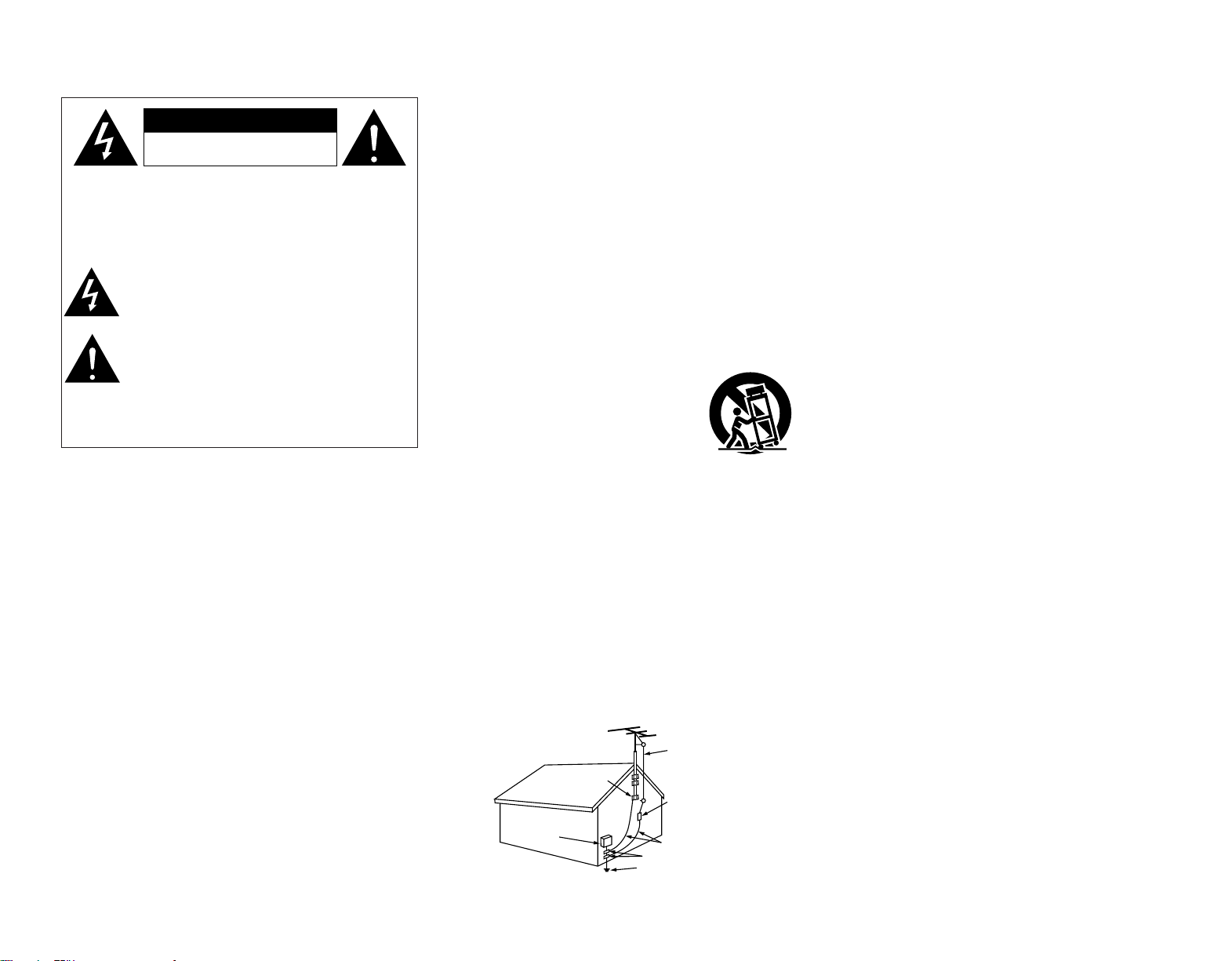
SAFETY INSTRUCTIONS
FIGURE A
EXAMPLE OF ANTENNA GROUNDING
AS PER NATIONAL
ELECTRICAL CODE
ANTENNA
LEAD IN
WIRE
GROUND
CLAMP
ELECTRIC
SERVICE
EQUIPMENT
ANTENNA
DISCHARGE UNIT
(NEC SECTION 810-20)
GROUNDING CONDUCTORS
(NEC SECTION 810-21)
GROUND CLAMPS
POWER SERVICE GROUNDING
ELECTRODE SYSTEM
(NEC ART 250, PART H)
NEC - NATIONAL ELECTRICAL CODE

II
2 NOTE ON USE
•Avoid high temperatures.
Allow for sufficient heat
dispersion when installed in a
rack.
•Handle the power cord carefully.
Hold the plug when unplugging
the cord.
• Keep the apparatus free from
moisture, water, and dust.
• Unplug the power cord when
not using the apparatus for long
periods of time.
* (For apparatuses with ventilation holes)
• Do not obstruct the ventilation
holes.
• Do not let foreign objects into
the apparatus.
• Do not let insecticides,
benzene, and thinner come in
contact with the apparatus.
• Never disassemble or modify
the apparatus in any way.
FCC INFORMATION (For US customers)
1. PRODUCT
This product complies with Part 15 of the FCC Rules. Operation is
subject to the following two conditions: (1) this product may not cause
harmful interference, and (2) this product must accept any interference
received, including interference that may cause undesired operation.
2. IMPORTANT NOTICE: DO NOT MODIFY THIS PRODUCT
This product, when installed as indicated in the instructions contained
in this manual, meets FCC requirements. Modification not expressly
approved by DENON may void your authority, granted by the FCC, to
use the product.
3. NOTE
This product has been tested and found to comply with the limits for a
Class B digital device, pursuant to Part 15 of the FCC Rules. These
limits are designed to provide reasonable protection against harmful
interference in a residential installation.
This product generates, uses and can radiate radio frequency energy
and, if not installed and used in accordance with the instructions, may
cause harmful interference to radio communications. However, there
is no guarantee that interference will not occur in a particular
installation. If this product does cause harmful interference to radio or
television reception, which can be determined by turning the product
OFF and ON, the user is encouraged to try to correct the interference
by one or more of the following measures:
• Reorient or relocate the receiving antenna.
• Increase the separation between the equipment and receiver.
• Connect the product into an outlet on a circuit different from that
to which the receiver is connected.
• Consult the local retailer authorized to distribute this type of
product or an experienced radio/TV technician for help.
This Class B apparatus complies with Canadian ICES-003.
Cet appareil numérique de la classe B est conforme à la norme NMB-
003 du Canada.

III
2
We greatly appreciate your purchase of the AVR-2807.
2
To be sure you take maximum advantage of all the features the AVR-2807 has to offer, read
these instructions carefully and use the set properly. Be sure to keep this manual for future
reference should any questions or problems arise.
“SERIAL NO.
PLEASE RECORD UNIT SERIAL NUMBER ATTACHED TO THE REAR OF THE CABINET FOR
FUTURE REFERENCE”
MEMO

1
Getting Started
Contents
Getting Started
Thank you for choosing the DENON AVR-2807 AV Surround Receiver. This remarkable component has been engineered to provide
superb surround sound listening with home theater sources such as DVD, as well as providing outstanding high fidelity reproduction
of your favorite music sources.
As this product is provided with an immense array of features, we recommend that before you begin hookup and operation that you
review the contents of this manual before proceeding.
Accessories··············································································3
Before using·············································································3
Cautions on installation ·························································3
About the remote control unit ··············································3
Inserting the batteries····························································3
Operating range of the remote control unit ························3
Part names and functions
Front panel··············································································4
Display ····················································································4
Rear panel···············································································5
Remote control unit································································5
Easy to setup flow··································································6
Speaker layout [Basic layout]················································6
Speaker connections ······························································7
Connecting a DVD player and monitor·································8
Auto Setup/Room Equalizer (Room EQ) Functions ············9
q Connecting a microphone··················································9
w Before performing the Auto Setup procedure·················10
e Perform the Auto Setup procedure ·································10
r Assigning power amplifiers ·············································10
t Switching the front speaker·············································10
y Preliminary measurements··············································11
u Speaker measurements···················································11
i Checking and storing the measurement results··············12
Error messages ····································································12
Cable indications···································································13
The video conversion function············································14
Relationship between the video input signal
and monitor output according to
the video convert settings··············································14, 15
Playing the input source ······················································23
Selecting the room equalizer mode ····································24
Turning the sound off temporarily (MUTING) ·······················24
Listening over headphones ··················································24
Switching the front speakers ··············································24
Checking the currently playing program source, etc.···········24
Switching the brightness of the display ·······························24
Basic Operation
Getting Started
Easy Setup Procedure
Connecting Other Sources
Night mode············································································38
User mode function······························································38
Combining the currently playing sound
with the desired image (VIDEO SELECT function)············38
Personal memory plus function ··········································38
Playing the iPod ····································································39
Listening to music ································································39
Viewing still pictures and videos (only for iPods
equipped with the slideshow / video function) ····················39
Disconnecting the iPod·························································39
Multi zone music entertainment system
Multi-zone playback using the ZONE2 output terminals······40
Multi-zone playback using the SPEAKER terminals ············40
Outputting a program source to amplifier, etc.,
in the ZONE2 room (ZONE2 SELECT mode) ·······················41
Remote control unit operations
during multi-source playback················································41
Recording (audio and/or video)···········································42
About the memory functions ··············································42
Initialization of the microprocessor (Reset) ······················42
The analog video to HDMI conversion function················15
Connecting equipment with HDMI terminals
[To convert analog video signals to HDMI signals]···········16
Connecting a TV tuner ·························································16
Connecting a DBS tuner·······················································16
Connecting the external inputs (EXT. IN) terminals··········17
Connecting a video camera or video game···························17
Connecting a CD player························································17
Connecting a turntable·························································17
Connecting a DVD recorder·················································18
Connecting a VCR·································································18
Connecting a tape deck························································18
Connecting a CD recorder or MD recorder·························19
Connecting equipment with HDMI terminals····················19
Connecting the antenna terminals······································20
Connecting the XM terminal ···············································20
Connecting the iPod ····························································21
Connecting the RS-232C terminal·······································21
Connecting the TRIGGER OUT jacks ··································21
Connecting the MULTI ZONE terminals
ZONE2 out connections ·······················································21
ZONE2 speaker out connections··········································22
Connecting the PRE OUT terminals····································22
Connecting the power supply cord·····································22
Using the surround modes
Types of surround modes and their features ·······················25
Selecting the play mode
(PURE DIRECT / DIRECT / STEREO)····································25
Selecting the Dolby Digital and DTS Surround mode
(only with digital input) ···················································26, 27
Selecting the Dolby Pro Logic
II
x (Pro Logic
II
) mode ·········27
Selecting the DTS NEO:6 mode···········································28
Checking the input signals ···················································28
Surround modes and parameters ································29 ~ 31
Using the DENON original surround modes
Types of surround modes and their features ·······················32
Selecting the DSP surround simulation································33
Setting the tone control························································34
Adjusting the speaker volume··············································34
Using the fader function·······················································35
Listening to the radio
Auto tuning ···········································································35
Manual tuning·······································································35
Preset memory·····································································35
Checking the preset stations················································36
Recalling preset stations ······················································36
XM Satellite Radio································································36
Checking the XM signal strength and Radio ID ···················37
Channel selection ·································································37
Category search····································································37
Advanced Operation

Getting Started Getting Started
2
System setup items and default values·····················43 ~ 45
Navigating through the System Setup Menu····················46
About the display··································································46
Audio Input Setup
Setting the Digital In Assignment·········································47
Setting the EXT. IN Subwoofer Level ··································47
Setting the iPod Assignment ···············································47
Setting the Input Function Level ··········································48
Setting the Function Rename···············································48
Setting the Tuner Presets···············································48, 49
Video Setup
Setting the HDMI In Assignment···································49, 50
Setting the Component In Assignment································50
Setting the Video Convert ····················································50
Setting the HDMI Out Setup················································51
Setting the Audio Delay························································51
Setting the On Screen Display (OSD) ··································52
Advanced Playback
Setting the 2ch Direct/Stereo···············································52
Setting the Dolby Digital Downmix Option Setup················53
Setting the Auto Surround Mode ·········································53
Setting the Manual Equalizer Setup ······························53, 54
Option Setup
Setting the Power Amplifier Assignment·····························54
Setting the Volume Control ··················································55
Setting the Trigger Out·························································55
Setting the Setup Lock·························································56
Speaker Setup
Setting the Speaker Configuration ·································56, 57
Setting the Subwoofer Setup···············································57
Setting the Distance·······················································57, 58
Setting the Channel Level ··············································58, 59
Setting the Crossover Frequency·········································59
Others Setup
Setting the Room Equalizer Setup ·······································60
Setting the Direct Mode Setup ············································60
Setting the MIC Input Select················································61
Check the parameter····························································61
Troubleshooting······························································
69, 70
Additional Information·················································
66 ~ 68
Specifications ········································································
70
List of preset codes ····································End of this manual
Operating DENON audio components································62
Setting the preset memory function ··································62
Operating a component stored in the preset memory·····63
Setting the learning function···············································64
Using the system call function············································64
Registering············································································64
Operating··············································································64
Setting the punch through function···································65
Resetting the remote control unit
Resetting the learning function ············································65
Resetting the punch through setting ··································65
Advanced Setup – Part 2
Advanced Setup – Part 1 Operating the remote control unit

3
Getting Started Getting Started
Before using
Pay attention to the following before using this unit:
• Moving the unit
To prevent short-circuits or damaged wires in the connection
cables, always unplug the power supply cord and disconnect
the connection cables between all other audio components
when moving the unit.
• Before turning the power switch on
Check once again that all connections are correct and that there
are not problems with the connection cables. Always set the
power switch to the standby position before connecting and
disconnecting connection cables.
• Store these instructions in a safe place.
After reading, store this instructions along with the warranty
card in a safe place.
• Whenever the power switch is in the STANDBY state, the
unit is still connected to AC line voltage.
Please be sure to turn off the power switch or unplug the
cord when you leave home for, say, a vacation.
• Note that the illustrations in these instructions may differ
from the actual unit for explanation purposes.
About the remote control unit
In addition to controlling the AVR-2807, the attached remote
control unit (RC-1030) can also be used to control the following
products:
q DENON component products
w Component products other than DENON:
• Set using the preset memory function ( page 62, 63).
• Set using the learning function ( page 64).
Cautions on installation
Wall
Note
Note:
For heat dispersal, do not install this unit in a confined space
such as a bookcase or similar enclosure.
Inserting the batteries
q Remove the remote control
unit’s rear cover.
w Set 3 R6P/AA batteries in
the battery compartment in
the indicated direction.
e Put the rear cover back on.
Notes on batteries:
• Replace the batteries with new ones if the set does not
operate even when the remote control unit is operated
nearby the unit. (The attached batteries are only for verifying
operation.)
•When inserting the batteries, be sure to do so in the proper
direction, following the “<” and “>” marks in the battery
compartment.
•To prevent damage or leakage of battery fluid:
• Do not use a new battery together with an old one.
• Do not use two different types of batteries.
• Do not short-circuit, disassemble, heat or dispose of
batteries in flames.
• Remove the batteries from the remote control unit when
you do not plan to use it for an extended period of time.
• If the battery fluid should leak, carefully wipe the fluid off the
inside of the battery compartment and insert new batteries.
•When replacing the batteries, have the new batteries ready
and insert them as quickly as possible.
Accessories
Check that the following parts are attached in addition to the
main unit:
q Operating instructions ......................................................1
w Warranty (for North America model only) .............................1
e Service station list.............................................................1
r Power supply cord (Approx.7-31/64 ft / 1.9 m).................1
t Remote control unit (RC-1030) .........................................1
y R6P/AA batteries ..............................................................3
u AM loop antenna ..............................................................1
i FM indoor antenna............................................................1
o Setup microphone (DM-S205) (Approx. 23-5/8 ft / 6 m)...1
rty
uio
Operating range of the remote control unit
30°
30°
Approx. 23 feet/7 m
• Point the remote control unit at the remote sensor when
operating it.
• The remote control unit can be used from a distance of
approximately 23 feet/7 meters, at a horizontal angle of up to
30° with respect to the sensor.
NOTE:
• It may be difficult to operate the remote control unit if the
remote sensor is exposed to direct sunlight or strong
artificial light.
4
Getting Started Getting Started
Display
q
Input signal indicator
w
Input signal channel indicator
• The audio channel(s) included in the input
signal light(s).
•This lights when the digital signal is inputted.
e
Information display
r
Output signal channel indicator
The audio channels that can be output light.
t
Speaker indicator
This lights corresponding to the settings of
the surround speakers of the various
surround modes.
y
Master volume indicator
This displays the volume level.
The Setup item number is displayed in
System Setup.
u
MULTI (zone) indicator
ZONE2 mode is selected in ZONE2/REC
SELECT.
i
REC indicator
REC OUT mode is selected in ZONE2/REC
SELECT.
o
AL24 indicator
This lights when the following mode is
selected while inputting digital (PCM)
signals.
PURE DIRECT / DIRECT / STEREO /
MULTI CH PURE DIRECT /
MULTI CH DIRECT / MULTI CH IN
!0
Input mode indicator
!1
AUTO indicator
This lights when the broadcast station is
selected in the AUTO tuning mode.
!2
TUNED indicator
This lights when an FM/AM broadcast has
been received.
!3
STEREO indicator
This lights when an FM stereo broadcast has
been received.
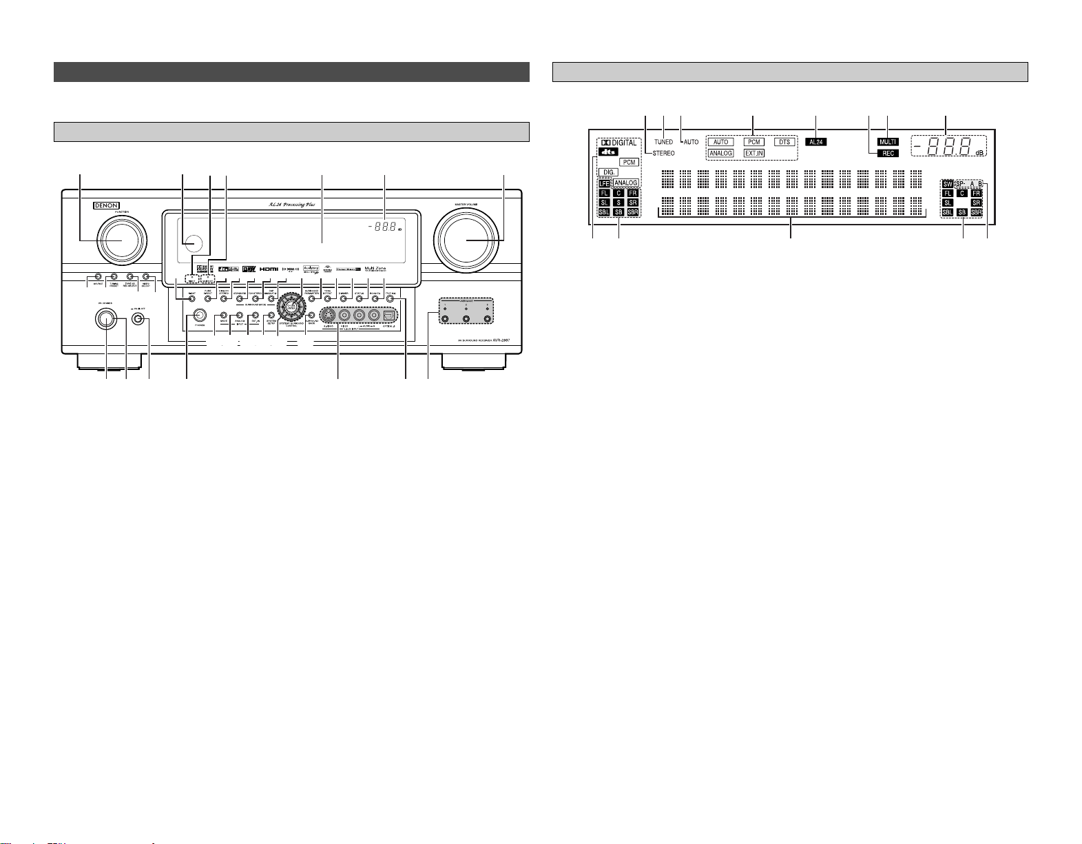
Part names and functions
Front panel
For details on the functions of these parts, refer to the pages given in parentheses ( ).
q
Power ON/STANDBY button··············(10)
w
Power indicator····································(10)
e
Power switch········································(10)
r
Headphones jack (PHONES) ···············(25)
t
V.AUX INPUT terminals ······················(17)
y
SETUP MIC jack ·····································(9)
u
USER MODE buttons···························(38)
i
MASTER VOLUME control knob········(23)
o
Master volume indicator
!0
Display
!1
MultEQ XT indicator····························(24)
!2
NIGHT indicator ···································(38)
!3
Remote control sensor··························(3)
!4
FUNCTION knob···································(23)
!5
SOURCE button ···································(23)
!6
TUNING PRESET button ·····················(36)
!7
ZONE2/REC SELECT button·········(41, 42)
!8
VIDEO SELECT button·························(38)
!9 NIGHT button·······································(38)
@0 PURE DIRECT button···························(25)
@1
DIRECT/STEREO button······················(25)
@2
STANDARD button ······························(26)
@3
7CH STEREO button····························(33)
@4
DSP SIMULATION button ···················(33)
@5
CH SELECT/ENTER button ···········(10, 34)
@6
SURROUND PARAMETER button ······(26)
@7
TONE DEFEAT button··························(34)
@8
DIMMER button ···································(24)
@9
STATUS button ····································(24)
#0
ROOM EQ button·································(24)
#1
SURROUND BACK button ··················(26)
#2
Cursor (
DD
,
HH
,
FF
,
GG
) buttons···············(10)
#3
SYSTEM SETUP button ······················(10)
#4
EXT. IN button······································(23)
#5
ANALOG button···································(23)
#6
INPUT MODE button ···························(23)
@0@0
@1@1
@2@2
@3@3
@4@4!9!9 @5@5
@6@6@7@7@8@8@9@9#0#0
!4 !0 oi!3 !2
@0
!1
@1
@2
@3
@4
!9 @5
@6@7@8@9#0
q w e r
t
u
#6
#5
#4
#3 #1
#2
y
!5
!8!7
!6
yuio!0!1!2!3
e
r t
q
w

5
Getting Started Getting Started
Remote control unit
Remote control signal
transmitter···················(3)
Power buttons
····································(10)
Tuner system/System
buttons·······················(35)
Surround buttons
····································(25)
NIGHT button
····································(38)
ROOM EQ button
····································(24)
MUTING button
····································(24)
Master volume control
buttons·······················(23)
CH SELECT/ENTER
button···················(10, 34)
SURROUND PARAMETER
button·························(26)
SEARCH/RETURN
button·························(63)
ZONE1 (MAIN) buttons
····································(41)
Rear panel
q
DIGITAL terminals
(Optical/Coaxial) ·······································(8)
w
AUDIO terminals····································(8)
e
PRE OUT terminals······························(22)
r
SIGNAL GND terminal·························(17)
t
TRIGGER OUT jacks·····························(21)
y
Speaker terminals··································(7)
u
AC outlets·············································(22)
i
AC inlet ·················································(22)
o
COMPONENT VIDEO terminals············(8)
!0
VIDEO/S-VIDEO terminals····················(8)
!1
REMOTE CONTROL jacks····················(21)
!2
RS-232C terminal·································(21)
!3
EXT. IN terminals·································(17)
!4
HDMI MONITOR terminals··················(19)
!5
ANTENNA terminals····························(20)
!6
DOCK CONTROL jack ··························(21)
!7
XM terminal··········································(20)
USER MODE buttons
····································(38)
Function/Number
buttons·················(23, 63)
ZONE2 buttons
····································(41)
LEARNED/TX Indicator
····································(62)
MODE SELECT button
····································(62)
System buttons
····································(63)
SYSTEM SETUP/SETUP
button·························(10)
Cursor buttons
····································(10)
ON SCREEN/DISPLAY
button···················(24, 63)
TEST TONE button
····································(56)
Mode selector buttons
····································(62)
USE/LEARN button
····································(64)
SYSTEM CALL buttons
····································(64)
FRONT SPEAKER button
····································(24)
INPUT MODE button
····································(23)
To operate the AVR-2807, use the mode selector buttons to select “TAPE” “CDR/MD” or “CD”,
mode.
q!7 ew r t y u!6
io!0!2!3 !1!4!5
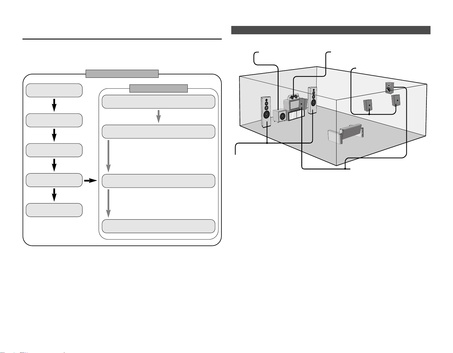
6
Easy Setup Procedure
Speaker layout [Basic layout]
Example of basic layout with 8 speakers and a monitor.
Subwoofer Center speaker
Surround speaker
Surround back speaker
Front speaker
Set these at the sides of the
monitor or screen with their front
surfaces as flush with the front
of the screen as possible.
• This section contains the basic steps necessary to configure the AVR-2807 according to your
listening room environment and the source equipment and loudspeakers you are using.
•To set the sound field manually, see pages 56 ~59.
Easy to setup flow
Easy Setup Procedure
Placing the speakers.
Connecting the
speakers.
Connecting a monitor
and a DVD player.
Starting the Auto
Setup.
Playing a DVD with
surround sound.
Auto setup flow
1) Speaker Configuration
2) Distance
3) Channel Level
4) Crossover Frequency
5) Room Equalizer
1) Measuring the background noise (noise in the
room)
2) Determining whether or not speakers are
connected
3) Checking the polarities of the speakers
Connecting a microphone.
Preliminary measurement.
Measurement of the speakers
in the listening position.
Speaker measurement check
and storage in memory.
><>< ><><
><
><><><><
IN
(
L
) (
R
) (
L
) (
R
)
(
L
) (
R
) (
L
) (
R
)
ImpedanceSpeaker
7
Easy Setup Procedure Easy Setup Procedure
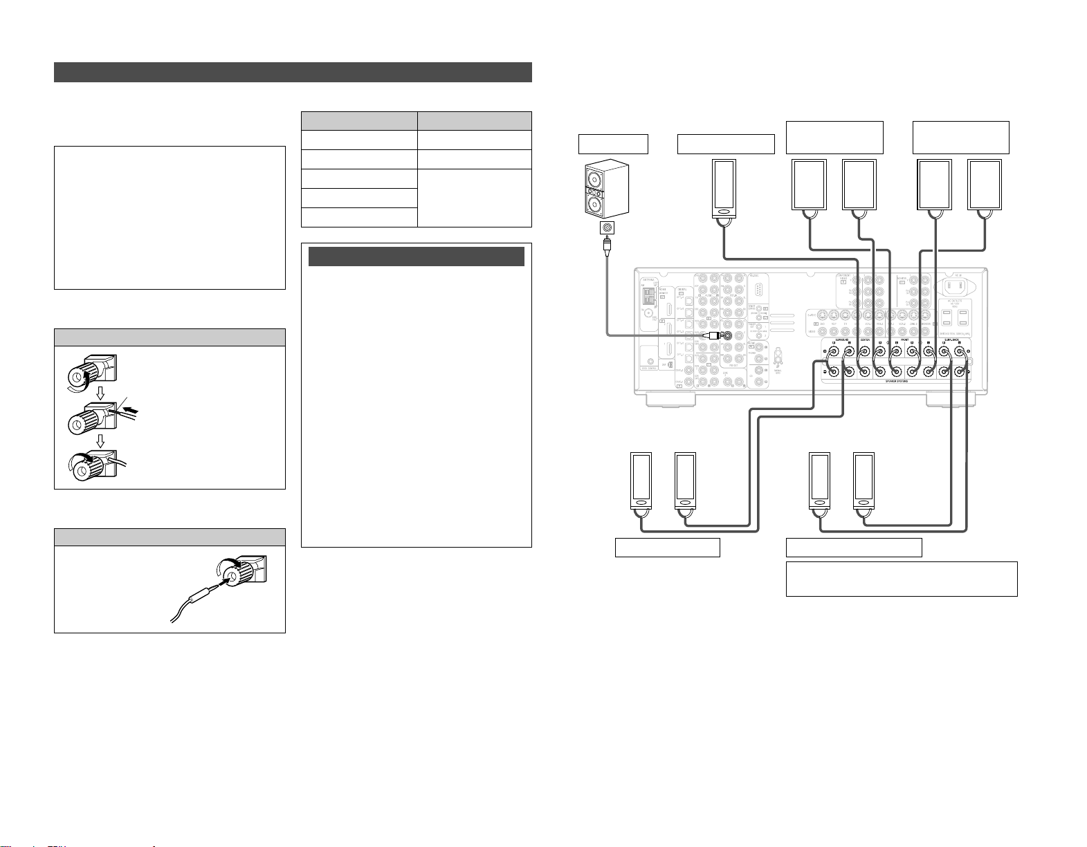
Connecting the speaker cables
2 Connections
•With the AVR-2807, up to 10 speakers can be connected for surround playback.
• When making connections, also refer to the operating instructions of the other components.
When using only one surround back
speaker, connect it to the left channel.
Connection
terminal for
subwoofer
with built-in
amplifier.
Speaker connections
Connect the speaker terminals with the
speakers making sure that like polarities are
matched (
<
with
<
,
>
with
>
).
2 Speaker impedance
Note on speaker impedance
When using speakers with an impedance
below the designated value (for example 4
Ω/ohms), playing for long periods of time
with the volume high could cause the
temperature to rise, activating the protection
circuit.
When the protection circuit is activated, the
output to the speakers is cut off and the
power indicator blinks. If this happens,
unplug the power cord, wait for the set to
cool off and improve ventilation around the
unit. Also check the wiring of the input
cables and the speaker cables. After doing
this, plug the power cord back in and turn
the unit’s power back on.
If the protection circuit is activated again
even though there are no problems with the
wiring or the ventilation around the unit,
switch off the power and contact a DENON
service center.
NOTE:
When making connections, take care that
none of the individual conductors of the
speaker cable come in contact with
adjacent terminals, with other speaker
cable conductors, or with the rear panel
and screws.
NEVER touch the speaker terminals
when the power is on. Doing so could
result in electric shocks.
1. Loosen by turning
counterclockwise.
Either tightly twist or terminate the
core wires.
2. Insert the cable.
3. Tighten by turning
clockwise.
Front speaker
(B)
Surround speaker
Front speaker
(A)
Subwoofer
Surround back speaker
Center speaker
6 ~ 16 Ω/ohms
Center
Surround
Surround back
6 ~ 16 Ω/ohmsFront A, B
8 ~ 16 Ω/ohmsFront A+B
Connecting banana plugs
Turn clockwise to tighten,
then insert the banana plug.
8
Easy Setup Procedure Easy Setup Procedure
• For best picture quality (especially with progressive DVD and other high definition sources),
choose the component video or HDMI connection to your monitor. S-Video and composite video
outputs are also provided if your monitor does not have component video inputs.
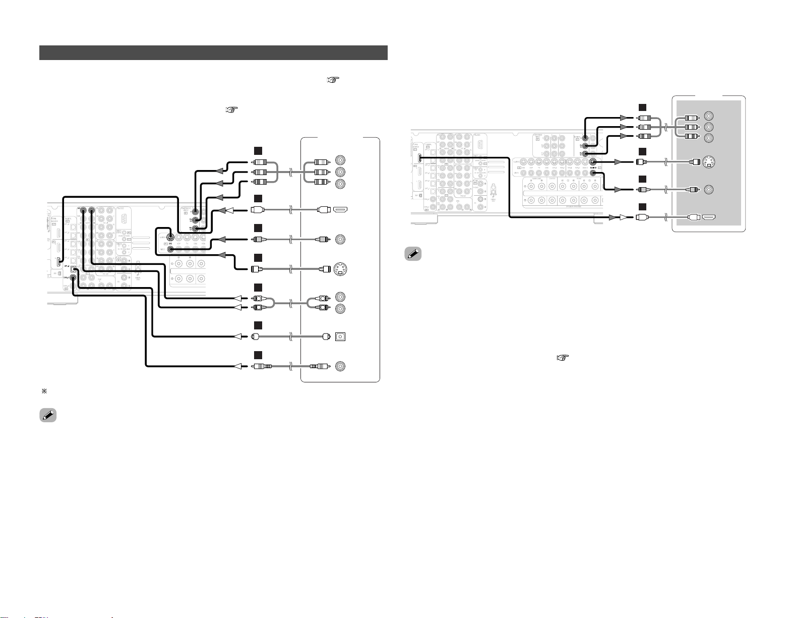
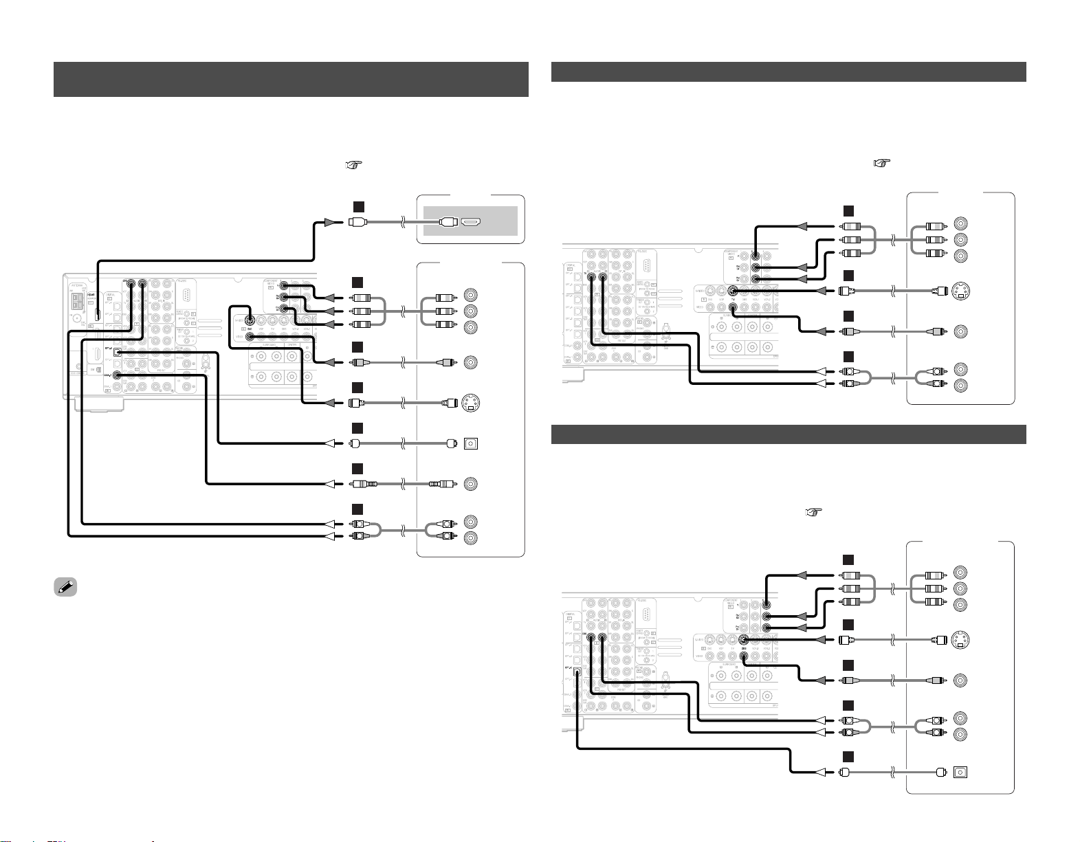
Connecting a DVD player and monitor
•To connect the video output from the DVD player to the AVR-2807, you only need to choose one
connection type. For more information about the video up conversion function ( page 14, 15).
•To connect the digital audio output from the DVD player, you can choose from either the coaxial
or optical connections. If you choose to use the optical connection, it needs to be assigned. For
more information about Digital Input Assignment ( page 47).
Audio signal flow is shown with white arrows, video signal flow is shown with gray arrows.
• The AVR-2807 is equipped with another set of input terminals for a non-DVD video disc player
(such as laser disc, VCD/SVCD, or future high definition disc player). The above connection
guidelines for DVD also apply to the VDP input.
• The AVR-2807 is equipped with HDMI terminals, so it can be connected to a DVD player or
monitor using an HDMI cable.
• The component video input and/or output terminals may be labelled differently on some monitors
or video components. Check the owner’s manuals for other components for further information.
• The COMPONENT MONITOR OUT-1 and the COMPONENT MONITOR OUT-2 can be used
simultaneously.
• Audio signals are only output from the HDMI monitor out terminal when audio signals are input
to the HDMI input terminal.
• When connecting the AVR-2807 and DVD player using an HDMI cable, also connect the AVR-
2807 and monitor using an HDMI cable ( page 19).
DVD player
S VIDEO
OUT
COAXIAL
OUT
R
L
AUDIO OUT
VIDEO
OUT
COMPONENT VIDEO OUT
Y
P
B
PR
OPTICAL
OUT
HDMI
OUT
R
L
R
L
F
H
G
A
C
D
I
Monitor
S VIDEO
IN
VIDEO
IN
COMPONENT VIDEO IN
Y
P
B
PR
HDMI
IN
F
H
G
I
Easy Setup Procedure Easy Setup Procedure
9
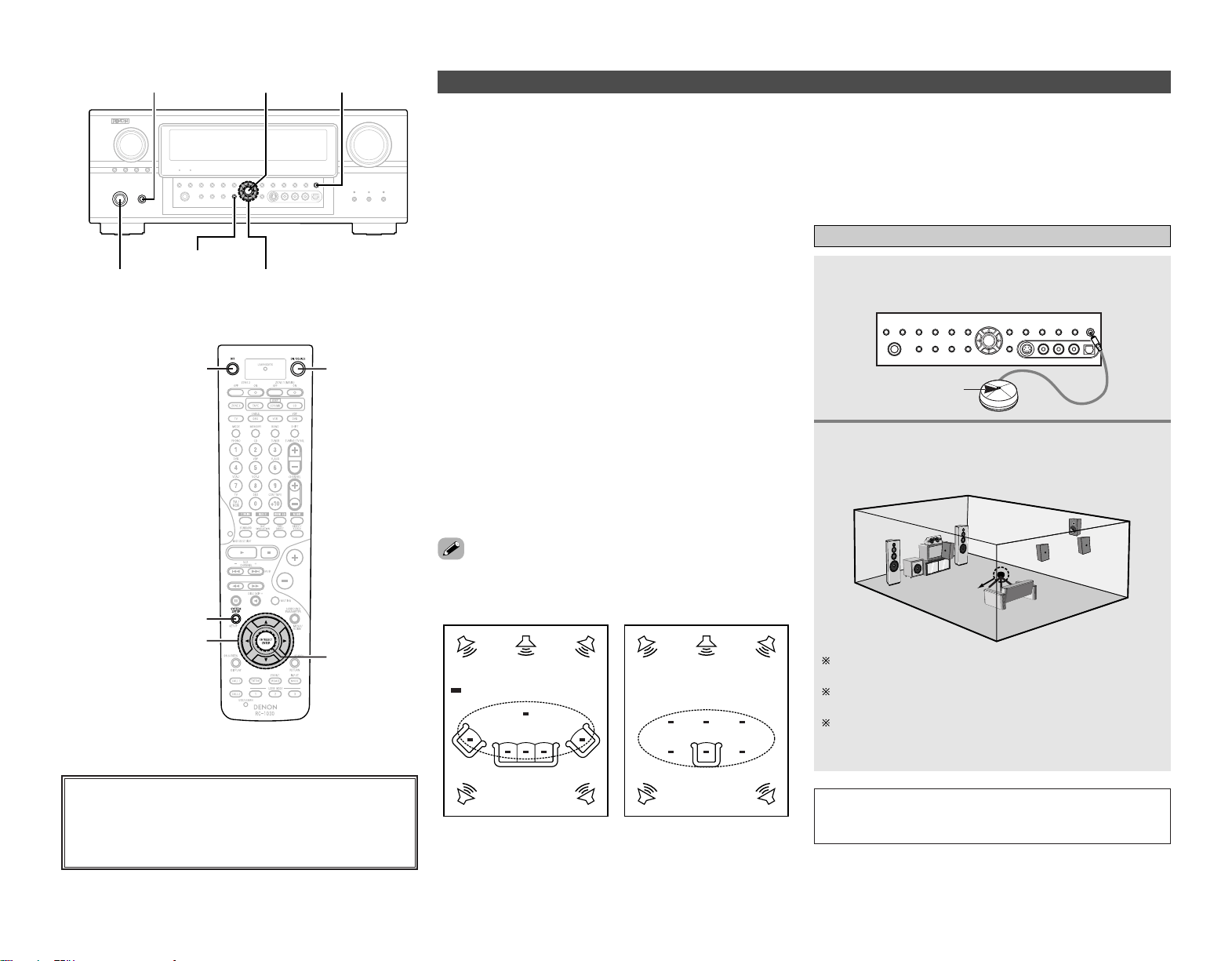
Auto Setup/Room Equalizer (Room EQ) Functions
• The AVR-2807’s auto setup and room equalizer functions use
the attached microphone to measure the acoustic properties in
the room and automatically make the optimum settings.
• The optimum listening environment at all listening positions in
the home theater is achieved so multiple listeners can enjoy
listening at the same time.
As shown in Example q, as you make the measurements,
move the microphone successively to the different positions in
which the members of the family sit within the listening area
surrounded by the speakers. For best results, make the
measurements at 6 locations.
Even if the home theater is only used by a small number of
people, as in Example w, more effective equalization can be
achieved by taking the measurements in the area around the
listening position.
• When the auto setup procedure is performed, one of the
following 3 correction curves can be selected for the room
equalizer function.
Audyssey:
The frequency response of all the speakers is adjusted to
achieve the optimum environment for the room’s acoustics.
Front:
This adjusts the characteristics of each speaker to the
characteristics of the front speakers.
Flat:
This the frequency response of all speakers flat. This mode is
optimum for playing multi-channel signal music.
2 About the main listening position (*M)
The “main listening position” refers to either the center of the
listening position or the position in which the user sits when
using the system alone. The distance to the speakers is
measured from this position.
•To make the sound field settings manually, see pages 56 ~ 59.
*
M
Example: q
*
M
Example: w
ENTER
D
H
F
G
SYSTEM SETUP
[OFF]
[ON]
<ON/STANDBY>
SYSTEM SETUP
D
H
F
G
<POWER> ENTER <SETUP MIC>
( : Measurement positions)
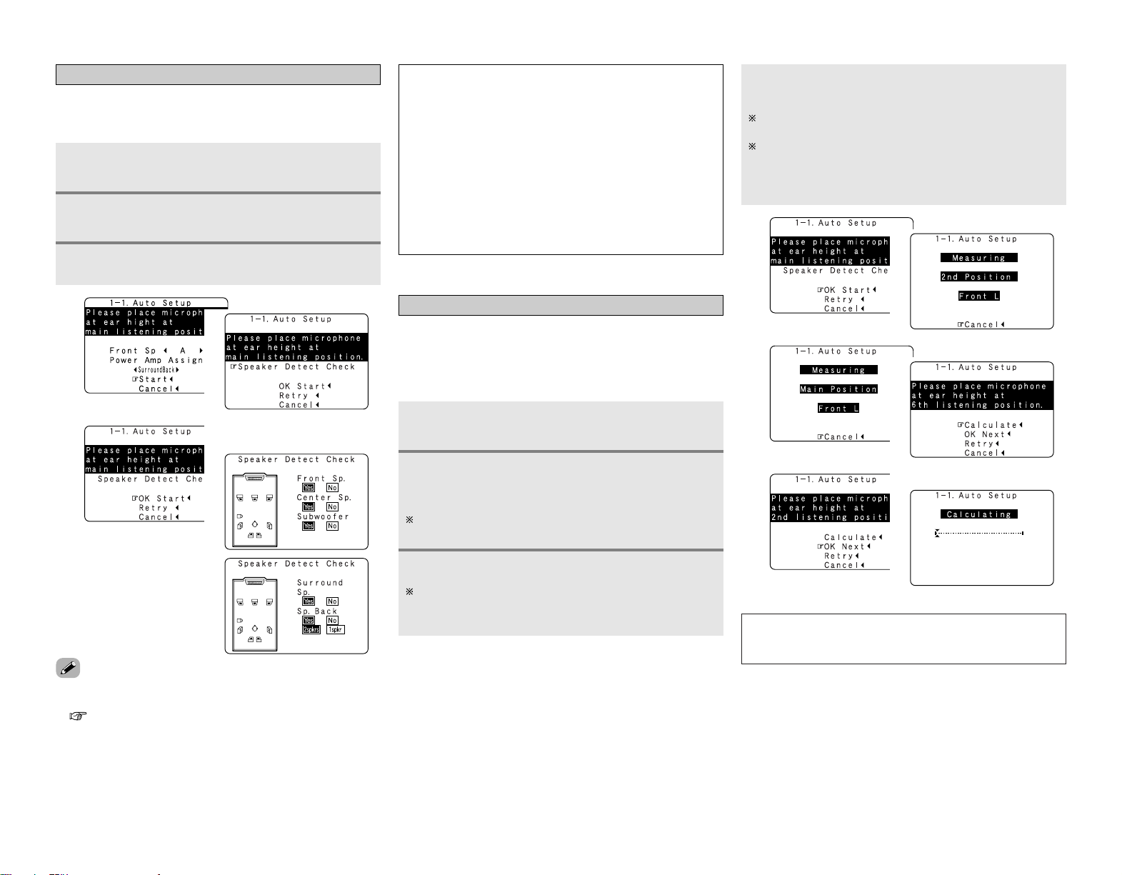
q Connecting a microphone
Connect the attached setup microphone to
<
SETUP MIC
>
.
Mount the setup microphone on a camera tripod,
etc., and set with the receptor pointing towards
the ceiling.
Microphone
NOTE:
• Once the settings are completed, disconnect the setup
microphone.
Place the setup microphone’s sound receptor at the height
of the ears in the listening position.
Be sure that at the beginning, the measurement is started
with the microphone set up at the main listening position.
It is not possible to measure properly if there are any
obstacles between the speakers and microphone. Check
that there are no obstacles.
About the button names in this explanation
<>: Buttons on the main unit
[]: Buttons on the remote control unit
Button name only :
Buttons on the main unit and remote control unit
Sound receptor
1
2
10
Easy Setup Procedure Easy Setup Procedure
Press
<
ON/STANDBY
>
or [ON].
• The power indicator blinks green and the power turns on.
Press
<
POWER
>
.
£ OFF:
The power turns off and the indicator is off.
¢ ON:
The power indicator lights red.
Turn on your subwoofer.
Set the volume to halfway and set the crossover frequency
to the maximum or Low pass filter off if your subwoofer can
adjust the output volume and the crossover frequency.
Some subwoofers have a standby mode. Be sure to turn
this function off before performing the Auto Setup
procedure.
Turn on your monitor.
w Before performing the Auto Setup
procedure
1
2
3
4
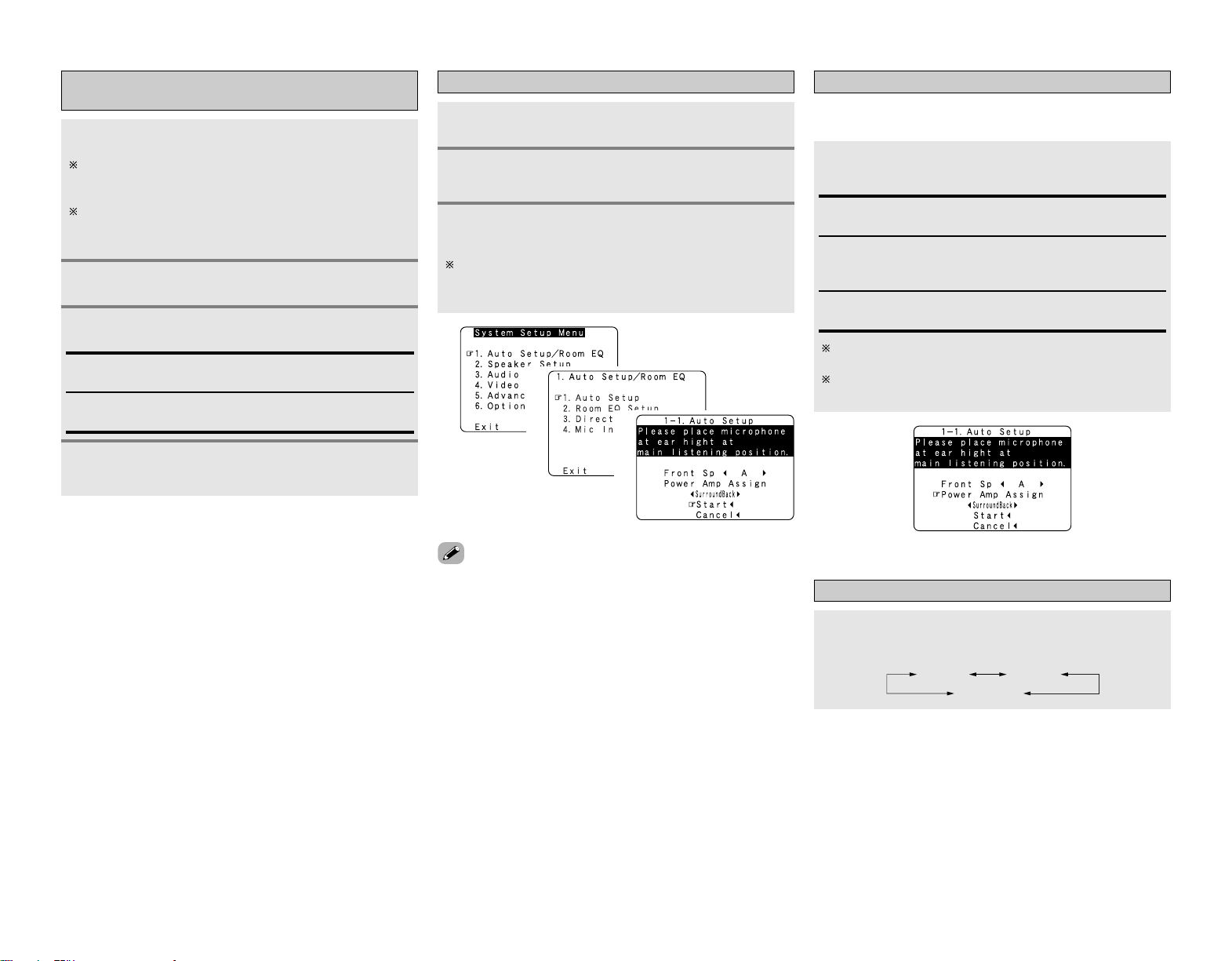
e Perform the Auto Setup procedure
Press
DD HH
to select “Auto Setup / Room EQ”,
then press ENTER.
Press SYSTEM SETUP.
Press
DD HH
to select “Auto Setup”, then press
ENTER.
The message “Connect Microphone” is displayed if no
microphone is connected. If so, connect the auto setup
microphone.
1
2
3
• “System Setup Menu” is not displayed when using
headphones.
1
2
3
r Assigning power amplifiers
Press
DD HH
to select “Power Amp Assign”, then press
FF GG
to set.
The surround back output can be assigned to the “Front” or
“ZONE2” output.
Front A, Front B:
Assign to use the “Front A” (or “Front B”) speakers with bi-
amp connections.
Surround Back:
Assign to use as surround back speaker.
When assigned to “Front”, skip the surround back channel
measurement.
During the auto setup procedure, test tones are not output
to “ZONE2”.
ZONE2:
Assign to use as “ZONE2” speakers.
t Switching the front speaker
Press
DD HH
to select “Front Sp”, then press
FF GG
to
select the speaker.
Front A
Front A+B
Front B
(After completion of
measurement for first point)
(After measurement
completed)
11
Easy Setup Procedure Easy Setup Procedure
y Preliminary measurements
This procedure is used to automatically determine the
background noise, whether or not speakers are connected, and
the polarities of the connected speakers.
Press
DD HH
to select “Start”, then press
FF
.
•The preliminary measurements start.
1
1
• If the results are not as expected or if an error message is
displayed, select “Retry” and perform the measurements again
( page 12).
• If the results of remeasurement are still not as expected or if an
error message is displayed, turn off the power switch and
check the speaker connections. Then start the measurements
again from the beginning.
Press ENTER again.
Cautions during measurements:
• Loud test tones are output during the measurements. Be
careful for example when small children are nearby.
•Proper measurements may not be possible if there are
obstacles between the speaker and the setup microphone.
•During the measurements, do not stand between or near
the speakers and setup microphone.
•To avoid influencing the measurements, turn off the power
of air-conditioners or any other equipment producing sound
in the room. Perform the measurements with the room as
quiet as possible.
•Measurement is cancelled when VOLUME is operated while
the Auto Setup is performed.
3
u Speaker measurements
Press
DD HH
to select “OK Start”, then press
FF
.
•Measurements for the first point start.
With these measurements, the “Speaker Configuration”,
“Distance”, “Channel Level”, “Crossover Frequency” and
“Room EQ” settings are analyzed automatically. The main
listening position is measured first, so leave the microphone
where it is.
1
Perform step 2 repeatedly.
Measurements can be ended when there are 6 or less
measurement locations; however, to obtain better results,
measurements at 6 locations is recommended.
Press
DD HH
to select “Calculate”, then press
FF
.
• The speaker is analyzed.
Once the calculations are completed, a screen for
confirming the results of the measurements appears.
The amount of time required for the analysis depends on the
number of speakers and the number of measuring points.
The greater the number of speakers and measuring points,
the longer the time required.
Move the microphone to the second point and
press
FF
.
•Measurements for the second point start.
Once the measurements are finished, the results of the
measurements for the second point are displayed.
2
3
4
1
hh
NOTE:
• Do not change the speaker connections or subwoofer
volume after making the measurements.
4
hh
Press
DD HH
to select “Speaker Detect Check”, then
press ENTER.
2
2
hh
hh
(Press ENTER.)
(Screen after initial measurement)
2
hh
Measures
Cause
Example
12
Easy Setup Procedure Easy Setup Procedure
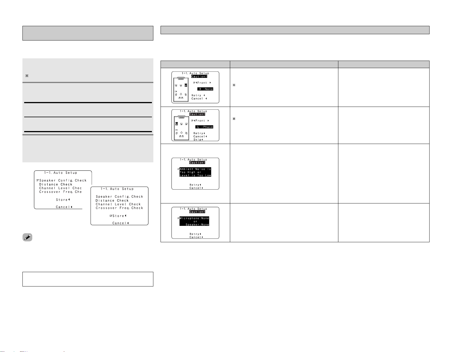
i Checking and storing the measurement
results
Press
DD HH
to select the item, then press ENTER.
Press ENTER to switch to the second screen.
The measurement results displayed at “u Speaker measurements”
can be checked and stored in the memory.
1
Store:
All the settings are stored in the memory.
After checking, press ENTER, then press
DD HH
to
set.
When “Store” is selected:
Press
FF
.
•After the data is stored, the “Auto Setup / Room EQ”
screen appears automatically.
Cancel:
Cancel the auto setup settings.
• When measurements have been made using the measurement
microphone, speakers with a built-in filter such as subwoofers
might be set with a value that differs from the physical distance
because of the internal electrical delay.
NOTE:
• Do not turn off the power while the data is being stored.
2
3
1
2
q The speakers required for producing suitable
reproduction have not been detected.
If multiple errors occur, press
FF GG
to check the
contents.
• Check that the pertinent speakers are properly
connected.
w The speaker polarity is connected in reverse.
If multiple errors occur, press
FF GG
to check the
contents.
• Check the polarity of the pertinent speakers.
• For some speakers, the screen below may be
displayed even though the speakers are
properly connected.
If so, select “Skip
0
”.
e There is too much ambient noise in the room and the
measurements cannot be made accurately.
r The sound level that is output from the speakers and/or
subwoofer is too low.
• Either turn off the power of the device that
generated the noise during the measurements
or move the device away.
•Try again at a time when it is quieter.
• Check the placement and orientation of the
loudspeakers.
• Adjust the subwoofer’s output level.
t The measurement microphone is not connected, or all
of speakers have not been detected.
• Connect the attached setup microphone to
<
SETUP MIC
>
.
• Check the speaker connection.
Error messages
An error message is displayed if the measurements could not be completed automatically due to the speaker layout, the measuring
environment, etc. Please check the following matters, reset the pertinent items, and measure again.
Be sure to turn off the AVR-2807’s power before checking the speaker connections.
13
Connecting Other Sources
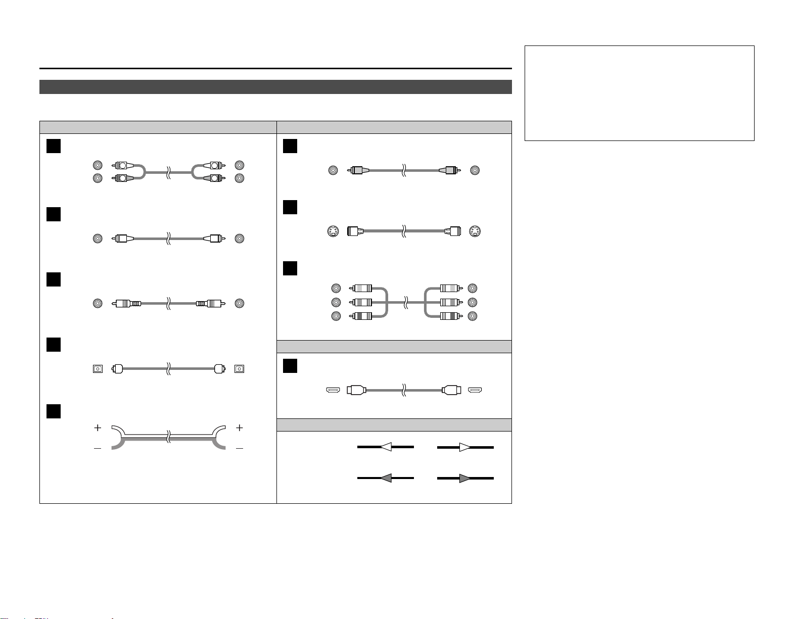
Cable indications
Signal direction
Audio and Video cable
The hookup diagrams on the subsequent pages assume the use of the following optional connection cables (not supplied).
Video cableAudio cable
NOTE:
• Do not plug in the power supply cord until all connections
have been completed.
• When making connections, also refer to the operating
instructions of the other components.
• Be sure to connect the left and right channels properly (left
with left, right with right).
• Do not bundle power cords together with speaker cables.
Doing so could result in humming or noise.
Analog terminal (Stereo)
A
R
L
R
L
(Orange)
Pin-plug cable
Analog terminal (Monaural, for subwoofer)
B
Pin-plug cable
Digital terminal (Coaxial)
C
Coaxial cable (75 Ω/ohms pin-plug cable)
(Yellow)
Digital terminal (Optical)
D
Optical cable (Optical fiber cable)
Speaker terminal
E
Speaker cable
Video terminal
F
HDMI terminal
I
HDMI cable
Video cable (75 Ω/ohms video pin-plug cable)
S-Video terminal
G
S-Video cable
Audio signal
Video signal
(White)
(Red)
Component video terminal
H
Component video cable
(Y)
(PB/CB)
(PR/CR)
(Green)
(Blue)
(Red)
IN OUT OUT IN
IN OUT OUT IN
Connecting Other Sources
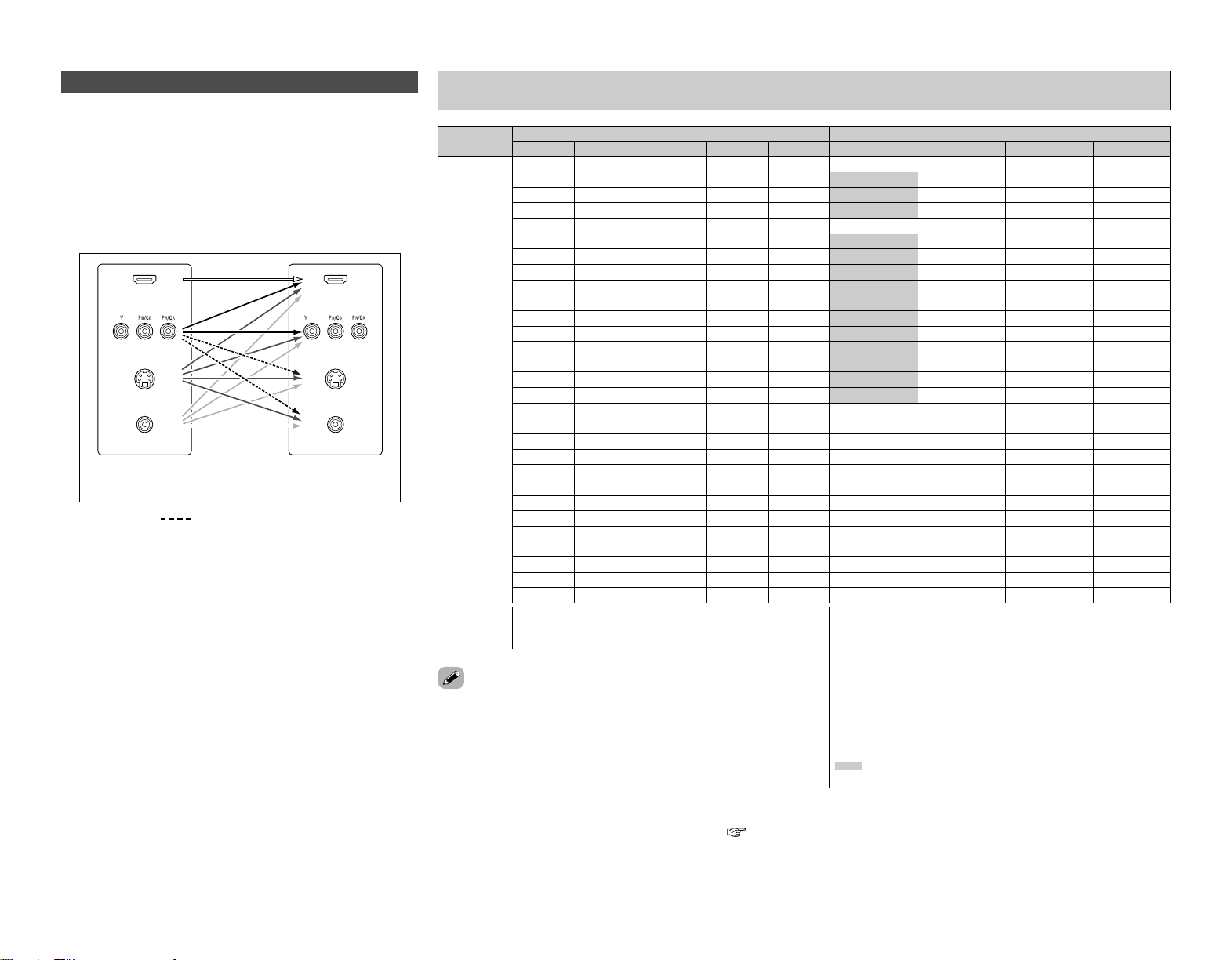
VIDEOS-VIDEOCOMPONENTHDMI
MONITOR OUT
VIDEOS-VIDEOCOMPONENTHDMI
Input signals
Video convert
14
Connecting Other Sources Connecting Other Sources
• Even if the formats of the video signals from the various players
differ, the different formats can be converted and the signals
output to the monitor from a single video output terminal. We
recommend outputting with the format offering the highest
quality video signals possible.
•With analog video signal connections, generally quality is higher
in the order shown below.
The flow of the video signals.
This unit’s input
terminals
This unit’s output
terminals
: only MAIN ZONE 480i/576i
(Component Video
terminals)
(Component Video
terminals)
(S-Video terminal)
(Video terminal)
The video conversion function
(HDMI terminal)
(HDMI
terminal)
(S-Video terminal)
(Video terminal)
ON
EE
✳3
S-VIDEO
S-VIDEO
S-VIDEO
S-VIDEO
EE
VIDEO
S-VIDEO
S-VIDEO
COMPONENT
COMPONENT
COMPONENT ✳1
COMPONENT ✳1
S-VIDEO
COMPONENT ✳2
COMPONENT ✳2
S-VIDEO
COMPONENT ✳2
COMPONENT ✳2
EE
EE
EE
EE
CC
(1080p)
CC
(480i/576i)
EE EE
EE CC
CC EE
CC CC
EE EE
CC
(480p ~ 720p)
EE EE
EE EE
EE
EE
EE
EE
EE
EE
EE
EE
VIDEO
S-VIDEO
S-VIDEO
COMPONENT
COMPONENT
EE EE
VIDEO VIDEO
S-VIDEO S-VIDEO
S-VIDEO S-VIDEO
EE EE
COMPONENT
EE EE
COMPONENT COMPONENT
EE
EE
CC
(1080p)
CC
(480p ~ 720p)
CC
(480i/576i)
CC
(480p ~ 720p)
EE CC
EE CC
EE CC
CC
(1080p)
CC EE
CC EE
EE
EE
EE
EE
EE
COMPONENT ✳1
COMPONENT ✳1
COMPONENT ✳1
COMPONENT ✳2
VIDEO VIDEO
VIDEO
COMPONENT VIDEO
COMPONENT ✳2
S-VIDEO S-VIDEO
S-VIDEO
VIDEO
CC
(480i/576i)
CC
(1080p)
CC
(480p ~ 720p)
EE
CC EE
CC CC
CC CC
CC
(480i/576i)
CC CC
EE EE
EE
EE
EE
CC
EECC
COMPONENT ✳2
COMPONENT ✳2
COMPONENT ✳2
EE
S-VIDEO
S-VIDEO S-VIDEO
S-VIDEO
COMPONENT ✳2
S-VIDEO
EE EE
HDMI
EE
EE
CC
(480i/576i)
EE CC
CC EE
CC CC
CC
(Other than 480i/576i)
EE EE
EE EE
CC
CC
CC
CC
CC
VIDEO
S-VIDEO
S-VIDEO
COMPONENT
VIDEO VIDEO
S-VIDEO S-VIDEO
S-VIDEO S-VIDEO
COMPONENT
EE EE
COMPONENT COMPONENT
HDMI ✳1
HDMI ✳2
HDMI ✳2
HDMI
HDMI
CC
(480p ~ 720p)
CC
(480i/576i)
CC
(Other than 480i/576i)
CC
(Other than 480i/576i)
EE
EE
CC
EE CC
CC EE
CC
(480i/576i)
CC EE
CC CC
CC
CC
CC
CC
CC
COMPONENT ✳1
COMPONENT ✳1
COMPONENT ✳1
COMPONENT ✳2
COMPONENT ✳2
EE
✳3
VIDEO
COMPONENT VIDEO
VIDEO
S-VIDEO S-VIDEO
COMPONENT ✳2
S-VIDEO S-VIDEO
S-VIDEO S-VIDEO
HDMI ✳1
HDMI ✳1
HDMI ✳1
HDMI ✳2
HDMI ✳2
HDMI ✳2
CC
(480i/576i)
CC
COMPONENT ✳2
S-VIDEO
VIDEO
S-VIDEO
HDMI ✳2
CC
CC
CC
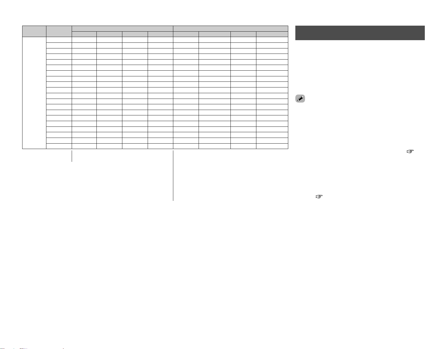
Relationship between the video input signal and monitor output according to the video
convert settings
CC
(1080p)
EE
: Not output
✳1:On screen display superimposed on video signal and
output.
✳2:On screen display superimposed on S-Video signal
and output.
✳3:Video signals are output when the “Analog to HDMI
convert” is set to “OFF”.
COMPONENT : On screen display only displayed for SYSTEM SETUP,
SURROUND PARAMETER and ON SCREEN buttons.
HDMI : The on screen display is displayed when the “Analog
to HDMI convert” is set to “ON”.
:Video signals are not output when the “Analog to
HDMI convert” is set to “OFF”.
CC
: Signal input
EE
: No signal
480p ~ 720p : 480p/576p/1080i/720p
• The MAIN ZONE video conversion function is compatible with the
following format: NTSC, PAL, SECAM, NTSC4.43, PAL-N, PAL-M and
PAL-60.
• When SECAM signals of video input are up-converted, the signals are
output in PAL format from the S-Video terminal.
• When the input signal is a component 480p, 576p,1080i or 720p signal,
the signal up-converted to HDMI is output with that resolution.
• When the input signal is a video, S-Video or component 480i or 576i
signals, the signal up-converted to HDMI is output according to the
setting made at “i/p Convert” under “HDMI Out Setup” ( page 51).
• Signals up-converted to HDMI are output to the HDMI monitor with the
resolution at which they are input. Note that resolutions of 1080p are not
handled.
VIDEOS-VIDEOHDMI COMPONENT
MONITOR OUT
VIDEOS-VIDEOCOMPONENTHDMI
Input signals
S-VIDEO
MONITOR OUT
Video convert
15
Connecting Other Sources Connecting Other Sources
2 On screen display for component video outputs
and HDMI output
• When viewing component video signals or HDMI signals via
the AVR-2807, the on screen display is displayed on the monitor
when the “System Setup” operations are performed and when
the remote control unit’s ON SCREEN button is operated.
• When only component video signals are input to the AVR-2807,
the characters of the on screen display are not displayed over
the picture.
• The AVR-2807’s video up-conversion function lets you output
analog video input signals (component – 480i/576i, 480p/576p,
1080i or 720p; S-Video and composite video – 480i/576i) to the
HDMI monitor output terminal.
• On the AVR-2807, it is possible to convert 480i/576i component
video, S-Video and composite video input signals to 480p/576p
format and output them from the HDMI monitor output
terminal.
• The resolutions with which the monitor is compatible can be
checked using the STATUS button on the main unit or the ON
SCREEN button on the remote control unit.
• It is not possible to down-convert from HDMI input signals to
the component, S-Video or composite video monitor output
terminals.
• If you do not want to use the function for converting analog
video signals to HDMI signals, select “OFF” for “Analog to
HDMI Convert” at “Setting the HDMI Out Setup”( page
51).
•Video down conversion to the MAIN ZONE’s monitor output is
only possible when the component video input resolution is
480i (interlaced standard definition video – NTSC format, for
North America) or 576i (interlaced standard definition video –
PAL format, for Europe and other countries).
•To set the video conversion function for the MAIN ZONE to
“OFF” ( page 50).
The analog video to HDMI conversion
function
OFF
–
–
EE
EE
EE
EE
EE
EE
EE
EE
HDMI
HDMI
HDMI
HDMI
HDMI
HDMI
EE
EE
EE
EE
EE
CC
EE EE
EE CC
CC EE
CC CC
CC CC
CC EE EE
EE CC
EE
EE
EE
EE
EE
EE
EE
EE
EE
EE
EE
EE
COMPONENT ✳1
EE EE
EE
VIDEO
S-VIDEO
EE
S-VIDEO
VIDEO ✳2
– VIDEO
COMPONENT
EE EE
EE
VIDEO
EE
EE
CC
CC
CC
EE
CC EE
CC CC
CC
CC
EE EE EE
EE CC
EE
EE
EE
CC
CC
COMPONENT ✳2
COMPONENT ✳2
COMPONENT ✳1
EE
S-VIDEO
EE
S-VIDEO
VIDEO ✳2
– VIDEO
EE EE EE
EE
VIDEO
EE
EE
EE
CC EE
CC CC
CC CC
CC EE EE
CC
CC
CC
CC
EE
EE
EE
S-VIDEO
EE
S-VIDEO
VIDEO ✳2
– VIDEO
COMPONENT
EE EE
–
Used
Not used
–
–
–
Used
Not used
–
–
Used
Not used
–
–
HDMI
HDMI
HDMI
CC
CC
EE CC
CC EE
CC CC
CC CC CC
CC
CC
CC
CC
COMPONENT ✳1
COMPONENT ✳2
COMPONENT ✳2
EE
VIDEO
S-VIDEO
EE
S-VIDEO
VIDEO ✳2
COMPONENT ✳1
– VIDEO
–
–
Used
Not used
CC
HDMI
EE
: Not output
✳1:On screen display superimposed on video
signal and output.
✳2:On screen display superimposed on S-Video
signal and output.
COMPONENT : On screen display only displayed for SYSTEM
SETUP, SURROUND PARAMETER and ON SCREEN
buttons.
HDMI : The on screen display is displayed when the
“Analog to HDMI convert” is set to “ON”.
CC
: Signal input
EE
: No signal
16
Connecting Other Sources Connecting Other Sources
Connecting equipment with HDMI terminals
[To convert analog video signals to HDMI signals]
• The AVR-2807 is equipped with a function for converting analog video signals into HDMI signals.
You can do this by either a component or a video or a S-Video connection.
•Audio signals are not output from the HDMI monitor output terminal, so also make analog or
digital audio connections. To play sound using digital audio connections, assign the digital terminal
(coaxial or optical) at “Setting the Digital In Assignment” ( page 47).
Connecting a TV tuner
• For best picture quality choose the component video connection to your TV tuner. S-Video and
composite video outputs are also provided if your TV tuner does not have component video
inputs.
•To connect the digital audio output from the TV tuner, you can choose from either the coaxial or
the optical connections. If you choose to use the coaxial or the optical connection, it needs to be
assigned. For more information about Digital Input Assignment ( page 47).
Connecting a DBS tuner
• For best picture quality choose the component video connection to your DBS tuner. S-Video and
composite video outputs are also provided.
•To connect the digital audio output from the DBS tuner, you can choose from either the coaxial
or optical connections. If you choose to use the coaxial connection, it needs to be assigned. For
more information about Digital Input Assignment ( page 47).
• When “OFF” is set at “i/p Convert” under “Setting the HDMI Out Setup”, use a monitor
compatible with input resolutions of 480i/576i.
• If your monitor is not equipped with an HDMI terminal, connect the AVR-2807 to the monitor
using the component video, S-Video, or composite video terminals.
Monitor
HDMI
IN
DVD player
S VIDEO
OUT
COAXIAL
OUT
R
L
AUDIO OUT
VIDEO
OUT
COMPONENT VIDEO OUT
Y
P
B
PR
OPTICAL
OUT
I
R
L
R
L
F
H
G
A
C
D
F
G
A
TV tuner
S VIDEO
OUT
R
L
AUDIO OUT
VIDEO
OUT
COMPONENT VIDEO OUT
Y
P
B
PR
R
L
R
L
H
F
G
A
DBS / BS Tuner
S VIDEO
OUT
R
L
AUDIO OUT
VIDEO
OUT
COMPONENT VIDEO OUT
Y
P
B
PR
OPTICAL
OUT
D
R
L
R
L
H
17
Connecting Other Sources Connecting Other Sources
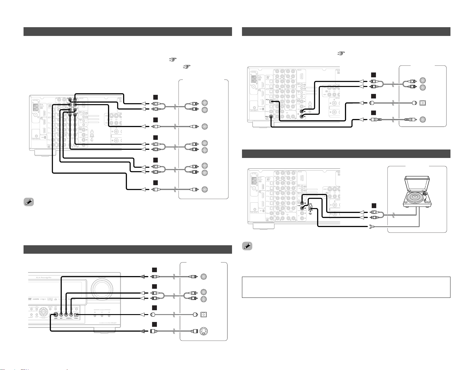
Connecting a video camera or video game
Connecting the external inputs (EXT. IN) terminals
• These terminals are for inputting multi-channel audio signals from an outboard decoder, or a
component with a different type of multi-channel decoder, such as a DVD-Audio player, or a multi-
channel Super Audio CD player, or other future multi-channel sound format decoder.
• The video signal connection is the same as that for a DVD player ( page 8).
• For instructions on playback using the external input (EXT. IN) terminals ( page 23).
•With discs on which special copyright protection measures have been taken, however, the digital
signals may not be output from the DVD player. In this case, connect the DVD player’s analog
multi-channel output to the AVR-2807’s EXT. IN terminals for playback. Also refer to your DVD
player’s operating instructions.
NOTE:
• If humming or other noise is generated when the ground wire is connected to the SIGNAL
GND terminal, disconnect the ground wire.
Connecting a turntable
Connecting a CD player
To connect the digital audio output from the CD player, you can choose from either the coaxial or
optical connections. If you choose to use the optical connection, it needs to be assigned. For more
information about Digital Input Assignment ( page 47).
• The phono input can accept signals from moving magnet (MM) and high output moving coil (MC)
phono cartridges. If your turntable is equipped with a low output MC cartridge, you will need to
use a separate MC head amplifier or step-up MC transformer.
DVD Audio-Video /
Super Audio CD Player /
External decoder
R
SURROUND
BACK
L
R
SURROUND
L
R
FRONT
L
7.1ch AUDIO OUT
CENTER
SUB-
WOOFER
R
L
R
L
R
L
R
L
B
A
B
A
R
L
R
L
A
Video camera /
Video game
S VIDEO
OUT
R
L
AUDIO OUT
VIDEO
OUT
OPTICAL
OUT
R
L
R
L
F
G
A
D
R
L
AUDIO OUT
CD player
COAXIAL
OUT
OPTICAL
OUT
R
L
R
L
A
C
D
AUDIO OUT
GND
Turntable
(MM cartridge)
R
L
A

18
Connecting Other Sources Connecting Other Sources
Connecting a DVD recorder
• For best picture quality choose the component video connection to your DVD recorder. S-Video
and composite video outputs are also provided. If you choose to use the component video
connection, it needs to be assigned. For more information about Component Input Assignment
( page 50).
• If you wish to perform analog dubbing from a digital sources, such as a DVD recorder to an analog
recorder such as a cassette deck, you will needs connect the analog inputs and outputs as shown
below, in addition to the digital audio connections.
NOTE:
• Do not connect the output of the component connected to the OPTICAL 3 OUT terminal on
the AVR-2807’s rear panel to any terminal other than the OPTICAL 3 IN terminal.
Connecting a VCR
There are 2 sets of video deck (VCR) terminals, so 2 video decks can be connected for
simultaneous recording or video copying.
• When recording to a VCR, it is necessary that the type of cable used with the playback source
equipment be the same type that is connected to the AVR-2807 VCR-1 (to 2) OUTPUT terminal.
Example: VCR-2 IN → S-Video cable : VCR-2 OUT → S-Video cable
VCR-2 IN → Video cable : VCR-2 OUT → Video cable
•When recording to a DVD recorder, it is necessary that the type of cable used with the playback
source equipment be the same type that is connected to the AVR-2807 VCR-1 (to 2) OUTPUT
terminal.
Example: VCR-1 IN → S-Video cable : VCR-1 OUT → S-Video cable
VCR-1 IN → Video cable : VCR-1 OUT → Video cable
Connecting a tape deck
DVD recorder
S VIDEO
OUT
S VIDEO
IN
R
L
AUDIO IN
R
L
AUDIO OUT
VIDEO
OUT
VIDEO
IN
OPTICAL
IN
OPTICAL
OUT
R
L
R
L
F
F
G
G
A
R
L
R
L
A
D
D
COMPONENT VIDEO OUT
Y
P
B
PR
H
Video deck
R
L
AUDIO IN
R
L
AUDIO OUT
VIDEO
IN
S VIDEO
OUT
S VIDEO
IN
VIDEO
OUT
R
L
R
L
F
G
F
G
A
R
L
R
L
A
R
L
AUDIO IN
R
L
AUDIO OUT
Tape deck
R
L
R
L
A
R
L
R
L
A
19
Connecting Other Sources Connecting Other Sources
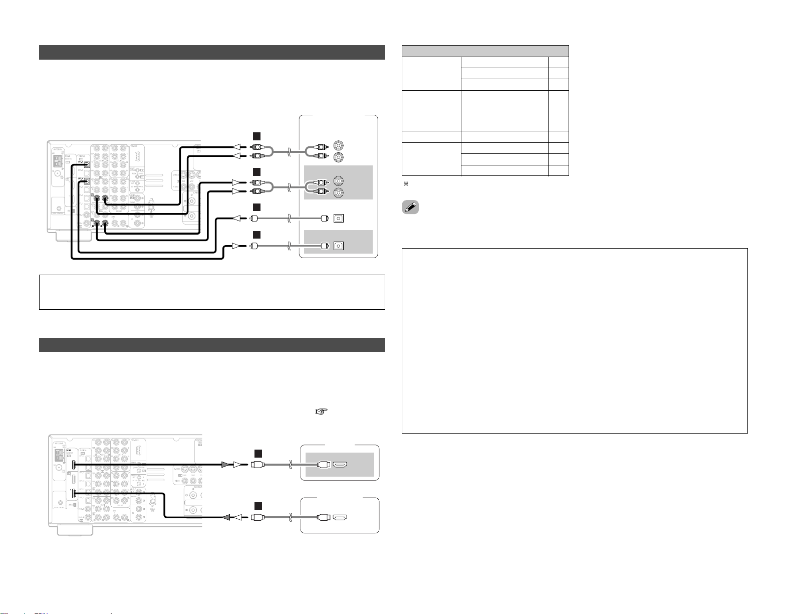
Connecting a CD recorder or MD recorder
If you wish to perform analog dubbing from a digital source, such as a CD or MD recorder to an
analog recorder such as a cassette deck, you will need to connect the analog inputs and outputs
as shown below, in addition to the digital audio connections.
NOTE:
• Do not connect the output of the component connected to the OPTICAL 4 OUT terminal on
the AVR-2807’s rear panel to any terminal other than the OPTICAL 4 IN terminal.
Connecting equipment with HDMI terminals
•A simple 1-cable connection (using a commercially available cable) with a device having an HDMI
(High-Definition Multimedia Interface) terminal allows digital transfer of the digital images of DVD-
Video and other sources, and the multi-channel sound of DVD-Audio and DVD-Video.
•To provide audio output from AVR-2807’s audio output terminal, select “Amp” at the “HDMI In
Assign”.
To provide audio output from the TV, select “TV” at the “HDMI In Assign” ( page 49, 50).
Input signals
CC
DVD-Video
LINEAR PCM
DTS
Dolby Digital
DVD-Audio
CC
LINEAR PCM
PACKED PCM
(with CPPM /
without CPPM)
CC
CC
CC
CD LINEAR PCM
EE
Super Audio
CD
Multi area
CD area
Stereo area
EE
CC
2 Copyright Protection System
To play back the digital video and audio of DVD-
Video and DVD-Audio through an HDMI/DVI-D
connection, both the connected player and
monitor are required to support a copyright
protection system called HDCP (High-
bandwidth Digital Content Protection System).
HDCP is copy protection technology that
comprises data encryption and authentication
of the partner equipment.
The AVR-2807 supports HDCP. Please see the
user’s manual of your video display for more
information about this.
The AVR-2807 is HDMI Ver. 1.1 compatible.
• If your digital monitor or DVD player only supports DVI-D, please obtain and use an HDMI-DVI
conversion cable or adaptor, available from your dealer.
2 Connections with an HDMI/DVI-D conversion cable (adapter)
• The HDMI video stream signals (video signals) are theoretically compatible with DVI-D. When
connecting to a monitor, etc., equipped with DVI-D terminals, it is possible to connect using an
HDMI/DVI-D conversion cable, but depending on the combination of devices used the image
might not be output.
• When using an HDMI/DVI-D conversion adapter, the image may not be output properly due to
poor contact with the connected cable, etc..
NOTE:
• The audio signals on the multi/stereo area of Super Audio CDs are not output. If the Super
Audio CD is a hybrid CD, only the audio signals in the CD area are output.
• Use a compatible player to play DVD-Audio discs that are copyright protected by CPPM.
• Among the devices that support HDMI, some devices can control other devices via the HDMI
terminal; however, the AVR-2807 cannot be controlled by another device via the HDMI
terminal.
• The audio signals from the HDMI terminal (including the sampling frequency and bit length)
may be limited by the equipment that is connected.
• The video signals are not output properly if a device not compatible with HDCP is used.
• When “OFF” is set at “i/p Convert” under “Setting the HDMI Out Setup”, use a monitor
compatible with input resolutions of 480i/576i.
• The video signals input from the HDMI input terminals are output to the HDMI monitor with
their original resolution, so the image will not be displayed if the resolutions of the input signal
and the monitor being used are not matched. In this case, change the setting of the resolution
on the source device (player) to one which the monitor can handle.
• For stable signal transfer, we recommend using cables that are a maximum of 5 meters in
length.
R
L
AUDIO IN
R
L
AUDIO OUT
CD recorder /
MD recorder
OPTICAL
OUT
OPTICAL
IN
R
L
R
L
A
R
L
R
L
A
D
D
DVD player
HDMI
OUT
Monitor
HDMI
IN
I
I
20
Connecting Other Sources Connecting Other Sources
1
4
2
3
2 AM loop antenna assembly
Connect to the AM
antenna terminals.
Remove the vinyl tie
and take out the
connection line.
Bend in the reverse
direction.
a. With the antenna
on top any stable
surface.
b. With the antenna
attached to a wall.
Mount
Installation hole Mount on wall, etc.
NOTE:
• Do not connect 2 FM antennas
simultaneously.
•Even if an external AM antenna is used, do
not disconnect the AM loop antenna.
• Make sure the AM loop antenna lead
terminals do not touch metal parts of the
panel.
An FM antenna cable plug can be connected directly.
Connecting the antenna terminals
Direction of broadcasting station
75 Ω/ohms
Coaxial cable
FM antenna
FM indoor antenna
(Supplied)
AM loop antenna
(Supplied)
AM outdoor antenna
Ground
Connection of AM antennas
1. Push the
lever.
2. Insert the
conductor.
3. Return the
lever.
Note to CATV system installer:
This reminder is provided to call the CATV
system installer’s attention to Article 820-40
of the NEC which provides guidelines for
proper grounding and, in particular, specifies
that the cable ground shall be connected to
the grounding system of the building, as
close to the point of cable entry as practical.
Connecting the XM terminal
•AVR-2807 is the XM Ready® receiver. You can receive XM Satellite Radio® by connecting to the
XM Connect-and-Play
TM
(sold separately) and subscribing the XM service.
• Plug the XM Connect-and-Play antenna into XM connector on the rear panel.
• Position the XM Connect-and-Play antenna near a south-facing window to receive the best signal.
For details, see “XM Satellite Radio” ( page 36, 37).
When making connections, also refer to the operating instructions of the XM Connect-and-Play
antenna.
NOTE:
• Keep the power supply cord unplugged until the XM Connect-and-Play antenna connection
have been completed.
XM Connect-and
-Play Antenna
XM
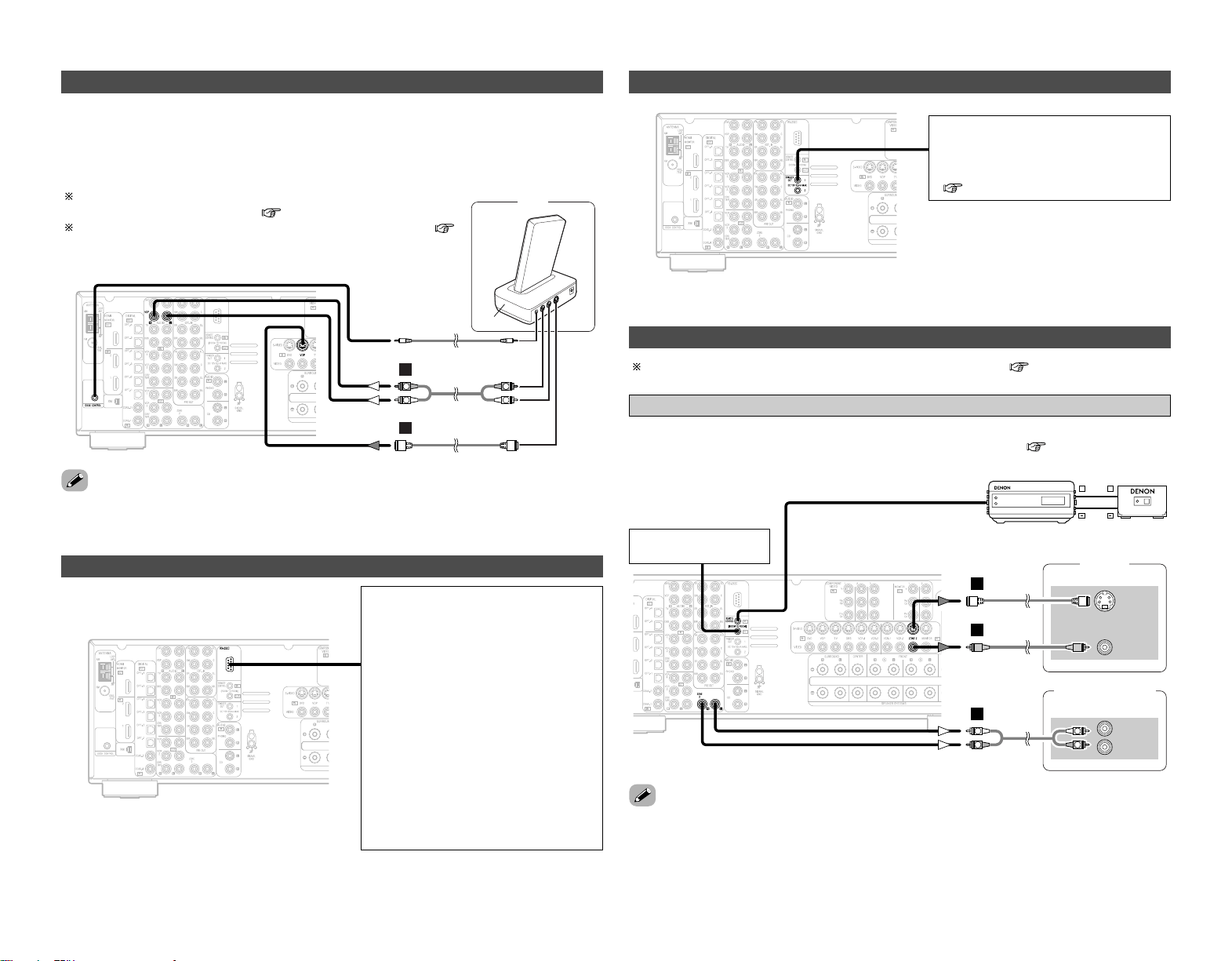
21
Connecting Other Sources Connecting Other Sources
For instructions on operations using the MULTI ZONE functions ( page 40, 41).
Connecting the MULTI ZONE terminals
• If another pre-main (integrated) amplifier is connected, the ZONE2 out (fixed level) terminals can
be used to play a different program source in ZONE2 the same time ( page 40).
ZONE2 out connections
• For the AUDIO output, use high quality pin-plug cables and wire in such a way that there is no
humming or noise.
• For instructions on installation and operation of separately sold devices, refer to the devices’
operating instructions.
Monitor
(ZONE2)
S-VIDEO
IN
VIDEO
IN
AUX OUT
Premain amplifier
(ZONE2)
R
L
IN
G
F
R
L
R
L
A
+
+
Extension terminal
for future use.
Input Output
RC-616
Infrared retransmitter
RC-617
Infrared sensor
Connecting the TRIGGER OUT jacks
Turn the DC 12 V voltage on and off for
the individual functions and surround
modes.
For details, see “Setting the Trigger Out”
( page 55).
Connecting the RS-232C terminal
This is a control expansion terminal for
factory use only. Consult you dealer for
details.
Perform the following operation before
using an external controller connected to
the RS-232C terminal:
1. Press the ON/STANDBY button on the
main unit and set the unit to the
operating mode.
2. Perform the operation to turn off the
power from the external control.
3. Check that the product has been set
to the standby mode.
After checking the above, check the
connections of the external controller.
Operation is possible.
Connecting the iPod
®
iPod
L
R
L
R
A
G
AUDIO OUT
S-VIDEO OUT
ASD-1R
When using an iPod, you must connect the DENON original Control Dock for iPod and the DOCK
CONTROL jack on the AVR-2807 with a mini-jack and assign the iPod to any AUDIO and/or S-
VIDEO terminal(s).
The diagram below shows an example of connections for when the iPod is assigned to the VDP
terminal.
For instructions on assigning the iPod to a specific terminal, see
“Setting the iPod Assignment” ( page 47).
For instructions on playing the iPod, see “Playing the iPod” (
page 39).
• The optional standard Control Dock for iPod is DENON ASD-1R sold separately.
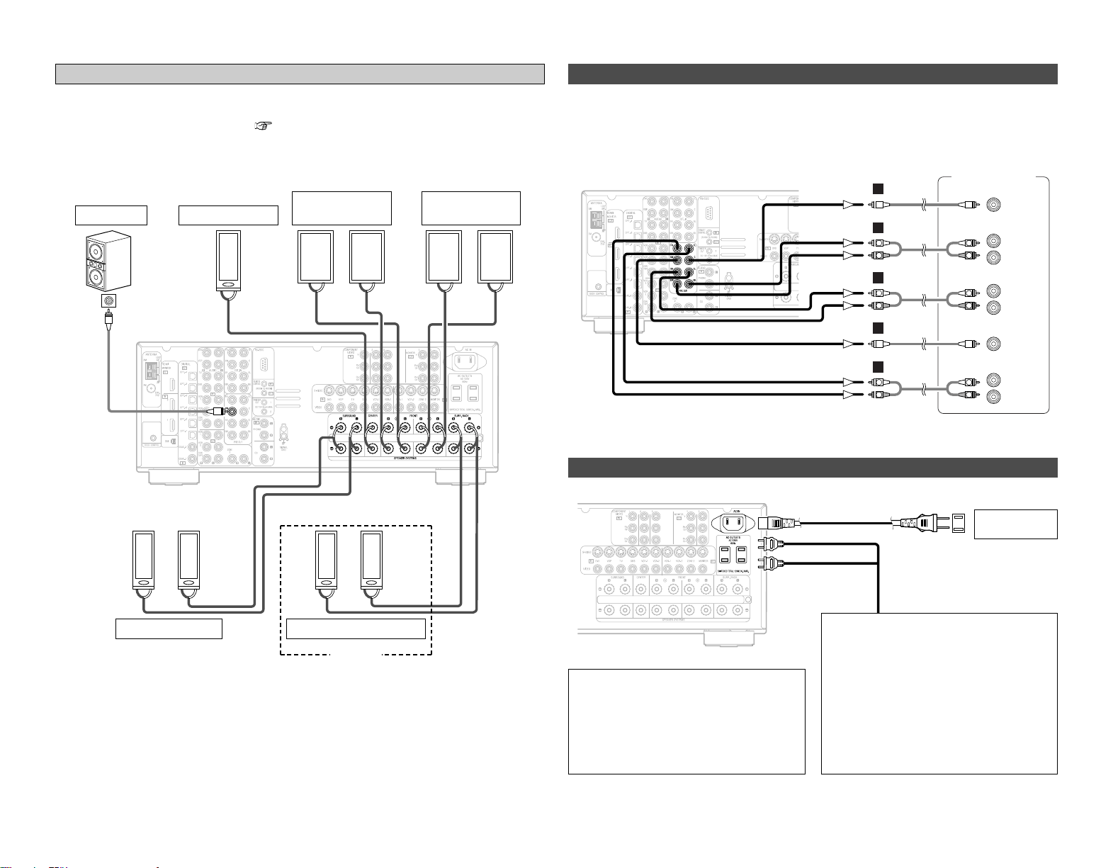
><>< ><><
><
><><><><
IN
(
L
) (
R
) (
L
) (
R
)
(
L
) (
R
) (
L
) (
R
)
22
Connecting Other Sources Connecting Other Sources
• Use these terminals if you wish to connect external power amplifier(s) to increase the power of
the front, center, surround and surround back sound channels, or for connection to powered
loudspeakers.
• When using only one surround back speaker, connect it to the left channel.
Connecting the PRE OUT terminals
Connecting the power supply cord
Connection
terminal for
subwoofer
with built-in
amplifier.
Front speaker
(B)
Surround speaker
Front speaker
(A)
Subwoofer
ZONE2 Front speaker
Center speaker
• When the surround back’s power amplifier is assigned to the ZONE2 output channel at “Power
Amp Assign” in the “System Setup Menu”, the surround back speaker terminals can be used
as the ZONE2 speaker out terminals ( page 54).
• The connections diagram below is an example for when the surround back speaker is assigned
to the ZONE2 stereo 2 channel.
In this case, surround back speaker out can not be used for MAIN ZONE.
ZONE2 speaker out connections
ZONE2
Power amplifier
R
SURROUND
BACK
L
R
SURROUND
L
R
FRONT
L
CENTER
SUB-
WOOFER
R
L
R
L
B
A
B
A
R
L
R
L
R
L
R
L
A
AC 120 V, 60 Hz
AC outlet
(wall)
Power supply cord
(Supplied)
NOTE:
• Insert the plugs securely. Incomplete
connections will result in the generation of
noise.
• Only use the AC OUTLETS for audio
equipment. Never use it for hair driers,
monitors or other electrical appliances.
AC OUTLETS
• SWITCHED (total capacity – 120 W (1A.))
The power to the outlet is turned on and
off in conjunction with the POWER switch
on the main unit, and when the power is
switched between on and standby from
the remote control unit.
No power is supplied from this outlet
when this unit’s power is at standby. Never
connect equipment whose total power
consumption exceeds 120 W (1A.).

Basic Operation
23
Basic Operation
<SOURCE> INPUT MODE VOLUME<EXT.IN>
<ANALOG>
FUNCTION
SURROUND
PARAMETER
INPUT MODE
VOLUME
SURROUND
PARAMETER
FUNCTION
Playing the input source
Use FUNCTION to select the input source you
want to play.
To select the input source when ZONE2/REC SELECT,
VIDEO SELECT or TUNING PRESET is selected, press
<
SOURCE
>
then operate
<
FUNCTION
>
.
Start playback on the selected component.
For operating instructions, refer to the component’s manual.
1
3
Press INPUT MODE.
AUTO (All auto mode):
The type of input signal is detected and the AVR-2807’s
surround mode is switched automatically. Can be selected for
sources for which the “Digital In Assign”
(
page 47) is
made.
The mode switches automatically to DTS/ Dolby Digital/ PCM.
The input switches to the analog input terminals is no digital
signals are being input.
ANALOG (exclusive analog audio signal playback mode) and
EXT. IN (External decoder input terminal selection mode):
The signals input to the various input terminals are played.
PCM (exclusive PCM signal playback mode) and
DTS (exclusive DTS signal playback mode):
Played when the various signals are input. Noise may be
generated when a mode different from the input signal is set.
AUTO
EXT. IN ANALOG
PCM DTS
2
Use VOLUME to adjust the volume.
• The volume level is displayed on the master volume level
display.
The volume can be adjusted between the range of –80 ~ 0
~ 18 dB. Depending on the channel level settings and the
different surround mode settings and when in the down-mix
mode, it may not be possible to adjust the volume to 18 dB.
4
NOTE:
• When the input mode is set to the external input (EXT. IN),
the surround mode cannot be set.
• In play modes other than the external input mode, the
signals connected to these terminals cannot be played.
Cautions when playing DTS sources:
• For DTS sources, be sure to connect the device to the digital
input terminal and set “AUTO” or “DTS” for the input
source. Noise will be generated if you play in the ANALOG
or PCM mode.
• When playing DTS signals in the “AUTO” mode, noise may
be generated when you first start playing and during
searching. If so, play in the “DTS” mode.
• Canceling the EXT. IN mode:
Press INPUT MODE or
<
ANALOG
>
to switch to the desired input
mode.
•To use the EXT. IN mode together with a picture, select the input
source to which the video signal is connected first, then set the
input mode.
• The “DIG.” indicator lights when digital signals are being input
properly. If the “DIG.” indicator does not light, check whether
the “Digital In Assign” ( page 47) and connections are
correct.
About the button names in this explanation
<>: Buttons on the main unit
[]: Buttons on the remote control unit
Button name only :
Buttons on the main unit and remote control unit
Press
<
ANALOG
>
to select “ANALOG”,
<
EXT. IN
>
to select
“EXT. IN”.
To lower the subwoofer channel level in the EXT. IN mode,
press SURROUND PARAMETER and select “SW. ATT”.
For some players the playback level of the SW channel may
seen strong. If so, set to “ON”.
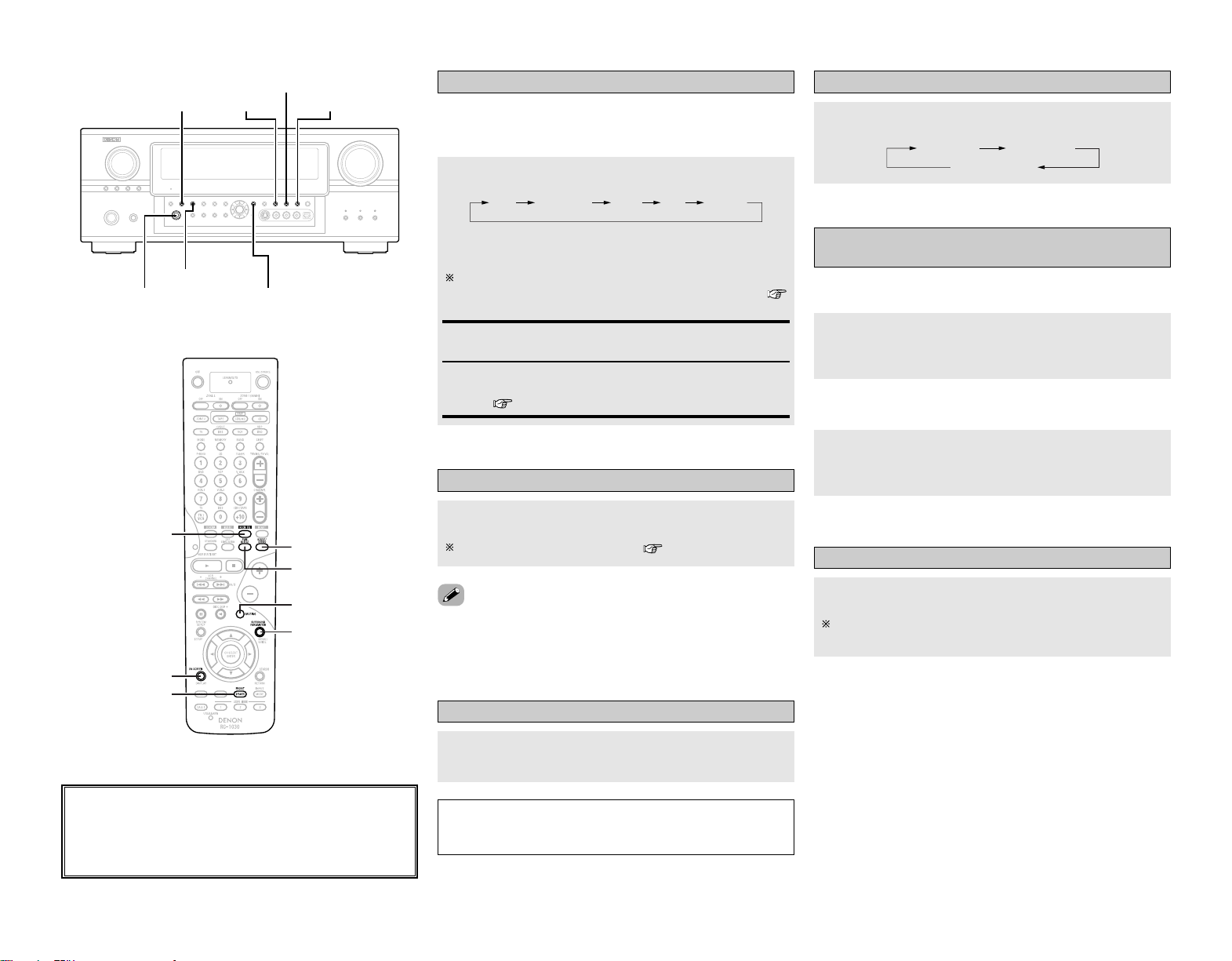
24
Basic Operation Basic Operation
Selecting the room equalizer mode
The room equalizer function offers 3 correction curves:
“Audyssey”, “Front” and “Flat”. These modes can be selected
after performing the auto setup procedure.
OFF Audyssey Front Flat Manual
Press ROOM EQ.
• The “MultEQ XT” indicator lights green when “Audyssey” is
selected, red when “Front” or “Flat” is selected.
The indicator lights red if the speaker settings are changed
after the auto setup measurements have been made (
page 56 ~ 59).
Audyssey, Front, Flat:
See page 60.
Manual:
Selects the setting value that was set in the Manual Equalizer
Setup ( page 53, 54).
Turning the sound off temporarily (MUTING)
Press [MUTING].
You can adjust the muting level ( page 55).
• Canceling MUTING mode:
To cancel the muting mode, either press [MUTING] or adjust the
volume.
Connect the headphones to
<
PHONES
>
.
• No sound is produced from the speakers automatically.
NOTE:
•To prevent hearing loss, be careful not to raise the volume
level excessively when using headphones.
Listening over headphones
Switching the front speakers
Press [SPEAKER].
FRONT A
FRONT A+B
FRONT B
2 On screen display
Checking the currently playing program
source, etc.
Press [ON SCREEN].
• The current program source and various settings are
displayed on the monitor screen.
2 Front panel display
Press
<
STATUS
>
.
• The current program source and various settings are indicated
on the display.
Switching the brightness of the display
Press
<
DIMMER
>
.
The brightness of the display can be adjusted in 3 steps. The
display can also be turned off.
About the button names in this explanation
<>: Buttons on the main unit
[]: Buttons on the remote control unit
Button name only :
Buttons on the main unit and remote control unit
<PHONES> SURROUND
PARAMETER
<STATUS>
<DIMMER> ROOM EQ
DIRECT/STEREO
PURE DIRECT
[MUTING]
SURROUND
PARAMETER
ROOM EQ
[ON SCREEN]
[SPEAKER]
DIRECT/STEREO
PURE DIRECT

25
Sources recorded in stereo
Sources recorded in monaural
PURE DIRECT
• Use this mode to play analog input music sources with
extremely high quality.
DIRECT / STEREO
•Effective for achieving pure playback.
• If there is no need for tone control or distribution of
the low frequencies in function of the speaker
configuration, select the DIRECT mode to achieve the
best sound quality.
DENON Original Surround Modes ( page 32, 33)
• Select these for 7.1-channel playback with sources
recorded in stereo or monaural.
•The effects are different for each of the surround
modes. Select the one most suited for the source
being used.
DTS NEO:6 ( page 28)
• This is a surround mode for playing 6.1- or 7.1-channel
stereo sources developed by Digital Theater Systems.
• One of 2 playing modes, MUSIC (for music sources)
or CINEMA (for movie sources), can be selected
according to your preferences.
DOLBY PRO LOGIC IIx
*
( page 27)
• Developed by Dolby Laboratories, this surround mode
provides 7.1-channel surround sound with
conventional stereo (2-channel) sources.
• Select CINEMA mode for movie surround
soundtracks, MUSIC for music sources, and GAME
for 2-channel game box audio sources.
Basic Operation Basic Operation
• Surround modes marked with an asterisk (*) cannot be used
when the surround back speaker is set to “NONE”.
• The “+PLII x Cinema” mode cannot be selected when only one
surround back speaker is being used.
2 DIRECT mode
This mode is for playing with high quality sound. The audio
signals are transmitted directly, without passing through the tone
circuits, etc.
Selecting the play mode
(PURE DIRECT / DIRECT / STEREO)
• The system setup function cannot be used when the PURE
DIRECT mode is set. To use the system setup function, cancel
the PURE DIRECT mode.
• If the HDMI input terminal is selected, video outputs are output
in the PURE DIRECT mode.
• The channel level and surround parameters in the PURE
DIRECT mode are the same as in the DIRECT mode.
The AVR-2807 is equipped with 3 2-channel playback modes
exclusively for music. Select the mode to suit your tastes.
Press DIRECT/STEREO to select “DIRECT”.
STEREODIRECT
2 PURE DIRECT mode
This mode reproduces the sound with extremely high quality.
The audio signals do not pass through the tone circuits, etc., and
the display and surrounding circuits that could affect the audio
signals are turned “OFF”.
Press PURE DIRECT.
2 STEREO mode
Use this mode to adjust the tone and achieve the desired sound.
Press DIRECT/STEREO to select “STEREO”.
Using the surround modes
Types of surround modes and their features
The AVR-2807 is equipped with many surround modes. We
recommend using the surround modes as described below in
order to achieve the maximum effect for the specific signal
source.
is a 6.1-channel/7.1-channel surround mode.
Sources recorded in Dolby Digital EX
DOLBY DIGITAL EX / +PLIIx
*
( page 26)
• This mode is optimized for playing sources recorded in
Dolby Digital EX.
Sources recorded in DTS-ES
DTS-ES DSCRT 6.1 / MTRX 6.1, +PLIIx
*
( page 26)
• This is the optimum mode for playing sources
recorded in DTS-ES.
Dolby Digital or DTS Surround (5.1 ch sources)
2 ch sources recorded in Dolby Surround
WIDE SCREEN ( page 32, 33)
•Effective for 2-channel sources recorded in Dolby
Surround or for 7.1-channel playback with 5.1-channel
sources.
DOLBY DIGITAL / DOLBY DIGITAL+PLII x
*
/
DTS SURROUND / DTS 96/24 / DTS+PLIIx
*
/
DTS+NEO:6 ( page 26)
• This mode is optimized for playing 5.1-channel or 7.1-
channel music.
• For Dolby Surround recording sources, Dolby Pro
Logic II playback is conducted.
When press SURROUND PARAMETER:
The subwoofer output can be controlled directly.
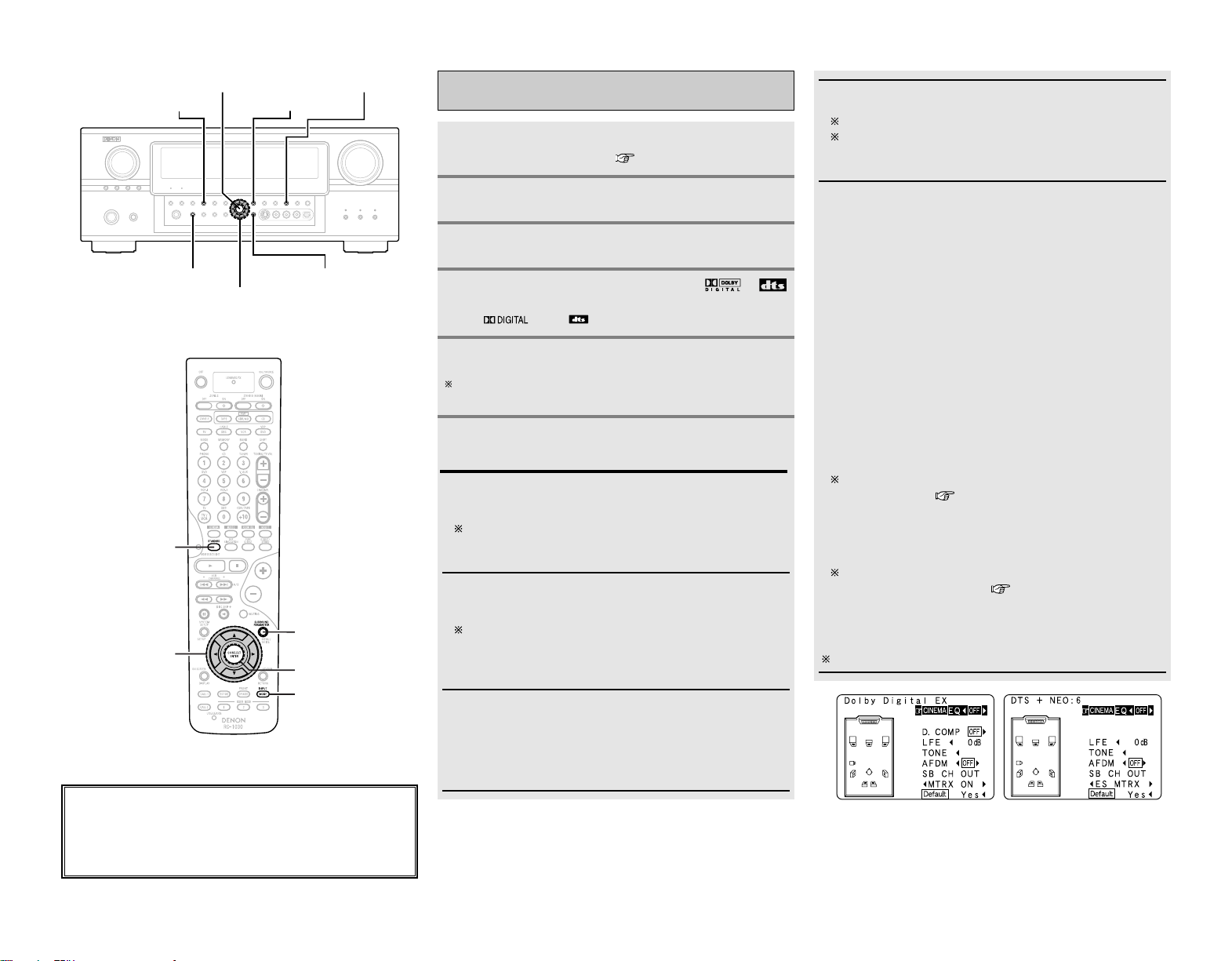
26
Basic Operation Basic Operation
About the button names in this explanation
<>: Buttons on the main unit
[]: Buttons on the remote control unit
Button name only :
Buttons on the main unit and remote control unit
D
H
F
G
STANDARD
ENTER
SURROUND
PARAMETER
<STATUS>
<SURROUND BACK>
INPUT MODE
SURROUND
PARAMETER
STANDARD
ENTER
D
H
F
G
INPUT MODE
Selecting the Dolby Digital and DTS
Surround mode (only with digital input)
Play a program source with the ,
mark.
•“ ” or “ ” lights, depending on the source.
Press SURROUND PARAMETER.
The surround back channel can be switched on and off using
<
SURROUND BACK
>
.
Press
DD HH
to select the item, then press
FF GG
to
set.
Press STANDARD to select “STANDARD”.
3
6
5
4
Select an input source for which digital (COAXIAL,
OPTICAL etc.) is set ( page 47 or 49 ~ 50).
1
Press INPUT MODE to select “AUTO”.
2
CINEMA EQ.:
Use this if movie dialogues sound harsh to lower the treble
sound.
Effective source / mode
Dolby Pro Logic II x / Dolby Pro Logic / Dolby Digital /
DTS Surround / DTS NEO:6 / WIDE SCREEN
D.COMP.:
The dynamic range is compressed. Select one of 4 modes:
“OFF”, “LOW”, “MID” (middle) or “HI” (high).
Effective source / mode
Dolby Digital /
DTS (For DTS sources, only displayed for compatible
software.)
LFE:
To play the various types of software properly, we
recommend setting to the values shown below.
•To play Dolby Digital software: “0 dB”
•To play DTS movie software: “0 dB”
•To play DTS music software: “–10 dB”
TONE:
Adjust the tone control.
Can be set in surround modes other than direct mode.
Can be set separately for the different surround modes.
(Adjusted together for the Dolby/DTS SURROUND
modes.)
SB CH OUT:
Select the play mode or surround back channel playback
method.
(1) For multi-channel sources
• SB OFF (OFF):
Not played.
• NON MTRX:
Surround channel signal played.
• MTRX ON:
Surround channel signal played with digital matrix processing.
• ES MTRX:
DTS signal played with digital matrix processing.
• ES DSCRT:
Signal included in DTS-ES discrete 6.1-channel sources
played.
• PL
II x CINEMA:
Decoded in Dolby Pro Logic II x Cinema mode, surround back
signal played.
Set the surround back speaker to “2spkrs” at “Speaker
Configuration” ( page 56, 57)
• PLII x MUSIC:
Decoded in Dolby Pro Logic II x Music mode, surround back
signal played.
Set the surround back speaker to “1spkr” or “2spkrs” at
“Speaker Configuration” ( page 56, 57)
(2) For 2-channel sources
• OFF: Not played.
• ON: Surround channel signal played.
Can also be operated using
<
SURROUND BACK
>
.
5
Example: Dolby Digital Example: DTS
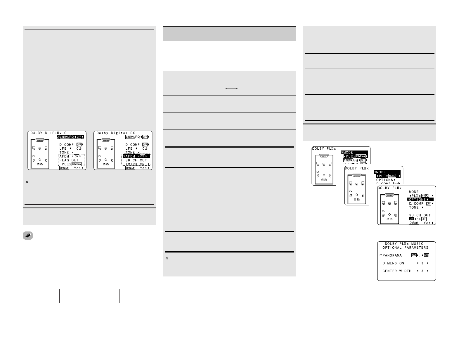
27
Basic Operation Basic Operation
AFDM (Auto Flag Detect Mode):
• ON:
When software including Dolby Digital EX or DTS-ES 6.1-
channel identification signals is played, 6.1-channel playback
is performed automatically. The surround mode is set
according to the program source being played. The “SB CH
OUT” parameter on the surround parameters screen cannot
be selected.
• OFF:
Not detected automatically. The surround mode can be
selected freely.
Example: When playing Dolby Digital software (with EX flag)
q When “AFDM” is “ON”, the “DOLBY DIGITAL + PL
II x
CINEMA” mode is set automatically.
w To play in the Dolby Digital EX mode, set “AFDM” to “OFF”
and select “MTRX ON” at “SB CH OUT”.
Some discs recorded in Dolby Digital EX do not include EX
flag. If the playing mode does not switch automatically
when the AFDM turns “ON” during playback, manually set
“SB CH OUT” to “PLII x Cinema” or “MTRX ON”.
Press ENTER or SURROUND PARAMETER.
7
• Select “Default Yes” and press
FF
to reset all the settings.
2 Dialog normalization function
This operates automatically when playing Dolby Digital sources.
This is a function for automatically correcting the standard signal
level for different program sources. The correction value can be
checked by pressing
<
STATUS
>
.
Offset -4dB
Dial.Norm
The numbers are the correction value when corrected
to the standard level.
Example: q Example: w
Selecting the Dolby Pro Logic
II
x (Pro Logic
II
)
mode
Press STANDARD to select “DOLBY PLII x”.
Play a program source.
DTS NEO:6DOLBY PLIIx
Press SURROUND PARAMETER.
It is possible to play analog input signals and digital input signals
(2-channels) in the surround mode.
This mode is optimal for playing program sources recorded in
Dolby Surround.
When “MUSIC” is selected:
Press
DD HH
to select the item, then press
FF GG
to
set.
Optional parameters can only be set in the MUSIC mode.
Select “OPTIONS”, then press
FF
.
Press ENTER to return to the previous screen.
PANORAMA:
This is effective when the surround effect seems weak.
DIMENSION:
This shifts the center of the sound field image to the front or
surround side. This compensates for when the sound field
image seems unbalanced. (0 to 6, default : 3)
CENTER WIDTH:
A natural expansion to the front can be achieved by adjusting
the center signal’s output balance between the center and
front channels. (0 to 7, default : 3)
Press ENTER or SURROUND PARAMETER.
Press
FF GG
to select the play mode.
1
2
3
4
CINEMA:
This mode is suited for playing movie sources recorded in
Dolby Surround and general sources recorded in stereo.
MUSIC:
This mode is suited for playing stereo music signals in the
surround mode. With music signals, the sound field
expansion differs according to the type of music, the
recording conditions (live/studio), etc.. Because of this, the
MUSIC mode offers a number of optional parameters for
further adjusting the sound field.
GAME:
This mode is optimum for games. The GAME mode can only
be used for 2-channel audio sources.
PL:
This mode is compatible with conventional Dolby Pro Logic
sources.
5
6
3
4
(When “OPTIONS” is selected)
5
hh
(When “MUSIC” is selected)
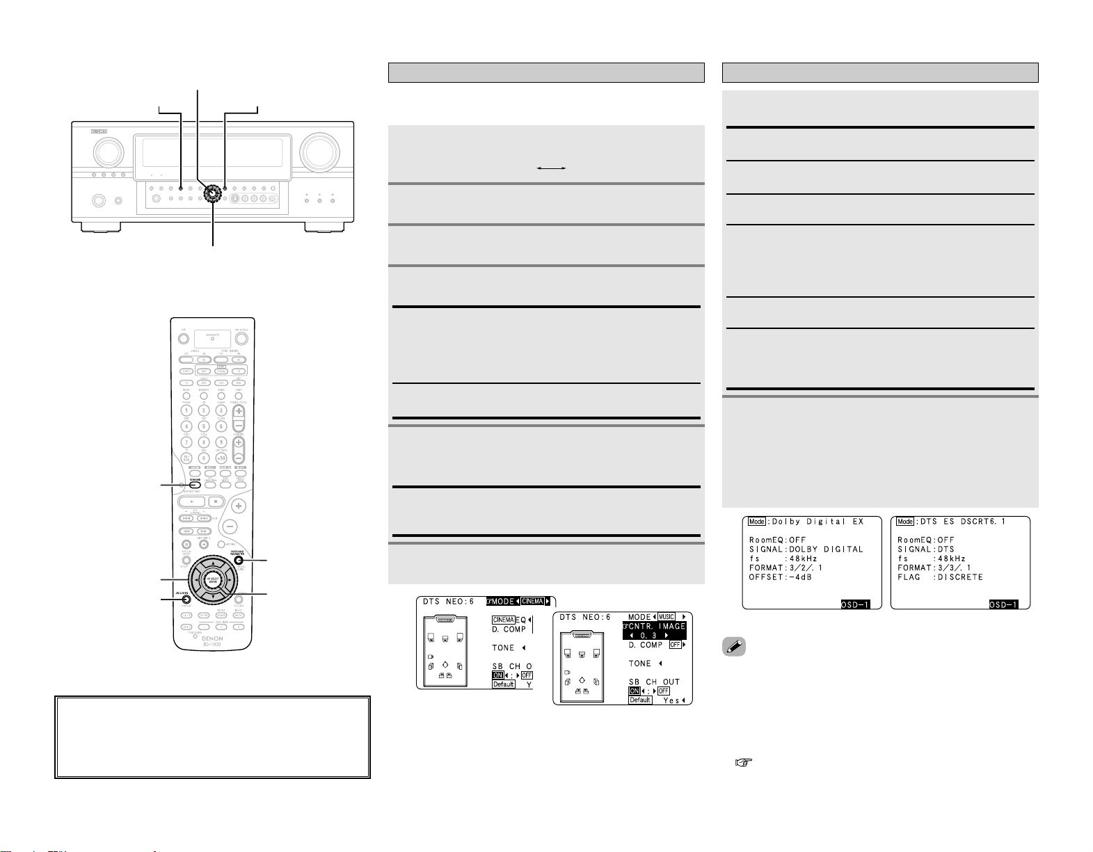
28
Basic Operation Basic Operation
FORMAT:
Displays the input signal’s number of channels (front /
surround / LFE on/off).
“SURROUND” is displayed for 2-channel signal sources
recorded in Dolby Surround.
OFFSET:
Displays the dialog normalization offset value.
FLAG:
“MATRIX” is displayed if the input signal has undergone
matrix processing, “DISCRETE” is displayed if the input signal
has undergone discrete processing.
SIGNAL:
Displays the type of input signal.
fs:
Displays the input signal’s sampling frequency.
Checking the input signals
Press [ON SCREEN].
1
Press [ON SCREEN] again.
• OSD-1 : Input signal
OSD-2 : HDMI monitor information
OSD-3 : Input/output settings
OSD-4 : Auto surround mode
OSD-5 ~ 7 : USER MODE 1 ~ 3
OSD-8 ~ 14 : Tuner preset stations
2
Room EQ:
Displays the type of equalizer currently set.
Example: Dolby Digital Example: DTS
1
• “OSD-1” “FLAG” is not displayed if there is no FLAG
identification signal in the input signal.
• OSD-2:
The monitor’s resolution is displayed when an HDMI monitor is
connected to the AVR-2807.
• OSD-4:
This is displayed when the auto surround mode is set to “ON”
( page 23) and the input mode is set to “AUTO”.
It is not displayed when the input mode is set to “ANALOG” or
“EXT. IN”.
About the button names in this explanation
<>: Buttons on the main unit
[]: Buttons on the remote control unit
Button name only :
Buttons on the main unit and remote control unit
D
H
F
G
STANDARD
ENTER
SURROUND
PARAMETER
SURROUND
PARAMETER
STANDARD
[ON SCREEN]
ENTER
D
H
F
G
Selecting the DTS NEO:6 mode
It is possible to play analog input signals and digital input signals
(2-channels) in the surround mode.
Press SURROUND PARAMETER.
Play a program source.
Press
FF GG
to select the play mode.
When “MUSIC” is selected:
Press
DD HH
to select “CNTR. IMAGE” , then press
FF GG
to set.
Press ENTER or SURROUND PARAMETER.
CNTR. IMAGE:
The expansion of the center channel can be adjusted. (0.0 to
1.0, default : 0.3)
2
3
4
5
6
Press STANDARD to select “DTS NEO:6”.
DTS NEO:6DOLBY PLIIx
1
CINEMA:
This mode is optimum for playing movies. Decoding is
performed with emphasis on separation performance to
achieve the same atmosphere with 2-channel sources as with
6.1-channel sources.
MUSIC:
This mode is suited mainly for playing music.
3
5
(When “MUSIC” is selected)
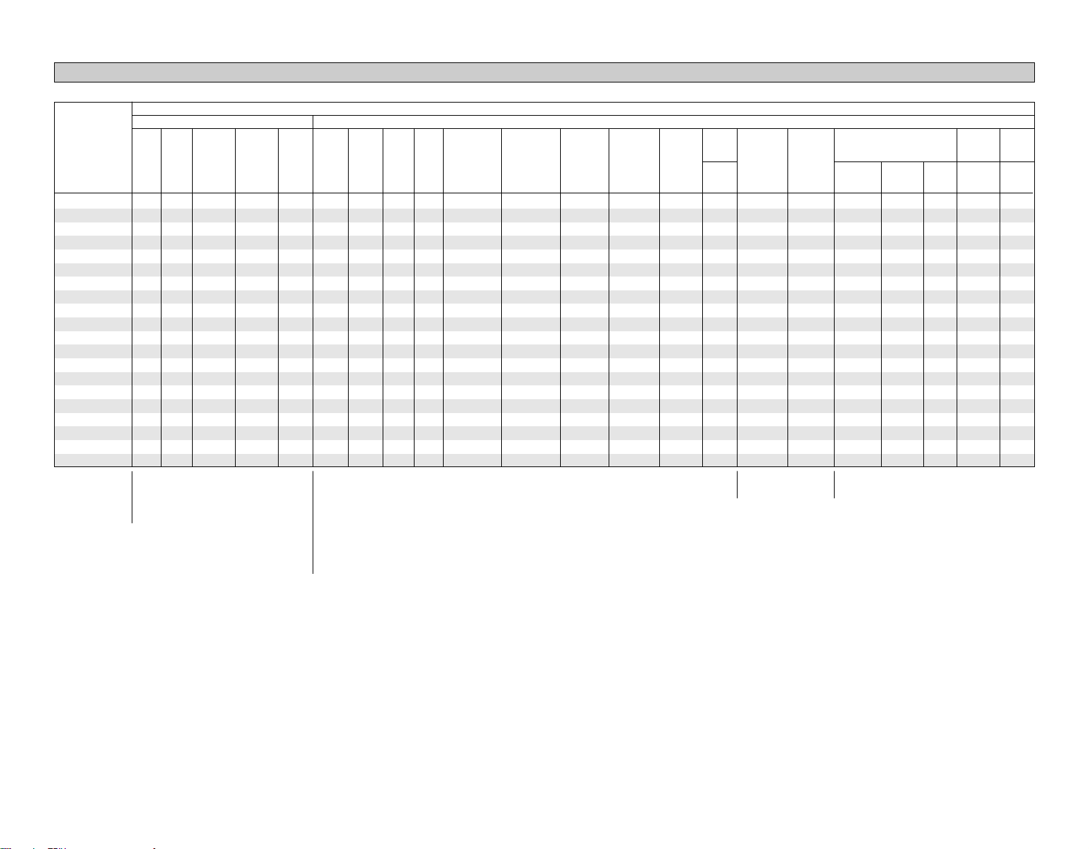
Surround Mode
29
Basic Operation Basic Operation
Surround modes and parameters
Signals and adjustability in the different modes
EE
EE
EE
EE
EE
EE
CC
(CINEMA)
CC
(CINEMA)
CC
(CINEMA)
EE
EE
EE
EE
EE
EE
EE
EE
EE
EE
EE
EE
EE
EE
EE
EE
CC
(OFF)
CC
(NOTE3)
CC
(NOTE4)
CC
(NOTE3)
CC
(OFF)
CC
(OFF)
EE
EE
EE
EE
EE
EE
EE
EE
EE
EE
EE
CC
(0 dB)
EE
CC
(0 dB)
CC
(0 dB)
CC
(0 dB)
CC
(0 dB)
CC
(0 dB)
CC
(0 dB)
CC
(0 dB)
CC
(0 dB)
CC
(NOTE1)
CC
(NOTE2)
CC
(0 dB)
CC
(0 dB)
CC
(0 dB)
CC
(0 dB)
CC
(0 dB)
CC
(0 dB)
EE
CC
EE
EE
CC
CC
CC
CC
CC
CC
CC
CC
CC
CC
CC
CC
CC
CC
CC
EE
EE
CC
(ON)
EE
EE
CC
(ON)
EE
EE
EE
EE
CC
(ON)
CC
(ON)
EE
EE
EE
EE
EE
EE
EE
EE
EE
CC
(0 dB)
CC
(0 dB)
CC
(0 dB)
EE
CC
(0 dB)
CC
(0 dB)
EE
EE
EE
CC
(0 dB)
CC
(0 dB)
CC
(0 dB)
CC
(0 dB)
CC
(0 dB)
CC
(0 dB)
CC
(0 dB)
CC
(0 dB)
CC
(0 dB)
CC
(0 dB)
CC
(0 dB)
CC
(OFF)
EE
CC
(OFF)
EE
EE
CC
(OFF)
CC
(OFF)
CC
(OFF)
CC
(OFF)
CC
(OFF)
CC
(OFF)
CC
(OFF)
CC
(OFF)
CC
(OFF)
CC
(OFF)
CC
(OFF)
CC
(OFF)
CC
(OFF)
CC
(OFF)
CC
(OFF)
BB
BB
BB
BB
BB
BB
BB
BB
BB
BB
BB
BB
BB
BB
BB
BB
BB
BB
BB
BB
EE
BB
EE
BB
BB
BB
BB
EE
BB
BB
BB
BB
BB
BB
BB
BB
BB
BB
BB
EE
EE
BB
EE
BB
BB
BB
BB
BB
BB
BB
BB
BB
BB
BB
BB
BB
BB
BB
BB
EE
CC
CC
CC
CC
CC
CC
CC
CC
CC
CC
CC
CC
CC
CC
CC
CC
CC
CC
CC
CC
SURROUND
L/R
Channel output Parameter (default values are shown in parentheses)
SUB-
WOOFER
D. COMP
*1
NIGHT
mode
LFE
*2
AFDM
*1
SB CH
OUT
TONE
CONTROL
CINEMA EQ. MODE
ROOM
SIZE
EE
BB
EE
BB
BB
BB
BB
BB
BB
BB
BB
BB
BB
BB
BB
BB
BB
BB
BB
EE
EE
EE
EE
EE
EE
EE
EE
EE
EE
EE
EE
EE
CC
(Medium)
CC
(Medium)
CC
(Medium)
CC
(Medium)
CC
(Medium)
CC
(Medium)
EE
EE
Dolby
Digital
EE
EE
EE
EE
EE
CC
(ON, 10)
EE
EE
EE
EE
EE
EE
CC
(10)
CC
(10)
CC
(10)
CC
(10)
CC
(10)
CC
(10)
EE
EE
FRONT
L/R
CENTER
SURROUND
BACK
L/R
CC
(OFF)
EE
CC
(OFF)
EE
EE
CC
(OFF)
CC
(OFF)
CC
(OFF)
CC
(OFF)
CC
(OFF)
EE
CC
(OFF)
CC
(OFF)
CC
(OFF)
CC
(OFF)
CC
(OFF)
CC
(OFF)
CC
(OFF)
CC
(OFF)
CC
(OFF)
EE
EE
EE
CC
EE
EE
EE
EE
EE
EE
EE
EE
EE
EE
EE
EE
EE
EE
EE
EE
EE
EE
EE
EE
EE
EE
EE
EE
CC
(0.3)
EE
EE
EE
EE
EE
EE
EE
EE
EE
EE
EE
EE
EE
EE
EE
EE
EE
CC
(3)
CC
(3)
EE
EE
EE
EE
EE
EE
EE
EE
EE
EE
EE
EE
EE
EE
EE
EE
EE
EE
CC
(3)
CC
(3)
EE
EE
EE
EE
EE
EE
EE
EE
EE
EE
EE
EE
CC
EE
EE
EE
EE
EE
EE
EE
EE
EE
EE
EE
EE
EE
EE
EE
EE
EE
EE
EE
EE
EE
EE
EE
EE
EE
EE
EE
EE
EE
EE
EE
EE
EE
EE
EE
EE
EE
CC
(30 msec)
EE
DELAY TIME
PANORAMA
SUBWOOFER
ON/OFF
DIMENSION
CENTER
WIDTH
CENTER
IMAGE
SW ATT
EE
EE
EE
EE
EE
EE
CC
(OFF)
CC
(OFF)
EE
EE
EE
EE
EE
EE
EE
EE
EE
EE
EE
EE
PRO LOGIC
II/IIx MUSIC MODE
only
NEO:6
MUSIC
MODE only
EXT. IN
only
EFFECT
LEVEL
CC
: Adjustable
EE
: Not adjustable
NOTE1 : BASS +6 dB, TREBLE 0 dB
NOTE2 : BASS +6 dB, TREBLE +4 dB
NOTE3 : This parameter is available when the “MODE” is set to “CINEMA”.
NOTE4 : This parameter is available when the “MODE” is set to “CINEMA” or “PL”.
*1:
When playing Dolby Digital and DTS signals.
*2:
When playing Dolby Digital, DTS, DVD-Audio and Super Audio CD.
CC
: Signal
EE
: No signal
CC
: Adjustable
EE
: Not adjustable
CC
: Signal
EE
: No signal
BB
:Turned on or off by speaker
configuration setting
PURE DIRECT, DIRECT
MULTI CH DIRECT
STEREO
EXT. IN
MULTI CH IN
WIDE SCREEN
DOLBY PRO LOGIC
II x
DOLBY PRO LOGIC
II
DTS NEO:6
DOLBY DIGITAL
DTS SURROUND
7CH STEREO
SUPER STADIUM
ROCK ARENA
JAZZ CLUB
CLASSIC CONCERT
MONO MOVIE
VIDEO GAME
MATRIX
VIRTUAL
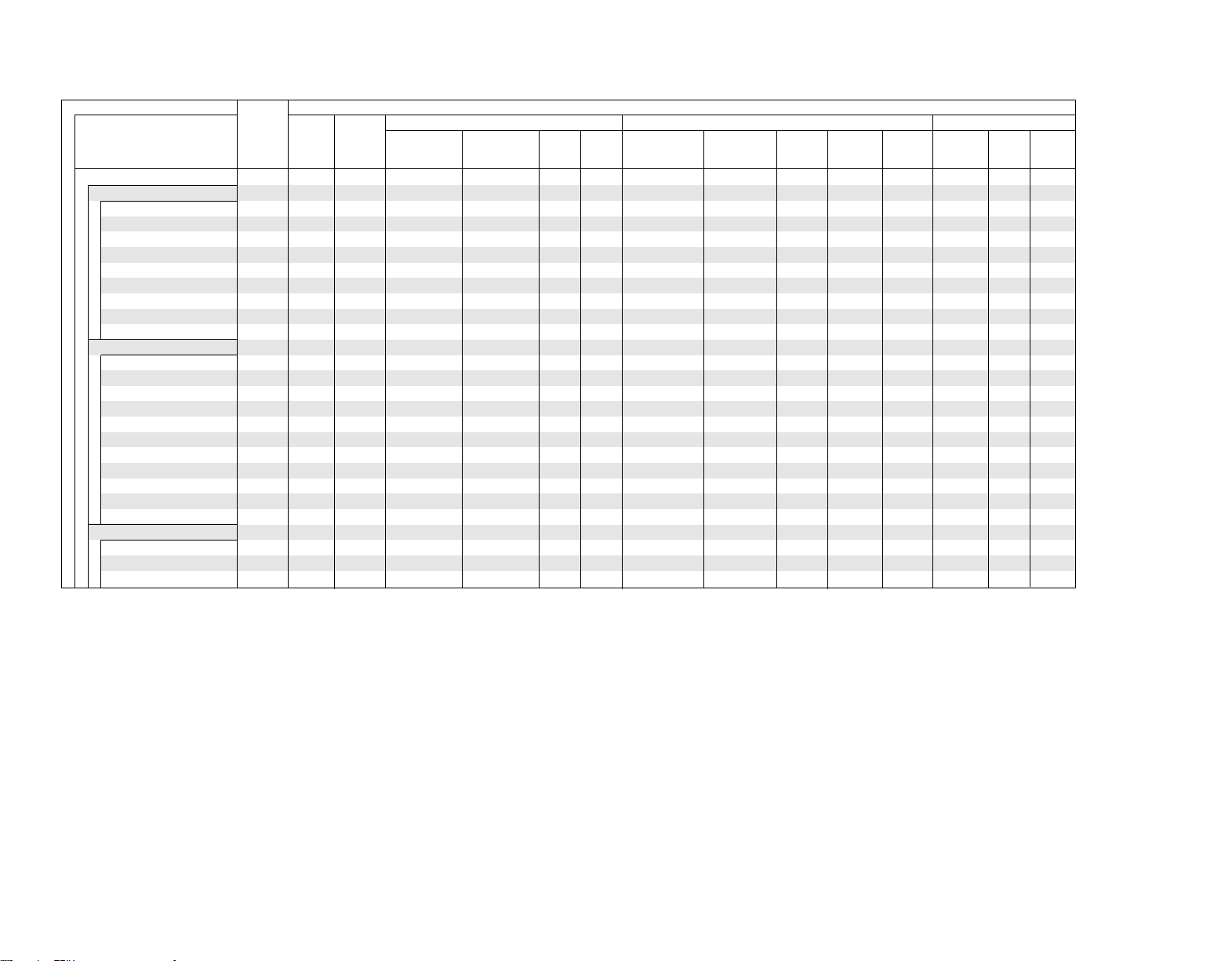
30
Basic Operation Basic Operation
2 Differences in surround mode names depending on the input signals
EE
EE
EE
EE
EE
EE
EE
EE
EE
EE
EE
EE
EE
EE
EE
EE
EE
EE
EE
EE
EE
EE
EE
EE
EE
EE
EE
EE
EE
EE
EE
EE
EE
EE
EE
EE
EE
EE
EE
EE
EE
EE
EE
4
CC
CC
EE
EE
EE
EE
EE
EE
EE
CC
CC
EE
EE
EE
EE
CC
CC
CC
CC
CC
CC
CC
EE
EE
EE
EE
EE
EE
EE
EE
EE
EE
CC
CC
EE
EE
EE
EE
4
CC
CC
CC
CC
CC
CC
EE
EE
EE
EE
EE
EE
EE
EE
EE
EE
EE
EE
CC
4
CC
CC
EE
EE
EE
EE
EE
EE
EE
EE
EE
EE
EE
EE
EE
EE
EE
EE
EE
EE
EE
CC
4
CC
CC
EE
EE
EE
EE
EE
EE
EE
EE
EE
EE
EE
EE
EE
EE
EE
EE
EE
EE
EE
CC
CC
4
BB
CC
EE
EE
EE
EE
EE
EE
EE
EE
EE
EE
EE
EE
EE
EE
EE
EE
EE
EE
EE
CC
4
CC
CC
EE
EE
EE
EE
EE
EE
EE
EE
EE
EE
EE
EE
EE
4
CC
CC
CC
EE
EE
EE
EE
EE
EE
EE
EE
EE
EE
EE
EE
EE
EE
EE
EE
EE
EE
4
EE
CC
CC
CC
EE
EE
EE
EE
EE
EE
EE
EE
EE
EE
EE
EE
EE
EE
EE
EE
EE
4
BB
CC
EE
CC
CC
CC
EE
EE
EE
EE
EE
EE
EE
EE
EE
EE
EE
EE
EE
EE
EE
EE
4
BB
EE
CC
EE
CC
CC
EE
EE
EE
EE
EE
EE
EE
EE
EE
EE
EE
EE
EE
EE
EE
EE
EE
EE
EE
EE
EE
EE
EE
EE
CC
CC
EE
EE
EE
EE
CC
CC
CC
CC
CC
CC
CC
EE
EE
EE
EE
EE
EE
EE
EE
EE
EE
CC
CC
EE
EE
EE
EE
CC
CC
CC
CC
CC
CC
CC
EE
EE
EE
*1
*1
*2
*1
*1
*1
*2
*1
*2
*1
Surround Mode
Button
Note
DTS ES DSCRT
(With Flag)
Input signals
DTS DOLBY DIGITAL
STANDARD
DTS SURROUND
DTS ES DSCRT6.1
DTS ES MTRX6.1
DTS SURROUND
DTS 96/24
DTS + PL
II x CINEMA
DTS + PL
II x MUSIC
DTS + NEO:6
DTS NEO:6 CINEMA
DTS NEO:6 MUSIC
DOLBY SURROUND
DOLBY DIGITAL EX
DOLBY DIGITAL
DOLBY DIGITAL+PL
II x CINEMA
DOLBY DIGITAL+PL
II x MUSIC
DOLBY PRO LOGIC
II x CINEMA
DOLBY PRO LOGIC
II x MUSIC
DOLBY PRO LOGIC
II x GAME
DOLBY PRO LOGIC
II CINEMA
DOLBY PRO LOGIC
II MUSIC
DOLBY PRO LOGIC
II GAME
DOLBY PRO LOGIC
MULTI CH IN
MULTI CH IN
MULTI IN + PL
II x CINEMA
MULTI IN + PL
II x MUSIC
ANALOG
LINEAR
PCM
DTS ES MTRX
(With Flag)
DTS
(5.1ch)
DTS
96/24
DOLBY DIGITAL EX
(With Flag)
DOLBY DIGITAL
EX
(With no Flag)
DOLBY
DIGITAL
(5.1ch)
DOLBY
DIGITAL
(3, 4, 5ch)
DOLBY
DIGITAL
(2ch)
DVD-AUDIO
DVD-Audio
(multi ch)
DVD-
Audio
(2ch)
176.4/
192kHz
4 : Mode selectable in default status
BB
: Mode fixed when AFDM is “ON”
CC
: Selectable mode
EE
: Non-selectable mode
NOTE :
*1: This mode is not available when the Surround Back speaker setup is set to “None”.
*2: This mode is not available when the Surround Back speaker setup is set to “1spkr” or “None”.

31
Basic Operation Basic Operation
Surround Mode
Button
Note
DTS ES DSCRT
(With Flag)
Input signals
DTS DOLBY DIGITAL
ANALOG
LINEAR
PCM
DTS ES MTRX
(With Flag)
DTS
(5.1ch)
DTS
96/24
DOLBY DIGITAL EX
(With Flag)
DOLBY DIGITAL
EX
(With no Flag)
DOLBY
DIGITAL
(5.1ch)
DOLBY
DIGITAL
(3, 4, 5ch)
DOLBY
DIGITAL
(2ch)
DVD-AUDIO
DVD-Audio
(multi ch)
DVD-
Audio
(2ch)
176.4/
192kHz
CC
EE
EE
EE
CC
EE
EE
EE
EE
EE
EE
EE
EE
EE
EE
EE
EE
EE
4
EE
CC
CC
CC
EE
CC
CC
CC
CC
CC
CC
CC
CC
CC
CC
CC
CC
CC
CC
CC
EE
EE
EE
CC
EE
EE
EE
EE
EE
EE
EE
EE
EE
EE
EE
EE
EE
4
CC
EE
EE
EE
CC
EE
EE
EE
CC
CC
CC
CC
CC
CC
CC
CC
CC
CC
CC
CC
EE
EE
EE
CC
EE
EE
EE
CC
CC
CC
CC
CC
CC
CC
CC
CC
CC
CC
CC
EE
EE
EE
CC
EE
EE
EE
CC
CC
CC
CC
CC
CC
CC
CC
CC
CC
CC
CC
EE
EE
EE
CC
EE
EE
EE
CC
CC
CC
CC
CC
CC
CC
CC
CC
CC
CC
CC
EE
EE
EE
CC
EE
EE
EE
CC
CC
CC
CC
CC
CC
CC
CC
CC
CC
CC
CC
EE
EE
EE
CC
EE
EE
EE
CC
CC
CC
CC
CC
CC
CC
CC
CC
CC
CC
CC
EE
EE
EE
CC
EE
EE
EE
CC
CC
CC
CC
CC
CC
CC
CC
CC
CC
CC
CC
EE
EE
EE
CC
EE
EE
EE
CC
CC
CC
CC
CC
CC
CC
CC
CC
CC
CC
CC
EE
EE
EE
CC
EE
EE
EE
CC
CC
CC
CC
CC
CC
CC
CC
CC
CC
4
CC
EE
EE
EE
CC
EE
EE
EE
CC
CC
CC
CC
CC
CC
CC
CC
CC
CC
4
*2
*1
*2
*1
*3
DIRECT
DIRECT
MULTI CH DIRECT
M DIRECT + PL
II
x CINEMA
M DIRECT + PL
II
x MUSIC
PURE DIRECT
PURE DIRECT
MULTI CH PURE DIRECT
M PURE D + PL
II x CINEMA
M PURE D + PL
II x MUSIC
DSP SIMULATION
7CH STEREO
WIDE SCREEN
SUPER STADIUM
ROCK ARENA
JAZZ CLUB
CLASSIC CONCERT
MONO MOVIE
VIDEO GAME
MATRIX
VIRTUAL
STEREO
CC
EE
EE
EE
CC
EE
EE
EE
CC
CC
CC
CC
CC
CC
CC
CC
CC
CC
CC
4 : Mode selectable in default status
CC
: Selectable mode
EE
: Non-selectable mode
NOTE :
*1: This mode is not available when the Surround Back speaker setup is set to “None”.
*2: This mode is not available when the Surround Back speaker setup is set to “1spkr” or “None”.
*3: If the Surround Back speaker setup is set to “None”, then “5CH STEREO” is displayed.
STEREO
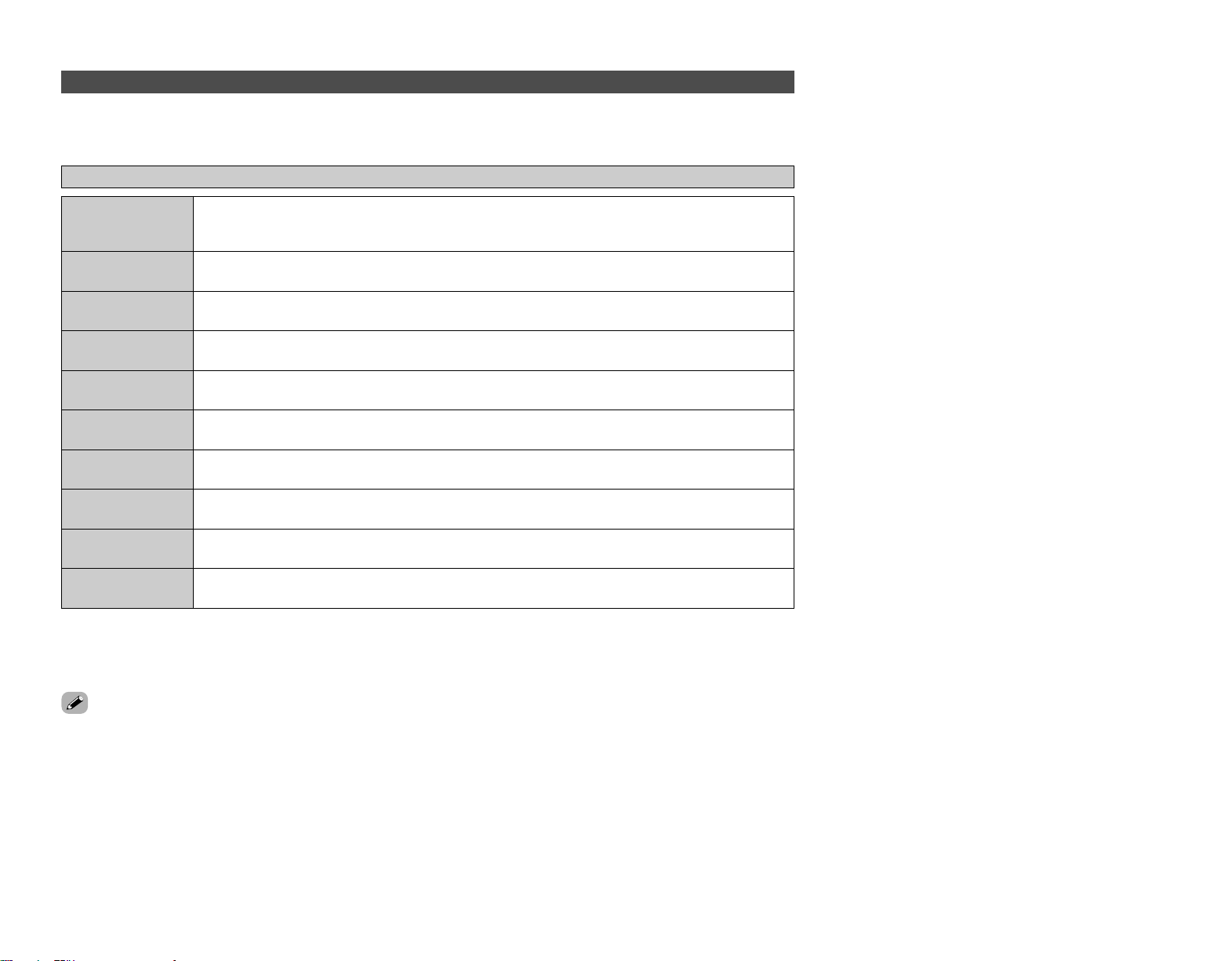
7CH STEREO
(NOTE 1)
32
Basic Operation Basic Operation
VIRTUAL
MATRIX
VIDEO GAME
MONO MOVIE
(NOTE 2)
CLASSIC CONCERT
JAZZ CLUB
ROCK ARENA
SUPER STADIUM
WIDE SCREEN
Using the DENON original surround modes
The AVR-2807 is equipped with a high performance digital signal processor (DSP) that uses digital signal processing to recreate sound
fields artificially. One of 10 surround modes can be selected according to the program source and parameters can be further adjusted
to achieve even more realistic sound fields.
Types of surround modes and their features
This mode recreates the atmosphere of watching a movie in a theater with a large screen. In this mode, all
sources are played in the 7.1-channel mode.
This mode recreates the atmosphere of watching a game of baseball, soccer or other sport in a stadium.
This mode recreates the atmosphere of a live concert in an arena.
This mode recreates the atmosphere of a live concert in a club with low ceilings, hard walls and the artist
just in front of you.
This mode provides a rich sense of presence for video games.
This mode recreates the atmosphere of a concert hall with rich reverberations.
This mode recreates the atmosphere of an expansive sound field for movie sources recorded in monaural.
This mode recreates music sources recorded in stereo with an enhanced sense of expansion.
This mode can be used to enjoy surround sound with only front speakers or when using headphones.
NOTE 1: “5CH STEREO” is displayed when “SB CH OUT” is set to “OFF”.
NOTE 2: When playing sources recorded in monaural, the sound will be one-sided if signals are only input to one channel (left or right),
so input signals to both channels. If you have a source component with only one audio output (monophonic camcorder, etc.)
obtain a “Y” adapter cable to split the mono output to two outputs, and connect to the L and R inputs.
• Depending on the program source being played, the effect may not be very noticeable. In this case, try other surround modes,
without worrying about their names, to create a sound field suited to your tastes.
This mode lets you enjoy stereo sound with 7 speakers. The front L (R) channel signals are played from the
surround and surround back L (R) channels and only the in-phase component of the L and R channels is
played on the center channel.
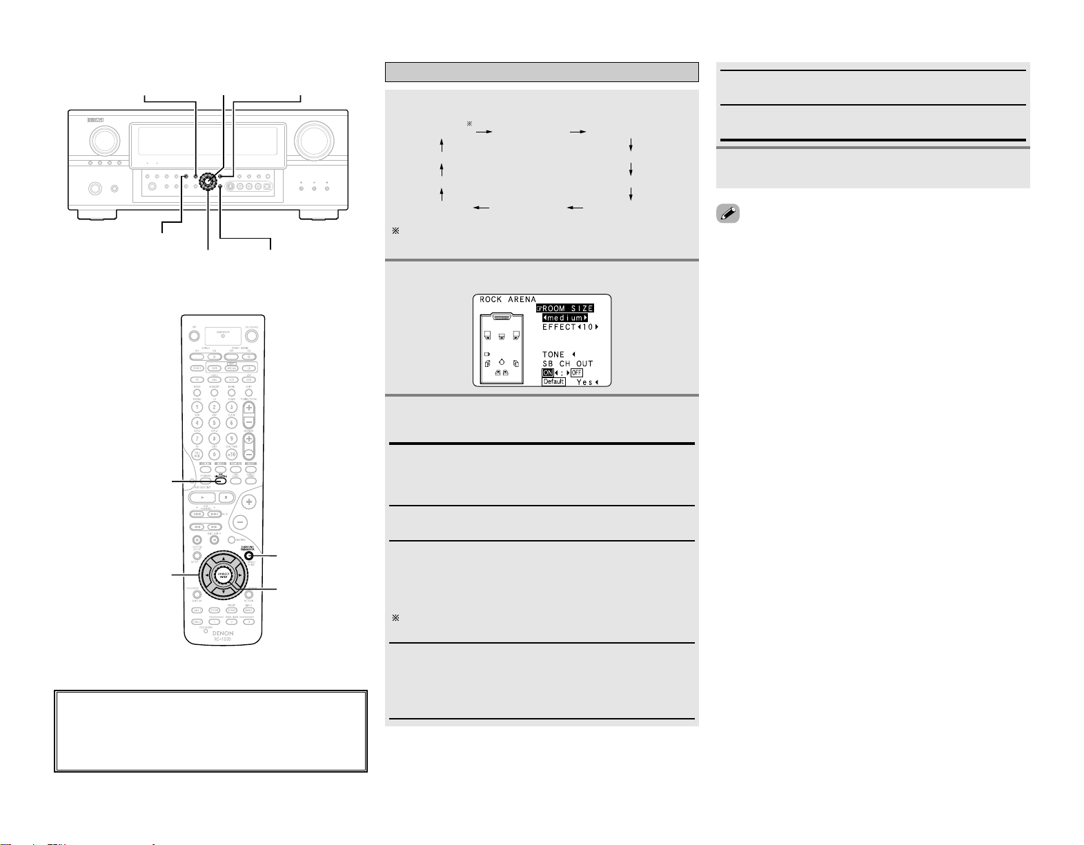
33
Basic Operation Basic Operation
• Select “Default Yes” and press
FF
to reset all the settings.
Press
DD HH
to select the item, then press
FF GG
to
set.
Press ENTER or SURROUND PARAMETER.
Selecting the DSP surround simulation
Press SURROUND PARAMETER.
Press [DSP SIMULATION].
7CH STEREO WIDE SCREEN SUPER STADIUM
JAZZ CLUB
ROCK ARENA
MATRIX
VIDEO GAME CLASSIC CONCERTMONO MOVIE
VIRTUAL
The 7CH STEREO mode can be selected directly by
pressing <7CH STEREO>.
1
2
3
4
EFFECT: (WIDE SCREEN mode only)
Effect signals with the multi-surround speaker effects are
played. When set to “OFF”, the SL/ SR channels are played
from the SBL/ SBR channels, respectively.
LEVEL: (WIDE SCREEN mode only)
Adjust the strength of effect signals “1” to “15”.
ROOM SIZE:
Adjust the imaginary size of the recreated sound field space.
(Does not express size of room in which played.)
There are 5 parameters: “small”, “med.s”, “medium”,
“med.l” and “large”.
SB CH OUT
• ON:
Surround back channel played.
• OFF:
Surround back channel not played.
This operation can also be performed using
<
SURROUND
BACK
>
.
EFFECT LEVEL:
Adjust the strength of the surround effect.
DELAY TIME: (MATRIX mode only)
Adjust the delay time between “0 ms” and “300 ms”.
About the button names in this explanation
<>: Buttons on the main unit
[]: Buttons on the remote control unit
Button name only :
Buttons on the main unit and remote control unit
D
H
F
G
<SURROUND BACK>
<7CH STEREO>
DSP
SIMULATION
SURROUND
PARAMETER
ENTER
SURROUND
PARAMETER
ENTER
D
H
F
G
DSP SIMULATION
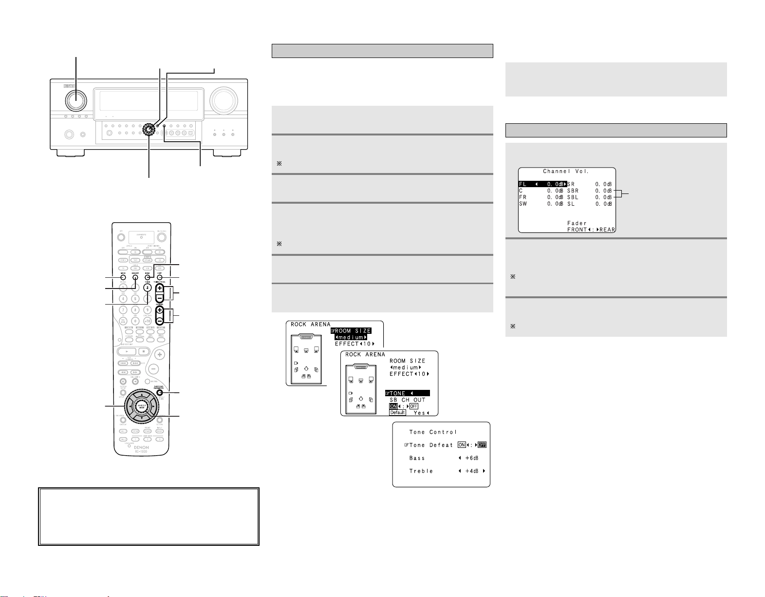
34
Basic Operation Basic Operation
Press ENTER.
Press ENTER or SURROUND PARAMETER.
Press
GG
to select “OFF”.
Press
DD HH
to select “Bass” or “Treble”, then press
FF GG
to set the level.
Can be adjusted within the range of –6 dB to +6 dB.
3
4
5
6
1
2
2 When you do not want to adjust the tone
Either press
<
TONE DEFEAT
>
or set “Tone Defeat”
to “ON” at step 3 in “Adjusting the tone”.
3
Adjusting the speaker volume
Press CH SEL/ENTER.
Press
DD HH
or CH SEL/ENTER to select the
speaker.
The settable speaker switches each time this button is
pressed.
Press
FF GG
to adjust the volume.
Can be adjusted within the range of –12 dB to +12 dB.
1
2
3
“SB” when surround back
speaker set to “1spkr”.
Not displayed when
“None” set.
Setting the tone control
Adjust the bass and treble to suit your tastes.
Press SURROUND PARAMETER.
Press
DD HH
to select “TONE”, then press
FF
.
In the direct mode, “TONE” cannot be selected.
2 Adjusting the tone
1
2
About the button names in this explanation
<>: Buttons on the main unit
[]: Buttons on the remote control unit
Button name only :
Buttons on the main unit and remote control unit
D
H
F
G
<TONE DEFEAT>
SURROUND
PARAMETER
CH SEL/
ENTER
<FUNCTION>
SURROUND
PARAMETER
CH SEL/ENTER
D
H
F
G
[SHIFT]
[BAND]
[MODE]
[MEMORY]
[TUNER]
[TUNING]
[CHANNEL]
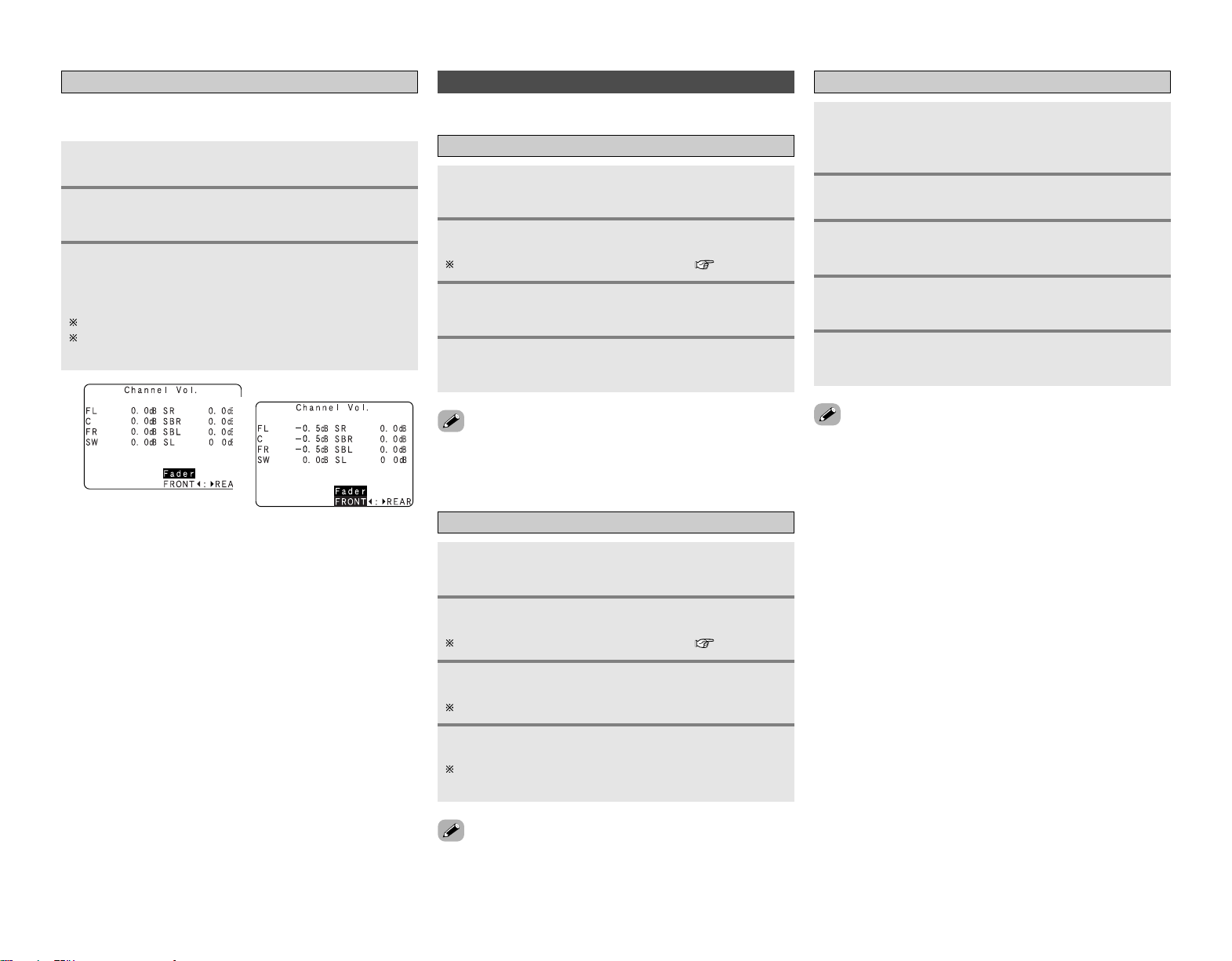
35
Basic Operation Basic Operation
Either turn
<
FUNCTION
>
or press [TUNER] to
select “TUNER”.
Auto tuning
Manual tuning
• When the manual tuning mode is set, FM stereo broadcasts are
received in monaural and the “STEREO” indicator turns off.
Press [MODE] to set the auto tuning mode.
• The “AUTO” indicator lights.
Press [TUNING].
• Automatic searching begins.
• If tuning does not stop at the desired station, use to the
“Manual tuning” operation.
Listening to the radio
Check that the remote control unit is set to “AMP”.
Either turn
<
FUNCTION
>
or press [TUNER] to
select “TUNER”.
Press [MODE] to set the manual tuning mode.
Check that the display’s “AUTO” indicator turns off.
Press [BAND] to select “AM”, “FM” or “XM”.
When listening to the XM Satellite Radio ( page 36, 37).
Press [BAND] to select “AM”, “FM” or “XM”.
When listening to the XM Satellite Radio ( page 36, 37).
Press [TUNING] to tune in the desired station.
The frequency changes continuously when the button is
held in.
1
2
3
4
1
2
3
4
Use the “Auto tuning” or “Manual tuning”
operation to tune in the station to be preset in the
memory.
Press [MEMORY].
Press [CHANNEL] to select the desired preset
channel (1 to 8).
Preset memory
Press [SHIFT] to select the desired memory block
(A to G).
Press [MEMORY] again.
• Store the station in the preset memory.
1
2
3
4
5
•To preset other channels, repeat steps 2 to 5.
A total of 56 broadcast stations can be preset — 8 stations
(channels 1 to 8) in each of blocks A to G.
• The memory block can also be selected by pressing [SHIFT].
Using the fader function
With this function, the volume of all the front side speakers or all
the rear side speakers can be adjusted (attenuated) at once.
Press CH SEL/ENTER.
Press
DD HH
or CH SEL/ENTER to select “Fader”.
Press
FF
to attenuate the volume of all the front
side speakers,
GG
to attenuate the volume of all the
rear side speakers.
The fader function does not affect the subwoofer.
It is possible to adjust so that the volume of the speaker
whose volume is the lowest is –12 dB.
1
2
3
2
3
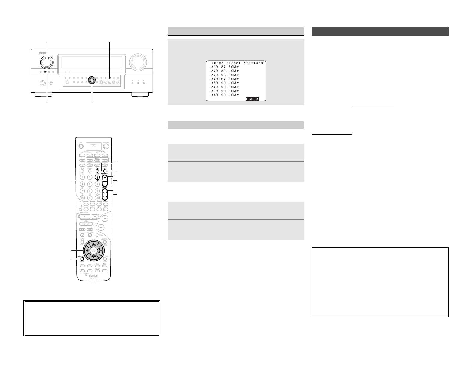
36
Basic Operation Basic Operation
Recalling preset stations
2 Remote control unit
Press [SHIFT] to select the memory block.
Press [CHANNEL] to select the desired preset
channel.
2 Main unit
Press
<
TUNING PRESET
>
.
Turn
<
FUNCTION
>
and select the desired preset
channel.
1
2
1
2
Press [ON SCREEN] repeatedly until the “Tuner
Preset Stations” screen appears on the OSD.
Checking the preset stations
About the button names in this explanation
<>: Buttons on the main unit
[]: Buttons on the remote control unit
Button name only :
Buttons on the main unit and remote control unit
D
H
F
G
<TUNING PRESET>
<STATUS>
<FUNCTION>
D
H
F
G
[SHIFT]
[BAND]
[ON SCREEN]
[TUNER]
[TUNING]
[CHANNEL]
XM Satellite Radio
2 Introducing XM Satellite Radio
There’s a world of audio listening pleasure beyond AM and FM.
XM Satellite Radio. Select from over 150 channels of music,
news, sports, comedy, talk, and entertainment. Coast-to-coast
coverage. Digital quality sound. With all music channels 100%
commercial free.
Questions?: Visit www.xmradio.com.
AVR-2807 is the XM Ready® receiver. You can receive XM
Satellite Radio® by connecting to the XM Connect-and-Play
TM
(sold separately) and subscribing the XM service.
2 How to Subscribe
Listeners can subscribe by visiting XM on the Web at
www.xmradio.com or by calling XM’s Listener Care at (800) 967-
2346.
Customers should have their Radio ID and credit card ready. The
Radio ID can be found by selecting channel 0 on the radio.
2 A Warning Against Reverse Engineering
It is prohibited to copy, decompile, disassemble, reverse
engineer, or manipulate any technology incorporated in receivers
compatible with the XM Satellite Radio system.
Furthermore, the AMBE® voice compression software included
in this product is protected by intellectual property rights
including patent rights, copyrights, and trade secrets of Digital
Voice Systems, Inc. The user of this or any other software
contained in an XM Radio is explicitly prohibited from attempting
to copy, decompile, reverse engineer, or disassemble the
object code, or in any other way convert the object code into
human-readable form. The software is licensed solely for use
within this product.
Hardware and required basic monthly subscription sold
separately. Premium Channel available at additional monthly
cost.
Installation costs and other fees and taxes, including a one-
time activation fee may apply. Subscription fee is consumer
only.
All fees and programming subject to change. Subscriptions
subject to Customer Agreement available at xmradio.com.
Only available in the 48 contiguous United States. ©2005 XM
Satellite Radio Inc. All rights reserved. All other trademarks
are the property of their respective owners.
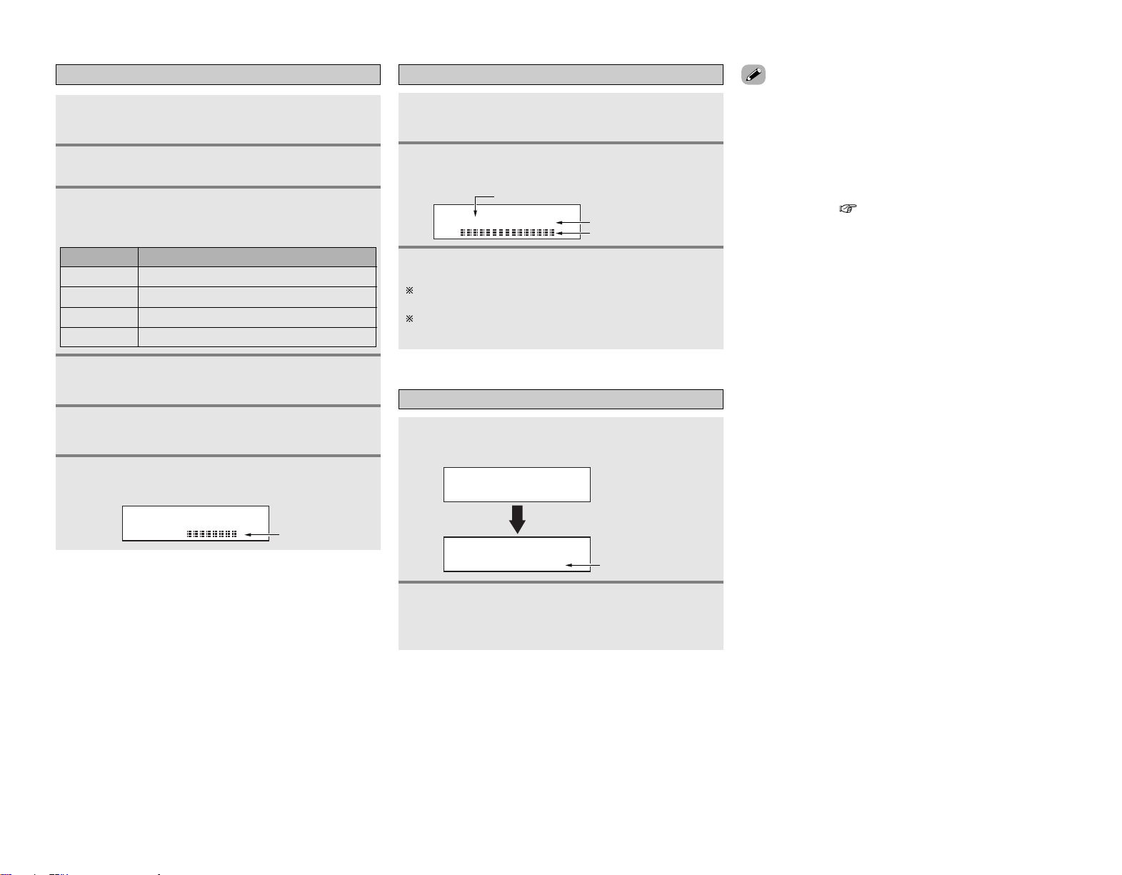
37
Basic Operation Basic Operation
Checking the XM signal strength and Radio ID
XM000 RADIO ID
Radio ID
Either turn
<
FUNCTION
>
or press [TUNER] to
select “TUNER”.
Press
<
STATUS
>
until “SIGNAL” is displayed.
• The display changes as shown below according to the
receiving condition.
Press [BAND] to select “XM”.
1
2
3
Adjust the antenna location until
“SIGNAL:GOOD” is displayed.
4
Press
<
STATUS
>
until the XM channel
(ex.XM001) is displayed.
5
Press [TUNING –] to select channel 0 (XM000).
6
Category search
CATEGORY SEARCH
XM040 DeepTrks
CAT: Rock
XM040 DeepTrks
Channel Category
• “LOADING” is displayed while receiving the channel or
information.
• “UPDATING” is displayed while updating encryption code.
• When the selected channel is not available, “XM– – –” is
displayed.
• Information on the artist name, song title, category and signal
level can be checked using
<
STATUS
>
.
• The XM Satellite Radio channels can be preset in the same way
as AM/FM band ( page 35).
3
Channel selection
XM040 DeepTrks
Song title/Artist name
Channel name
Channel number
Press [TUNING] to reach the desired channel.
The channel changes continuously when you press and hold
[TUNING].
When the artist name and song title are received, they are
displayed.
3
Either turn
<
FUNCTION
>
or press [TUNER] to
select “TUNER”.
Press [BAND] to select “XM”.
1
2
Press
FF GG
to select the category, and press
DD HH
to select the channel within the selected category.
2
Press
FF GG
in the XM mode.
• The current category name is displayed.
1
ConditionDisplay
NO
GOOD Signal strength is good
MARGINAL Signal strength is marginal
WEAK Signal strength is poor
Loss of the signal
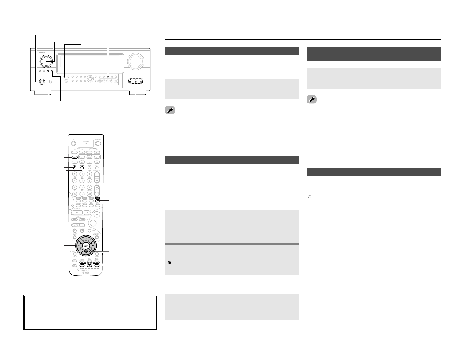
38
Advanced Operation
Advanced Operation
The night mode can be set when playing Dolby Digital sources.
The dialogues are easier to hear at night and when listening with
the volume low.
Press NIGHT.
•The “NIGHT” indicator lights.
Night mode
• Canceling night mode:
Press NIGHT again.
• When the night mode is set to “ON”, the “D.COMP” surround
parameter can not be selected.
2 Calling the settings out
Press USER MODE at which the settings you want to
call out are stored.
• The selected user mode display lights.
User mode function
The AVR-2807 is equipped with a function for storing the
selected input source, the auto surround mode and input mode
in the memory and selecting these settings when you want to
use them.
The following are stored in the memory:
qq
Currently set input source
ww
Currently set surround mode
ee
Currently set input mode
2 Storing the settings in the memory
Press and hold USER MODE.
Press and hold in until the selected user mode indicator
lights.
1
2
Press
<
VIDEO SELECT
>
, turn
<
FUNCTION
>
until the
desired image appears on the display.
Combining the currently playing sound with
the desired image (VIDEO SELECT function)
•To cancel, press
<
VIDEO SELECT
>
and turn
<
FUNCTION
>
to select
“SOURCE”.
• The video source selected with the video select function is
stored in the memory for the different input sources.
• It is not possible to select HDMI input signals.
• When playing HDMI video input signals, the analog video signal
of another function cannot be selected for the HDMI video
output.
About the button names in this explanation
<>: Buttons on the main unit
[]: Buttons on the remote control unit
Button name only :
Buttons on the main unit and remote control unit
<FUNCTION> <STATUS>
NIGHT<ON/STANDBY>
<ZONE2/REC SELECT>
USER MODE<VIDEO SELECT>
[ZONE2]
[MODE]
[MEMORY]
NIGHT
USER MODE
CH SEL/ENTER
D
H
F
G
The surround mode last selected and the input mode setting are
stored individually for the different input sources.
The surround parameters, tone control settings and playback
level balance for the different output channels are memorized
for each surround mode.
Personal memory plus function
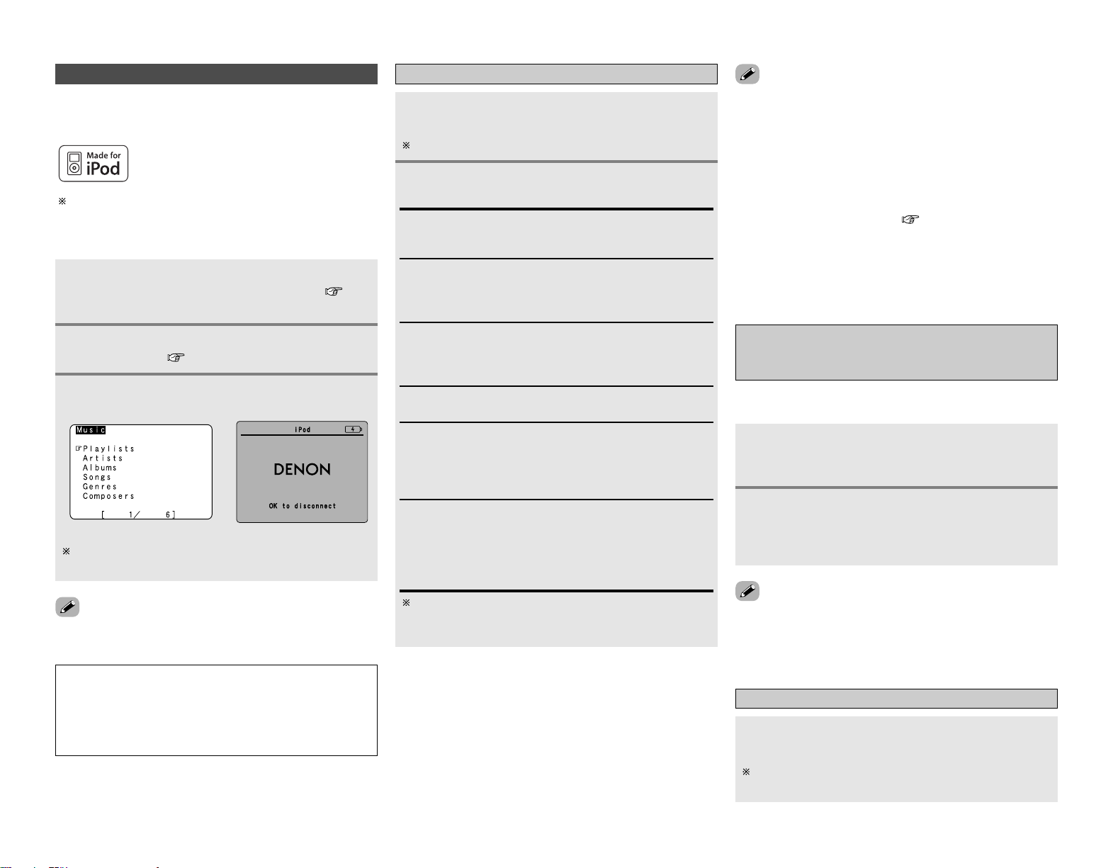
Advanced Operation Advanced Operation
39
Playing the iPod
®
iPod is a trademark of Apple Computer, Inc.,
registered in the U.S. and other countries.
If the screens above are not displayed, the iPod may not be
properly connected. Check the connections and settings.
(iPod screen)
With the iPod, non-copyrighted contents and contents that
may be legally reproduced or played may be reproduced and
played by individuals for their personal use. Violating
copyrights is prohibited by law.
NOTE:
• DENON will accept no responsibility whatsoever for loss or
damage of data on an iPod occurring when the iPod is used
connected to the AVR-2807.
• Some of the functions may not operate, depending on the
type of iPod and the software version.
Listening to music
Press
DD HH
to select the music file, then press
ENTER or
GG
.
Press
FF
to return to the music menu screen.
Press ENTER or
GG
.
• Playback starts.
Manual search:
Press and hold in
DD HH
during playback.
•
DD
: Fast reverse
•
HH
: Fast forward
Track search:
Press
DD HH
during playback.
•
DD
: Move to beginning of previous track
•
HH
: Move to beginning of next track
Repeat play:
Press [MODE].
The mode switches as follows each time [MODE] is pressed.
• RPT One: Single track repeat
• RPT All : All track repeat
Shuffle play:
Press [MEMORY].
The mode switches as follows each time [MEMORY] is
pressed.
• SFL Songs : Single track shuffle
• SFL Albums: Album shuffle
Pause:
Press ENTER during playback.
Press again to resume.
Stop:
Press ENTER for at least 2 seconds during playback.
The mode switches between the Browse mode and the
Remote mode if [MODE] is pressed for at least 2 seconds.
In the Remote mode, only
DD HH FF GG
and ENTER can be used.
1
2
•When
<
STATUS
>
is pressed during playback, the front panel
display switches between the title name, artist name and
album name.
• Depending on the iPod’s software version, it may not be
possible to operate the iPod from the AVR-2807. Use the latest
version of the software. Information on the latest version of the
software can be obtained on the Apple Computer website.
• If you do not want the on screen display to be displayed while
playing the iPod, set “Function/Mode Status” at “Setting the
On Screen Display” to “OFF” ( page 52).
•With the AVR-2807 it is possible to display folder names and file
names on the screen like titles. The AVR-2807 can display up to
64 characters, consisting of numbers, capital letters and small
letters. A “?” mark is displayed in place of non-compatible
characters.
Viewing still pictures and videos
(only for iPods equipped with the slideshow /
video function)
Press [MODE] for at least 2 seconds to switch
from the Browse mode to the Remote mode.
• “Remote iPod” is displayed on the AVR-2807’s display.
Watching the iPod’s screen, press
DD HH
to select
“Photos” or “Video”, then press ENTER or
GG
.
• The iPod’s photo and video data are displayed on the
monitor.
Use this procedure to view photo and video data stored on the
iPod on a monitor.
Disconnecting the iPod
Press
<
ON/STANDBY
>
and set the AVR-2807’s
power to the standby mode.
The iPod can be disconnected after switching to a function
other than the one to which the iPod input is assigned.
1
2
Connect the AVR-2807 and iPod using the
DENON original Control Dock for iPod ( page
21).
1
Use FUNCTION to select the function assigned in
step 2.
3
Assign the input terminal at “Setting the iPod
Assignment” ( page 47).
2
• The optional standard Control Dock for iPod is DENON ASD-1R
sold separately.
The music recorded on the iPod can be played when using a
DENON original Control Dock for iPod (ASD-1R). The iPod can be
controlled using the buttons on the main unit and the remote
•To output photo or video data recorded on the iPod to the
monitor, the iPod’s “TV Out” setting (under “Video Settings”)
must be set to “ON”.
For details, refer to the iPod’s operating instructions.

Advanced Operation Advanced Operation
40
•When the outputs of the ZONE2 output terminals are wired and connected to power amplifiers
installed in other rooms, different sources can be played in rooms other than the MAIN ZONE in
which this unit and the playback devices are installed. (Refer to ZONE2 on the diagram below.)
• Settings can be made at “Power Amp Assign” in the “System Setup Menu” so that the same
source as the ZONE2 output terminals can be played from the speakers connected to the ZONE2
speaker terminals ( page 22).
• When a sold separately room-to-room remote control unit (DENON RC-616, 617 or 618) is wired
and connected between the MAIN ZONE and ZONE2, the remote-controllable devices in the
MAIN ZONE can be controlled from ZONE2 using the remote control unit.
To control playback devices other than the ones above, either use that device’s remote control
unit or preset a separately sold programmable remote control unit.
Multi zone music entertainment system
• For instructions on installation and operation of separately sold devices, refer to the devices’
operating instructions.
Multi-zone playback using the ZONE2 output terminals
2 When using the power amplifier as the MAIN ZONE output
The AVR-2807 is equipped with ZONE2 output terminals for which the volume is fixed output level
and composite video output terminals as the ZONE2 output terminals.
[System configuration and connections example]
• Using this AVR-2807 external amplifier as the ZONE2.
RC-617
C
FL
FL
FR
FR
SL
SW
SR
SB
R
SB
L
B
RC-616
MAIN ZONE 7.1-channel systems
ZONE2
Monitor
DVD player
AVR-2807
ZONE2 Audio out
(Fixed out)
ZONE2
Video out
Premain Amplifier
Input
Monitor
Multi-zone playback using the SPEAKER terminals
2 When using the SURROUND BACK amplifier as the ZONE2 output
When the surround back’s power amplifier is assigned to the ZONE2 output channel at “Power
Amp Assign” in the “System Setup Menu”, the surround back speaker terminals can be used as
the ZONE2 speaker out terminals ( page 54).
[System configuration and connections example]
• Using this AVR-2807 internal amplifier as the ZONE2.
C
FL
FL
FR
FR
SL
SW
SR
RC-617
RC-616
MAIN ZONE 5.1-channel systems
ZONE2
Monitor
DVD player
AVR-2807
Multi-zone speaker out
ZONE2 Video out
Input
Monitor
system remote control
unit RC-1030
Programmable
remote control unit
ZONE2 Audio out (Fixed out)
ZONE2 Audio out (Fixed out)
system remote control
unit RC-1030
Programmable
remote control unit
: Multi source audio signal cable
: Multi source video signal cable
: Room-to room remote control
system (separately sold) control line
: Speaker cable
Refer to “Connections” ( page 21, 22).
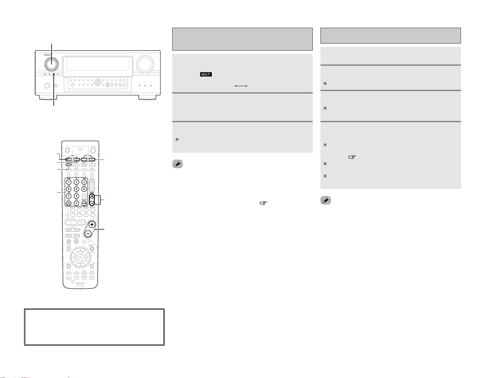
41
Advanced Operation Advanced Operation
With “ZONE2 SOURCE” displayed, turn
<
FUNCTION
>
to select the source you want to
output appears on the display.
Outputting a program source to amplifier,
etc., in the ZONE2 room
(ZONE2 SELECT mode)
• The signals of the source selected in the ZONE2 mode are also
output from the VCR-1, VCR-2 and CDR/TAPE recording output
terminals.
• Digital signals are not output from the ZONE2 audio output
terminals.
• About the MULTI ZONE connections ( page 40).
Press
<
ZONE2/REC SELECT
>
to display the
“ZONE2 SOURCE” on the display.
• The “ ” indicator lights.
Start playing the source to be output.
For operating instructions, refer to the manuals of the
respective components.
RECOUT
ZONE2
Remote control unit operations during multi-
source playback
Press [ZONE2] to select “ZONE2”.
Press [ZONE2 ON] to turn on the zone power.
Press [ZONE2 OFF] to turn off the zone power.
Select the input source you wish to output.
When the function is set to TUNER, the preset channel can
be selected using [CHANNEL].
The volume of the outputs of the different zones
can be adjusted with [VOLUME].
The ZONE2 volume can be adjusted only when “ZONE2” is
selected at “Power Amp Assign” in the “System Setup
Menu” ( page 54).
Default volume setting:
ZONE2 : –40 dB
The zone volume can be adjusted within the range of –70 to
18 dB.
1
2
3
4
1
2
3
<FUNCTION>
<ZONE2/REC SELECT>
[ZONE2 ON]
[ZONE2 OFF]
[FUNCTION]
(ZONE2)
[VOLUME]
[ZONE1 (MAIN) ON/OFF]
[CHANNEL]
[ZONE2]
About the button names in this explanation
<>: Buttons on the main unit
[]: Buttons on the remote control unit
Button name only :
Buttons on the main unit and remote control unit
• When using ZONE2, it is possible to turn the power for the
MAIN ZONE (main zone) only on or off by pressing [ZONE1
(MAIN) ON/OFF].
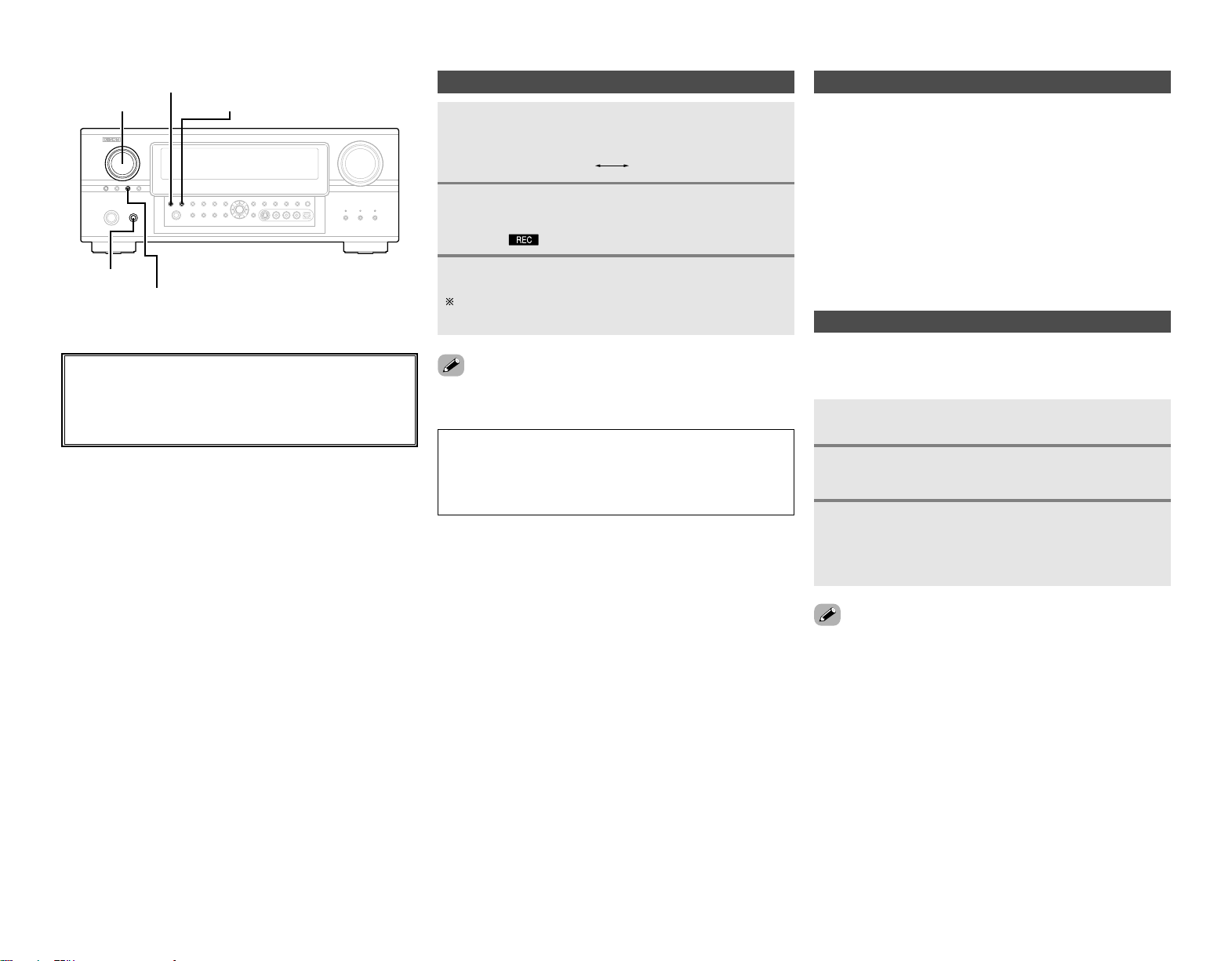
42
2 Last function memory
The various settings set when the AVR-2807’s power is switched
to standby are stored in the memory. When the power is turned
back on, the settings made when the power was switched to
standby are recalled.
About the memory functions
2 Backup memory
The various settings are stored in the memory for about 1 week,
even when the power is turned off or the power cord is
unplugged.
Switch off the unit using
<
POWER
>
.
Hold the following
<
PURE DIRECT
>
and
<
NIGHT
>
,
and press
<
POWER
>
.
• If step 3 does not work, start over from step 1.
• If the microprocessor has been reset, all the settings are reset
to the default values.
Initialization of the microprocessor (Reset)
Use the procedure described below to reset the microprocessor
if the display is abnormal or if the buttons on the main unit or the
remote control unit do not operate.
Check that the entire display is blinking with an
interval of about 1 second, and release your
fingers from the 2 buttons.
• The microprocessor will be initialized.
1
2
3
Advanced Operation Advanced Operation
About the button names in this explanation
<>: Buttons on the main unit
[]: Buttons on the remote control unit
Button name only :
Buttons on the main unit and remote control unit
<FUNCTION>
<NIGHT>
<ZONE2/REC SELECT>
<POWER>
<PURE DIRECT>
Recording (audio and/or video)
Press
<
ZONE2/REC SELECT
>
until “RECOUT”
appears on the display.
Use
<
FUNCTION
>
to select the source to be
recorded (audio and/or video).
• The “ ” indicator lights.
Record (the audio or video signals).
For operations, see the operating instructions of the device
from which you are recording (audio or video signals).
•To cancel, press
<
ZONE2/REC SELECT
>
and set the function to
“ZONE2”.
1
2
3
NOTE:
•When the REC OUT mode is selected, [ZONE2] and
[FUNCTION] (ZONE2) cannot be operated.
• Digital signals are not output from the analog REC OUT,
OPTICAL 3 OUT and OPTICAL 4 OUT terminals.
RECOUT
ZONE2

PageDefault settingsItems
43
PageDefault settingsItems
Advanced Setup – Part 1
Advanced Setup – Part 1
1. Auto Setup/Room EQ
1 Auto Setup
Room EQ
Setup
2
Direct Mode
Setup
4
3
Mic Input
Select
–
All, Room EQ = OFF
OFF
Mic
9 ~ 12
60
60
61
System setup items and default values
2. Speaker Setup
1
3
Speaker
Config.
Channel
Level
Front Sp.
Large
Center Sp. Surround Sp.Subwoofer
Small SmallYes
Surround
L & R
Center
Front
L & R
Subwoofer
10 ft (3.0 m)12 ft (3.6 m)12 ft (3.6 m) 12 ft (3.6 m)
Front
L
Front
R
Center Surround R Subwoofer
0 dB 0 dB 0 dB 0 dB 0 dB
Surround Back
Sp.
Small / 2spkrs
4
Distance
Surround L
0 dB
Crossover
Frequency
5
80 Hz
56, 57
2
Subwoofer
Setup
LFE
57
57, 58
58, 59
59
Surround
Back
10 ft (3.0 m)
Surround
Back R
0 dB
Surround
Back L
0 dB
This unit performs an analysis of the speaker system and
measures the acoustic characteristics of your room to permit
an appropriate automatic setting.
Set the Room Equalizer setting with “All” or “Assign” for
each surround mode.
Set the ON/OFF setting of Room Equalizer, in the case of the
surround mode is in “Direct” or “Pure Direct”.
Sets whether the setup microphone is connected to the pin
jack (V. AUX L channel) or mIni jack (SETUP MIC).
Automatically set the output component and properties for
the various channels according to the combination of
speakers to be actually used for surround playback.
This parameter is for optimizing the timing with which the
audio signals are produced from the speakers and
subwoofer according to the listening position.
Set the volume of the various speakers so that the sound
output from the speakers and the subwoofer seems to have
the same volume level.
Select the method of playback of the subwoofer for playing
the low bass signals.
Set the frequency (Hz) below which the bass sound of the
various speakers is to be output from the subwoofer.
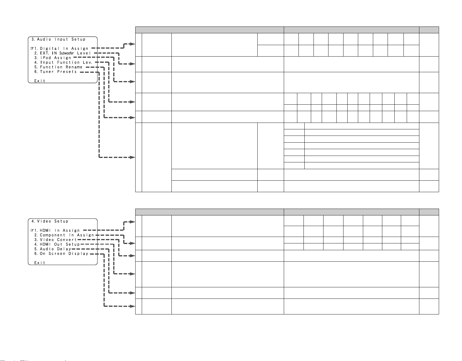
PageDefault settingsItems
44
PageDefault settingsItems
Advanced Setup – Part 1 Advanced Setup – Part 1
4. Video Setup
2
Component
In Assign
HDMI In
Assign
DVD VDP TV
1
50
3
Video
Convert
ON
50
49, 50
DBS VCR-1 VCR-2 V.AUX
1-RCA NONE 2-RCA 3-RCA NONE NONE NONE
Audio Delay5
0 ms
51
On Screen
Display
6
Function/Mode = ON
Master Volume = ON
Mode = Mode 1
52
DVD VDP TV DBS VCR-1 VCR-2 V.AUX
NONE
NONE NONE NONE
NONE
NONE
NONE
4
HDMI Out
Setup
Convert = ON
i/p Convert = ON
Color Space = Y Cb Cr
RGB Mode = Normal
51
3. Audio Input Setup
47
Digital In
Assign
Input
source
Digital
Inputs
CD DVD VDP TV DBS VCR-1 VCR-2
COAX 1 COAX 2 OPT 1 OFF OPT 2 OPT 3 OFF
1
CDR /
TAPE
OPT 4
V.AUX
OPT 5
2
EXT. IN
Subwoofer
Level
SW Level = +15 dB
48
Input
Function Lev.
TUNER PHONO CD
CDR /
TAPE
DVD VDP TV
0 dB 0 dB 0 dB 0 dB 0 dB 0 dB 0 dB
4
VCR-2
0 dB
DBS VCR-1
0 dB 0 dB
V.AUX
0 dB
5
Function
Rename
48
6
Tuner
Presets
A1 ~ A8
B1 ~ B8
C1 ~ C8
D1 ~ D8
E1 ~ E8
87.5/89.1/98.1/107.9/90.1/90.1/90.1/90.1 MHz
520/600/1000/1400/1500/1710 kHz, 90.1/90.1 MHz
90.1 MHz
90.1 MHz
90.1 MHz
Auto Preset
Memory
F1 ~ F8
G1 ~ G8
90.1 MHz
90.1 MHz
Preset Skip
Preset
Name
48
All preset channels = ON
49
–
49
47
TUNER PHONO CD
CDR /
TAPE
DVD VDP TV VCR-2DBS VCR-1 V.AUX
iPod Assign
It is possible to assign the DENON original Dock’s audio
and/or video signals to any input terminals on the AVR-2807
and play them.
iPod Function = OFF
473
This assigns the digital input terminals for the
different input sources.
Sets the playback level of the analog signal that was input to
the EXT. IN subwoofer terminal.
Up to 56 FM stations can be preset
automatically.
The playback level is corrected individually for the different
input sources.
The name of the input function that is displayed can be
changed.
Preset channels that are not used often can
be skipped.
The preset channels can be given the names
you want.
The HDMI input terminals are assigned for the different
input sources.
Select the HDMI audio signal playback method.
This assigns the component video input terminals for the
different input sources.
This sets whether or not to use the video conversion
function.
Set whether or not to up-convert from analog video signals
to HDMI. When this function is used, the format of the
signal output from the HDMI terminal can be set.
Adjust the time delay between the video and audio signals.
Set whether or not to display the on screen display for
indications other than the menu screens.
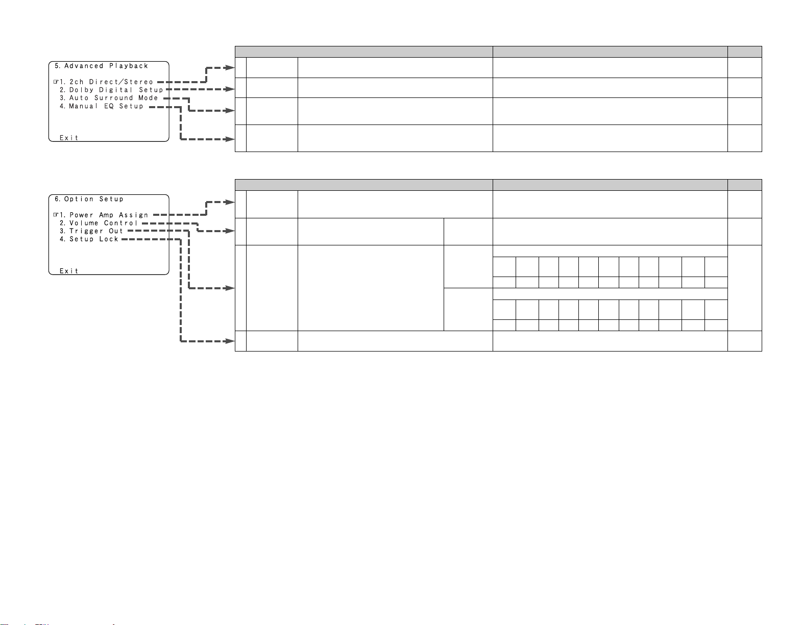
Items Default settings Page
45
PageDefault settingsItems
Advanced Setup – Part 1 Advanced Setup – Part 1
5. Advanced Playback
1
2
2ch
Direct/Stereo
Auto
Surround
Mode
3
Dolby Digital
Setup
Basic
OFF
Auto Surround Mode = ON
52
53
53
4
Manual EQ
Setup
All Channels and Frequency = 0 dB
53, 54
6. Option Setup
1
Power Amp
Assign
54
S. Back
56
2
Trigger Out3
Volume
Control
55
Setup Lock
55
Vol.Limit = OFF
P. On Lev. = LAST
Mute Lev. = FULL
Trigger Out
1
ZONE = MAIN, All Surround Modes = ON
Setup Lock = OFF
Main
4
TUNER PHONO CD
CDR /
TAPE
DVD VDP TV
VCR-2DBS VCR-1 V.AUX
OFF OFF OFF OFF ON ON ON ONON ON ON
Trigger Out
2
ZONE = 2
TUNER PHONO CD
CDR /
TAPE
DVD
VDP TV
VCR-2
DBS VCR-1
V.AUX
ON ON ON ON ON ON ON ONON ON ON
Make the 2-channel direct mode and stereo mode speaker
settings.
Turn the audio compression on or off when down-mixing
Dolby Digital signals.
Set whether or not to store the surround mode last played
for the input signal.
Adjust the tone of the various speakers while listening to the
playback signals.
To suit your preference, a surround back channel’s power
amplifier can be assigned to the front channel (“Front A” or
“Front B”) for bi-amp playback, ZONE2.
This sets the volume level of output.
Use the DC12V output of the AVR-2807’s
two trigger out jacks in association with the
various input sources and surround modes.
This sets whether or not to lock the system setup settings
so that they cannot be changed.
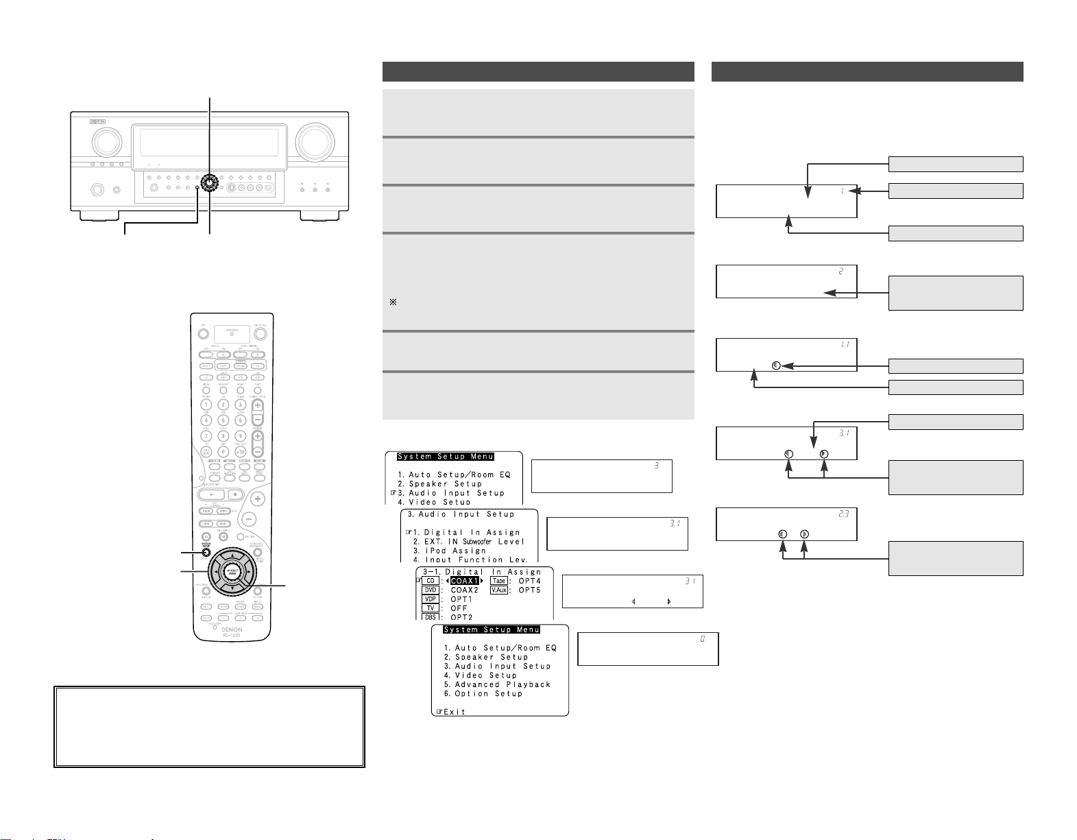
46
Advanced Setup – Part 1 Advanced Setup – Part 1
Navigating through the System Setup Menu
Press SYSTEM SETUP.
• The “System Setup Menu” appears.
Press
DD HH
again to select the item you want to set,
then press ENTER.
Press
DD HH
to select the item you want to set, then
press ENTER.
Press ENTER and set a new item.
Press SYSTEM SETUP to return to the “System
Setup Menu” or the main menu.
To change the setting:
Press
DD HH
to select the item you want to change,
then press
FF GG
to change the setting.
Select “Default Yes”, then press
FF
to reset to the default
setting.
1
2
3
4
5
6
Audio In Setup
*System Setup
[ On screen display ] [ Display ]
Digital In
*Audio In Setup
CD : COAX1
*Digital In
Exit
*System Setup
2
3
4
6
In addition to the easily understandable on screen display, the
AVR-2807 is also equipped with displays for checking the
settings. Use this when making settings and operating.
Below are some examples of typical displays.
About the display
[ Display ]
Auto Set/RoomEQ
*System Setup
Display title
Menu number
Submenu title
Currently selected line
Speaker Setup
*System Setup
Press
DD HH
to select
the menu.
Press
FF
to select.
Press
FF GG
to change the
setting.
Start
*Auto Setup
CD : COAX1
*Digital In
Meters : Feet
*Distance
Current setting
Press
FF GG
to select one or
the other.
About the button names in this explanation
<>: Buttons on the main unit
[]: Buttons on the remote control unit
Button name only :
Buttons on the main unit and remote control unit
ENTER
SYSTEM SETUP
D
H
F
G
ENTER
D
H
F
G
SYSTEM SETUP
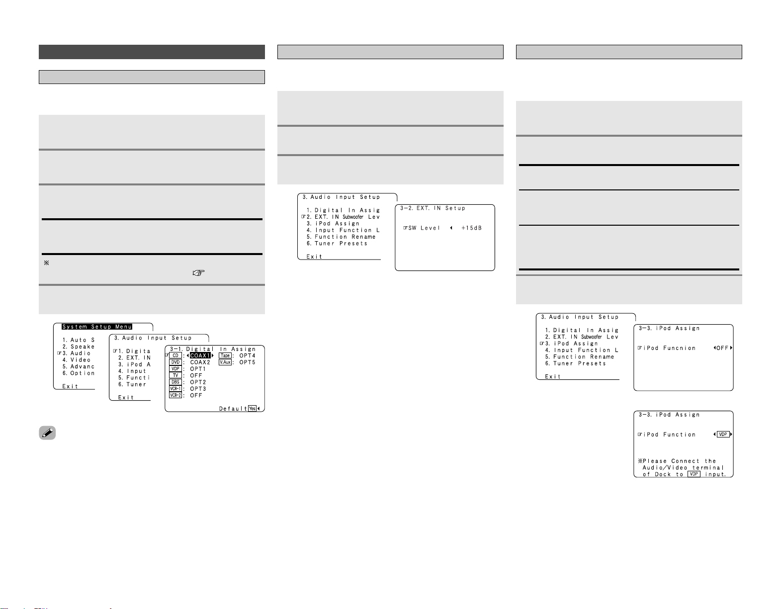
47
Press
FF GG
to set.
Advanced Setup – Part 1 Advanced Setup – Part 1
Audio Input Setup
Setting the Digital In Assignment
Press
DD HH
to select “Audio Input Setup”, then
press ENTER.
Press
DD HH
to select “Digital In Assign”, then press
ENTER.
Press ENTER.
Press
DD HH
to select the input source, then press
FF
GG
to set.
• “PHONO” and “TUNER” cannot be selected on the “Digital In
Assign” screen.
• It is not possible to make the “Digital In Assign” settings for
the function assigned at “iPod Assign”.
3
2
1
COAX1, COAX2, OPT1, OPT2, OPT3, OPT4, OPT5:
Assign the different terminals according to the devices
connected to the AVR-2807’s input terminals.
4
1
2
3
This assigns the digital input terminals for the different input
sources.
Setting the EXT. IN Subwoofer Level
Press
DD HH
to select “EXT. IN Subwoofer Level”,
then press ENTER.
Press
FF GG
to set.
Press ENTER.
1
2
3
1
2
Sets the playback level of the analog signal that was input to the
EXT. IN subwoofer terminal.
Setting the iPod Assignment
It is possible to assign the DENON original Dock’s audio and
video signals to any input terminals on the AVR-2807 and play
them.
1
Press
DD HH
to select “iPod Assign”, then press
ENTER.
OFF:
This is the factory default setting.
CD, CDR/TAPE:
When using a DENON original Dock, it is possible to connect
with the audio input terminal of the assigned function.
DVD, VDP, DBS, TV, VCR-1, VCR-2, V.Aux:
When using a DENON original Dock, it is possible to connect
with the audio and video input terminals of the assigned
function.
1
2
2
Press ENTER.
3
The HDMI input terminal is displayed when it is assigned to
the input source at “HDMI In Assign” ( page 49, 50).
(When “VDP” is selected)
hh

48
Advanced Setup – Part 1 Advanced Setup – Part 1
Setting the Input Function Level
Press
DD HH
to select “Input Function Lev.”, then
press ENTER.
• After completing this setting, check that the playback levels for
the different sources are the same.
1
Press
DD HH
to select the input source, then press
FF
GG
to set.
The volume can be adjusted within the range –12 dB to +12
dB.
2
Press ENTER.
3
1
2
Setting the Function Rename
Press
DD HH
to select “Function Rename”, then
press ENTER.
Press
DD HH
to select the input function, then press
FF GG
to set.
Press
FF GG
to move the cursor (
22
) to the desired
position, then press
DD HH
to select the character.
Up to 8 characters can be input.
The characters that can be input are shown below.
AB C D E F G H I J K L M N O P Q R S T U V W X Y Z
a b c d e f g h i j k l m n o p q r s t u v w x y z 0 1 2 3 4
5 6 7 8 9
! ” # % & ’ ( )
*
+ , – . / : ; < = > ? @ [ \ ] (space)
Repeat step 3 to input the input source name.
To set the input function name back to how it was:
q Press
FF GG
to highlight the input function name, then
press
DD HH
.
w Press
DD HH
to select “Default Yes”, then press
FF
.
Once all the characters have been input, press
ENTER.
1
2
3
4
5
1
2
The playback level is corrected individually for the different input
sources.
The name of the input function that is displayed can be changed.
Setting the Tuner Presets
2 Auto Preset Memory
Up to 56 FM stations can be preset automatically.
Press
DD HH
to select “Tuner Presets”, then press
ENTER.
Press
DD HH
to select “Auto Preset Memory”, then
press ENTER.
Press
FF
to select “Yes”.
• “Search” blinks on the screen and searching begins.
• “Completed” appears once searching is completed.
• If an FM station cannot be preset automatically due to poor
reception, use the “Manual tuning” operation ( page 35) to
tune in the station, then preset it using the manual “Preset
memory” operation ( page 35).
1
2
3
1
2
3
3
4

49
Advanced Setup – Part 1 Advanced Setup – Part 1
2 Preset Skip
Preset channels that are not used often can be skipped.
Press
DD HH
to select “Preset Skip”, then press
ENTER.
Press
FF GG
to select the preset memory block.
Press
DD HH
to select the preset channel, then press
FF GG
to set.
2 Preset Name
The preset channels can be given the names you want. (Except
the XM channels.)
Press
DD HH
to select “Preset Name”, then press
ENTER.
Press ENTER.
Press
DD HH
to select the preset channel, then press
FF GG
to set.
Repeat steps 2 and 3.
AB C D E F G H I J K L M N O P Q R S T U V W X Y
Z a b c d e f g h i j k l m n o p q r s t u v w x y z 0 1 2
3 4 5 6 7 8 9
! ” # % & ’ ( )
*
+ , – . / : ; < = > ? @ [ \ ] (space)
Once all the characters have been input, press
ENTER.
1
2
3
ON, OFF:
Select “OFF” to skip the preset channel, “ON” if you do not
want to skip.
When
HH
is pressed at the very bottom of the screen, then
the next preset memory block appears.
5
4
1
2
1
2
5
Press
FF GG
to move the cursor (
22
) to the desired
position, then press
DD HH
to select the character.
Up to 8 characters can be input.
The characters that can be input are shown below.
3
Repeat step 3 to input the preset channel name.
To set the preset channel name back to how it was:
q Press
FF GG
to highlight the preset channel, then press
DD
HH
.
w Press
DD HH
to select “Default Yes”, then press
FF
.
4
Press ENTER.
6
Video Setup
Setting the HDMI In Assignment
Press
DD HH
to select “Video Setup”, then press
ENTER.
Press
DD HH
to select “Audio”, then press
FF GG
to
select where to output the audio signals.
Press
DD HH
to select “HDMI In Assign”, then press
ENTER.
TV:
Output the TV connected to the AVR-2807.
AMP:
Output the speakers connected to the AVR-2807.
Press ENTER.
1
2
4
Press
DD HH
to select the input source, then press
FF
GG
to set.
3
HDMI1, HDMI2:
Assign the HDMI input signal to “HDMI1” (or “HDMI2”).
The HDMI input terminals are assigned for the different input
sources.
Select the HDMI audio signal playback method.
If no audio signal is included in the input signal:
Press
DD HH
to select the input source, then press
FF
GG
to set.
5
EXT. IN, ANALOG:
If there is no HDMI audio signal, the signal automatically
switches to the input from the set terminal.
6
3
1
2
3
4
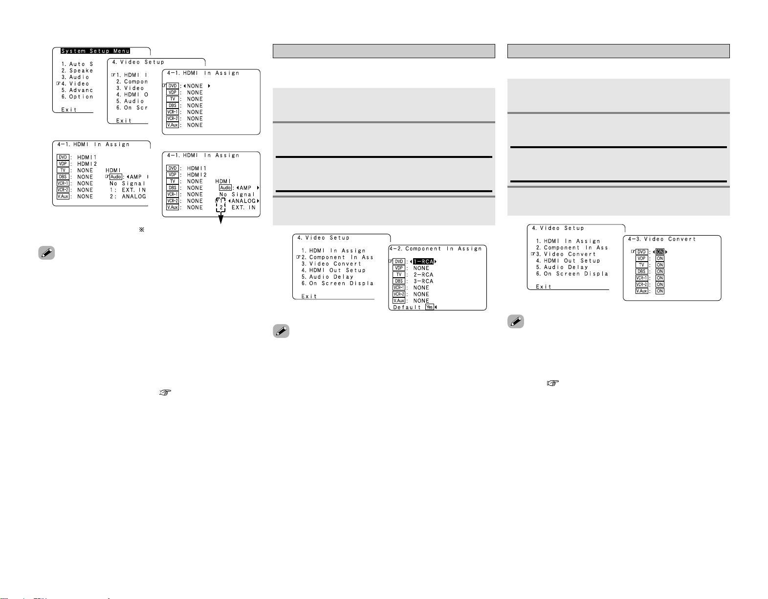
50
Advanced Setup – Part 1 Advanced Setup – Part 1
• If a monitor is connected with an HDMI cable but the monitor
is not compatible with HDMI audio signal playback, only the
video signals are output to the monitor from the AVR-2807.
• Audio signals input from the analog and digital terminals are not
output to the TV.
•With HDMI, the video and audio signals are transferred
simultaneously. When HDMI is assigned to an input source, the
digital audio input assignment switches to HDMI along with the
video input.
When this setting is made for input sources to which a digital
audio input (COAXIAL or OPTICAL) is previously assigned, the
digital audio assignment is set to HDMI.
In this case, reassign the digital input using the procedure
described at “Digital In Assign” ( page 47).
• It is not possible to make the “HDMI In Assign” settings for the
function assigned at “iPod Assign”.
Setting the Component In Assignment
This assigns the component video input terminals for the
different input sources.
Press
DD HH
to select “Component In Assign”, then
press ENTER.
1
2
3
4
5
Compatible with HDMI1 and HDMI2.
1
Press ENTER.
• Signals input to the component video input terminal are output
simultaneously from component video monitor output
terminals 1 and 2.
• It is not possible to make the “Component In Assign” settings
for the function assigned at “iPod Assign”.
3
Press
DD HH
to select the input source, then press
FF
GG
to set.
2
1-RCA, 2-RCA, 3-RCA:
Assign the “1-RCA” “2-RCA” or “3-RCA” input terminal to
the input function.
1
2
• If the resolution of the input component video signal is
something other than 480i/576i, down-conversion from the
component video signal to S-Video or video signals is not
possible. If you do not want to use the component video output
terminal, connect the player to the S-Video or video input
terminal ( page 14, 15).
• When a non-standard video signal from a game machine or
some other source is input, the video conversion function
might not operate. If this happens, please set the conversion
mode to “OFF”.
• When the video conversion function has been used,
information such as that of text broadcasts which has been
added to the video signal might not be output. If this happens,
please set the conversion mode to “OFF”.
Setting the Video Convert
Press
DD HH
to select “Video Convert”, then press
ENTER.
Press
DD HH
to select the input source, then press
FF
GG
to set.
ON, OFF:
Select “ON” to use the video conversion function, “OFF” if
you do not want to use it.
Press ENTER.
This sets whether or not to use the video conversion function.
1
2
3
1
2

51
Advanced Setup – Part 1 Advanced Setup – Part 1
Setting the HDMI Out Setup
Set whether or not to up-convert from analog video signals to
HDMI. When this function is used, the format of the signal
output from the HDMI terminal can be set.
Press
DD HH
to select “HDMI Out Setup”, then
press ENTER.
Press
DD HH
to select the item, then press
FF GG
to
set.
1
2
Press ENTER.
Analog to HDMI Convert:
• ON:
Setting for converting analog video signals into HDMI signals.
• OFF:
Setting for not converting analog video signals into HDMI
signals.
i/p Convert:
• ON:
When the video input signal is a video, S-Video or 480i/576i
component video signal, the resolution is converted to
480p/576p and the signal is output from the HDMI monitor
output terminal.
• OFF:
The video input signal is output as such from the HDMI
monitor output terminal without being converted.
Color Space:
• Y Cb Cr:
The Y Cb Cr format video signals is output via the HDMI
output terminal.
• RGB:
The RGB format video signals is output via the HDMI output
terminal.
RGB Mode Setup:
• Normal:
Signals are output via the HDMI output terminal with a digital
RGB video range (data range) of 16 (black) to 235 (white).
• Enhanced:
Signals are output via the HDMI output connector with a
digital RGB video range (data range) of 0 (black) to 255 (white).
•When the HDMI terminals are connected, the black may seem
to stand out, depending on the TV or the monitor. In this case,
set this to “Enhanced”.
• When “Y Cb Cr” is selected under “Color Space”, “RGB Mode
Setup” will have no effect.
• When “OFF” is selected under “i/p Convert”, the signal is
output with the same resolution as input from the video, S-
Video and component video terminals.
The OSD, however, is output with a resolution of 480i, so use
a monitor compatible with this resolution.
•“i/p Convert”, “Color Space” and “RGB Mode Setup” are only
displayed when “Analog to HDMI Convert” is set to “ON”.
• When connecting to an HDCP compatible monitor equipped
with DVI-D terminal using an HDMI/DVI-D converter cable, the
signals are output in RGB format, regardless of the “Color
Space” setting.
•To view the on screen display using an HDMI monitor, set
“Analog to HDMI Convert” at “HDMI Out Setup” to “ON”
(default).
Setting the Audio Delay
Adjust the time delay between the video and audio signals.
Press
DD HH
to select “Audio Delay”, then press
ENTER.
Press
FF GG
to set.
Press ENTER.
1
2
3
0 ms ~ 200 ms:
Adjust the time delay.
With a movie source, for example, adjust so that the
movement of the actors’ lips is synchronized with the
sound.
1
2
1
2
• By default, this menu is not displayed when no digital signals
are being input.
•To make this setting for the component video signal, select the
delay time and turn the on screen display off, then check that
the timing of the component video and audio match.
• The audio delay setting does not apply when playing in the EXT.
IN mode or in the analog input direct mode or stereo mode
(Front speaker setting “Large”, TONE DEFEAT “ON” and
Room EQ “OFF”).
3
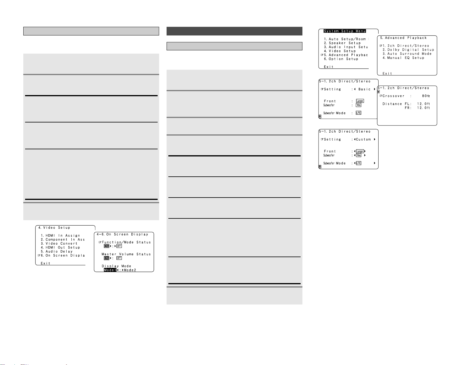
52
Advanced Setup – Part 1 Advanced Setup – Part 1
Setting the On Screen Display (OSD)
Set whether or not to display the on screen display for indications
other than the menu screens.
Press
DD HH
to select “On Screen Display”, then
press ENTER.
Press
DD HH
to select the item, then press
FF GG
to
set.
Function/Mode Status:
• ON, OFF:
Select “ON” to display the on screen display when the input
source is selected, “OFF” if you do not want to display it.
Master Volume Status:
• ON, OFF:
Select “ON” to display the on screen display when the main
volume is adjusted, “OFF” if you do not want to display it.
Display Mode:
• Mode 1:
Flickering is not prevented.
• Mode 2:
Prevents flickering of the on screen display when there is no
video signal.
Use this mode if the on screen display is not displayed in
“Mode1”.
Press ENTER.
1
2
3
1
2
Advanced Playback
Setting the 2ch Direct/Stereo
Make the 2-channel direct mode and stereo mode speaker
settings.
Press
DD HH
to select “Advanced Playback”, then
press ENTER.
Press
DD HH
to select “2ch Direct / Stereo”, then
press ENTER.
• The current settings are displayed.
1
2
3
Press
DD HH
to select the item, then press
FF GG
to
set.
Large:
Select this when using large speakers with ample low
frequency reproduction capabilities.
Small:
Select this when using small speakers without ample low
frequency reproduction capabilities.
Yes, No:
Select “Yes” when a subwoofer is connected, “No” when no
subwoofer is connected.
4
LFE:
For any channel(s) that are set to “Large”, low frequencies in
that channel’s corresponding source are directed to that
loudspeaker only. The low frequencies played from the
subwoofer are only the LFE signals and the low frequencies
of channels set to “Small”.
LFE+Main:
Low frequencies from speaker channels that have been set to
“Large” are reproduced from those speakers as well as from
the subwoofer(s).
Press ENTER.
5
Press
FF GG
to select “Custom”.
1
2
3
4
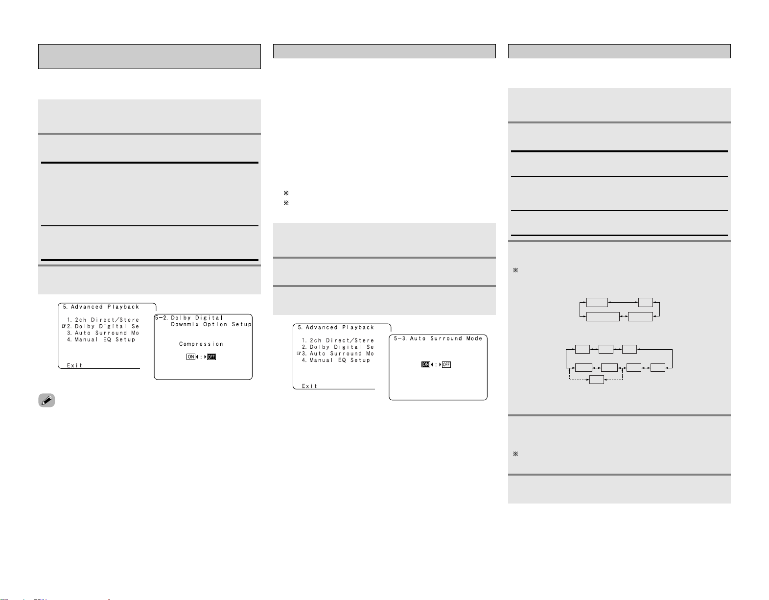
53
Advanced Setup – Part 1 Advanced Setup – Part 1
Setting the Auto Surround Mode
Set whether or not to store the surround mode last played for the
input signal.
The surround mode used at last for the 4 types of input signals
shown below is stored in the memory, and the signal is
automatically played with that surround mode the next time it is
input.
q Analog and PCM 2-channel signals (STEREO)
w 2-channel signals of Dolby Digital, DTS or other multi-
channel format (DOLBY PLII x Cinema)
e Multi-channel signals of Dolby Digital, DTS or other multi-
channel format (DOLBY/DTS SURROUND)
r PCM multi-channel signals other than Dolby Digital and
DTS (MULTI CH IN)
Default settings are indicated in ( ).
During playback in the PURE DIRECT mode, the surround
mode does not change even if the input signal is changed.
Press
DD HH
to select “Auto Surround Mode”, then
press ENTER.
Press
FF GG
to set.
Press ENTER.
1
2
3
1
2
Setting the Manual Equalizer Setup
Adjust the tone of the various speakers while listening to the
playback signals.
Press
DD HH
to select “Manual EQ Setup”, then
press ENTER.
Press
FF GG
to set, then press ENTER.
All CH:
All channels can be adjusted simultaneously.
L/R CH:
The left and right channels of the pair of speakers can be
adjusted simultaneously.
Each CH:
The channels can be adjusted separately.
Press
FF GG
to select the speaker.
The display changes as follows.
e Select “All CH”
In this case, speaker selection is not performed.
q Select “L/R CH”
w Select “Each CH”
FL/FR
SBL/SBR
C
SL/SR
FL
SBR
FR
C
SBL SR SL
SB
Press
DD HH
to select the frequency, then press
FF GG
to adjust.
The level of the various frequencies can be adjusted
between –20 dB and +6 dB.
1
2
3
4
Press ENTER.
5
(2 speakers)
(1 speaker)
Setting the Dolby Digital Downmix Option
Setup
Turn the audio compression on or off when down-mixing Dolby
Digital signals.
Press
DD HH
to select “Dolby Digital Setup”, then
press ENTER.
Press
FF GG
to set.
ON:
The dynamic range is compressed automatically according to
the combination of speakers being used.
Set “Compression” to “ON” if it seems that sound is
distorted because the input level exceeds the allowable input
for the front speakers.
OFF:
The dynamic range is not compressed.
Normally using in this mode.
Press ENTER.
1
2
3
• When a center speaker or surround speakers are not
connected, the sounds in those channels are directed to the
front speakers.
1
2
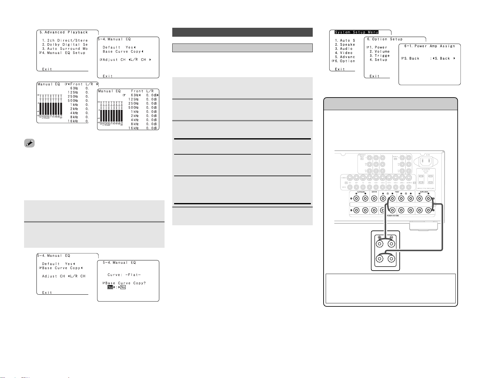
54
Advanced Setup – Part 1 Advanced Setup – Part 1
• “Base Curve Copy” is displayed after performing the Auto
Setup.
1
2
3
4
Press
DD HH
to select “Base Curve Copy”, then
press
FF
.
Press
FF
to select “Yes”, then press ENTER.
• The type of the copied correction curve is displayed in the
upper right of this screen.
2 Manually adjusting the room equalizer’s
“Flat” correction curve set with the auto
setup procedure
1
2
1
2
Setting the Power Amplifier Assignment
To suit your preference, a surround back channel’s power
amplifier can be assigned to the front channel (“Front A” or
“Front B”) for bi-amp playback, ZONE2.
Press
DD HH
to select “Option Setup”, then press
ENTER.
Option Setup
Press
DD HH
to select “Power Amp Assign”, then
press ENTER.
Press
FF GG
to set.
S. Back:
The surround back speakers are used in MAIN ZONE.
Front A, Front B:
This provides a bi-amp mode for the 2 main front speakers,
replicating the front A or front B amplifier channel’s outputs.
ZONE2:
This mode assigns the surround back amplifier channels to
provide ZONE2 speaker-level outputs from the surround back
speaker terminals.
Press ENTER.
Front Bi-Amp connections
Dynamic sound with a range wider than that of full range
systems can be played by connecting bi-amp compatible
speakers to the AVR-2807. Be sure to consult the owner’s
manual of your bi-amp-capable speakers for further
information before proceeding.
NOTE:
• When making bi-amp connections, be sure to remove
the short-circuiting bar included with the speaker.
1
2
3
4
1
2
3
SPEAKER
[L]
AVR-2807
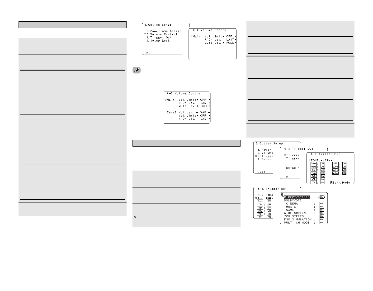
55
Advanced Setup – Part 1 Advanced Setup – Part 1
Setting the Volume Control
This sets the volume level of output.
Press
DD HH
to select “Volume Control”, then press
ENTER.
Press
DD HH
to select the item, then press
FF GG
to
set.
Vol. Limit:
Set the volume’s upper limit.
• OFF:
If you do not want to set a volume limit, select “OFF”.
In this case, the volume can be set to the AVR-2807’s
maximum volume (output) level of +18 dB, which is
extremely loud.
• –20 dB, –10 dB, 0 dB:
The volume cannot be increased above the selected levels.
1
2
Mute Lev.:
Set the level of volume attenuation in the mute mode.
• FULL
The volume is fully muted.
• –20 dB, –40 dB
The volume is lowered 20 dB (or 40 dB) from the current level.
P. On Lev.:
Set the volume level when the power is turned on.
You can adjust the MAIN ZONE volume level within the range
of –80 to +18 dB (and ZONE2 volume level within the range
of –70 to +18 dB).
• LAST
The volume set when the AVR-2807 was last used is stored
in the memory and set when the power is turned on.
• – – – (Mute)
The volume is always muted when the power is turned on.
• When the power amplifier is assigned to either of the ZONE2
channels at “Power Amp Assign”, “–VAR–” (only variable) is
displayed and the fixed level cannot be set.
Press ENTER.
3
1
2
Setting the Trigger Out
Press
DD HH
to select “Trigger Out”, then press
ENTER.
Press
FF GG
to select “MAIN” or “ZONE2”.
The power supplied from the trigger out jack turns on and off
when the power for the set zone is turned on and off.
Press
DD HH
to select the trigger out jacks, then
press ENTER.
Use the DC12V output of the AVR-2807’s 2 trigger out jacks in
association with the various input sources and surround modes.
If “ZONE = MAIN” is selected, settings can be made for the
individual surround modes.
Press
DD HH
to select the input source, then press
FF
GG
to set.
ON, OFF:
When that input source is selected, the power supplied from
the trigger out jack turns on (or off).
1
2
3
4
Press ENTER.
When “MAIN” was selected at step 3:
Press
DD HH
to select the surround mode, then
press
FF GG
to set.
ON:
If “ON” is selected when an input source set to “ON” is
selected, the power supplied from the trigger out jack turns
on.
OFF:
If “OFF” is selected when an input source set to “ON” is
selected, the power supplied from the trigger out jack turns
off.
5
6
1
2
3
4
5
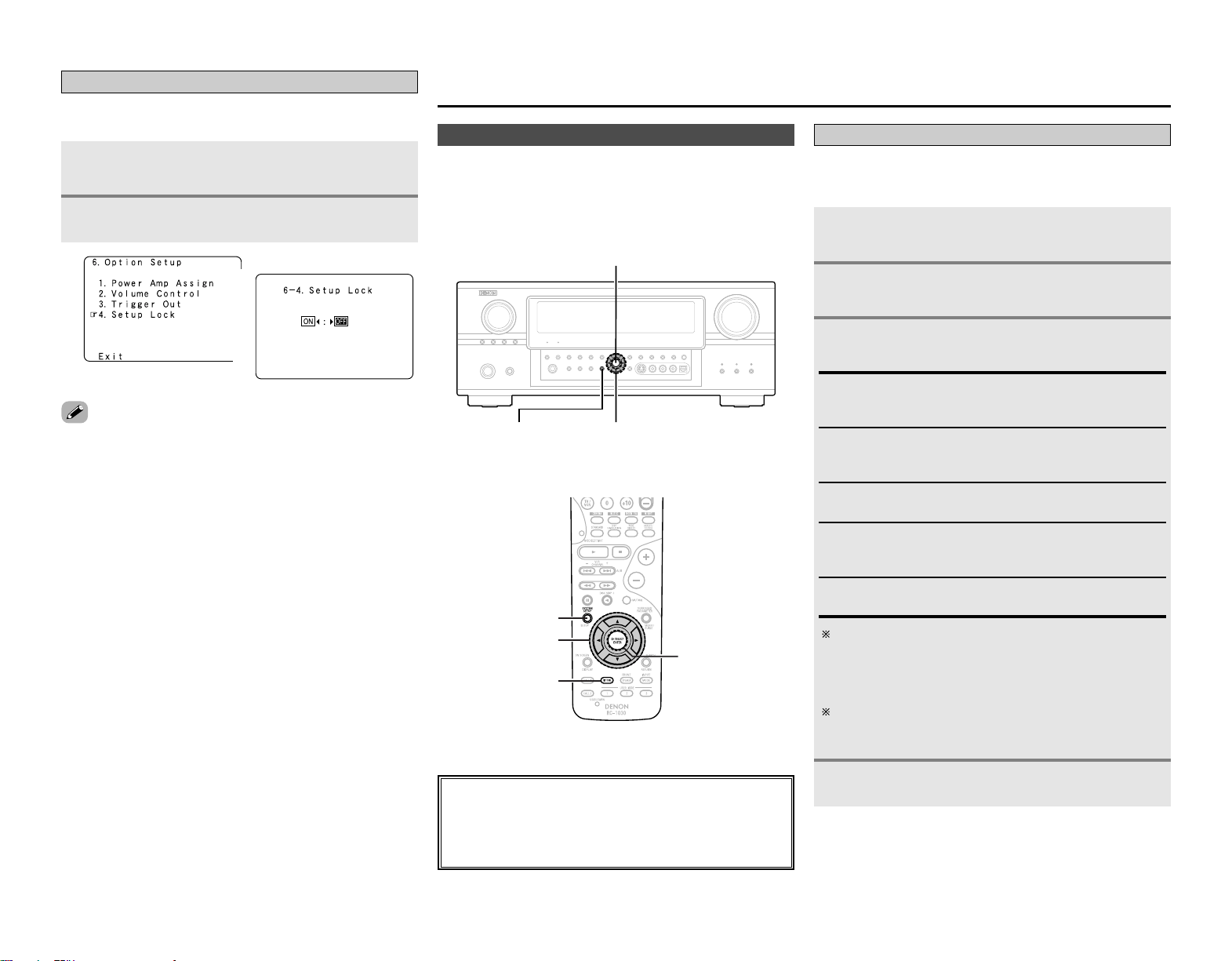
56
Advanced Setup – Part 1
Setting the Setup Lock
This sets whether or not to lock the system setup settings so
that they cannot be changed.
Press
DD HH
to select “Setup Lock”, then press
ENTER.
Press
FF
to select “ON”, then press ENTER.
• When the setup lock function is activated, the settings listed
below cannot be changed, and “SETUP LOCKED!” is displayed
when related buttons are operated.
• System setup settings
• Surround parameter settings
•Tone control settings
• Channel level settings (including test tones)
• Room EQ settings
•To unlock, press SYSTEM SETUP again and display the “Setup
Lock” screen, then select “OFF” and press ENTER.
1
2
1
2
Advanced Setup – Part 2
• If the “Auto Setup” procedure has already been performed,
there is no need to make this setting.
• Perform this setting if you wish to make the settings for your
speaker systems manually.
Speaker Setup
Press ENTER.
Setting the Speaker Configuration
Automatically set the output component and properties for the
various channels according to the combination of speakers to be
actually used for surround playback.
Press
DD HH
to select “Speaker Setup”, then press
ENTER.
Press
DD HH
to select “Speaker Config.”, then press
ENTER.
Press
DD HH
to select the speaker, then press
FF GG
to set.
Large:
Select this when using large speakers with ample low
frequency reproduction capabilities.
Small:
Select this when using small speakers without ample low
frequency reproduction capabilities.
Yes / No:
Select “Yes” when a subwoofer is connected, “No” when no
subwoofer is connected.
None:
Select this when no speaker is connected.
2spkrs / 1spkr:
Select the number of surround back speakers.
1
2
3
A subwoofer with sufficient low frequency playback
capability can better handle deep bass than most main and
surround speakers, and the system’s overall performance
will be greatly enhanced when “Small” is set for the main
(front) and surround speakers.
When “Front” is set to “Small”, “Subwoofer” is
automatically set to “Yes”, and when “Subwoofer” is set to
“No”, “Front” is automatically set to “Large”.
4
About the button names in this explanation
<>: Buttons on the main unit
[]: Buttons on the remote control unit
Button name only :
Buttons on the main unit and remote control unit
ENTER
SYSTEM SETUP
D
H
F
G
ENTER
D
H
F
G
SYSTEM SETUP
[TEST TONE]
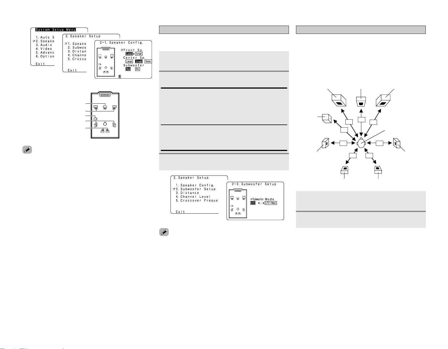
57
Advanced Setup – Part 2
• Select “Large” or “Small” not according to the actual size of
the speaker but according to the speaker’s capacity for playing
low frequency (bass sound below the frequency set for the
Crossover Frequency) signals. If you do not know, try
comparing the sound at both settings (setting the volume to a
level low enough so as not to damage the speakers) to
determine the proper setting.
1
2
3
Center Speaker
Front Speaker
Subwoofer
Surround Speaker
Surround back Speaker
hh
Setting the Subwoofer Setup
Select the method of playback of the subwoofer for playing the
low bass signals.
Press
DD HH
to select “Subwoofer Setup”, then
press ENTER.
Press
FF GG
to set.
LFE:
For any channel(s) that are set to “Large”, low frequencies in
that channel’s corresponding source are directed to that
loudspeaker only. The low frequencies played from the
subwoofer are only the LFE signals and the low frequencies
of channels set to “Small”.
LFE+Main:
Low frequencies from speaker channels that have been set to
“Large” are reproduced from those speakers as well as from
the subwoofer(s).
• The subwoofer mode setting is only valid when and “Yes” is
set for the subwoofer in the “Setting the Speaker
Configuration”.
• Select the “LFE+Main” mode if you want low frequency
signals to always be played from the subwoofer channel.
• Select the mode achieving a voluminous bass sound when
playing music or movie sources.
Press ENTER.
1
2
3
1
2
Setting the Distance
This parameter is for optimizing the timing with which the audio
signals are produced from the speakers and subwoofer
according to the listening position.
Preparations:
Measure the distances between the listening position and the
speakers (L1 to L8 on the diagram at the below).
Press
DD HH
to select “Distance”, then press
ENTER.
Press
FF GG
to select “Meters” or “Feet”.
L1
L2
L3
L4
L5
L6
L7
L8
C FRFL
SW
Listening position
SL SR
SBL SBR
1
2
Advanced Setup – Part 2
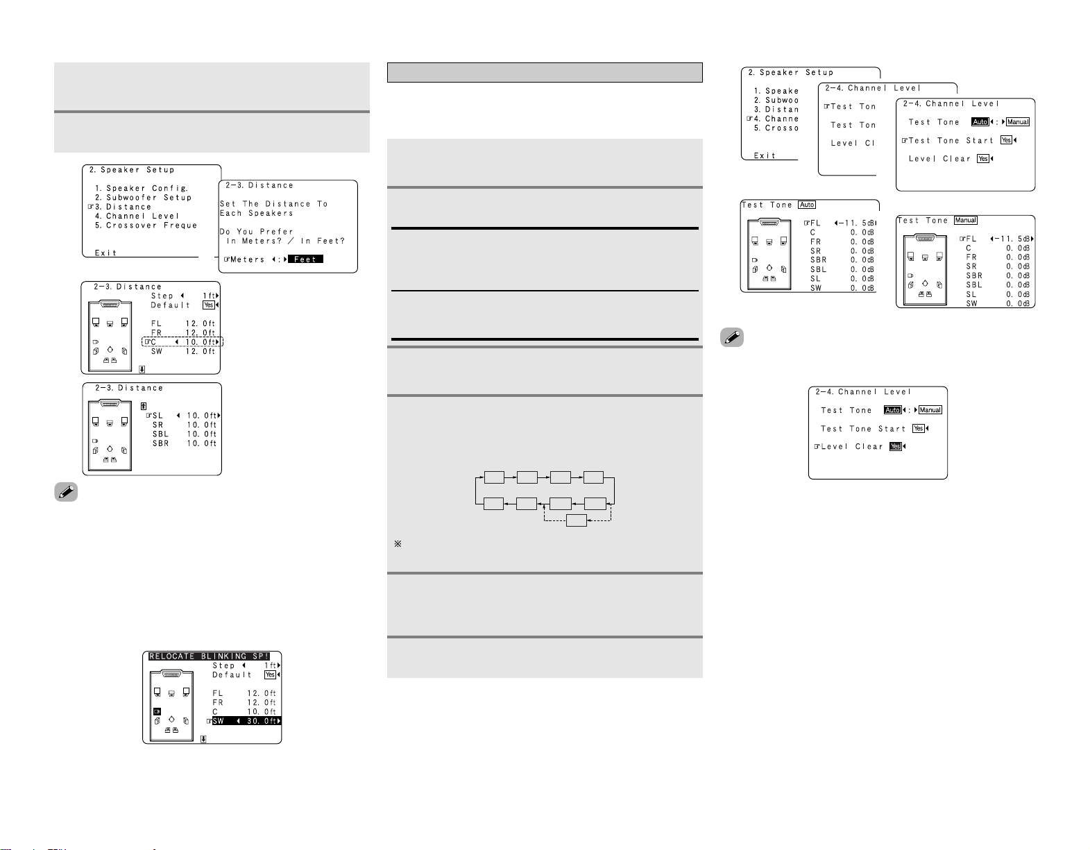
58
Advanced Setup – Part 2 Advanced Setup – Part 2
Press
DD HH
to select the speaker, then press
FF GG
to set.
3
Press ENTER.
4
1
2
3
Set the volume of the various speakers so that the sound output
from the speakers and the subwoofer seems to have the same
volume level.
Press
DD HH
to select “Channel Level”, then press
ENTER.
Press
DD HH
to select “Test Tone Start”, then press
FF
to select “Yes”.
Press
FF GG
to set.
When “Auto” mode is selected:
Press
FF GG
to adjust the volume.
•Test tones are output automatically, in the order shown
below.
Auto:
Adjust the level while listening to the test tones produced
automatically from each speaker.
Test tones are automatically emitted from each speaker.
Manual:
Adjust with the speaker from which the test tone is output
switched manually.
FL
SW
C
FR
SR
SBL
SL
SB
SBR
Setting the Channel Level
The volume can be adjusted within the range –12 dB to +12
dB.
When “Manual” mode is selected:
Press
DD HH
to select the speaker, then press
FF GG
to adjust the volume.
Press ENTER.
1
2
3
4
-1
4
-2
5
(2 speakers)
(1 speaker)
1
2
3
4
-1
4
-2
•To cancel the setting, press
HH
and select “Level Clear”, then
press
FF
and select “Yes”.
•To adjust the channel level separately for the different play
modes after setting the channel level, perform the operation on
page 34.
•Press
DD
to select “Step”, then press
FF GG
to change the
amount of variation if so desired.
• The distance changes in units of 1 foot (0.1 meters) or 0.1 foot
(0.01 meters) each time the button is pressed. Select the value
closest to the measured distance.
• Please note that the difference of distance for every
speaker should be 20 ft (6.0 m) or less. If you set an invalid
distance, a CAUTION notice, such as screen right will
appear. In such cases, move the appropriate speaker to the
position of the displayed value.
..... L1
..... L2
..... L3
..... L4
..... L5
..... L6
..... L7
..... L8
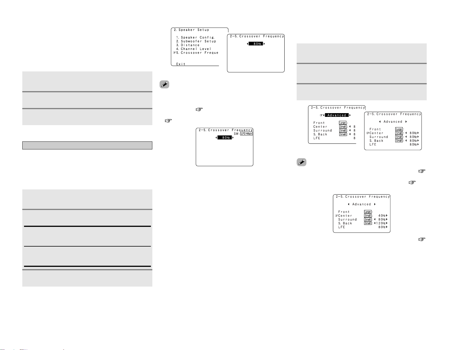
59
Advanced Setup – Part 2 Advanced Setup – Part 2
2 Adjusting the test tone using the remote
control unit
Adjustment of the test tones using the remote control unit is
only possible in the “Auto” mode and only valid in the
STANDARD (Dolby Surround and DTS Surround) mode. The
adjusted levels are automatically stored for the different
surround modes.
Press [TEST TONE].
•Test tones are output from the different speakers.
Press [TEST TONE].
Press
FF GG
to adjust the volume.
1
2
3
Setting the Crossover Frequency
Set the frequency (Hz) below which the bass sound of the
various speakers is to be output from the subwoofer.
For speakers that are set to “Small”, frequencies under the
crossover frequency are cut before the signal is output, and the
low frequency component that was cut is output from the
subwoofer or the speakers that are set to “Large”.
Press
DD HH
to select “Crossover Frequency”, then
press ENTER.
1
Press
FF GG
to set.
40, 60, 80, 90, 100, 110, 120, 150, 200, 250 Hz:
Set as desired according to your speakers’ bass playback
ability.
Advanced:
The crossover frequency can be set individually for the
different speakers.
2
Press ENTER.
3
•The crossover frequency mode is valid only when subwoofer is
set to “ON”, and when one or more speakers are set to
“Small”, as described in section “Setting the Speaker
Configuration” ( page 56, 57).
• If “LFE+Main” is set at “Subwoofer Setup”, “SW:LFE+Main”
( page 57) is displayed at the top right of the screen.
• Set to “80 Hz” when using regular speakers. When using small
speakers, we recommend setting to a higher frequency.
1
2
• If “LFE” is selected at “Setting the Subwoofer Setup” (
page 57), the frequencies can only be selected for speakers set
to “Small” at “Setting the Speaker Configuration” ( page
56, 57).
• If “LFE+Main” is set at “Setting the Subwoofer Setup” (
page 57), the frequencies can be selected regardless of the
speaker size setting.
Press
FF GG
to select “Advanced” at the
“Crossover Frequency” screen.
Press
DD HH
to select the speaker, then press
FF GG
to set.
1
2
2 Setting the crossover frequency individually
for the different channels
Press ENTER.
3
1
2
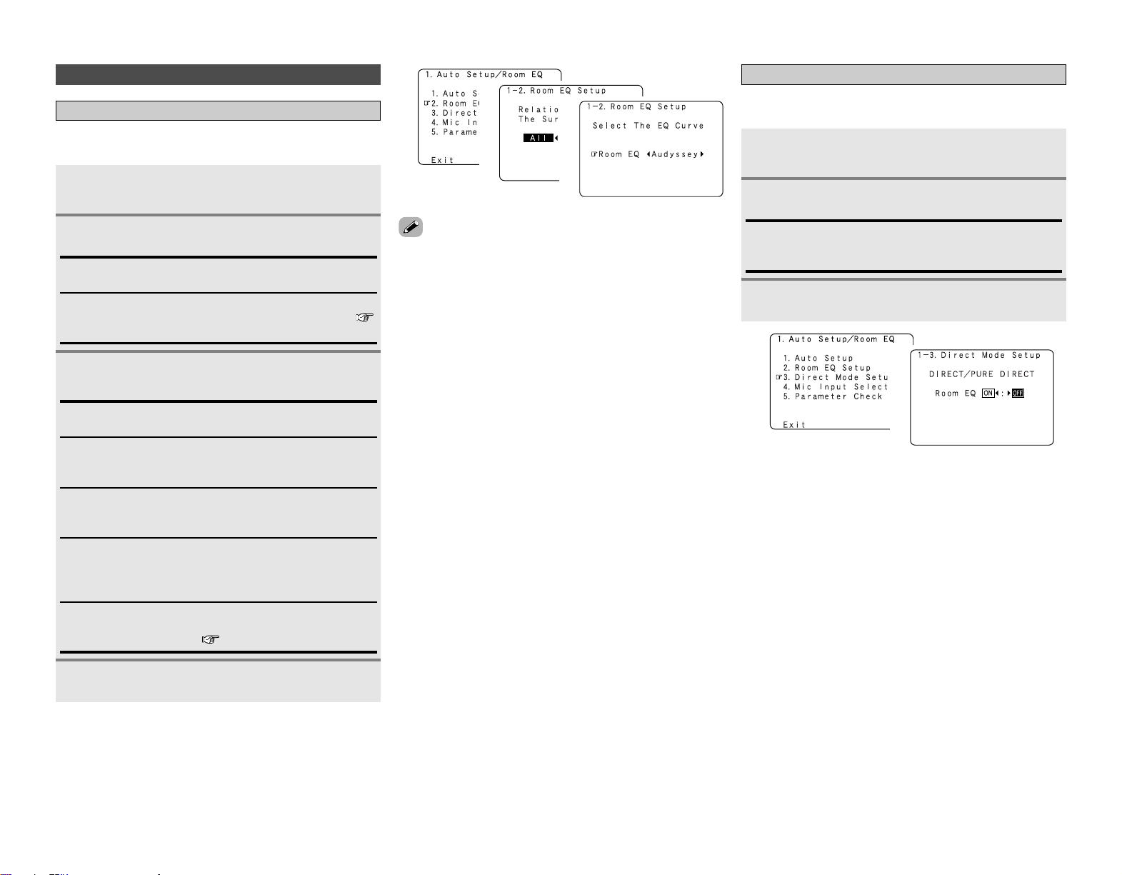
60
Advanced Setup – Part 2 Advanced Setup – Part 2
Others Setup
Setting the Room Equalizer Setup
Set the Room Equalizer setting with “All” or “Assign” for each
surround mode.
Press
FF GG
to set, then press ENTER.
All:
Sets the equalizer for all surround modes.
Assign:
Sets the equalizer individually for each surround mode (
page 24).
Setting the Direct Mode Setup
Set the ON/OFF setting of Room Equalizer, in the case of the
surround mode is in “Direct” or “Pure Direct”.
Press
DD HH
to select “Direct Mode Setup”, then
press ENTER.
Press
FF GG
to set.
When “All” is selected:
Press
FF GG
to set.
OFF:
The equalizer is not used.
Audyssey:
Adjusts the frequency response of all speakers to correct the
effects of room acoustics.
Front:
Adjusts the frequency response of the surround speakers to
match the characteristics of the front channel speakers.
Flat:
Adjusts the frequency response of all speakers to the flattest
response. This mode is suitable for multi-channel music
surround sound sources.
Manual:
Selects the setting value that was set in the “Setting the
Manual Equalizer Setup” ( page 53, 54).
• The equalizer setting of “Audyssey”, “Front” and “Flat” can be
selected after performing the Auto Setup.
• When the speaker set as “None” with the Auto Setup is
changed to on manually, the equalizer of “Audyssey”, “Front”
and “Flat” cannot be used.
• When headphones are connected, the Room Equalizer cannot
be used.
1
2
Press
DD HH
to select “Room EQ Setup”, then press
ENTER.
1
2
3
1
2
3
ON, OFF:
Select “ON” to use the room equalizer, “OFF” if you do not
want to use it.
Press ENTER.
3
1
2
Press ENTER.
4

61
Advanced Setup – Part 2 Advanced Setup – Part 2
Check the parameter
1
Press
DD HH
to select “Parameter Check”, then
press ENTER.
Press
DD HH
to select the type of equalizer, then
press ENTER.
Press
DD HH
to select the item, then press ENTER.
For instructions on checking the results of each item (
page 12).
Press
DD HH
to select “EQ Parameter Check”, then
press ENTER.
Press
FF GG
to select the speaker.
The display is only an approximate picture of the response
and that correction is happening at all frequencies.
2
3
4
5
1
•To reset:
Press
DD HH
to select “Restore” at the “Parameter Check”
screen, then press
FF
.
2
3
4
5
Setting the MIC Input Select
Sets whether the setup microphone is connected to the pin jack
(V. AUX L channel) or mini jack (SETUP MIC).
Press
DD HH
to select “Mic Input Select”, then press
ENTER.
Press
FF GG
to set.
1
2
Press ENTER.
3
1
2
Mic:
Select this to use the included microphone.
Normally set to this setting.
V.Aux L:
Select this when using a microphone other than the one
included.
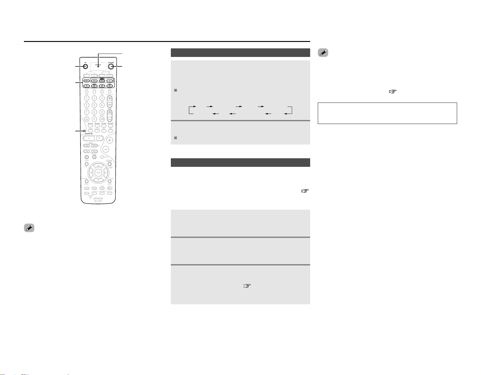
62
Operating the remote control unit
Operating the remote control unit
Operating DENON audio components
Press [MODE SELECTOR] or [MODE SELECT] for
the device to be operated.
• The button for the selected mode lights.
The mode switches as shown below each time [MODE
SELECT] is pressed:
• It may not be possible to use some of the buttons, depending
on the model and age of your equipment.
1
Setting the preset memory function
The various devices can be operated by setting the preset
memory on the included remote control unit.
For some models the remote control unit or the device may not
operate properly. In this case, use the learning function (
page 64) to store your device’s remote control signals in the
included remote control unit.
Press [MODE SELECTOR] for the device to be set
in the preset memory.
• [MODE SELECTOR] and the “LEARNED/TX” indicator blinks.
2
Input the (4-digit) number for the brand of the
device to be set in the preset memory, as shown on
the list of preset codes ( End of this manual).
• When stored correctly, [MODE SELECTOR] and the
“LEARNED/TX” indicator lights.
• There may be several preset codes for some brands. If the
remote control unit does not work properly with one code, try
inputting another code.
• Buttons that have been learned have priority over the signals
set with the preset memory function. If a learned button setting
is not needed, please erase it ( page 65).
3
Operate the component.
For details, refer to the component’s operating instructions.
2
[POWER OFF]
[MODE SELECTOR]
[MODE SELECT]
[ON/SOURCE]
[LEARNED/TX]
CD
ZONE2 TV DBS/CABLE VCR
CDR/MD TAPE DVD/VDP
Press [ON/SOURCE] and [POWER OFF] at the
same time.
• The “LEARNED/TX” indicator blinks.
1
NOTE:
•The preset memory can be set for one component only
among the following: CDR/MD, DVD/VDP and DBS/CABLE.
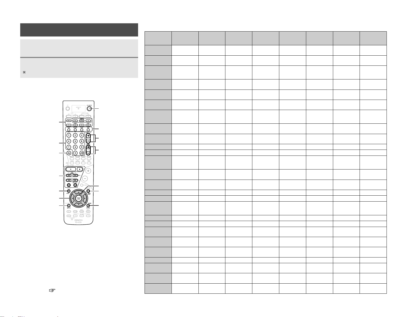
TV
/
VCR
ENTER
DD HH FF GG
RETURN /
SEARCH
DISPLAY
MENU
SETUP
DISC SKIP +
0
3
67
A / B
VCR CHANNEL
+– /
89
2
1
CHANNEL +–
TUNING /
TV VOL +–
0 ~ 9, +10
SHIFT
BAND
MEMORY
MODE
ON / SOURCE
MODE SELECTOR
Special remarks
63
TV
(Monitor)
Satellite tuner
or Cable TV
Video deck
DVD player
or
Video disc player
TunerTape deck
CD recorder
or
MD recorder
CD player
Device operated
Operating the remote control unit Operating the remote control unit
2 Functions of buttons for the different devices
[MODE SELECTOR]
SETUP
DISPLAY
TV/VCR
ON/SOURCE
MODE, MEMORY,
BAND ,SHIFT
MENU
SEARCH/RETURN
ENTER
D
H
F
G
0 ~ 9, +10
1
,
2
,
VCR CHANNEL + –,
8
9
,
A/B,
6
7
,
3
,
0
,
DISC SKIP+
TUNING/TV VOL+ –
CHANNEL+ –
Special remarks:
q It is only possible to set the preset memory for one device per mode.
When a new code is preset, the previous code is automatically
deleted.
w Note that the function names of the DVD buttons on the remote
control unit may differ for some brands. Check beforehand.
e The CD, VCR or DVD buttons can be assigned to a TV or satellite tuner
(or cable TV) ( page 65).
Operating a component stored in the preset
memory
Operate the component.
For details, refer to the component’s operating instructions.
Press [MODE SELECTOR] for the device to be
operated.
1
2
–– –
Return Return
––
––
Tuning
–
Volume control
––
CD
Play
Manual search
(forward/reverse)
Auto search (to
beginning of track)
–
–
–
–
–
q
Pause
Stop
Play
Manual search
(forward/reverse)
Auto search (to
beginning of track)
–
–
–
–
–
q
Pause
Stop
AMP (CD,
CDR/MD or TAPE)
–
–
–
–
AM/FM/XM
switching
Auto/Manual
switching
–
Preset memory
q
–
–
DVD / VDP
Play
Manual search
(forward/reverse)
Auto search (to
beginning of track)
Power on/Standby
–
–
Setup
–
q
,
w
Pause
Stop
DBS / CABLE
–
–
–
Power on/Standby
–
–
–
–
q
,
e
–
–
CDR / MD
Play
Fast forward/
Rewind
–
–
–
–
–
–
q
Pause
Stop
VCR
Play
Manual search
(forward/reverse)
Channel selection
Power on/Standby
–
–
–
–
q
Pause
Stop
–
–
–
–
–
–
–
–
–
–
–
–
–
–
Preset channel
selection
Preset station
selection (1 ~ 8),
XM channel (0 ~ 9)
–
–
–
–
–
–
Number input/
Track selection
Enter
–
Menu
Display selection
Cursor operation
–
Channels
Enter
Input mode
selection
Menu
Display selection
Cursor operation
–
–
–
–
–
–
–
–
–
–
Input mode
selection
–
–
–
TAPE
––
Preset channel
selection
–
Channel selection
–
Station selection
–– –– –
Reverse play
–
–– –– –
A/B switching
–
Disc skip (for CD
changer only)
––
Disc skip (for DVD
changer only)
–––
Return
Volume control
TV
–
–
–
Power on/Standby
–
–
–
–
q
,
e
–
–
–
Channels
Enter
Input mode
selection
Default setting
(preset code)
DENON
(0000)
DENON CDR
(0000)
–
DENON DVD
(0000)
ABC CABLE
(4007)
DENON
(0000)
HITACHI
(3010)
HITACHI
(4539)
Menu
Display selection
Cursor operation
Channel selection
–
–
–
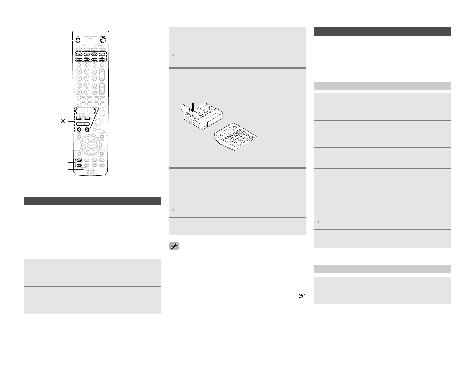
64
Operating the remote control unit Operating the remote control unit
Using the system call function
Press [SYSTEM CALL 1] for which you want to
register the operations.
• [MODE SELECTOR] and the “LEARNED/TX” indicator blinks.
Press the buttons you want to register in the
order of the operations to be performed.
Example: Press [ON].
↓↓
Press [CD] of [MODE SELECTOR].
↓↓
Press [1].
Repeat steps 3, 4 to register the desired buttons.
Registering
•A series of operations can be registered at a single button.
• This function makes it possible to for example turn the
amplifier’s power on, select the input source, turn the monitor
power’s on, turn the source device’s power on and start
playback, all by pressing a single button once.
• Up to 10 signals each can be stored at [SYSTEM CALL] (1 or 2).
• If your AV device is a brand other than DENON or if operation is
not possible using the preset memory function, the signals of a
remote control unit of that device can be stored in the AVR-
2807’s remote control unit.
• For some remote control units, it may not be possible to learn
the signals or the device may not operate properly after the
signals are learnt. In this case, use the remote control unit of
that device.
Setting the learning function
Press [USE/LEARN] with the tip of a pen etc., to
set the learn mode.
• [MODE SELECTOR] and the “LEARNED/TX” indicator blinks.
Press [MODE SELECTOR] for the device to be
operated.
• [MODE SELECTOR] and the “LEARNED/TX” indicator blinks.
•To cancel the learning function mode, press [USE/LEARN].
• If the codes could not be stored, the “LEARNED/TX” indicator
start flashing rapidly. For limited number of models, codes
cannot be stored in RC-1030.
• If [MODE SELECTOR] and the “LEARNED/TX” indicator start
flashing rapidly, this means that the memory is already full, and
the code you have just attempted to store was not stored.
To “learn” that code, first perform the resetting operation (
page 65).
Press the button to be set.
• The “LEARNED/TX” indicator stops blinking and [MODE
SELECTOR] lights.
If a button that cannot be learnt is pressed, [MODE SELECTOR]
and the “LEARNED/TX” indicator blinks.
Point the remote control units straight at each
other and press and hold in the button on the
other remote control unit to be learnt on the
AVR-2807’s remote control unit.
Other remote control unit
1
2
3
4
The AVR-2807’s remote control unit
(RC-1030)
Press [USE/LEARN].
6
2
4
Press [SYSTEM CALL] (1 or 2).
5
Operating
Press [SYSTEM CALL] (1 or 2) at which the operation
are registered.
• The stored signals are transmitted successively.
[MODE SELECTOR] and the “LEARNED/TX”
indicator lights, release the button on the other
remote control unit.
• [MODE SELECTOR] and the “LEARNED/TX” indicator blinks
again.
Other buttons can be learnt by repeating steps 2 ~ 5.
5
Press [ON/SOURCE] and [POWER OFF] at the
same time.
• The “LEARNED/TX” indicator blinks.
1
Press [MODE SELECTOR] for the device to be
operated.
3
[POWER OFF]
1
[SYSTEM CALL]
[ ]
[USE/LEARN]
[ON/SOURCE]

65
Setting the punch through function
CD, CDR/MD, TAPE, DVD/VDP or VCR mode buttons can be
assigned to unused TV and DBS/CABLE mode buttons.
For example, when CD mode operations are assigned to TV
mode buttons, the CD mode can be operated while in the TV
mode ( []).
Press [ON/SOURCE] and [POWER OFF] at the
same time.
• The “LEARNED/TX” indicator blinks.
Press [1].
• [MODE SELECTOR] (TV and DBS/CABLE) and the
“LEARNED/ TX” indicator blinks.
Press [MODE SELECTOR] for which punch
through is to be set (TV or DBS/CABLE).
• [MODE SELECTOR] (CD, CDR/MD, TAPE, DVD/VDP or VCR)
and the “LEARNED/TX” indicator blinks.
Press [MODE SELECTOR] for the device to be
punched through (CD, CDR/MD, TAPE, DVD/
VDP or VCR).
• [MODE SELECTOR] that was set will lights.
1
2
3
4
Resetting the remote control unit
Resetting the learning function
Press [USE/LEARN] with the tip of a pen etc., to
set the learn mode.
• [MODE SELECTOR] and the “LEARNED/TX” indicator blinks.
1
Press [MODE SELECTOR] for the device to be
reset.
• [MODE SELECTOR] and the “LEARNED/TX” indicator blinks.
2
Hold for 4 seconds or longer [MODE SELECTOR]
of the equipment that is to be reset and
[ON/SOURCE].
• [MODE SELECTOR] and the“LEARNED/TX” indicator blinks
again.
3
Press [USE/LEARN].
4
Resetting the punch through setting
Press [ON/SOURCE] and [POWER OFF] at the
same time.
• The “LEARNED/TX” indicator blinks.
1
Press [1].
• [MODE SELECTOR] (TV or DBS/CABLE) and the “LEARNED/
TX” indicator blinks.
2
Press [MODE SELECTOR] (TV or DBS/CABLE)
that is to be reset.
• [MODE SELECTOR] (CD, CDR/MD, TAPE, DVD/VDP or VCR)
and the “LEARNED/TX” indicator blinks.
3
Press [MODE SELECTOR] of the equipment that is
to be reset again.
4
Operating the remote control unit Operating the remote control unit
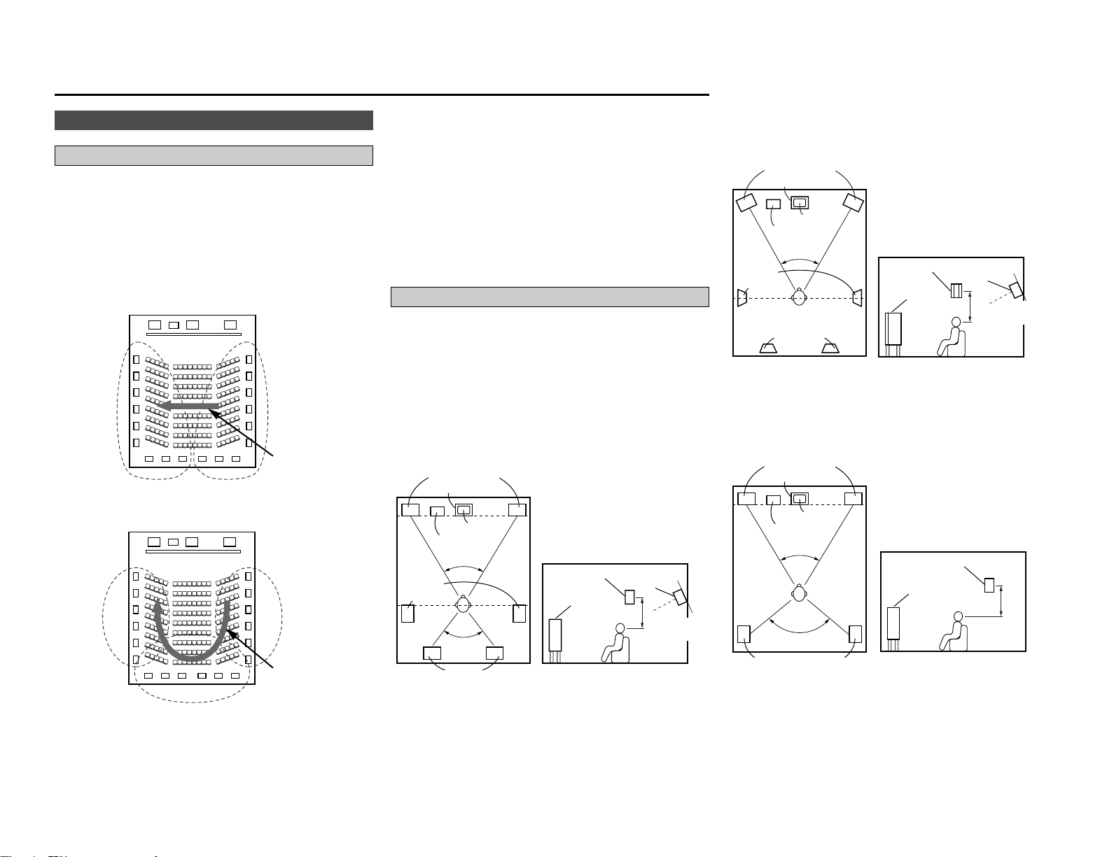
66
Additional Information
Examples of speaker layouts
Below we introduce examples of speaker layouts. Refer to these
to arrange your speakers according to their type and how you
want to use them.
[1] Using surround back speaker(s)
q When mainly playing movies
Recommended when your surround speakers are single or 2-way
speakers.
Subwoofer
Surround back speakers
Front speakers
60°
60°
Monitor
Center speaker
[As seen from above]
Surround
speakers
Surround speaker
Front speaker
2 to 3 feet
[As seen from the side]
Surround back
speaker
Point slightly
downwards
Additional Information
About the speakers
Surround back speakers
Sound position directly to the rear can be achieved easily by
adding a surround back speaker to a 5.1-channel system.
In addition, the acoustic image extending between the sides and
the rear is narrowed, thus greatly improving the expression of the
surround signals for sounds moving from the sides to the back
and from the front to the point directly behind the listening
position.
FL C
SW
FR
SR chSL ch
Change of positioning and acoustic image
with 5.1-channel systems
Movement of acoustic
image from SR to SL
FL C
SW
FR
SL ch SR ch
SB ch
Change of positioning and acoustic image
with 6.1-channel systems
Movement of
acoustic image from
SR to SB to SL
In addition to sources recorded in 6.1-channels, the surround
effect of conventional 2- to 5.1-channel sources can also be
enhanced.
2 Number of surround back speakers
We recommend using 2 speakers.
When using dipolar speakers in particular, be sure to use 2
speakers.
2 Placement of the surround left and right
channels when using surround back speakers
We recommend installing the speakers for the surround “L” and
“R” channels a bit forward.
w When playing movies and musics
Surround back
[As seen from above]
Surround
speaker
Front speaker
2 to 3 feet
[ As seen from the side ]
Surround back
speaker
Point slightly
downwards
45° ~ 60°
Surround
speakers
Subwoofer
Front speakers
Monitor
Center speaker
Surround speakers
[ As seen from above ]
[ As seen from the side ]
Front speaker
2 to 3 feet
Surround speaker
60°
[2]
When not using surround back speakers
Subwoofer
Monitor
Front speakers
Center speaker
speakers
120°
67
Additional Information Additional Information
2 Sources recorded in Dolby Surround
Sources recorded in Dolby Surround are indicated with the
following logo marks.
Dolby Surround support mark:
Manufactured under license from Dolby Laboratories.
“Dolby”, “Pro Logic” and the double-D symbol are
trademarks of Dolby Laboratories.
The AVR-2807 is equipped with a digital signal processing circuit
that lets you play program sources in the surround mode to
achieve the same sense of presence as in a movie theater.
Surround
Dolby Surround
[1] Dolby Digital
Dolby Digital is the multi-channel digital signal format developed
by Dolby Laboratories.
A total of 5.1-channels are played: 3 front channels (“FL”, “FR”
and “C”), 2 surround channels (“SL” and “SR”) and the “LFE”
channel for low frequencies.
Because of this, there is no crosstalk between channels and a
realistic sound field with a “three-dimensional” feeling (sense of
distance, movement and positioning) is achieved.
A real, overpowering sense of presence is achieved when
playing movie sources in AV rooms as well.
[2] Dolby Pro Logic II
Dolby Pro Logic II is a matrix decoding technology developed by
Dolby Laboratories. Regular music such as that on CDs is
encoded into 5 channels to achieve an excellent surround effect.
The surround channel signals are converted into stereo and full
band signals (with a frequency response of 20 Hz to 20 kHz or
greater) to create a “three-dimensional” sound image offering a
rich sense of presence for all stereo sources.
[3] Dolby Pro Logic II x
Dolby Pro Logic II x is a further improved version of the Dolby Pro
Logic II matrix decoding technology.
Audio signals recorded in 2 channels are decoded to achieve a
natural sound with up to 7.1-channels.
There are 3 modes: “Music” suited for playing music, “Cinema”
suited for playing movies, and “Game” which is optimum for
playing games.
MANUFACTURED UNDER LICENSE FROM DIGITAL
THEATER SYSTEMS, INC.
U.S. PAT. NO’S. 5,451,942; 5,956,674; 5,974,380; 5,978,762;
6,226,616; 6,487,535 AND OTHER U.S. AND WORLD–WIDE
PATENTS ISSUED AND PENDING.
“DTS”, “DTS–ES”, “Neo:6”, AND “DTS 96/24” ARE
TRADEMARKS OF DIGITAL THEATER SYSTEMS, INC. ©
1996, 2003 DIGITAL THEATER SYSTEMS, INC. ALL RIGHTS
RESERVED.
DTS Digital Surround
DTS Digital Surround is a digital surround format developed by
Digital Theater Systems of the United States.
The number of playback channels and the playing band is the
same as for Dolby Digital (5.1-channels).
The compression rate of the audio data when it was recorded on
the medium is lower than for Dolby Digital, so there is more
information when the data is decoded, resulting in richer, clearer
sound quality.
DTS-ES™
DTS-ES is a new surround format developed by Digital Theater
Systems.
A sound image and sense of positioning can be achieved by
adding a surround back (“SB”) channel to the conventional 5.1-
channels.
DTS-ES™ Discrete 6.1:
This is the latest format, in which all 6.1-channels, including the
“SB” channel, are recorded independently. Since the different
channels are independent, the sound can be designed with
total freedom.
DTS-ES™ Matrix 6.1:
With this format, the “SB” channel is matrix-encoded and
inserted into the “SL” and “SR” channels, then decoded for
the “SL”, “SR” and “SB” channels upon playback. This
achieves a surround sound more faithful to the artist’s sound
design intentions than with conventional 5.1- or 6.1-channel
systems.
DTS NEO:6 surround
This is a matrix decoding technology for 6.1-channel surround
playback of 2-channel sources.
The optimum decoding for the type of signal source to be played
can be selected. There are 2 modes.
DTS NEO:6 CINEMA:
This mode is suited for playing movies. It achieves the same
type of sound as in a movie theater, even with 2 channels.
DTS NEO:6 MUSIC:
This mode is suited for playing music. A natural sense of
expansion is added to the sound field.
DTS 96/24
DTS 96/24 is a multi-channel digital signal format developed by
Digital Theater Systems.
The sampling frequency is raised to achieve 5.1-channel playback
with high quality sound (sampling frequency: 96 kHz,
quantization: 24 bits).

68
Additional Information Additional Information
HDMI (High Definition Multimedia Interface)
HDMI is a digital interface standard for next generation TVs
based on DVI (Digital Visual Interface) standards and optimized
for use in consumer equipment.
Non-compressed digital video and multi-channel audio signals are
transmitted with a single connection.
HDMI is also compatible with HDCP (High-bandwidth Digital
Contents Protection), a technology for protecting copyrights that
encrypts digital video signals in the same was as with DVI.
•“HDMI”, “ ” and “High-Definition Multimedia
Interface” are trademarks or registered trademarks of HDMI
Licensing LLC.
AL24 Processing Plus
AL24 Processing Plus is an analog waveform reproduction
technology compatible with sampling frequencies of 192 kHz.
This brings the sound closer to that of analog waveforms and
improves the ability to play sound at low volumes with
reverberations that are normally absorbed by the hall.
Audyssey MultEQ XT
Audyssey MultEQ XT is a technology designed to provide the
optimum listening environment for multiple listeners within the
listening area. Test data collected from multiple listening points is
analyzed comprehensively and equalization that improves the
sound quality for the entire listening area is performed.
Audyssey MultEQ XT not only corrects frequency response
problems in large listening areas, it also fully automates the
surround system setup.
For a detailed description, see page 9.
• Audyssey MultEQ XT is a trademark of Audyssey Laboratories.
It is licensed under US and National Patent Applications
20030235318 and 10/700,220. Additional U.S. and Foreign
Patents pending. MultEQ and the Audyssey MultEQ logo are
trademarks of Audyssey Laboratories, Inc.. All rights reserved.
PageMeasuresCauseSymptom
PageMeasuresCauseSymptom
Troubleshooting
69
Troubleshooting
If a problem should arise, first check the following.
1. Are the connections correct?
2. Have you operated the receiver according to the Operating Instructions?
3. Are the speakers and other components operating properly?
If this unit is not operating properly, check the items listed in the table below. Should the problem
persist, there may be a malfunction. Disconnect the power immediately and contact your store of
purchase.
Display not lit and
sound not produced
when POWER switch
set to on.
• Power supply cord not plugged in
securely.
• Check the insertion of the power
supply cord plug.
22
Display lit but sound
not produced.
• Speaker cables not securely
connected.
• FUNCTION knob position is not
appropriate.
•Volume control set to minimum.
• MUTING is on.
• No digital signal is being input.
• Connect securely.
•Switch to the proper position.
•Turn volume up to suitable level.
• Switch off MUTING.
•Properly select a digital signal
input source.
7
23
23
24
47
Nothing is displayed on
monitor.
•AVR-2807’s video output terminals
and monitor’s input terminals are
not properly connected.
• Monitor’s input setting is wrong.
• The PURE DIRECT mode is set.
• Player connected with component
terminal, TV connected with video
terminal (yellow) or S-Video
terminal.
• Check that the connections are
correct.
• Set the monitor’s input selector to
the terminals to which video
signals are connected.
• Set a surround mode other than
the PURE DIRECT mode.
• Down-conversion is not possible
for progressive video signals.
Make the interlace settings on the
player.
8,
13 ~ 22
—
25
—
No DTS sound is
produced.
• DVD player’s audio output setting
is not set to bit stream.
• DVD player is not DTS-compatible.
•AVR-2807’s input setting is set to
analog
• Make the DVD player’s default
settings.
• Use a DTS-compatible player.
• Set to “AUTO” or “DTS”.
—
—
23
Copying from DVD to
VCR is not possible.
• Copying between a source such as
DVD and a VCR is not usually
possible, as DVDs are often
encoded with copy-protection
signals that prevent VCR recording.
• Copying is not possible. —
No sound is produced
from subwoofer.
• Subwoofer’s power is not on.
• Subwoofer’s initial setting is set to
“NO”.
• Subwoofer’s output is not
connected.
• The subwoofer’s channel volume
level is set to “OFF”.
•Turn on the power.
• Set the setting to “YES”.
• Connect properly.
•Turn the subwoofer’s channel
volume level up.
—
57
7, 22
34
This unit does not
operate properly when
remote control unit is
used.
• Batteries dead.
• Remote control unit too far from
this unit.
• Obstacle between this unit and
remote control unit.
• Different button is being pressed.
•
< and > ends of batteries inserted
in reverse.
• Replace with new batteries.
• Move closer.
• Remove obstacle.
•Press the proper button.
• Insert batteries properly.
3
3
3
—
3
Power has turned off
and the power
indicator is blinking red.
• The set’s internal temperature has
risen and the protection circuit has
been activated.
• The core wires of the speaker
cables are touching each other or
the AVR-2807’s rear panel,
activating the protection circuit.
•AVR-2807 is malfunctioning.
• Put the AVR-2807 in a well-
ventilated place.
•Turn off the power, then wait for
the set to fully cool off before
turning the power back on.
• Check the connections of all the
speaker cables.
•Turn off the power and contact a
DENON customer service center.
7
7
7
7
An image is not
projected with an
HDMI connection.
•AVR-2807’s HDMI output
terminals and monitor’s input
terminals are not properly
connected.
• No HDMI signal is being input.
• The connected monitor equipment
or other equipments do not
support HDCP.
• The output format of the
connected player (HDMI FORMAT)
does not match the supported
input format of connected monitor
equipments.
• Check the HDMI connection.
•Properly select HDMI signal input
source.
• The AVR-2807 will not output
video signal unless the other
equipment supports HDCP.
•Check whether the output format
of the connected player (HDMI
FORMAT) matches the supported
input format of connected monitor
equipments.
19
49, 50
19
19
The HDMI audio is not
output.
• The AVR-2807 does not play HDMI
audio signals.
• The HDMI audio signals are not
output from the connected
monitor device.
•Set the HDMI audio playback
setting at the “HDMI In Assign”
settings to “AMP”.
•Set the HDMI audio playback
setting at the “HDMI In Assign”
settings to “TV”.
49
49
No test tones are
produced.
• Surround mode is set to a mode
other than Dolby/DTS Surround.
• Set to Dolby/DTS Surround. —
No sound is produced
from surround
speakers.
• Surround mode is set to
“STEREO”.
• Set to a mode other than
“STEREO”.
—
Sound is only produced
from the center
speaker.
•You are playing a monaural source
(TV, AM radio broadcast, etc.) in
the DOLBY/DTS SURROUND
mode.
• When playing monaural sources,
select a surround mode other than
DOLBY/DTS SURROUND mode.
32, 33
“DOLBY DIGITAL” is
not displayed.
• DVD player’s digital audio output
setting is not proper.
• Check the DVD player’s audio
output setting.
For details, see the DVD player’s
operating instructions.
—
20“CHECK ANTENNA” is
displayed in the XM
mode.
•AVR-2807’s XM connectors and
the XM Connect-and-Play antenna
is not properly connected.
• Check that the connection are
correct.

Symptom Cause Measures Page
70
Troubleshooting Specifications
Specifications
2 Audio section
• Power amplifier
Rated output: Front (A, B):
110 W + 110 W (8 Ω/ohms, 20 Hz ~ 20 kHz with 0.05 % T.H.D.)
140 W + 140 W (6 Ω/ohms, 1 kHz with 0.7 % T.H.D.)
Center:
110 W (8 Ω/ohms, 20 Hz ~ 20 kHz with 0.05 % T.H.D.)
140 W (6 Ω/ohms, 1 kHz with 0.7 % T.H.D.)
Surround:
110 W + 110 W (8 Ω/ohms, 20 Hz ~ 20 kHz with 0.05 % T.H.D.)
140 W + 140 W (6 Ω/ohms, 1 kHz with 0.7 % T.H.D.)
Surround Back:
110 W + 110 W (8 Ω/ohms, 20 Hz ~ 20 kHz with 0.05 % T.H.D.)
140 W + 140 W (6 Ω/ohms, 1 kHz with 0.7 % T.H.D.)
Dynamic power: 120 W x 2 ch (8 Ω/ohms)
170 W x 2 ch (4 Ω/ohms)
Output terminals: Front: A or B 6 ~ 16 Ω/ohms
A + B 8 ~ 16 Ω/ohms
Center, Surround, Surr. Back 6 ~ 16 Ω/ohms
• Analog
Input sensitivity / input impedance: 200 mV / 47 kΩ/kohms
Frequency response: 10 Hz ~ 100 kHz: +0, –3 dB (DIRECT mode)
S/N: 102 dB (DIRECT mode)
Distortion: 0.005% (20 Hz ~ 20 kHz) (DIRECT mode)
Rated output: 1.2 V
• Digital
D/A output: Rated output — 2 V (at 0 dB playback)
Total harmonic distortion — 0.008 % (1 kHz, at 0 dB)
S/N ratio — 102 dB
Dynamic range — 96 dB
Digital input: Format — Digital audio interface
• Phono equalizer (PHONO input — REC OUT)
Input sensitivity: 2.5 mV
RIAA deviation: ±1 dB (20 Hz to 20 kHz)
S/N: 74 dB (A weighting, with 5 mV input)
Rated output / Maximum output: 150 mV / 8 V
Distortion factor: 0.03% (1 kHz, 3 V)
2 Video section
• Standard video terminals
Input / output level and impedance: 1 Vp-p, 75 Ω/ohms
Frequency response: 5 Hz ~ 10 MHz — +0, –3 dB
• S-Video terminals
Input / output level and impedance: Y (brightness) signal — 1 Vp-p, 75 Ω/ohms
C (color) signal — 0.286 Vp-p, 75 Ω/ohms
Frequency response: 5 Hz ~ 10 MHz — +0, –3 dB
• Color component video terminal
Input / output level and impedance: Y (brightness) signal — 1 Vp-p, 75 Ω/ohms
P
B/CB signal — 0.7 Vp-p, 75 Ω/ohms
P
R/CR signal — 0.7 Vp-p, 75 Ω/ohms
Frequency response: 5 Hz ~ 100 MHz — +0, –3 dB
2 Tuner section [FM] [AM]
(note: µV at 75 Ω/ohms, 0 dBf = 1 x 10
–15
W)
Receiving Range: 87.5 MHz ~ 107.9 MHz 520 kHz ~ 1710 kHz
Usable Sensitivity: 1.0 µV (11.2 dBf) 18 µV
50 dB Quieting Sensitivity: MONO 1.6 µV (15.3 dBf)
STEREO 23 µV (38.5 dBf)
S/N (IHF-A): MONO 77 dB
STEREO 72 dB
Total Harmonic Distortion (at 1 kHz): MONO 0.15%
STEREO 0.3%
2 General
Power supply: AC 120 V, 60 Hz
Power consumption: 6.0 A
1 W Max (Standby)
Maximum external dimensions: 434 (W) x 171 (H) x 429 (D) mm (17-3/32” x 6-47/64” x 16-57/64”)
Mass: 14.0 kg (30 lbs 13.84 oz)
2 Remote control unit (RC-1030)
Batteries: R6P/AA Type (3 batteries)
External dimensions: 58 (W) x 230 (H) x 37 (D) mm (2-9/32” x 9-1/16” x 1-29/64”)
Mass: 230 g (Approx. 8.1 oz) (included batteries)
* For purposes of improvement, specifications and design are subject to change without notice.
37
37
37
“NO SIGNAL” is
displayed in the XM
mode.
• The signal cannot be received. • Reposition your XM Connect-and-
Play antenna.
“OFF AIR” is displayed
in the XM mode.
• The selected channel is not
currently broadcasting.
• Select the another channel.
Receiving only XM
channels 0 and 1.
• The XM Tuner is not activated. • Contact XM Radio.

1
PRESET CODE
Magnavox 0023, 0044
Marantz 0006, 0023, 0030
Matsui 0023
McIntosh 0042
Memorex 0021, 0024, 0028, 0030,
0044
Meridian 0023
Micromega 0023
Miro 0001
Mission 0023
Mitsubishi 0022
Myryad 0023
NAD 0001
NEC 0010, 0038
NSM 0023
Nagaoka 0004
Naim 0023
Nakamichi 0020
Nikko 0024, 0025, 0027, 0059
Onkyo 0016
Optimus 0001, 0007, 0009, 0013,
0019, 0028, 0029, 0034,
0035, 0041, 0044, 0045,
0048, 0050, 0051, 0053
PMG 0024
Panasonic 0006, 0043, 0065
Parasound 0034, 0048
Philips 0023, 0042
Pink Triangle 0059
Pioneer 0007, 0044, 0053
Polk Audio 0023
Poppy 0024
Proton 0023
QED 0023
Quad 0023
CD
ADC 0004
Acoustic Research 0048
Adcom 0021, 0038
Aiwa 0003, 0018, 0023
Akai 0022
Alba 0058
Alto 0059
Arcam 0023
Ariston 0059
Audio Alchemy 0034
Audio Pro 0051
Audio Research 0023
Audio-Technica 0025
AudioTon 0023
Audiolab 0023
Audiomeca 0023
BSR 0034, 0039
Bestar 0024
Burmester 0048
Bush 0039, 0058
CDC 0048
CEC 0027
Cairn 0023
California Audio Labs
0006, 0043
Cambridge 0059
Carrera 0034
Carver 0023, 0029, 0051
Condor 0024
Craig 0058
Crown 0017
Cyrus 0023
DAK 0039
DBX 0040
DKK 0001
DMX Electronics 0023
Denon 0000
Dual 0034, 0035
Dynamic Bass 0029
EEC 0034
Eclipse 0059
Elektra 0046, 0051
Emerson 0021, 0024, 0044, 0054
Fisher 0014, 0027, 0029, 0045
GE 0002
Garrard 0039, 0041, 0046, 0048,
0049
Gemini 0059
Genexxa 0007, 0024, 0044, 0050
GoldStar 0047
Goodmans 0039, 0041, 0044, 0058,
0059
Grundig 0023
HCM 0059
Harman/Kardon 0023, 0026, 0050
Hiro 0059
Hitachi 0007, 0021
IR 0001
Inkel 0030, 0035, 0051
JVC 0012, 0061, 0064
Kenwood 0005, 0008, 0009, 0033
Kodak 0042
Krell 0023
Kyocera 0004
LXI 0044
Linn 0023
Luxman 0015
MCS 0006, 0010
MTC 0048, 0059
2 List of preset codes / Liste de codes préréglés
Quasar 0006
RCA 0002, 0007, 0011, 0021,
0029, 0044, 0053, 0066
Radiotone 0058, 0059
Realistic 0021, 0024, 0028, 0029,
0030, 0048
Revox 0023
Roadstar 0052
Rotel 0023, 0048
Royal 0048
SAE 0023
STS 0004
Sansui 0023, 0036, 0044, 0059
Sanyo 0013, 0029, 0045
Schneider 0058
Scott 0021, 0024, 0044
Sears 0044
Sharp 0009, 0030
Sherwood 0030, 0035, 0050
Shure 0010
Sonic Frontiers 0023
Sony 0001, 0056, 0057
Soundesign 0019, 0049
SuperTech 0059
Synergy 0059
Tandy 0007
Tascam 0048
Teac 0027, 0030, 0046, 0048,
0058, 0059
Technics 0006, 0037, 0043
Thomson 0011
Thorens 0023
Universum 0011, 0023, 0051
Vector Research 0034, 0047
Victor 0012

2
PRESET CODE
Wards 0011, 0023
Watson 0058
Yamaha 0008, 0025, 0032
Yorx 0052
Zenith 0058
MD
BSR 1000
Condor 1000
Denon 1111
Denver 1003
JVC 1015
Kenwood 1004, 1005, 1012
Luxman 1009
Onkyo 1007
Optimus 1013
Orion 1011
Pioneer 1013, 1017
Schneider 1000
Sharp 1006
Sherwood 1014
Sony 1001, 1002
Technics 1016
Universum 1018
Yamaha 1008
DBS
ABsat 3549
AGS 3528, 3531
ASLF 3533
Akai 3507
Akena 3528
Alba 3516
Allsat 3507
Alltech 3533
Alpha 3528
AlphaStar 3542
Amitronica 3533
Amstrad 3550
Anglo 3533
Ankaro 3533
Armstrong 3510
Asat 3507
Astacom 3528
Astra 3510, 3521
Astro 3506
Athena 3528
Axiel 3528
BT 3528, 3531
Bestar 3510
Blaupunkt 3506
Boca 3510
British Sky Broadcasting
3550
Broco 3533
Bubu Sat 3533
Canal Digital 3551
Canal Satellite 3551
Canal+ 3551
Chaparral 3508
CityCom 3501, 3546
Colombia 3528
Columbia 3502
Columbus 3528
Condor 3521
Conrad 3501, 3521
Crown 3510
Cyrus 3507
D-box 3536
DNT 3507
Daewoo 3533
Discovery 3531, 3528
Dynasat 3529
EP Sat 3516
Echostar 3505, 3513, 3518, 3533,
3543, 3551, 3556, 3560,
3569
Einhell 3510, 3533
Elta 3507
Emme Esse 3529, 3556
Engel 3533
Eurocrypt 3516
Eurosat 3510
Eurosky 3510, 3521
Eurostar 3529, 3564, 3565
Expressvu 3543
FTE 3554
Fenner 3528
Ferguson 3532
Finlandia 3516
Finlux 3516
Foxtel 3558
Fracarro 3556
Fuba 3506
GE 3519
Galaxis 3512, 3554
Gardiner 3546
General Instrument 3555
Gold Box 3551
Gooding 3520
Goodmans 3516
Gradiente 3559
Granada 3516
Grundig 3506, 3520, 3540, 3550
HTS 3543
Helium 3521
Hirschmann 3506, 3568
Hitachi 3516, 3547
Houston 3528
Hughes Network Systems
3539, 3574, 3575
Humax 3554
Huth 3510
IR 3506, 3516
ISkyB 3559
InVideo 3556
Indovision 3559
Intertronic 3510
Intervision 3521, 3524
JOK 3531
JVC 3520, 3543
K-SAT 3533
Kathrein 3506, 3507, 3523, 3527
Kreiselmeyer 3506
La Sat 3521
Lenco 3533
Lifesat 3533
Loewe 3510
Lorenzen 3521, 3538
Magnavox 3535, 3537
Manata 3531
Manhattan 3516
Marantz 3507
Maspro 3540
Matsui 3520
Max 3521
MediaSat 3551
Mediamarkt 3510
Medion 3533
Mega 3507
Memorex 3537
Metronic 3510
Metz 3506
Micro 3533
Micro Elektronic 3533
Microtec 3533
Minerva 3520
Mitsubishi 3539
Morgan’s 3502, 3510
Multichoice 3526, 3558
Myryad 3507
Mysat 3533
Netsat 3559

3
PRESET CODE
Neuhaus 3533
Neusat 3533
Next Level 3555
Nikko 3533
Nokia 3516, 3536, 3541, 3557,
3563, 3573
Nordmende 3516
Okano 3510, 3528
Orbit 3562
Oxford 3528
Pace 3509, 3516, 3517, 3534,
3545, 3550, 3559
Palladium 3520
Panasat 3522, 3558
Panasonic 3511, 3530, 3550
Panda 3516
Patriot 3528
Philips 3503, 3507, 3516, 3520,
3531, 3535, 3537, 3539,
3540, 3551, 3567, 3574
Pioneer 3514, 3551
Prima 3545
Profile 3531
Promax 3516
Prosat 3524
Proscan 3515
Pye 3520
Quadral 3524
Quelle 3521
RCA 3504, 3515, 3519, 3552
RFT 3507
Radio Shack 3555
Radiola 3507
Roadstar 3533
Rover 3524, 3533
SEG 3538
SKR 3533
SKY 3553, 3559
SM Electronic 3533
Saba 3531
Sabre 3516
Sagem 3548, 3572
Samsung 3571
Sat Team 3533
Satec 3533
Satline 3524
Schneider 3528
Seemann 3510
Seleco 3556
Siemens 3506
Skantin 3533
Sky Television 3561
Skymaster 3524, 3533
Skymax 3507
Smart 3502
Sony 3525, 3550
Star 3559
Star Choice 3555
Strong 3502, 3558
Sumida 3510
Sunsat 3533
Sunstar 3510
Super Sat 3529
TPS 3548
Tantec 3516
Tatung 3516
Technisat 3570
Technowelt 3521
Teco 3510
Teleka 3510
Telestar 3500
Televes 3516
Televisa 3559
Thomson 3516, 3532, 3551, 3566
Thorn 3516
Tonna 3528
Toshiba 3539, 3544
Triax 3501
Uniden 3535, 3537
Unisat 3507, 3510
Universum 3506, 3520
VTech 3546
Variosat 3506
Ventana 3507
Vestel 3538
Wela 3533
Wewa 3516
Wisi 3506, 3516
World Sat 3531
XSat 3528
Xcom Multimedia 3528
Zehnder 3500, 3546
Zenith 3553
Zeta Technology 3507
Zwergnase 3510
VCR
ASA 3006, 3018
AVP 3034
Adelsound 3002
Admiral 3014, 3026
Adventura 3000
Adyson 3017
Aiko 3030
Aiwa 3000, 3006, 3033, 3034
Akai 3009, 3020, 3031
Akiba 3017
Akura 3017
Alba 3017, 3026, 3030, 3031,
3034
Allstar 3018
America Action 3030
American High 3005
Amstrad 3000, 3030
Anam 3006, 3023, 3028, 3029,
3030
Anam National 3023, 3028, 3036, 3050
Anitech 3017
Ansonic 3002
Aristona 3018
Asha 3029
Asuka 3006
Audiosonic 3030
Audiovox 3006
Baird 3000, 3009, 3019
Basic Line 3017, 3030
Beaumark 3029
Bell & Howell 3019
Bestar 3030
Blaupunkt 3023, 3025, 3028
Blue Sky 3030
Bondstec 3017
Brandt 3032
Brandt Electronic 3009
Broksonic 3001, 3021, 3024, 3026,
3033, 3037
Bush 3017, 3026, 3030, 3034
CCE 3017, 3030
CGE 3000
Calix 3006
Canon 3005
Carena 3026
Carrefour 3012
Carver 3018
Cathay 3030
Cimline 3017
Cineral 3030
Citizen 3006, 3030
Colt 3017
Combitech 3034
Condor 3030
Craig 3006, 3013, 3017, 3029

4
PRESET CODE
Crown 3017, 3030
Curtis Mathes 3005, 3009, 3015, 3023,
3044
Cybernex 3029
Cyrus 3018
Daewoo 3012, 3030, 3043
Dansai 3017
De Graaf 3010
Decca 3000, 3018
Denon 3010
Diamant 3006
Domland 3026
Dual 3009
Dumont 3000, 3018, 3019
Dynatech 3000
ESC 3029, 3030
Elbe 3007
Elcatech 3017
Electrohome 3006
Electrophonic 3006
Elin 3029
Elsay 3017
Elta 3017, 3030
Emerex 3003
Emerson 3000, 3001, 3006, 3011,
3021, 3024, 3026, 3030,
3037
Ferguson 3009, 3032
Fidelity 3000
Finlandia 3018, 3019
Finlux 3000, 3010, 3018, 3019
Firstline 3006, 3011, 3012, 3017,
3026
Fisher 3013, 3019
Flint 3026
Fuji 3004, 3005
Fujitsu 3000
Funai 3000
GE 3005, 3014, 3015, 3029,
3044
GEC 3018
Galaxis 3030
Garrard 3000
General Technic 3033
Genexxa 3019
Go Video 3035
GoldHand 3017
GoldStar 3006, 3007, 3027
Goodmans 3000, 3006, 3017, 3030
Gradiente 3000
Graetz 3009, 3019, 3029
Granada 3018, 3019
Grandin 3000, 3006, 3017
Grundig 3017, 3018, 3025, 3028
HCM 3017
HI-Q 3013
Hanimex 3034
Hanseatic 3006
Harley Davidson 3000
Harman/Kardon 3007, 3018
Harwood 3017
Hinari 3002, 3017, 3029, 3034
Hisawa 3034
Hischito 3012
Hitachi 3000, 3002, 3009, 3010,
3029
Hornyphone 3018
Hughes Network Systems
3010
Hypson 3017
IR 3002, 3009, 3010, 3012,
3013, 3017, 3018, 3019,
3020, 3026, 3028, 3029,
3033
ITT 3009, 3019, 3020, 3029
ITV 3006, 3030
Imperial 3000
Ingersol 3002
Inno Hit 3017, 3029
Interfunk 3018
Intervision 3000, 3006, 3026, 3030
Irradio 3017, 3018
JVC 3009, 3016
Jensen 3009
KEC 3006, 3030
KLH 3017
Kaisui 3017
Kendo 3020, 3026
Kenwood 3007, 3009, 3016
Kimari 3013
Kneissel 3034
Kodak 3005, 3006
Korpel 3017
Kuba Electronic 3013
Kyoto 3017
LXI 3006
Lenco 3030
Leyco 3017
Lloyd’s 3000
Loewe 3002, 3006, 3018, 3023,
3036, 3050
Logik 3002, 3017, 3029
Luxor 3011, 3014, 3019, 3020
M Electronic 3000, 3007
MEI 3005
MGA 3011, 3029
MGN Technology 3029
MTC 3000, 3029
Magnasonic 3030
Magnavox 3000, 3005, 3008, 3018,
3022, 3038
Magnin 3029
Manesth 3012, 3017
Marantz 3005, 3018
Marta 3006
Matsui 3002, 3026, 3033, 3034
Matsushita 3005, 3023, 3036
Medion 3033
Memorex 3000, 3005, 3006, 3008,
3013, 3014, 3019, 3023,
3026, 3029, 3033, 3036,
3037, 3046, 3050, 3052
Memphis 3017
Metz 3006, 3023, 3025, 3036,
3050
Minerva 3025
Minolta 3010
Mitsubishi 3011, 3014, 3016, 3018
Motorola 3005, 3014
Multitech 3000, 3017
Murphy 3000
Myryad 3018
NAD 3019
NAP 3008
NEC 3007, 3009, 3016, 3019
National 3028
Neckermann 3018
Nesco 3017
Nikkai 3017, 3030
Nikko 3006
Noblex 3029
Nokia 3009, 3019, 3020, 3029
Nordmende 3009, 3032
Oceanic 3000, 3009
Okano 3031, 3033
Olympus 3005, 3028
Optimus 3006, 3014, 3019, 3023,
3035, 3036, 3047, 3048,
3050, 3052
Orion 3001, 3002, 3021, 3024,
3026, 3033, 3034, 3037
Osaki 3000, 3006, 3017

5
PRESET CODE
Otake 3026
Otto Versand 3018
Palladium 3006, 3009, 3017
Panasonic 3005, 3023, 3027, 3028,
3036, 3040, 3048, 3050,
3052, 3053
Pathe Cinema 3002, 3011
Pathe Marconi 3009
Penney 3005, 3006, 3007, 3010,
3029
Pentax 3010
Perdio 3000
Philco 3005, 3007, 3026, 3037
Philips 3005, 3018, 3038, 3041,
3049, 3051
Phonola 3018
Pilot 3006
Pioneer 3016, 3018
Polk Audio 3018
Portland 3030
Pro Vision 3030
Profitronic 3029
Proline 3000
Proscan 3015, 3044
Prosonic 3030
Protec 3017
Pulsar 3008
Pye 3018
Quasar 3005, 3023, 3036, 3050
Quelle 3018
RCA 3005, 3010, 3014, 3015,
3020, 3022, 3029, 3044
RFT 3017
Radialva 3006, 3014
Radio Shack 3000, 3046
Radiola 3018
Radix 3006
Randex 3006
Realistic 3000, 3005, 3006, 3013,
3014, 3019
ReplayTV 3039, 3040
Rex 3009
Roadstar 3006, 3017, 3029, 3030
Runco 3008
SBR 3018
SEG 3029
SEI 3002, 3018
STS 3010
Saba 3009, 3032
Saisho 3002, 3026
Salora 3011, 3020
Samsung 3012, 3029, 3035
Sanky 3008, 3014
Sansui 3000, 3009, 3016, 3026,
3037
Sanwa 3002
Sanyo 3013, 3019, 3029
Saville 3034
Schaub Lorenz 3000, 3009, 3019
Schneider 3000, 3017, 3018
Scott 3011, 3012, 3021, 3024
Sears 3000, 3005, 3006, 3010,
3013, 3019
Seleco 3009
Semp 3012
Sentra 3017
Sharp 3014
Shintom 3017, 3019
Shivaki 3006
Shogun 3029
Shorai 3002
Siemens 3006, 3018, 3019, 3025
Siera 3018
Silva 3006
Singer 3012, 3017
Sinudyne 3002, 3018
Sonneclair 3017
Sontec 3006
Sony 3000, 3003, 3004, 3005,
3042, 3045
Soundwave 3006, 3026
Ssangyong 3017
Stern 3030
Sunkai 3033
Sunstar 3000
Suntronic 3000
Sunwood 3017
Supra 3006
Sylvania 3000, 3005, 3011, 3018
Symphonic 3000
TMK 3029
Taisho 3002, 3026
Tandberg 3030
Tandy 3000, 3019
Tashiko 3000
Tatung 3000, 3009, 3018
Teac 3000, 3009, 3030, 3043
Tec 3017, 3030
Tech Line 3017
Technics 3005, 3023, 3028
Teknika 3000, 3005, 3006
Teleavia 3009
Telefunken 3009, 3032
Teletech 3017
Tenosal 3017
Tensai 3000
Thomas 3000
Thomson 3009, 3015, 3016, 3032
Thorn 3009, 3019
Tivo 3041, 3042
Tokai 3017
Toshiba 3009, 3011, 3012, 3018
Totevision 3006, 3029
Uher 3029
Ultravox 3030
Unitech 3029
Universum 3000, 3006, 3018, 3020,
3025, 3029
Vector 3012
Vector Research 3007
Victor 3009, 3016
Video Concepts 3012
Videosonic 3029
Wards 3000, 3005, 3010, 3013,
3014, 3015, 3017, 3018,
3022, 3029, 3044
Watson 3018
White Westinghouse
3017, 3026, 3030
XR-1000 3000, 3005, 3017
Yamaha 3007
Yamishi 3017
Yokan 3017
Yoko 3029
Zenith 3000, 3004, 3008, 3026,
3037
CDR
Denon 0000, 0001
HHB 0500
Kenwood 0501
Marantz 0501
NAD 0503
Philips 0501
Pioneer 0500, 0502
RCA 0502
CABLE
ABC 4001, 4002, 4005, 4006
Alcatel 4028, 4029
Americast 4030
Bell & Howell 4005

6
PRESET CODE
Bell South 4030
Birmingham Cable Communications
4012
British Telecom 4001
Cable & Wireless 4034
Cabletime 4018, 4024
Daeryung 4002
Filmnet 4017
France Telecom 4019, 4028, 4029
Galaxi 4002
General Instrument 4020, 4025
GoldStar 4008
Hamlin 4003, 4011
Jerrold 4001, 4004, 4005, 4012,
4020, 4025
MNet 4017
Macab 4026
Memorex 4000
Motorola 4020, 4035
Mr. Zap 4036
Noos 4026
Ono 4034
PVP Stereo Visual Matrix
4001
Pace 4009, 4032, 4034
Panasonic 4000, 4007
Paragon 4000
Philips 4015, 4016
Pioneer 4008, 4023, 4027, 4037
Pulsar 4000
Quasar 4000
Regal 4011, 4014
Runco 4000
Sagem 4026
Samsung 4008
Scientific Atlanta 4002, 4006, 4013, 4021,
4027, 4037
Sony 4031
Starcom 4001
Supercable 4012
Tele+1 4017
Tocom 4004
Toshiba 4000
United Cable 4001
Videoway 4010
Visionetics 4033
Visiopass 4019
Zenith 4000, 4022, 4030
TV
A-Mark 4501
A.R. Systems 4593
AOC 4501, 4508, 4512, 4519,
4554
AWA 4502
Acura 4502
Admiral 4531, 4545, 4585
Adventura 4516
Adyson 4564
Aiko 4530
Aiwa 4612
Akai 4502, 4512, 4562, 4565,
4596
Akib 4572
Akiba 4514, 4565, 4571, 4572,
4584
Akura 4565, 4569
Alaron 4552, 4563
Alba 4502, 4513, 4514, 4565,
4579, 4607
Allorgan 4572
Allstar 4514
Ambassador 4550
America Action 4553
Amplivision 4564
Ampro 4619
Amstrad 4502, 4514, 4549, 4550,
4579, 4581
Anam 4501, 4502, 4553, 4568
Anam National 4522, 4568, 4605
Anglo 4569
Anitech 4502
Ansonic 4502, 4514, 4578
Arcam 4563, 4564
Archer 4501
Aristona 4514, 4593
Asora 4502
Asuka 4565
Atlantic 4561
AudioTon 4564, 4569
Audiosonic 4514, 4536
Audiovox 4501, 4530, 4553, 4583,
4599
Autovox 4561
BPL 4571
BSR 4572
BTC 4565
Baird 4526, 4527, 4557, 4558,
4562, 4564
Basic Line 4502, 4565
Baur 4514, 4590, 4592
Baysonic 4553
Bazin 4564
Beaumark 4551
Beko 4578, 4615
Belcor 4508
Bell & Howell 4505, 4542
Beon 4514
Best 4578
Bestar 4514, 4578, 4580
Binatone 4564
Blaupunkt 4560, 4573, 4574
Blue Sky 4565, 4607
Blue Star 4571
Boots 4564
Bradford 4553
Brandt 4536, 4575
Brinkmann 4512, 4582
Britannia 4563
Brockwood 4508
Broksonic 4501, 4567, 4585
Bush 4502, 4513, 4514, 4565,
4571, 4572, 4576, 4579,
4580, 4607
CCE 4514, 4564
CGE 4578, 4582
CS Electronics 4563
CXC 4553
Candle 4512, 4516, 4523, 4555
Canton 4565
Carad 4598
Carena 4514, 4584
Carnivale 4512
Carrefour 4513
Carver 4521, 4548
Cascade 4502
Cathay 4514
Celebrity 4500
Centurion 4514
Cimline 4502
Cineral 4530, 4583
Citizen 4512, 4515, 4516, 4523,
4524, 4530, 4555, 4570
City 4502
Clairtone 4554
Clarivox 4514
Clatronic 4578
Concerto 4523
Condor 4578
Contec 4502, 4513, 4553, 4554,
4563
Continental Edison 4536, 4588

7
PRESET CODE
Cosmel 4514
Craig 4553
Crosley 4521
Crown 4502, 4514, 4515, 4553,
4578, 4582
Curtis Mathes 4505, 4512, 4515, 4517,
4518, 4521, 4523, 4524,
4531, 4539, 4542, 4547,
4583, 4586, 4618, 4622,
4626
Cybertron 4565
DER 4557, 4558
Daewoo 4502, 4508, 4514, 4515,
4530, 4542, 4580, 4583,
4599, 4600
Dainichi 4565
Dansai 4514
Dayton 4502
Daytron 4508
De Graaf 4562
Decca 4514, 4526
Denko 4569
Denon 4539
Denver 4514
Desmet 4502, 4514
Diamant 4514
Dixi 4502, 4514
Dual 4514, 4564
Dual Tec 4564
Dumont 4506, 4508, 4525
Dwin 4617, 4620
ECE 4514
Elbe 4564
Electroband 4500, 4554
Electa 4569
Elin 4514
Elite 4565
Elta 4502
Emerson 4508, 4515, 4542, 4550,
4551, 4552, 4553, 4554,
4567, 4570, 4571, 4585,
4599, 4600
Emperor 4571
Envision 4512
Erres 4504, 4514
Etron 4502
Euromann 4514, 4569
Europa 4514
Europhon 4564
Expert 4561
Exquisit 4514
Fenner 4502, 4580
Ferguson 4514, 4527, 4536, 4557,
4558, 4575
Fidelity 4558, 4563
Filsai 4564
Finlandia 4562
Finlux 4514, 4525, 4526, 4552
Firstline 4502, 4563, 4564, 4572,
4607
Fisher 4542, 4544, 4562, 4564,
4578
Flint 4584
Forgestone 4558
Formenti 4514
Fortress 4531
Fraba 4514, 4578
Friac 4502, 4578
Frontech 4545, 4569
Fujitsu 4526, 4552, 4561, 4609
Funai 4549, 4552, 4553, 4569,
4572
Futuretech 4553
GBC 4502, 4565, 4580
GE 4510, 4511, 4517, 4518,
4522, 4531, 4538, 4551,
4571, 4583, 4618, 4622,
4626
GEC 4514, 4526, 4564
GPM 4565
Galaxi 4514
Galaxis 4514, 4578
Geloso 4502
General 4555
General Technic 4502
Genexxa 4545, 4565
Gibralter 4506, 4508, 4512
GoldStar 4508, 4512, 4514, 4515,
4523, 4536, 4551, 4564
Gooding 4588
Goodmans 4513, 4514, 4526, 4552,
4564, 4579, 4580, 4600
Gorenje 4578
Gradiente 4520, 4523, 4548
Graetz 4545
Granada 4514, 4526, 4562, 4564
vrandin 4571, 4598
Grundig 4514, 4525, 4560, 4588,
4593, 4595
Grunpy 4552, 4553
HCM 4502, 4571, 4581
Halifax 4564
Hallmark 4551
Hampton 4563, 4564
Hanimex 4572
Hanseatic 4514, 4593
Hantarex 4514
Hantor 4514
Harley Davidson 4552
Harman/Kardon 4521
Harvard 4553
Harwood 4502, 4514, 4581
Hema 4502, 4564
Hikona 4565
Hinari 4502, 4513, 4514, 4552,
4565
Hisawa 4571, 4584
Hitachi 4505, 4513, 4523, 4536,
4539, 4541, 4545, 4564,
4594
Hornyphone 4514
Huanyu 4563, 4580
Hyper 4502, 4563, 4564
Hypson 4514, 4569, 4571
ICE 4564, 4569, 4579
ICeS 4565
IR 4503, 4504, 4513, 4514,
4525, 4526, 4527, 4531,
4534, 4535, 4536, 4545,
4557, 4558, 4559, 4560,
4561, 4563, 4564, 4566,
4572, 4573, 4578, 4580,
4590, 4592, 4593
ITS 4579
ITT 4545
ITV 4514, 4569
Iberia 4514
Imperial 4578, 4582
Indiana 4514
Infinity 4521
Ingelen 4545
Ingersol 4502
Inno Hit 4526
Innova 4514
Inteq 4506
Interbuy 4514, 4569
Interfunk 4514, 4545, 4592
Internal 4514
Intervision 4514, 4564, 4569
Irradio 4565, 4579

8
PRESET CODE
Isukai 4565
JBL 4521
JCB 4500
JVC 4513, 4520, 4532, 4557,
4579, 4606
Janeil 4516
KB Aristocrat 4545
KEC 4553
KTV 4512, 4515, 4553, 4554,
4564, 4570
Kaisui 4502, 4563, 4564, 4565,
4571
Kamp 4563
Kapsch 4545, 4561
Karcher 4598
Kasui 4571
Kathrein 4593
Kawasho 4563
Kaypani 4519
Kendo 4514
Kennedy 4561
Kenwood 4508, 4512
Kingsley 4563
Kloss 4516
Kneissel 4514, 4580, 4598
Kolster 4514
Konka 4602, 4603, 4604, 4613,
4614
Korpel 4514
Kosmos 4514
Koyoda 4502
Kyoshu 4581
Kyoto 4545
LG 4523
LXI 4517, 4521, 4542, 4543,
4551, 4618
Leyco 4514, 4526, 4569, 4572
Liesenk & Tter 4514
Liesenkotter 4514, 4573
Lifetec 4514, 4565, 4580
Loewe 4592
Logik 4505
Luma 4561
Lumatron 4564
Luxman 4523
Luxor 4559
M Electronic 4502, 4514, 4536, 4545,
4564, 4580, 4587
MEI 4554
MGA 4508, 4512, 4540, 4551
MTC 4508, 4512, 4523, 4524,
4554, 4563, 4592
Magnafon 4527, 4563
Magnavox 4509, 4512, 4513, 4521,
4533, 4552, 4555, 4556,
4624
Magnum 4514
Majestic 4505
Manesth 4564, 4569
Marantz 4512, 4514, 4521, 4593
Mark 4514
Matsui 4502, 4503, 4513, 4514,
4526, 4550, 4562, 4564,
4572, 4576, 4579, 4588
Matsushita 4568, 4605
Mediator 4504, 4514
Medion 4607
Megas 4598
Megatron 4501, 4539, 4551
Memorex 4502, 4505, 4523, 4540,
4542, 4551, 4552, 4568,
4585
Metz 4577
Midland 4506, 4515, 4517, 4518,
4538, 4618
Minerva 4525, 4588
Minoka 4581
Minutz 4510
Mitsubishi 4508, 4513, 4531, 4535,
4540, 4551, 4592
Mivar 4563
Monaco 4502
Motorola 4522, 4531
Multibroadcast 4558
Multitech 4502, 4553, 4563, 4564
Murphy 4515, 4526, 4545, 4563
Myryad 4593
NAD 4543, 4547, 4551
NEC 4508, 4512, 4513, 4523,
4548, 4584, 4589
NEI 4514
NTC 4530
Nakimura 4514, 4580
Nakio 4587
National 4566
Neckermann 4514, 4590, 4593
Nesco 4552
Netsat 4514
Neufunk 4514, 4593
New Tech 4564
Nicamagic 4563
Nikkai 4514, 4526, 4563, 4565,
4569
Nikko 4512, 4530, 4551
Nobliko 4525, 4563
Nokia 4587
Nordmende 4536
Noshi 4507
Novak 4504
Novatronic 4514
Oceanic 4545
Okano 4502, 4514, 4569, 4578
Omega 4569
Onwa 4553
Optimus 4542, 4547, 4568, 4605
Optonica 4531, 4546
Orion 4514, 4550, 4552, 4567,
4572, 4576, 4585
Orline 4514, 4565
Osaki 4526, 4564, 4565, 4569,
4581
Osio 4514
Oso 4565
Osume 4526
Otto Versand 4513, 4514, 4564, 4590,
4592, 4593
Pael 4563
Palladium 4578, 4582
Panama 4564, 4569
Panasonic 4518, 4522, 4537, 4545,
4566, 4568, 4577, 4605
Panavision 4514
Pathe Cinema 4563
Pausa 4502
Penney 4501, 4507, 4508, 4510,
4511, 4512, 4515, 4517,
4518, 4523, 4524, 4538,
4543, 4551, 4618, 4626
Perdio 4514, 4545
Philco 4508, 4509, 4512, 4521,
4533, 4539, 4585
Philips 4504, 4514, 4521, 4558,
4580, 4593
Phoenix 4563
Phonola 4504, 4514
Pilot 4508, 4512, 4515
Pioneer 4536, 4545, 4547, 4608
Plantron 4502
Playsonic 4564
Portland 4508, 4515, 4530
Precision 4564
Prima 4569

9
PRESET CODE
Princeton 4616
Prinz 4559
Prism 4518
Profex 4502
Profi 4502
Profitronic 4514
Proline 4526
Proscan 4517, 4618
Prosonic 4514
Protech 4502, 4514, 4564, 4569,
4582, 4607
Proton 4501, 4519, 4551, 4586
Pulsar 4506, 4508
Pye 4504
Quasar 4518, 4522, 4546, 4568,
4605
Quelle 4503, 4514, 4525, 4573,
4574, 4590, 4592
Questa 4513
R-Line 4514
RBM 4525
RCA 4507, 4508, 4517, 4518,
4529, 4531, 4538, 4608,
4618, 4621, 4622, 4623,
4626, 4627
RFT 4526
Radialva 4514, 4565
Radio Shack 4508, 4512, 4515, 4517,
4523, 4542, 4546, 4551,
4553, 4618
Radiola 4504, 4514
Radiomarelli 4514
Radiotone 4502, 4514, 4569
Rank Arena 4513
Realistic 4508, 4512, 4515, 4523,
4542, 4546, 4551, 4553
Recor 4514
Redstar 4514
Reflex 4514
Revox 4514
Rex 4545, 4561, 4569
Rhapsody 4554, 4563
Roadstar 4502, 4565, 4569, 4582
Royal Lux 4581
Runco 4506, 4512, 4589, 4597
SBR 4504, 4514, 4558
SEG 4513, 4564, 4569, 4607
SEI 4550, 4572
SEI-Sinudyne 4514
SKY 4514
SSS 4508, 4553
Saba 4536, 4545, 4575
Sagem 4598
Saisho 4502, 4503, 4550, 4569
Salora 4545, 4559
Sampo 4512, 4515, 4519
Samsung 4502, 4508, 4512, 4514,
4515, 4523, 4524, 4529,
4551, 4564, 4569, 4578,
4593, 4595
Samsux 4515
Sandra 4563
Sansei 4583
Sansui 4585
Sanyo 4503, 4513, 4526, 4542,
4544, 4562
Schneider 4514, 4565, 4579, 4607
Scimitsu 4508
Scotch 4551
Scotland 4545
Scott 4508, 4551, 4552, 4553,
4567
Sears 4517, 4521, 4523, 4542,
4543, 4544, 4549, 4551,
4552, 4618
Seleco 4545, 4561
Semivox 4553
Semp 4543
Sencora 4502
Sentra 4565
Serino 4598, 4563, 4584
Sharp 4513, 4515, 4531, 4546,
4610, 4611
Shintoshi 4514
Shogun 4508
Shorai 4572
Siemens 4514, 4560, 4573, 4574
Signature 4505
Silva 4563
Silver 4513
Simpson 4555, 4556
Sinudyne 4550, 4572
Sky-Worth 4514
Solavox 4545
Sonitron 4562
Sonoko 4502, 4514
Sonolor 4545, 4562
Sontec 4514
Sony 4500, 4503, 4513, 4528,
4590, 4605
Sound & Vision 4580
Soundesign 4551, 4552, 4553, 4555
Soundwave 4514, 4582
Spectricon 4501
Squareview 4549
Ssangyong 4502
Standard 4502, 4564, 4565
Starlite 4553
Stenway 4565, 4571
Stern 4545, 4561
Strato 4514, 4569
Stylandia 4564
Sunkai 4572, 4576
Sunstar 4502, 4514, 4579
Sunwood 4514
SuperTech 4563
Supra 4523
Supre-Macy 4516
Supreme 4500
Susumu 4565
Sylvania 4509, 4512, 4521, 4533
Symphonic 4549, 4553
Sysline 4514
Sytong 4563
TMK 4523, 4550, 4551
TNCi 4506
TVTEXT 95 4593
Tandberg 4577
Tandy 4515, 4526, 4531, 4545,
4564, 4565
Tashiko 4513, 4564
Tatung 4501, 4514, 4522, 4526,
4564
Teac 4502, 4514, 4569, 4571,
4581, 4582, 4584, 4607
Tec 4564
Technics 4518, 4568, 4605
Technol Ace 4552
Techwood 4501, 4518, 4523
Teknika 4505, 4508, 4515, 4521,
4523, 4524, 4530, 4540,
4552, 4553, 4555
Telefunken 4523, 4534, 4536, 4575,
4601
Telegazi 4514
Telemeister 4514
Telesonic 4514
Telestar 4514
Teletech 4502
Teleton 4513, 4555, 4561, 4564
Televideon 4563
Temco 4572

10
PRESET CODE
Tennessee 4514
Tensai 4565, 4572
Texet 4563, 4565
Thomson 4536, 4601, 4627
Thorn 4514, 4526, 4557, 4558,
4590, 4592
Tokai 4502, 4514, 4545
Tomashi 4571
Toshiba 4513, 4524, 4525, 4542,
4543, 4591, 4625
Tosonic 4554
Totevision 4515
Trans Continens 4564
Tristar 4558, 4565
Triumph 4550
Tsoschi 4571
Uher 4561
Ultravox 4514, 4563
Unic Line 4514
United 4514
Universal 4511
Universum 4514, 4569, 4578
Univox 4514, 4545
Vector Research 4512
Vestel 4514
Victor 4513, 4520, 4568, 4605
Videologic 4565, 4563
Videotechnic 4564
Vidikron 4521
Vidtech 4508, 4513, 4551
Viking 4516
Vision 4564
Vistar 4561
Voxson 4545
Waltham 4564
Wards 4505, 4508, 4509, 4510,
4511, 4512, 4521, 4523,
4528, 4533, 4546, 4551,
4552
Watson 4514
Watt Radio 4563
Wega 4513
Wegavox 4502
White Westinghouse
4514, 4563, 4585, 4599,
4600
Windstar 4571
Xrypton 4514
Yamaha 4508, 4512
Yamishi 4564, 4571, 4584
Yokan 4514
Yoko 4514, 4564, 4569
Zanussi 4561
Zenith 4505, 4506, 4530, 4585,
4600
Zonda 4501
LD
Aiwa 2507
Carver 2502, 2505, 2510
Cyrus 2511
Denon 1111, 1112, 1113
Disco Vision 2500
Funai 2507
GoldStar 2503
Harman/Kardon 2505
Hitachi 2500
Magnavox 2505, 2509
Marantz 2502, 2505
Mitsubishi 2501
NAD 2501
Optimus 2501
Panasonic 2508
Philips 2502, 2505, 2511
Pioneer 2500, 2501
Polk Audio 2505
Quasar 2508
Radiola 2511
Realistic 2507
Renaissance 2510
Salora 2502
Samsung 2510
Sega 2500
Sony 2504, 2506
Technics 2508
Telefunken 2501
Theta Digital 2505
Yamaha 2509
DVD
Afreey 2039
Aiwa 2022
Akai 2015
Apex 2028, 2049
Bush 2035
Denon 0000, 0001
Emerson 2014
Fisher 2027
GE 2003
Go Video 2044
Gradiente 2023
Harman/Kardon 2013, 2041
Hitachi 2012, 2025
Hiteker 2028
JMB 2037
JVC 2010, 2017
Kenwood 2000, 2006, 2032, 2048
Konka 2043, 2045, 2046, 2047
LG 2014
Lecson 2038
Magnavox 2001, 2030
Marantz 2007
Microsoft 2003
Mitsubishi 2002
NAD 2036
Onkyo 2001, 2016, 2018
Optimus 2011
Oritron 2023
Panasonic 2000, 2020, 2031
Philco 2035
Philips 2001, 2007
Pioneer 2004, 2011, 2020
Princeton 2029
Proline 2024
Proscan 2003
RCA 2003, 2011, 2042
REC 2034
Realmagic 2029
Roadstar 2034
SM Electronic 2035
Sampo 2039
Samsung 2012
Sanyo 2027
Sharp 2019
Sherwood 2021
Sony 2005
Teac 2011
Technics 2000
Techwood 2036
Theta Digital 2011
Thomson 2003, 2009
Toshiba 2001
Universum 2014
Wesder 2040
Wharfedale 2033, 2038
Yamaha 2000, 2008
Yamakawa 2026
Zenith 2001, 2014
TAPE
Aiwa 1502, 1516, 1517
Akai 1525, 1529
Arcam 1506
11
PRESET CODE
Carver 1502
Denon 0000
Fisher 1505
Garrard 1527, 1529
Grundig 1502
Harman/Kardon 1502, 1514
Inkel 1503, 1504, 1528
JVC 1521, 1522, 1523
Kenwood 1503, 1504
Magnavox 1502
Marantz 1500, 1502
Memorex 1509, 1510
Mitsubishi 1525, 1529
Myryad 1502
Onkyo 1511, 1512, 1524
Optimus 1501, 1518, 1528, 1529
Panasonic 1519
Philips 1502
Phonotrend 1528
Pioneer 1501, 1509, 1510, 1518
Polk Audio 1502
RCA 1501, 1518
Revox 1502, 1515
Sansui 1500, 1502
Sanyo 1505
Sherwood 1528
Sony 1513, 1520, 1526
Tae Kwang 1529
Teac 1525, 1527
Technics 1519
Thorens 1502
Victor 1521, 1522, 1523
Wards 1501
Yamaha 1507, 1508
00010000 (default / défaut)
DVD preset codes / Codes préréglés DVD
DENON Model No./ Modéle numéro
DVD-555
DVD-755
DVD-900
DVD-910
DVD-955
DVD-1000
DVD-1200
DVD-1500
DVD-1710
DVD-1910
DVD-2200
DVD-2800
DVD-2800II
DVD-800
DVD-1600
DVD-2000
DVD-2500
DVD-3000
DVD-3300
DVD-2900
DVD-2910
DVD-3800
DVD-3910
DVD-5900
DVD-5910
DVD-9000
DVM-715
DVM-1800
DVM-1805
DVM-1815
DVM-2815
DVM-4800


Denon Brand Company, D&M Holdings Inc.
Printed in Japan 00D 511 4435 100
TOKYO, JAPAN
www.denon.com