HIGH ALTITUDE KIT INSTALLATION INSTRUCTIONS
For use to convert cooking appliance for elevations above 6,560 ft (1999.5 m)
Kit Number W10394295 - Natural Gas (NG) High Altitude Kit
Contains:
3 - Orifice spud, medium burner
2 - Orifice spud, large burner
1 - Instruction sheet
Kit Number W10394296 - Propane Gas (LP) High Altitude Kit
Contains:
3 - Orifice spud, medium burner
2 - Orifice spud, large burner
1 - Instruction sheet
GAS CONVERSION SAFETY
W10434180A
You can be killed or seriously injured if you don't immediately
You
can be killed or seriously injured if you don't
follow
All safety messages will tell you what the potential hazard is, tell you how to reduce the chance of injury, and tell you what can
happen if the instructions are not followed.
Your safety and the safety of others are very important.
We have provided many important safety messages in this manual and on your appliance. Always read and obey all safety
messages.
This is the safety alert symbol.
This symbol alerts you to potential hazards that can kill or hurt you and others.
All safety messages will follow the safety alert symbol and either the word “DANGER” or “WARNING.”
These words mean:
follow instructions.
instructions.
DANGER
WARNING

2
WARNING: If the information in this manual is not followed exactly, a fire or explosion
may result causing property damage, personal injury or death.
– Do not store or use gasoline or other flammable vapors and liquids in the vicinity of this
or any other appliance.
– WHAT TO DO IF YOU SMELL GAS:
•
Do not try to light any appliance.
•
Do not touch any electrical switch.
•
Do not use any phone in your building.
•
Immediately call your gas supplier from a neighbor's phone. Follow the gas supplier's
instructions.
•
If you cannot reach your gas supplier, call the fire department.
– Installation and service must be performed by a qualified installer, service agency or
the gas supplier.
WARNING: Gas leaks cannot always be detected by smell.
Gas suppliers recommend that you use a gas detector approved by UL or CSA.
For more information, contact your gas supplier.
If a gas leak is detected, follow the “What to do if you smell gas” instructions.
In the State of Massachusetts, the following installation instructions apply:
■ Installations and repairs must be performed by a qualified or licensed contractor, plumber, or gasfitter qualified or licensed by
the State of Massachusetts.
■ If using a ball valve, it shall be a T-handle type.
■ A flexible gas connector, when used, must not exceed 3 feet.
3
GAS CONVERSIONS
IMPORTANT: Gas conversions must be done by a qualified
installer. Before proceeding with the conversion, shut off the gas
supply to the range prior to disconnecting the electrical power.
LP Gas Conversion
1. Turn the manual shutoff valve to the closed position.
2. Unplug range or cooktop or disconnect power.
To Gain Access to Burner Valves on Freestanding
Ranges
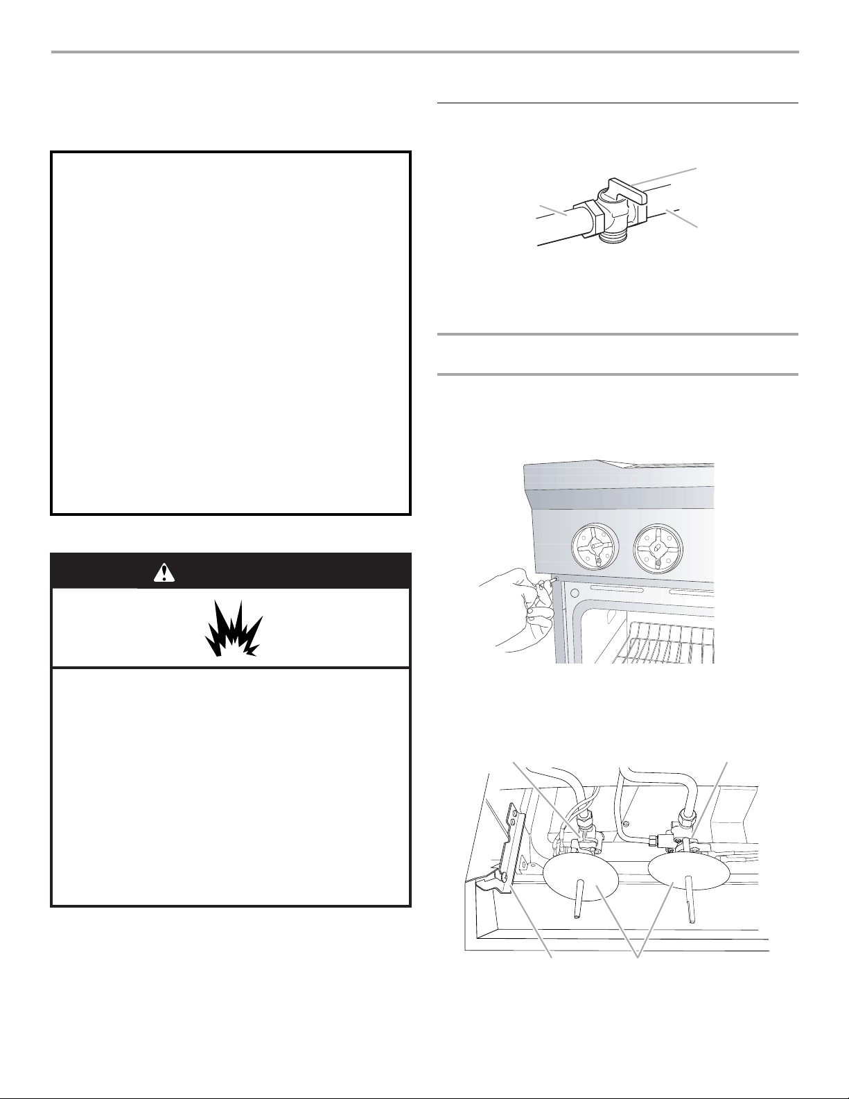
1. Remove burner grates.
2. Remove the control knobs.
3. Open the oven door and remove the 2 screws on each side of
the range that secures the console in place.
NOTE: Leave oven door ajar, or the control console will not
rest in the side brackets properly once it is detached.
4. Pull up on the control console and let it drop forward into the
notched console brackets on each side.
WARNING
This conversion kit shall be installed by a
qualified service agency in accordance
with the manufacturer's instructions and
all applicable codes and requirements of
the authority having jurisdiction. If the
information in these instructions is not
followed exactly, a fire, explosion or
production of carbon monoxide may
result causing property damage, personal
injury or loss of life. The qualified service
agency is responsible for the proper
installation of this kit. The installation is
not proper and complete until the
operation of the converted appliance is
checked as specified in the
manufacturer's instructions supplied with
this kit.
WARNING
Explosion Hazard
Use a new CSA International approved gas supply line.
Install a shut-off valve.
Securely tighten all gas connections.
If connected to LP, have a qualified person make sure
gas pressure does not exceed 14" (36 cm) water
column.
Examples of a qualified person include:
licensed heating personnel,
authorized gas company personnel, and
authorized service personnel.
Failure to do so can result in death, explosion, or fire.
A. To range or cooktop
B. Shutoff valve (closed position)
C. Gas supply line
A. Single valve
B. Dual valve
C. Control console bracket
D. Round gaskets
A
B
C
AB
DC
4
5. Remove the round gaskets from each valve stem.
6. Proceed to “Adjusting Valve Bypass Screw” section.
To Gain Access to Burner Valves on Cooktops
1. Remove burner grates.
2. Remove the control knobs.
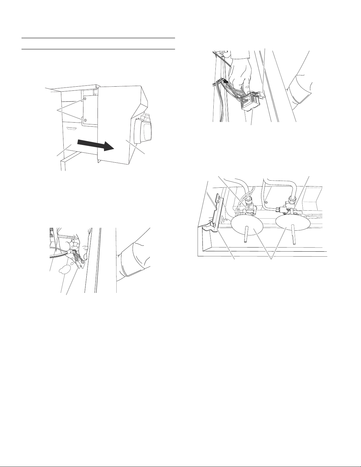
3. Pull the cooktop forward to expose the console attachment
screws on each side of the cooktop burner base.
4. Disconnect wiring from the control console.
5. On grill models only: Supporting the control console in the
middle with one arm, disconnect the grill indicator light with
the other hand.
6. On griddle models only: Supporting the control console in
the middle with one arm, disconnect the griddle switch
connectors and the grill indicator light with the other hand.
7. Remove console and set aside.
8. Remove the round gaskets from each valve stem.
9. Proceed to “Adjusting Valve Bypass Screw” section.
A. Console attachment screws
B. Control console
C. Cooktop burner base
A. Grill indicator light connector
A
B
C
A
A. Griddle switch connectors
B. Grill indicator light connector
A. Single valve
B. Dual valve
C. Control console bracket
D. Round gaskets
A
B
AB
DC

5
Adjusting Valve Bypass Screw
NOTE: The valve bypass adjustment is only required when
converting from Natural Gas to LP Gas. The bypass adjustment is
only required for single burner valves. The dual burner valves do
not require bypass adjustment because their low flame is
controlled by the burner simmer orifice.
1. Use a ¹⁄₈" x 4¼" flat-blade screwdriver to completely screw
down all single burner valves bypass screws. Do not
overtighten.
2. Reassemble range or cooktop in reverse order used when
gaining access to the burner valves.
To Convert Surface Burners
1. If installed, remove the burner grates.
2. Remove burner cap.
3. Remove the burner base.
4. Apply masking tape to the end of a 7 mm nut driver to help
hold the gas orifice spud in the nut driver while changing it.
Insert nut driver into the gas opening and press down onto
the gas orifice spud and remove by turning the gas orifice
spud counterclockwise and lifting out. Set gas orifice spud
aside.
5. Replace with correct LP gas orifice spud. See the “LP Gas
Orifice Spud/Hood Chart.”
Use the following chart to find the exact orifice spud
placement.
Fully insert choke into bottom of medium burner base. Choke
should snap into place.
Gas Orifice Spud/Hood Chart
6. Place the original gas orifice in plastic parts bag for future use
and keep with package containing literature.
7. Replace the burner base.
8. Replace burner cap.
9. Repeat steps 2 through 8 for the remaining burners.
IMPORTANT: LEAK CHECK - Refer to the “Make Gas
Connection” section of the Installation Instructions supplied
with your appliance for proper leak check procedure.
10. Plug in appliance and turn on gas supply.
IMPORTANT: Refer to the “Electronic Ignition System”
section of the Installation Instructions supplied with your
appliance for proper burner ignition, operation and burner
flame adjustments.
11. Check appliance for proper operation.
A. Gas supply tubes
B. Screws
C. Bypass screws
Large Dual Burner
A. Burner cap
B. Burner base
Medium Burner
A. Burner cap
B. Burner base
C. Choke (for use with medium
burner, LP gas only)
Small Burner
A. Burner cap
B. Burner base
BC
A
B
B
B
A
B
A
B
C
A
B
Gas
Type
Burner
Rating
(BTU)
Color Size Burner Style
LP
NG
3,000
5,000
Blue
Brass
0.55 mm
1.01 mm
Small burners
LP
NG
11,000
15,000
Brass
Brass
0.92 mm
1.55 mm
Medium burners
LP
NG
14,000
20,000
Brass
Green
Brass
Brass
0.96 mm
0.35 mm
1.80 mm
0.52 mm
Large burner - main
Large burner - simmer
Large burner - main
Large burner - simmer
LP
NG
14,500
18,000
Brass
Brass
1.07 mm
1.77 mm
Grill burner
Gas orifice spud
A. Size stamp or color
A

W10434180A
© 2011. Whirlpool Corporation.
All rights reserved.
8/11
Printed in U.S.A.

