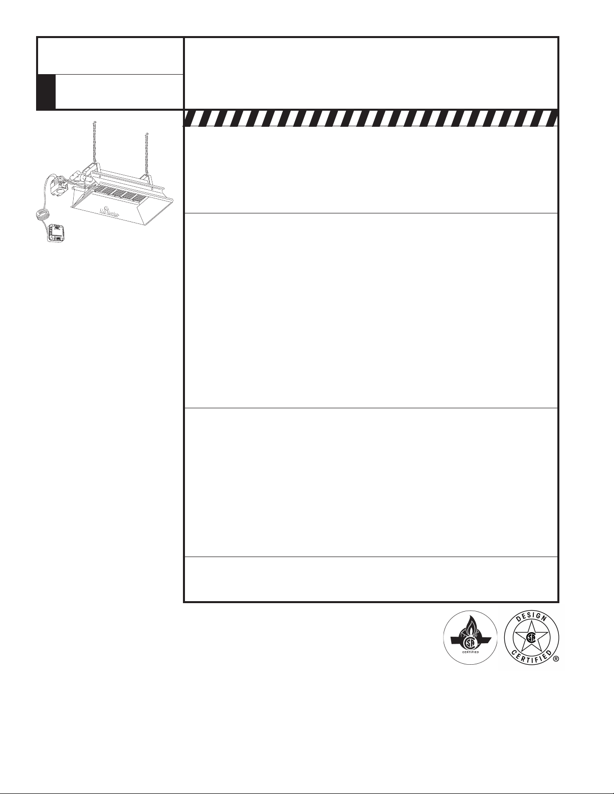
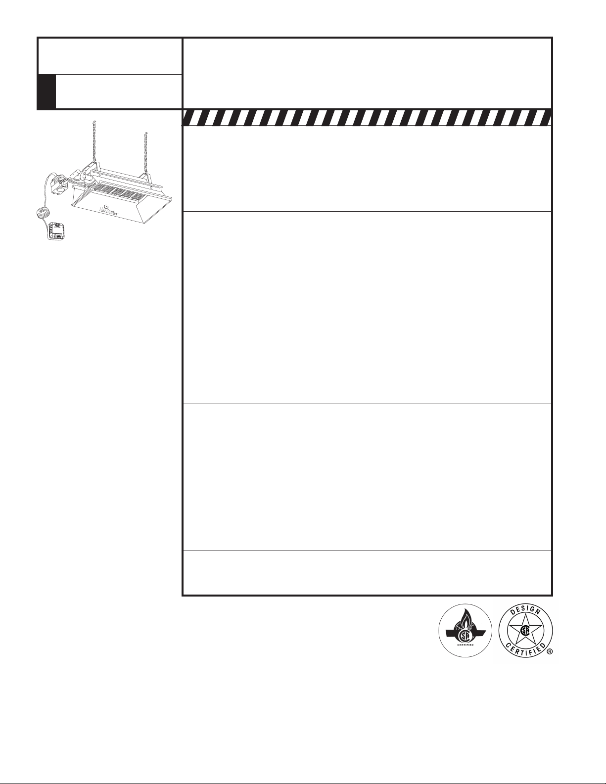
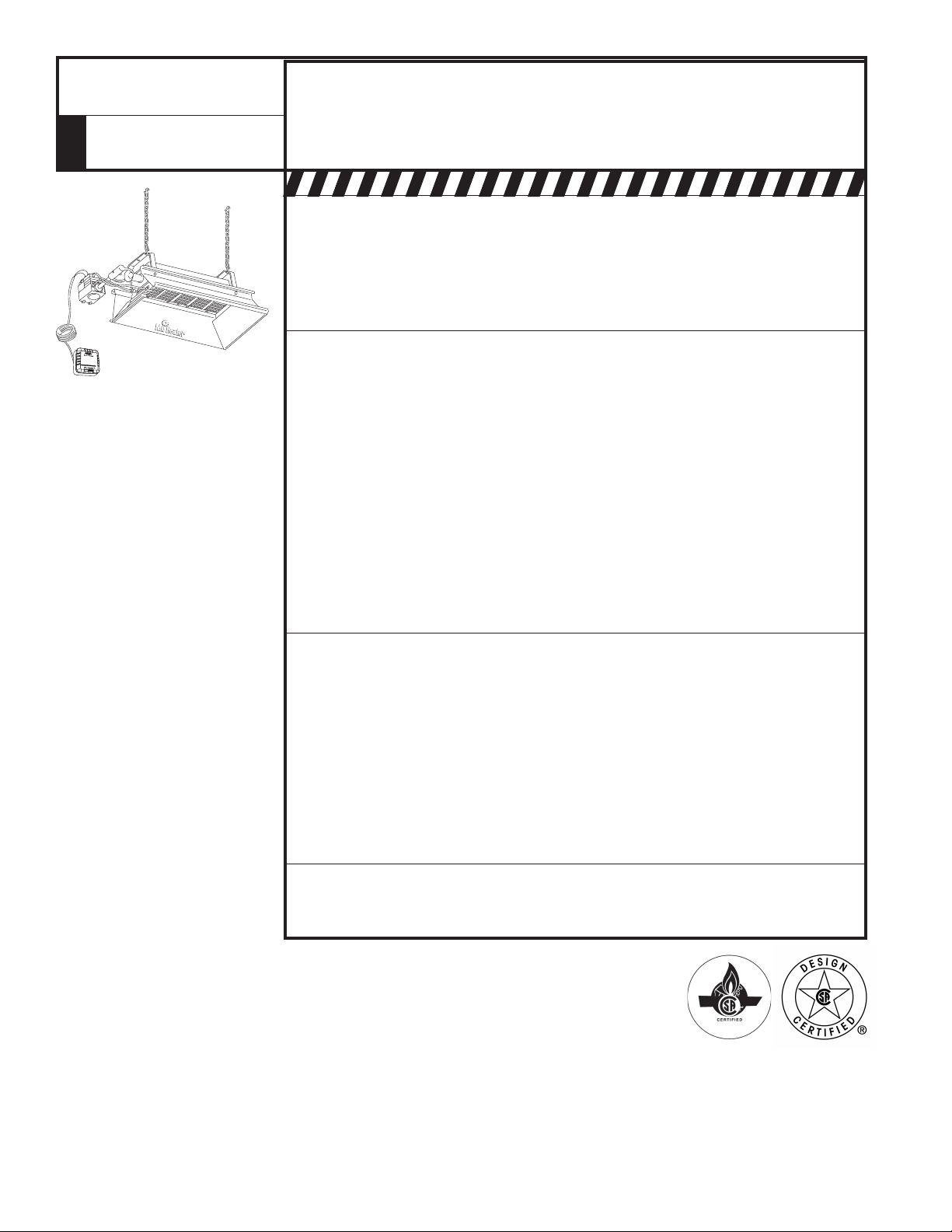
GAS FIRED INFRA-RED SPACE HEATER
Installer: Leave this manual with the appliance. Consumer: Retain this manual for future reference.
READ INSTRUCTIONS CAREFULLY: Read and follow all instructions. Place
instructions in a safe place for future reference. Do not allow anyone who
has not read these instructions to assemble, light, adjust or operate the
heater.
MH40NG
MH40LP
MODEL
OPERATING INSTRUCTIONS AND OWNER’S MANUAL
MR. HEATER
If the information in this manual is not followed exactly, a fire or explosion
may result causing property damage, personal injury or loss of life.
WARNING:
— Donotstoreorusegasolineorotherflammablevaporsandliquidsinthevicinityofthisorany
other appliance.
— WHATTODOIFYOUSMELLGAS
• Shutoffgassupply
• Donottrytolightappliance
• Donottouchanelectricalswitch;donotuseanyphoneinyourbuilding
• Immediatelycallyourgassupplierfromaneighbor’sphone.
Followthegassupplier’sinstructions
• Ifyoucannotreachyourgassupplier,callthefiredepartment
—Installationandservicemustbeperformedbyaqualifiedinstaller,serviceagencyorthegas
supplier.
Thisisanunventedgas-firedportableheater.Itusesair(oxygen)fromtheareainwhichitisused.
Adequatecombustionandventilationairmustbeprovided.Refertopage5.
18682-2017-CBENERCOGROUPINC.,4560W.160THST.,CLEVELAND,OHIO44135•216-916-3000
2
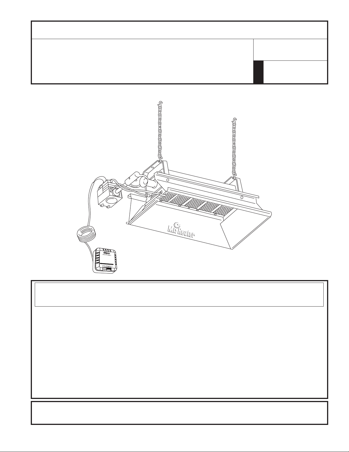
Installation Instructions and Owner’s Manual
Model # MH40NG/LP
WARNING:
Improperinstallation,adjustment,alteration,serviceormain-
tenance can cause property damage, injury or death. Read the
installation, operation, and maintenance instructions thorough-
lybeforeinstallingorservicingthisequipment.Forassistance
oradditionalinformationconsultaqualifiedinstaller,service
agency, or gas supplier.
WARNING:
Whenusedwithoutfreshair,heatermaygiveoffCARBON
MONOXIDE,anodorlesspoisonousgas.OPENWINDOWAN
INCHORTWOFORFRESHAIRWHENUSINGHEATER.
WARNING:
ThisheaterisequippedwithaPILOTLIGHTSAFETYSYSTEM.
DONOTTAMPERWITHPILOTLIGHTSAFETYSYSTEM.
WARNING:
Ifheatershutsoff,donotrelightuntilyouprovidefreshair.If
heaterkeepsshuttingoff,haveitserviced.Keepburnerand
controlclean.Opendoorfor5minutes.
MaintainclearancesasshowninFigure2oronheaternameplate.
• DONOTUSEMATCHOROTHERFLAMEFORLEAKTESTING.
• DONOTEXCEED1/2PSIINLETPRESSURETOHEATER.
DANGER:
Carbonmonoxidepoisoningmayleadtodeath.
Carbon Monoxide Poisoning:
Earlysignsofcarbonmonoxidepoisoningresembletheflu,
withheadaches,dizziness,ornausea.Ifyouhavethesesigns,
the heater may not be working properly. Get fresh air at once!
Haveheaterserviced.Somepeoplearemoreaffectedbycarbon
monoxidethanothers.Theseincludepregnantwomen,persons
with heart or lung disease or anemia, those under the influence
of alcohol, and those at high altitudes.
CAUTION:
• Neverconnectgasvalveorthermostattolinevoltageora
transformer.
• Iftheinfra-redcolorofthegridbecomesdullwhenthebuild-
ing furnace is operating, consult gas supplier on correct gas
supply piping sizes.
• Thisheaterisforindoorinstallationonly!
NOTE
Gasket binder material used in this heater assembly will
temporarilyemitanodorand/orvapor.Thisconditionwillclearup
inapproximately20minutesandthereafterwillnotreoccur.Refer
toChapter9forventilation.
TABLE OF CONTENTS
1.GENERALINFORMATION ........................................................ 3
2.CLEARANCES .......................................................................... 3
3.SUSPENSION .......................................................................... 4
4.GASSUPPLY............................................................................ 4
5.PIPINGREQUIREMENTS .......................................................... 4
6.GASPRESSURE ....................................................................... 4
7.ELECTRICAL ............................................................................. 4
8.THERMOSTAT&LOCATION ..................................................... 4
9.VENTILATION .......................................................................... 5
10.START-UPPROCEDURE .......................................................... 5
11.HEATERSHUTDOWN ............................................................. 5
12.OPERATORMAINTENANCEINSTRUCTIONS ........................... 5
13.REPLACINGTHEGASVALVEUNIT ......................................... 7
14.FREQUENCYOFOPERATORCHECKS ..................................... 7
15.REPLACEMENTPARTSLIST .................................................... 7
16.WARRANTY ........................................................................ 8
THE STATE OF CALIFORNIA REQUIRES THE
FOLLOWING WARNING:
WARNING:
Combustionby-productsproducedwhenusingthisproductcon-
taincarbonmonoxide,achemicalknowntotheStateofCalifornia
tocausecancerandbirthdefects(orotherreproductiveharm).
3
Installation Instructions and Owner’s Manual
Model # MH40NG/LP
1. GENERAL INFORMATION
a. Yourheatercomesfullyassembledandistestedatthefactory
for proper gas and input as stated on the name plate.
b. Beforeproceedingwiththeinstallation,besuretoinspectfor
damages.Freightcompanymustbenotifiedofanydamages
andrequestthattheinspectionbemade.MR.HEATERwill
sendreplacementpartsfordamagedpartsonlyafterreceiving
asignedinspectionreporttoprovetheliabilityofthefreight
company.
c. Do not attempt to operate heater with any other gas than that
indicated on the heater name plate.
d. Theinstallationofheatermustconformwithlocalbuilding
codes,orinabsenceoflocalcodes,withtheNationalFuelGas
Code,ANSIZ223.1a/NFPA54,andStandardforStorageand
HandlingofLiquefiedPetroleumGases,ANSI/NFPA58.
e. CanadianinstallationsmustcomplywithCAN/CGA-B149.1.2
GasCodewhichcanbepurchasedfromtheCSA(Canadian
StandardsAssociation)website@http://www.csa.caorby
calling1-800-463-6727.
f. Plugged1/8”N.P.T.TestGageConnectionislocatedonthe
HeaterGasValveora¼”N.P.T.Connectionislocatedonthe
outsideoftheCastVenturi.
g. Contactthefactorywhenapplianceistobeinstalledathigh
altitudes.Factorysupplieshigh-altitudeconversionkitswith
instructions and data plates.
For additional information, contact;
MR.HEATERCORPORATION
CUSTOMERSERVICEDEPT.
CLEVELAND,OHIO
1-800-251-0001
*ThefollowingextraNFPAmanualsarehelpfulwheninstalling
MR.HEATERinalocationnotanticipatedinthismanual:
Number Related Subject
NFPA88 ClearancestoCombustibleSurfaces
NFPA409 ClearancestoCombustibleSurfaces
DONOTEXCEED½PSIINLETPRESSURETOHEATER
2. CLEARANCES
Minimumclearancestocombustibles(RefertoTable3)..Also
betweencontrolendofheaterforservicingandminimumontop
andsidesforventilationandcombustionairsupply.
Aminimumclearanceof8’abovefloorforpublicgaragesin
accordancewithANSI/NFPANo.409mostrecentedition,orTable
3;thelargerdimensionofANSI/NFPANo.409orTable3istobe
used.
*WhenselectinginstallationlocationsforMR.HEATERensurethat
theopeningofanyexteriororinteriordoorsorwindowswillnot
violateclearancesorcontactanyheatercomponents.
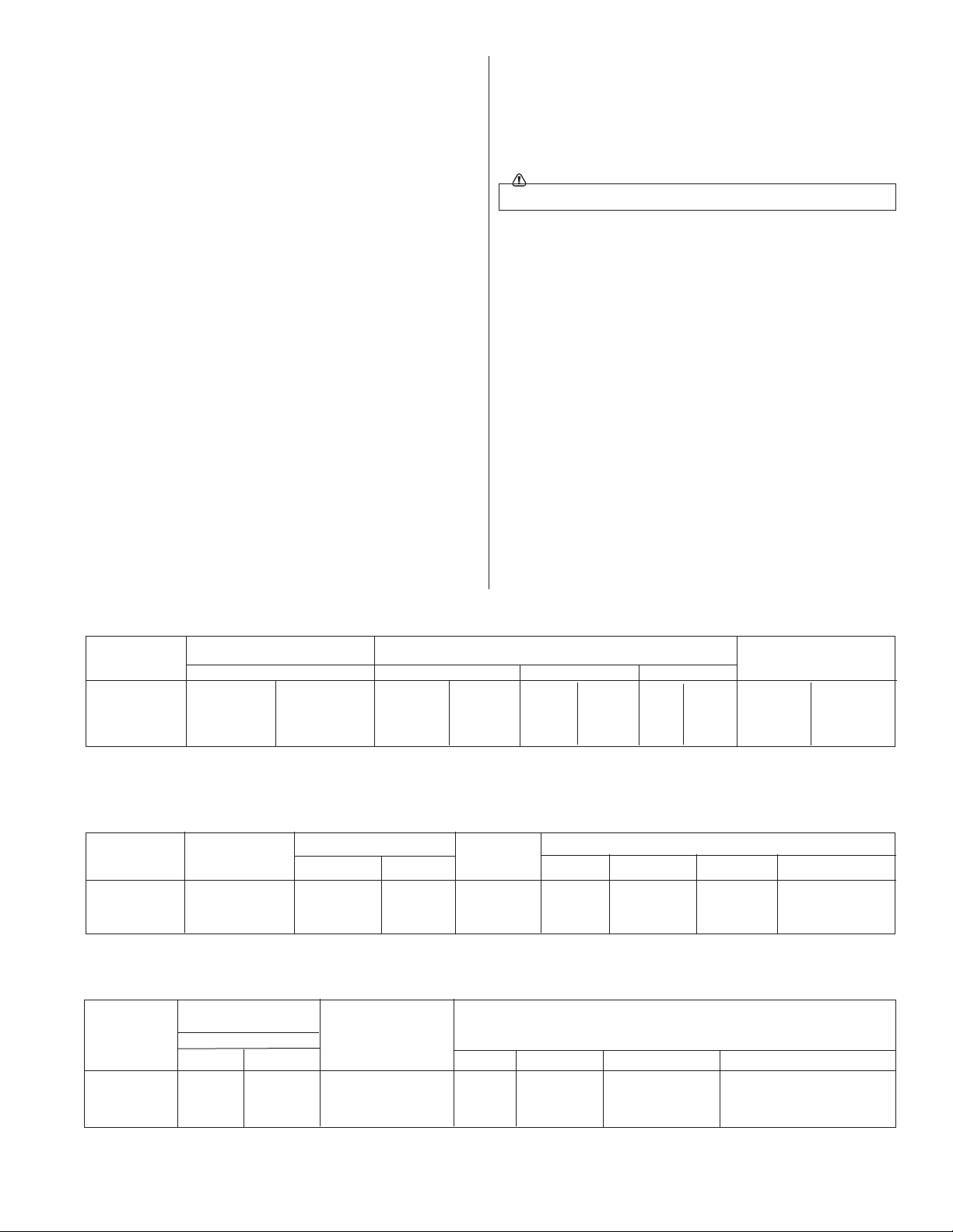
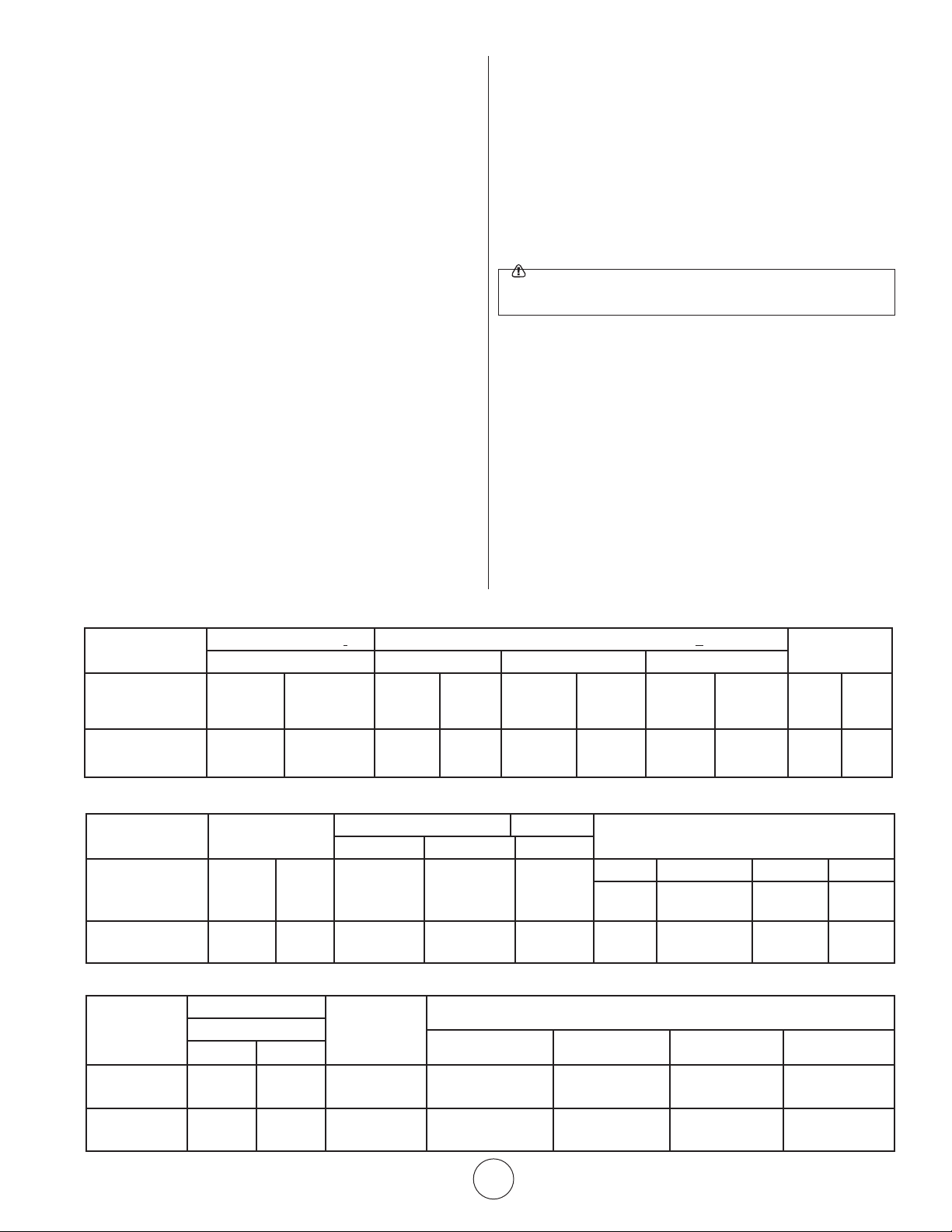
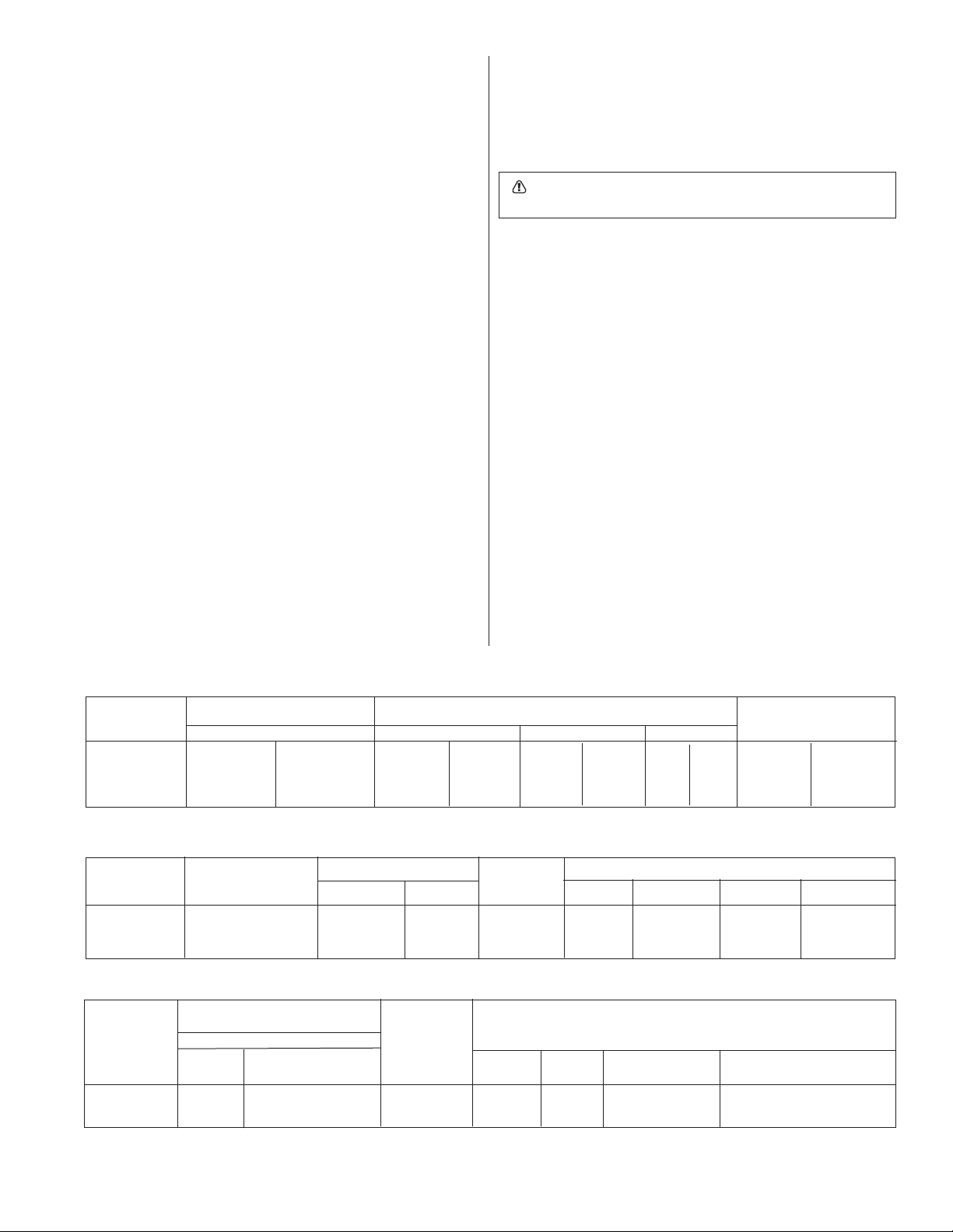
Table 1. BTU Ratings and Supply Pressures
MODEL BTU/HR. RATING GAS SUPPLY PRESSURE (W.C.) ORIFICE
NO. GAS MIN. MAX. MANIFOLD SIZE
NATURAL PROPANE NAT. L.P. NAT. L.P. NAT. L.P. NAT. L.P.
MH/HS40NG 40,000 — 6.8” W.C. — 7” W.C. — 5.8” — 37 —
MH/HS40LP — 40,000 — 11” W.C. — 14” W.C. — 10” — 50
Table 2. Heater Dimensions and Orice Sizes
MODEL OPERATING ORIFICE SIZE INPUT SIZE
NO. PRESSURE BURNER PILOT BTU/H WIDTH LENGTH HEIGHT WEIGHT
MH/HS40NG 6.8”w.c. 37 .023 40.000 19-1/4” 30-1/4” 12” 25 lbs.
MH/HS40LP 10”w.c. 50 .015 40,000 19-1/4” 30-1/4” 12” 25 lbs.
Table 3. Installation, Ventilation and Mounting Information
BTU/HR. RATING NORMAL
MODEL GAS MOUNTING CLEARANCES TO COMBUSTIBLE SURFACES
NO. NAT. L.P. POSITION TOP SIDES BACK BELOW
MH/HS40NG 40,000 — HORIZ-30˚ 34” 30” 30” 68”
MH/HS40LP — 40,000 HORIZ-30˚ 34” 30” 30” 68”
4
Installation Instructions and Owner’s Manual
Model # MH40NG/LP
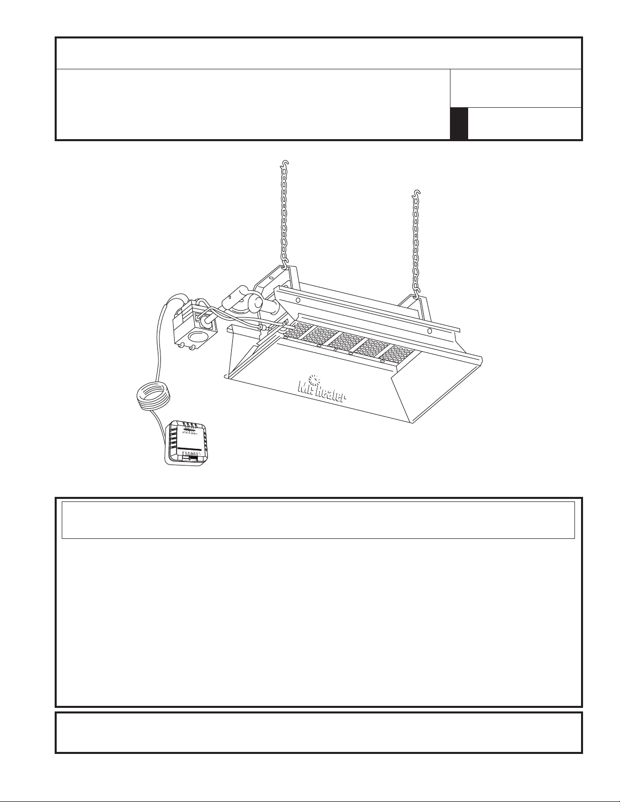
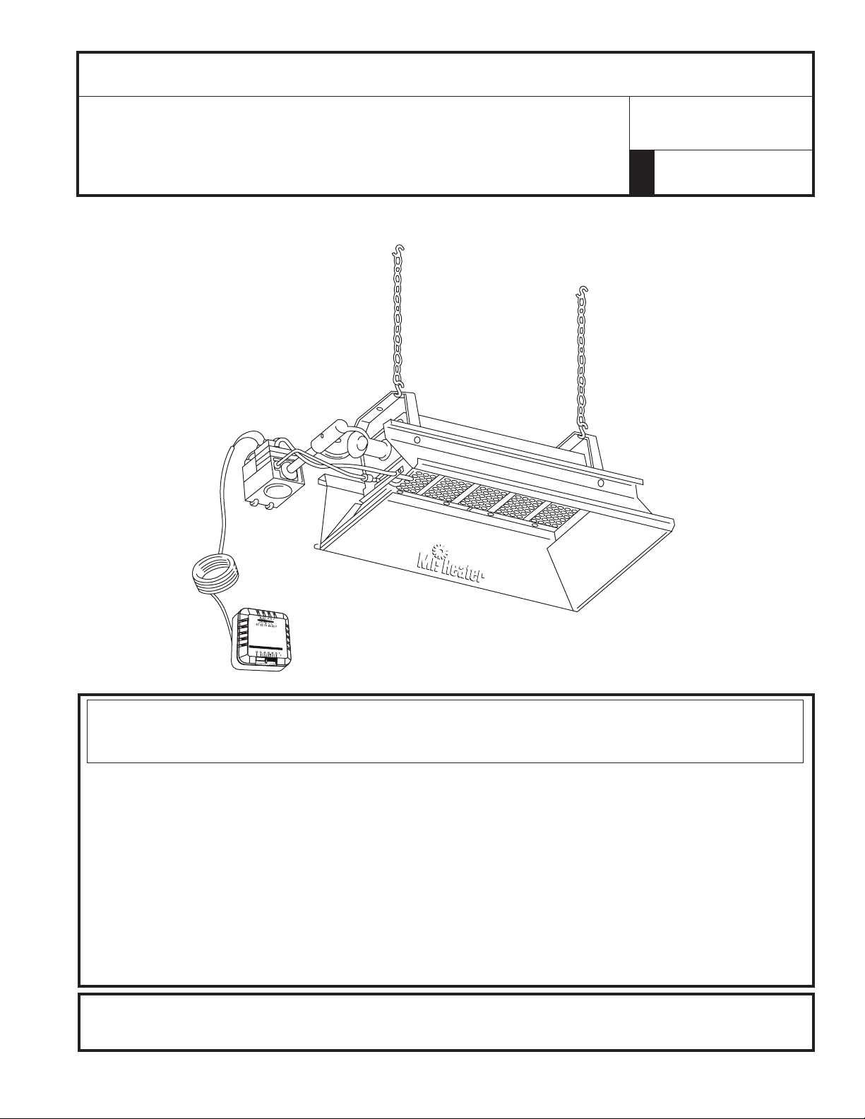
3. SUSPENSION
Heater has four mounting holes, two on each end, for attaching
rod, chain, or angle iron brackets and shall be safely and
adequatelyfixedinpositionindependentofgasandelectricsupply
lines.
4. GAS SUPPLY
Provideadequategassupplyforratedinputofeachheaterusing
AmericanStandardInstallationofgaspipingandgasappliances
inbuilding.ANSIZ223.1a/NFPA54pamphlet,TableC-3shows
capacity of pipe of different diameters and lengths in cubic feet
perhournaturalgaswithpressuredropof0.3inches,specific
gravityof0.60.ForliquefiedPetroleumGas(LP)capacityrefer
toFigures3.Onthreadedpipesuseapipecompoundwhichis
resistant to the action of all gases.
Ifgaslinesaretobepressuretestedwithcompressedair,
disconnecteachheatertopreventcontroldamageandcap
outlets.Afterreconnectingallheaters,purgegaslinesofair
andcheckallconnectionsforleaksusingsoapsolution.Liquid
dishwashingdetergentisanexcellentleakdetector.
5. PIPING REQUIREMENTS
Allpipinginstalledmustcomplywithlocalcodesandordinances
orwiththeNationalFuelGasCode,ANSIZ223.1(NFPA54),
whichevertakesprecedence.Wheninstallingpiping,thefollowing
requirementsmustbetakenintoconsideration:
• Usenewproperlyreamedblackpipefreefromchips.
• Applyagoodqualitypipecompoundtoallmalethreadsprior
toassembly.IfL.P.gasisthefuel,ensurethatpipecompound
isresistanttoL.P.gas.DONOTUSETEFLON™tape.
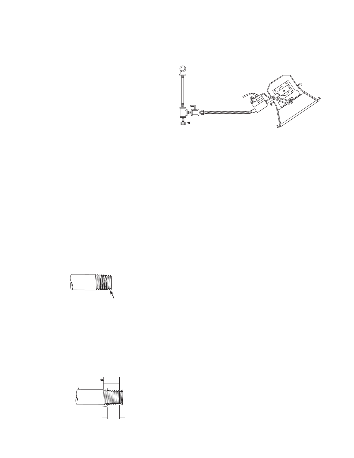
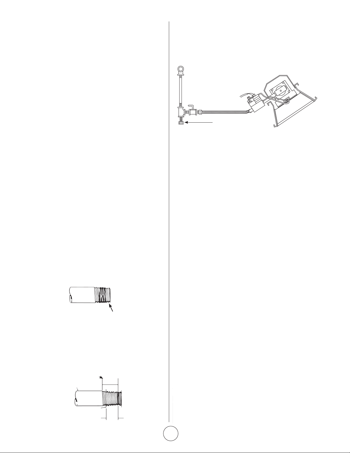
• Priortoinstallation,applypipecompoundtoallmalethreads
asshowninFigure1.
USE MODERATE AMOUNT OF PIPE DOPE
LEAVEFIRST2THREADSBARE
Figure 1. Pipe Compound Application
• Malethreadsonpipetobeinstalledintogasvalveshallmeet
therequirementsofFigure2.Threadslongerthanthose
showninthefiguremaycausegasvalvedistortionandmal-
function.
• AsedimenttrapmeetingthetypicalrequirementsofFigure3
shallbeinstalledinthelinetothegasvalve.
• Adedicatedshutoffvalvefortheheatermustbeinstalledin
¾”MAXIMUMTHREADLENGTH
½”BLACKPIPE
GASVALVEBODY
½”MAXIMUMDEPTHOFINSERTS
INTOGASVALVE
the gas supply line.
NOTE:
1.OnlyUseAPipeCompoundWhichIsResistantToLiquefied
GasesOnL.P.Installations.
2.FittingsShownAreNotIncludedWithHeater.
Figure 3. Typical Piping Installation
6. GAS PRESSURE
Whenahigherthanthemaximumrecommendedgaspressureis
being maintained at the main gas line, a separate regulator must
beinstalledaheadoftheheater.RefertoTable1onpage3for
maximumallowablepressureforstatedheatermodelandgas.
Seeheaterratingplateforminimumgassupplypressure“Forthe
PurposeofInputAdjustment.”
On a multiple heater installation in may be possible to use one
largecapacityregulatororanindividualregulatorforeachheater.
Nevertheless,itisrecommendedpracticetomaketheentirepipe
system a loop.
Contactyourlocalrepresentativeorthefactoryforpropergas
pressure reducing design stage.
7. ELECTRICAL
NEVERCONNECTPOWERPILEGASVALVEORTHERMOSTATTO
LINEVOLTAGEORATRANSFORMER.
8. THERMOSTAT & LOCATION
Make sure that the electrical characteristics of the thermostat
matchthoseoftheheatercontrols.Forbestresultsthermostat
shouldbepositioned5ft.abovefloorwhereaircancirculate
freely around it. DO NOT MOUNT directly to cold-side wall, in
direct drafts, or directly beneath the infra-red heater.
Ensure that the selected thermostat location meets all of the
aboverequirements.Refertotheinstructionsthatcomewith
the thermostat for additional general information and mounting
instructions.
Ifthewallisofstudandwallboardconstruction,thenusethe#6
by 1 inch sheet metal screws, included with the thermostat, and
mount the thermostat in the selected location.
Ifwallisbrickormasonry,theappropriateanchorsmustbe
obtainedtoaccommodatethethermostatmountingscrews.Use
the back plate of the thermostat as a template to mark the hole
location, drill appropriate size anchor holes, install the anchors and
securely attach the thermostat using the mounting screws.
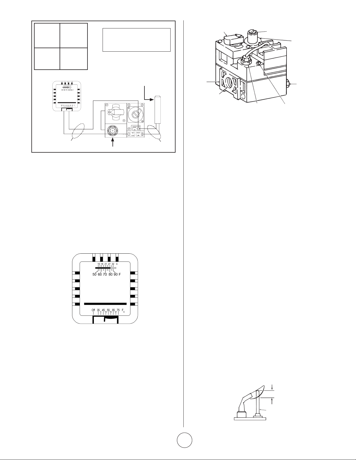
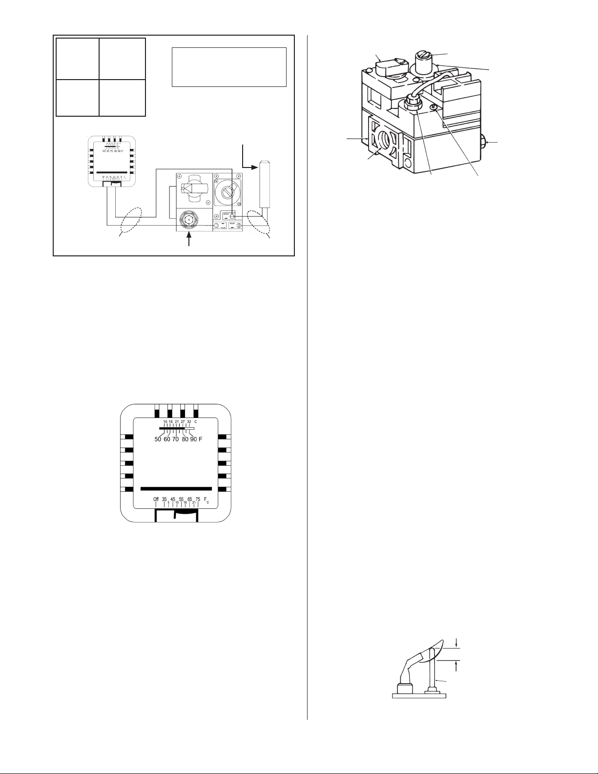
ConnectthethermostatwirestogasvalveasshowninFigure4.
Figure 4 connection diagram
Figure 2.
Gas valve
connection
requirements
Sedimenttrap

5
Installation Instructions and Owner’s Manual
Model # MH40NG/LP
9. VENTILATION
a. Theminimumintakeandexhaustairopeningsshallprovide
fornotlessthan400CFMforevery100,000BTUinputexcept
that the infiltration area may be included in the intake area.
b. Wherenatural(gravity)ventilationisprovidedforexhaust,the
openingsmustbedistributedabovetheheaters(preferablyat
thepeakoftheroof)andtheareasofopeningsshallnotbe
lessthan300squareinchesforevery100,000BTUinput.
10. START-UP PROCEDURE
OPENTHEGASSUPPLYVALVEORVALVES.
Figure 5. Thermostate controls
SetthethermostattotheOFFposition.SeeFigure5.Ifthe
manualgascontrolknobonthegasvalveisnotintheOFF
position,partiallydepresstheknobandrotatetotheOFFposition.
SeeFigure6.
Wait5minutestoallowgasthatmayhaveaccumulatedinthe
mainburnertoescape(especiallyimportantafterinstallation).
TurnthemanualgascontrolknobtothePILOTposition.
Depressthemanualgascontrolknob.Usingamatch,lightthe
pilotlight.SeeFigure6.Holdtheknobdownforapproximately
30secondstoallowanyairingaslinestopassthroughpilotand,
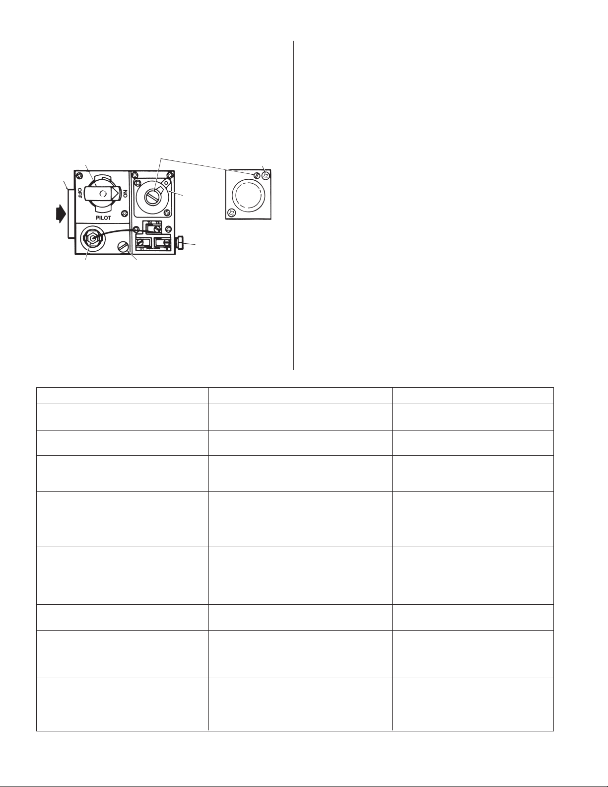
MANUALGAS
CONTROLKNOB
WRENCH
BOSS
GASINLET
PRESSUREREGULATOR
ADJUSTMENT
STANDARD
PRESSURE
REGULATOR
(Incoming pressure
not exceed 13” W.C.)
PILOTGAS
OUTLET
(PRESSURE
TAPPING
DIRECTLY
BENEATH)
PILOTFLOW
ADJUSTING
SCREW
(BENEATH
COVERSCREW)
PILOTSTATPOWER
UNIT
Figure 6. Gas Valve
Components
once the pilot is lit, allow the thermocouple to heat up enough to
activatethesafetyvalveinanopenposition.
Release manual gas control knob and turn to ON. Reset
thermostat to desired temperature.
NOTE:
DuringtheinitialstartupofMR.HEATERanodorand,perhaps,
somevaporwillcomefromtheheater.Thisisthegasketbinding
materialemittingthisodorand/orvapor.Afterapproximately20
minutes this odor will disappear and not occur again.
11. SHUTDOWN
1. TurnthermostattoOFF.
2. TurnmanualgascontrolknobongasvalvetoPILOTposition.
3. PartiallydepressknobandrotatetotheOFFposition.
4. Closegassupplyvalves.
12. OPERATOR MAINTENANCE
INSTRUCTIONS
1. TROUBLESHOOTING
a. Table4liststhecommonmalfunctionswhichyoumayfind
during the operation or maintenance of your heater.
b. ForadditionalinformationrefertoHoneywellFieldBulletin
enclosed in the heater carton.
c. Intheevent,resultscannotbeobtainedafterperformingall
listed solutions, call your Mr. Heater dealer, or the factory
customerservicedepartmentat1-800-251-0001.
2. ADJUSTING THE PILOT FLAME
Thepilotflameshouldenvelope3/8to½in.(10to13mm)ofthe
THERMOCOUPLE
PROPERFLAMEADJUSTMENT
3/8TO½INCH
(10TO13MILLIMETERS)
Figure 7. Proper flame adjustment
POWERPILEGASVALVE
POWERPILEGENERATOR
WIRE
SIZES
MAXIMUM
LENGTH
2WIRE
CABLE
NO. 18
NO. 16
NO. 14
15FEET
30FEET
50FEET
CAUTION:
Neverconnectpowerpilegas
valveorthermostattolinevoltage
or a transformer
FactoryWired
ThermostatWires
6
Installation Instructions and Owner’s Manual
Model # MH40NG/LP
tipofthethermocoupleorgenerator.Toadjustthepilotflame,
refertoFigure7.
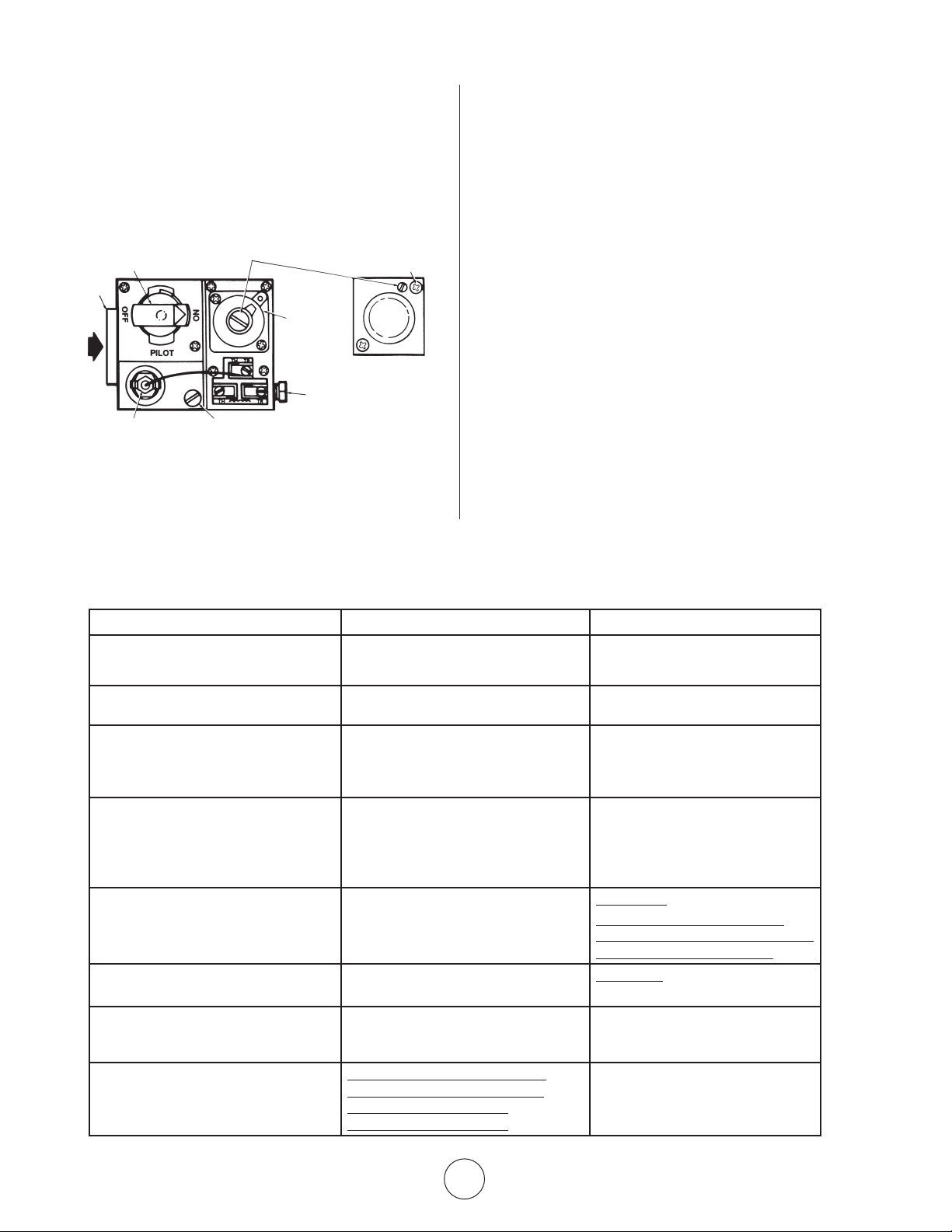
a. Removepilotadjustmentcoverscrew.RefertoFigure8.
b. Turninneradjustmentscrewclockwisetodecreaseorcounter-
clockwise to increase pilot flame.
c. Alwaysreplacecoverscrewafteradjustmentandtightenfirmly
to ensure proper operation.
Manual gas
control knob
Wrench
boss
Gas
inlet
Pilotstat
power unit
Pressure regulator
adjustment(beneath
coverscrew)
Installlong
screw in
outside corner
Standard
pressure
regulator
(“A”model)
Step
opening
regulator
(“C”model)
Pilot gas
outlet
(pressure
tapping
directly
beneath)
Pilot flow adjusting screw
(beneathcoverscrew)
Figure 8. Top view of standard capacity gas control.
TABLE 4. TROUBLESHOOTING CHART
Belowinchartformarevarioussymptomsofamalfunctioning
system, possible defects that will cause there symptoms and
suggestedcorrectivemeasure.Thechartassumesthattheproper
gaspressureisavailabletotheheaterandthatthelighting
procedure is as stated on the plate attached to the heater.
SYMPTOMS CAUSES SOLUTIONS
Burnerlightoffveryslow Partiallyblockedpilotorifice Re-adjustpilot
Pilot out of adjustment Replace
Burnerlightoffveryslowly Partiallyblockedburnerorifice Replace
Colorstaysdull
Burnerflashback Lowgaspressure Correctlinepressureorcallyourgas
(roaringnoiseduringoperation supplier
andceramicgridsurfacewillbedark) Damagedburner Replace
Ceramicgridorburnersootingup
(whenneworaftercleaning) Firstcheckfordamaged Replaceifdamaged
burner orifice
Ifburnerorificeisnotdamaged
then check for damaged manifold. Replace
Pilotcannotbeignited Blockedpilotorifice Replace
Gas cock not in position
Pilot gas flow adjustment screw may be closed Gas control knob must be turned to pilot
and held depressed
Openandadjust(seeFigure8)
Pilotlightsbutgoesout Defectivethermocouple Replace
Defectivecontrol Replace
Pilotstayslitbutmainburnerwillnotlight Loosewireorimproperlywired Tightenconnections,checkwiring
Defectivecontrol diagram
Blockedburnerorifice Replace
Cleanorificeorreplace
Failuretoignite Maingasoff Openmanualvalves
Airingasline Bleedgasline
Loosewireconnections Tightenwireconnections
Dirtywireconnections Cleanterminalsandsecureterminals
13. REPLACING THE GAS VALVE UNIT
a. Removethetwogasvalveunitwiresatthegascontrolvalve
labeled“PP.”
b. Unscrewgasvalvefromgaspiping.
c. Reconnectgasvalveandunitwirestoterminals“PP.”Besure
toleavethermostatwireononeterminal.
14. FREQUENCY OF OPERATOR CHECKS
Intermittent Use
Appliancesthatareusedseasonallyshouldbecheckedbefore
shutdownandagainbeforethenextuse.
Dusty,wetorcorrosiveenvironment.Sincetheseenvironments
can cause the gas control to deteriorate more rapidly, the system
should be checked more often.
The gas control should be replaced if:
a. Itdoesnotperformproperlyoncheckoutortroubleshooting.
b. Thegascontrolknobishardtoturnorpushdown,oritfails
to pop back up when released.
7
Installation Instructions and Owner’s Manual
Model # MH40NG/LP
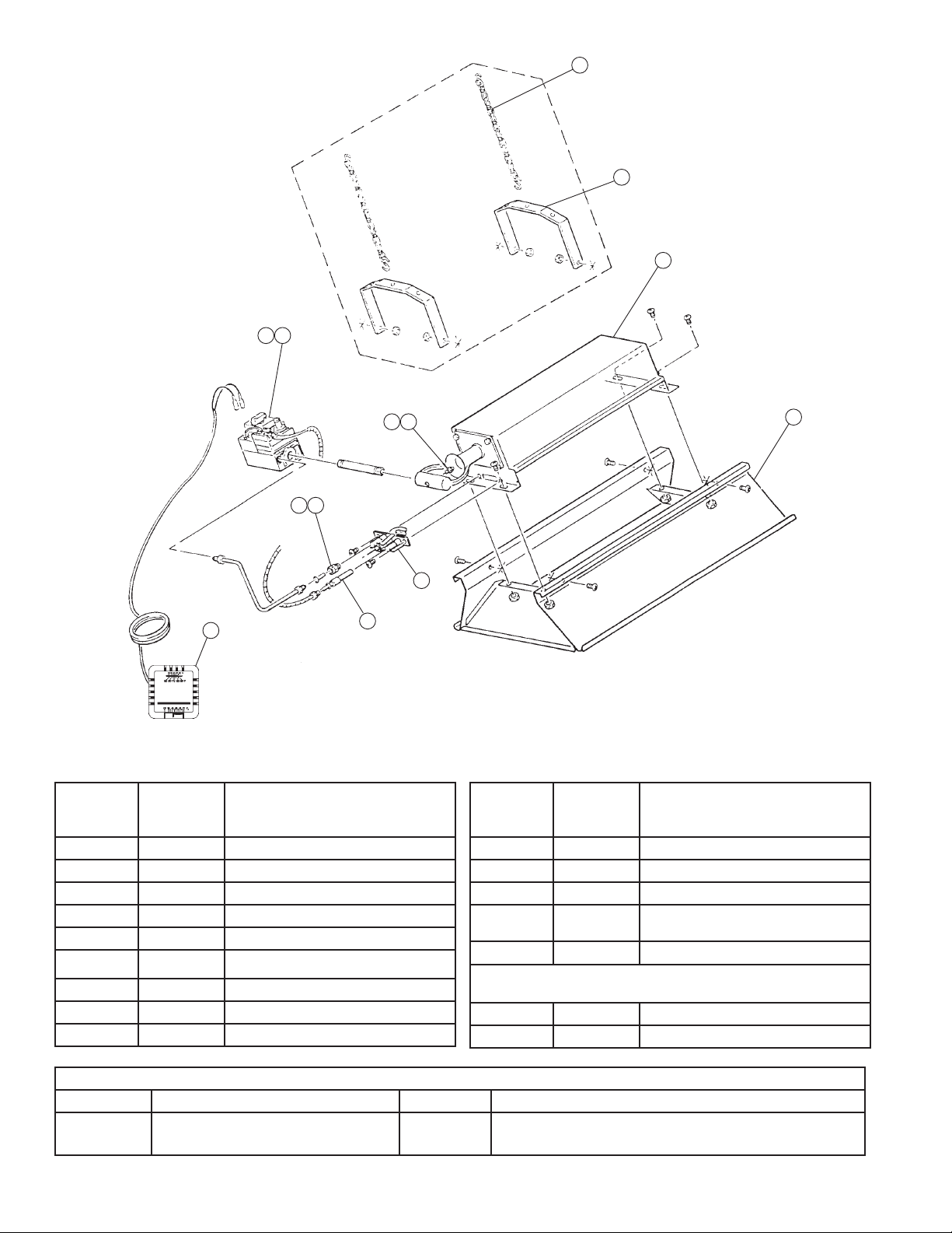
1 2
5 6
10
9
11
7 8
12
13
4
3
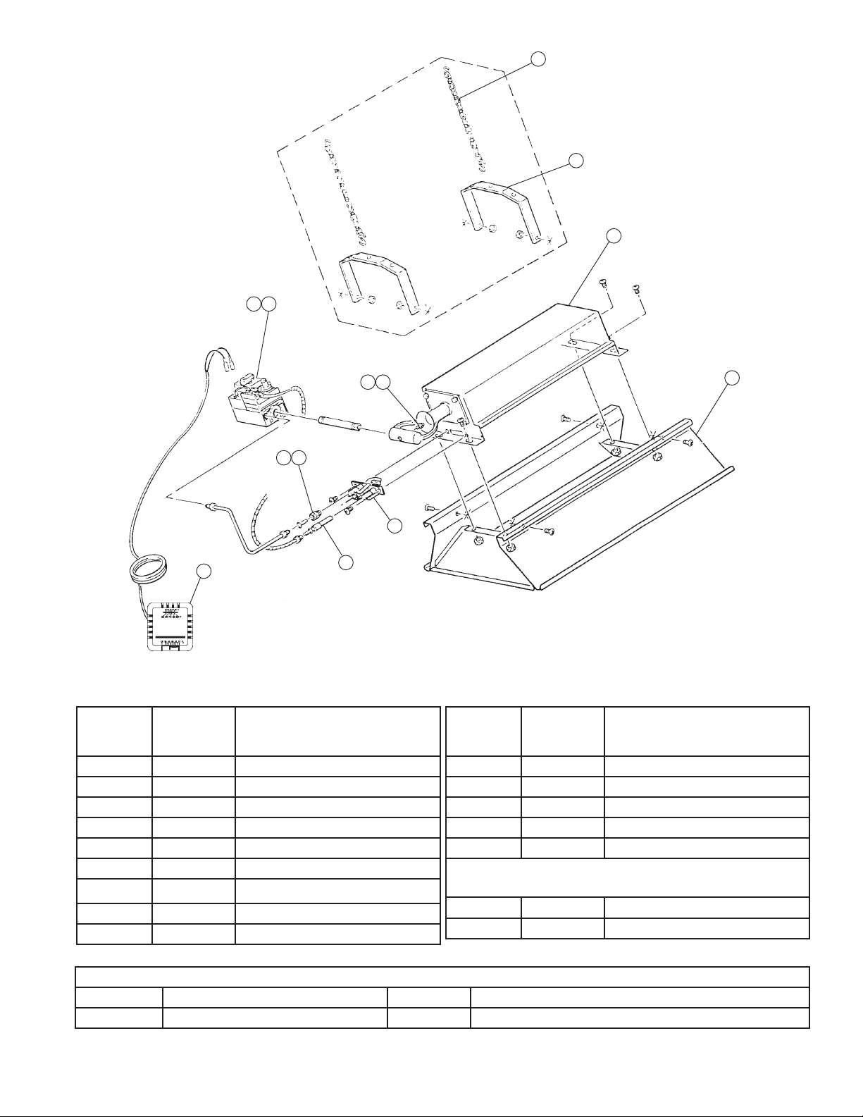
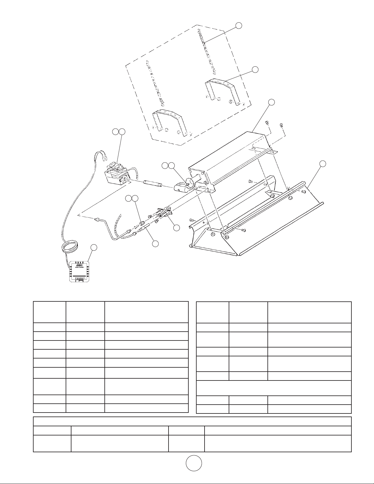
ITEM NO STOCK NO DESCRIPTION
1 00024 GAS-VALVE-NATURALGAS
2 00025 GASVALVE-PROPANEGAS
3 00434A REFLECTORASSEMBLY
4 02523A BURNERASSEMBLY
5 05574 ORIFICE–PILOTNATURALGAS
6 05573 ORIFICE–PILOTPROPANEGAS
7 05450 ORIFICEBURNER-PROPANEGAS
8 05437 ORIFICE–BURNERNAT.GAS
9 09360 THERMOCOUPLE-GENERATOR
ITEM NO STOCK NO DESCRIPTION
10 10367 THERMOSTAT
11 11406 PILOTBURNERNATURALGAS
12 17374 CHAINKIT
13 F114581 HEATERHANGERKIT
14 114 0 5 PILOTBURNERL/P
OPTIONAL CONVERSION KITS:
……… 00286A LPtoNGConversion
……… 00285A NGtoLPConversion
MH40 REPLACEMENT PARTS LIST
OPTIONAL DECORATIVE GRID KIT
STOCK NO. DESCRIPTION STOCK NO. DESCRIPTION
F204440 GridKit(Grid,Screws,RetentionClip) F204441 RetroFitGridKit(Reflector,Grid,Screws,RetentionClip)
8
Installation Instructions and Owner’s Manual
Model # MH40NG/LP
EnercoGroup,Inc.reservestherighttomakechangesatanytime,withoutnoticeor
obligation, in colors, specifications, accessories, materials and models.
WARNING:
USEONLYMANUFACTURER’SREPLACEMENTPARTS.USEOFANYOTHERPARTS
COULDCAUSEINJURYORDEATH.REPLACEMENTPARTSAREONLYAVAILABLE
DIRECTFROMTHEFACTORYANDMUSTBEINSTALLEDBYAQUALIFIEDSERVICE
AGENCY.
PARTS ORDERING INFORMATION:
PURCHASING: AccessoriesmaybepurchasedatanyMr.Heaterlocaldealeror
direct from the factory
FOR INFORMATION REGARDING SERVICE
PleasecallToll-Free800-251-0001
www.mrheater.com
Ourofficehoursare8:00AM–5:00PM,EST,MondaythroughFriday.
Please include the model number, date of purchase, and description of problem in
all communication.
LIMITED WARRANTY
EnercoGroup,Inc.warrantsitsheatersandaccessoriestobefreefromdefectsin
material and workmanship for a period of 1 year from date of purchase. Enerco
Group,Inc.willrepairorreplacethisproductfreeofchargeifithasbeenproven
tobedefectivewithinthe1-yearperiod,andisreturnedatcustomerexpensewith
proofofpurchasetoEnercoGroup,Inc.withinthewarrantyperiod.
OPERATING INSTRUCTIONS
AND OWNER’S MANUAL
ENERCOGROUP,INC.,4560W.160THST.,CLEVELAND,OHIO44135•216-916-3000
Mr.HeaterandPortableBuddyareregisteredtrademarksofEnercoGroup,Inc.
©2017,Enerco/Mr.Heater.Allrightsreserved
ANSI Z83.19a-2002
CSA 2.35a-2002
®
MH40NG
MH40LP
MODEL
MR. HEATER
ALENTADOR INFRARROJO A GAS PARA TALLERES
Instalador: deje este manual junto con el artefacto. Consumidor: conserve este manual para referencia futura.
LEA CUIDADOSAMENTE LAS INSTRUCCIONES: lea y siga todas las
instrucciones.Conserveestasinstruccionesenunlugarseguroparafutura
referencia.Nopermitaquenadiequenohayaleídoestasinstrucciones
arme, encienda, ajuste o use el calentador.
MH40NG
MH40LP
MODEL
INSTRUCCIONES DE USO Y MANUAL DEL USUARIO
MR. HEATER
Si no se siguen al pie de la letra las instrucciones de este manual, podría
producirse un incendio o una explosión que provocaría daños materiales,
lesiones o muertes
ADVERTENCIA:
— NoalmaceneniutilicegasolinaniningúnotrovapornilÃquidoinflamablecercadeestenideningúnotro
artefacto.
—QUÉHACERSIDETECTAOLORAGAS
• Cierreelsuministrodegas.
• Nointenteencenderelartefacto.
• Notoqueningúninterruptoreléctrico;nouseelteléfonodentrodeledificio.
• Llameinmediatamentealproveedordegasdesdeelteléfonodeunvecino.
Sigalasinstruccionesdelproveedordegas
• Sinopuedecomunicarseconelproveedordegas,llamealdepartamentodebomberos
—Lainstalaciónylasreparacionesdebenserrealizadasporuninstalador,unaagenciadereparaciónoun
proveedordegascalificados
Estecalentadorportátilagasnotieneunafuentepropiadeventilación.Utilizaelaire(oxígeno)deláreaenla
cualseemplea.Debesuministrarseelairenecesarioparalaventilaciónylacombustión.Consultelapágina5.
18682-2017-CBENERCOGROUPINC.,4560W.160THST.,CLEVELAND,OHIO44135•216-916-3000
2
Instrucciones de uso y manual del usuario
Modelo # MH40NG/LP
ADVERTENCIA:
Lainstalación,elajuste,laalteración,lasreparacioneso
elmantenimientoinadecuadospuedenprovocardañosmateriales,
lesiones o muertes. Lea cuidadosamente las instrucciones de
instalación,usoymantenimientoantesdeinstalaroreparareste
equipo.Paraobtenerasistenciaoinformaciónadicional,consulte
conuninstalador,unaagenciadereparaciónounproveedorde
gas calificados.
ADVERTENCIA::
Cuandoseutilizasinairefresco,esposiblequeelcalentadordes-
pidaMONÓXIDODECARBONO,ungasvenenosoinodoro.ABRA
LAVENTANAUNAODOSPULGADASPARAQUECORRAAIRE
FRESCOCUANDOUTILICEELCALENTADOR.
ADVERTENCIA::
EstecalentadorestáequipadoconunSISTEMADESEGURIDAD
DEENCENDIDODELPILOTO.NOMODIFIQUEELSISTEMADE
SEGURIDADDEENCENDIDODELPILOTO.
ADVERTENCIA::
Sielcalentadorseapaga,novuelvaaencenderlosinantesdejar
correrairefresco.Sielcalentadorsigueapagándose,hágalorepa-
rar.Mantengaelquemadoryelcontrollimpios.Abralapuerta
durante5minutos.
Mantengadistancia,comosemuestraenlaFigura2oenlaplacadel
calentador.
• NOUTILICEFÓSFOROSNININGUNAOTRALLAMAPARA
VERIFICARLASFUGAS.
• NOEXCEDALOS3,44kPa(1/2PSI)DEPRESIÓNDEENTRADAAL
CALENTADOR.
PELIGRO:
Laintoxicaciónconmonóxidodecarbonopuedellevaralamuerte
Intoxicación con monóxido
de carbono:
Losprimerossíntomasdelaintoxicaciónconmonóxidode
carbonosongripeydolordecabeza,mareosonáuseas.Si
presentaalgunodeestossíntomas,puedeserqueelcalentador
noestéfuncionandocorrectamente.Tomeairefrescode
inmediato.Llamealpersonalcalificadoparaquelerealiceel
serviciodemantenimientoalcalentador.Algunaspersonasse
venmásafectadasporelmonóxidodecarbonoqueotras.Esto
incluyemujeresembarazadas,personasconproblemascardíacos
opulmonares,personasconanemia,personasqueestánbajola
influenciadelalcoholyaquellasqueseencuentranenaltitudes
elevadas.
CUIDADO:
• Nuncaconectelaválvuladegasoeltermostatoaunvoltaje
delíneaoauntransformador.
• Sielcolorinfrarrojodelarejillaseempalidececuandoelcalen-
tadordeledificioestáfuncionando,consulteconelproveedor
degassobreeltamañocorrectodelatuberíadesuministrode
gas.
• Estecalentadoresaptosoloparaunainstalacióneninteriores
IMPORTANTE
El material de las juntas utilizado en el armado de este calentador
emitirá,momentáneamente,unolorovapor.Estoserevertirá
enaproximadamente20minutosyluegonovolveráasuceder.
ConsulteelCapítulo9paraobtenerinformaciónsobrela
ventilación.
TABLE OF CONTENTS
1.INFORMACIÓNGENERAL ........................................................ 3
2.DISTANCIAS ............................................................................ 3
3.SUSPENSIÓN .......................................................................... 4
4.UMINISTRODEGAS.. ............................................................ 4
5.EQUISITOSDELASTUBERÍAS.. ............................................... 4
6.PRESIÓNDEGAS ................................................................... 4
7.ELECTRICIDAD ........................................................................ 4
8.TERMOSTATOYUBICACIÓN. ................................................ 4
9.VENTILATION .......................................................................... 5
10.PROCEDIMIENTODEENCENDIDO ......................................... 5
11.APAGADODELCALENTADOR ............................................... 5
12.INSTRUCCIONESDEMANTENIMIENTO
PARAELOPERADOR ............................................................. 5
13.REEMPLAZODELAUNIDADDELAVÁLVULADEGAS ........... 7
14.RECUENCIADELASVERIFICACIONESDELOPERADORS ........ 7
15.LISTADEREPUESTOSMH40 ................................................. 7
16.GARANTÍA .......................................................................... 8
EL ESTADO DE CALIFORNIA EXIGE LA SIGUIENTE
ADVERTENCIA:
ADVERTENCIA::
Unadelassustanciasquesedesprendeenlacombustiónalusar
esteequipoeselmonóxidodecarbono,uncompuestoquímico
quedeacuerdoconelestadodeCaliforniaproducecáncery
defectosdenacimiento(uotrosdañosreproductivos).
3
Instrucciones de uso y manual del usuario
Modelo # MH40NG/LP
1. GENERAL INFORMATION
a. a. Elcalefactorvienecompletamentearmadoyseloprue-
baenlafábricaparaverificarqueelgasylaentradaindicados
en la placa sean correctos.
b. Antesdeseguirconlainstalación,verifiquequelaunidad
noestédañada.Debenotificaralacompañíadetransporte
acercadecualquierdañoysolicitarqueinspeccionenla
unidad.MR.HEATERenviarárepuestosparalaspartesdaña-
dassolamentedespuésderecibiruninformedeinspección
firmadoparademostrarlaresponsabilidaddelacompañíade
transporte.
c. Nointenteusarelcalentadorconningúnotrogasquenosea
elqueseindicaenlaplacadelcalentador.
d. Lainstalacióndelcalentadordebecumplirconloscódigosde
fabricaciónlocales,oenausenciadedichoscódigos,
conelReglamentonacionaldecombustiblegaseoso,ANSI
Z223.1a/NFPA54,yconlasNormasparaelalmacenamientoy
manipulacióndegaseslicuadosdelpetróleo,ANSI/NFPA58.
e. LasinstalacionesenCanadádebencumplirconelCódigode
gasCAN/CGA-B149.1.2quesepuedeadquirirenelsitioweb
delaAsociaciónCanadiensedeNormas(CanadianStandards
Association,CSA)enhttp://www.csa.caollamandoal
1-800-463-6727.
f. Laconexióndemedicióndepruebaconectadade0,32cm
(1/8pulgadas)N.P.T.estáubicadaenlaválvuladegasdel
calentadorounaconexiónde0,63cm(¼pulgadas)N.P.T.está
ubicadaenlaparteexteriordelCastVenturi.
g. Póngaseencontactoconelfabricantecuandoelartefacto
debainstalarseenaltitudeselevadas.Elfabricanteproporciona
juegosdeconversiónparaaltitudeselevadasconinstrucciones
yplacasconinformación.
Para mayor información, comuníquese con:
MR.HEATERCORPORATION
DEPARTAMENTODESERVICIOALCLIENTE
CLEVELAND,OHIO•1-800-251-0001
*LossiguientesmanualesadicionalesdelaNFPAsonútilescuando
sedebeinstalarunMR.HEATERenunlugarnoprevistoeneste
manual:
Número Tema relacionado
NFPA88 Distanciasasuperficiescombustibles
NFPA409 Distanciasasuperficiescombustibles
NOEXCEDALOS3,44kPa(½PSI)DEPRESIÓNDEENTRADAA
LASDISTANCIAS
2. CLEARANCES
Distanciasmínimasacombustibles(consultelaTabla3).
Proporcionedistanciasadecuadasaloscombustibles(vealaTabla
3)ytambiénentreelextremodecontroldelcalentadorparasu
mantenimientoyelmínimoenlapartesuperioryaloscostados
paraquehayaventilaciónysuministrodeairedecombustión.
UnadistanciamÃnimade2,5m(8pies)porencimadelsuelo
engarajespúblicosdeacuerdoconlaediciónmásreciente
deANSI/NFPAN.°409,oconlaTabla3.Sedebeutilizarla
dimensiónmásgrandedeANSI/NFPAN.°409odelaTabla3.
*CuandoseleccioneloslugaresdondeinstalaráMR.HEATER,
asegúresedequelaaperturadelaspuertasoventanasexteriores
ointerioresnoafectelasdistanciasnitoqueningúncomponente
del calentador.
Tabla 1. Especicaciones de BTU y presiones del suministro
Tabla 2. Dimensiones del calentador y tamaño de los oricios
MODELO
INDICEENBTU/HR. PRESIÓNDELSUMINISTRODEGAS(W.C.) TAMAÑODEL
ORIFICIO
GAS MIN. MAX. COLECTOR
MH/HS40NG
NATURAL
40,000
PROPANO
—
NAT.
17.3cm
6.8W.C
LP
—
NAT.
18 cm
7.0W.C.
L.P.
—
NAT.
14.7cm
5.8”WC
L.P.
—
NAT.
37
L.P.
—
MH/HS40LP
— 40,000 —
28 cm
11”WC
—
35.6cm
14”W.C.
—
25.4cm
10”W.C.
— 50
MODELO
PRESIÓNDE
FUNCIONAMIENTO
TAMAÑODEORIFICIO BTU/HRDE TAMAÑO
QUEMADOR PILOTO ENTRADA
MH/HS40NG
6.8”W.C. 37 .023 40,000 ANCHO LONGITUDE ALTURA PESO
49cm
19-1/4”
76.8cm
30-1/4”
30.5cm
12 ”
11.3kg
25lbs
MH/HS40LP
—
10”
W.C.
50 0.015 40,000
49cm
19-1/4”
76.8cm
30-1/4”
30.5cm
12 ”
11.3kg
25lbs
Tabla 3. Información sobre instalación, ventilación y montaje
MODELO
ÍNDICEENBTU/HR. POSICIÓN
NORMALDE
MONTAJE
DISTANCIASASUPERFICIESCOMBUSTIBLES
GAS
ARRIBA LADOS ATRÁS ABAJO
NATURAL L.P.
MH/HS40NG
40,000 — 30º
HORIZONTAL
86,36cm(34”) 76,20cm(30”) 76,20cm(30”) 1,72m(68”)
MH/HS40LP
— 40,000 30º
HORIZONTAL
86,36cm(34”) 76,20cm(30”) 76,20cm(30”) 1,72m(68”)
4
Instrucciones de uso y manual del usuario
Modelo # MH40NG/LP
3. SUSPENSIÓN
Elcalentadortienecuatroorificiosdemontaje,dosencadaextremo,
parasujetarlavarilla,lacadena,olossoportesangularesdehierroy
se debe fijar de manera segura y adecuada independientemente de
lastuberíasdesuministroeléctricoydegas
4. SUMINISTRO DE GAS
Proporcione el suministro de gas adecuado para la entrada
especificadadecadacalentadormediantelainstalaciónestándar
americanadetuberíasdegasyartefactosagasenedificios.
PanfletodelANSIZ223.1a/NFPA54,laTablaC-3muestrala
capacidaddelastuberíasdegasnaturaldediferentesdiámetros
ylongitudesenpiescúbicosporhoraconunacaídadepresión
de0,76cm(0,3pulgadas),unagravedadespecíficade0,60.Para
obtenerinformaciónsobrelacapacidaddelgaslicuadodelpetróleo
(liquefiedPetroleum,LP),consultelaFigura3.Enlastuberías
roscadas,utiliceuncompuestoparatuberíasresistentealaacción
de todos los gases.
Silastuberíasdegassevanaprobarbajopresiónconaire
comprimido,desconectetodosloscalentadoresparaevitarque
sedañeelcontrolyquesesalganlastapas.Despuésdevolvera
conectartodosloscalentadores,purguelastuberíasdegasdeaire
yverifiquetodaslasconexionesconunasolucióndejabónpara
asegurarsedequenohayafugas.Eldetergentelíquidoparalavar
losplatosesunexcelentedetectordefugas.
5. PIPING REQUIREMENTS
Todaslastuberíasinstaladasdebencumplirconloscódigosylas
ordenanzas locales o con el Reglamento nacional de combustible
gaseoso,ANSIZ223.1(NFPA54),elquetengaprioridad.Cuando
instalelatubería,debetenerencuentalossiguientesrequisitos:
• Utilicelanuevatuberíanegraadecuadamenteescariadasinvirutas
• Coloqueuncompuestoparatuberíasdebuenacalidaden
todaslasroscasmachoantesdelarmado.SielgasL.P.esel
combustible,asegúresedequeelcompuestoparatuberíassea
resistentealgasL.P.NOUTILICEcintaTEFLON™.
• Antesdelainstalación,coloquecompuestosparatuberíasen
todaslasroscasmacho,comosemuestraenlaFigura1.
UTILICE UNA CANTIDAD MODERADA DE PEGAMENTO
PARA TUBERÍAS
DEJELAS2PRIMERASROSCASSINPEGAMENTOE
Figura 1. Colocación de compuestos para tuberías
• Lasroscasmachodelatuberíaqueseinstalaránenlaválvula
degasdebencumplirconlosrequisitosdelaFigura2.Las
roscasmáslargasquelasquesemuestranenlafigurapodrían
hacerquelaválvuladegassedeformeyfuncionemal.
• Sedebeinstalarunseparadordesedimentosquecumplaconlos
requisitostípicosdelaFigura3enlatuberíaalaválvuladegas.
• Sedebeinstalarunaválvuladecierreexclusivaparael
calentadorenlatuberíadesuministrodegas.
IMPORTANTE:
1. Utilicesolouncompuestoparatuberíasquesearesistentealos
gases licuados en las instalaciones de L.P.
2.Losacoplesquesemuestrannoestánincluidosenel
calentador.
Figura 3. Instalación típica de las tuberías
6. PRESIÓN DE GAS
Whenahigherthanthemaximumrecommendedgaspressureis
Cuandosemantieneunapresióndegasmásaltaquelamáxima
recomendadaenlatuberíaprincipaldegas,sedebeinstalar
otroreguladorantesqueelcalentador.ConsultelaTabla1en
lapágina3paraobtenerinformaciónsobrelapresiónmáxima
permitida para el gas y el modelo de calentador indicado.
Consultelaplacadeespecificacionesdelcalentadorparaobtener
informaciónsobrelapresiónmínimadelsuministrodegas“para
ajustarlaentrada”.
Paraunainstalacióndevarioscalentadores,esposibleutilizarun
reguladordegrancapacidadounreguladorindividualparacada
calentador.Sinembargo,serecomiendahacerdetodoelsistema
detuberíasuncircuito.
Póngaseencontactoconsurepresentantelocaloconel
fabricanteparaobtenerinformaciónsobrelafasedediseñode
reduccióndelapresióndegasadecuada.
7. ELECTRICIDAD
NUNCACONECTELAVÁLVULADEGASPOWERPILEOEL
TERMOSTATOAUNVOLTAJEDELÍNEAOAUNTRANSFORMADOR
8. TERMOSTATO Y UBICACIÓN
Asegúresedequelascaracterísticaseléctricasdeltermostato
coincidan con las de los controles del calentador. Para obtener
mejoresresultados,coloqueeltermostatoa1,5m(5pies)por
encima del piso donde el aire pueda circular libremente alrededor
deél.NO LO INSTALE directamente en una pared lateral
fría, en lugares donde haya corrientes de aire directas, ni
directamente debajo del calentador infrarrojo.
Asegúresedequelaubicaciónelegidaparaeltermostatocumpla
contodoslosrequisitosmencionadosanteriormente.Consulte
lasinstruccionesquevienenconeltermostatoparaobtenermás
informacióngeneralylasinstruccionesdemontaje.
Silaparedestáhechadevigasypanelesdeyeso,utilicelos
tornillosdechapametálicaN.°6de2,5cm(1pulgada),incluidos
coneltermostato,einstaleeltermostatoenlaubicaciónelegida.
Silaparedestáhechadeladrilloomampostería,sedeben
conseguir los anclajes adecuados para adaptar los tornillos de
montajedeltermostato.Utilicelaplacaposteriordeltermostato
comoplantillaparamarcarlaubicacióndelorificio,perforelos
orificiosdeanclajedeltamañoadecuado,instalelosanclajesy
sujete firmemente el termostato con los tornillos de montaje.
Conecteloscablesdeltermostatoalaválvuladegas,comose
¾”LONGITUDMÁXIMA
DELAROSCA1,90CM(¾3/4”)
TUBERÍANEGRADE1,27CM(½”)
CUERPODELAVÁLVULADEGAS
PROFUNDIDADMÁXIMADELOS
ACCESORIOSENLAVÁLVULA
DEGASDE1,27CM(½”)
Figura 2.
Requisitos de la
conexión de la
válvula de gas
Separadordesedimentos
5
Instrucciones de uso y manual del usuario
Modelo # MH40NG/LP
muestraenlaFigura4.
Figura 4: diagrama de conexión
9. VENTILATION
a. Lasaberturasmínimasdeairedeentradaysalidadeben
proporcionarnomenosde679,6m3/h(400CFM)porcada
entradade100.000BTUexceptoqueeláreadeinfiltraciónse
incluyaeneláreadeadmisión
b. Cuandoseproporcionaventilaciónnatural(porgravedad)a
la salida, las aberturas se deben distribuir por encima de los
calentadores(preferentementeenlapartemásaltadeltecho)
y las áreas de las aberturas no deben tener menos de
0,19metroscuadrados(300pulgadascuadradas)porcada
entradade100.000BTU.
10. START-UP PROCEDURE
ABRALA(S)VÁLVULA(S)DESUMINISTRODEGAS.
Figura 5. Controles del termostato
ColoqueeltermostatoenlaposiciónAPAGADO(OFF).Veala
figura5.Silaperillamanualdecontroldegasdelaválvuladegas
noseencuentraenlaposiciónAPAGADO,presionelevementela
perillaygírelahacialaposiciónAPAGADO.Vealafigura6.
Espere5minutosparapermitirquesalgaelgasquesepudo
haberacumuladoenelquemadorprincipal(especialmente
importantedespuésdelainstalación).
GirelaperillamanualdecontroldegashastalaposiciónPILOTO.
Presionelaperillamanualdecontroldegas.Conunfósforo,
enciendaelpiloto.Vealafigura6.Mantengalaperillapresionada
duranteaproximadamente30segundosparapermitirqueelaire
queseencuentraenlastuberíasdegaspaseporelpilotoy,una
PERILLAMANUALDE
CONTROLDEGAS
LLAVE
BOSS
ENTRADADEGAS
AJUSTEDELREGULADOR
DEPRESIÓN
REGULADORDE
PRESIÓNESTÁNDAR
(Lapresiónentrante
noexcedelos13”
W.C.)
SALIDADEGAS
DELPILOTO
(TOMA
DEPRESIÓN
DIRECTAMENTE
DEBAJO)
TORNILLODE
AJUSTEDEL
FLUJODELPILOTO
(DEBAJODEL
TORNILLODELA
TAPA
UNIDADDEALIMENTACIÓN
DELTERMOSTATODEL
PILOTO
Figura 6. Componentes
de la válvula de gas
vezqueelpilotoestéencendido,permitaquelatermocuplase
calientelosuficientecomoparaactivarlaválvuladeseguridaden
unaposiciónabierta.
Sueltelaperillamanualdecontroldegasygírelahastalaposición
ENCENDIDO(ON).Configurenuevamenteeltermostatoala
temperatura deseada.
NOTE:
DuranteelencendidoinicialdeMR.HEATER,saldráunolory,
quizá,unpocodevapordelcalentador.Eselmaterialdelasjuntas
elqueemiteesteolorovapor.Despuésdeaproximadamente
20minutoselolordesapareceráyestonovolveráasuceder.
11. APAGADO
1. APAGUEeltermostato.
2. Girelaperillamanualdecontroldegasenlaválvuladegas
hastalaposiciónPILOTO.
3. PresionelevementelaperillaygírelahastalaposiciónAPAGADO.
4. Cierrelasválvulasdesuministrodegas.
12. INSTRUCCIONES DE MANTENIMIENTO
PARA EL OPERADOR
1. TROUBLESHOOTING
a. LaTabla4contieneunalistadelasfallasmáscomunesque
puede encontrar durante el funcionamiento o mantenimiento
del calentador
b. ParaobtenermásinformaciónconsulteelBoletíndecampode
Honeywell adjunto en la caja del calentador
c. Enelcasodequenoobtengaresultadosdespuésdellevar
acabotodaslassolucionesdelalista,comuníqueseconel
distribuidordeMr.Heater,oconeldepartamentodeservicio
alclientedelafábricaal1-800-251-0001
2. ADJUSTING THE PILOT FLAME
TERMOCUPLA
AJUSTEADECUADO
DELALLAMA
10A13MILÍMETROS
(3/8A½PULGADAS)
Figura 7. Ajuste adecuado de la llama
VÁLVULADEGASPOWERPILE
POWERPILEGENERATOR
TALLASDE
ALAMBRE
LONGITUD
MÁXIMA2
CABLESDE
ALAMBRE
NO. 18
NO. 16
NO. 14
15FEET
30FEET
50FEET
PRECAUCIÓN:
Nuncaconectelaválvuladegaso
eltermostatoalatensióndelínea
oa un transformador
cableados de fábrica
Cablesdetermostato
6
Instrucciones de uso y manual del usuario
Modelo # MH40NG/LP
Lallamadelpilotodebecubrirentre10y13mm(3/8y½pulgadas)
de la punta de la termocupla o del generador. Para ajustar la llama
delpiloto,consultelaFigura7.
a. Retireeltornillodelatapadeajustedelpiloto.Consultela
Figura8
b. Gire el tornillo de ajuste interno hacia la derecha para disminuir
lallamadelpiloto,ohacialaizquierdaparaaumentarla
c. Siemprereemplaceeltornillodelatapadespuésdelajuste
ysujételofirmementeparagarantizarunfuncionamiento
adecuado.
Perilla manual de
control de gas
Llave
Boss
Entrada
de gas
Unidadde
alimentación
del termostato
del piloto
Ajustedelregulador
depresión(debajodel
tornillodelatapa)
Standard
pressure
regulator
(“A”model)
Regulador
de la
apertura de
paso
(modelo“C”)
Salidadegas
del piloto
(toma
depresión
directamente
debajo)
Tornillodeajustedelflujo
delpiloto(debajodel
tornillodelatapa)
Figure 8. Top view of standard capacity gas control.
TABLE 4. CUADRO DE RESOLUCIÓN DE
PROBLEMAS
Acontinuación,enformadecuadro,seencuentranvarios
síntomasdeunsistemaconfallas,losposiblesdefectosque
causanestossíntomasylamedidacorrectivasugerida.En
escuadroseasumequelapresióndegasadecuadaestádisponible
paraelcalentadoryqueelprocedimientodeencendidoeselque
se menciona en la placa del calentador.
13. REEMPLAZO DE LA UNIDAD DE LA
VÁLVULA DE GAS
a.Quitelosdoscablesdelaunidaddelaválvuladegasenla
válvuladecontroldegasconlaetiqueta“PP”.
b. Desenrosquelaválvuladegasdelatuberíadegas.
c. Vuelvaaconectarlaválvuladegasyloscablesdelaunidada
losterminales“PP”.Asegúresededejarelcabledeltermostato
en un terminal
14. FRECUENCIA DE LAS VERIFICACIONES
DEL OPERADOR
Uso intermitente
Losartefactosqueseutilizantemporalmentesedebenverificar
antesdelapagadoynuevamenteantesdelpróximouso.
Ambienteconpolvo,húmedoocorrosivo.Debidoaqueestos
ambientespuedenhacerqueelcontroldegassedeterioremás
rápidamente,elsistemasedebeverificarconmásfrecuencia.
El control de gas se debe reemplazar si:
a. Nofuncionacorrectamenteenlaverificaciónoresolución
de problemas
b. La perilla de control de gas no se puede girar o presionar
con facilidad, o no salta cuando se suelta.
SÍNTOMAS CAUSAS SOLUCIONES
Elquemadorseapagamuylentamente Orificio del piloto parcialmente
bloqueadoPilotofueradelajuste
VolveraajustarelpilotoReemplazar
ElquemadorseapagamuylentamenteEl
colorquedapálido
Orificiodelquemadorparcialmente
bloqueado
Reemplaza
Elquemadorretrocede
(hayunruidocrepitanteduranteel
funcionamiento y la superficie de la rejilla
decerámicaseoscurece)
BajapresióndegasQuemadordañado Corregirlapresióndelíneao
comunicarseconelproveedor
Reemplazar
Larejilladecerámicaoelquemador
tienehollín(cuandosonnuevoso
despuésdeunalimpieza)
Primeraverificaciónparaversielorificio
delquemadorestádañado
Sielorificiodelquemadornoestá
dañadoverifiqueparaversihayun
colectordañado
Reemplazarsiestádañado
Reemplazar
El piloto no se puede encende Orificiodelpilotobloqueado
Laválvuladegasnoestáensuposición
Esposiblequeeltornillodeajustedel
flujodegasdelpilotoestécerrado
Reemplazar
Girar la perilla de control de gas
hasta piloto y mantenerla presionada
Abriryajustar(vealaFigura8)
El piloto enciende pero se apaga Termocupladefectuosa
Controldefectuoso
Reemplazar
Reemplazar
Elpilotoquedaencendidoperoel
quemadorprincipalnoenciend
CableflojoomalconectadoControl
defectuosoOrificiodelquemador
bloqueado
Ajustarlasconexiones,verificarel
diagrama Reemplazar
Limpiar el orificio o reemplazar
No enciende El suministro de gas principal está
apagadoAireenlatuberíadegas
Conexioneseléctricasflojas
Conexioneseléctricassucias
AbrirlasválvulasmanualesPurgar
latuberÃadegasAjustarlas
conexioneseléctricasLimpiary
sujetar los terminales
7
Instrucciones de uso y manual del usuario
Modelo # MH40NG/LP
ARTÍCULO INVENTARIO DESCRIPCIÓN
1 00024 VÁLVULADEGAS-GASNATURAL
2 00025 VÁLVULADEGAS-GASPROPANO
3 00434A CONJUNTODELREFLECTOR
4 02523A CONJUNTODELQUEMADOR
5 05574 ORIFICIO–PILOTOGASNATURAL
6 05573
ORIFICIO–PILOTOGASPROPANO
7 05450
ORIFICIO–QUEMADOR
GASPROPANO
8 05437 ORIFICIO–QUEMADORGASNAT.
9 09360 TERMOCUPLA-GENERADOR
ARTÍCULO INVENTARIO DESCRIPCIÓN
10 10367 TERMOSTATO
11 11406
QUEMADORDELPILOTO
GASNATURAL
12 17374 JUEGODECADENAS
13 F114581
JUEGODEGANCHOSPARA
COLGARELCALENTADOR
14 114 0 5 QUEMADORDELPILOTOGASL/P
JUEGOS DE CONVERSIÓN OPCIONALES:
……… 00286A LPtoNGConversion
……… 00285A NGtoLPConversion
MH40 REPUESTOS LISTA
1 2
5 6
10
9
11
7 8
12
13
4
3
OPTIONAL DECORATIVE GRID KIT
STOCK NO. DESCRIPTION STOCK NO. DESCRIPTION
F204440 KitDeGrid(Grid,Tornillos,Clipde
Retención)
F204441 GridJuegodeReequipamiento(Captafaros,Grid,
Tornillos,ClipdeRetención)
8
Installation Instructions and Owner’s Manual
Model # MH40NG/LP
EnercoGroup,Inc.sereservaelderechodehacercambiosencualquiermomento,
sinprevioaviso,enloscolores,especificaciones,accesorios,materialesymodelos.
ADVERTENCIA:
USESOLAMENTEREPUESTOSDELFABRICANTE.ELUSODECUALQUIEROTRAPIEZA
PODRÍACAUSARHERIDASOLAMUERTE.LOSREPUESTOSESTÁNDISPONIBLES
ÚNICAMENTEDELAFÁBRICAYDEBENSERINSTALADOSPORUNAAGENCIADE
REPARACIONESCALIFICADA
INFORMACIÓN PARA PEDIR REPUESTOS:
COMPRAS:LosaccesoriossepuedencomprarencualquierdistribuidorlocaldeMr.
Heater o directamente de la fábrica.
SI DESEA OBTENER INFORMACIÓN ACERCA DE REPARACIONES
Llamesincargoal800-251-0001
www.mrheater.com
Nuestrohorariodetrabajoesde8:00a.m.a5:00p.m.,horadel
este,delunesaviernes.
Incluyaelnúmerodemodelo,lafechadecomprayladescripcióndelproblemaen
todas sus comunicaciones.
LIMITED WARRANTY
EnercoGroup,Inc.garantizalacalidadmaterialydefabricacióndesuscalentadores
yaccesoriosporunperíodode1añoapartirdelafechadecompra.EnercoGroup,
Inc.repararáoreemplazaráesteproductosincargosipresentaradesperfectos
dentrodelprimerañotrasrealizadalacompra,siempreycuandoelclientecubralos
gastosdeladevoluciónypresenteelcomprobantedecompraaEnercoGroup,Inc.
dentrodelperíododegarantía.
INSTRUCCIONES DE USO
Y MANUAL DEL USUARIO
ENERCOGROUP,INC.,4560W.160THST.,CLEVELAND,OHIO44135•216-916-3000
Mr.HeaterandPortableBuddyareregisteredtrademarksofEnercoGroup,Inc.
©2017,Enerco/Mr.Heater.Allrightsreserved
ANSI Z83.19a-2002
CSA 2.35a-2002
®
MH40NG
MH40LP
MODELO
MR. HEATER
GUIDE D’UTILISATION ET INSTRUCTIONS DE FONCTIONNEMENT
RADIATEUR AUTONOME À GAZ OU À INFRAROUGE
À l'installateur : rangez ce manuel avec l'appareil. Au consommateur : conservez ce manuel pour vous y référer ultérieurement.
LISEZ SOIGNEUSEMENT LES INSTRUCTIONS :Lisezetobservez
touteslesinstructions.Conservezlesinstructionsensécuritépourvousy
référerultérieurement.Interdisezàquiconquen'ayantpaslulesprésentes
instructionsd'assembler,d'allumer,derégleroudefairefonctionnercet
appareil de chauffage.
MH40NG
MH40LP
MODÈLE
GUIDE D'UTILISATION ET INSTRUCTIONS DE FONCTIONNEMENT
MR. HEATER
Le fait de ne pas respecter les instructions données dans le présent
guide avec exactitude risque d'entraîner une explosion ou un incendie
causant des dommages matériels, des blessures et des pertes de vie.
— N'entreposeznin'utilisezd'essenceouautresliquidesouvapeursinflammablesàproximitédece
typed'appareil.
— ENPRÉSENCED'UNEODEURDEGAZ
• Coupezl'alimentationdugaz
• Netentezpasd'allumerl'appareildechauffage
• Netouchezàaucuninterrupteurélectrique;n'utilisezaucuntéléphonedansl'immeuble
• Appelezimmédiatementvotrefournisseurdegazàpartirdutéléphoned'unvoisin.
Suivezlesinstructionsdufournisseurdegaz
• Sivousnepouvezjoindrevotrefournisseurdegaz,appelezleservicedesincendies
—L'installationetl'entretiendoiventêtreexécutésparuninstallateurqualifié,parunfournisseurde
servicesd'entretienouparunfournisseurdegaz.
Cetappareildechauffageportatifalimentéaugazn'estpasventilé.Ilutilisel'oxygènedel'airambiant.
Unecirculationd'airadéquatedoitêtreassuréepourlacombustionetlaventilation.Voirpage5.
ENERCOGROUP,INC.,4560W.160THST.,CLEVELAND,OHIO44135É.-U.•(216)916-3000
AVERTISSEMENT :
18682-2017-CB
2
GUIDE D’UTILISATION ET INSTRUCTIONS DE FONCTIONNEMENT
Modèle # MH40NG/LP
AVERTISSEMENT :
Uneinstallationincorrecte,unréglageinadéquat,unemodification,
uneréparationouunentretieninappropriéspeuventégalement
causerdesdommages,desblessures,voiremêmelamort.Lisezles
instructionsd'installation,defonctionnementetd'entretienavant
deprocéderàl'installationouàl'entretiendecetéquipement.
Pourobtenirdel'aideoudesrenseignementssupplémentaires,
consultezuninstallateurqualifié,unfournisseurdeservices
d'entretienouunfournisseurdegaz.
AVERTISSEMENT :
Sil'appareildechauffageestutilisésansl'apportd'airfrais,ilpeut
émettreduMONOXYDEDECARBONE,ungaztoxiqueinodore.
OUVREZLAFENÊTRED'UNPOUCEOUDEUXPOURLAISSER
PÉNÉTRERL'AIRFRAISLORSDEL'UTILISATIONDEL'APPAREIL
DECHAUFFAGE.
AVERTISSEMENT :
Cetappareildechauffageestmunid'unSYSTÈMEDESÉCURITÉ
ÀVEILLEUSE.NEPASALTÉRERLESYSTÈMEDESÉCURITÉÀ
VEILLEUSE!
AVERTISSEMENT :
Silesystèmedechauffages'éteint,nelerallumezpastantqu'il
n'yapasd'airfrais.Silesystèmedechauffagen'arrêtepas
des'éteindre,faites-leréparer.Garderlebrûleuretlazonede
commandepropres.Ouvrezlaportependant5minutes.
Respectezlesdistancescommel'indiquelafigure2oulaplaque
signalétiquedusystème.
• NEJAMAISUTILISERD'ALLUMETTE,NIAUCUNAUTRETYPEDE
FLAMMEPOUREFFECTUERUNESSAIDEFUITE.
• NEJAMAISDÉPASSER1/2LB/POUCECARRÉ(PSI)DEPRESSION
D'ADMISSIONAUSYSTÈME.
DANGER :
L'EMPOISONNEMENTAUMONOXYDEDECARBONEPEUTCAUSER
LAMORT
Empoisonnement au monoxyde de
carbone :
Lessignesavant-coureursd'intoxicationaumonoxydedecarbone
ressemblentauxsymptômesdelagrippeaccompagnésdemaux
detête,d'étourdissementsetdenausée.Sivousressentez
cesmaux,l'appareildechauffagenefonctionnepeut-êtrepas
correctement.Allezimmédiatementàl'airlibre!Faitesinspecter
l'appareildechauffage.Certainespersonnessontplusaffectées
parlemonoxydedecarbonequed'autres.Ellescomprennent
les femmes enceintes, les personnes souffrant de maladies
cardiaques,pulmonairesoud'anémie,lespersonnessous
l'influenced'alcooletcellesquisetrouventenhautealtitude.
ATTENTION :
• Nejamaisconnecterlasoupapedegazoulethermostatàla
tensiondeligneouàuntransformateur.
• Silacouleurinfrarougedelagrilledevientternelorsquele
systèmedechauffagedel'immeubleestenfonction,consultez
le fournisseur de gaz pour obtenir les dimensions correctes des
conduitesd'alimentationdegaz.
• Cetappareildechauffageestréservéexclusivementàl'usage
intérieur.
REMARQUE
Leliantàjointd'étanchéitéutilisélorsdel'assemblagedel'appareil
dechauffageémettemporairementuneodeuret/oudesvapeurs.
Cetteconditiondisparaîten20minutesapproximativementetpar
conséquentnesereproduitplusparlasuite.Consultezlechapitre
9surlaventilation.
TABLE DES MATIÈRES
1.RENSEIGNEMENTSGÉNÉRAUX ................................................ 3
2.DÉGAGEMENT ........................................................................ 3
3.SUSPENSION .......................................................................... 4
4.ALIMENTATIONENGAZ .......................................................... 4
5.EXIGENCESRELATIVESAUXCONDUITES ................................ 4
6.PRESSIONDUGAZ.................................................................. 4
7.CIRCUITÉLECTRIQUE ............................................................... 4
8.THERMOSTATETEMPLACEMENTD'INSTALLATION ................. 4
9.VENTILATION .......................................................................... 5
10.PROCÉDUREDEDÉMARRAGE ............................................... 5
11.FERMETUREDEL'APPAREILDECHAUFFAGE ........................... 5
12.GUIDED'INSTRUCTIONSD'ENTRETIENDEL'UTILISATEUR ..... 5
13.REMPLACEMENTDEL'ENSEMBLEDESOUPAPEDEGAZ ........ 7
14.FRÉQUENCEDESVÉRIFICATIONSPARL'UTILISATEUR ............. 7
15.LISTEDEPIÈCESDERECHANGEPOURLEMH40 .................... 7
16.GARANTIE........................................................................... 8
AVERTISSEMENT DE LA CALIFORNIE :
AVERTISSEMENT :
L'utilisationdecetappareilcréedessous-produitsdecombustion
contenantdumonoxydedecarbone,unproduitchimiquereconnu
parl'ÉtatdelaCaliforniecommecausedecanceretd'anomalies
congénitales(ouautresrisquespourlareproduction).
3
GUIDE D’UTILISATION ET INSTRUCTIONS DE FONCTIONNEMENT GUIDE D’UTILISATION ET INSTRUCTIONS DE FONCTIONNEMENT
Modèle # MH40NG/LP
Tableau 1. Capacité nominale de BTU et pressions d'alimentation
MODÈLE BTU/HR CAPACITÉ NOMINALE PRESSION D'ALIMENTATION EN GAZ (W.C.) ORIFICE
NO. GAS MIN. MAX. COLLECTEUR DIMENSION
NATUREL PROPANE NAT. L.P. NAT. L.P. NAT. L.P. NAT. L.P.
MH/HS40NG 40 000 — 6,8 po W.C. — 7 po W.C. — 5,8 po — 37 —
MH/HS40LP — 40 000 — 11 po W.C. — 14 po W.C. — 10 po — 50
Tableau 2. Dimensions de l'appareil de chauage et des orices
MODÈLE FONCTIONNEMENT DIMENSION DE L'ORIFICE ENTRÉE DIMENSION
NO. PRESSION BRÛLEUR PILOTE BTU/H LARGEUR LONGUEUR HAUTEUR POIDS
MH/HS40NG 6,8 po w.c. 37 0,023 40 000 19-1/4 po 30-1/4 po 12 po 25 lb
MH/HS40LP 10 po w.c. 50 0,015 40 000 19-1/4 po 30-1/4 po 12 po 25 lb
1. RENSEIGNEMENTS GÉNÉRAUX
a. Votreappareildechauffageestlivréentièrementassembléeta
étépréalablementinspectéenusinepourapprouverletypede
gazutiliséetlabonnemarchedel'appareil,conformémentàla
plaquesignalétique.
b. Avantdeprocéderàl'installation,effectuezuneinspectionpour
décelerlaprésencededommages.Lacompagniedetransport
doitêtreaviséedetousdommagesetdoitexigeruneinspection.
MR.HEATERvousexpédieradespiècesderechangeenéchange
depiècesdéfectueusesuniquementaprèsavoirreçuunrapport
d'inspectionsignéquitémoignedelafiabilitédelacompagnie
de transport.
c.
Nepastenterdefairefonctionnerl'appareildechauffageavecun
autretypedegazqueceluiindiquésurlaplaquesignalétique.
d. L'installationdel'appareildechauffagedoitrespecterlescodes
dubâtimentdevotrelocalité,etenl'absencedetelscodes,
doitseconformeràlanormeANSIZ223.1a/NFPA54du
NationalFuelGasCode,etàlanormesurl'entreposageetla
manutentiondesgazpétroliersliquéfiés,ANSI/NFPA58.
e. Lesinstallationscanadiennesdoiventêtreconformesaucode
dugazCAN/CGA-B149.1,2disponibleàlaCSA(l'Association
canadiennedenormalisation)siteweb@http://www.csa.caou
enappelantle1-800-463-6727.
f. Branché1/8poN.P.T.(NationalPipeThread)Laconnexionde
lajauged'essaiestsituéesurlasoupapedegazdel'appareilde
chauffageoud'uneconnexion¼poN.P.T.Laconnexionestsituée
àl'extérieurdutubediffuseurmoulé.
g. Communiquezaveclefabricantlorsquel'équipementrequiert
une installation en haute altitude. Le fabricant fournit des
troussesdeconversionenhautealtitudeaveclesinstructions
etlesplaquesd'identification.
Pour de plus amples renseignements, communiquez avec;
MR.HEATERCORPORATION
CUSTOMERSERVICEDEPT.
CLEVELAND,OHIO
1-800-251-0001
*LesmanuelsNFPAsupplémentairessuivantssontutileslorsde
l'installationdel'appareilMR.HEATERdansunendroitnonprévu
danscemanuel:
Numéro Sujet connexe
NFPA88
Distancesdesécuritédessurfacescombustibles
NFPA88 Distancesdesécuritédessurfacescombustibles
NEPASDÉPASSER1/2LB/POUCECARRÉ(PSI)DEPRESSION
D'ADMISSIONAUSYSTÈMEDECHAUFFAGE.
2. DISTANCES (dégagement)
Distancesdesécuritéminimalesdesmatériauxcombustibles
(Voirletableau3).Prévoyezunedistancedesécuritéadéquate
desmatériauxcombustibles,voirletableau3.Prévoyezlamême
distancedesécuritéàl'extrémitédecommandedel'appareilde
chauffageainsiqu'unminimumdedégagementau-dessusetsur
lescôtéspourassurerunebonneventilationetl'alimentationen
air de combustion.
Undégagementminimalde2,5m(8pi)àpartirdusolpourles
garagespublics,conformémentàlanormeANSI/NFPANo.409
danssaplusrécenteversion,ouautableau3;laplusgrande
dimensiondelanormeANSI/NFPANo.409oudutableau3
doitêtreutilisée.
*Lorsdelarecherched'unemplacementadéquatpourl'installation
del'appareilMR.HEATER,ilfauts'assurerquel'ouverturede
n'importequelleporteoufenêtreextérieureouintérieurene
violepasleslimitesdedégagementpermisesetqu'iln'yapasde
contactavecdescomposantsdel'appareildechauffage.
Tableau 3. Directives d'installation, de ventilation et de montage
BTU/HR CAPACITÉ NOMINALE
MODÈLE GAZ POSITION DISTANCE DE SÉCURITÉ DES SURFACES COMBUSTIBLES
NORMALE
NO. NAT. L.P. DE MONTAGE DESSUS CÔTÉS ARRIÈRE DESSOUS
MH/HS40NG 40000 — HORIZ-30˚ 34po 30po 30po 68po
MH/HS40LP — 40000 HORIZ-30˚ 34po 30po 30po 68po

4
GUIDE D’UTILISATION ET INSTRUCTIONS DE FONCTIONNEMENT
Modèle # MH40NG/LP
¾po-LONGUEURMAXIMALEDUFILETAGE
TUYAUNOIR½po
CORPSDELASOUPAPEÀGAZ
½po-PROFONDEURMAXIMALEDES
INSERTSDANSLASOUPAPEÀGAZ
1.N'utilisezqu'uncomposéàconduiterésistantauxgazliquéfiésà
bassepression.Installations.
2.Lesraccordsillustrésnesontpasinclusavecl'appareilde
chauffage.
Figure 3. Installation typique de conduites
6. PRESSION DU GAZ
Lorsquelapressiondugazdépasselemaximumrecommandé
etqu'elleestmaintenuedanslaconduitedegazprincipale,ilest
recommandéd'installerunrégulateurséparéenavaldel'appareil
dechauffage.Consultezletableau1àlapage3afindeconnaître
lapressionmaximalerecommandéepourlegazetlemodèle
d'appareilconcerné.
Voirlaplaquesignalétiquedel'appareildechauffagepour
connaîtrelapressiond'alimentationminimale«pourdesfins
deréglageàl'entrée».
Dansuneinstallationàplusieursappareilsdechauffage,ilest
possibled'utiliserunrégulateuràgrandecapacitéouunrégulateur
individuelpourchaqueappareil.Néanmoins,ilestrecommandéde
créerunsystèmedetuyauterieenboucle.
Communiquezavecvotrereprésentantouaveclefabricantpour
obtenirlaconfigurationrequisepourréduirelapressiondugaz.
7. CIRCUIT ÉLECTRIQUE
NEJAMAISCONNECTERLASOUPAPEDEGAZOULETHERMOSTAT
ÀLATENSIONDELIGNEOUÀUNTRANSFORMATEUR.
8. THERMOSTAT ET EMPLACEMENT
D'INSTALLATION
Assurez-vousquelescaractéristiquesélectriquesduthermostat
correspondentàcellesdescommandesdel'appareildechauffage.
Pourobtenirdesrésultatsoptimaux,lethermostatdoitêtre
installéàaumoins1,52m(5pi)au-dessusduplancheroùl'air
peut circuler librement autour. NE PAS MONTER le thermostat
directement sur un mur froid, dans les courants d'air ou
directement sous l'appareil de chauffage infrarouge.
Assurez-vousquel'emplacementsélectionnépourlethermostat
répondàtouteslesexigencesmentionnéesprécédemment.
Reportez-vousauxinstructionsfourniesaveclethermostatpour
obtenirlesrenseignementsgénérauxetlesdirectivesdemontage.
Silemurestfaitdemontantsetdeplacoplâtre,alorsutilisezles
visàmétaln°6deunpouceinclusesaveclethermostatetfixez-le
àl'emplacementchoisi.
S'ils'agitd'unmurenbriqueouenmaçonnerie,utilisezles
ancragesappropriéspourfixerlesvisdemontageduthermostat.
Utilisezlaplaquearrièrecommegabaritpourmarquer
l'emplacementdutrou,puispercezdestrousdedimension
appropriéepouraccueillirlesancragesetfixezsolidementle
thermostatàl'aidedesvisdemontage.
Connectezlesfilsduthermostatàlasoupapeàgazcomme
l'indiquelafigure4.
Figure 4 Schéma de connexion
Figure 2.
Exigences de
connexion de la
soupape à gaz
Trappeàsédiments
3. SUSPENSION
L'appareildechauffage,munidequatretrousdemontage,deuxà
chaqueextrémité,pourfixerunetige,unechaîneoudessupports
angulairesenfer,doitêtrefixéadéquatement,entoutesécurité,à
l'écartdesconduitesdegazetdeslignesd'alimentationélectriques.
4. ALIMENTATION EN GAZ
Assurezunealimentationadéquateengazpourl'entréenominale
dechaqueappareildechauffageutilisantdesinstallationsde
conduitesetdesappareilsdetypeAmericanStandarddans
l'immeuble.DanslabrochureANSIZ223.1a/NFPA54,letableau
C-3illustrelacapacitédesdifférentsdiamètresdeconduitesde
gaznatureletleslongueursenpiedcubeparheureavecchutede
pressionde0,3pouces,etunegravitéspécifiquede0,60.Pour
lacapacitédesproduitsdepétroleliquéfiés(LP),sereporteraux
figures3.Surlesconduitesfiletéesutilisezuncomposéàconduite
résistantàl'actiondetouslesgaz.
Silesconduitesdegazdoiventêtremisesàl'essaiavecdel'air
comprimé,débranchezchaqueappareildechauffagepouréviter
d'endommagerlescommandesetinstallezdesbouchonsaux
sorties.Aprèsavoirreconnectétouslesappareilsdechauffage,
vidangezl'airdesconduitesdegazetvérifieztouteslesconnexions
pourdécelerlesfuitesàl'aided'unesolutionsavonneuse.Lesavonà
vaisselleestunexcellentdétecteurdefuite.
5. EXIGENCES EN MATIÈRE DE CONDUITES
Touteslesconduitesinstalléesdoiventseconformerauxcodeset
ordonnanceslocalesouauNationalFuelGasCode,ANSIZ223.1
(NFPA54),selonlapremièreéventualité.Lorsdel'installationdes
conduites,lesexigencessuivantesdoiventêtreprisesencompte:
• Utilisezunenouvelleconduitenoireadéquatementajustéeet
libred'écorchures.
• Appliquezuncomposéàconduitedebonnequalitésurtous
lesemboutsfiletésmâlesavantdeprocéderàl'assemblage.Si
letypeL.P.constituelegazd'alimentation,assurez-vousque
lecomposéàconduiterésisteaugazdetypeL.P.gaz.NEPAS
UTILISERDERUBANENTEFLON™.
• Avantdeprocéderàl'installation,appliquezlecomposéàconduite
surtouslesemboutsfiletésmâlescommel'indiquelafigure1.
UTILISEZ UNE QUANTITÉ MODÉRÉE DE PÂTE LUBRIFIANTE
LAISSEZLESDEUXPREMIERSFILETSÀNU
Figure 1. Application du composé à conduit
• Lesfiletsmâlessurlaconduitequidoitêtreinstalléedansla
soupapedegazdoiventrépondreauxexigencesdelafigure2.
Desfiletspluslongsqueceuxapparaissantdanslafigurepeuvent
provoquerunedistorsionouunedéfaillancedelasoupapeàgaz.
• Unetrappeàsédimentsrépondantauxexigencescaractéristiquesde
lafigure3doitêtreinstalléedanslaconduiteverslasoupapeàgaz.
• Unrobinetdefermeturedédiépourl'appareildechauffagedoit
êtreinstallédanslaconduited'alimentationengaz.
REMARQUE :
5
GUIDE D’UTILISATION ET INSTRUCTIONS DE FONCTIONNEMENT GUIDE D’UTILISATION ET INSTRUCTIONS DE FONCTIONNEMENT
Modèle # MH40NG/LP
9. VENTILATION
a. Lesorificesd'aird'admissionetd'échappementminimaux
fournissentpasmoinsde400piedscubes/minutepourchaque
100000BTUd'entréesaufquelazoned'infiltrationpeutêtre
inclusedanslazoned'admission.
b. Làoùilyaunsystèmedeventilationavecéchappementpar
gravité,ilestimportantderépartirlesorificesau-dessusde
l'appareildechauffage(préférablementaupointleplusélevé
delatoiture)etlesouverturesdoiventmesureraumoins
300poucescarréspourchaqueentréede100000BTU.
10. PROCÉDURE DE DÉMARRAGE
OUVREZLA(LES)SOUPAPE(S)D'ALIMENTATIONENGAZ.
Figure 5. Commandes de thermostat
Réglezlethermostatenpositiond'arrêt(OFF).Voirlafigure5.Sile
boutondecommandemanuelledugazn'estpasenpositionOFF,
enfoncezpartiellementleboutonetfaitestournerjusqu'àlaposition
OFF.VoirlaFigure6.
Attendez5minutespourpermettreaugazquis'estaccumulédans
lebrûleurprincipaldes'échapper(particulièrementimportantaprès
l'installation).
TournezleboutondecommandemanuelledugazenpositionPILOT.
Appuyezsurleboutondecommandemanuelledugaz.Àl'aide
d'uneallumette,allumezlaveilleuse.VoirlaFigure6.Tenezle
boutonenfoncépendantenviron30secondespourpermettreà
l'airdanslesconduitesdepasserparlepilotequi,unefoisallumé,
permetauthermocoupledechauffersuffisammentpouractiverla
soupapedesûretéenpositionouverte.
SOUPAPEÀGAZPOWERPILE
GÉNÉRATEURPOWERPILE
BOUTONDECOMMANDE
MANUELLEDUGAZ
MOYEU
DECLÉ
ADMISSION
DE GAZ
RÉGLAGEDURÉGULATEUR
DEPRESSION
RÉGULATEURDE
PRESSIONSTANDARD
(La pression d'admission
ne doit pas dépasser
13 po W.C.)
SORTIEDEGAZDU
PILOTE(DÉRIVATION
DELAPRESSION
DIRECTEMENT
DESSOUS)
VISDERÉGLAGE
DUFLUXDU
PILOTE(SOUS
LAVISDU
COUVERCLE)
BLOCD'ALIMENTATIONDU
POSTEPILOTE
Figure 6. Composants de
la soupape à gaz
Relâchezleboutondecommandemanuelledugazetmettez-
leenmarche(ON).Réglezdenouveaulethermostatàla
températuredésirée.
REMARQUE :
Lorsdudémarrageinitialdel'appareilMR.HEATER,uneodeuret
delavapeurpeuvents'échapperdel'appareildechauffage.Ils'agit
duliantàjointd'étanchéitéquiémetcetteodeuret/ouvapeur.
Après20minutesapproximativement,cetteodeurdisparaîtpour
neplusrevenir.
11. FERMETURE
1. FermezlethermostatenlemettantàOFF.
2. Tournezleboutondecommandemanuelledugazsurla
soupapeàgazàlapositionPILOT.
3. Enfoncez partiellement le bouton et tournez en position
d'arrêt(OFF).
4. Fermezlessoupapesd'alimentationengaz.
12. GUIDE D'INSTRUCTIONS D'ENTRETIEN
POUR L'UTILISATEUR
1. DÉPANNAGE
a. LeTableau4énumèrelesdéfectuositéslespluscommunes
pouvantsurvenirlorsdufonctionnementoudel'entretiende
votreappareildechauffage.
b. Pour de plus amples renseignements, consultez le bulletin
Honeywellinclusdansl'emballagedel'appareildechauffage.
c. Dansl'éventualitéoùaucunrésultatnepeutêtreobtenuaprès
avoirtentélessolutionsfigurantsurlaliste,appelezvotre
détaillantMr.Heater,ouleserviceàlaclientèledufabricantau
1-800-251-0001.
2. RÉGLAGE DE LA FLAMME DE LA VEILLEUSE (PILOTE)
Laflammedelaveilleuse(pilote)doitfaireenviron3/8ou½po.
(10à13mm)del'emboutduthermocoupleoudugénérateur.
Pourréglerlaflammedelaveilleuse,consultezlaFigure7.
THERMOCOUPLE
RÉGLAGEADÉQUATDELAFLAMME
3/8À½POUCE
(10À13MILLIMÈTRES)
Figure 7. Réglage adéquat de la flamme
TAILLE
DESFILS
LONGUEUR
MAXIMALE
2FILS
NO. 18
NO. 16
NO. 14
15FEET
30FEET
50FEET
PRUDENCE:
Ne jamais raccorder la soupape de
gazoulethermostatàlatension
secteurouàuntransformateur
Câblaged’usine
Câblesdethermostat

6
GUIDE D’UTILISATION ET INSTRUCTIONS DE FONCTIONNEMENT
Modèle # MH40NG/LP
a. Enlevezlavisducouverclederéglagedupilote.Consultezla
figure 8.
b. Tournezlavisderéglagedanslesenshorairepourdiminuerou
dans le sens antihoraire pour augmenter la flamme du pilote.
c. Ilfauttoujoursremettrelavisducouverclederéglageunefois
leréglageterminéetlaserrerfermementpourenassurerlebon
fonctionnement.
TABLEAU 4. TABLEAU DE DÉPANNAGE
Boutonde
commande
manuelle de gaz
Moyeu
declé
Admission
de gaz
Blocd'alimentation
du poste pilote
Réglagedurégulateur
depression(sousla
visdecouvercle)
Installerune
longuevisdans
lecoinextérieur
Régulateur
de pression
standard
(modèle
«A»)
Régulateur
d'ouverture
àétapes
(modèle
«C»)
Sortiede
gaz du pilote
(dérivationde
la pression
directement
dessous)
Visderéglageduflux
dupilote(souslavisde
couvercle)
Figure 8. Vue en plan de la capacité standard de commande
de gaz.
Ci-dessous,sousformedetableausetrouvelalistededivers
symptômesd'unsystèmedéfectueux,lespannesquicausent
cessymptômesetlesmesurescorrectivesàapporter.Letableau
supposequelapressiondugazestcorrecteetdisponiblepour
l'appareildechauffageetquelaprocédured'allumagecorrespond
auxdirectivessurlaplaquesignalétiquefixéeàl'appareil.
SYMPTÔMES CAUSES
SOLUTIONS
Levoyantdubrûleurs'éteintlentement Orificedupilotepartiellementbloqué Réglerlepilotedenouveau
Pilotedéréglé Remplacer
Levoyantdubrûleurs'éteintlentement Orificedubrûleurpartiellementbloqué Remplacer
La couleur demeure terne
Retourdeflammedubrûleur Pressiondugaztropbasse Corrigerlapressiondelaconduiteou
(bruitdegrondementdurantlefonctionnement communiqueravecvotrefournisseurdegaz
etlagrilledecéramiqueestnoircie) Brûleurendommagé Remplacer
Lagrilledecéramiqueoulebrûleurs'encrassent
de suie
(àl'étatneufouaprèslenettoyage) Vérifierd'abordpourlesdommages Remplacerencasdedommages
orificedubrûleur
Sil'orificedubrûleurestintact
vérifieralorssilecollecteurestendommagé. Remplacer
Lepilotenepeutpass'allumer Orificedupilotebloqué Remplacer
Robinet de gaz hors position
Lavisderéglagedufluxdegazestpeut-êtrefermée Leboutondurobinetdegazdoitêtretourné
verslepilote
etdoitêtremaintenuenfoncé
Ouvriretrégler(voirlaFigure12)
Lepilotes'allumemaiss'éteintaussitôt Thermocoupledéfectueux Remplacer
Commandedéfectueuse Remplacer
Lepiloteresteallumémaislebrûleurprincipal Fildesserréouincorrectementbranché Serrerlesconnexions,vérifierlecâblage
refusedes'allumer
Commandedéfectueuse Schéma
Orificedebrûleurbloqué Remplacer
Nettoyerl'orificeouleremplacer
Échecdel'allumage Alimentationprincipaledugazfermée Ouvrirsoupapesmanuelles
Airdanslaconduitedegaz Purgerconduitedegaz
Connexionsdefilsdesserrées Serrerlesconnexionsdefils
Connexionsdefilsencrassées Nettoyerlesbornesetlesfixer
13. REMPLACEMENT DE L'ENSEMBLE DE
SOUPAPE DE GAZ
a. Retirezlesdeuxfilsdel'ensembledesoupapedecommandede
gazétiquetée«PP».
b. Dévissezlasoupapedegazdelaconduiteàgaz.
c. Rebranchezlasoupapeàgazetlesfilsauxbornes«PP».
Assurez-vousdelaisserlefilduthermostatbranchéàunedes
bornes.
14. FRÉQUENCE DES VÉRIFICATIONS DE
L'UTILISATEUR
Utilisation intermittente
Lesappareilsutilisésdefaçonsaisonnièredoiventêtreinspectés
avantleurfermetureetavantleurprochaineutilisation.
Environnementpoussiéreux,mouilléoucorrosif.Alorsque
cesenvironnementspeuventprovoquerladétériorationplus
rapidement,lesystèmedoitêtreinspectéplusfréquemment.
Remplacer la commande de gaz si :
a. Elle ne fonctionne pas correctement au moment de la
vérificationoudelaprocédurededépannage.
b. Leboutondecommandedugazestdifficileàtournerourefuse
des'enfoncer,ouresteenfoncéetbloquélorsqu'ilestrelâché.
7
GUIDE D’UTILISATION ET INSTRUCTIONS DE FONCTIONNEMENT GUIDE D’UTILISATION ET INSTRUCTIONS DE FONCTIONNEMENT
Modèle # MH40NG/LP
LISTE DE PIÈCES DE RECHANGE POUR LE MH40
ARTICLE STOCK DESCRIPTION
1 00024 SOUPAPE-GAZ-NATUREL
2 00025 SOUPAPE-GAZ-PROPANE
3 00434A ENSEMBLEDERÉFLECTEUR
4 02523A ENSEMBLEDEBRÛLEUR
5 05574 ORIFICE–PILOTEGAZNATURELGAZ
6 05573
ORIFICE–PILOTEGAZPROPANE
7 05450 ORIFICEBRÛLEUR-GAZPROPANE
8 05437 ORIFICE–BRÛLEURGAZNAT.GAZ
9 09360 THERMOCOUPLE-GÉNÉRATEUR
ARTICLE STOCK DESCRIPTION
10 10367 THERMOSTAT
11 11406 BRÛLEURETPILOTEN.G.
12 17374 ENSEMBLEDECHAÎNE
13 F114581
ENSEMBLEDESUPPORTPOUR
APPAREILDECHAUFFAGE
14 114 0 5 BRÛLEURDUPILOTEL/P
JUEGOS DE CONVERSIÓN OPCIONALES:
……… 00286A ConversionLPàNG
……… 00285A ConversiondeNGàLP
1 2
5 6
10
9
11
7 8
12
13
4
3
OPTIONAL DECORATIVE GRID KIT
STOCK NO. LA DESCRIPTION STOCK NO. LA DESCRIPTION
F204440 Troussedegrille(LaGrille,DesVis,Clip
deRétention)
F204441
Troussederétroajustementdegrille(Réflecteur,La
Grille,DesVis,ClipdeRétention)
8
GUIDE D’UTILISATION ET INSTRUCTIONS DE FONCTIONNEMENT
Modèle # MH40NG/LP
EnercoGroupInc.seréserveledroitd'effectuerdesmodificationsentouttemps,
sanspréavisniobligation,auxcouleurs,auxspécifications,auxaccessoires,aux
matériauxetauxmodèles.
AVERTISSEMENT :
N'UTILISEZQUELESPIÈCESDEREMPLACEMENTDUFABRICANT.L'UTILISATION
D'AUTRESPIÈCESRISQUEDECAUSERDESBLESSURESETLAMORT.LESPIÈCESDE
REMPLACEMENTNESONTOFFERTESQUEPARLEFABRICANTETDOIVENTÊTRE
INSTALLÉESPARUNEENTREPRISESPÉCIALISÉE.
INFORMATIONS SUR LA COMMANDE DE PIÈCES :
ACHAT : Onpeutseprocurerlesaccessoiresparl'entremisedetouslesdétaillants
locauxMr.Heateroudirectementdufabricant.
POUR OBTENIR DES INFORMATIONS SUR LE SERVICE
Appelezsansfraisau800-251-0001
www.mrheater.com
Nosheuresd'ouverturesontde8h00à17hHE,dulundiauvendredi.
Veuillezindiquerlenumérodumodèle,ladated'achatetladescriptionduproblème
danstoutesvoscommunicationsavecnous.
GARANTIE LIMITÉE
EnercoGroupInc.garantitsesappareilsdechauffageetsesaccessoirescontre
lesdéfautsdematérieletdemain-d'œuvrepourunepériodedeunanàpartir
deladated'achat.Mr.Heaterrépareraouremplaceraceproduitsansfraiss'ilest
démontréqu'ilestdevenudéfectueuxpendantlapériodeprévued'un(1)anetqu'il
estretournéàMr.Heaterauxfraisdel'acheteuravecunepreuved'achat,aucours
delapériodedegarantie.
INSTRUCTIONS DE FONCTIONNEMENT
ET GUIDE D'UTILISATION
ENERCOGROUP,INC.,4560W.160THST.,CLEVELAND,OHIO44135É.-U.•(216)916-3000
Mr.HeateretPortableBuddysontdesmarquesdecommercedéposéesd'EnercoGroupInc.
©2017,Enerco/Mr.Heater.Tousdroitsréservés.
ANSI Z83.19a-2002
CSA 2,35a-2002
®
MH40NG
MH40LP
MODÈLE
MR. HEATER