
Loading ...
Loading ...
Loading ...
a. Attach the Right Upper Handlebar (67) to the Back Swing Arm (71)
and fully tighten with 4pcs Hex Flange Bolts (M8 x p1.25 x 16mm)
(168).
STEP 7 – Upper Handlebar (66, 67) & Rotator Cuff (63, 64) Assembly
Product Assembly
a. Attach the Upper & Bottom
Adjustment Covers (81, 82) to the
Adjustment Bracket (83) and fully
tighten with 1pcs Phillips Truss Screw
(M4 x 20mm) (141).
b. Repeat STEP 5b for Left side.
b. Repeat STEP 6a for Left side with Left Upper Handlebar (68).
c. “Torque Time” - Tighten the two Allen
Head Bolts to the Recommended Torque
Specs of 13 ft-lbs (+/- 1 lbs).
See Fig. 14 on the left.
23
Product Assembly
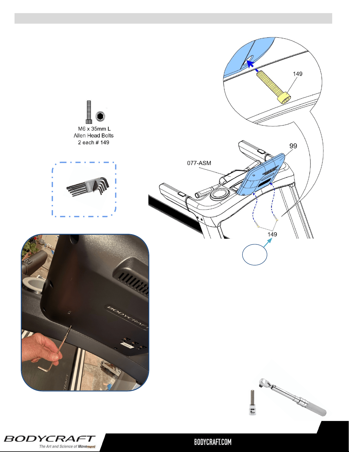
STEP 16 – Secure the Console to the Dashboard Assembly.
a. Attach the Console (099) to the Dashboard Assembly
(077-ASM) using the following hardware:
i. Two Allen Head Bolts, M6 x 35mm L (149)
13 ft-lbs
+/- 1 lbs
Fig. 14
b. Confirm the Console is completed seated
down onto the Dashboard Assembly with all
plastics flush against each other.
NOTE: This might take a bit of wiggling and
double checking for any crushed cable in the way.
ALLEN WRENCH
5mm
Recommended Tool:
Loading ...
Loading ...
Loading ...