Loading ...
Loading ...
Loading ...

6
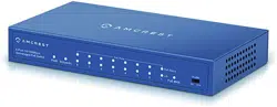
2.2.2 Back Panel
The back panel is shown in Figure 2-4.
2.2.3 PoE Power Output
10/100M RJ45 PoE Ports support IEEE802.3af and IEEE802.3at power standards.
Supports simultaneous power to 3 ports using IEEE802.3t and 8 ports using IEEE802.3af.
Total power draw cannot be over 96W.
SN Name Note
1 PWR Indicates the switch is powered on.
2 9(Uplink) Port Status LED. Blinking – data transmitting. Solid – link established. Off – no connection.
3 1, 2, 3, 4, 5, 6, 7, 8 Port Status LEDs. Blinking – data transmitting. Solid – link established. Off – no connection.
4 PoE Status This row of LEDs indicates if PoE is being used.
5 PoE MAX Indicates if the maximum PoE power available is used.
6 VLAN When enabled, communication is isolated between downlinks and uplink.
Downlinks do not communicate with each other.
Sheet 2-4
1 2 3 4 65
Figure 2.4
Loading ...
Loading ...