Loading ...
Loading ...
Loading ...
INSTALLATION
When check valve is used, drill a relief hole 3/16”
in diameter in the discharge pipe. This hole
should be located below the oor line between
the pump discharge and the check valve. Unless
such a relief hole is provided, the pump could
“air-lock” and will not pump water even though it
will run.
A gate valve should follow the check valve to
allow periodic cleaning of the check valve or re-
moval of the pump.
The remainder of the discharge line should be
as short as possible with a minimum of turns to
minimize friction head loss. Do not restrict the
discharge to sizes below 2’.
Sewage and euent applications will require a
separate sump vent. A connection is provided on
top of the sump or cover which must be piped
to the existing building vent or extended outside
with its own standpipe.
A check valve must be used in
the discharge line to prevent
back ow of liquid into the ba-
sin. The check valve should be
a free ow valve that will easily
pass solids.
CAUTION: For best perfor-
mance of check valves when
handling solids install in a hor-
izontal position or at an angle
of not more then 45°. Do not
install check valve in a vertical
position as solids may settle
in valve and prevent opening
start-up.
For automatic operation, pump must be
plugged or wired into remote oat switch or
liquid level controller. Installation instructions in-
cluded with switches and controllers should be
referred to for installation.
Pump will run continuously if plugged directly
into an electrical outlet. Care should be taken to
prevent pump running in a dry sump.
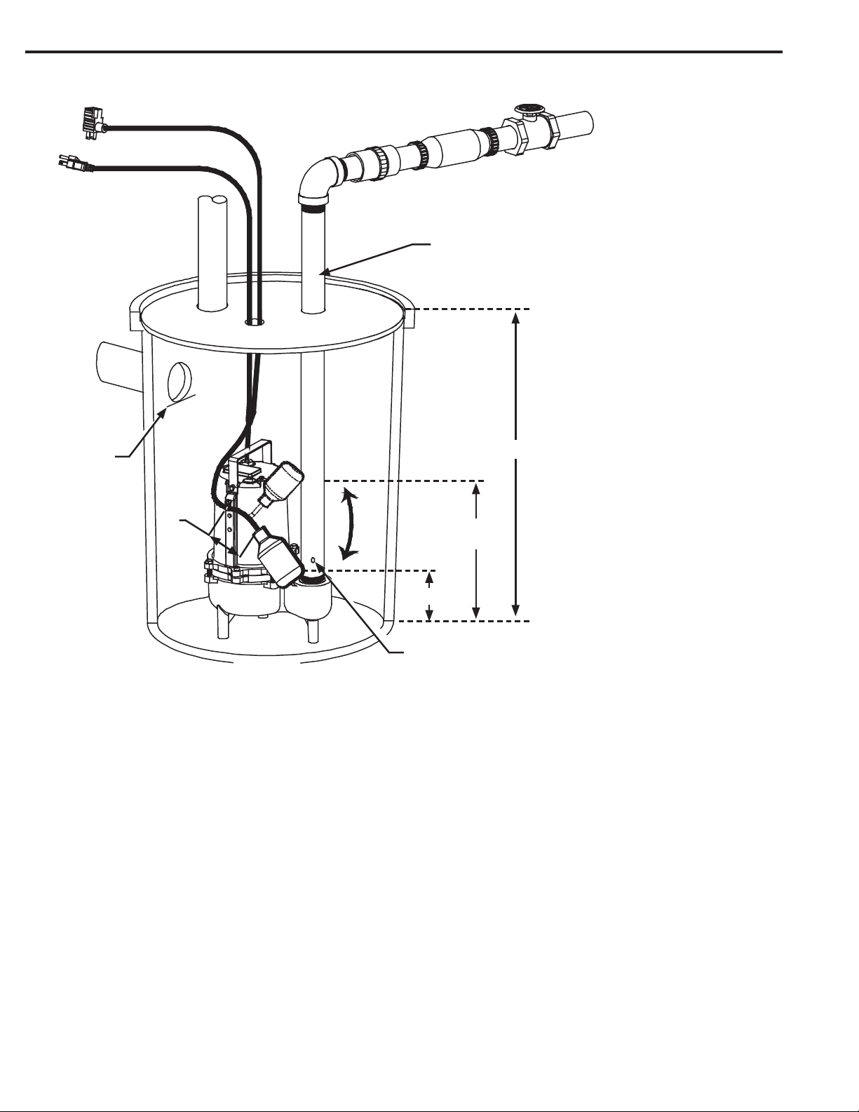
Pump must be installed in a suitable gas tight
basin which is at least 24” in diameter and
30” deep and vented in accordance with local
plumbing codes. Pump must be placed on a
hard level surface. Never place pump directly on
clay, earth or gravel surfaces.
Pump can be installed with ABS, PVC, polyeth-
ylene or galvanized steel pipe. Proper adapters
are required to connect plastic pipe to pump.
Always install a union in the discharge line, just
above the sump pit to allow for easy removal of
the pump for cleaning or repair.
Min.30”
Approximate
15.5”
Approx. 7.5”
Switch OFF
Switch ON
3/16” O.D.
Air Bleed Hole
Discharge
Pipe
Gate Valve
Check Valve
Union
Piggyback Cord
Power Cord
Vent
Inlet
Pipe
Bottom of
Inlet Pipe
3.5”
Elbow
4
Loading ...
Loading ...