Operating and Installation Instructions
Induction Cooktops
To prevent accidents and machine damage, read these instructions be‐
fo
re installation or use.
en-US M.-Nr. 09 888 630

Contents
2
IMPORTANT SAFETY INSTRUCTIONS................................................................. 4
Overview ...............................................................................................................
15
KM 6360 / KM 6365............................................................................................... 15
KM 6370 / KM 6375............................................................................................... 16
KM 6377................................................................................................................. 17
DirectSelection Plus controls................................................................................. 18
Cooking zone data................................................................................................. 19
Before using for the first time.............................................................................
22
Cleaning the cooktop for the first time .................................................................. 22
Turning on the cooktop for the first time................................................................ 22
Induction...............................................................................................................
23
How it works .......................................................................................................... 23
Noises .................................................................................................................... 24
Cookware............................................................................................................... 25
Energy saving tips ...............................................................................................
26
Power setting ranges...........................................................................................
27
Operation ..............................................................................................................
28
Basic operation...................................................................................................... 28
Turning on .............................................................................................................. 29
Selecting/changing the power level....................................................................... 29
Turning off .............................................................................................................. 29
Residual heat indicator .......................................................................................... 29
Setting the power level - expanded setting range................................................. 30
PowerFlex cooking zone........................................................................................ 30
Auto Heat-up.......................................................................................................... 31
TwinBooster / Booster ........................................................................................... 32
Keep warm function............................................................................................... 34
Timer ..................................................................................................................... 35
Timer ...................................................................................................................... 35
Turning a cooking zone off automatically .............................................................. 37
Using both timer functions at the same time......................................................... 38
Additional functions.............................................................................................
39
Stop & Go function ................................................................................................ 39
Safety features ..................................................................................................... 40
System lock / Safety lock ...................................................................................... 40
Safety shut-off ....................................................................................................... 41

Contents
3
Overheat protection ............................................................................................... 42
Cleaning and care................................................................................................
43
Programming........................................................................................................
45
Frequently asked questions................................................................................ 48
Con@ctivity ..........................................................................................................
52
IMPORTANT SAFETY INSTRUCTIONS - INSTALLATION..................................
53
Safety clearances.................................................................................................
54
Ventilation .............................................................................................................
58
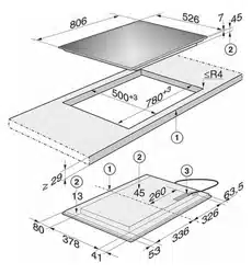
Framed cooktops.................................................................................................
59
Instructions for installation..................................................................................... 59
Installation dimensions .......................................................................................... 60
KM 6360 ........................................................................................................... 60
KM 6370 ........................................................................................................... 61
KM 6377 ........................................................................................................... 62
Installation.............................................................................................................. 63
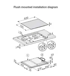
Flush-mounted (frameless) cooktops ................................................................
64
Instructions for installation..................................................................................... 64
Installation dimensions .......................................................................................... 65
KM 6365 ........................................................................................................... 65
KM 6375 ........................................................................................................... 66
Installation.............................................................................................................. 67
Electrical connection...........................................................................................
69
Caring for the environment.................................................................................
71
Technical service, data plate, warranty .............................................................
72
MieleCare..............................................................................................................
73

IMPORTANT SAFETY INSTRUCTIONS
4
When using the cooktop, follow basic safety precautions, including the fol‐
lowing:
Read all instructions before installation and use of the appliance to prevent
accidents and machine damage.
This cooktop conforms to current safety requirements. Improper
use
can, however, lead to personal injury and damage to property.
To avoid the risk of accidents and damage to the appliance,
please read these instructions carefully before using the appliance
for the first time. They contain important notes on installation,
safety, use and maintenance.
Miele cannot be held liable for damage occurring as a result of
non-compliance with these instructions.
Keep these instructions in a safe place and pass them on to any
future owners.

IMPORTANT SAFETY INSTRUCTIONS
5
Use
This coo
ktop is intended for domestic use and use in other similar
environments.
This co
oktop is not intended for outdoor use.
The cooktop is intended for domestic use only to prepare food
and keep it warm. Any other use may be dangerous.
P
ersons who lack physical, sensory or mental abilities, or experi‐
ence with the appliance should not use it without supervision or in‐
struction by a responsible person.

IMPORTANT SAFETY INSTRUCTIONS
6
Children
As w
ith any other appliance, children must be supervised.
Do not lea
ve children unattended: Children should not be alone or
unsupervised in the area where the oven is installed. Do not allow
them to sit or stand on the appliance.
Chil
dren under eight years of age must be kept away from the
cooktop unless they are constantly supervised.
Chil
dren ages eight and up may only use the cooktop without su‐
pervision if they have been shown how to use it in a safe manner,
and if they are able to recognize and understand the potential risks
of improper use.
Chil
dren must not be allowed to clean the cooktop without super‐
vision.
Be sur
e to supervise any children in the vicinity of the cooktop,
and do not let them play with it.
The co
oktop gets hot when in use and remains hot for some time
after being turned off. Keep children away from the appliance until it
has cooled down and is no longer a burn hazard.
Burn hazar
d!
Keep the spaces above and behind the cooktop clear of any items
that could draw the attention of children. Otherwise, they can be
tempted into climbing onto the appliance.
Danger of burning or scalding!
T
urn all handles away from the front of the cooktop so that children
cannot pull pots and pans down and burn themselves.
Dange
r of suffocation! Ensure that any plastic wrappings, bags,
etc. are disposed of safely and kept out of the reach of children.
Activat
e the system lock to ensure that children cannot turn on
the appliance inadvertently. Use the safety lock when the hob is in
use to prevent children from altering the settings selected.

IMPORTANT SAFETY INSTRUCTIONS
7
Technical safety
Installatio
n, repair and maintenance work should be performed by
a Miele authorized service technician in accordance with national
and local safety regulations and the provided installation instruc‐
tions. Contact Miele’s Technical Service Department for examina‐
tion, repair or adjustment. Repairs and other work by unauthorized
persons could be dangerous and may void the warranty.
Maint
enance by the user: Never repair or replace any part of the
appliance unless the instructions specifically recommend doing so.
Service work may only be performed by a qualified technician.
A d
amaged cooktop can be dangerous. Always check for visible
signs of damage. Never use a damaged appliance.
Reliable
and safe operation of the cooktop can only be guaran‐
teed if it is connected to the public power supply.
Be cer
tain your appliance is properly installed and grounded by a
qualified technician. To guarantee the electrical safety of this appli‐
ance, continuity must exist between the appliance and an effective
grounding system. It is imperative that this basic safety requirement
be met. If there is any doubt, have the electrical system of the house
checked by a qualified electrician.
P
roper installation: Make sure that your appliance has been instal‐
led correctly and that it has been grounded by a qualified technician.
T
o avoid damaging the cooktop, make sure that the connection
data (voltage and frequency) on the data plate correspond to the
building's power supply before connecting the appliance.
When in doubt, consult a qualified electrician.
Do not con
nect the appliance to the electrical supply with a pow‐
er bar or extension cord. These are a fire hazard and do not guaran‐
tee the required safety of the appliance.
F
or safety reasons, the cooktop may only be used when it has
been fully installed.

IMPORTANT SAFETY INSTRUCTIONS
8
This applianc
e must not be used in a non-stationary location (e.g.
on a ship).
Any contact with live connections or tampering with the electrical
or mecha
nical components of the cooktop will endanger your safety
and may lead to appliance malfunctions.
Do not open the casing of the cooktop under any circumstances.
Any r
epairs not performed by a Miele authorized service techni‐
cian will void the warranty.
Defective co
mponents should be replaced by Miele original parts
only. Only with these parts can the manufacturer guarantee the safe‐
ty of the appliance.
The applianc
e is not intended for use with an external timer switch
or a remote control system.
Conn
ection of the cooktop to the electrical power supply must
only be performed by a qualified electrician (see "Electrical connec‐
tion").
If
the power cord is damaged, it must be replaced by a qualified
electrician with a special power cord, which is available from Miele
Service. See "Electrical connection."
The applianc
e must be completely disconnected from the elec‐
tricity supply during installation, maintenance and repair work. En‐
sure that power is not supplied to the appliance until after it has
been installed or until any maintenance or repair work has been car‐
ried out.
Disconnect by
– removing the fuse,
– "tripping" the circuit breaker, or
– unplugging the unit (if equipped with plug). Pull the plug not the
co
rd.

IMPORTANT SAFETY INSTRUCTIONS
9
If
the cooktop is fitted with a communication module, in addition
to disconnecting the cooktop, this module must also be disconnect‐
ed from the electrical supply during installation and maintenance of
the cooktop as well as while any repair work is being carried out.
Risk of electric shock!
If t
he ceramic surface of the cooktop is defective or chipped,
cracked or broken in any way, immediately turn the cooktop off and
do not continue to use it. Disconnect the cooktop from the power
supply and contact Miele.
If
the cooktop is installed behind a cabinet door, do not close the
door while the cooktop is in operation. Heat and moisture can build
up behind the closed door and cause damage to the cooktop, cab‐
inetry, and flooring. Do not close the door until the cooktop has
completely cooled down.

IMPORTANT SAFETY INSTRUCTIONS
10
Proper use
The co
oktop gets hot when in use and remains hot for a while af‐
ter being turned off. There is a potential hazard until the residual heat
indicator goes out.
When in use, the coo
ktop emits a significant amount of heat,
which can cause objects in the vicinity to catch fire.
Never use the cooktop to heat the room.
Do not lea
ve the cooktop unattended when cooking on high pow‐
er. Spilled food will begin to smoke and cause grease splatter, which
can ignite on the cooktop.
Oil and fat
can catch fire if overheated. Never leave the appliance
unattended when cooking with oil and fat. If the oil or fat catches
fire, do not attempt to put the flames out with water.
Turn off the cooktop and smother the flames using a lid or a suitable
fire blanket.
Smother the fire or flames, or use a dry chemical extinguishing
agent or foam fire extinguisher.
S
torage in or on the appliance: Flammable materials should not
be stored in an oven or in the vicinity of the cooktop.
The flames could set the grease filters of a ventilation hood on
fire. Do not flambé under a ventilation hood.
Spr
ay canisters, aerosols and other inflammable substances can
ignite when heated. Therefore do not store such items or substances
in a drawer under the appliance. Cutlery inserts must be heat-resist‐
ant.
Never heat empty cook
ware.
Do not heat or can food in closed containers, such as tins or
sealed jars, on the cooktop, as pressure will build up in the container
and cause it to explode.

IMPORTANT SAFETY INSTRUCTIONS
11
If
the cooktop is covered, there is a risk that the material of the
cover will ignite, explode or melt if the range is still hot or if turned on
inadvertently. Never cover the cooktop with a board, cloth or protec‐
tive sheet.
If
the cooktop is turned on or accidentally turned on or if it is still
hot, metal objects on the cooktop can heat up. Other items may
melt or catch fire. Damp lids can become attached to the cooktop
by suction. Do not store items on the cooktop! Always turn the burn‐
ers off after use!
Y
ou could burn yourself on the hot cooktop. Protect your hands
with heat-resistant pot holders or gloves when handling hot pots
and pans. Do not let them get wet or damp, as this causes heat to
transfer through the material more quickly with the risk of scalding or
burning yourself.
When using
an electrical appliance, e.g. a hand mixer, near the
cooktop, make sure that the power cable does not come into con‐
tact with the hot cooktop. The cable's insulation could become
damaged.
Gr
ains of salt, sugar and sand (e.g. from cleaning vegetables) can
cause scratches if they get under pan bases. Make sure that the ce‐
ramic surface is clean before placing pans on it.
E
ven a light object can cause damage to the ceramic cooktop in
certain circumstances. Do not drop anything on the ceramic surface.
Do not place ho
t pans on the sensor buttons and display as this
could cause damage to the electronics underneath. Do not place hot
pans on the area around the display.

IMPORTANT SAFETY INSTRUCTIONS
12
Do not all
ow solid or liquid sugar, or pieces of plastic or aluminum
foil to get onto the burners when they are hot, as they can damage
the ceramic surface when it cools down. If this should occur, turn off
the appliance and scrape off all the sugar, plastic or aluminum resi‐
dues while still hot, using a shielded scraper blade. Wear oven
gloves. Allow the burners to cool down and clean them with a suita‐
ble ceramic cleaning agent.
P
ans that boil dry can cause damage to the ceramic glass. Do not
leave the appliance unattended while it is being used.
P
ots and pans with bases with pronounced edges or ridges can
scratch the ceramic burner. Only use pots and pans with smooth
bases.
Lift pans into position on the cooktop. Sliding them into place can
cause scuffs and scratches.
Fir
e hazard! Loose-fitting or hanging garments can catch fire. Be
sure to wear appropriately fitting clothing when cooking. Never allow
loose clothing or flammable materials to come into contact with the
burners while the burners are in use.
Because
induction heating works so quickly, the temperature of
the cookware bottom can quickly reach the ignition point of oils and
fats. Never leave the cooktop unattended when it is on!
Do not hea
t oils and fats for longer than one minute, and never
use the booster.
F
or people who have a heart pacemaker: Please note that the
area immediately surrounding the cooktop is electromagnetically
charged. It is very unlikely to affect a pacemaker. However, if in any
doubt, consult the manufacturer of the pacemaker or your doctor.
Ob
jects affected by electromagnetic fields, for instance credit
cards, CDs and calculators, should be kept away from the cooktop
when it is on.

IMPORTANT SAFETY INSTRUCTIONS
13
Metal ut
ensils stored in a drawer under the cooktop can become
hot if the appliance is used intensively for a long time. Do not store
any metal items or utensils in a drawer under the cooktop.
This co
oktop is equipped with a cooling fan. If a drawer is fitted
directly underneath the cooktop, ensure that there is sufficient space
between the drawer and its contents and the underside of the appli‐
ance in order to ensure sufficient ventilation of the cooktop. Do not
store pointed or small items or paper in the drawer. They could get
in through the ventilation slots or be sucked into the housing by the
fan and damage the fan or impair cooling.
Do not use two pans on a cooking zone at the same time.
If
the cookware only partially covers the cooking or roasting zone,
the handle could become very hot.
Make sure to place the cookware in the middle of the cooking or
roasting zone.
Wet sponges or clothes can cause burns due to hot steam if they
are used to wipe spilled food off a hot burner. Some cleansers can
emit hazardous vapors if they are applied to a hot surface. Be care‐
ful when cleaning the cooktop.
If
the burner is damaged, cleansers or spilled food can penetrate
the glass surface and cause a short-circuit. Never cook on a dam‐
aged burner. Contact an electrician immediately.

IMPORTANT SAFETY INSTRUCTIONS
14
Cleaning and care
Do not use a st
eam cleaner to clean the cooktop.
The steam may reach electrical components and cause a short cir‐
cuit.
If
the cooktop is built in over a self cleaning oven, the cooktop
should not be used while the self cleaning process is being carried
out, as this could trigger the overheating protection mechanism on
the cooktop (see relevant section).
Overview
15
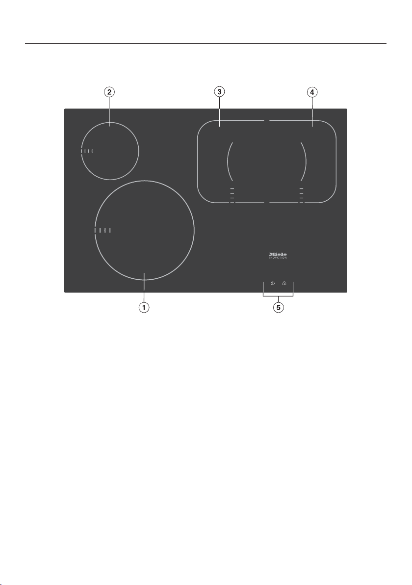
KM 6360 / KM 6365
a
Cooking zone with TwinBooster
b
Cooking zone with Booster
c
PowerFlex cooking zone with TwinBooster
d
PowerFlex cooking zone with TwinBooster
cd
can be combined to form PowerFlex cooking zone
e
DirectSelection Plus controls

Overview
16
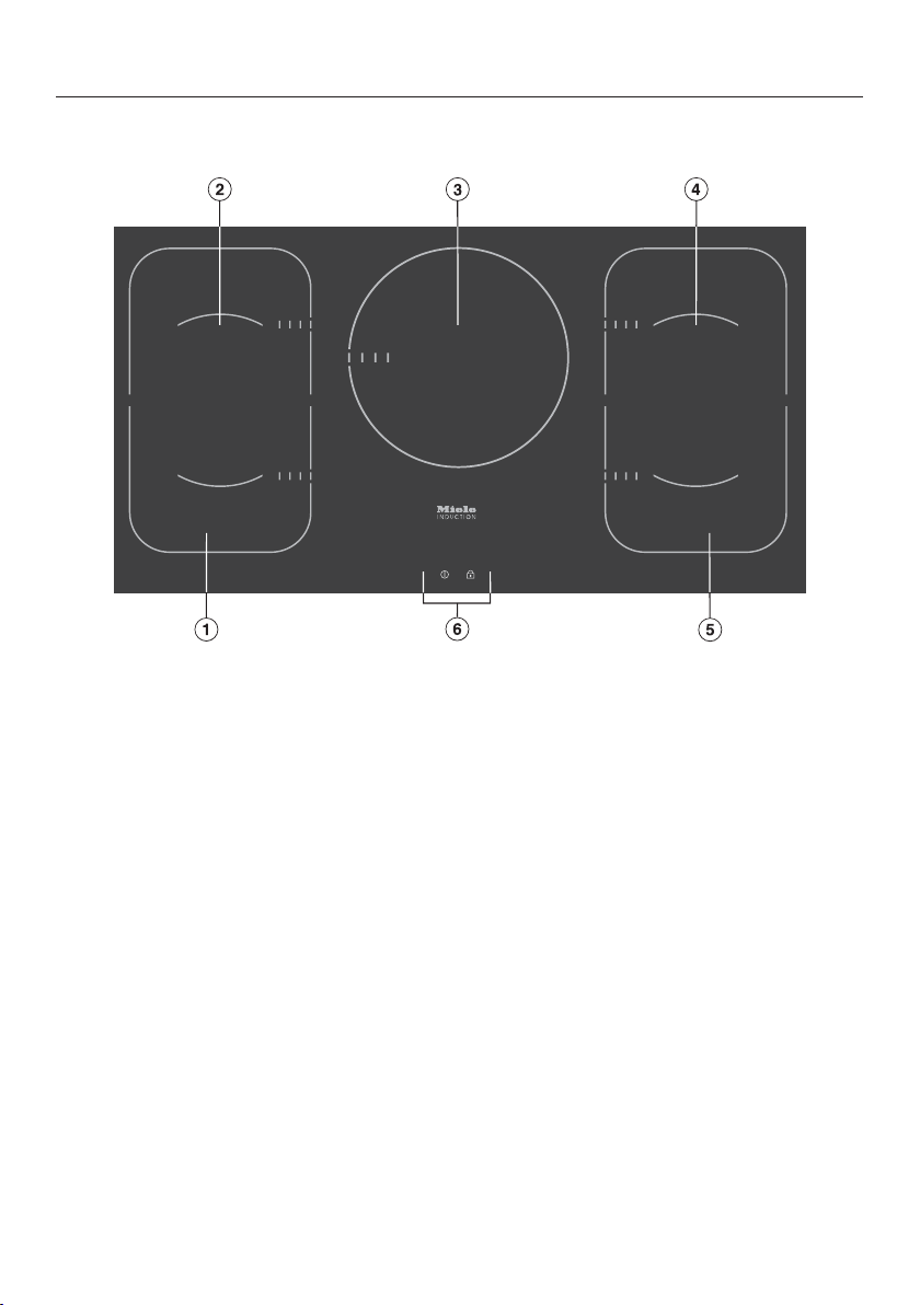
KM 6370 / KM 6375
a
Cooking zone with Booster
b
PowerFlex cooking zone with TwinBooster
c
PowerFlex cooking zone with TwinBooster
bc
can be combined to form PowerFlex cooking zone
d
Cooking zone with Booster
e
Cooking zone with TwinBooster
f
DirectSelection Plus controls
Overview
17
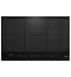
KM 6377
a
PowerFlex cooking zone with TwinBooster
b
PowerFlex cooking zone with TwinBooster
ab
can be combined to form PowerFlex cooking zone
c
Cooking zone with TwinBooster
d
PowerFlex cooking zone with TwinBooster
e
PowerFlex cooking zone with TwinBooster
de
can be combined to form PowerFlex cooking zone
f
DirectSelection Plus controls
Overview
18
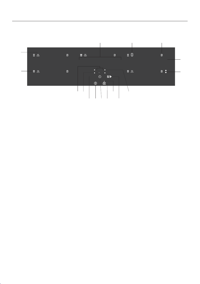
DirectSelection Plus controls
0123456789 0123456789 0123456789
0123456789 0123456789
h
f
o
88
m
e
c
l
n
p
k
i
a
b
d
g
j
h
Sensor buttons
a
Turning the cooktop On/Off
b
Activating and deactivating the System lock/Safety lock
c
Switching the timer to hours
d
Timer
- For turning on and off
- For switching between timer functions
- For selecting a cooking zone (see "Turning a cooking zone off automatically")
e
Activating/deactivating the Stop & Go function
f
For selecting the power setting
g
For switching the Booster/TwinBooster On/Off
h
Turning the PowerFlex cooking zone On/Off
i
Control scale
- For setting a timer / turn-off after duration
- For setting the power level for middle rear cooking zone (depending on mod‐
el)
j
Turning the keep warm function On/Off
Indicators
k
Residual heat
l
For half hours if the timer setting is over 99 minutes
Overview
19
m
System lock/Safety lock activated
n
For cooking zone selection, e.g., right rear cooking zone
o
TwinBooster activated
Level 1
Level 2
p
Timer display
to Time in minutes
. t
o . Time in hours
System lock/Safety lock activated
Demo mode activated
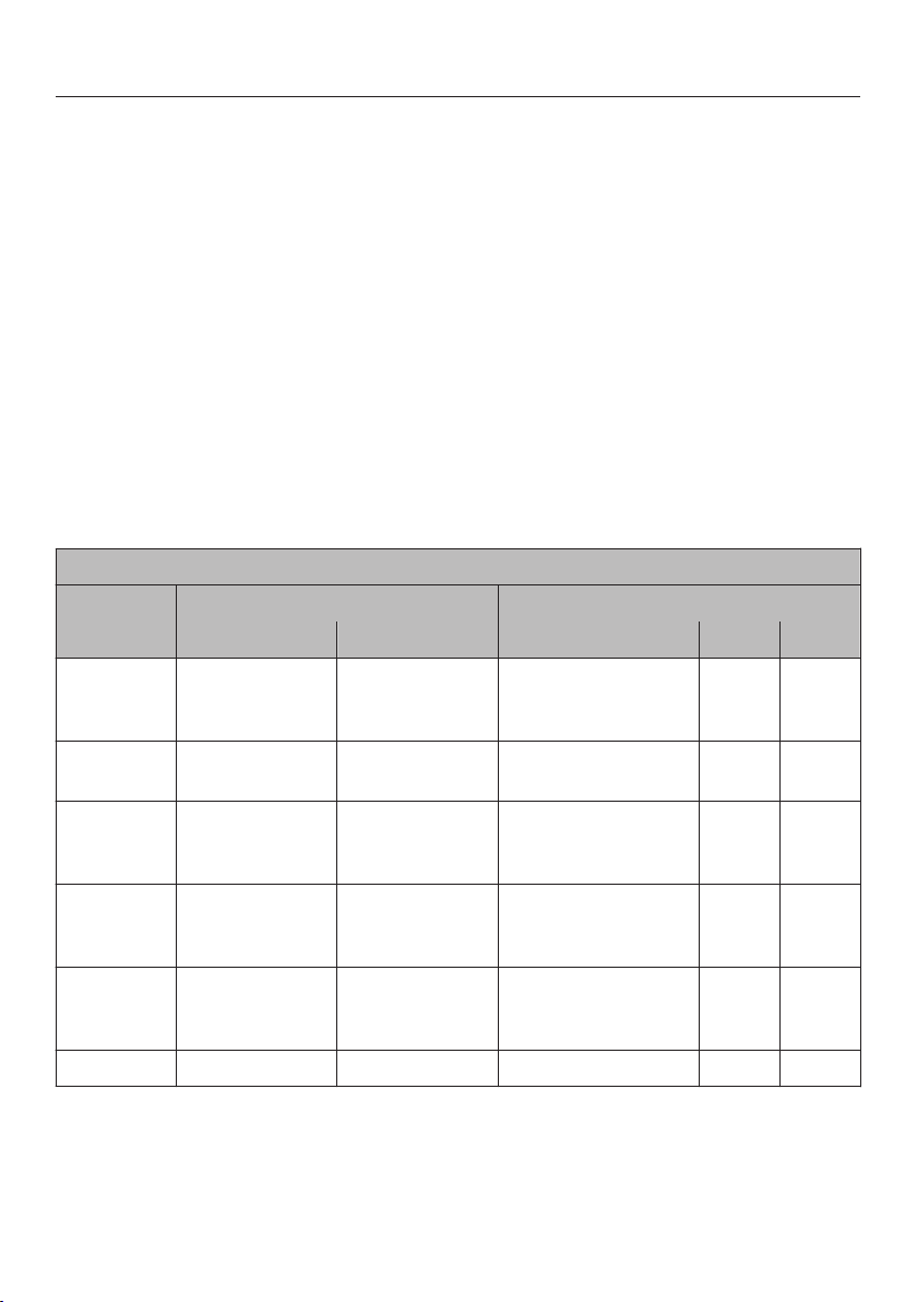
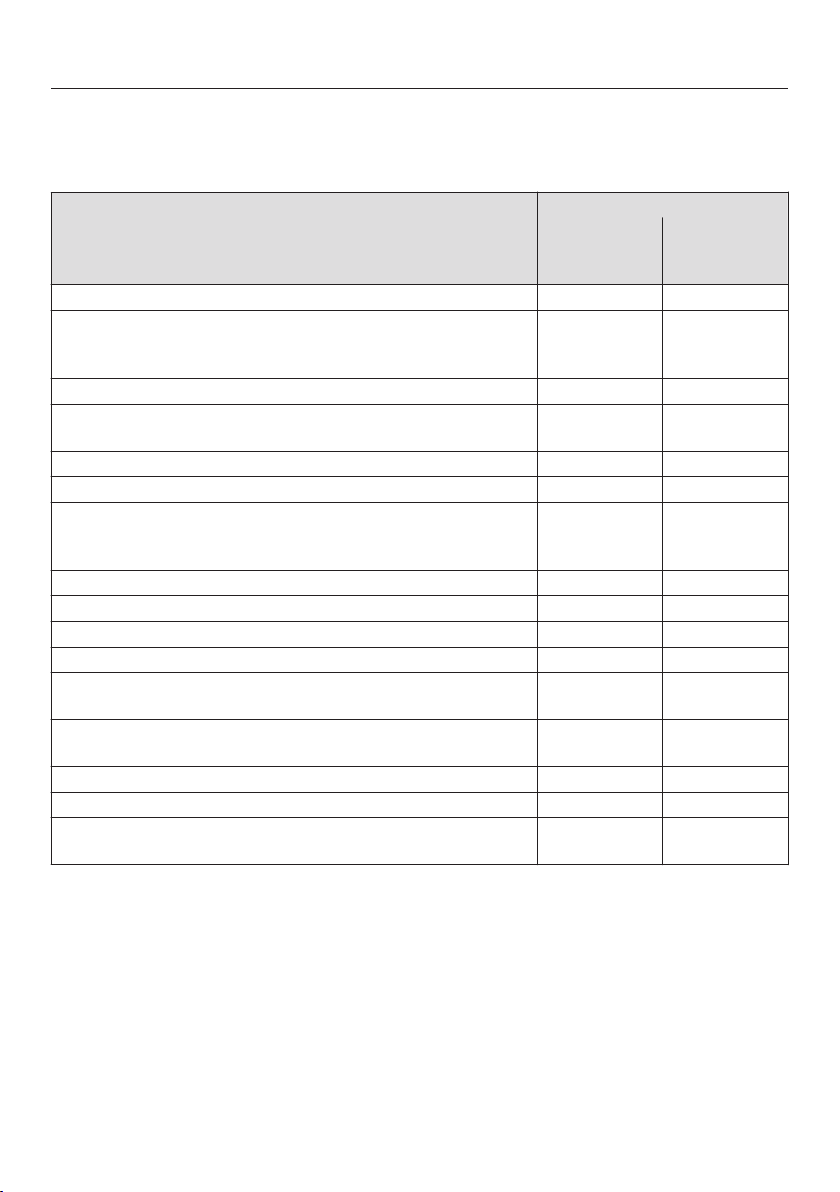
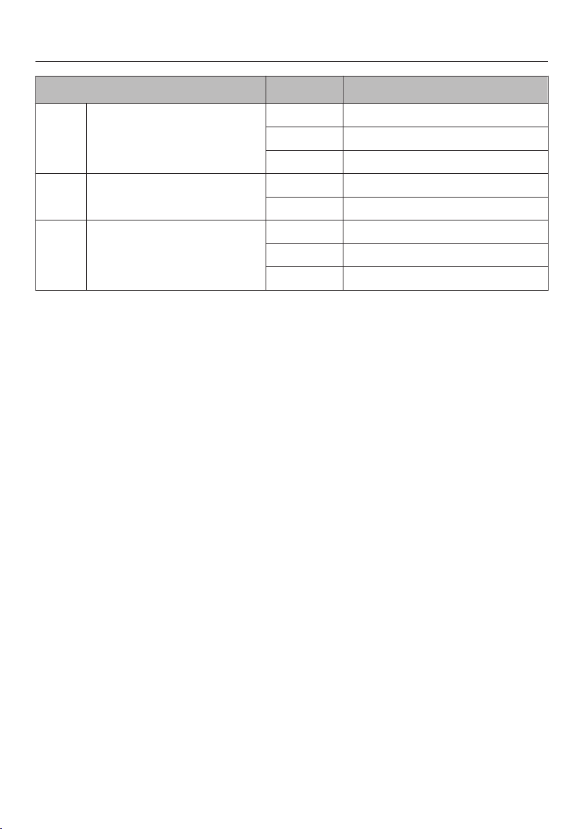
Cooking zone data
KM 6360 / KM 6365
Cooking
zone
Diameter* Ø
Output in watt**
Inches Centimeters 208 V 240 V
7–11 18–28 Normal
T
winBooster, Level 1
TwinBooster, Level 2
2200
2700
3350
2500
3100
3850
4–6 10–16 Normal
Boost
er
1250
1700
1450
1900
6–9 15–23 Normal
TwinBooster, Level 1
TwinBooster, Level 2
1900
2700
3350
2200
3100
3850
6–9 15–23 Normal
T
winBooster, Level 1
TwinBooster, Level 2
1900
2700
3350
2200
3100
3850
+ 8¹/₂–9 /
6x9–9x15
22–23 /
15 x 23 – 23 x
39
Normal
T
winBooster, Level 1
TwinBooster, Level 2
3050
4300
6700
3550
5000
7700
Total 6700 7700
* Cookware of any diameter may be used within the specified range.
** The wattage quoted may vary depending on the size and material of the pans used.
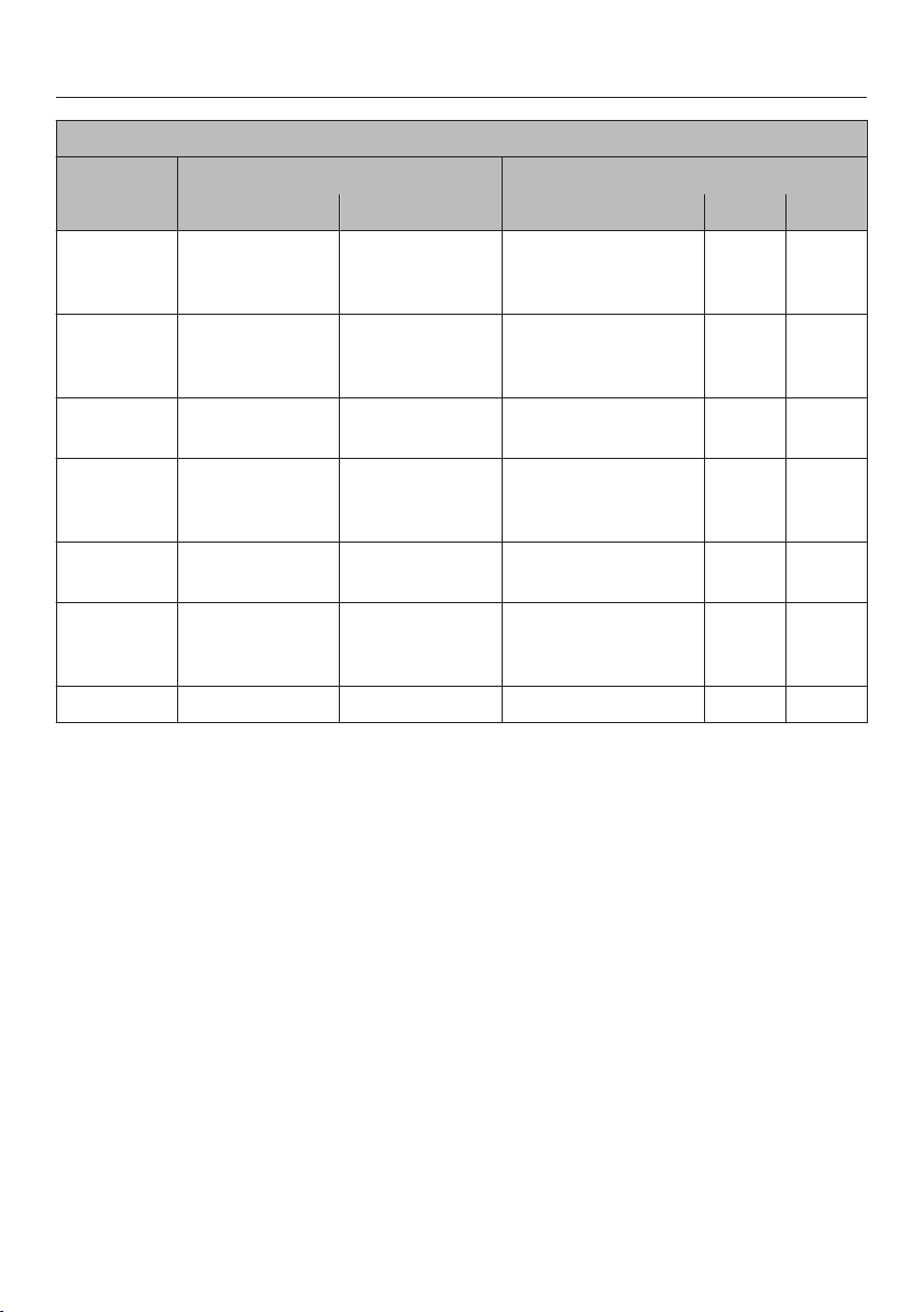
Overview
20
KM 6370 / KM 6375
Cooking
zone
Diameter* Ø
Output in watt**
Inches Centimeters 208 V 240 V
6–9 15–23 Normal
T
winBooster, Level 1
TwinBooster, Level 2
1900
2700
3350
2200
3100
3850
6–9 15–23 Normal
T
winBooster, Level 1
TwinBooster, Level 2
1900
2700
3350
2200
3100
3850
5¹/₂–8 14–20 Normal
Boost
er
1700
2250
1950
2600
7–11 18–28 Normal
T
winBooster, Level 1
TwinBooster, Level 2
2200
2700
3350
2500
3100
3850
4–6 10–16 Normal
Boost
er
1250
1700
1450
1900
+ 8¹/₂–9 /
6x9–9x15
22–23 /
15 x 23 – 23 x
39
Normal
T
winBooster, Level 1
TwinBooster, Level 2
3050
4300
6700
3550
5000
7700
Total 10000 11500
* Cookware of any diameter may be used within the specified range.
** The wattage quoted may vary depending on the size and material of the pans used.
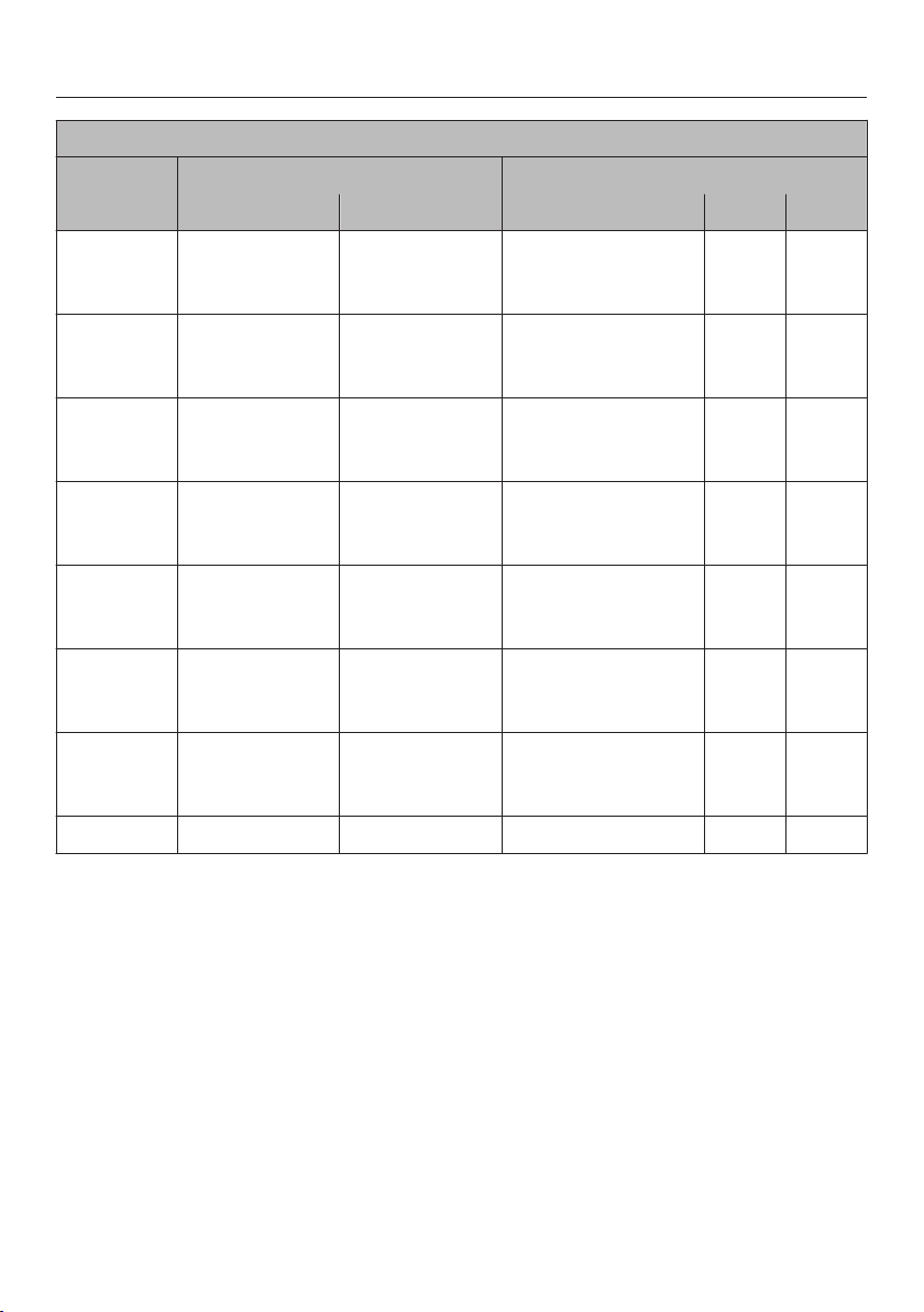
Overview
21
KM 6377
Cooking
zone
Diameter* Ø
Output in watt**
Inches Centimeters 208 V 240 V
6–9 15–23 Normal
T
winBooster, Level 1
TwinBooster, Level 2
1900
2700
3350
2200
3100
3850
6–9 15–23 Normal
T
winBooster, Level 1
TwinBooster, Level 2
1900
2700
3350
2200
3100
3850
7–11 18–28 Normal
T
winBooster, Level 1
TwinBooster, Level 2
2200
2700
3350
2500
3100
3850
6–9 15–23 Normal
T
winBooster, Level 1
TwinBooster, Level 2
1900
2700
3350
2200
3100
3850
6–9 15–23 Normal
T
winBooster, Level 1
TwinBooster, Level 2
1900
2700
3350
2200
3100
3850
+ 8¹/₂–9 /
6x9–9x15
22–23 /
15 x 23 – 23 x
39
Normal
Boost
er
3050
3350
3550
3850
+ 8¹/₂–9 /
6x9–9x15
22–23 /
15 x 23 – 23 x
39
Normal
T
winBooster, Level 1
TwinBooster, Level 2
3050
4300
6700
3550
5000
7700
Total 10000 11500
* Cookware of any diameter may be used within the specified range.
** The wattage quoted may vary depending on the size and material of the pans used.

Before using for the first time
22
Please adhere the extra data plate for
the appliance supplied with this doc‐
umentation in the space provided in
the "After sales service, data plate,
warranty" section of this manual.
Remo
ve any protective foil and stick‐
ers.
Cleaning the cooktop for the
first time
Befo
re first use, wipe down the appli‐
ance with a damp cloth and dry it.
Turning on the cooktop for the
first time
Metal components are protected by a
conditioning agent. Smells and vapor
may occur when the appliance is used
for the first time. The heating of the in‐
duction coils also causes odors in the
first few
hours of operation. With each
subsequent use, the odor is reduced
until it disappears entirely.
The smell and any vapors do not indi‐
cat
e a faulty connection or a defective
appliance and are not harmful to your
health.
Please note that the heat-up time for
inductio
n cooktops is very much
shorter than for conventional cook‐
tops.

Induction
23
How it works
An induction coil is located under each
cooking zone. When a zone is turned
on, this coil cr
eates a magnetic field
that impacts directly on the base of the
pan and heats it up. The cooking zone
itself is heated up indirectly by the heat
given off by the pan.
An induction cooking zone only works
when a ferr
omagnetic pan is placed on
it (see "Cookware"). The induction
cooking zone automatically recognizes
the size of the pan.
On the control scale of the cooking
zone, power levels 1 t
o 9 flash if:
– No cookware or unsuitable cookware
(it
ems without a magnetizable bot‐
tom) is being used.
– The bottom diameter of the cook‐
ware being used is too small.
– The cookware is removed from a
cooking zone that is on.
If suitable cookware is placed on the
coo
king zone within 3 minutes, you can
continue as usual.
If no cookware or if unsuitable cook‐
war
e is used, the cooking zone will au‐
tomatically turn off after 3 minutes.
When the appliance is turned on
e
ither inadvertently or by mistake, or
when there is residual heat present,
there is the risk of the metal items
heating up.
Burn hazard!
Do not use the cooktop as a storage
space. T
urn the cooking zones off af‐
ter use with the appropriate sensor
buttons.

Induction
24
Noises
When you use an induction cooking
zone, the foll
owing noises may occur,
depending on the type and shape of
the cookware bottom:
On the higher power settings, it might
buzz. This will decr
ease or cease alto‐
gether when the power setting is re‐
duced.
Cookware with bottoms made of differ‐
ent mat
erials (e.g. sandwich bottoms)
may produce a crackling noise.
Whistling may occur if connected cook‐
ing
zones (see "Booster") are simulta‐
neously in use and cookware with bot‐
toms made of different materials are on
them.
The electronics may produce a clicking
sound, especially at lower power set‐
tings.
You might hear a whirring sound when
the coo
ling fan turns on. It turns on to
protect the electronics when the cook‐
top is being used intensively. The fan
may continue to run after the appliance
has been turned off.

Induction
25
Cookware
Suitable cookwar
e is made of:
– Stainless steel with a magnetizable
bott
om
– Enamel-coated steel
– Cast iron
Unsuitable cookwar
e is made of:
– Stainless steel with a non-magnetiza‐
ble bott
om
– Aluminum or copper
– Glass, ceramics, earthenware, stone‐
war
e
To test whether a pot or pan is suitable
for use on an
induction cooktop, hold a
magnet to the base of the pan. If the
magnet sticks, the pan is suitable.
If an unsuitable pan is used, the 1-9
power levels will flash on the control
scale of the cooking zone.
The composition of the pan bottom can
affect the evenne
ss of the cooking re‐
sults (e.g., when making pancakes).
– To make optimum use of the cooking
zon
es, choose pans with diameters
larger than the innermost markings
but smaller than the outermost mark‐
ings (see "Cooking zone data"). If the
diameter of the pan is smaller than
the innermost marking, the pan will
not be recognized and the 1-9 power
levels will flash on the control scale
of the zone.
– Pots and pans with bases with pro‐
no
unced edges or ridges can scratch
the ceramic cooking zone. Only use
pots and pans with smooth bases.
– Lift pans into position on the cook‐
t
op. Sliding them into place can
cause scuffs and scratches.
– Often the maximum diameter quoted
by manufactur
ers refers to the diam‐
eter of the top rim of the pot or pan.
The diameter of the base (generally
smaller) is more important.

Energy saving tips
26
– Use a lid whenever possible to mini‐
miz
e heat loss.
– For small quantities, select a small
pan. A small pan on a small burner
uses less en
ergy than a large, only
partially filled pan on a large burner.
– Cook with as little water as possible.
– Once food has come to the boil or
the pan is hot for fr
ying, reduce the
heat to a lower power setting.
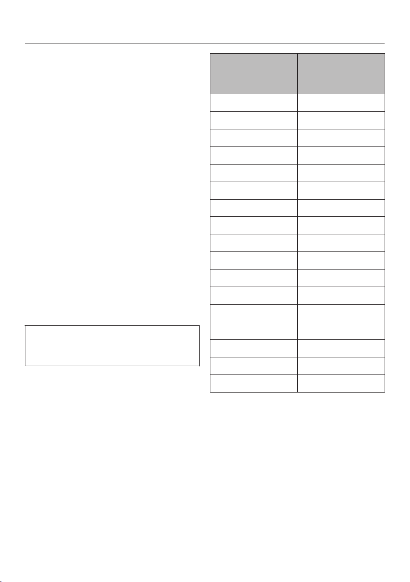
Power setting ranges
27
The cooktop is programmed with 9 power levels at the factory. If you wish to fine-
tune a setting
, you can extend the power setting range to 17 power levels (see
"Programming").
Setting ranges
Default
(9 power
levels)
Extended
(17 power
levels)
Keep warm level h h
Melting butter
Dissolving gelatin
Meltin
g chocolate
1–2 1–2.
Making pudding 2 2–2.
Warming small quantities of liquid
Cooking rice
3 3–3.
Thawing frozen vegetables (blocks) 3 2.–3
Making oatmeal 3 2.–3.
Warming liquid and half-set foods
Makin
g omelettes or lightly fried eggs
Steaming fruit
4 4–4.
Cooking dumplings 4 4–5.
Steaming vegetables or fish 5 5
Thawing and heating frozen food 5 5–5.
Gently frying eggs (without overheating the fat) 6 5.–6.
Bringing large quantities of food to a boil, e.g., casseroles.
Thi
ckening custard and sauces, e.g., hollandaise.
6–7 6.–7
Gently frying meat, fish or sausages (without overheating
the fat)
6–7 6.–7.
Frying pancakes, etc. 7 6.–7
Braising for stews 8 8–8.
Boiling large quantities of water
Bring
ing to a boil
9 9
These settings should only be taken as a guide. The power of the induction coils will vary
depending on the size and material of the pan. For this reason, it is possible that the set‐
tings will need to be adjusted slightly to suit your pans. As you use the cooktop, you will get
to know which settings suit your pans best. For new cookware whose properties for use
you are not yet familiar with, set the next lowest power level than the one specified.

Operation
28
Basic operation
The glass ceramic cooking zone is
equipped
with electronic sensor but‐
tons that react to finger contact. During
activation, the On/Off sensor button
must be pressed somewhat longer than
the other buttons for safety reasons.
Each reaction of the buttons is ac‐
knowledged with an acoustic signal.
When the cooktop is turned off, only
the pr
essed symbols for the On/Off
and System Lock/Safety Lock sen‐
sor buttons are visible. When you
switch on the cooktop, all other sensor
buttons light up. When you turn on the
cooking zone, the sensor button
lights up in brightness level 2, and the
through sensor buttons light up in
brightness level 1.
When you set a power level, the sen‐
sor buttons light up to the set power
stage in brightness level 2.
If the booster or keep warm function is
set, the corresponding sensor button
lights up in brightness level 2.
Malfunction due to dirty and/or cov‐
ered sensor buttons
The sensor buttons do not react or
unintentional switching procedures
result, perhaps even the automatic
deactivation of the cook top (see
"Safety switch-off"). Hot cookware
on the sensor buttons/indicator
lights can damage the connected
electronic module.
Keep the sensor buttons and indica‐
t
or lights clean, do not place any ob‐
jects on them, and do not put hot
cookware on them.

Operation
29
Fir
e hazard!
Do not leave the cooktop unattended
during
operation!
Please note that the heat-up time for
induction cooktops is shorter than
for conventional cooktops.
Turning on
T
o turn on the cooktop, briefly touch
the sensor button.
All of the sensor buttons will light up. If
no fur
ther entry is made, the cooktop
will turn itself off after a few seconds for
safety reasons.
T
o turn on a cooking zone, tap the
sensor button on the corresponding
control scale.
Selecting/changing the power
level
T
ap the sensor button for the desired
power level on the corresponding
control scale.
Turning off
T
o turn off a cooking zone, tap the
sensor button on the corresponding
control scale.
T
o turn off the cooktop and thus all
cooking zones, tap the sensor
button.
Residual heat indicator
When a cooking zone is hot, the residu‐
al heat in
dicator and the sensor but‐
ton light up on the control scale after
deactivation.
The lines of the residual heat indicator
go ou
t one after another as the cooking
zones cool down. The last bar and the
sensor button go out together.
The residual heat indicators will flash if
ther
e is a power cut during use or
while residual heat is still present or if
you have opened the programming
function while residual heat is still
present.
Risk of b
urns! Do not touch the
burners while the residual heat indi‐
cators are on.

Operation
30
Setting the power level - ex‐
panded setting
range
T
ap the control scale between the
sensor buttons.
The sensor buttons in front of and be‐
hind the medium leve
l light up brighter
than the other buttons.
Example:
If you have select
ed power setting 7.,
the numbers 7 and 8 will be brighter
than the other numbers.
PowerFlex cooking zone
You can combine the PowerFlex cook‐
ing
zones into one large PowerFlex
cooking zone (see the "Overview –
Cooking zone" chapter). The settings
for the cooking zone are controlled us‐
ing the front or left PowerFlex burner.
Activating
On the con
trol scale, use the sym‐
bol to tap the sensor button.
T
ap the sensor button.
Set the power level on
the control
scale of the front or left cooking
zone.
Deactivating
T
ap the sensor button.
Operation
31
Auto Heat-up
When Auto Heat-up has been activat‐
ed, t
he cooking zone turns on automat‐
ically at the highest level and then
switches to the previously selected
continued cooking level. The heat-up
time depends on which continued
cooking level has been chosen (see
chart).
Activating
T
ap the sensor button of the required
continued cooking level until an audi‐
ble tone sounds and the sensor but‐
ton starts to flash.
During the heat-up time, the set contin‐
ued cooking level flashes.
W
ith extended power levels (see "Pro‐
gramming"), the power levels before
and after the intermediate power level
will flash when an intermediate power
level is selected.
When you change the continued
coo
king level, you deactivate Auto
Heat-up.
Deactivating
T
ap the sensor button of the set con‐
tinued cooking level.
or
sele
ct a different power level.
Continued
cooking level*
Auto Heat-up
time
[min : sec]
1 approx. 0 : 15
1. approx. 0 : 15
2 approx. 0 : 15
2. approx. 0 : 15
3 approx. 0 : 25
3. approx. 0 : 25
4 approx. 0 : 50
4. approx. 0 : 50
5 approx. 2 : 00
5. approx. 5 : 50
6 approx. 5 : 50
6. approx. 2 : 50
7 approx. 2 : 50
7. approx. 2 : 50
8 approx. 2 : 50
8. approx. 2 : 50
9 –
*The continued cooking levels with a dot are
only available if the number of power levels
has been e
xtended (see "Programming").

Operation
32
TwinBooster / Booster
The cooking zones are equipped with a
boost
er or TwinBooster (see "Overview
– Cooking zone"). You can use the
booster for a maximum of two cooking
zones at the same time.
When activated, the power is boosted
for a maximum o
f 15 minutes so that
large quantities can be heated quickly,
e.g., pasta water.
If the booster function is turned on
when
– no power level has been selected,
the co
oking zone will revert automati‐
cally to level 9 at the end of the
booster time or if the booster func‐
tion is turned off before this.
– a power level has been selected, the
coo
king zone will revert automatically
to the setting selected at the end of
the booster time or if the booster
function is turned off before this.
Two cooking zones are connected so
the power for the boost
er can be ach‐
ieved. The connected zone will operate
at reduced power while the booster is
on. This has one of the following ef‐
fects:
– If the Auto Heat-up was previously
active, it will be turned off.
– The power level that is set will be re‐
duced.
– The connected cooking zone will be
turned off.

Operation
33
During the booster time, the
sensor
button and all of the sensor buttons
on the control scale are at brightness
level 2.
Activating the booster
T
ap the sensor button on the con‐
trol scale for the desired cooking
zone.
Selec
t a power level if required.
T
ap the sensor button.
TwinBooster level 1 activation
Tap the sensor button on the con‐
trol scale for the desired cooking
zone.
Selec
t a power level if required.
T
ap the sensor button.
The
indicator light for TwinBooster
level 1 comes on.
TwinBooster level 2 activation
T
ap the sensor button on the con‐
trol scale for the desired cooking
zone.
Selec
t a power level if required.
T
ap the sensor button twice.
The
indicator light for TwinBooster
level 2 comes on.
Turning the booster/TwinBooster
On/Off
T
ap the sensor button:
– once (booster)
– until the indicator lights go off (Twin‐
Boo
ster)
or
sele
ct a different power level.

Operation
34
Keep warm function
The keep warm function is for keeping
food warm that has just been cook
ed,
i.e., food that is still hot. It is not for
reheating cold food.
If the keep warm function has been ac‐
tivat
ed, the cooking zone will turn off
automatically after a maximum of 2
hours.
– Only use pans for keeping food
warm. Cover the pan with a lid.
– It is not necessary to stir the food
while
it is being kept warm.
– Nutrients are lost when food is
coo
ked, and continue to diminish
when food is kept warm. The longer
food is kept warm for, the greater the
loss of nutrients. Try to ensure that
food is kept warm for as short a time
as possible.
Turning the keep warm function
On/Off
T
ap the sensor button for the de‐
sired cooking zone.
Timer
35
The cooktop has to be turned on if
you wish t
o use the timer.
You can set a time between 1 minute
() and 9 hours (.).
The timer can be used for two different
functions:
– For setting the timer
– For turning off a cooking zone auto‐
matic
ally.
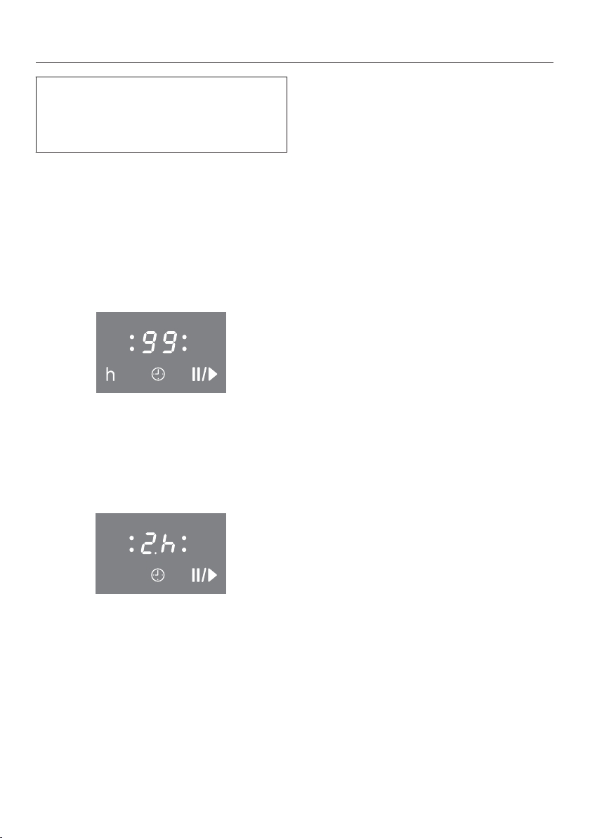
A time up to 99 minutes is set and dis‐
played in minut
es.
In case of a time of more than 99 mi‐
nut
es, the timer must be switched to
hours (h). The time is set in half-hour
steps. Half-hours are indicated by a dot
following the number, for example, 2 h
30 min:
h
Timer
Setting the minutes
Example: You want to set a time of 15
minu
tes.
T
urn the cooktop on.
T
ap the sensor button.
The senso
r button flashes. ap‐
pears in the timer display, and the right
flashes.
First the tens digit is set then the units
digit.
T
ap the sensor button on the control
scale that corresponds to the tens
position (1 in this case).
The timer display will change and will
star
t flashing on the right.
T
ap the sensor button on the control
scale that corresponds to the ones
position (5 in this case).
The timer display will change. jumps
t
o the left and appears on the right.
After several seconds, the sensor
butt
on and timer display light up con‐
stantly. The timer starts to count down.

Timer
36
Setting the hours
To set full hours, tap the respective
sen
sor button on the control scale. To
set the half hours, tap the space be‐
tween 2 sensor buttons on the control
scale.
Example: You want to set a time of 2
hou
rs and 30 minutes.
T
urn the cooktop on.
T
ap the sensor button.
The senso
r button flashes. ap‐
pears in the timer display, and the right
flashes.
T
ap the sensor button to switch the
display to hours.
T
ap the control scale between the
and sensor buttons.
After several seconds, the sensor
butt
on and timer display light up con‐
stantly. The timer starts to count down.
Changing the timer
T
ap the sensor button.
Set a new time, as described above.
Deleting the timer
T
ap the sensor button.
On the contr
ol scale, tap the sensor
button.

Timer
37
Turning a cooking zone off au‐
t
omatically
You can set a time after which the
coo
king zone will turn off automatically.
This function can be used on all zones
at the same time.
If the programmed time is longer than
the maximum time allowed, the safety
shut-off function will turn off the cook‐
ing
zone automatically when the maxi‐
mum time has elapsed (see "safety
shut-off").
Select a power level for the cooking
zone
you require.
K
eep tapping the sensor button
until the indicator light for this cook‐
ing zone starts flashing.
If several cooking zones are on, the in‐
dicat
or lights flash in a clockwise di‐
rection, starting with the left front.
Selec
t the time you require.
If you want t
o set another cooking
zone to turn off automatically, follow
the same steps as described above.
If more than one turn-off time is pro‐
gr
ammed, the shortest time remaining
will be displayed, and the respective
indicator light flashes. The other indi‐
cator lights light up constantly.
If you want t
o see the other remaining
times, keep tapping the sensor
button until the desired indicator light
flashes.

Timer
38
Using both timer functions at
the same time
The timer and automatic turn-off func‐
tions can be used at the same time.
If you have programmed in one or more
turn-o
ff times, and would like to use the
timer as well:
T
ap the sensor button until the in‐
dicator lights of the programmed
cooking zones light up constantly
and appears in the timer display.
Set a new time as described above.
If you have set the timer and would like
t
o program one or more turn-off times
as well:
K
eep tapping the sensor button
until the indicator light for the desired
cooking zone starts flashing.
Set a new time as described above.
Shortly after the last touch, the shortest
remaining time will come up in the timer
display.
If you would like to call the other re‐
maining times so that they appear in
the display:
T
ap the sensor button until:
– The indicator light for the desired
coo
king zone starts flashing (auto‐
matic turn-off).
– The timer display starts flashing.
Starting with the shortest time remain‐
ing which is shown in the display, all
coo
king zones which are turned on and
the timer are selected clockwise.

Additional functions
39
Stop & Go function
When activated, the Stop & Go reduces
the power of all coo
king zones in use to
power level 1.
The power levels of the zones and set‐
ting of the timer cannot be changed
and the cooktop can only be turned off.
A set timer and booster time continue
to run. The Auto Heat-up time and set
times for automatic turn-off are stop‐
ped.
When Stop & Go is deactivated, the
cooking zones will run on the power
level
that was previously selected and
the Auto Heat-up time and automatic
turn-off times start to run again.
If the Stop & Go function is not deacti‐
vat
ed, the cooktop turns off automati‐
cally after 1 hour.
Activation / deactivation
T
ap the sensor button.
Use this function to clean the controls
quickly or if ther
e is a danger over boil‐
ing over.

Safety features
40
System lock / Safety lock
The system lock and safety lock are
deactiva
ted if there is a power out‐
age.
Three-finger control is the default set‐
ting. Y
ou can change the default to
one-finger control (see "Program‐
ming").
Your cooktop is equipped with a safety
lock
to prevent the cooktop and the
cooking zones being turned on or any
settings being altered.
The sys
tem lock is activated when the
cooktop is turned off. When it is acti‐
vated, the cooktop cannot be turned on
and the timer cannot be used. The
cooktop is programmed so that the
system lock must be activated manual‐
ly. It can be programmed to be activat‐
ed automatically 5 minutes after the
cooktop has been turned off if the sys‐
tem lock is not manually activated first
(see "Programming").
The safety lock is activa
ted when the
cooktop is turned on. When the safety
lock is activated, the cooktop can be
operated only under certain conditions:
– The power levels for the cooking
zones and the timer settings cannot
be changed.
– The cooking zones, entire cooktop,
and the timer can be turned off, but
once turned off cannot be turned on
again.
If a locked sensor switch is touched
when the safety lock
or the system lock
is activated, the indicator light comes
on and appears in the timer display
for a few seconds.
Activating
T
ap the and sensor buttons of
both right cooking zones until the
indicator light of the safety lock ap‐
pears in the timer display.
The indicator light and go ou
t after
a short while.
Deactivating
T
ap the and sensor buttons of
both right cooking zones until the
indicator light of the safety lock go
out in the timer display.

Safety features
41
Safety shut-off
Safety shut-off with an overlong
cooking time
The safety shut-off is triggered auto‐
m
atically if a cooking zone is heated for
an unusually long period of time. This
time depends on the power level se‐
lected. If it has been exceeded, the
cooking zone turns off and the residual
heat indicator appears. If you turn the
cooking zone on and off again, it is
ready for operation again.
Safety shut-off if the sensors are
cover
ed
Your cooktop will turn off automatically
if one or sever
al of the sensors remain
covered for longer than 10 seconds, for
example, by finger contact, food boiling
over or by an object such as an oven
glove or tea towel. flashes in the timer
display and a buzzer sounds every
30 seconds for 10 minutes.
When you remove the objects or soil‐
ing, extinguishes, the buzzer goes off,
and the cooktop is ready for operation
again.

Safety features
42
Overheat protection
All the induction coils and the cooling
eleme
nts for the electronics are equip‐
ped with an overheating protection
mechanism. To prevent the induction
coils and cooling elements from over‐
heating, the overheating protection
mechanism works on the affected
cooking zone or on the entire cooktop
in the following ways:
Inductive coils
– Any booster function in operation will
be turned off.
– The power level that is set will be re‐
duced.
– The cooking zone turns off automati‐
cal
ly. flashes in the timer display
alternatingly with .
You can use the cooking zones again
as usual when the fault message has
gone out.
Cooling elements
– Any booster function in operation will
be turned off.
– The power level that is set will be re‐
duced.
– The cooking zones turn off automati‐
cal
ly.
The affected cooking zones can only be
used again if the cooling element has
coo
led down to a safe level.
Overheating can be caused by:
– Heating empty cookware
– Fats or oils being heated at high
power settings
– Underside of cooktop insufficiently
venti
lated
– A hot cooking zone being turned on
aft
er a power outage
If, despite elimination of the cause, the
overhe
at protection is triggered again,
contact Miele Service.
Cleaning and care
43
Burn hazar
d!
The burners must be turned off and
all
owed to cool completely.
Risk of injur
y!
The steam from a steam cleaner
could reach electrical components
and cause a short circuit.
Do not use a steam cleaner to clean
the co
oktop.
All cooktop surfaces can become
discol
ored or damaged if unsuitable
cleaning agents are used.
The outer surfaces of the cooktop
ar
e susceptible to scratching.
Immediately remove any residues left
by cleaning agents.
Unsuitable cleaning agents
To prevent damage to surfaces, avoid
the following while cleaning:
– Liquid dish soap
– Cleaners containing soda, alkaline,
ammonia, thinners, or chlorides
– Descaling agents
– Stain or rust removers
– Abrasive cleaning agents, such as
powder or cr
eam cleansers, pumice
stones
– Solvent-based cleaners,
– Dishwasher detergent
– Grill and oven sprays
– Glass cleaning agents
– Hard, abrasive brushes or sponges,
e.g., pot scour
ers, brushes or spong‐
es which have been previously used
with abrasive cleaning agents
– Eraser sponges

Cleaning and care
44
Do not clean the area between the
glass-ceramic surface and the frame
or the frame and the counter with
sharp objects.
This could cause damage to the
seals.
When cleaning with dishwashing liq‐
ui
d, not all contaminants and resi‐
dues are removed.
An invisible film forms, which causes
discol
oration of the ceramic. This
discoloration cannot be removed.
Clean the cooktop on a regular basis
with a special ce
ramic cleaner.
First wipe down the surface with a
damp cloth t
o loosen soiling, then re‐
move stubborn crusting with a glass
scraper.
Clean the cooktop with the Miele ce‐
r
amic and stainless steel cleaner (see
"Optional accessories") or a commer‐
cial ceramic cleaner and paper towel or
a clean cloth. Do not put the cleaner on
a hot cooktop since this may cause
spotting. Please follow the manufactur‐
er's instructions.
Then clean the cooktop with a damp
cloth
and dry it off. Cleaner residues
will burn into the cooktop during subse‐
quent uses, damaging the surface.
Make sure you remove all residues.
Spots fr
om lime deposits, water, and
aluminum deposits (metallic spots) can
be removed with a ceramic and stain‐
less steel cleaner.
Danger of burns!
Wear pot holders and use a glass
scr
aper to remove sugar, plastic or
aluminum residues from the hot
cooktop.
Should any sugar
, plastic or alumi‐
num foil spill or fall onto a hot cooking
zone while it is in use, first turn off the
appliance. Then carefully scrape off
these residues from the cooktop imme‐
diately while they are still hot, using a
shielded scraper blade. Allow the appli‐
ance to cool down, and then clean the
cooktop when it has cooled down as
described above.

Programming
45
You can adapt the programming of the
coo
ktop to your personal needs. Sever‐
al settings can be changed in succes‐
sion.
After the programming function is start‐
ed, (
program) and (status) will ap‐
pear in the timer display. With cooktops
that have 3 cooking zones, an addition‐
al display appears at the back left.
The program is displayed in the front
left and rear left control scales.
Example:
P
rogram 3 =
Front left , rear left
Program 14 =
Front left , rear left
The status is displayed in the front right
contr
ol scale.
After the programming function is exit‐
ed, an aut
omatic reset is performed. It
is concluded when an indicator light
lights up briefly via the sensor but‐
ton.
Do not turn on the cooking zone until
the reset is concluded.
Starting the programming
function
When the cooking zone is turned
off, tap the and
sensor buttons
simultaneously until the indicator light
for the safety lock flashes.
Setting a program
T
o set the ones digits, tap the corre‐
sponding number on the front left
control scale.
T
o set the tens digits, tap the corre‐
sponding number on the rear left
control scale.
Setting the status
T
ouch the respective number on the
front right control scale.
Saving the settings
Touch the sensor until the indica‐
tors go out.
How to avoid saving the set‐
tings
T
ouch the sensor until the indica‐
tors go out.

Programming
46
Program
1)
Status
2)
Settings
P0 Demo mode and factory de‐
fault settings
S0
Demo mode on
3)
S1 Demo mode off
S9 Factory default settings reinstated
P1 Stop & Go S0 Off
S1 On
P2 Number of power settings S0 9 power levels
S1
17 power levels
4)
P3 Induction buzzer tone when
ther
e is no or unsuitable cook‐
ware.
S0 Off
S1 Quiet
S2 Medium volume
S3 Loud
P4 Tone when a sensor button is
touched
S0 Off
S1 Quiet
S2 Medium volume
S3 Loud
P5 Timer buzzer tone S0 Off
S1 Quiet
S2 Medium volume
S3 Loud
P6 System lock / Safety lock S0
One-finger control with
S1 Three-finger control with simulta‐
neous tapping of and the
power level of both right cooking
zones
P7 System lock S0 Manual activation of the system
lock
S1 Manual and automatic activation
of the syst
em lock
P8 Auto Heat-up S0 Off
S1 On
Programming
47
Program
1)
Status
2)
Settings
P10
Con@ctivity
- only on communication-ena‐
bled app
liances retrofitted
with a wireless stick -
S0 Not currently available
S1 Logged off
S2 Logged on
P15 Buzzer tone if the sensors are
cover
ed
S0 Off
S1 On
P16 Sensor button reaction speed S0 Slow
S1 Normal
S2 Fast
1)
Unlist
ed programs are not assigned.
2)
The factory setting is shown in bold.
3)
Aft
er the cooktop is activated, appears in the timer display for several seconds.
4)
In the t
ext and tables, the expanded power levels are shows with a dot behind the num‐
ber for better understanding.
Frequently asked questions
48
The following guide is intended to help you resolve problems that occur during
norma
l operation of the appliance.
If you are unable to identify or remedy the cause of the problem on your own,
please contact Miele Service (see back cover for details).
Risk of injur
y! Improperly performed installation, maintenance or repair
work can pose a serious danger to users of the appliance.
Installation, maintenance and repairs may only be carried out by Miele author‐
ized technicians.
Do not attempt to open the cooktop casing yourself.
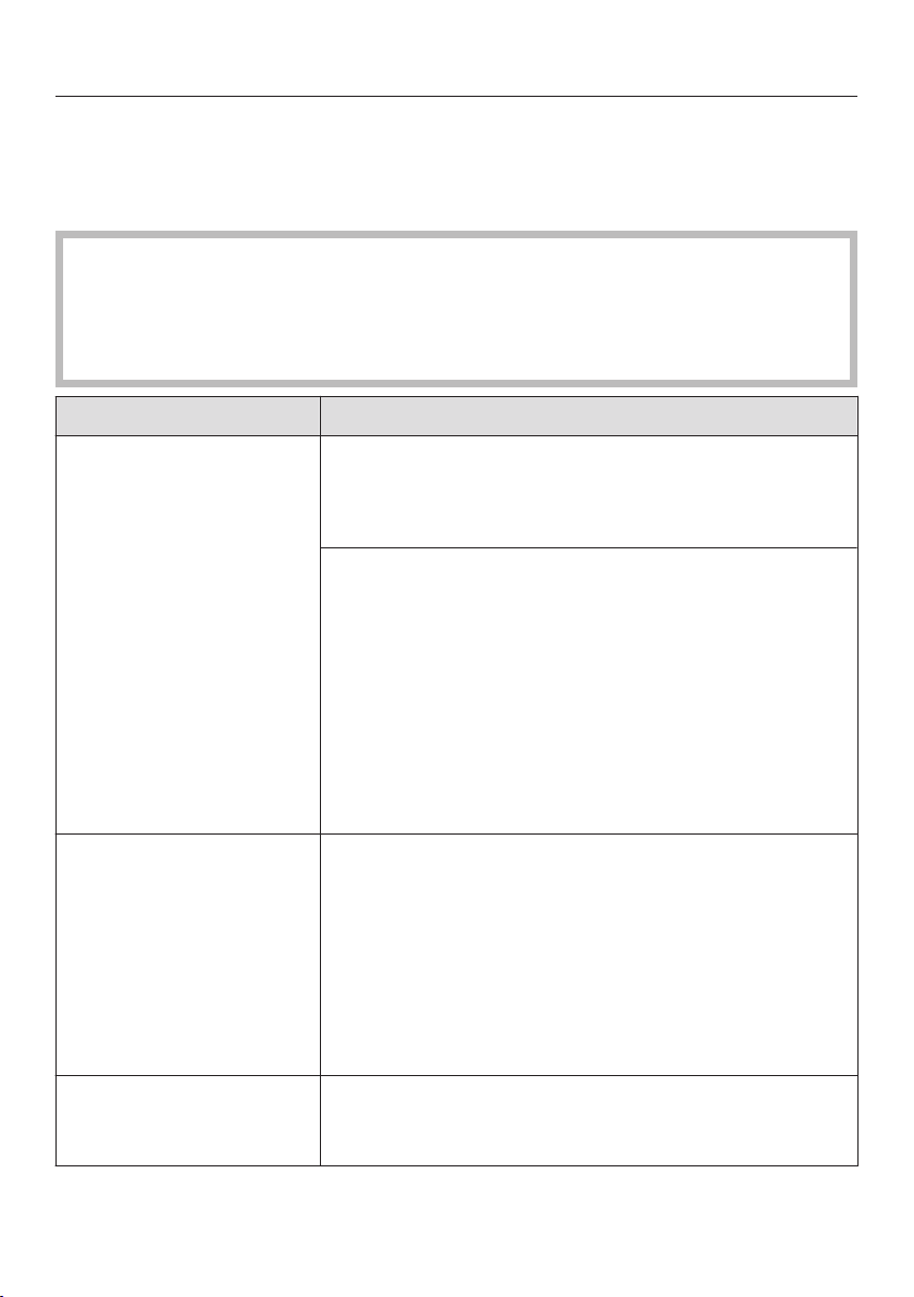
Problem Possible cause and solution
Cooktop or cooking
zones cannot be turned
on.
There is no power to the cooktop.
Chec
k if the circuit breaker has tripped. Contact
an electrician or Miele Service (for the minimum
fuse rating, see data plate).
There may be a technical fault.
Discon
nect the appliance from the electric power
supply for approx. 1 minute by
– tripping the relevant circuit breaker or screwing
the fuse out complet
ely, or
– tripping the ground fault circuit interrupter
(GFCI).
If,
after resetting/replacing the fuse or the GFCI, it
still will not turn on, contact a qualified electrician
or Miele Service.
There is a strange smell
or vapors when the ap‐
pliance is being used
for the first time.
Metal components are protected by a conditioning
agent. Smells and vapor may occur when the appli‐
ance is used for the first time. The smell and any va‐
p
ors do not indicate a faulty connection or a defective
appliance and are not harmful to your health. With
each subsequent use, the odor is reduced until it dis‐
appears completely. The smell and any vapors do not
indicate a faulty connection or a defective appliance
and are not harmful to your health.
Power levels 1 to 9
flash.
There is no or unsuitable cookware on the cooking
zone.
Use a suitable pan (see "Cookwar
e").
Frequently asked questions
49
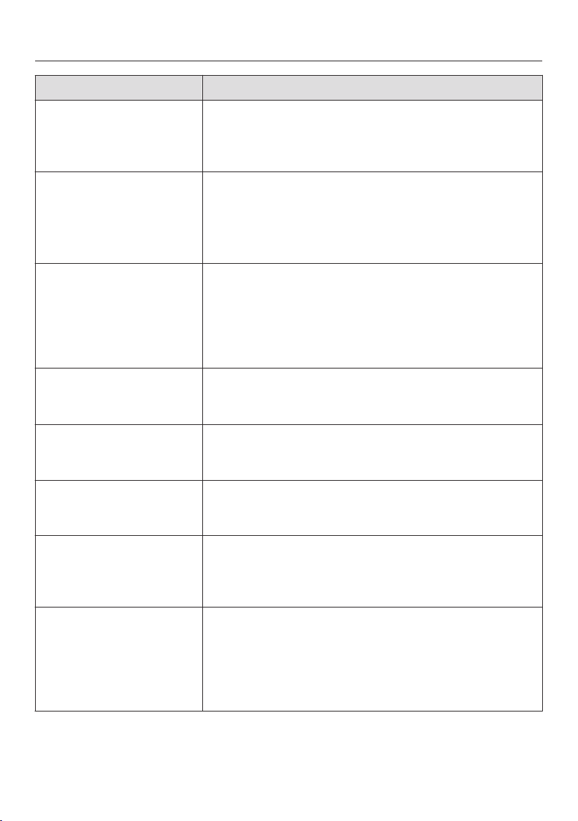
Problem Possible cause and solution
After the cooktop is ac‐
tivat
ed, appears in
the timer display for
several seconds.
The system lock or safety lock is activated.
D
eactivate the system lock or safety lock (see
"System lock / Safety lock").
flashes in the
timer display and
the c
ooktop
turns off auto‐
matically.
One or more of the sensor buttons are covered, for
example by fingers, food boiling over or by an object.
Clean
off any dirt or remove the object (see "Safe‐
ty shut-off").
After turning on the
cookt
op, appears in
the timer display for
several seconds. The
cooking zones don't
heat up.
The cooktop is in demo mode.
D
eactivate demo mode (see "Programming").
A burner switches itself
off aut
omatically.
A burner might have been operated for too long.
Y
ou can use the burner again by switching it back
on (see "Safety switch-off").
A cooking zone or the
whole cookt
op turns off
automatically.
The overheat protection was triggered.
See "O
verheat protection."
The booster has auto‐
matically switched off
early
.
The overheat protection was triggered.
See "O
verheat protection".
The burner is not work‐
ing in the usual way
with the set power lev‐
el.
The overheat protection was triggered.
See "
Overheat protection".
Power setting 9 is auto‐
matically r
educed if you
select power setting 9
on two linked burners
or extended zones at
the same time.
Operating both zones at power level 9 would exceed
the permitt
ed maximum power for the cooktop.
Use ano
ther burner that is not linked.
Frequently asked questions
50
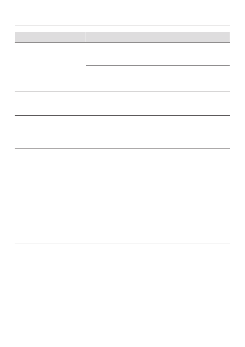
Problem Possible cause and solution
Auto Heat-up is turned
on, but the food does
not sta
rt cooking.
Large amounts of food are being heated.
S
tart cooking at the highest power level, then re‐
duce the power level manually.
The pan is not conducting heat properly.
Use a differ
ent pan that is able to better conduct
heat on an induction cooktop.
A noise can be heard
aft
er the appliance is
turned off.
The fan will continue running until the appliance has
coole
d down. It will then switch itself off automatical‐
ly.
One or more residual
heat indi
cators is flash‐
ing.
There was a power failure during operation or when
r
esidual heat was present.
You called the programming function while residual
h
eat was still present.
The sensor buttons are
ove
r-sensitive or do not
react at all.
The sensitivity level of the sensor buttons has
changed.
E
nsure that the cooktop is not in direct sunlight or
strong artificial light and that the area around the
cooktop is not too dark.
Make sure that there is nothing covering the sen‐
sor buttons or the cooktop.
Take any pans off the cooktop and wipe away any
food deposits.
I
nterrupt the power supply to the cooktop for ap‐
prox. 1 minute.
I
f the problem persists after power is restored,
please contact Miele Service.

Frequently asked questions
51
Problem Possible cause and solution
Alternating with a
number flashes
in the timer dis‐
play
.
Th
e overheat protection was triggered.
See "Overheat pr
otection."
or
The fan is blocked or defective.
Mak
e sure it has not been blocked by something
like a fork. Remove the cause of the blockage.
If
this fault message continues to appear in the
display, contact Miele Service.
and other numbers
Ther
e is a fault in the electronic module.
Int
errupt the power supply to the cooktop for ap‐
prox. 1 minute.
If
the problem persists after power is restored,
please contact Miele Service.

Con@ctivity
52
Your cooktop is communication ena‐
bled and can communi
cate with the
ventilation hood using the wireless USB
stick included with selected ventilation
hoods (Con@ctivity). The cooktop
sends information on its operating sta‐
tus to the ventilation hood. The opera‐
tion of the ventilation hood is automati‐
cally controlled by the power setting of
the connected cooktop.
If you want to log your cooktop onto
Con@ctivity, you must first log on
to
the ventilation hood.
Logging on the cooktop
When the cooking zone is turned
off, tap the and
sensor buttons
simultaneously until the indicator light
for the safety lock flashes.
In the timer display, (program) and
(status) appear. The program number
will be displayed to the left of the con‐
trol scales and the set status to the
right.
T
ap sensor button 1 on the rear left
control scale (set program 10).
T
ap sensor button 2 on the right
front control scale (set Status 2 =
log-on).
The log-on procedure starts and sensor
butt
on 2 flashes on the right front of the
control scale. The log-on procedure will
take a few minutes. Sensor button 2
lights up constantly as soon as the pro‐
cedure has been completed success‐
fully.
T
o save the setting, tap the sensor
button until the indicators go out.
Conclude the log-on on the hood/
display devices (see the corr
espond‐
ing instructions).
Logging off the cooktop
When the cooking zone is turned
off, tap the and
sensor buttons
simultaneously until the indicator light
for the safety lock flashes.
In the timer display, (
program) and
(status) appear. The program number
will be displayed to the left of the con‐
trol scales and the set status to the
right.
T
ap sensor button 1 on the rear left
control scale (set program 10).
T
ap sensor button 1 on the right
front control scale (set Status 1 =
log-off).
The log-off procedure starts and sensor
butt
on 1 flashes on the right front of the
control scale. The log-off procedure will
take a few minutes. Sensor button 1
lights up constantly as soon as the pro‐
cedure has been completed success‐
fully.
T
o save the setting, tap the sensor
button until the indicators go out.
IMPORTANT SAFETY INSTRUCTIONS - INSTALLATION
53
Installation and connection of
the
cooktop to the electrical power
supply may only be performed by a
qualified electrician.
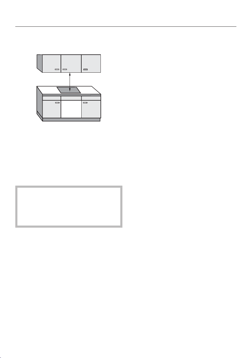
Install the upper cabinets and venti‐
lati
on hood before installing the
cooktop to avoid damaging it.
Reachi
ng over a hot cooktop
to access the cabinets can result
in burns. You can reduce the risk
of burns by installing a ventila‐
tion hood that extends at least
4 ³/₄" (12 cm) past the bottom of
the cabinets. Do not install any
cabinets above the cooktop.
The co
untertop must be heat-
resistant (up to 212°F / 100°C),
so that it does not become de‐
formed or the veneer detached.
The wall strips must be heat-re‐
sistant as well.
The co
oktop must not be in‐
stalled above refrigerators/freez‐
ers, dishwashers, or washer/
dryers.
This co
oktop may only be in‐
stalled above a stove or oven if
they have a built-in cooling fan.
Ensur
e that the power cord
cannot be touched after the
cooktop has been installed.
Aft
er the installation of the
cooktop, the electrical cord may
not come into contact with any
moving kitchen parts (e.g. a
drawer) or be subject to mechan‐
ical stress.
Ob
serve carefully the safety
clearances listed on the following
pages.
Safety clearances
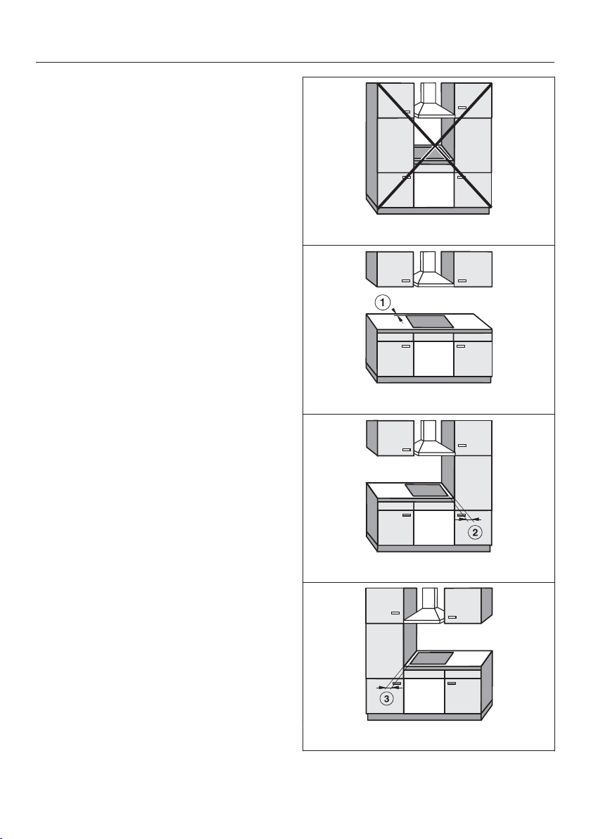
54
Safety clearance above the
cookt
op
For a ventilation hood above the cook‐
t
op, always use the clearance specified
by the hood manufacturer. If there are
no specifications from the hood manu‐
facturer or if flammable materials (e.g. a
utensil rail) are installed above the
cooktop, the clearance must be at least
30" (760 mm).
If there is more than one appliance
installed below the ventilation hood,
eac
h with a different safety clear‐
ance, the largest clearance must be
used.
Safety clearances
55
Safety clearances to the sides
and back of th
e cooktop
In installing a cooktop there may be an
optiona
lly high cabinet or room wall
against the rear side and one of the
sides (right or left) (see illustrations).
minimum distance between the
back of the count
er cut-out and the
rear edge of the counter:
2" (50 mm)
minimum distanc
e to the right of the
counter cut-out to the closest adjacent
piece of furniture (for instance, a high
cabinet) or a room wall:
2" (50 mm)
minimum distanc
e to the left of the
counter cut-out to the closest adjacent
piece of furniture (for instance, a high
cabinet) or a room wall:
2" (50 mm)
Not permitted!
Highly recommended!
Not recommended!
Not recommended!

Safety clearances
56
Minimum clearance under‐
neath the cookt
op
To ensure proper ventilation of the
coo
ktop, a minimum clearance is re‐
quired between the appliance and an
oven, protective base, or drawer.
The minimum clearance from the bot‐
t
om of the cooktop to
– the top of the oven must be ⁹/₁₆"
(15 mm).
– the top of the pr
otective base must
be ⁹/₁₆" (15 mm).
– bottom of the dr
awer must be 3"
(75 mm).
Protective base
Installation of a protective base under
the coo
ktop is allowed but not required.
A gap of 3" (75 mm) at the back is re‐
quir
ed for the power supply cord. For
better cooling of the cooktop, we rec‐
ommend a gap of 2" (50 mm) at the
front.
Safety clearances
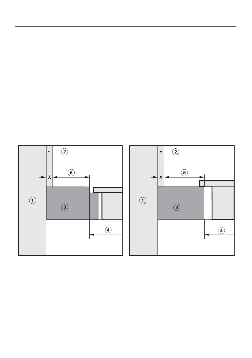
57
Safety distance from the wall covering
If a wall covering is installed, a minimum safety distance must be maintained be‐
tween the coun
tertop cut-out and the covering, since high temperatures can dam‐
age these materials.
If the covering is made of a combustible material (such as wood), the distance be‐
tween the coun
tertop cut-out and the wall covering must be a minimum of 2"
(50 mm).
For coverings made of non-combustible materials (such as metal, marble, granite,
cer
amic tiles) the minimum safety distance between the countertop cut-out and
the wall covering must be 2" (50 mm) minus the thickness of the covering. For ex‐
ample: thickness of wall covering 2" (50 mm) - ⁹/₁₆" (15 mm) = minimum safety
distance 1 ³/₈" (35 mm).
Flush-mounted cooktops Framed cooktops
Wall frame
Wall covering dimension x = thickness of the niche cladding
Countertop
Countertop cut-out
Minimum distance for
flammable mat
erials 2" (50 mm).
non-flammable mat
erials 2" (50 mm) - dimension x
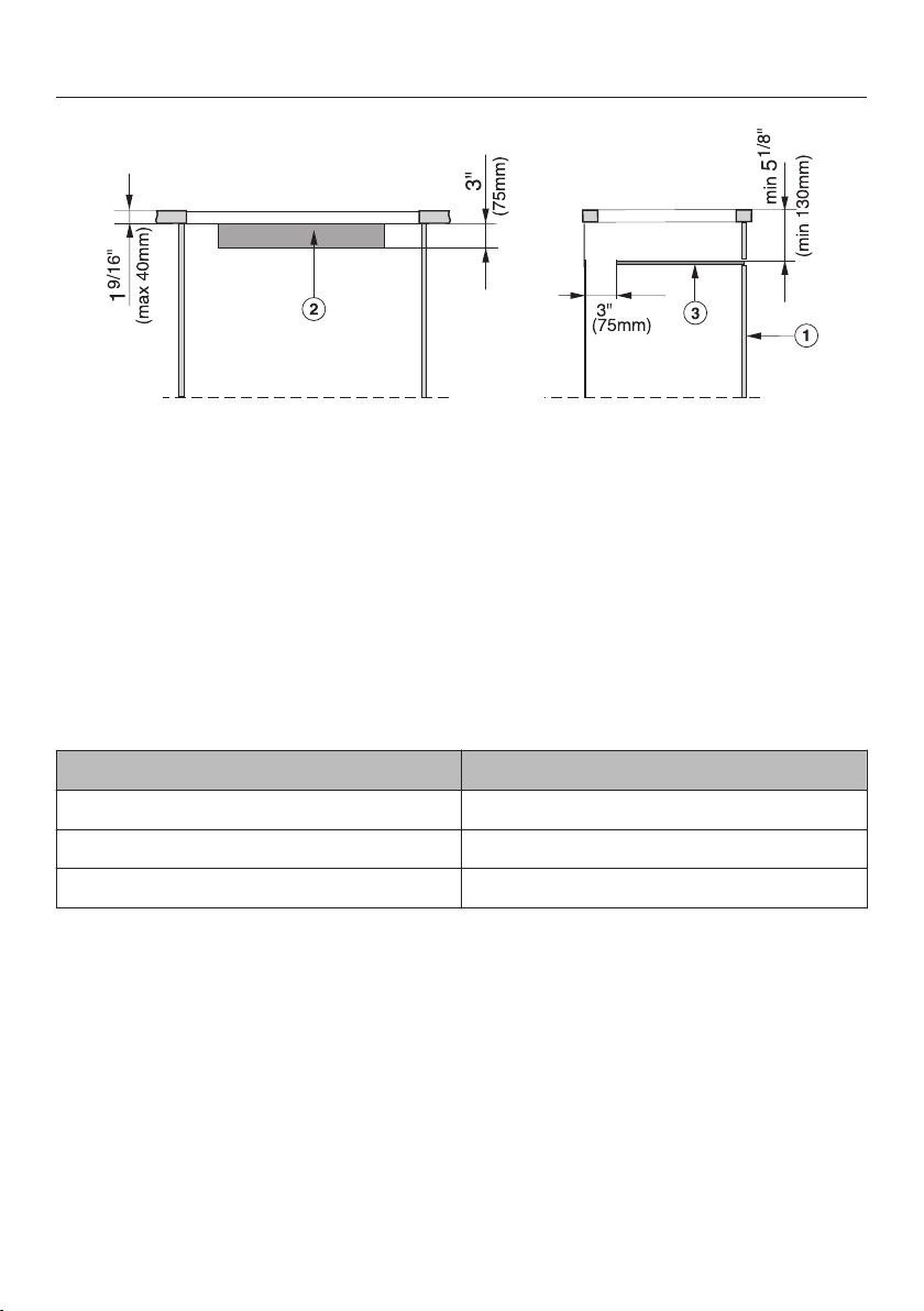
Ventilation
58
a
Front
b
Ventilation cut-out in the rear wall of the base unit
(Slight) ventil
ation also takes place when the base unit is directly against the
wall.
c
Protective base
The in
stallation of a protective base beneath the cooktop is not required, but
permitted.
If a protective base is installed, the distance between the top edge of the coun‐
tertop and the top edge of the base must be at least 5¹/₈" (130 mm) for proper
ventilation of the cooktop.
Leave an air gap of 3" (75 mm) at the back for the power cord.
Cooktop Dimensions of the ventilation cutout
KM 6360 / KM 6365 24¹/₂" x 3" (622 x 75 mm)
KM 6370 / KM 6375 30" x 3" (762 x 75 mm)
KM 6377 35¹/₂" x 3" (902 x 75 mm)
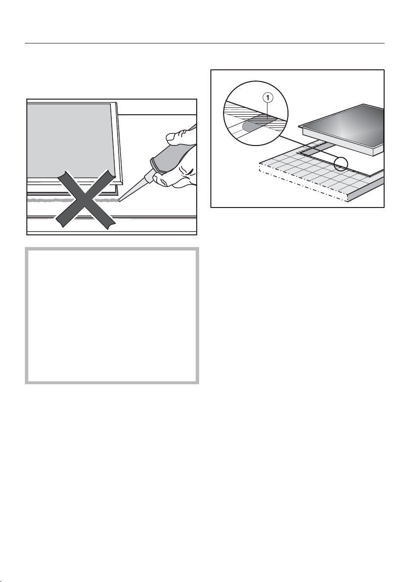
Framed cooktops
59
Instructions for installation
Seal between cooktop and counter
In case a disassembly is required,
the appliance must not be perma‐
nen
tly sealed into the countertop
when installed. The sealing strip un‐
der the edge of the appliance pro‐
vides a sufficient seal for the coun‐
tertop.
If the appliance is sealed into posi‐
tion, the countertop or appliance
could be damaged if it needs to be
removed for maintenance or service.
Tiled countertop
The grouting and shaded ar
ea under
the appliance frame must be flat and
even so that the frame will lie evenly
and the sealing strip under the edge of
the upper part of the appliance can
provide an adequate seal against the
countertop.
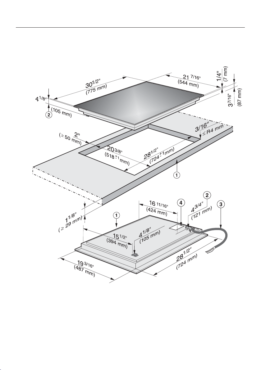
Framed cooktops
60
Installation dimensions
KM 6360
a
Front
b
Installation height
c
Flexible metal hose with power cord L = 3' 11¹/₄" (1200 mm)
d
Data plate
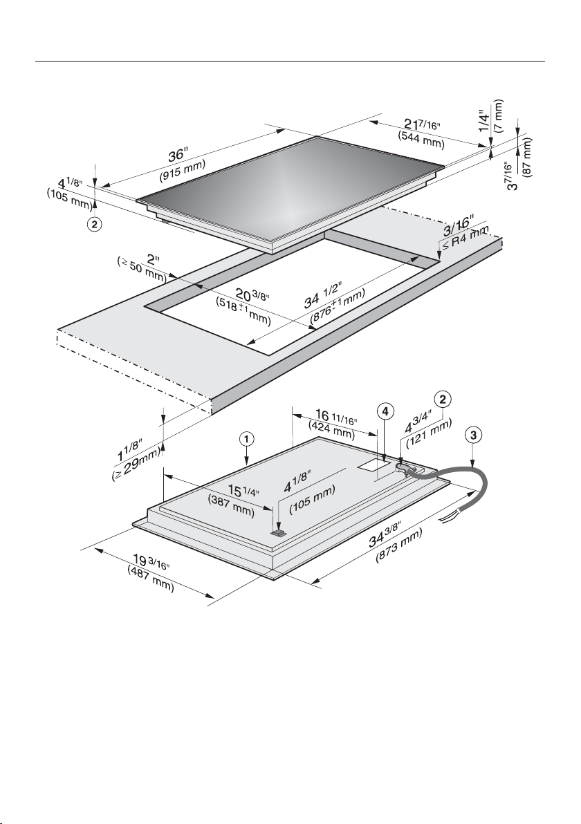
Framed cooktops
61
KM 6370
a
Front
b
Installation height
c
Flexible metal hose with power cord L = 3' 11¹/₄" (1200 mm)
d
Data plate
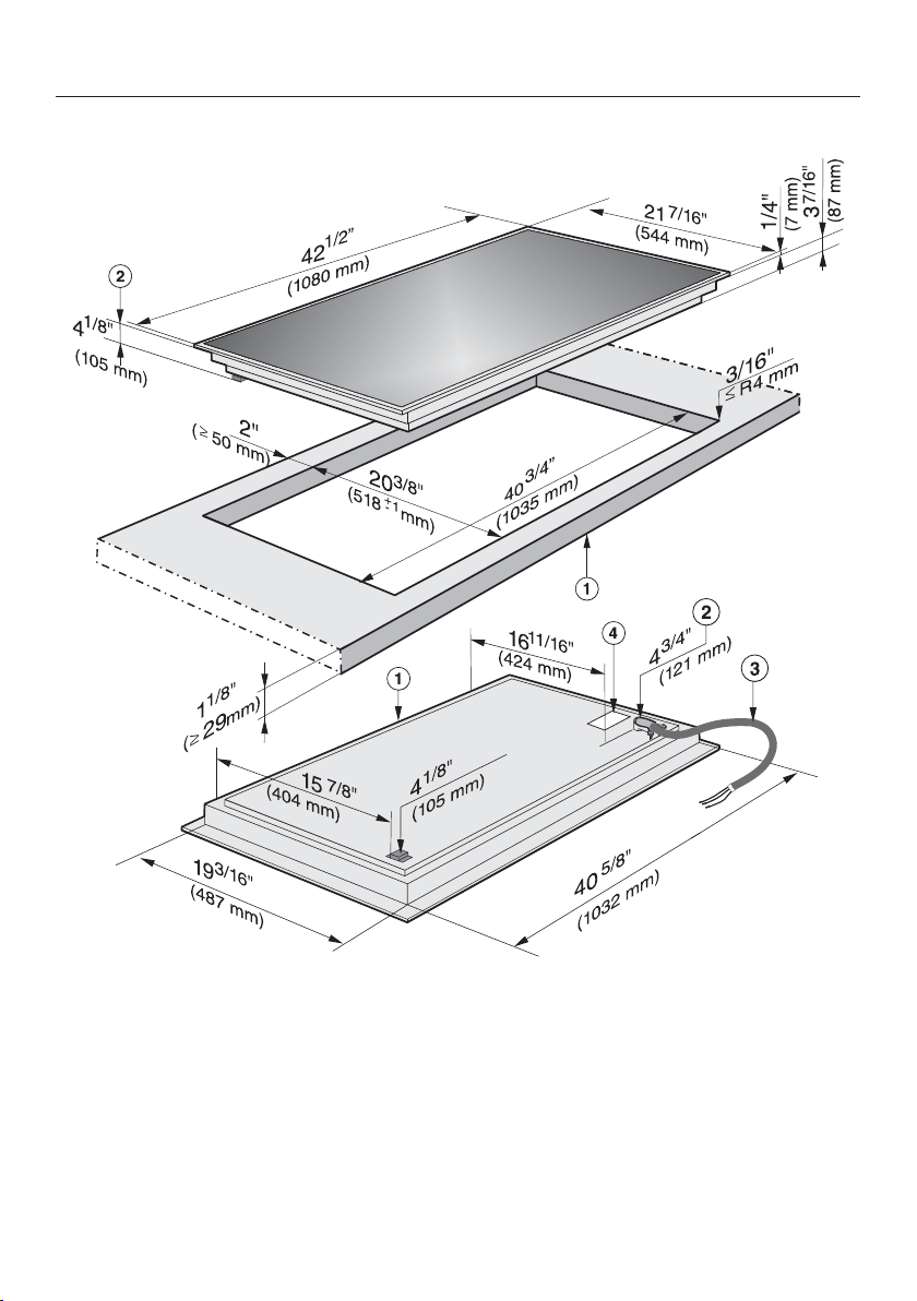
Framed cooktops
62
KM 6377
a
Front
b
Installation height
c
Flexible metal hose with power cord L = 3' 11¹/₄" (1200 mm)
d
Data plate

Framed cooktops
63
Installation
Preparing the counter
Cr
eate the counter cut-out as shown
in the cooktop diagram and in the de‐
tailed drawing. Remember to main‐
tain a minimum safety distance (see
"Safety clearances").
Seal an
y wooden counter surfaces
with a special varnish, silicone rub‐
ber, or resin to help prevent swelling
from moisture. The sealant must be
temperature resistant.
Ensure that the sealant does not get
on
the top surface of the countertop.
The sealing tape guarantees a non-
slipping seat of the co
oktop in the
cut-out. The gap between the frame
and counter reduces with time.
Installing the cooktop
F
eed the appliance power cord down
through the counter cut-out.
Cen
ter the cooktop in the cut-out.
Make sure that the seal under the
cooktop sits flush with the counter on
all sides. This is important to ensure
an effective seal.
NEVER seal the cooktop using addi‐
tio
nal sealing material such as sili‐
con!
If during installation the seal around
the fr
ame does not sit flush with the
countertop in the corners, the corner
radius, maximum 3/16" (4 mm), can
be carefully filed down to fit.
Co
nnect the cooktop to the electrical
power supply.
Che
ck that the cooktop works.

Flush-mounted (frameless) cooktops
64
Instructions for installation
Flush mounted cooktops are only suit‐
able
for installation in granite, marble,
tiled or solid wood counters. See "In‐
stallation dimensions" to check which
cooktop can be fitted into a glass
counter. For all other counter materi‐
als, consult the counter manufacturer
whether they can be used with a
flush-mounted cooktop.
The unobstructed width of the base
unit needs to be at least as wide as
the inner counter cut-out (see "Instal‐
lation dimensions") so that the cook‐
top is accessible from below and the
lower cabinet can be removed for
maintenance and servicing purposes.
If the cooktop is not accessible from
below after installation, the seal must
be removed in order for the cooktop
to be taken out.
The cooktop can be installed
– directly into a suitable cut-out in a
gr
anite or marble counter.
– into a suitable cut-out in a tiled or
sol
id wood counter with a wooden
support frame. The frame must be
provided on site, and is not supplied
with the appliance.
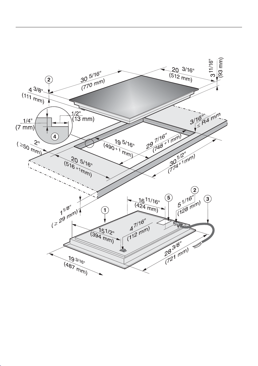
Flush-mounted (frameless) cooktops
65
Installation dimensions
KM 6365
a
Front
b
Installation height
c
Flexible metal hose with power cord,
L = 3' 11¹/₄" (1200 mm)
d
Data plate
Cut-out dimensions for granite or marble counters. Please take careful note
of the diagram.
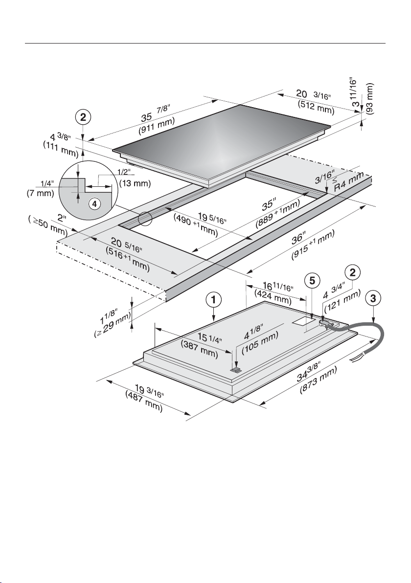
Flush-mounted (frameless) cooktops
66
KM 6375
a
Front
b
Installation height
c
Flexible metal hose with power cord,
L = 3' 11¹/₄" (1200 mm)
d
Data plate
Cut-out dimensions for granite or marble counters. Please take careful note
of the d
iagram.
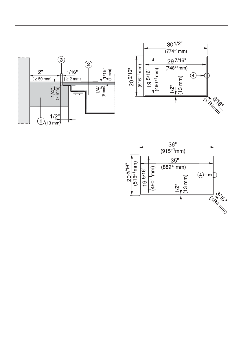
Flush-mounted (frameless) cooktops
67
Installation
Granite and marble counters
a
Countertop
b
Cooktop
c
Gap
As the ceramic glass slab and the
coun
ter cut-out have a certain dimen‐
sional tolerance, the width of the gap
(min. ¹/₁₆" [2 mm]) can vary.
KM 6365
d
Stepped cut-out
KM 6375
d
Stepped cut-out
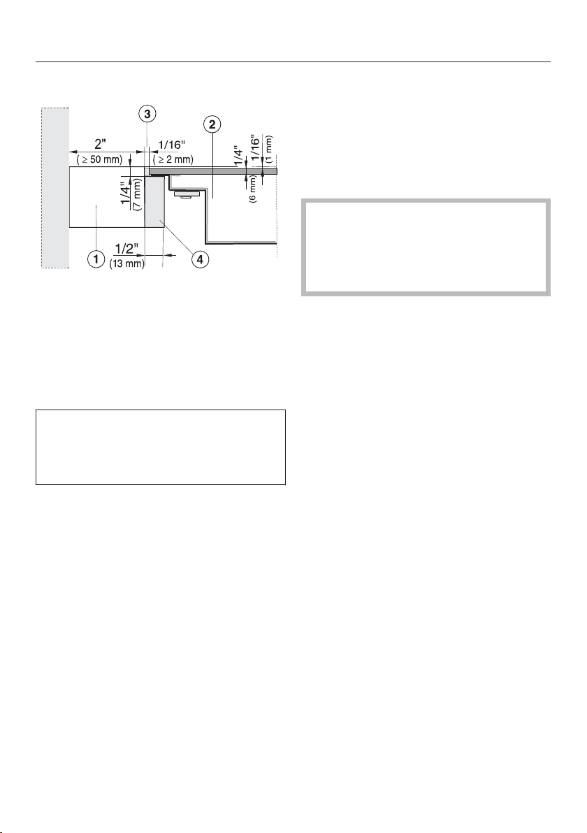
Flush-mounted (frameless) cooktops
68
Solid wood / tiled / glass counters
a
Countertop
b
Cooktop
c
Gap
d
Wooden frame ¹/₂" (13 mm) (not
supplied with appliance)
As the ceramic glass slab and the
coun
ter cut-out have a certain dimen‐
sional tolerance, the width of the gap
(min. ¹/₁₆" [2 mm]) can vary.
Preparing the counter
Mak
e the counter cut-out as shown
in the cooktop diagram and in the de‐
tailed drawing. Remember to main‐
tain a minimum safety distance (see
"Safety clearances").
Soli
d wood / Tile / Glass countertops:
Fix the wooden frame ¹/₄" (7 mm)
under the top edge of the counter
(see the figure).
Installing the cooktop
F
eed the appliance connection cable
down through the counter cut-out.
Cen
ter the cooktop in the cut-out.
Co
nnect the cooktop to the electrical
power supply.
Che
ck that the cooktop works.
Seal the r
emaining gap with a sili‐
cone sealant that is heat-resistant to
at least 320°F (160°C).
For granite and marble tiles, only use
silicone sealant that is specially for‐
mul
ated for granite and marble, and
observe the sealant manufacturer's
instructions.

Electrical connection
69
A
TTENTION:
Before installation or servicing, dis‐
connect the power supply by either
r
emoving the fuse, shutting off the
main power or manually "tripping"
the circuit breaker.
Installation work and repairs should
on
ly be performed by a qualified
technician in accordance with all ap‐
plicable codes and standards. Re‐
pairs and service by unqualified per‐
sons could be dangerous and the
manufacturer will not be held re‐
sponsible.Installation, repair, and
maintenance work should only be
performed by a Miele-authorized
service technician. Work by unquali‐
fied persons can cause considerable
danger to users. Miele cannot be
held liable for any damage arising as
a result of such work.
Before connecting the appliance to
the power supply, mak
e sure that the
voltage and frequency listed on the
rating label correspond with the
household electrical supply. This da‐
ta must correspond to prevent appli‐
ance damage.
Consult an electrician if in doubt.
For safety reasons, the cooktop may
only be used when it has been fully
in
stalled into the countertop.
To guarantee the electrical safety of
this appliance, continuity must exist
between the appliance and an effec‐
tive grounding system. It is impera‐
tive that this basic safety require‐
ment be met. If there is any doubt,
have the electrical system of the
house checked by a qualified electri‐
cian.
Installation, repair and maintenance
work shou
ld only be performed by a
Miele-authorized qualified electrician
in compliance with local regulations
and the ANSI National Electrical
Code / NFPA 70 in the United States
or the Canadian Electrical Code, Part
I in Canada (CSA standard C22.1).
Installer:
Please leave these instructions with
the cust
omer.

Electrical connection
70
Connection
Ensu
re that the connection data on
the data plate (voltage, frequency,
and fuse rating) match those of your
electrical supply.
The data plate is located underneath
the c
ooktop.
The cooktop is approved and ready for
co
nnection to a grounded connector
with three connecting wires, sheathed
by a flexible metal hose.
It must be connected to an assigned
line in an approved connecting socket.
The appliance must be able to be dis‐
co
nnected from the power supply on all
poles by disconnecting devices! (When
turned off, a contact distance of at least
¹/₈" (3 mm must be present!) The dis‐
connecting devices are overcurrent pro‐
tection elements and protective circuit
breakers.
Black: Connect to L1 (hot)
Red: Connect to L2 (hot)
Green: Connect to GND (ground)
KM 6360 / KM 6365
208/240 V
, 60 Hz, 40 A
KM 6370 / KM 6375 / KM 6377
208/240 V
, 60 Hz, 50 A
Make sure that the connecting socket is
accessible aft
er the installation of the
cooktop.
Further information can be found on the
included d
ata plate.
WARNING:
THIS COOKTOP MUST BE
GROUNDED

Caring for the environment
71
Disposal of the packing mate‐
rial
The cardboard box and packing materi‐
als pr
otect the appliance during ship‐
ping. They have been designed to be
biodegradable and recyclable.
Ensure that any plastic wrappings,
bags, etc. ar
e disposed of safely and
kept out of the reach of children. Dan‐
ger of suffocation!
Disposal of your old appliance
Old electrical and electronic appliances
oft
en still contain valuable materials.
However, they also contain harmful
substances that were essential for the
proper functioning and safe use of the
equipment. Handling these materials
improperly or disposing of them in your
household waste can be harmful to
your health and the environment.
Therefore, please do not dispose of
your old appliance with regular house‐
hold waste.
Old appliances may contain materials
that can be recycled. Please contact
your local recycling authority about the
possibility of recycling these materials.
Please be sure that your old appliance
do
es not pose a danger to children
while being stored for disposal.

Technical service, data plate, warranty
72
After sales service
In the event of a fault which you cannot easily correct yourself, please contact:
– your Miele dealer, or
– the Miele Technical Service Department.
See back cover for contact details.
Please quote the model and serial number of your appliance when contacting
Miele.
Data plate
Adhere the extra data plate supplied with the appliance here. Ensure that the mod‐
el number is the same as the on
e on the back of these operating instructions.
Warranty
For further information, please refer to your warranty booklet.

MieleCare
73
This service is available in USA only.
MieleCare, our Ext
ended Service Con‐
tract program, gives you the assurance
of knowing that your appliance invest‐
ment is covered by 5 years of worry
free ownership.
MieleCare is the only Extended Service
Contract in the industry that guarantees
repairs by a Miele Authorized Service
Provider using genuine Miele parts. On‐
ly genuine Miele parts installed by fac‐
tory trained professionals can guaran‐
tee the safety, reliability, and longevity
of your Miele appliance.
Please note that unless expressly ap‐
pr
oved in writing by Miele’s Service de‐
partment, Extended Service Contracts
offered by other providers for Miele
products will not be recognized by
Miele. Our goal is to prevent unauthor‐
ized (and untrained) service personnel
from working on your Miele products,
possibly doing further damage to them,
you and/or your home.
To learn more about MieleC
are Extend‐
ed Service Contracts, please contact
your appliance dealer or visit us online
at:
www.mieleusa.com/mielecare

9 Independence Way
Princeton, NJ 08540
Phone:
Fax:
www.mieleusa.com
U.S.A.
Miele, Inc.
National Headquarters
Please have the model and serial number
of your appliance available before
contacting Technical Service.
Canada
Importer
Miele Limited
Headquarters and Miele Centre
800-843-7231
609-419-9898
609-419-4298
Technical Service & Support
Nationwide
Phone:
Fax:
161 Four Valley Drive
Vaughan, ON L4K 4V8
www.miele.ca
800-999-1360
888-586-8056
Customer Care Centre
Phone:
800-565-6435
905-532-2272
Germany
Manufacturer
Miele & Cie. KG
Carl-Miele-Straße 29
33332 Gütersloh
74

M.-Nr. 09 888 630 / 02en-US
KM 6360 / KM 6365 / KM 6370 / KM 6375 / KM 6377