Loading ...
Loading ...
Loading ...
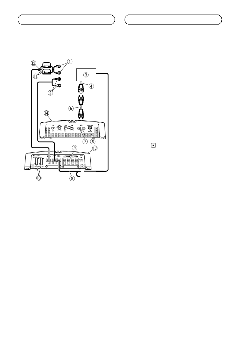
Connection diagram
1 Special red battery wire
RD-223 (sold separately)
After completing all other amplifier connec-
tions, finally connect the battery wire terminal
of the amplifier to the positive + battery term-
inal.
2 Ground wire (Black)
RD-223 (sold separately)
Connect to metal body or chassis.
3 Car stereo with RCA output jacks (sold sepa-
rately)
4 External output
5 Connecting wire with RCA pin plugs (sold se-
parately)
6 Speaker input terminal (use a connector in-
cluded)
Please see the following section for speaker
connection instructions. Refer to Connections
when using the speaker input wire.
7 RCA input jack
8 System remote control wire (sold separately)
Connect male terminal of this wire to the sys-
tem remote control terminal of the car stereo.
The female terminal can be connected to the
auto-antenna relay control terminal. If the car
stereo lacks a system remote control terminal,
connect the male terminal to the power term-
inal via the ignition switch.
9 Speaker output terminals
Please see the following section for speaker
connection instructions. Refer to Connecting
the speakers.
a Fuse 30 A × 2 (GM-A5702) / 25 A × 1 (GM-
A3702)
b Fuse (30 A) × 2
c Grommet
d Rear side
e Front side
En
Connecting the units
5707000011330S <8>
Loading ...
Loading ...
Loading ...