Loading ...
Loading ...
Loading ...

27
1000 SERIES UTOPIA
User manual
EN
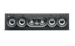
1000 IWSUB UTOPIA
1. Connect the pre-stripped loudspeaker wire to the loudspeaker's spring-loaded terminals. It is essential that the connection
polarity for each loudspeaker is correct: the cable connected to the '+' terminal on the amplifier must be connected to the red
terminal on the loudspeaker. Likewise, the cable connected to the '-' terminal on the amplifier must be connected to the black
terminal (fig. B3).
1000 IWSUB UTOPIA allows you to have two different impedances depending on your desired assembly, 8 ohms or 72 ohms. You
can select these impedances by changing the position of the 4 'straps’. It is important that all the ‘straps’ are in the same position
and that they are always connected to the loudspeakers. To optimise the impedance in line with your amplifier's capacity, you can
also mix parallel and serial assembly of the IWSUBs. To do this, you will need an additional speaker driver cable.
2. Insert the product into the wall by pressing on each side of the loudspeaker to ensure it is in place (fig. B4). Products from the
1000 Series are heavy, and it is therefore essential that they are installed by a specialist.
3. Lock all the mounting brackets using the Allen key supplied (fig. B5). Make sure the brackets are snug against the internal
partition of your wall.
4. Peel off the tape from the adhesive on the grille seals, then stick the seals onto the ends of the grilles (fig. B6). The seals will stick
after a few seconds (fig. B6). In the vertical position, select the seal with the vertical logo; the Focal logo will always be located at
the bottom of the product. In the horizontal position, select the seal with the horizontal logo; the logo will be on the right of the
product.
5. The grille can now be fitted. The grille is held onto the mounting frame magnetically, which means you only need to align it with
the edge of the mounting frame (fig. B7). Self-adhesive felt is used so that the product blends more seamlessly into your interior.
You can also choose not to stick felt onto your grilles, for perfect sound reproduction. A grille positioned incorrectly on the product
may vibrate and negatively impact the listening experience. Make sure the grille is correctly positioned on the loudspeaker’s metal
frame. NB: the felt may peel off while you are handling the grille.
1000 IWLCR UTOPIA & 1000 IWSUB UTOPIA assembly
1. Unscrew the top strip of 1000 IWSUB UTOPIA using a screwdriver (fic. C1). The top strip is always marked ‘FOCAL UTOPIA’.
2. Insert and screw the two dividers onto the top of the 1000 IWSUB UTOPIA (fig. C2).
3. Insert the product into the wall by pressing on each side of the loudspeaker to ensure it is in place (fig. C3). Products from the
1000 Series are heavy, and it is therefore essential that they are installed by a specialist. 1000 IWSUB UTOPIA allows you to have
two different impedances depending on your desired assembly, 8 ohms or 72 ohms. You can select these impedances by changing
the position of the 4 'straps’. It is important that all the ‘straps’ are in the same position and that they are always connected to the
loudspeakers. To optimise the impedance in line with your amplifier's capacity, you can also mix parallel and serial assembly of the
IWSUB UTOPIA and IWLCR UTOPIA (fig. F/G). To do this, you will need an additional speaker driver cable.
4. Connect your amplifier to the main 1000 IWLCR UTOPIA loudspeaker (fig. C5).
5. Connect the 1000 IWLCR UTOPIA and 1000 IWSUB UTOPIA products, using the Speakon cable supplied (fig. C5).
6. Press the product up against the partition of your wall and lock it using the key supplied (fig. C6). The 1000 Series UTOPIA
products are heavy and generate strong vibrations, so make sure you use a professional to install them.
7. You can repeat these operations when assembling other 1000 IWSUB UTOPIA products with your other products.
8. The grilles need to be prepared using the connections and grille dividers supplied (fig. C7). Peel off the tape from the adhesive
and position the connection or divider on the grilles. The glue holds within a few seconds, with sufficient pressure exerted on the
product.
9. The grille can now be fitted. The grille is held onto the mounting frame magnetically, which means you only need to align it with
the edge of the mounting frame (fig. C8). Self-adhesive felt is used so that the product blends more seamlessly into your interior.
You can also choose not to stick felt onto your grilles, for perfect sound reproduction. A grille positioned incorrectly on the product
may vibrate and negatively impact the listening experience. Make sure the grille is correctly positioned on the loudspeaker’s metal
frame. NB: the felt may peel off while you are handling the grille.
Product assembly
1000 Series UTOPIA products are assembled using the Speakon cable supplied. This cable allows you to connect products to each
other. If the IWSUB UTOPIAs are assembled as a series, you will need an additional cable. When 1000 Series UTOPIA products are
assembled as a series, we advise that you follow the recommendations (fig. F). To optimise the performance of your system, you
need to disassemble the Speakon cable supplied to retrieve the red or black wire (fig. F); this wire connected to the Speakon cable
will be connected to the terminal board (‘+’ or ‘-’) of the IWSUB UTOPIA loudspeaker (fig. F).
Paint
If you wish, you can paint the grille on your products, the strips and grille dividers, so that your product is coordinated with your
environment. We recommend that you firstly remove the grille and paint it using a paint gun. The paint used can be the same type
as the paint used on the walls (fig.D/E). If you wish to paint the ceiling/wall without disassembling your product, we recommend
that you use the protective mask supplied. It is magnetically attached to the mounting frame (fig. D/E).
Loading ...
Loading ...
Loading ...