Installation Instructions
Instructions d'installation
KIT WIRING BOX
sku # number: WIREBOX

2
READ AND SAVE THESE INSTRUCTIONS BEFORE YOU START
INSTALLING THIS RANGEHOOD
WARNING: - TO REDUCE THE RISK OF FIRE, ELECTRIC SHOCK, OR INJURY TO PER-
SONS, OBSERVE THE FOLLOWING:
a)Installationworkandelectricalwiringmustbedonebyqualiedperson(s)inaccordance
withallapplicablecodesandstandards,includingre-ratedconstruction.
b) When cutting or drilling into wall or ceiling, do not damage electrical wiring and other
hiddenutilities.
CAUTION: - To reduce The Risk Of Fire and Electric Shock, this Rangehood Wiring Box
Kit shall be used only with Faber Rangehood Models that have been investigated and
foundacceptableforusewiththisKit.Seehoodmanualtodeterminecompatibility.
3
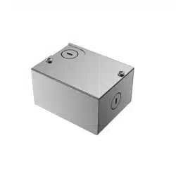
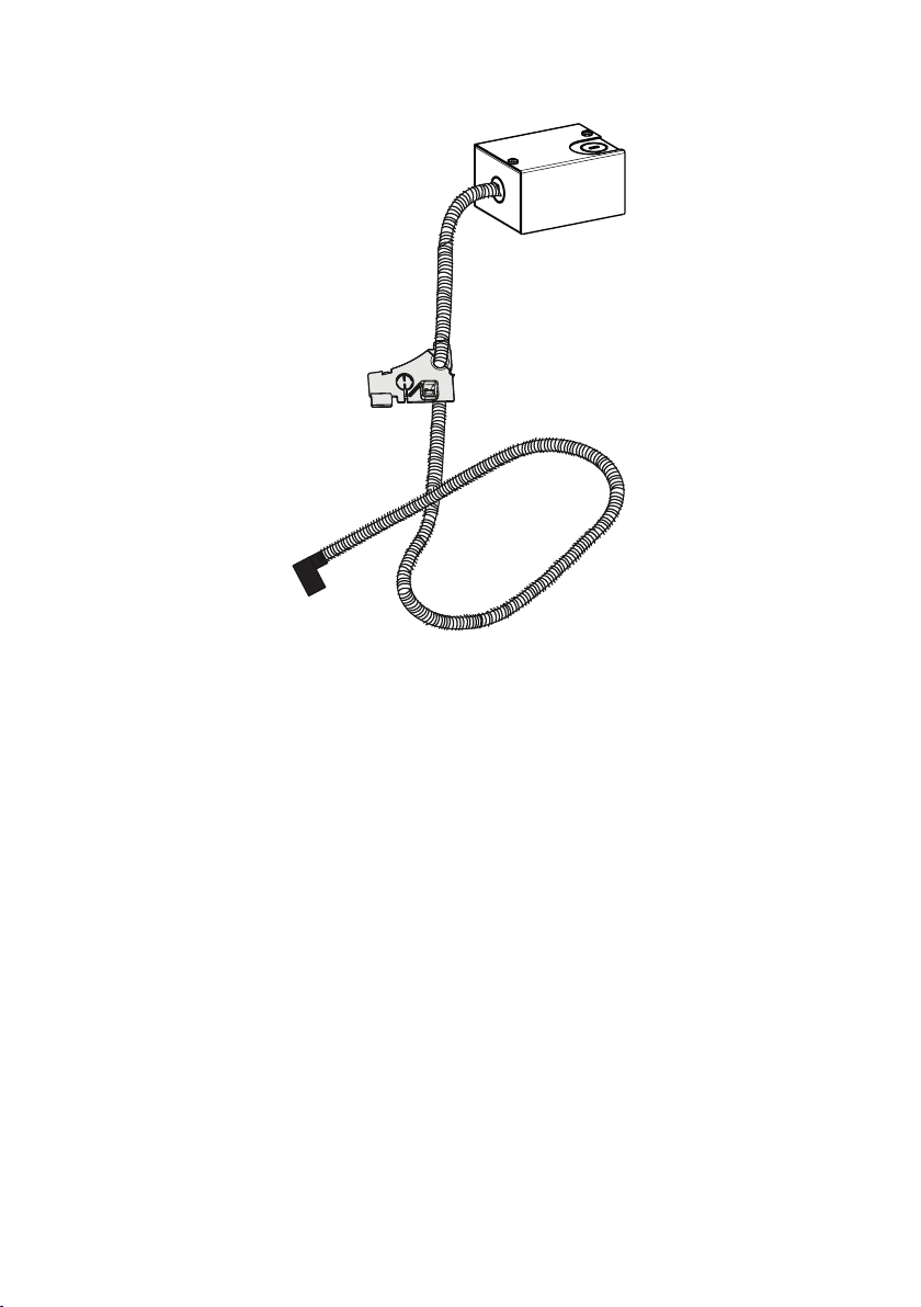
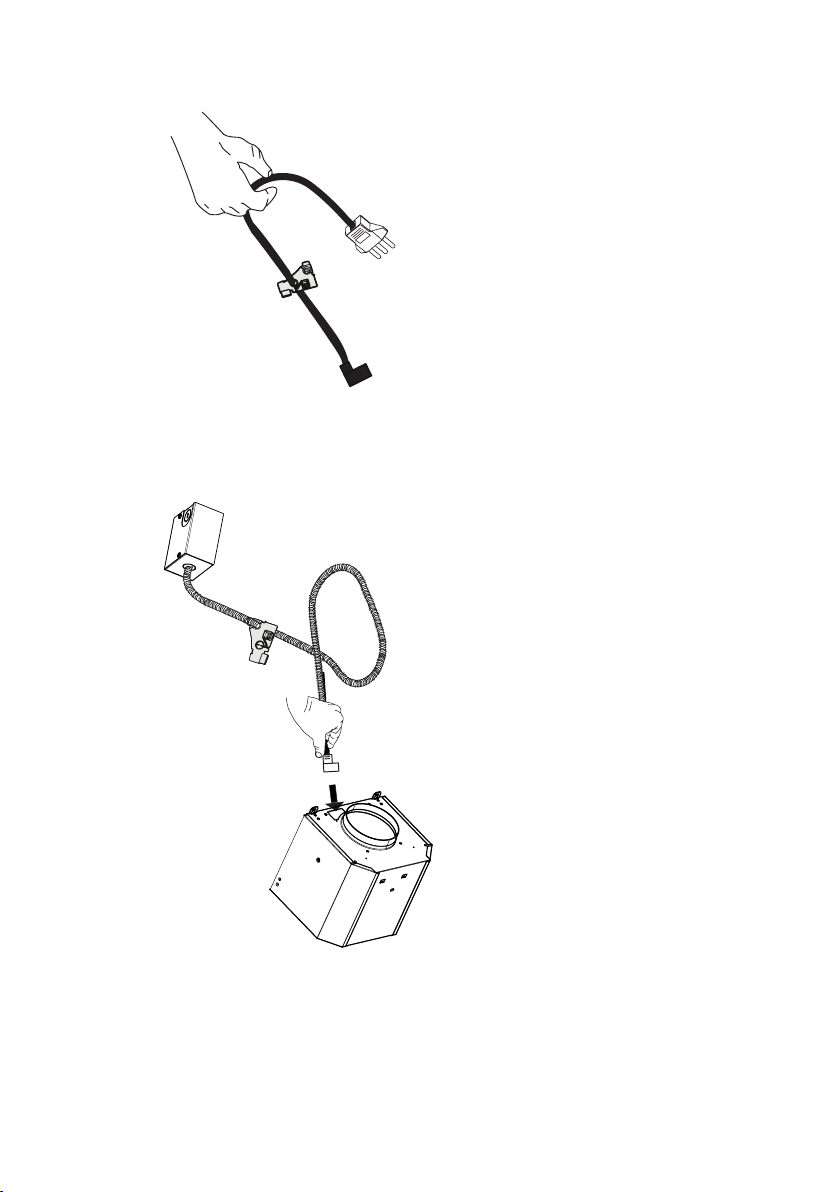
MAIN PARTS
Wiring Box
Motor
Connector
Fair lead
Cable and
sheath

4
1
For Rangehoods
with an easy cube,
disconnect the
power cable from
the motor inside
the motor box.
For Rangehoods
without an easy
cube, disconnect
the power cable
from the motor
directly.
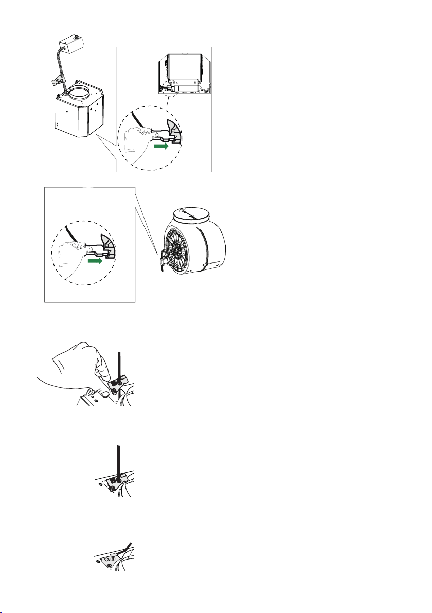
2
Remove the
ground lead from
the Rangehood by
using a at head
"screwdriver".
5
3
4
Remove the
Power Cable with
grounded lead and
Connector from the
Rangehood.
For Rangehoods
with an easy cube,
insert the motor
connector in the
wiring hole where
the previous wire
was taken out.
For Rangehoods
without an easy
cube, insert the mo-
tor connector in the
wiring hole on top
of the hood body
where the previous
wire was taken out.
6
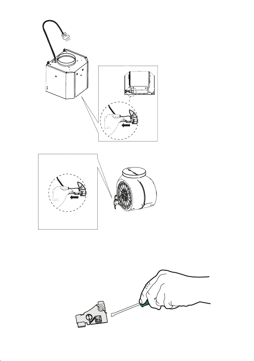
Reconnect the Motor Con-
nector to the blower (both
types shown).
A
B
C
5
6
Install the new ground lead
in the same position where
we removed it previously.
7
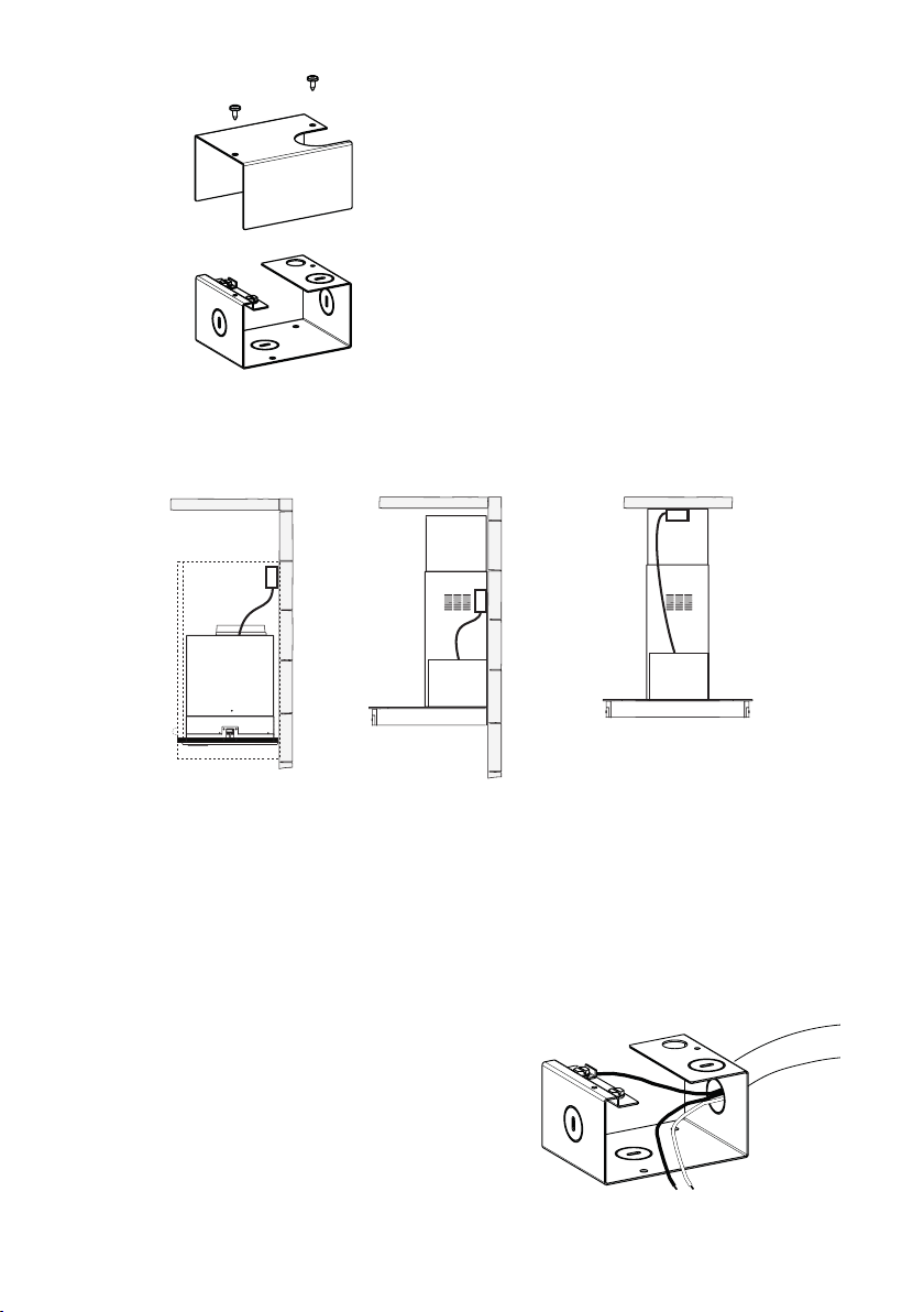
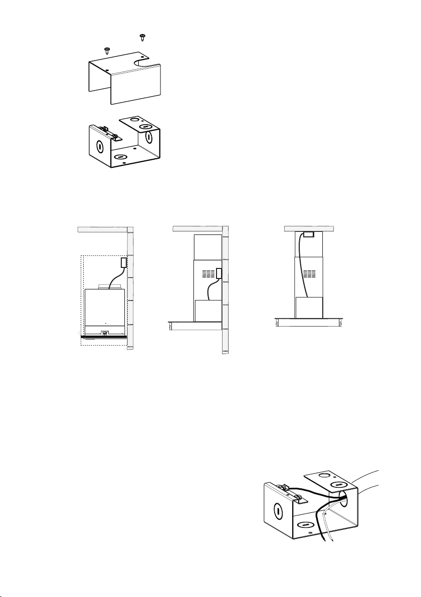
The Wiring Box can be installed on the wall, in the cabinet, or in the ceiling depending on
the specic rangehood model and power connection in the house.
Mark the chosen location at the centers of the holes of the Wiring Box and secure using
wall plugs (purchased separately) and the screws provided with the kit.
7
8
Open the Cover of Wiring
Box by unscrewing the two
screws.
9
Connect the Power Supply Cable to the range-
hood. Attach the White lead of the power supply
to the White lead of the rangehood with a twist-
on type wire connector. Attach the Black lead of
the power supply to the Black lead of the range-
hood with a twist-on type wire connector (C).
Connect the Green (Green and Yellow) ground
wire under the Free Green grounding screw.

8
VEUILLEZ LIRE ET CONSERVER LA PRÉSENTE NOTICE
AVANT DE COMMENCER L'INSTALLATION DE LA HOTTE
DE CUISINE
AVERTISSEMENT:-POURRÉDUIRELESRISQUESD'INCENDIE,DECHOC
ÉLECTRIQUEOUDEBLESSURECORPORELLE,RESPECTEZLESINSTRUC-
TIONSSUIVANTES:
a)L'installation et le branchement électrique doivent être réalisés par un
technicienqualiéetconformémentàtouslescodesetnormesenvigueur,
incluantceuxconcernantlaconstructionàl'épreuvedufeu.
b)Lorsquevousfaitesuneouvertureoupercezdansunmurouleplafond,veillez
ànepasendommagerleslsélectriquesoud'autresdispositifscachés.
ATTENTION : -Pour réduirele risqued'incendie oude chocélectrique, la
présentetrousseboîtierdeconnexiondoitêtreutiliséeexclusivementavec
lesmodèlesdehottesFaberdontlacompatibilitéaveccettetrousseaété
vériée.Reportez-vousaumanueldelahottepourdéterminerlacomptabilité.

9
PIÈCES PRINCIPALES
Boîtier de
connexion
Connecteur du
moteur
Élément de mise
à la terre
Câble et
gaine
10
1
2
Pour les hottes
équipées d'un
Easy Cube, dé-
branchez le câble
d'alimentation du
moteur à l'intérieur
du boîtier du
moteur.
Pour les hottes
sans Easy
Cube, débran-
chez le câble
d'alimentation
directement du
moteur.
Enlevez l'élément
de mise à la terre
de la hotte à l'aide
d'un tournevis à
lame plate.

11
3
4
Enlevez le câble
d'alimentation avec
l'élément de mise
à la terre et le con-
necteur de la hotte.
Pour les hottes
équipées d'un
Easy Cube, insérez
le connecteur
du moteur dans
l'ouverture de
câblage d'où le l
précédent a été
enlevé.
Pour les hottes
sans Easy Cube,
insérez le con-
necteur du moteur
dans l'ouverture de
câblage d'où le l
précédent a été tiré,
au sommet du bâti
de la hotte.

12
A
B
C
5
6
Rebranchez le connecteur
du moteur au ventilateur
(deux types illustrés).
Installez le nouvel élément
de mise à la terre à la même
position d'où il a été enlevé
précédemment.
13
Le boîtier de connexion peut être installé sur le mur, dans une armoire ou au plafond, en
fonction du modèle de hotte et de l'alimentation électrique de la maison.
Tracez un repère au centre des trous à l'emplacement choisi pour le boîtier de connexion
et xez-le à l'aide de chevilles (achetées séparément) et des vis fournies avec la trousse.
7
8
Ouvrez le couvercle du
boîtier de connexion en
dévissant les deux vis.
9
Branchez le câble d'alimentation à la hotte.
Branchez le l blanc de l'alimentation au l
blanc de la hotte à l'aide d'un connecteur
verrouillé par rotation. Branchez le l noir de
l'alimentation au l noir de la hotte à l'aide d'un
connecteur verrouillé par rotation (C). Branchez
le l vert (vert et jaune) de mise à la terre sous la
vis libre de mise à la terre verte.

14

15

991.0441.098_02 - 160823
D002519_01