READ IT OR WATCH IT
Read instructions or watch easy-to-follow video.
Scan QR code or visit bit.ly/2J1IM4f
45744, 45745
PREMIUM RECESSABLE
LED PUCK LIGHTS
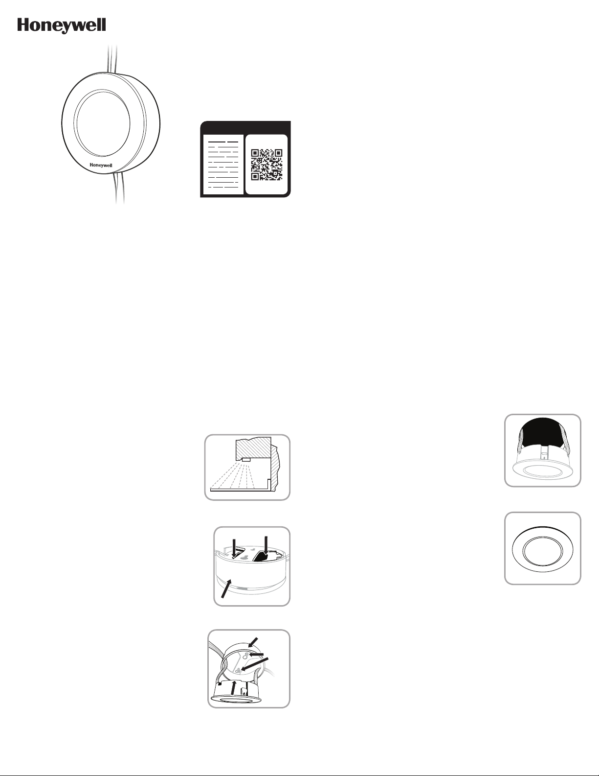
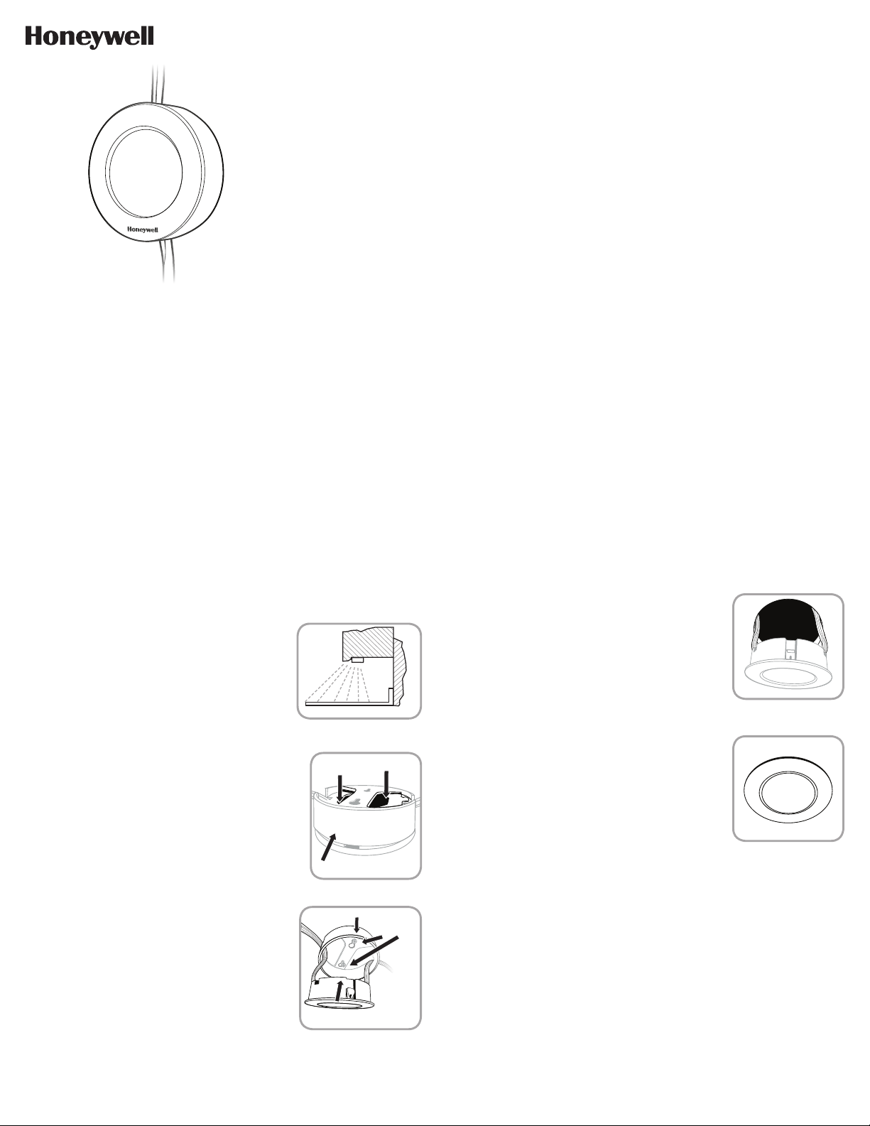
FIGURE 1
FIGURE 3
CABINET
COUNTER TOP
WALL
FIGURE 2
SAVE THESE INSTRUCTIONS FOR POSSIBLE FUTURE USE.
TO ADD ADDITIONAL PUCK LIGHTS, SEE MANUAL FOR
45739 - PREMIUM RECESSABLE LED PUCK LIGHTS EXPANSION PACK
IMPORTANT SAFETY INSTRUCTIONS
This portable light has a polarized plug (one blade is wider than the other) to reduce the risk of
electric shock. This plug fits in a polarized outlet only one way. If the plug does not fit fully in the
outlet, reverse the plug. If it still does not fit, contact a qualified electrician. Never use with on
extension cord unless plug can be fully inserted. Do not alter the plug. Read entire installation
instructions before you begin.
INSTALLATION INSTRUCTIONS
Carefully plan out your installation prior to securing your lights to the mounting surface or drilling
any holes for recessed mounting. Be sure to consider distances to make sure pucks will
interconnect via linking cords and that the 5ft. power cord will reach the nearest electrical outlet.
For kitchen installations, the recommended mounting for LED puck lights is near the front lip of
your kitchen under cabinets as shown in Figure 1. This provides the best light distribution across
a countertop.
PUSH ON BACK OF PUCK
GRASP TRIM RING
TRIM RING
MOUNTING
SCREWS
PUSH
PUCK INTO
MOUNTED
TRIM RING
FIGURE 4
1. DO NOT ATTEMPT TO INSTALL FIXTURE WHILE
PLUGGED IN.
2. Select a suitable dry mounting location (indoor only).
Make sure mounting surface is capable of supporting
the LED puck light.
3. Locate positions where the puck should be mounted.
(Keep in mind linking cords.)
4. Remove trim ring by firmly grasping ring and then firmly
pushing on back side of puck as shown in Figure 2.
5. For recessed mount applications, skip to Step 17. For
surface mount applications, continue with Steps 616.
6. Using the trim ring as a template, mark the locations of
the mounting holes on the mounting surface. Be sure to
orient the trim ring openings for routing linking cords.
7. Pre-drill holes in the mounting surface with a 1/16in.
(1.5mm) drill bit for soft woods and 3/32in. (2.4mm) drill
bit for hard woods.
8. Secure the trim ring with the mounting screws (included),
keeping the power cables threaded through trim ring
openings.
9. Secure the puck in the trim ring by firmly pushing the
puck into the trim ring while feeding the power cords
through the trim ring openings until the puck snaps into
place. See Figure 3.
10. The power cord has a molded plug on one end with an
in-line switch and a link connector at the other end.
The link connector plugs into the LED puck light link
connector. The two other cords provided are linking cords
with link connectors on both ends. These are used to
connect the initial LED puck to the next puck in a chain.
Link adjacent pucks only.
11. Attach the power cord link connector to the LED puck
light link connector of the initial puck installed closest to
the outlet.
12. Install the next puck close enough to the initial puck
for the 12in. link cord to reach the additional LED puck
light following Steps 19 of the mounting instructions.
13. Once installed, attach the linking cord between the initial
LED puck (previously installed) and the new LED puck.
14. Repeat steps 1213 for each additional LED puck in a
chain.
15. When adding an additional LED puck to an existing,
compatible, LED puck installation, the power cord (with
the power plug) is not needed. Only the first LED puck
in the chain needs to be connected to power with the
power cord. Connect a maximum of 40 pucks together.
16. Plug power cord power plug into a 120VAC 60Hz outlet.
Surface mount installation is complete.
17. For Recessed Mount Applications: Discard the trim ring.
It will not be needed in recessed mount applications.
18. Mark the locations of the puck lights on the mounting
surface with a pencil. Before you drill, be sure to consider
distances to make sure pucks will interconnect via linking
cables and that the power cord will reach the receptacle.
19. Using a power drill and 2 ½in. hole saw, drill mounting
holes for the LED puck lights.
20. Route cords of LED puck lights through the holes
(see Figure 4) and press puck light into mounting hole
until fully seated (see Figure 5).
21. Connect the LED puck lights together with the 12in.
linking cords between pucks.
22. Attach the power cord link connector to the LED puck
light link connector of the puck installed closest to the
outlet.
23. Plug power cord power plug into a 120VAC 60Hz outlet.
Recessed mount installation is complete.
DIMMABLE FUNCTIONALITY
1. For use of dimming function, please purchase the
Honeywell-branded under cabinet fixture junction box,
part number 32612, and follow installation instructions
to hardwire your LED pucks.
2. Linking cords can be purchased on Amazon, part number
47167 (12in.), 47168 (18in.), 47169 (24in.), 47170
(36in.), 47171 (60in.), 47172 (48in.), 47173 (120in.).
3. Select a compatible LED dimmer.
4. Follow dimmer setup instructions for optimal
performance.
5. Compatible with the following In-wall Dimmers:
GE: ZWave Plus 14295, WiFi 40794
Legrand: WSCL450TCCCV4, RHCL453PTCCCV6,
WSCL453PTCCCV4
Lutron: LECL153PH, MACL153MLH
Leviton: CDR610667412A, R01DSL061TW,
CDR00RNL0612B, CDR620667412A,
CDC220667212A
CLEANING INSTRUCTIONS
Your fixture is made from quality materials that will last for many
years with minimum care. When cleaning, make sure you have
unplugged your fixture and have allowed sufficient time for the
unit to cool to room temperature. You should clean the housing
and lens using a soft, dry cloth. Do not use any liquid or harsh
abrasives to clean LED puck lights.
FIGURE 5
This device complies with Part 15 of the FCC and Industry Canada license-exempt RSS
standards. Operation is subject to the following two conditions: (1) this device may not cause
harmful interference, and (2) this device must accept any interference received, including
interference that may cause undesired operation.
FCC NOTE: The manufacturer is not responsible for any radio or TV interference caused by
unauthorized modifications to this equipment. Such modifications could void the user’s
authority to operate the equipment.
NOTE: This equipment has been tested and found to comply with the limits for a Class B
digital device, pursuant to Part 15 of the FCC Rules. These limits are designed to provide
reasonable protection against harmful interference in a residential installation. This
equipment generates, uses and can radiate radio frequency energy, and if not installed
and used in accordance with the instructions, may cause harmful interference to radio
communications. However, there is no guarantee interference will not occur in a particular
installation. If this equipment does cause harmful interference to radio or television
reception, which can be determined by turning the equipment off and on, the user is
encouraged to try to correct the interference by one or more of the following measures:
— Reorient or relocate the receiving antenna.
— Increase the separation between the equipment and receiver.
— Connect the equipment into an outlet on a circuit different from which the receiver
is connected.
— Consult the dealer or an experienced radio/TV technician for help.
CAN ICES3(B)/NMB3(B)
Questions? Contact our U.S.-based Consumer Care at 18556988324,
MondayFriday, 7AM8PM CST.
For the most up-to-date product support, accessories, electronic (PDF) format manuals and
more, visit www.byjasco.com/support.
DO NOT RETURN THIS
PRODUCT TO THE STORE
STOP
FCC/IC - EN
SPECIFICATIONS
The Honeywell Trademark is used under license from Honeywell International Inc.
Honeywell International Inc. makes no representation or warranties with respect to this product.
This product is manufactured by Jasco Products Company LLC.
This Jasco product comes with a 2-year limited warranty. Visit www.byjasco.com for warranty details.
MADE IN CHINA/HECHO EN CHINA
©JASCO 2019 | 45744, 45745 | 06/19/19 v1
Jasco Products Company LLC.
10 E. Memorial Road
Oklahoma City, OK 73114
120VAC 60Hz, 9W
450 Lumens
90 CRI
2700K White
120VAC 60Hz, 15W
750 Lumens
90 CRI
2700K White
45744 (3 pack) 45745 (5 pack)
RISK OF ELECTRICAL SHOCK
• DISCONNECT ALL POWER BEFORE
INSTALLING.
• DO NOT USE IN WET LOCATIONS.
• USE INDOORS ONLY.
• USE ONLY INSULATED STAPLES OR
PLASTIC TIES TO SECURE THE CORDS.
• ROUTE AND SECURE THE CORDS SO
THAT THEY WILL NOT BE PINCHED OR
DAMAGED.
NO SERVICABLE PARTS
NONREPLACEABLE LEDS
WIRE RUNS INSIDE WALLS MUST BE
INSTALLED IN ACCORDANCE WITH
NATIONAL AND LOCAL ELECTRICAL
CODES. IF YOU ARE UNCLEAR AS TO
HOW TO INSTALL AND WIRE THIS
DEVICE, CONTACT A QUALIFIED
ELECTRICIAN.
LED LIGHT OUTPUT IS STRONG
ENOUGH TO INJURE HUMAN EYES.
PRECAUTIONS MUST BE TAKEN TO
PREVENT LOOKING DIRECTLY AT THE
LEDS WITH UNAIDED EYES FOR MORE
THAN A FEW SECONDS.
RISK OF FIRE
• NOT INTENDED FOR ILLUMINATION OF
AQUARIUMS.
• NOT INTENDED FOR USE ABOVE
STOVES, COOK TOPS, SINKS OR OTHER
HEAT PRODUCING APPLIANCES, SUCH
AS COFFEE MAKERS, TOASTERS, OR
TOASTER OVENS.
• DO NOT ALLOW COMBUSTIBLE
MATERIALS TO COME IN CONTACT
WITH RECESSED MOUNTED PUCKS.
WARNING
45739, 45744, 45745
DISCOS DE ILUMINACIÓN LED
EMPOTRABLES DE PRIMERA CALIDAD
FIGURA 1
GABINETE
ENCIMERA
PARED
GUARDE LAS SIGUIENTES INSTRUCCIONES PARA UN POSIBLE USO
EN EL FUTURO.
PARA AGREGAR MÁS DISCOS DE ILUMINACIÓN, CONSULTE EL
MANUAL DEL PAQUETE DE EXPANSIÓN DE DISCOS DE ILUMINACIÓN
LED EMPOTRABLES DE PRIMERA CALIDAD 45739
INSTRUCCIONES DE SEGURIDAD IMPORTANTES
Esta luz portátil tiene un enchufe polarizado (es decir, una clavija del enchufe es más ancha que la otra) que
sirve para reducir el riesgo de descarga eléctrica. Este enchufe encaja solo de una manera en un
tomacorriente polarizado. Si el enchufe no encaja por completo en el tomacorriente, inviértalo. Si aun así no
encaja, llame a un electricista profesional. Nunca lo utilice con un cable alargador a menos que el enchufe
pueda insertarse por completo. No modifique el enchufe. Antes de comenzar, lea todas las instrucciones de
instalación.
INSTRUCCIONES DE INSTALACIÓN
Planifique detenidamente la instalación antes de fijar los discos en la superficie de montaje o de perforar
orificios para el montaje empotrado. Asegúrese de tener en cuenta las distancias para garantizar que los
discos se interconecten por medio de cables de enlace y que el cable de alimentación de 5 pies (1,5 m) llegue
al tomacorriente más cercano.
Para instalaciones en cocinas, se recomienda que los discos de iluminación LED se instalen cerca del borde
FIGURA 4
frontal de los gabinetes, como se muestra en la Figura 1. De esta manera,
logrará la mejor distribución de luz en toda la encimera.
1. NO INTENTE INSTALAR EL APARATO SI ESTÁ
ENCHUFADO.
2. Seleccione un lugar seco adecuado para la instalación
(solo en interiores). Asegúrese de que la superficie en la
que desea instalar el disco de iluminación LED podrá
soportar el peso.
3. Ubique los lugares donde desea instalar el disco. (Tenga
en cuenta los cables de enlace).
4. Retire el anillo embellecedor sujetándolo firmemente y
luego presione la parte trasera del disco, como se
muestra en la Figura 2.
5. Para aplicaciones de instalación empotrada, diríjase al
paso 17. Para aplicaciones de instalación en superficie,
continúe con los pasos 6 a 16.
6. Utilizando el anillo embellecedor como plantilla, marque
los lugares de los orificios de montaje en la superficie de
montaje. Asegúrese de direccionar las aperturas del anillo
embellecedor para conducir los cables de enlace.
7. Previamente, perfore orificios en la superficie de montaje
con una broca de 1/16 pulgadas (1,5 mm) para madera
blanda y una broca de 3/32 pulgadas (2,4 mm) para
madera dura.
8. Asegure el anillo embellecedor con los tornillos de
montaje (incluidos), manteniendo los cables de
alimentación enroscados a través de las aperturas del
anillo embellecedor.
9. Asegure el disco en el anillo embellecedor presionando el
disco firmemente en el anillo mientras pasa los cables de
alimentación por las aperturas del anillo hasta que el
disco encaje en su lugar. Ver Figura 3.
10. El cable de alimentación tiene un enchufe moldeado en
un extremo, con un interruptor en línea y un conector en
el otro extremo. El conector se enchufa en el conector del
disco de iluminación LED. Los otros dos cables provistos
son de conexión, con conectores en ambos extremos.
Estos se utilizan para concatenar el disco de iluminación
LED inicial con el siguiente. Solo conecte los aparatos
adyacentes.
11. Enchufe el conector del cable de alimentación al conector
del disco de iluminación LED del disco inicial que se
encuentra instalado lo más cerca posible del tomacorriente.
12. Instale el siguiente disco lo suficientemente cerca del disco
inicial correspondiente al cable de conexión de 12 pulgadas
(30,48 cm) para alcanzar el disco de iluminación LED
adicional, siguiendo los pasos 1 a 9 de las instrucciones
de montaje.
13. Una vez instalado, conecte el cable de conexión entre el
disco LED inicial (previamente instalado) y el nuevo.
14. Repita los pasos 12 y 13 para concatenar cada disco
LED adicional.
15. Al agregar otro disco LED a una instalación de discos LED
existente y compatible, no es necesario tener un cable de
alimentación (con enchufe de alimentación). Solo el primer
disco LED de la cadena tiene que estar conectado al
suministro eléctrico con el cable de alimentación. Conecte
un máximo de 40 discos juntos.
16. Conecte el enchufe de alimentación en un tomacorriente de
120 VCA, 60 HZ. Se ha completado la instalación en
superficie.
17. Para aplicaciones de instalación empotrada: deseche el
anillo embellecedor. No será necesario en aplicaciones de
instalación empotrada.
18. Marque con un lápiz los lugares de los discos de
iluminación en la superficie de montaje. Antes de realizar
las perforaciones, asegúrese de tener en cuenta las
distancias para garantizar que los discos se interconecten
por medio de cables de enlace y que el cable de
alimentación llegue al tomacorriente.
19. Utilizando un taladro eléctrico y una sierra perforadora de
2 ½ pulgadas (6,35 cm), perfore orificios de montaje para
los discos de iluminación LED.
20. Conduzca los cables de los discos de iluminación LED a
través de los orificios (ver Figura 4) y presione el disco de
iluminación en el orificio de montaje hasta que se asiente
por completo (ver Figura 5).
21. Conecte los discos de iluminación LED juntos con los
cables de 12 pulgadas (30,48 cm) entre discos.
22. Enchufe el conector del cable de alimentación al conector
del disco de iluminación LED del disco que se encuentra
instalado lo más cerca posible del tomacorriente.
23. Conecte el enchufe de alimentación en un tomacorriente de
120 VCA, 60 HZ. Se ha completado la instalación
empotrada.
FUNCIÓN ATENUABLE
FIGURA 5
FIGURA 3
FIGURA 2
PRESIONE LA PARTE
TRASERA DEL DISCO
AGARRE EL ANILLO
EMBELLECEDOR
ANILLO EMBELLECEDOR
TORNILLOS
DE MONTAJE
PRESIONE
EL DISCO EN
EL ANILLO
EMBELLECEDOR
MONTADO
1. Para usar la función de atenuación, compre la caja de
conexiones marca Honeywell, para aparatos bajo gabinetes,
pieza número 32612, y siga las instrucciones de instalación
para conectar los discos de iluminación LED.
2. Puede adquirir los cables de enlace en Amazon, número de pieza
47167 (12 pulgadas/30,48 cm), 47168 (18 pulgadas/45,72 cm),
47169 (36 pulgadas/91,44 cm), 47170 (60 pulgadas/152,4 cm),
47171 (48 pulgadas/121,92 cm), 47172
(120 pulgadas/304,8 cm), 47173 (24 pulgadas/60,96 cm).
3. Seleccione un atenuador LED compatible.
4. Respete las instrucciones de instalación del atenuador para un
rendimiento óptimo.
5. Compatible con los siguientes reductores de luz empotrados:
GE: ZWave Plus 14295, WiFi 40794
Legrand: WSCL450TCCCV4, RHCL453PTCCCV6,
WSCL453PTCCCV4
Lutron: LECL153PH, MACL153MLH
Leviton: CDR610667412A, R01DSL061TW,
CDR00RNL0612B, CDR620667412A,
CDC220667212A
INSTRUCCIONES DE LIMPIEZA
Este aparato está fabricado con materiales de la más alta calidad que
tendrán una extensa vida útil si se respetan unos cuidados mínimos. Al
realizar la limpieza, asegúrese de haber desenchufado el aparato y de
haber dejado pasar un tiempo suficiente para que la unidad se enfríe a
temperatura ambiente. Para limpiar la carcasa y el lente, utilice un paño
suave y seco. No utilice líquidos ni abrasivos fuertes para limpiar los
discos de iluminación LED.
Este dispositivo cumple con las especificaciones del apartado 15 de las normas de la FCC
y con las especificaciones de las normas radioeléctricas (RSS) del Ministerio de Industria
de Canadá aplicables a aparatos exentos de licencia. El funcionamiento está sujeto a las
siguientes dos condiciones: (1) este dispositivo no debe provocar interferencia perjudicial, y
(2) este dispositivo debe aceptar toda interferencia que reciba, incluso la que pudiera causar
un funcionamiento no deseado.
NOTA DE LA FCC: El fabricante no se hace responsable de ninguna interferencia de radio
o TV ocasionada por modificaciones. no autorizadas efectuadas a este dispositivo. Dichas
modificaciones podrían anular la autoridad del usuario para utilizar este dispositivo.
NOTA: Este equipo ha sido probado y cumple con los límites para aparatos digitales
de Clase B
,de conformidad con el apartado 15 de la normativa de la FCC. Estos límites
están diseñados para proveer protección razonable contra interferencias perjudiciales
en instalaciones residenciales. Este dispositivo genera, usa y puede irradiar energía
de radiofrecuencias y, si no se instala y usa según las instrucciones, puede provocar
interferencia perjudicial a las radiocomunicaciones. No obstante, no hay garantías de que
no ocurrirá interferencia en una instalación en particular. Si este equipo genera alguna
interferencia perjudicial a la recepción de radio o televisión, lo que puede determinarse
encendiendo y apagando el equipo, se recomienda que el usuario intente corregir la
interferencia aplicando una o más de las siguientes medidas:
— Reoriente o reubique la antena receptora.
— Incrementar la separación entre el equipo y el receptor.
— Conectar el dispositivo a un tomacorriente de un circuito diferente del circuito al que el
receptor está conectado.
— Consulte al distribuidor o a un técnico con experiencia en radio/televisión para solicitar
asistencia.
CAN ICES3(B)/NMB3(B)
¿Preguntas? Comuníquese con nuestro Centro de atención al cliente con sede en EE. UU.
al 18556988324, de lunes a viernes, de 7:00 a. m. a 8:00 p. m. CST (hora central
estándar).
Para recibir el soporte técnico más actualizado sobre productos, accesorios, manuales en
formato digital (PDF), entre otros, visite www.byjasco.com/support
NO DEVUELVA ESTE
PRODUCTO A LA TIENDA
¡PARE!
FCC/IC - EN
ESPECIFICACIONES
RIESGO DE DESCARGA ELÉCTRICA
• NO UTILICE EN LUGARES HÚMEDOS
• SOLO PARA USO EN INTERIORES
• PARA FIJAR LOS CABLES, SOLO USE
GRAPAS AISLADAS O PRECINTOS DE
PLÁSTICO.
• PASE Y FIJE LOS CABLES DE MODO
QUE NO QUEDEN APRETADOS NI SE
DAÑEN
NO TIENE PIEZAS QUE EL USUARIO
PUEDA REPARAR.
LED NO REEMPLAZABLES
LA LUMINOSIDAD DE LAS LED ES
MUY ALTA. PUEDE DAÑAR LOS OJOS.
TOME PRECAUCIONES PARA NO
IRAR DIRECTAMENTE A LAS LUCES
LED CON LOS OJOS DESCUBIERTOS
POR MÁS DE UNOS SEGUNDOS.
RIESGO DE INCENDIO
• ESTA UNIDAD NO ESTÁ DISEÑADA PARA
LA ILUMINACIÓN DE PECERAS
• NO SE DEBE USAR SOBRE HORNILLOS,
PLACAS DE COCINA, FREGADEROS
NI NINGÚN OTRO DISPOSITIVO QUE
GENERE CALOR, COMO CAFETERAS,
TOSTADORAS NI HORNOS ELÉCTRICOS
• ESTA UNIDAD NO ESTÁ DISEÑADA PARA
MONTAJE EMPOTRADO AL TECHO O
EN UN SOFITO
• ESTA UNIDAD NO ESTÁ DISEÑADA
PARA INSTALARSE EN EL INTERIOR NI
ENCIMA DE MUEBLES EMPOTRADOS,
COMO MUEBLES DE COCINA O
VITRINAS
• NO OCULTE EL CABLE DE
ALIMENTACIÓN ELÉCTRICA O LOS
CABLES DE CONEXIÓN DENTRO
DE UNA PARED, EL CIELO RASO, UN
SOFITO, UN MUEBLE DE COCINA O
UNA ESTRUCTURA SIMILAR QUE SEA
PERMANENTE
• NO PASE EL CABLE DE ALIMENTACIÓN
ELÉCTRICA NI LOS CABLES DE
CONEXIÓN POR ORIFICIOS EN
PAREDES, EL CIELO RASO O EL SUELO
ADVERTENCIA
120VAC 60Hz, 9W
450 Lúmenes
90 CRI
Blanca 2700K
120VAC 60Hz, 15W
750 Lúmenes
90 CRI
Blanca 2700K
45744 (3 pack de 3 unidades) 45745 (pack de 5 unidades)